JP2005061418A - Method and device for fabricating gas turbine engine - Google Patents
Method and device for fabricating gas turbine engine Download PDFInfo
- Publication number
- JP2005061418A JP2005061418A JP2004236971A JP2004236971A JP2005061418A JP 2005061418 A JP2005061418 A JP 2005061418A JP 2004236971 A JP2004236971 A JP 2004236971A JP 2004236971 A JP2004236971 A JP 2004236971A JP 2005061418 A JP2005061418 A JP 2005061418A
- Authority
- JP
- Japan
- Prior art keywords
- rim
- assembly
- ring member
- flange
- casing
- Prior art date
- Legal status (The legal status is an assumption and is not a legal conclusion. Google has not performed a legal analysis and makes no representation as to the accuracy of the status listed.)
- Withdrawn
Links
- 238000000034 method Methods 0.000 title abstract description 5
- 238000003754 machining Methods 0.000 abstract description 5
- 230000000712 assembly Effects 0.000 abstract description 3
- 238000000429 assembly Methods 0.000 abstract description 3
- 230000008878 coupling Effects 0.000 abstract description 3
- 238000010168 coupling process Methods 0.000 abstract description 3
- 238000005859 coupling reaction Methods 0.000 abstract description 3
- 239000007789 gas Substances 0.000 description 9
- 239000000463 material Substances 0.000 description 7
- 238000001816 cooling Methods 0.000 description 5
- 239000000446 fuel Substances 0.000 description 2
- 238000004519 manufacturing process Methods 0.000 description 2
- 239000000567 combustion gas Substances 0.000 description 1
- 238000011144 upstream manufacturing Methods 0.000 description 1
Images


Classifications
-
- F—MECHANICAL ENGINEERING; LIGHTING; HEATING; WEAPONS; BLASTING
- F01—MACHINES OR ENGINES IN GENERAL; ENGINE PLANTS IN GENERAL; STEAM ENGINES
- F01D—NON-POSITIVE DISPLACEMENT MACHINES OR ENGINES, e.g. STEAM TURBINES
- F01D25/00—Component parts, details, or accessories, not provided for in, or of interest apart from, other groups
- F01D25/24—Casings; Casing parts, e.g. diaphragms, casing fastenings
-
- F—MECHANICAL ENGINEERING; LIGHTING; HEATING; WEAPONS; BLASTING
- F01—MACHINES OR ENGINES IN GENERAL; ENGINE PLANTS IN GENERAL; STEAM ENGINES
- F01D—NON-POSITIVE DISPLACEMENT MACHINES OR ENGINES, e.g. STEAM TURBINES
- F01D11/00—Preventing or minimising internal leakage of working-fluid, e.g. between stages
- F01D11/08—Preventing or minimising internal leakage of working-fluid, e.g. between stages for sealing space between rotor blade tips and stator
- F01D11/14—Adjusting or regulating tip-clearance, i.e. distance between rotor-blade tips and stator casing
- F01D11/16—Adjusting or regulating tip-clearance, i.e. distance between rotor-blade tips and stator casing by self-adjusting means
- F01D11/18—Adjusting or regulating tip-clearance, i.e. distance between rotor-blade tips and stator casing by self-adjusting means using stator or rotor components with predetermined thermal response, e.g. selective insulation, thermal inertia, differential expansion
Landscapes
- Engineering & Computer Science (AREA)
- Mechanical Engineering (AREA)
- General Engineering & Computer Science (AREA)
- Turbine Rotor Nozzle Sealing (AREA)
Abstract
Description
本発明は、総括的にはガスタービンエンジンに関し、より具体的にはガスタービンエンジンに使用するタービンケーシングに関する。 The present invention relates generally to gas turbine engines, and more specifically to turbine casings used in gas turbine engines.
ガスタービンエンジンは一般的に、直列の流れ配置の状態で、エンジンを通って流れる空気を加圧するための高圧圧縮機と、その中で燃料を加圧空気と混合し点火して高エネルギーガス流を形成する燃焼器と、高圧タービンとを含む。高圧圧縮機、燃焼器及び高圧タービンは、時としてひとまとめにしてコアエンジンと呼ばれる。このようなガスタービンエンジンはさらに、加圧した空気を高圧圧縮機に供給するための低圧圧縮機すなわちブースタを含むことができる。 Gas turbine engines are typically in a series flow arrangement with a high pressure compressor for pressurizing the air flowing through the engine, in which fuel is mixed with pressurized air and ignited for high energy gas flow. And a high pressure turbine. The high pressure compressor, combustor and high pressure turbine are sometimes collectively referred to as the core engine. Such a gas turbine engine may further include a low pressure compressor or booster for supplying pressurized air to the high pressure compressor.
少なくとも一部の公知のタービンは、複数のロータブレード列を備えたロータ組立体を含む。各ロータブレードは、ブレードプラットホームから先端まで半径方向外向きに延びる。複数のシュラウドが互いに結合されてロータ組立体の周りでほぼ円周方向に延びる流路ケーシングを形成し、各それぞれのロータブレード先端とケーシングとの間に先端クリアランスが画成されるようになる。この先端クリアランスは、最小値となるように設計されるが、依然として使用可能エンジン運転条件の範囲全体にわたって擦れのないエンジン運転を可能にするのに十分な大きさにされている。 At least some known turbines include a rotor assembly that includes a plurality of rotor blade rows. Each rotor blade extends radially outward from the blade platform to the tip. A plurality of shrouds are coupled together to form a flow passage casing extending generally circumferentially around the rotor assembly, such that a tip clearance is defined between each respective rotor blade tip and the casing. This tip clearance is designed to be minimal, but is still large enough to allow frictionless engine operation throughout the range of usable engine operating conditions.
運転時、タービン性能は、タービンブレード先端とシュラウドとの間の先端クリアランスによって左右されることになる。具体的には、クリアランスが増大すると、ロータブレード先端を越える漏洩により、タービン組立体の性能が制限されて低下することになる。ブレード先端クリアランスを維持するのを可能にするために、少なくとも一部の公知のシュラウド設計では、ケーシングフランジに可変量の冷却用ファン空気を供給することによってステータケースの熱膨張率をタービンロータ組立体の熱膨張率に一致させようとしている。フランジを冷却することにより、シュラウドの振動を排除するのを可能にするように温度ムーブメントを制御することが可能になる。さらに、フランジの質量により、ケーシングが下向きに押されてブレード先端クリアランスを維持することが可能になる。温度ムーブメントを制御しかつブレード先端クリアランスを維持するのを可能にするために、ケーシング部材は、構造的完全性をシュラウドケーシングに付加する擬似フランジを含む。 In operation, turbine performance will depend on tip clearance between the turbine blade tip and the shroud. Specifically, as the clearance increases, the performance of the turbine assembly is limited and reduced due to leakage beyond the rotor blade tips. To enable blade tip clearance to be maintained, at least in some known shroud designs, the stator case thermal expansion coefficient is provided by supplying a variable amount of cooling fan air to the casing flange. It is trying to match the coefficient of thermal expansion. Cooling the flange allows the temperature movement to be controlled to allow shroud vibrations to be eliminated. Furthermore, the mass of the flange allows the casing to be pushed downward to maintain blade tip clearance. In order to be able to control the temperature movement and maintain the blade tip clearance, the casing member includes a pseudo flange that adds structural integrity to the shroud casing.
一部の実施例では、擬似フランジは、その外径に形成した大きな材料質量と薄い中間部分とを備えた鼓形になっている。しかしながら、このような擬似フランジを製作することは、費用もかかりかつ時間もかかることになる。 In some embodiments, the pseudo-flange is hourglass with a large material mass formed at its outer diameter and a thin intermediate portion. However, producing such a pseudo-flange is expensive and time consuming.
1つの態様では、複数のタービンシュラウド組立体を含むタービンケーシングを製作する方法を提供する。本方法は、前部取付けフランジと後部取付けフランジとそれらの間に画成された少なくとも1つのチャネルとを有するベースケーシングを準備する段階と、少なくとも1つのチャネルに近接した位置でベースケーシング上にリムを機械加工する段階と、リング部材内に形成した溝内にリムが少なくとも部分的に受けられるように締まり嵌めによってリング部材をベースケーシングに結合する段階とを含む。 In one aspect, a method of making a turbine casing that includes a plurality of turbine shroud assemblies is provided. The method includes providing a base casing having a front mounting flange, a rear mounting flange, and at least one channel defined therebetween, and a rim on the base casing at a location proximate to the at least one channel. And coupling the ring member to the base casing by an interference fit such that the rim is at least partially received in a groove formed in the ring member.
別の態様では、ガスタービンエンジン用のエンジンケーシング組立体を提供する。本組立体は、前部フランジと、後部フランジと、該前部フランジ及び後部フランジ間で延びる本体とを備えたベースケーシングを含む。本体は、その中に少なくとも1つのチャネルが画成される。環状のリング部材が、ベースケーシングに結合される。リング部材は、前部及び後部フランジの熱膨張率と実質的に同一の率で熱膨張するように構成される。 In another aspect, an engine casing assembly for a gas turbine engine is provided. The assembly includes a base casing that includes a front flange, a rear flange, and a body extending between the front and rear flanges. The body has at least one channel defined therein. An annular ring member is coupled to the base casing. The ring member is configured to thermally expand at a rate substantially the same as that of the front and rear flanges.
さらに別の態様では、ガスタービンエンジンを提供する。本エンジンは、タービンと該タービンを囲む外側ケーシング組立体とを備えたタービンセクションを含む。ケーシング組立体は、前部フランジと、後部フランジと、該前部フランジ及び後部フランジ間で延びる本体とを備えたベースケーシングを含む。本体は、その中に少なくとも1つのチャネルが画成される。ケーシング組立体はさらに、ベースケーシングに結合された環状のリング部材を含む。リング部材は、前部及び後部フランジの熱膨張率と実質的に同一の率で熱膨張するように構成される。 In yet another aspect, a gas turbine engine is provided. The engine includes a turbine section that includes a turbine and an outer casing assembly that surrounds the turbine. The casing assembly includes a base casing that includes a front flange, a rear flange, and a body extending between the front flange and the rear flange. The body has at least one channel defined therein. The casing assembly further includes an annular ring member coupled to the base casing. The ring member is configured to thermally expand at a rate substantially the same as that of the front and rear flanges.
図1は、低圧圧縮機12、高圧圧縮機14及び燃焼器組立体16を備えたガスタービンエンジン10の概略図である。エンジン10はさらに、直列の軸流関係で配置された高圧タービン18及び低圧タービン20を含む。圧縮機12とタービン20とは、第1のシャフト24よって連結され、また圧縮機14とタービン20とは、第2のシャフト26によって連結される。1つの実施形態では、エンジン10は、オハイオ州シンシナティ所在のゼネラル・エレクトリック社から市販されているGE90型エンジンである。
FIG. 1 is a schematic view of a
運転中、空気は、エンジン10の上流側11から低圧圧縮機12を通って流れ、加圧された空気は、低圧圧縮機12から高圧圧縮機14に供給される。加圧空気は、次ぎに燃焼器組立体16に送給され、そこで燃料と混合されかつ点火される。燃焼ガスは、燃焼器16から流れてタービン18及び20を駆動する。
During operation, air flows from the
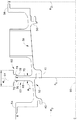
図2は、高圧タービン18の一部の概略図である。図3は、高圧タービン18の一部の拡大断面図である。タービン18は、複数の段30を含み、これら段の各々は、タービンブレード32の列とステータベーン34の列とを含む。タービンブレード32は、ロータシャフト26に結合されたロータディスク(図示せず)によって支持される。ステータケーシング36は、タービンブレード32及びステータベーン34の周りで円周方向に延びて、ベーン34がケーシング36によって支持されるようになる。
FIG. 2 is a schematic view of a portion of the
ケーシング36は、ベースケースセグメント38を含む。ケースセグメント38は、前部取付けフック40と中間取付けフック41とを含む。取付けフック40及び41は、ケースセグメント38内にシュラウドチャネル52を画成する。シュラウドチャネル52内の前部シュラウド組立体42は、取付けフック40及び41に結合される。ケースセグメント38はまた、後部取付けフック50を含み、この後部取付けフック50は隣接する下流側シュラウド組立体43に結合される。各シュラウド組立体42及び43は、各々がタービンブレード先端46の半径方向外側に位置するシュラウド44及び45を含み、該シュラウド44及び45とタービンブレード先端46との間に先端クリアランス48が画成されるようになる。
The
ケースセグメント38はさらに、エンジン10内で該ケースセグメント38をほぼ半径方向に結合するための前部取付けフランジ54及び後部取付けフランジ56を含む。前部取付けフック40が、前部取付けフランジ54から半径方向内向きに延び、また後部取付けフック50が、後部取付けフランジから半径方向内向きに延びる。取付けフック51は、ケースセグメント38の取付けフランジ56と隣接ケースセグメント59から延びる取付けフランジ58との間に結合される。従って、シュラウド組立体の取付けフック50及び51は両方とも、ケースセグメント取付けフランジ、具体的には取付けフランジ56及び取付けフランジ58において配置される。
The
擬似フランジ組立体60が、半径方向に中間取付けフック41と対向してケースセグメント38から延びる。擬似フランジ60は、リム62と該リム62の外径に結合されたリング64とを含む。より具体的には、リム62は、エンジン中心線66に対して測定した半径R1を有し、この半径R1は、ケースセグメント前部取付けフランジ54の半径R2及び後部取付けフランジ56の半径R3の1つよりも僅かに大きい。リム62は、シュラウド組立体42の中間取付けフック42と半径方向に対向してベースケーシング38内に形成される。1つの実施形態では、リム62は、機械加工法によって形成される。例示的な実施形態では、リム62は、直立した平行側面を有しており機械加工するのを可能にする。しかしながら、別の実施形態では、リムの側面68、70は、非平行となっている。
A
リング64は、リム62の幅W2よりも大きい幅W1を有し、その中に溝72が形成される。溝72は、リム62の外周部の少なくとも一部を受けるような寸法にされる。リング64はさらに、溝72の各側面76、78を囲むリップ74を含み、リング64とリム62との間の軸方向移動を阻止するのを可能にする。1つの実施形態では、リング64は、焼嵌め係合によってリム62に結合される。リング64は、個別に機械加工され、あらゆる幾何学的形状に製作することができる。リング64はまた、該リング64及びリム62の組み合わせた熱特性をケースセグメント取付けフランジ54及び56の熱特性に整合(一致)させることができるように該リング64が寸歩決めされる限り、ケース材料とは異なる材料で製作することもできる。
擬似フランジ60は、シュラウド組立体42の中間取付けフック41の位置においてリング62をベースケースセグメント38内に機械加工することによって形成される。機械加工を容易にするために、リム62は、ほぼ直立した平行側面を持つように機械加工される。リム62は、前部取付けフランジ54の半径R2及び後部取付けフランジ56の半径R3の1つよりも僅かに大きい半径R1を有するように機械加工されて、リム62は、前部取付けフランジ54の直径(図示せず)及び後部取付けフランジ56の直径(図示せず)の1つよりも同様に僅かに大きい直径(図示せず)を有するようになる。リング64は、リム62の外周部を受けるような寸法にされた溝72を有するように機械加工される。リング64は、該リング64のリム62に対するあらゆる軸方向移動を阻止するためのリップ74を溝72の両側に備えている。製作後に、リング64を加熱して、リング64が十分に膨張して前部取付けフランジ54及び後部取付けフランジ56の1つを通過するようにし、その結果、リム62上にリング64を嵌合することができるようになる。リング64が冷却すると焼嵌めが形成される。
The
作動中、タービン性能は、先端クリアランス48によって左右されので、ブレード先端46がシュラウド44及び45に接触しないようにしながら先端クリアランス48を設計最小間隔に維持するのが望ましい。先端クリアランス48を最適化しかつ維持するために、ケースセグメント38も含めてタービンケーシング36の熱膨張をロータディスク(図示せず)及びタービンブレード32の熱膨張にほぼ整合させるのが望ましい。ベースケースセグメント38上に擬似フランジ組立体60を設けて、シュラウド組立体42用の取付けフック40及び41におけるケースセグメント38の熱膨張特性を、それぞれ前部及び後部ケース取付けフランジ54及び56の熱膨張特性に整合させることができるようにし、その結果、シュラウドに対するタービンブレード先端のクリアランス48を維持するのが可能になる。
During operation, turbine performance is affected by
1つの実施形態では、熱膨張を整合させることは、フランジ54及び56を含むケーシングフランジ並びに擬似フランジ組立体60を可変量の冷却空気で冷却することによって可能となる。1つの実施形態では、冷却空気は、圧縮機吐出空気である。擬似フランジ組立体60の温度特性をケーシングフランジ54および56と整合させることにより、シュラウド組立体42のあらゆる振動を回避することが可能になり、これによって、シュラウド組立体42とタービンブレード32との間の接触を防止することが可能になる。
In one embodiment, matching thermal expansion is possible by cooling the casing
上述した擬似フランジは、ケースセグメントにおける熱膨張特性を整合させてシュラウドに対するタービン先端のクリアランスを維持することができるようにするために利用できる費用効果のあるフランジを提供する。擬似フランジは、該擬似フランジの領域内のブリードポートの設計も簡単にすることができる簡易型設計のものである。さらに、擬似フランジでは、ケーシングの材料とは異なる材料製のリングを使用することができ、このことにより、リング材料とケース材料との間の異なる熱膨張率のために良好な熱的整合を得ることできる。 The pseudo flange described above provides a cost effective flange that can be utilized to match the thermal expansion characteristics in the case segment to maintain the clearance of the turbine tip to the shroud. The pseudo flange is of a simplified design that can simplify the design of the bleed port in the area of the pseudo flange. In addition, the pseudo-flange can use a ring made of a material different from the casing material, which gives a good thermal alignment due to the different coefficient of thermal expansion between the ring material and the case material. I can.
以上、タービンケーシングシュラウドの例示的な実施形態を詳細に説明している。各シュラウドケーシング組立体は、本明細書に記載した特定の実施形態に限定されるものではなく、むしろ各構成要素は本明細書に記載した他の構成要素から独立してかつ別個に利用することができる。各構成要素はさらに、他のタービンケーシングシュラウド組立体と組み合わせて使用することもできる。 The exemplary embodiments of the turbine casing shroud have been described in detail above. Each shroud casing assembly is not limited to the specific embodiments described herein, but rather each component is utilized independently and separately from the other components described herein. Can do. Each component can also be used in combination with other turbine casing shroud assemblies.
なお、特許請求の範囲に記載された符号は、理解容易のためであってなんら発明の技術的範囲を実施例に限縮するものではない。 In addition, the code | symbol described in the claim is for easy understanding, and does not limit the technical scope of an invention to an Example at all.
18 タービン
32 タービンブレード
34 ステータベーン
36 エンジンケーシング組立体
38 ベースケーシング
40 前部取付けフック
41 中間取付けフック
42、43 シュラウド組立体
44、45 シュラウド
46 タービンブレード先端
48 先端クリアランス
50 後部取付けフック
52 シュラウドチャネル
54 前部取付けフランジ
56 後部取付けフランジ
60 擬似フランジ組立体
62 リム
64 環状のリング部材
72 溝
74 リップ
18
Claims (7)
前部フランジ(54)と、後部フランジ(56)と、前記前部フランジ及び後部フランジ間で延び、その中に少なくとも1つのチャネル(52)が画成された本体とを含むベースケーシング(38)と、
前記ベースケーシング(38)に結合され、前記前部及び後部フランジ(54、56)の熱膨張率と実質的に同一の率で熱膨張するように構成された環状のリング部材(64)と、
を含む組立体。 An engine casing assembly (36) for a gas turbine engine comprising:
A base casing (38) comprising a front flange (54), a rear flange (56), and a body extending between the front and rear flanges and having at least one channel (52) defined therein. When,
An annular ring member (64) coupled to the base casing (38) and configured to thermally expand at a rate substantially the same as that of the front and rear flanges (54, 56);
An assembly comprising:
Applications Claiming Priority (1)
| Application Number | Priority Date | Filing Date | Title |
|---|---|---|---|
| US10/642,719 US6848885B1 (en) | 2003-08-18 | 2003-08-18 | Methods and apparatus for fabricating gas turbine engines |
Publications (2)
| Publication Number | Publication Date |
|---|---|
| JP2005061418A true JP2005061418A (en) | 2005-03-10 |
| JP2005061418A5 JP2005061418A5 (en) | 2007-09-27 |
Family
ID=34063447
Family Applications (1)
| Application Number | Title | Priority Date | Filing Date |
|---|---|---|---|
| JP2004236971A Withdrawn JP2005061418A (en) | 2003-08-18 | 2004-08-17 | Method and device for fabricating gas turbine engine |
Country Status (3)
| Country | Link |
|---|---|
| US (1) | US6848885B1 (en) |
| EP (1) | EP1508673A3 (en) |
| JP (1) | JP2005061418A (en) |
Cited By (1)
| Publication number | Priority date | Publication date | Assignee | Title |
|---|---|---|---|---|
| JP2007538199A (en) * | 2004-05-17 | 2007-12-27 | カルダレア、エル、ジェームス、ジュニア | Turbine case reinforcement in gas turbine jet engines. |
Families Citing this family (11)
| Publication number | Priority date | Publication date | Assignee | Title |
|---|---|---|---|---|
| US8191254B2 (en) | 2004-09-23 | 2012-06-05 | Carlton Forge Works | Method and apparatus for improving fan case containment and heat resistance in a gas turbine jet engine |
| US7377742B2 (en) * | 2005-10-14 | 2008-05-27 | General Electric Company | Turbine shroud assembly and method for assembling a gas turbine engine |
| US8079773B2 (en) * | 2005-10-18 | 2011-12-20 | General Electric Company | Methods and apparatus for assembling composite structures |
| US8393855B2 (en) * | 2007-06-29 | 2013-03-12 | General Electric Company | Flange with axially curved impingement surface for gas turbine engine clearance control |
| US8197186B2 (en) * | 2007-06-29 | 2012-06-12 | General Electric Company | Flange with axially extending holes for gas turbine engine clearance control |
| GB0909470D0 (en) * | 2009-06-03 | 2009-07-15 | Rolls Royce Plc | A guide vane assembly |
| WO2014051686A1 (en) * | 2012-09-26 | 2014-04-03 | United Technologies Corporation | Combined high pressure turbine case and turbine intermediate case |
| WO2015021222A1 (en) | 2013-08-07 | 2015-02-12 | United Technologies Corporation | Clearance control assembly |
| US9598981B2 (en) * | 2013-11-22 | 2017-03-21 | Siemens Energy, Inc. | Industrial gas turbine exhaust system diffuser inlet lip |
| US9784132B2 (en) * | 2015-04-20 | 2017-10-10 | Pratt & Whitney Canada Corp. | Voltage discharge channelling assembly for a gas turbine engine |
| EP3153671A1 (en) * | 2015-10-08 | 2017-04-12 | MTU Aero Engines GmbH | Protection device for a turbomachine |
Family Cites Families (8)
| Publication number | Priority date | Publication date | Assignee | Title |
|---|---|---|---|---|
| FR996476A (en) * | 1949-10-01 | 1951-12-19 | Cem Comp Electro Mec | Cylinder for gas turbines |
| US2749026A (en) * | 1951-02-27 | 1956-06-05 | United Aircraft Corp | Stator construction for compressors |
| GB2019954B (en) * | 1978-04-04 | 1982-08-04 | Rolls Royce | Turbomachine housing |
| US4840026A (en) * | 1988-02-24 | 1989-06-20 | The United States Of America As Represented By The Secretary Of The Air Force | Band clamp apparatus |
| US5154575A (en) * | 1991-07-01 | 1992-10-13 | United Technologies Corporation | Thermal blade tip clearance control for gas turbine engines |
| GB9709086D0 (en) * | 1997-05-07 | 1997-06-25 | Rolls Royce Plc | Gas turbine engine cooling apparatus |
| US6290455B1 (en) * | 1999-12-03 | 2001-09-18 | General Electric Company | Contoured hardwall containment |
| US6514041B1 (en) * | 2001-09-12 | 2003-02-04 | Alstom (Switzerland) Ltd | Carrier for guide vane and heat shield segment |
-
2003
- 2003-08-18 US US10/642,719 patent/US6848885B1/en not_active Expired - Fee Related
-
2004
- 2004-08-13 EP EP04254882A patent/EP1508673A3/en not_active Withdrawn
- 2004-08-17 JP JP2004236971A patent/JP2005061418A/en not_active Withdrawn
Cited By (2)
| Publication number | Priority date | Publication date | Assignee | Title |
|---|---|---|---|---|
| JP2007538199A (en) * | 2004-05-17 | 2007-12-27 | カルダレア、エル、ジェームス、ジュニア | Turbine case reinforcement in gas turbine jet engines. |
| JP4802192B2 (en) * | 2004-05-17 | 2011-10-26 | カルダレア、エル、ジェームス、ジュニア | Turbine case reinforcement in gas turbine jet engines. |
Also Published As
| Publication number | Publication date |
|---|---|
| EP1508673A3 (en) | 2007-06-13 |
| US20050042090A1 (en) | 2005-02-24 |
| EP1508673A2 (en) | 2005-02-23 |
| US6848885B1 (en) | 2005-02-01 |
Similar Documents
| Publication | Publication Date | Title |
|---|---|---|
| EP1630385B1 (en) | Method and apparatus for maintaining rotor assembly tip clearances | |
| US7217089B2 (en) | Gas turbine engine shroud sealing arrangement | |
| EP2075437B1 (en) | Multi-source gas turbine cooling | |
| US7798775B2 (en) | Cantilevered nozzle with crowned flange to improve outer band low cycle fatigue | |
| JP5156362B2 (en) | Coronal rail for supporting arcuate elements | |
| JP5723101B2 (en) | Gas turbine engine temperature management method and apparatus | |
| EP2998520B1 (en) | Inter stage seal for gas turbine engine | |
| US20110236200A1 (en) | Gas turbine engine with non-axisymmetric surface contoured vane platform | |
| JP2004060656A (en) | Internal cooling of low pressure turbine case | |
| JP2004332737A (en) | Method and device for controlling rotor blade tip clearance in gas turbine engine | |
| CA2845457A1 (en) | Turbine shroud segment sealing | |
| WO2013074165A2 (en) | Asymmetric radial spline seal for a gas turbine engine | |
| EP3453842B1 (en) | Active clearance control manifold assembly and corresponding gas turbine engine | |
| JP2008133829A (en) | Device for facilitating reduction of loss in turbine engine | |
| US20190218925A1 (en) | Turbine engine shroud | |
| JP6329657B2 (en) | Sealed cooling of turbine shroud | |
| JP2017110652A (en) | Active high pressure compressor clearance control | |
| JP2005061418A (en) | Method and device for fabricating gas turbine engine | |
| US11377957B2 (en) | Gas turbine engine with a diffuser cavity cooled compressor | |
| EP2971665B1 (en) | Splitter for air bleed manifold | |
| US11377963B2 (en) | Component for a turbine engine with a conduit | |
| US20230035302A1 (en) | Clearance control assembly |
Legal Events
| Date | Code | Title | Description |
|---|---|---|---|
| A521 | Request for written amendment filed |
Free format text: JAPANESE INTERMEDIATE CODE: A523 Effective date: 20070814 |
|
| A621 | Written request for application examination |
Free format text: JAPANESE INTERMEDIATE CODE: A621 Effective date: 20070814 |
|
| A761 | Written withdrawal of application |
Free format text: JAPANESE INTERMEDIATE CODE: A761 Effective date: 20080428 |