JP2004533508A - Barrier-coated plastic container - Google Patents
Barrier-coated plastic container Download PDFInfo
- Publication number
- JP2004533508A JP2004533508A JP2002585526A JP2002585526A JP2004533508A JP 2004533508 A JP2004533508 A JP 2004533508A JP 2002585526 A JP2002585526 A JP 2002585526A JP 2002585526 A JP2002585526 A JP 2002585526A JP 2004533508 A JP2004533508 A JP 2004533508A
- Authority
- JP
- Japan
- Prior art keywords
- coating
- vacuum chamber
- plastic container
- thin
- inorganic
- Prior art date
- Legal status (The legal status is an assumption and is not a legal conclusion. Google has not performed a legal analysis and makes no representation as to the accuracy of the status listed.)
- Withdrawn
Links
Images


Classifications
-
- B—PERFORMING OPERATIONS; TRANSPORTING
- B05—SPRAYING OR ATOMISING IN GENERAL; APPLYING FLUENT MATERIALS TO SURFACES, IN GENERAL
- B05D—PROCESSES FOR APPLYING FLUENT MATERIALS TO SURFACES, IN GENERAL
- B05D1/00—Processes for applying liquids or other fluent materials
- B05D1/62—Plasma-deposition of organic layers
-
- C—CHEMISTRY; METALLURGY
- C23—COATING METALLIC MATERIAL; COATING MATERIAL WITH METALLIC MATERIAL; CHEMICAL SURFACE TREATMENT; DIFFUSION TREATMENT OF METALLIC MATERIAL; COATING BY VACUUM EVAPORATION, BY SPUTTERING, BY ION IMPLANTATION OR BY CHEMICAL VAPOUR DEPOSITION, IN GENERAL; INHIBITING CORROSION OF METALLIC MATERIAL OR INCRUSTATION IN GENERAL
- C23C—COATING METALLIC MATERIAL; COATING MATERIAL WITH METALLIC MATERIAL; SURFACE TREATMENT OF METALLIC MATERIAL BY DIFFUSION INTO THE SURFACE, BY CHEMICAL CONVERSION OR SUBSTITUTION; COATING BY VACUUM EVAPORATION, BY SPUTTERING, BY ION IMPLANTATION OR BY CHEMICAL VAPOUR DEPOSITION, IN GENERAL
- C23C14/00—Coating by vacuum evaporation, by sputtering or by ion implantation of the coating forming material
- C23C14/22—Coating by vacuum evaporation, by sputtering or by ion implantation of the coating forming material characterised by the process of coating
- C23C14/24—Vacuum evaporation
- C23C14/32—Vacuum evaporation by explosion; by evaporation and subsequent ionisation of the vapours, e.g. ion-plating
Landscapes
- Chemical & Material Sciences (AREA)
- Engineering & Computer Science (AREA)
- Mechanical Engineering (AREA)
- Plasma & Fusion (AREA)
- Chemical Kinetics & Catalysis (AREA)
- Materials Engineering (AREA)
- Physics & Mathematics (AREA)
- Metallurgy (AREA)
- Organic Chemistry (AREA)
- Details Of Rigid Or Semi-Rigid Containers (AREA)
- Chemical Vapour Deposition (AREA)
- Laminated Bodies (AREA)
- Physical Vapour Deposition (AREA)
- Coating Of Shaped Articles Made Of Macromolecular Substances (AREA)
Abstract
バリヤー被膜を有するプラスチック製容器(102)、例えば飲料包装用容器を製造する方法およびシステムを提供する。このシステムは真空槽、前記真空槽の中に位置していて被覆用蒸気を前記真空槽の中に位置させたプラスチック製容器(102)の外側表面に供給する被覆源(106)、および1種以上のプロセスガスを前記真空槽の内部空間部の中に供給するガス供給源(115)を含んで成る。前記被覆源を用いて無機被覆用材料(108)、例えば金属またはケイ素などを加熱して蒸発させることで被覆用蒸気を生じさせ、これにエネルギーを与えることでプラズマを発生させる。前記プロセスガスには炭素含有ガス、例えばアセチレンなどが含まれる。前記被覆用蒸気および/またはプラズマが前記プロセスガスの中の少なくとも1種と反応して前記プラスチック製容器の外側表面に薄い被膜が付着して接着するが、前記薄い被膜は炭素と無機材料、例えば無機酸化物などを含んで成る。A method and system for manufacturing a plastic container (102) having a barrier coating, such as a beverage packaging container. The system includes a vacuum chamber, a coating source (106) for supplying coating vapor to an outer surface of a plastic container (102) located within the vacuum chamber and positioned within the vacuum chamber, and one type. A gas supply source (115) for supplying the above process gas into the internal space of the vacuum chamber is provided. The coating source is heated to evaporate the inorganic coating material (108), for example, metal or silicon, to generate a coating vapor, and to apply energy to generate a plasma to generate a plasma. The process gas includes a carbon-containing gas, such as acetylene. The coating vapor and / or plasma react with at least one of the process gases to deposit and adhere to a thin coating on the outer surface of the plastic container, wherein the thin coating is formed of carbon and an inorganic material, for example, It comprises an inorganic oxide or the like.
Description
【技術分野】
【0001】
本発明は、気体透過性を低下させるバリヤー被膜(barrier coating)を含有させたプラスチック製容器、例えば飲料用容器などに関し、前記バリヤー被膜は、取り扱いの誤用および容器壁の膨張によって引き起こされるバリヤー特性の損失に対して向上した耐性を示す。
【背景技術】
【0002】
プラスチック製容器は食料および飲料産業の成長する大きな分野を構成している。プラスチック製容器は伝統的な金属製およびガラス製容器に比べて数多くの利点を与える。それらは軽量であり、安価であり、非破壊性であり、透明であり、かつ製造および取り扱いが容易である。しかしながら、プラスチック製容器は特に要求がより厳しい食料用途では普遍的受け入れに限界があると言った大きな欠点を少なくとも1つ有する。そのような欠点は、水、酸素、二酸化炭素および他の気体および蒸気があらゆるプラスチック製容器を多少とも透過する点にある。いろいろな用途において、手頃な価格のプラスチックが示す透過率は、これに入れた食料および飲料の貯蔵寿命が大きく制限されるか或はプラスチック製容器を全く使用することができないほど高い。
【0003】
ガラス様もしくは金属様層をプラスチック製容器に付着させること、そしてプラスチック製容器を金属で被覆することで、プラスチック製容器の最も良好な特徴とより伝統的な容器が組み合わされた容器構造を得ることができることは公知である。例えば、金属で被覆されたポテトチップス用バッグをある時期商業的に入手することができた。しかしながら、パッケージの透明性が大きく重要である用途では、金属被覆被膜は受け入れられない。プラスチック製容器の外観を変えることなく前記容器の上に耐久性のあるガラス様被膜を得るのはよりずっと困難であることが認められている。
【0004】
ガラス様被膜をプラスチックフィルムの上に付着させた後に前記フィルムから軟質プラスチック製容器を成形する方法は数多く開発されてきた。しかしながら、前以て成形しておいた比較的硬質のプラスチック製容器、例えば炭酸飲料用として米国で通常用いられているポリエチレンテレフタレート(PET)製ボトルなどにガラス様被膜を付着させる目的で開発された方法は相対的に少なく、今までのところ、容器が受ける加圧の影響に耐えるに充分な耐久性を示し、前記加圧の後に気体および蒸気に対して向上したバリヤーを保持しかつ容器の再利用に悪影響を与えないガラス様被膜をプラスチック製容器の外側表面に付着させる方法は全く開発されていない。現在、加圧される飲料用容器は世界規模で非常に大きな市場を構成しているが、現在手頃な価格のプラスチックが示す透過率は極めて高く、プラスチック製容器を利用することができるいろいろな市場でそれの使用を制限している。
【0005】
そのように加圧される容器には、炭酸飲料用および非炭酸飲料用の両方のプラスチック製ボトルが含まれる。プラスチック製ボトルはいろいろな重合体で作られており、特に炭酸飲料用のプラスチック製ボトルは主にPETで作られている。しかしながら、そのような重合体は、全部、気体および蒸気に対していろいろな度合の透過性を示すことから、その中に入れる飲料の貯蔵寿命は限られていた。例えば、炭酸飲料用ボトルの寿命はCO2が失われることで制限される[貯蔵寿命は、典型的に、飲料の初期炭酸飽和度(carbonation)の17パーセントが失われるに要する時間として定義される]。その損失速度は、体積に対する表面の比率の影響から、ボトルの大きさを小さくすればするほど大きくなる。数多くの市場用途で小型容器が求められているが、そのようなケースでは、それによってプラスチック製ボトルの使用がひどく制限される。従って、向上した炭酸飽和保持特性(carbonation retention properties)を示す容器が得られたならば、これは望ましいことである。
【0006】
非炭酸飲料の場合にも酸素および/または水蒸気が拡散することが理由で同様な制限がかけられ、再び、ボトルの大きさが小さくなればなるほど重要性が増す。拡散はボトルまたは容器の中に入ることとそこから出て行くこと(拡散および侵入)の両方を意味する。周囲温度が高い条件下ではCO2の拡散そして酸素、水蒸気および他のガスの拡散に対する不透過性の度合(本明細書では「ガスバリヤー(gas barrier)」として記述する)が重要になる。高いガスバリヤーを示す外側被膜をプラスチック製ボトルに付着させておくとそれに詰められている飲料の品質が向上しかつ前記ボトルの貯蔵寿命が長くなる可能性があることから、それが小型ボトルの代替品になる可能性がより高くなり、それによって、配達費用が軽減されかつマーケティングミックス(marketing mix)がより柔軟になる点で数多くの利点が得られる。
【0007】
また、プラスチック製容器、例えばPET製ボトルなどを再利用することができれば、これも望ましいことである。しかしながら、公知のバリヤー向上被膜(barrier enhanced coatings)はしばしば有機で相対的に厚く、従って再利用されたプラスチック製品を汚染する可能性がある。有機被覆用材料が再利用されたプラスチックの中に混ざると、飲料もしくは食料品がそのような有機被覆用材料と接触して汚染される可能性があることから、それは飲料もしくは食料品用容器として用いるに適さない。加うるに、被膜の厚みが相対的に厚いとプラスチック材料を再生利用している時にそれが相対的に大きな粒子を形成することから、結果として得られる再利用プラスチック製品の外観および特性が損傷を受ける可能性がある。特に、相対的に大きな被覆粒子(coating particles)が再利用プラスチックの中に入り込むと、それが入っていない時には透明なプラスチックが曇ってしまう可能性がある。曇っているプラスチックは飲料および食料品用容器などの如き容器ではしばしば望ましくない。
【0008】
加うるに、被膜をボトルの外側に付着させる時の費用が基礎パッケージ(basic package)のコストに大きく加わってはならない。このことは、被膜がボトルに入っている飲料の貯蔵寿命を大きく長くし、ボトルに入っている飲料の製品腐敗を大きく低下させ、紫外線による製品腐敗を大きく低下させ、環境応力亀裂(environmental stress cracking)を実質的になくしそして/または特定の色を与えるガスバリヤーであっても当てはまる。このような判断基準によって、高いガスバリヤーを示す被膜を生じさせようとする数多くの方法が除外されている、と言うのは、プラスチック製ボトルはこれ自身が非常に低コストで大量生産される製品であるからである。手頃な価格(affordability)は、実際、被膜の費用がパッケージ全体の価格に加わる度合が最小限であるか或はそれによって価格が高くなるべきでなく、実際に費用がより低い可能性があることを意味する。
【0009】
プラスチック製ボトルの外側に付着させる被膜は柔軟性を示すべきである。ボトルが加圧される容器として用いられる場合、その被膜は、プラスチック基質が伸びる時にはいつでも好適には二軸方向に伸び得るべきである。また、その被膜は容器表面の大部分に渡って連続的であるのが好ましい。特に炭酸飲料の場合には接着力が重要である、と言うのは、ボトルに入っているCO2がボトル内の圧力のいくらかまたは全部をその被膜に及ぼすからである。そのような圧力は6バールを超える圧力にまで上昇する可能性があり、それによって、被膜/プラスチック接触面にかなりの力がかかる。また、その被膜はかき傷、通常の取り扱い、気候(例えば雨、太陽および温度変動にさらされる)にも耐える必要がありかつその被膜はこれのガスバリヤーをボトルの有効寿命全体に渡って維持しなければならない。
【0010】
ある範囲の製品(これにはある場合にはボトルが含まれる)に外側の無機被膜を付着させるプラズマ増強方法(plasma−enhanced processes)がいくつか存在する。そのような方法の多くは、高いガスバリヤーを持たせるべきボトル用被膜とは全く異なるずっと厄介でない被膜特性を与えることを目的にしたものである。そのような方法は、例えば耐摩滅性を目的にしたものであり、その場合には被膜の連続性が重要な因子にはならない、と言うのは、そのような被膜を用いて非常に微細な隙間を保護することができるからである。他の方法は化粧品または光反射特性を目的にしたものでありそしていくつかの方法は単なる取り扱い保護の役割を持つものである。そのような基質はしばしば曲げられることも伸ばされることもなく、かつそのような製品はそれ自身がプラスチック製ボトルの価格よりも高く、その結果として、価格がデザインの利点にはならない。ある場合には、そのような基質を用いた時に許される被覆温度は、最も一般的なプラスチック製ボトル材料であるPETを用いた時に許される温度よりもずっと高い。そのような方法を用いたのでは一般に高いガスバリヤーを示す被膜を与えるに必要な被膜の連続性、接着力および柔軟性を与えるのは不可能であり、かつこの上に記述した高いガスバリヤーを示す被膜に関連した他の問題に対する解決法を与えるものでもない。
【0011】
無機被膜をプラスチック基質に真空下で付着させた時の付着力をプラズマで増強させる電気アーク方法が特許文献1に記述されており、それは前記欠点および問題を取り扱うものである。冷却した陰極と陽極の間に低電圧の電気アークを発生させており、その陽極は被覆用固体(coating solids)[これはアークのエネルギーで蒸発しかつプラズマエネルギーが与えられる(plasma−energized)]を保持しているるつぼである。そのプラズマに1種以上の反応性ガスを加えてもよい。そのプラズマに入っている高エネルギーの粒子の比率が相対的に高いことが理由で良好に接着する濃密な被膜付着が得られる。そのような方法を用いると外側のガラス様バリヤー被膜(barrier coatings)を有するプラスチック製容器が得られる。
【0012】
しかしながら、ある用途のプラスチック製容器は非常に高い度合の取り扱いの誤用(handling abuse)および/またはプラスチック基質の大きな膨張をもたらす条件に耐える必要がある。高い度合の取り扱いの誤用はボトル詰めプラント、配達中および市場で起こり得る。そのような誤用の例には、(i)空ボトルの貯蔵室およびそのような貯蔵後のボトル仕分け/組立て(sorting/erection)装置の使用(これによってボトルが互いおよび金属製接触部分に対して連続的に擦られ、それによってしばしばそれらがひどく引っ掻かれると言った影響が生じる)、(ii)ボトルに熱水を噴霧するボトルウォーマー(bottle warmers)の使用[それによって表面が熱く湿った条件にさらされかつ水にいくらか入っている添加剤、例えばさび落とし剤(de−scaling agents)などによる化学的影響を受ける]、(iii)ガラス製容器を取り扱うように設計されたボトル詰めライン(PET製容器を専用に取り扱うように設計されていない)の使用(このようなラインは一般にプラスチック製容器の取り扱いにとってあまり優しくない)、そして(iv)容器が熱くて埃っぽい条件の中で長距離に渡って配達されること(その結果として、容器と容器の接触および摩滅が理由で過度の損傷がもたらされる)が含まれる。容器の大きな膨張をもたらす条件は一般に高い周囲温度と湿度の組み合わせであり、これは特に炭酸飽和状態が高い飲料の時に起こり(そのような飲料を取り扱う容器の内部圧力が高いことにより)、かつまた特に装飾的特徴を有する輪郭を持たせたパッケージの場合に起こる(そのような特徴によって容器の壁が弱くなることにより)。この上の例で示した如き取り扱いの誤用および/または容器の大きな膨張をもたらす条件によって被膜が過度の損傷を受ける可能性があり、その結果として、バリヤーが大きく失われてしまうであろう。そのような誤用および条件では、ある市場のポイントオブセール(point−of−sale)でバリヤーが大きく損失しないように、特許文献1に記述されている被膜デザイン尺度(coating design measures)を超える被膜デザイン尺度が要求され得る。ある用途ではより強い被膜の方が有利であろう。
【特許文献1】
PCT WO 98/40531
【発明の開示】
【発明が解決しようとする課題】
【0013】
従って、本発明の目的は、摩滅および他の取り扱いの誤用かつプラスチック基質の大きな膨張をもたらす条件が理由で起こるバリヤー損失の度合を低くするバリヤー被膜を有する(barrier coated)プラスチック製容器およびこれの被覆方法を提供することある。
【0014】
本発明の別の目的は、摩滅および他の取り扱いの誤用に対する耐性かつプラスチック基質の大きな膨張をもたらす条件に対する耐性が向上した外側被膜を容器、例えば熱に敏感なプラスチック製ボトルなどに与えることにある。
【0015】
本発明のさらなる目的は、特許文献1に記述されている方法を用いた時にもたらされるバリヤーに比較して向上したバリヤーを示す被膜をプラスチック製容器に与えることにある。
【0016】
本発明の更に別の目的は、容器の曲げ、引き伸ばし、へこみおよび摩滅の影響に高いバリヤー特性の大きな喪失なしに耐える柔軟で耐久性があって充分な接着力を有する外側のガラス様被膜を与え得る被膜およびシステム(system)および被覆方法を提供することにある。
【課題を解決するための手段】
【0017】
ガスバリヤーを示しかつ取り扱いの誤用および容器の壁の膨張が原因で起こるバリヤーの喪失に対して向上した耐性を示す被膜を有するプラスチック製容器を製造するシステムを提供する。このシステムは(a)真空槽(vaccume cell)[この真空槽の中に真空を維持することができる]、(b)前記真空槽の中に位置していてこの真空槽の中に位置させたプラスチック製容器の外側表面に被覆用蒸気を供給する少なくとも1種の被覆源(coating source)[この被覆源は、無機被覆用材料、例えば金属またはケイ素などを加熱しかつ蒸発させて被覆用蒸気(coating vapor)を生じさせる蒸発装置、および前記被覆用蒸気にエネルギーを与えてプラズマを発生させる手段を含んで成る]、および(c)1種以上のプロセスガス(process gases)を前記真空槽の内部空間部の中、通常はプラズマ発生領域の中に供給するガス供給源(gas feeds)を含んで成る。前記プロセスガスの中の少なくとも1種は炭素含有ガス、好適には低分子量の有機ガス、例えばアセチレン、エチレンまたはエタンなどである。前記被覆源を前記真空槽の中に前記プラズマが前記プロセスガスの中の少なくとも1種と反応して薄い被膜が前記プラスチック製容器の外側表面に付着して接着し、結果として前記薄い被膜が炭素と無機材料[この無機材料は例えば澄んだ/透明な(clear/transparent)無機酸化物である]を含んで成るように位置させる。そのような被覆用成分の組み合わせを用いると良好なガスバリヤーが得られることに加えてバリヤーの喪失に対する耐性が向上する。
【0018】
無機材料および炭素含有ガスの選択に応じて多様なバリヤー被膜を生じさせることができ、そのような被膜には、無色透明な酸化物被膜、不透明または半透明の被膜および着色した被膜が含まれる。
【0019】
本システムに、更に、多数のプラスチック製容器を前記真空槽の中に移送してそれらが被覆工程を好適には連続様式または半連続様式で通るように移送する容器供給装置およびコンベヤーを含めてもよい。
【0020】
別の態様における本システムは、この上に記述した如き真空槽および少なくとも1種の主被覆源に加えて、(a)1種以上のプロセスガスを前記真空槽の内部空間部の中に供給するガス供給源および(b)同じまたは別の真空槽の中に位置していて重合体の1つ以上の被膜を前記真空槽の中に位置させたプラスチック製容器に付加させる少なくとも1種の重合体被覆源(polymer coating source)を含んで成る。前記主被覆源を前記真空槽の中に前記プラズマが前記プロセスガスの中の少なくとも1種(場合により炭素含有ガスを含有)と反応して薄い被膜が前記プラスチック製容器の外側表面に付着して接着し、結果として前記薄い被膜が無機材料、例えば無機酸化物などを含んで成るように位置させる。1番目の種類の本システムにおける重合体被覆源は、重合性ガスを含んで成る2番目のガス供給源と、前記重合性ガスにエネルギーを与えて重合性フリーラジカルを含んで成るプラズマを発生させる手段を含んで成り、その結果として、その重合性フリーラジカルが前記プラスチック製容器に付着して重合することで薄い重合体被膜を形成する。そのような重合性ガスの例にはオレフィン、パラフィンおよびこれらの混合物が含まれる。エチレンおよびアセチレンが好適である。2番目の種類の本システムにおける重合体被覆源は、蒸発性(vaporizable)重合体を加熱して蒸発させて重合体被覆用蒸気を発生させる溶融−蒸発装置(melter−evaporator)を含んで成り、前記重合体被覆用蒸気は前記プラスチック製容器の上で再凝縮してそれに付着することで薄い重合体被膜を形成する。前記蒸発性重合体は、真空条件下で分解を起こすことなく蒸発し得る重合体、例えばポリオレフィン、ポリエステル、ポリカーボネートなど、またはこれらの混合物である。ポリエチレンが好適な重合体である。いずれの種類の本システムでも、そのような薄い重合体被膜を主無機被膜に関してトップコート(topcoat)、アンダーコート(undercoat)または両方として付着させてもよい。任意の炭素成分の有り無しで無機被膜と重合体プレ−および/またはポスト−コート(pre− and/or post−coat)を組み合わせると、良好なガスバリヤーが得られることに加えてバリヤーの喪失に対して向上した耐性が得られる。
【0021】
好適な態様の前記被膜を持たせたプラスチック製容器は、内部容積の中に4倍体積の二酸化炭素を入れて密封した時、取り扱いの誤用および環境の苛酷な条件を受けた後でも、前記被膜を持たせていない前記プラスチック製容器が示すガスバリヤーの少なくとも1.25xのガスバリヤーを示す。
【0022】
本システムを基にして被膜を有するプラスチック製容器を製造する方法を提供することに加えて前記被膜を有するプラスチック製容器自身も提供する。また、それに包装された飲料および包装システム(packaging systems)も提供する。
【発明を実施するための最良の形態】
【0023】
容器を被覆する方法およびシステムを開発し、その被膜は前記容器の表面に良好に接着しかつ良好なガスバリヤーを示すばかりでなく苛酷な取り扱いの誤用および前記容器の壁の膨張に耐えるに必要な耐摩滅性、引き伸ばし性および柔軟性を示す。
【0024】
前記被膜は取り扱いの誤用および容器壁の膨張が原因で起こるバリヤー喪失に対して向上した耐性を示すが、これは、主被膜を生じさせる時に用いる無機プロセスガスに炭素含有ガスを添加しそして/または重合性有機ガスを用いて薄い重合体アンダーコートを容器表面と主被膜の間に付着させそして/または重合性有機ガスを用いて薄い重合体トップコートを前記主被膜の上に付着させそして/または被覆工程の真空条件下で分解を起こすことなく蒸発して薄いアンダーコートもしくはトップコートの付着をもたらす重合体を用いることで達成したものである。
【0025】
本明細書の全体に渡って容器またはボトルを記述する。被覆されていない容器を容器本体と呼ぶこともあり得る。このような容器本体を一般にプラスチック製ボトルの言及で記述するが、本発明の方法およびシステムを用いて適切な如何なる容器に処理を受けさせてもよい。従って、いろいろな大きさのソフトドリンク用ボトル、他の食料品用容器または他の適切な如何なる容器にも本明細書に記述する方法およびシステムを用いた処理を受けさせることができる。
【0026】
用語「バリヤー」を本明細書で用いる場合、これは、特に明記しない限り、気体および蒸気の透過に対する抵抗を指す。
I. 炭素含有無機被覆方法およびシステム
特許文献1に記述されている無機バリヤー被膜に炭素を取り込ませる方法を開発した。その無機被膜の中に入り込んだ炭素がフリーラジカルを発生することで容器の表面が活性化され、それによって、その被膜の接着力がより良好になり得ることでそれのバリヤー特性が向上する。前記無機被膜の中に炭素を入り込ませると、また、(i)基質表面の欠陥部を覆う度合がより良好になり(と言うのは、気体は無機粒子よりもそのような欠陥部の中に入り込む度合が良好であり、それによって、被膜の中にピンホールが発生する率が低くなるか或は発生しなくなるからである)、(ii)被膜の柔軟性がより高くなり、従って、その被膜を亀裂なしに当該基質と同じ度合で曲げることができかつ膨張させることができ、それによって、苛酷な条件下で起こる容器の膨張が原因で起こるバリヤー損失の度合が低くなるか或はなくなり、(iii)無機格子の中に追加的架橋がもたらされることで被膜の一体性が向上し、そして(iv)被膜の脆さが低くなることで被膜が摩滅、取り扱いの誤用および容器膨張に対して示す耐性が向上することで、被膜のバリヤーが向上する。
【0027】
そのような炭素含有無機被膜は、高いバリヤーを与え得ることに加えてバリヤー喪失に対する耐性がより高いと言った利点をもたらす。1つの態様では、苛酷な取り扱いおよび環境条件下で大きく向上したバリヤーを示す澄んだ/透明な二酸化ケイ素被膜(「ガラス様」被膜)を生じさせることができる。例えば、そのような被膜はボトル詰めプラントで苛酷な取り扱いの誤用を受けた後でもボトルの大きな膨張をもたらす苛酷な環境条件にさらされた後でも向上したバリヤーを示し得る。
被覆システム
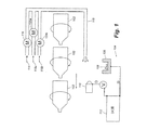
好適な態様における方法は特許文献1に記述されている方法を基にして組み立てた方法である。図1を参照して本方法の好適な態様を記述する。図1に示す容器102は真空槽の中で回転しながら1個または一連の被覆源104を連続的に通り過ぎる。前記被覆源104(また蒸発装置または蒸発装置システムとも呼ぶ)にはるつぼ106(これに無機被覆用物質108が入る)が含まれている。前記被覆源104には更に直流(「DC」)電源112のマイナス端子につながっている陰極110も含まれている。前記DC源112のプラス端子はるつぼ106につながっている。陰極110とるつぼ106の間で発生させた電気アークでるつぼ106を加熱する。前記電気アークのエネルギーによって無機被覆用物質108が溶融して蒸発しかつそれにエネルギーが与えられることでプラズマが発生する。また、そのような電気アークが有する溶融および蒸発機能の一部または全部を放射加熱装置または本技術分野で公知の他の形態の加熱で与えることも可能である。炭素含有ガス114(またはガス混合物)を流量調節装置116で計量し、導管115に通してるつぼ106の上に存在するプラズマの中に送り込む。また、118aおよび118bとして示す他のプロセスガスも流量調節装置120aおよび120bで計量し、そして導管115に通してか或は別法として他の個別の1つ以上の導管に通して、るつぼ106の上に発生させたプラズマの中に送り込む。ガス114、118aおよび118bをプラズマの中に導入すると、それにプラズマエネルギーが与えられ、そして炭素を含有する無機被膜が容器102の外側表面の上に生じる。
【0028】
本方法を真空下および真空槽、例えば特許文献1に記述されている如き真空槽の中で実施すべきである。炭素含有ガスを用いる時の本方法の操作圧力(operating pressure)は、被膜の種類に応じて10−4から10−1ミリバールの範囲、より通常には10−3から10−2ミリバールの範囲である。炭素含有ガスを用いる時の操作圧力は、被覆速度が等しい場合、無機被膜に炭素を含有させない場合に通常用いられる圧力よりも高い傾向がある。他の面における操作パラメーターは特許文献1および米国特許第6,279,505号に記述されているそれらの範囲内である。
【0029】
るつぼ106を典型的には冷却(例えば水で冷却)されているるつぼホルダー(示していない)で担持させる。このるつぼ(また入れ物とも呼ぶ)を、選択した特定の被覆用材料を溶融させて蒸発させるに適した材料で構成させ、これは、不活性である必要がありかつ要求される量の蒸気を発生させるに必要な温度に耐える必要がある。例えばケイ素を蒸発させる場合には炭素が適切な材料であることを確認した。
(1)炭素含有ガス
炭素含有ガス114には、好適には、低分子量の有機ガス、例えばアセチレン、軽質オレフィン(例えばエチレン、ブチレン、プロピレン)、または軽質パラフィン(例えばエタン、ブタン、プロパン)、または軽質芳香族(例えばベンゼン、トルエン)、または無機基を含有する軽質有機物(例えばニトリル、スルフィド、ホスフェート)が含まれる。一般的には、水素原子に対する炭素原子の比率が高い炭素含有ガス、例えば前記軽質オレフィンなどの使用が有利である。アセチレンが好適である。計量してプラズマに送り込む炭素含有ガスの量は、選択した無機被覆用物質の種類ばかりでなく炭素含有ガスの種類にも依存する。例えば、無機被覆用物質と一緒にアセチレンを過度の比率で用いるとそれは被膜に褐色がかった色を与えるであろう。例えば、アセチレンの蒸気圧をプラズマに入っている蒸気の無機内容物を一緒にした蒸気圧とほぼ等しくすると褐色がかった色合いがもたらされると予測される。
(2)無機被覆用物質およびプロセスガス
被覆用物質108は、室温で固体で高い沸点、例えば500℃を超える沸点を有する無機材料である。このような被覆用物質は例えば金属、ケイ素または他の非金属など、またはこれらの組み合わせであってもよい。
【0030】
いろいろな多原子価金属の金属酸化物、例えば酸化アルミニウムなどを炭素含有被膜に加えることで、取り扱いの誤用および環境条件に耐えるガラス様の澄んだ透明な良好なバリヤーを生じさせることができる。四価の金属、例えばチタンなどを炭素と組み合わせるのが特に有利である。
【0031】
そのような被覆用物質および工程の選択は、工程判断基準(費用、被膜の色、透明性、ボトルの形状、要求されるガスバリヤー度、ボトルの大きさ、特にボトルで用いられるプラスチックの種類)に依存する。炭素含有ガスを存在させない時には、本明細書に記述する手順を用い、ケイ素と酸素を表面で反応させてSiOx[ここで、xは一般に1.7より大きく、通常は2より僅かに小さい]を得、従ってガラスのように透明な被膜を生じさせることで良好なガスバリヤーを得た。炭素含有ガスを存在させる時には、ケイ素の原子価部位のいくらかが酸素ではなく炭素で占められることからxがより小さくなるが、同じ原理が当てはまり、その結果として、SiOyCz[ここで、y+zは1.7より大きく、通常は2より僅かに小さい]がもたらされる。
【0032】
また、そのような被膜にLi、Na、K、Rb、Cr、Mg、Ca、Sr、Ba、Ti、Al、Mn、V、Cr、Fe、Co、Ni、Zn、Cu、Sn、GeおよびInから成る群から選択されるガラス形成金属添加剤(glass−forming metal additives)の1種以上を0.01から50%含有させることも意図する。二酸化ケイ素および他の被膜に特定の金属を少量または痕跡量で添加するとガスバリヤーが向上し得る。そのような金属をガラス形成金属添加剤として記述することができる、と言うのは、それらはガラス製造で用いられる添加剤として知られているからである。適切なガラス形成金属添加剤にはAg、Al、Ca、Cr、Cu、Fe、K、Mg、Mn、Na、Ni、Sn、TiおよびZnが含まれる。このような金属を被膜中の金属の割合が0.01から50%になるように添加する。例えば、そのような添加剤をSiO2で主に構成されている被膜に添加するとガスバリヤーが2倍以上向上する。そのような金属をるつぼに添加するか或はそのような金属を電子発生プレート(electron emitting plate)または陰極のシールド(shield)(これを所望金属または金属混合物で構成させておく)の犠牲的侵食で与える。
【0033】
また、金属および他の気体状物質を用いて着色した被膜または紫外線吸収性被膜を生じさせることも可能である(反応体を適切に選択することで)。また、各層がいろいろな組成物を含んで成る2層以上も有益であり得、特に着色した被膜を生じさせようとする時には有益であり得る、と言うのは、着色した層と透明な層を組み合わせることで着色した被膜の厚みを最小限、従って再利用性を向上させた良好なガスバリヤーを得ることができるからである。無機被覆用材料を2種以上用いる場合、しばしば、被覆源を2種以上準備する必要がある、と言うのは、物質と物質の間の蒸気圧に差がある結果として被膜に存在する各物質の分別(fractionation)が起こりかつそれらの比率が制御不能になってしまう可能性があるからである。
【0034】
その上、本明細書に開示するシステムおよび方法を用いてプラスチック製容器本体を金属または他の無機材料、例えばケイ素(これは酸化物ではなくむしろ元素状金属である)または炭素を含有する他の無機材料などで被覆することも可能である。例えば、炭素含有ガス以外の、真空槽で用いる反応体ガスの使用量をなくすことで、プラスチック製容器本体を炭素含有元素状アルミニウムまたはケイ素で被覆することも可能である。その炭素含有ガスが反応を起こして元素状炭素が生じるが、無機材料は反応を起こさない。
【0035】
別の態様では、二酸化ケイ素被膜の代わりとして、炭素を含有する澄んだ/透明な金属酸化物被膜を高いバリヤーを伴わせて生じさせることができる。ガラスのような透明性が要求される高バリヤー用途で最初に選択するのは通常は二酸化ケイ素であるが、被覆源に連続的に供給するのはケイ素よりも金属の方がずっと容易である。その上、利用可能な無機被覆用材料の選択に多様な金属を加えると適切なるつぼ材料の選択が広がる。従って、炭素含有金属酸化物被膜を生じさせる時に金属を用いると二酸化ケイ素被膜に比較して被膜を生じさせる費用が大きく低下する可能性がある。
【0036】
るつぼに供給する無機材料源を自動化することができ、例えばロッド(rod)または他の固体状構造物または他の任意形態として自動化可能である。好適には、無機材料を固体形態でるつぼに供給し、特に厚切りのまたは非粉末形態で供給する。そのような材料の表面積を最小限にすることによって、有害な酸化の影響を回避することができる。
【0037】
1種以上のプロセスガス、例えば118aおよび118bの選択および使用は、用いる個々の無機被覆用物質および炭素含有ガスに依存する。例えば、無機被膜が酸化物の場合には酸素が必要なプロセスガスである。代替態様におけるプロセスガスには不活性ガス、例えばアルゴンなどが含まれ、これを用いてプラズマエネルギー供与工程(plasma−energization process)を向上させることができる。
被覆システムの操作
陰極をマイナス(陰)極の所に位置させそしてるつぼをプラス(陽)極の所に位置させて電位を陰極110とるつぼ106を両端にしてつなげることで、電子の流れの形態のエネルギーが陰極とるつぼの間を流れるようにすることができる。るつぼの水平面を基準にした陰極の位置を変えることでプラズマ発生および蒸発で利用できるエネルギーの割合を調整することができる。例えば、1番目の位置にするとプラズマ発生で利用できるエネルギーの分率が大きくなる一方、2番目の位置にするとエネルギーのほとんど全部が蒸発で用いられてプラズマはほとんど全く発生しない。無機被覆用材料108が蒸発した後に容器102の外側表面に付着して完全(即ち化学量論的)反応を起こし得る特定の付着速度がもたらされるように、プロセスガスを被覆用チャンバ(coating chamber)の中に導入しながら(従って、未反応ガスが被膜の中に有意な量で封じ込められないことを確保しながら)、被覆源104に与えられるエネルギーの度合を電圧で調整する。例えば、ケイ素を酸素および炭素含有プロセスガスと一緒に無機被覆用材料として用いる好適な1つの態様では、酸素(または空気)を過剰量にせずかつ被覆槽(coating cell)の中の真空度を高く(10−4ミリバールから10−2ミリバールの範囲に)維持しながら被覆表面への付着速度を1から50nm/秒にすると完全に透明な被膜を得ることができ、その結果として、SiOyCzにおけるy+zが実質的に2になる。
【0038】
良好なガスバリヤー結果がもたらされるようにしようとする場合には、被覆用材料が付着して固体状格子(solid lattice)が形成した後に表面上で被覆用材料とプロセスガスの間の反応が起こることを確保するのが有益である、と言うのは、プロセスガスがその後に反応を起こして固体状格子になることで被膜が濃密になるからである。同様に、炭素含有ガスに含まれる炭素が前記格子の中に入って一体化することで格子の柔軟性がより大きくなる。
【0039】
被覆用材料が容器表面に付着する前に被覆用材料がプロセスガスと反応することがないようにしようとする時には容器本体の表面とるつぼの間の距離が重要である。同様に、表面上で起こる反応が最大限になることを確保しようとする時には被覆用材料の状態が重要である。被覆源が最適に用いられる、従ってそれができる多くの容器を被覆し得るように距離を選択する。この距離は真空度および付着速度に依存するが、一般に0.50mから2mである。その距離を長くすることによって容器本体に熱による損傷を受けさせることなく被覆源の所に高エネルギーのプラズマを発生させることができる。
【0040】
真空槽の中で発生させるプラズマは高エネルギーのプラズマであり得るが、これは陰極の位置、電圧、陰極とるつぼの間の距離および被覆角(coating angle)(これは望ましくは0から70°の範囲である)で決まる。蒸発装置または被覆源を蒸発装置束がこれらの路(path)と重なり合うことで縦方向の付着速度Rが均一になるように列の状態で配置してもよい。前記速度は典型的に約1から50nm/秒の範囲であってもよい。好適な態様におけるプラスチック製容器は厚みが約0.35mmのPETで出来ているボトルであり、それに厚みが約50nmのバリヤー被膜を持たせる。
【0041】
プラスチック製容器が被覆源の上(かつ真空槽の中)を回転しながら移動するようにするが、これを、好適には、プラスチック製容器が最適に被覆されるように特許文献1に記述されている装置および方法を用いて実施する。容器本体を保持しそして/または被覆工程に通して移送する適切な手段を準備する。この工程はバッチ(batch)工程であってもよいか、或はより好適には連続または半連続工程である。
【0042】
あるプラスチック表面では、プラスチック製容器またはボトルの表面が軽く活性化されるように表面に予備活性化を受けさせてその表面にフリーラジカルを発生させるのが有効である。そのような予備活性化はプロセスガスを用いて実施可能であり、それを被覆工程が始まる前にプラズマの形態で適用する。通常は酸素または不活性ガスを予備活性化用ガスとして適用しそしてそれらにプラズマエネルギーを与える方法は図2に関連して本明細書の以下に記述する方法であり、その方法で用いる真空槽圧力条件は被覆で用いる条件と同じである。あるプラスチック基質では、吸収されている水分および低分子量材料を除去する目的で容器の表面に脱気を受けさせておくのが有効であり得る。このような脱気は当該容器を真空下に約5から180秒間保持することで達成可能である。ブロー成形直後のブロー成形ボトルまたは容器は脱気を相対的に迅速に受け得るが、ブロー成形機の所以外の被覆工程の場所の方が望ましい。
II. 本被膜を有するプラスチック製容器
本明細書に記述する方法を用いて、好適には、外側表面を有するプラスチック製容器本体を含んで成っていて前記容器の外側表面に被膜を有する被覆プラスチック製容器を生じさせる。その被膜は、当該容器の中に入る気体の流れおよび容器から出る気体の流れを抑制するバリヤーを与え、これは特に炭酸飲料の生産で用いるに有用である。例えば、そのようなガスバリヤー被膜は外から酸素が容器の中に流れ込まないようにすることで飲料を保護し得るか或は飲料用容器から二酸化炭素が流出しないようにし得る。その結果として、前記容器に付着させた被膜が二酸化炭素を前記容器内により良好に保持することから、炭酸飲料の貯蔵寿命がより長くなる。
【0043】
前記炭素/無機被膜はプラスチック製容器の表面に強力に接着し、その結果として、その被膜が不連続(例えばそれに引っ掻き傷または破損が生じることが原因で生じた)であっても前記被膜は基質、例えば下側に位置するプラスチック製ボトルなどに有効に接着し続けるであろう。従って、本明細書に記述する被膜は、表面が高度に破損を受けた時でも有効なガスバリヤーを与える。本明細書に記述する炭素含有無機被膜被覆方法を用いると、その被膜を持たせた容器に加圧された流体、例えば炭酸飲料などを入れた時でも、その被膜を持たせていない容器に比べて1.25x、好適には1.5x、より好適には2xの高いガスバリヤーを得ることができる。その上、本明細書に記述する被膜を有する容器は、表面積と容積は同様であるが前記外側無機被膜を持たないプラスチック製容器に比べて、軽量にして等しいガスバリヤーを示すように作成可能である。澄んだ/透明な被膜の好適な態様におけるバリヤー被膜は、無機酸化物と炭素と場合によりガラス形成金属添加剤の混合物を含んで成り、この被膜を持たせたプラスチック製容器は、この容器本体の内部空間部に60psig(4.1バール)の圧力に加圧された流体を入れて密封した時、この被膜を持たせていない容器の内部空間部に60psig(4.1バール)の圧力に加圧された流体を入れて密封した時にその被膜を持たせていない容器が示すガスバリヤーの少なくとも1.25xのガスバリヤーを示す。
【0044】
本被覆プラスチック製容器の炭素/無機被膜を好適には非常に薄くする。この被膜の厚みを好適には約1から約100nmにする。
【0045】
真空蒸着、好適にはプラズマ増強真空蒸着を用いて被膜を容器本体の外側表面に付着させることで本被覆プラスチック製容器の製造を行う。その結果として生じる被膜は好適には実質的に均一で非晶質であり、前記容器の外側表面に化学的、物理的またはこれらの組み合わせで接着している。用語「均一」を本明細書で用いる場合、これは、被膜を貫く原子組成に実質的なばらつきがないことを意味し、用語「非晶質」は、標準的x線回折技術で測定した時に被膜が実質的に結晶度を示さないことを意味する。加うるに、この被膜の成分は好適にはこの被膜の中に被膜の厚みを通して実質的に一定の濃度で存在する。例えば、澄んだ/透明な被膜の場合、この被膜の中に存在する無機酸化物、炭素およびガラス形成金属添加剤は被膜全体に渡って実質的に一定の濃度で存在すべきである。従って、その結果として生じた被膜は非常に高い耐久性を示す。
【0046】
作り出すことができるボトルの種類と被膜の組み合わせは多様である。本明細書に記述する方法およびシステムを用いて、また、熱に敏感な容器に被覆を大きな温度上昇なしにボトルの温度を常に60℃より充分低い温度に保持しながら受けさせることができる。加うるに、本方法およびシステムを用いて、付着させる物質の混合物および層を色、紫外線吸収特性または追加的ガスバリヤー特性に関して選択することができるようにすることも可能である。例となる態様では、シリカまたは金属酸化物被膜は充分に透明で澄んでおり、それを透明なボトルに付着させても、そのボトルの外観は影響を受けない。
【0047】
本明細書に記述する被覆方法を用いて、取り扱いの誤用に耐えて高バリヤーを示すことに加えて色または他の特徴を有するプラスチック製容器を製造することも可能である。前記炭素含有被膜は透明で澄んでいる(この場合には付着物を炭素と金属の酸化物もしくは非金属物質、例えばケイ素の酸化物のいずれかで構成させる)か或は不透明または着色していてもよい(この場合には付着物を炭素と金属または非金属、例えばケイ素などでか或は無機ガス、例えば窒素などの金属もしくは非金属化合物のいずれかで構成させる)。可視光を吸収する種を混合して追加的機能を無機被膜の中に組み込むことも可能であり、それによって、そのプラスチック製容器を化粧的により魅力のあるものにすることも可能である。例えば、炭素含有ケイ素被膜にちらちら光る褐色効果を持たせることで有害な紫外線の透過に対して良好な耐性を持たせることも可能である。別の例として、炭素含有金属被膜に鏡のような金属効果を持たせることも可能であり、これは例えば宣伝用包装で用いるに有用であり得る。
III. 重合体被覆方法およびシステム
本発明の別の面では、重合体被膜をプラスチック製容器に好適には前処理(アンダーコート)または後処理(オーバーコート)、より好適には前処理と後処理の両方(結果として主無機被膜が間に挟まれる)として付着させる方法を提供する。例えば、主被膜は本明細書に記述する炭素含有被膜または特許文献1に記述されている全体が無機の被膜のいずれかであってもよい。この方法は、重合性有機ガスをプラズマ増強システムに導入するか或は別法として分解を起こすことなく蒸発し得る重合体を真空槽の中で蒸発させることを包含する付着方法を伴う。
重合性有機ガス
図2を参照して本方法の好適な態様を記述する。図2において、容器202は回転しながら1個または一連のガス用エネルギー源(gas−energing source)204の所を連続的に通り抜ける。前記ガス用エネルギー源204にはガス供給用パイプ206(これの中をガス208が流れる)が含まれている。ガス208の流れおよび混合を流量調節装置210aおよび210b[または、ガス混合物に含める成分の数に応じて同様なさらなる装置(示していない)]で調節する。前記ガス用エネルギー源212に更に直電流(「DC」)源214も含める。DC源214のマイナス端子を環陰極216につなげる。前記DC源214のプラス端子をガス供給用パイプ206につなげる。電気アークが環陰極216とガス供給パイプ206(陽極の機能を持つ)の間を通る。その電気アークが前記ガスにエネルギーを与えることで、フリーラジカルで主に構成されるプラズマが生じる。次に、そのフリーラジカルが容器202の表面に付着した後に重合することで前記容器の表面の上に非常に薄い重合体被膜を形成する。前記重合体被膜の厚みは約1から100nm、より一般的には5から50nmの範囲である。
【0048】
ガス208には重合性有機ガス、例えばオレフィン、パラフィンまたは軽質芳香族、例えばベンゼン、トルエンなど、またはケイ素含有ガス、例えばシランなどが含まれる。このガス208は2種以上の重合性有機ガスの混合物であってもよい。エチレンが好適な重合性有機ガスであり、その結果として生じる被膜はガラスのように透明であるが、被膜を透明/澄んだ状態にせずそしてそれがアセチレンが与える褐色がかった色合いによる影響を受けない時には少なくともエチレンとアセチレンの混合物も有効である。アセチレンが与える褐色がかった色合いが受け入れられて、着色しているか或は不透明な被膜を生じさせようとする時には、アセチレンが好適な重合性有機ガスである。また、特定の重合性ガス、例えばパラフィンなどを用いる時には、プラズマを増強させる目的で、ガス208に不活性ガス、例えばアルゴンなどを含有させるのも有利である。
蒸発した重合体ガス
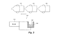
図3を参照して本方法の好適な態様を記述する。図3において、容器302は回転しながら1個または一連の重合体蒸発源(polymer−vaporizing source)304の所を連続的に通り抜ける。前記重合体蒸発源304には、重合体の粒子308が入る溶融−蒸発装置306が含まれており、それは電力源310で加熱される。加熱は例えば放射加熱装置、抵抗加熱装置または本技術分野で公知の他の手段を用いて実施可能である。次に、その蒸発させた重合体が容器302の表面に付着することで、前記容器の表面の上に非常に薄い重合体被膜を形成する。
【0049】
重合体308は、被覆工程の真空条件下で分解を起こすことなく蒸発する重合体である。適切な重合体の例には低分子量のオレフィン、ポリエステルおよびポリプロピレンが含まれる。ポリエチレンが好適な重合体である。被膜の厚みを10から1000nm、より一般的には200nm以下にする。
予備処理および/または後処理
蒸発させた重合体ガス方法および重合性有機ガス方法の両方を主被膜に対する前処理(即ちボトル表面と主被膜の間のアンダーコート)としてか、主被膜に対する後処理(即ち主被膜の上のトップコート)としてか、或は主被膜に対する前処理と後処理の両方として用いてもよい。どちらの方法をプレコートまたはポストコート(post−coat)として用いることができるかに関する重合性ガス方法と重合体ガス方法の間の選択は主に基質および主被膜の種類に依存する。厚いトップコートが有利であり得る極端な取り扱い条件の場合、トップコートを付着させる時に好適な方法は一般に重合体蒸発方法である。しかしながら、2つの方法を互いに組み合わせて用いることも可能であり、その結果として、重合性ガス方法で生じさせたアンダーコートを重合体ガス方法で生じさせたトップコートと組み合わせて用いることも可能である。そのような前処理および後処理工程を有利には本明細書に記述する炭素含有被膜または特許文献1に記述されている如き全体が無機の被膜のいずれかと一緒に適用することができる。
【0050】
薄い重合体被膜を前処理として用いると、その被膜は容器表面と主被膜の間に挟まれ、それによって下記の利点が得られる:(i)フリーラジカルを容器表面に与えることでそれを活性化させ、それによって、主被膜の接着力がより良好になり得ること、(ii)重合体形成ガス(polymer−forming gas)の方が主被膜の無機粒子よりも基質表面の欠陥部の中に良好に流れ込むことからそのような欠陥部がより良好に覆われることで、被膜の中に発生するピンホールの発生率が低くなりかつバリヤーが向上すること、そして(iii)容器表面と主被膜の間に柔らかな層を与えることで主被膜が摩滅および取り扱い誤用に耐える度合を向上させ、それによって、主被膜が取り扱い中に亀裂を起こす傾向が低くなり、従って、取り扱い誤用中に起こるバリヤー損失の度合が低くなること。
【0051】
そのような薄い重合体被膜を後処理として用いると下記の利点が得られる:(i)主被膜の中のピンホールが満たされ、従ってバリヤーが向上すること、(ii)主被膜を亀裂なしに曲げることができかつ膨張させることができるようになることで被膜の柔軟性が向上し、それによって容器が苛酷な条件下で膨張することによって起こるバリヤー損失の度合が低くなること、(iii)主被膜を取り扱い誤用から保護し、従ってボトル詰めプラント、配達または市場条件が原因で起こるバリヤー損失の度合が低下すること、そして(iv)トップコートクッション(topcoat cushioning)を与えることで被膜の脆さを低くし、従って取り扱い誤用および/または容器膨張に対する耐性が向上すること。
【0052】
前記重合性有機ガス方法は、主被膜を付着させることに関して図1を参照して記述した如き主被膜付着方法と組み合わせて前処理または後処理のいずれかとして適用可能である。特定の被覆用途および被膜の種類では、そのような前処理および後処理方法を用いるとバリヤーが向上しかつ取り扱いおよび引き伸ばしに対する耐性が向上することから、主被膜に炭素を含有させる必要がなくなる可能性がある。しかしながら、バリヤーかつ取り扱い耐性に関する要求が高い用途に好適な方法は、少なくとも前処理または後処理または好適には両方と一緒に炭素含有主被膜を付着させる方法である。そのような3種類の方法(即ち前処理、炭素含有主被膜および後処理)は一般に1工程の段階として見なされるべきであり、それらの全部を適用した時に最良の結果が得られる。
IV. プラスチック製容器本体を被覆する一体式システム
被膜を有するプラスチック製容器を製造するシステムは、1つの態様において、真空槽、容器供給装置、コンベヤー、および前記真空槽の中に位置していて被覆用蒸気を供給する少なくとも1種の蒸発装置(即ち被覆源)を含んで成る。前記真空槽はこの真空槽の中に真空を維持する能力を有し、そして前記容器供給装置を用いてプラスチック製容器本体を前記真空槽の中に供給しそして被覆されたプラスチック製容器をそこから取り出す。前記プラスチック製容器本体は各々が外側表面と内部空間部を限定している内側表面を有する。前記コンベヤーを用いて前記プラスチック製容器本体を前記真空槽の中に通して移送し、そして前記容器本体を前記真空槽の中に通して移送しながら、前記少なくとも1種の被覆用蒸気源を用いて被覆用蒸気を前記容器本体の外側表面に供給する。前記少なくとも1種の被覆用蒸気源およびコンベヤーは前記真空槽の中に前記少なくとも1種の源から発生した被覆用蒸気によって前記容器の外側表面の上に薄い被膜が付着するように構成かつ配置されており、ここで、前記薄い被膜は炭素含有無機酸化物とガラス形成金属添加剤を含んで成っていて前記容器本体の外側表面に接着しており、その結果として生じた被膜を有するプラスチック製容器は、これの内部空間部に60psig(4.1バール)の圧力に加圧された流体を入れて密封した時、前記被膜を持たない前記容器の内部空間部に60psig(4.1バール)の圧力に加圧された流体を入れて密封した時に前記被膜を持たない容器が示すガスバリヤーの少なくとも1.25xのガスバリヤーを示す。前記真空槽の中に発生させる被覆用蒸気は望ましくはプラズマの形態である。そのようなプラズマを発生させるに適した装置は冷陰極であり、これはまた電子ガン(electron gun)としても知られる。
【0053】
本明細書に記述する被覆システムの好適な態様を図4に示す。プラスチック製容器本体を炭素含有無機酸化物バリヤー被膜で被覆する高速で高容積の被覆システム400を示す。しかしながら、この高速で高容積のシステム400は、この上に図1を参照して記述したシステムの場合と同じ材料を用いて同じ種類のプラスチック製容器に同じ被膜を付着させる時にも有用である。この高速で高容積のシステム400を特許文献1に記述したシステムの場合と実質的に同じパラメーターの下で操作するが、この被膜システムには本明細書に記述する如き修飾を受けさせる。一般的に記述する高速で高容積の被覆システム400は、プラスチック製容器本体、例えばPET製ボトルなどを真空槽430[これの中に自動連続コンベヤー450および蒸発装置システム440(これは被覆用蒸気源として働く)が入っている]に送り込む自動連続容器供給装置410を含んで成る。炭素含有無機酸化物バリヤー被膜を重合体被膜用の前処理、後処理または前処理と後処理の両方の被膜として用いる場合には、任意の重合体被覆サブシステム(sub−system)420を本被覆システムに組み込むことを示す。
容器供給装置
容器供給装置410は、被覆されていないプラスチック製容器本体をプラスチック製容器本体源から標準的被覆サブシステム420の自動連続コンベヤー424にか或は重合体被覆サブシステム420を省く場合には真空槽の真空槽ハウジングの中に真空を維持しながら真空槽430の中のコンベヤー250に自動的に連続供給する回転式システムであってもよい。この容器供給装置410を用いてプラスチック製容器本体(示していない)を真空槽430に高速および高容積、例えば1時間当たりの容器の数が20,000から60,000の速度で送り込む。また、この容器供給装置410を用いて被覆されたプラスチック製容器本体を重合体被覆サブシステム420のコンベヤー424からか或は真空槽430の中のコンベヤー450から自動的かつ連続的に回収して、その被覆されたプラスチック製容器本体を、被覆システム400の外側のある場所、例えば飲料包装ラインなどに移送する。真空槽430の中に真空を維持し易くする目的でそれと容器供給装置410の接触面の所および場合により容器供給装置410と重合体被覆サブシステム420(これを含める場合)の間の接触面の所に真空ポンプおよび口を位置させて用いてもよい。
【0054】
キャッパー(capper)またはキャッピングデバイス(capping device)を用いて、その被覆されていないプラスチック製容器本体にキャップを付けてキャップで密封した後、それに真空排気をある程度受けさせ、次に真空槽430または重合体被覆サブシステム420の中に移送する。前記キャップは、前記容器本体をコンベヤー450または424に取り付けそして前記容器本体の中の圧力を調節する方法を与えるように、前記容器本体のねじ付き仕上げ部を被覆用蒸気から封鎖する機能を果たす。前記キャップが前記プラスチック製容器本体のねじ付き開口部または造作にしっかりと適合しかつコンベヤー424または450で前記プラスチック製容器本体を磁力担持できるように、前記キャップに鉄金属元素を含有させてもよい。望ましくは、前記プラスチック製容器本体を真空槽430に通して移動させながら、前記容器本体の方が前記真空槽の中のそれを取り巻く環境よりも加圧されるように充分な量の空気を前記プラスチック製容器本体に入れておく。適切な容器供給装置が例えば特許文献1に記述されている。
真空槽
バリヤー被膜被覆過程を真空槽430の中で起こさせる。この真空槽430には真空槽ハウジング(この中に非常に高い真空度を維持する)と蒸発装置システム440が含まれている。この被覆過程を望ましくは前記真空槽ハウジングの中で約1x10⁻⁴ミリバールから約50x10−4ミリバール、より好適には約2x10⁻⁴ミリバールから約10x10−4ミリバールの範囲内の圧力下で起こさせる。前記真空槽430の中に所望の真空度を維持する目的で拡散もしくは真空ポンプを1つ以上用いる。前記真空槽に好適には凝縮装置と低温冷却装置を装備して、真空槽430の中にいくらか存在する水を凝縮凍結させることで、真空ポンプで除去すべき水の量を少なくする。適切な真空槽が例えば特許文献1に記述されている。
コンベヤー
コンベヤー450を用いて、前記容器本体を前記真空槽の中で起こさせる被覆過程に通して移動させる。1つの態様におけるコンベヤーには、前記真空槽の中を縦方向に伸びているレールに沿って滑るように取り付けられる一般にA字型の枠と多数の磁気容器ホルダーが含まれている。コンベヤー450によって前記プラスチック製容器本体が前記被覆用蒸気源の上に担持されるように、前記コンベヤーの枠を被覆用蒸気源、即ち蒸発装置システム440の上に取り付ける。
【0055】
1つの態様におけるコンベヤー枠は、前記容器本体を前記被覆用蒸気源の上に4回、即ち前記容器本体の側面が前記被覆用蒸気源に面するように2回そして前記容器本体の下部が前記被覆用蒸気源に面するように2回運ぶようにエンドレス二重ループ(endless double loop)を形成している。前記容器本体が外側の下方ループに沿って移動している時にはそれの側面が前記被覆用蒸気源に面しそして前記容器本体が内側の上方ループに沿って移動している時には前記容器本体の下部が前記被覆用蒸気源に面する。外側ループに沿ってレールの角度が上方および内側に向くことで容器本体が上方および内側に若干配向し、その結果として、前記容器本体の側面が前記被覆用蒸気源に面するようになる。内側ループに沿ってレールが垂直に配向し、その結果として前記容器本体が実質的に垂直に配向することで前記容器本体の下部が前記被覆用蒸気源に面するようになる。前記容器ホルダーに磁石を含めてもよく、その磁石を用いて、前記プラスチック製容器本体のねじ付き末端部または造作に取り付けたキャップを引き寄せて保持する。その磁力によって前記容器本体が容器ホルダーに被覆工程全体に渡って保持される。前記容器本体を容器ハウジング(container housing)の中に通して移動させながら前記容器ホルダーを用いて前記容器本体を絶えず回転させる。適切なコンベヤーが例えば特許文献1に記述されている。
蒸発装置システム
蒸発装置システム440を用いて主被膜用の被覆用蒸気を発生させる。これは例えば3または4個の蒸発装置を被覆ハウジング(coating housing)の長さに沿って直列に含んで成っていてもよく、それを真空槽430の中のコンベヤー450の下方に位置させる。適切な蒸発装置または(被覆源)はこの上に記述した蒸発装置であり、例えば特許文献1および米国特許第6,251,233号などに記述されている。各蒸発装置には蒸発性材料が入る入れ物(即ちるつぼ)が含まれており、前記入れ物は陽極に電気連結している。各蒸発装置にはまた冷陰極も含まれており、前記冷陰極は好適には真鍮またはマグネシウムを含んで成るが、これはまた他の構成要素、好適にはガラス形成金属添加剤(これは本明細書に記述したように蒸発して前記容器本体を被覆する無機酸化物被膜の一部を形成する)として用いるに有用な金属で作られていてもよい。各蒸発装置には更にプロセスガスと炭素含有ガスを送るガス供給源も含んでいる。
【0056】
適切な手段、例えば誘導もしくは抵抗加熱などを用いて前記入れ物を個別に加熱する。各蒸発装置には陽極を含有するハウジング、蒸発性固体の入れ物および加熱装置、例えば前記入れ物を高温、例えば1200から1800℃の範囲の温度に加熱するに適した炭素フェルト抵抗加熱装置(carbon felt resistance heater)が含まれている。例えばケイ素を入れ物に入れて約1500℃の温度に加熱する。前記入れ物に入れた前記蒸発性材料を更に加熱してプラズマ蒸気を発生させて前記ハウジングの中の開口部に通して放出させる目的でeガン(e−gun)または冷陰極を位置させる。前記蒸発装置を用いて放出させるプラズマ蒸気の被覆角を好適には30から60°にし、そして前記蒸発装置と容器本体の間の距離を好適には0.5から2mにする。前記蒸発装置を前記容器本体に接着しなかった被覆用粒子から保護する目的で好適には前記蒸発装置の上部に粉じん遮蔽装置(dust shield)を含める。
重合体被覆サブシステム
被覆システム400に重合体被覆サブシステム420を組み込んでもよい。それを炭素含有無機酸化物バリヤー用の前処理、後処理または前処理と後処理の両方の被膜として用いる。そのような重合体被覆サブシステムは本質的にプラスチック製容器を被覆するに適した如何なる公知方法であってもよいが、好適には本明細書に記述する重合体被覆方法の1つである。
【0057】
重合体被覆サブシステム420が被覆装置400の中に一体化されていて容器供給装置410と真空槽430の間に位置するように示す。しかしながら、代替態様では、重合体被覆サブシステム420を被覆装置400の上流に位置させることで、被覆されていないプラスチック製容器が容器供給装置410の所に送り込まれる前にそれを重合体層で被覆しておいてもよい(即ち後処理使用)か、或は重合体被覆サブシステム420を被覆システム400の下流に位置させることで、前記プラスチック製容器を覆っている炭素含有無機酸化物バリヤー被覆層の上に重合体層を付着させてもよい(即ち前処理使用)。
【0058】
1つの態様では、重合体被覆サブシステム420と蒸発装置システム440を組み合わせて単一の真空槽の中に位置させ、そして重合体被覆過程と無機被覆過程の両方を通る共通のコンベヤーを用いる。
高速で高容積の被覆システムの操作
一般的に記述するプラスチック製容器本体を容器供給装置410で真空槽430に自動かつ連続的に送り込み、前記容器本体をコンベヤー450で前記真空槽の中に通して前記蒸発装置システムの上に運びそして被覆された容器本体を前記容器供給装置で前記真空槽から取り出すことを通して、前記プラスチック製容器本体に無機酸化物被膜、例えばシリカなどによる被覆を受けさせる。最初に、前記蒸発装置の入れ物に蒸発性無機材料、例えばケイ素などを充填し、真空槽430の中に存在する空気を約2x10⁻⁴ミリバールの圧力になるまで排出させ、そしてプロセスガス、例えば酸素などを適切なガス入り口に通して真空槽430の中に送り込む。
【0059】
被覆されていないプラスチック製容器本体をその源、例えばプラスチック容器ブロー成形ラインなどから容器供給装置410に供給する。その被覆されていない容器本体をコンベヤー450に移送し、そしてそれを排気用磁気キャップ(これは前記容器本体が真空槽430の高真空環境下で若干加圧されたままであることを可能にする)で蓋をする。コンベヤー450の容器ホルダーを磁気で前記容器本体キャップに付着させそして前記容器本体を担持して真空槽430の中の蒸発装置の上方の被覆ハウジングの中を前後に4回移動させる。前記蒸発装置の入れ物の中に入れたケイ素(および/または他の有機材料)を抵抗加熱装置と蒸発装置と関連した冷陰極で加熱することで、蒸発したケイ素と少量の蒸発した金属添加剤、例えば亜鉛、銅またはマグネシウム(これらは前記冷陰極自身から蒸発する)を含んで成るプラズマ蒸気を発生させる。前記容器本体が前記蒸発装置システム440の上を通過する時、前記プラズマ蒸気に入っている材料が前記容器本体の外側表面に付着しそして前記被覆ハウジングの中の酸素と反応することで前記容器本体の外側表面の上に耐久性のある薄い無機酸化物被膜を形成する。前記容器本体のねじ付き開口部または造作にキャップを取り付けておいたことから前記ねじ付き開口部または造作は被覆されないままである。前記真空槽の中を適切な配向で4回通ることで被覆された容器本体を容器供給装置410で取り出し、別のコンベヤー、例えば飲料包装用ラインに向かうコンベヤーに移送し、このラインを用いて、前記被覆を受けさせた容器を飲料で少なくともある程度満たした後、例えばねじ込み型プラスチック製密封具(screw−on plastic closure)などで密封する。
V. 再利用
本明細書に記述する被膜を持たせたプラスチック製容器は特に再利用、例えば化学的または物理的再利用方法で用いるに適する。その被膜材料は有利に不活性であり、当該プラスチック製ボトルを再利用目的で溶融させた時に固体のままである。その被膜は食品接触に関して認可されており、従って、再利用工程で粉砕されるか或は解重合を起こした時でも再利用努力(recycling efforts)に悪影響を与えないであろう。その被膜に用いた粒子は比較的小さいことから、再利用して最終的に生じさせた製品が曇ることを回避することができる。その上、通常のプラスチック再利用方法である熱苛性を用いた洗浄を行うことで前記被膜の全部を除去することができる。本被覆容器はいろいろな種類のプラスチックの再利用に用いることができるが、本被覆容器をプラスチック製品、例えば容器またはボトル、より詳細にはプラスチック製飲料用ボトルと一緒に用いることを意図する。本明細書に記述する被覆容器を用いると有利に被覆されているプラスチックと被覆されていないプラスチックの分類を行う必要がない。ボトルからボトルを生じさせる再利用(bottle−to−bottle recycling)が可能である。
【0060】
本分野の技術者は本明細書に記述した本発明の具体的な態様に対する数多くの均等物を認識するか或はほんの常規実験を用いて確かめることができるであろう。本明細書に引用する文献は引用することによって本明細書に組み入れられる。
【図面の簡単な説明】
【0061】
【図1】
図1は、炭素含有無機被膜(「主被膜」と呼ぶ)を付着させる目的で炭素含有プロセスガスを電気アーク工程において加えることを説明する工程図式図である。
【図2】
図2は、電気アーク工程における前処理(即ち主被膜を付着させる前にアンダーコートを付着させる)または後処理(即ち主被膜を付着させた後にトップコートを付着させる)用ガス流れのプラズマエネルギー供与を説明する工程図式図である。
【図3】
図3は、主被膜を付着させる前のアンダーコートまたは主被膜を付着させた後のトップコートを与える目的で重合体を蒸発させそしてその重合体を容器表面の上で再凝縮させることを説明する工程図式図である。
【図4】
図4は、任意の重合体被覆サブシステムを伴う高速で高容積のバリヤー被覆システムを説明する工程流れ図である。【Technical field】
[0001]
The present invention relates to plastic containers, such as beverage containers, that contain a barrier coating that reduces gas permeability, said barrier coating having a barrier property caused by mishandling and container wall swelling. Shows improved resistance to loss.
[Background Art]
[0002]
Plastic containers constitute a large and growing sector of the food and beverage industry. Plastic containers offer a number of advantages over traditional metal and glass containers. They are lightweight, inexpensive, non-destructive, transparent, and easy to manufacture and handle. However, plastic containers have at least one major drawback, with limited universal acceptance, particularly in more demanding food applications. The disadvantage is that water, oxygen, carbon dioxide and other gases and vapors will more or less permeate any plastic container. In various applications, the permeability of affordable plastics is so high that the shelf life of the food and beverage contained therein is severely limited or no plastic containers can be used.
[0003]
Applying a glass-like or metal-like layer to a plastic container and coating the plastic container with metal to obtain a container structure that combines the best features of plastic containers with more traditional containers Is known. For example, potato chip bags coated with metal have been commercially available for some time. However, in applications where package transparency is of great importance, metallized coatings are unacceptable. It has been found that it is much more difficult to obtain a durable glass-like coating on a plastic container without changing the appearance of the container.
[0004]
Many methods have been developed for forming a soft plastic container from a glass-like coating after the glass-like coating has been deposited on the film. However, it was developed for the purpose of applying a glass-like coating to preformed relatively rigid plastic containers, such as polyethylene terephthalate (PET) bottles commonly used in the United States for carbonated beverages. The method is relatively small, so far it has been sufficiently durable to withstand the effects of pressure on the container, retains an improved barrier to gases and vapors after said pressurization, and No method has been developed to deposit a glass-like coating on the outer surface of a plastic container that does not adversely affect utilization. Currently, pressurized beverage containers make up a very large market on a global scale, but today affordable plastics have extremely high transmittance and various markets where plastic containers are available. Restricts its use.
[0005]
Such pressurized containers include plastic bottles for both carbonated and non-carbonated beverages. Plastic bottles are made of various polymers, especially plastic bottles for carbonated drinks are mainly made of PET. However, such polymers all exhibit varying degrees of permeability to gases and vapors, thus limiting the shelf life of the beverages contained therein. For example, the life of a carbonated beverage bottle is CO2[Shelf life is typically defined as the time it takes for 17 percent of the beverage's initial carbonation to be lost]. The loss rate increases with decreasing bottle size due to the effect of surface to volume ratio. Numerous market applications call for small containers, but in such cases it severely limits the use of plastic bottles. Thus, it would be desirable if a container was obtained that exhibited improved carbonation retention properties.
[0006]
Similar restrictions are imposed on non-carbonated beverages because of the diffusion of oxygen and / or water vapor, and again, the smaller bottles become more important. Diffusion means both entering and leaving a bottle or container (diffusion and intrusion). Under conditions of high ambient temperature, CO2The degree of impermeability to the diffusion of oxygen and to the diffusion of oxygen, water vapor and other gases (referred to herein as "gas barrier") becomes important. It is an alternative to small bottles because having an outer coating showing a high gas barrier attached to a plastic bottle can improve the quality of the beverage it contains and extend the shelf life of the bottle. There is a number of advantages in being more likely to become goods, thereby reducing delivery costs and making the marketing mix more flexible.
[0007]
It would also be desirable if a plastic container, such as a PET bottle, could be reused. However, known barrier-enhanced coatings are often organic and relatively thick, and therefore can contaminate recycled plastic products. It can be used as a container for beverages or foodstuffs, since the mixing of the organic coating material into the recycled plastic can cause the beverage or foodstuff to come into contact with and contaminate such organic coating material. Not suitable for use. In addition, the appearance and properties of the resulting recycled plastic product may be impaired because the relatively thick coating forms relatively large particles when the plastics material is recycled. May be affected. In particular, if relatively large coating particles get into the recycled plastic, the clear plastic can become clouded when it is not. Fogged plastic is often undesirable in containers such as beverage and food containers.
[0008]
In addition, the cost of depositing the coating on the outside of the bottle should not add significantly to the cost of the basic package. This greatly increases the shelf life of the beverage in which the coating is contained in the bottle, greatly reduces product decay of the beverage in the bottle, significantly reduces product rot due to ultraviolet light, and environmental stress cracking. This is true even for gas barriers which substantially eliminate and / or give specific colors. This criterion excludes many methods that attempt to produce coatings that exhibit high gas barriers, because plastic bottles are themselves very low cost, mass-produced products. Because it is. Affordability means that in practice the cost of the coating should not add to the price of the entire package minimally or thereby should not be high, and may actually be lower. Means
[0009]
The coating applied to the outside of the plastic bottle should be flexible. If the bottle is used as a pressurized container, the coating should preferably be able to stretch biaxially whenever the plastic substrate stretches. Preferably, the coating is continuous over most of the surface of the container. Especially in the case of carbonated beverages, the adhesion is important because the CO2Exerts some or all of the pressure in the bottle on the coating. Such pressures can rise to pressures in excess of 6 bar, thereby exerting considerable force on the coating / plastic interface. The coating must also withstand scratches, normal handling, climatic conditions (eg, exposure to rain, sun and temperature fluctuations) and the coating maintains its gas barrier throughout the useful life of the bottle. There must be.
[0010]
There are several plasma-enhanced processes for applying an outer inorganic coating to a range of products, including in some cases bottles. Many such methods are aimed at providing much less cumbersome coating properties that are completely different from bottle coatings which should have a high gas barrier. Such methods, for example, are aimed at abrasion resistance, in which case the continuity of the coating is not a significant factor, since the very fine This is because the gap can be protected. Other methods are for cosmetic or light reflective properties and some have only a role of handling protection. Such substrates are often not bent or stretched, and such products are themselves more expensive than plastic bottles, so that the price is not a design advantage. In some cases, the coating temperatures allowed when using such substrates are much higher than those allowed when using PET, the most common plastic bottle material. It is generally not possible to provide the continuity, adhesion, and flexibility of the coating required to provide a coating that exhibits a high gas barrier with such a method, and the high gas barriers described above have to be used. It does not provide a solution to other problems associated with the coating shown.
[0011]
An electric arc method in which the adhesion of an inorganic coating to a plastic substrate under vacuum is enhanced by a plasma is described in US Pat. A low voltage electric arc is generated between the cooled cathode and the anode, which anode is coated solids [which evaporates with the energy of the arc and is plasma-energized]. Is holding a crucible. One or more reactive gases may be added to the plasma. A dense coating that adheres well is obtained because of the relatively high proportion of high energy particles in the plasma. Using such a method, a plastic container having an outer glass-like barrier coatings is obtained.
[0012]
However, plastic containers for certain applications must withstand conditions that result in a very high degree of handling abuse and / or significant expansion of the plastic substrate. High degrees of mishandling can occur in bottling plants, during delivery and in the marketplace. Examples of such misuse include (i) the use of empty bottle storage rooms and such post-storage bottle sorting / erection devices (whereby the bottles are in contact with each other and metal contact parts). Continuous rubbing, which often has the effect of scratching them severely), (ii) the use of bottle warmers to spray hot water onto the bottles, whereby the surface is hot and wet. Bottles (PET) designed to handle glass containers, which are chemically affected by additives that are exposed to water and are somewhat in the water, such as de-scaling agents. (Not designed to handle containers made exclusively) (such lines Is generally not very friendly to the handling of plastic containers), and (iv) that the containers are delivered over long distances in hot and dusty conditions (as a result of which container-to-container contact and attrition may occur). Cause excessive damage). The conditions that result in significant expansion of the container are generally a combination of high ambient temperature and humidity, especially when the beverage is highly carbonated (due to the high internal pressure of the container handling such beverages), and also This is particularly the case for contoured packages with decorative features (due to weakening of the container walls due to such features). Misuse of the handling and / or conditions that result in significant swelling of the container, as shown in the above examples, can result in excessive damage to the coating, resulting in significant loss of barrier. In such misuses and conditions, the coating design exceeds the coating design measures described in U.S. Pat. No. 6,037,036 to avoid significant loss of barrier at certain market point-of-sale. Measures may be required. In some applications, a stronger coating may be advantageous.
[Patent Document 1]
PCT WO 98/40531
DISCLOSURE OF THE INVENTION
[Problems to be solved by the invention]
[0013]
Accordingly, it is an object of the present invention to provide a barrier coated plastic container and coating thereof with a reduced barrier loss due to conditions that result in abrasion and other mishandling and significant expansion of the plastic substrate. May provide a method.
[0014]
It is another object of the present invention to provide a container, such as a heat sensitive plastic bottle, with an outer coating that has improved resistance to attrition and other mishandling and to conditions that result in significant expansion of the plastic substrate. .
[0015]
It is a further object of the present invention to provide a plastic container with a coating that exhibits an improved barrier as compared to the barrier provided when using the method described in US Pat.
[0016]
It is yet another object of the present invention to provide a flexible, durable, and sufficiently adherent outer glass-like coating that withstands the effects of bending, stretching, dents and abrasion of the container without significant loss of high barrier properties. It is an object of the invention to provide a resulting coating and system and a coating method.
[Means for Solving the Problems]
[0017]
A system for producing a plastic container having a coating exhibiting a gas barrier and having improved resistance to barrier loss due to mishandling and expansion of the container wall. The system comprises (a) a vacuum cell [a vacuum can be maintained in the vacuum chamber], and (b) located in the vacuum chamber and located in the vacuum chamber. At least one coating source for supplying the coating vapor to the outer surface of the plastic container [this coating source heats and evaporates an inorganic coating material such as metal or silicon, etc .; an evaporator for generating a coating vapor, and means for energizing the coating vapor to generate a plasma], and (c) providing one or more process gases to the interior of the vacuum chamber. It comprises gas feeds which supply into the space, usually into the plasma generation region. At least one of the process gases is a carbon-containing gas, preferably a low molecular weight organic gas, such as acetylene, ethylene or ethane. The coating source is placed in the vacuum chamber and the plasma reacts with at least one of the process gases so that a thin coating adheres and adheres to the outer surface of the plastic container, resulting in a thin coating of carbon. And an inorganic material [the inorganic material is, for example, a clear / transparent inorganic oxide]. The use of such a combination of coating components provides a good gas barrier as well as improved resistance to barrier loss.
[0018]
A variety of barrier coatings can be produced depending on the choice of the inorganic material and the carbon-containing gas, such as colorless transparent oxide coatings, opaque or translucent coatings, and colored coatings.
[0019]
The system may also include a container feeder and a conveyor for transferring a number of plastic containers into the vacuum chamber and transferring them through the coating process, preferably in a continuous or semi-continuous mode. Good.
[0020]
In another aspect, the system includes, in addition to a vacuum chamber and at least one primary coating source as described above, (a) supplying one or more process gases into an interior space of the vacuum chamber. A gas supply and (b) at least one polymer located in the same or another vacuum chamber for applying one or more coatings of the polymer to a plastic container located in the vacuum chamber; And a coating source. The main coating source is placed in the vacuum chamber and the plasma reacts with at least one of the process gases (optionally containing a carbon-containing gas) to form a thin coating on the outer surface of the plastic container. Adhering and positioning the resulting thin coating to comprise an inorganic material, such as an inorganic oxide. A polymer coating source in a first type of the present system includes a second gas supply comprising a polymerizable gas and energizing the polymerizable gas to generate a plasma comprising polymerizable free radicals. The polymerizable free radicals adhere to the plastic container and polymerize to form a thin polymer film. Examples of such polymerizable gases include olefins, paraffins, and mixtures thereof. Ethylene and acetylene are preferred. A second type of polymer coating source in the present system comprises a melter-evaporator for heating and evaporating the vaporizable polymer to generate a polymer coating vapor, The polymer coating vapor recondenses on the plastic container and adheres to it to form a thin polymer coating. The evaporable polymer is a polymer that can evaporate without decomposition under vacuum conditions, such as polyolefin, polyester, polycarbonate, or a mixture thereof. Polyethylene is a preferred polymer. In any type of the present system, such a thin polymer coating may be applied as a topcoat, undercoat, or both with respect to the primary inorganic coating. Combining an inorganic coating with a polymer pre-and / or post-coat with or without an optional carbon component provides good gas barrier as well as barrier loss. Improved resistance is obtained.
[0021]
In a preferred embodiment, the plastic container with the coating is coated with four times the volume of carbon dioxide in the internal volume and sealed, even after abuse of handling and severe environmental conditions. Fig. 2 shows a gas barrier of at least 1.25x of the gas barrier shown by the plastic container not provided with.
[0022]
In addition to providing a method for producing a plastic container having a coating based on the present system, the plastic container itself having the coating is also provided. Also provided are beverages and packaging systems packaged therein.
BEST MODE FOR CARRYING OUT THE INVENTION
[0023]
A method and system for coating a container has been developed wherein the coating adheres well to the surface of the container and exhibits a good gas barrier, as well as being required to withstand severe mishandling and expansion of the container wall. Shows attrition resistance, stretchability and flexibility.
[0024]
The coatings exhibit improved resistance to barrier loss due to mishandling and swelling of the container wall, which may include adding a carbon-containing gas to the inorganic process gas used in forming the primary coating and / or Depositing a thin polymer undercoat between the container surface and the main coating using a polymerizable organic gas and / or depositing a thin polymer topcoat on the main coating using a polymerizable organic gas; This has been achieved by using a polymer which evaporates without decomposition under the vacuum conditions of the coating process and results in the deposition of a thin undercoat or topcoat.
[0025]
A container or bottle is described throughout this specification. An uncoated container may be referred to as a container body. Although such container bodies are generally described with reference to plastic bottles, any suitable container may be processed using the methods and systems of the present invention. Accordingly, various sizes of soft drink bottles, other food containers, or any other suitable container can be processed using the methods and systems described herein.
[0026]
As used herein, the term "barrier" refers to the resistance to permeation of gases and vapors, unless otherwise specified.
I.Carbon-containing inorganic coating method and system
A method of incorporating carbon into the inorganic barrier coating described in
[0027]
Such carbon-containing inorganic coatings offer the advantage of being more resistant to barrier loss in addition to being able to provide a high barrier. In one aspect, clear / transparent silicon dioxide coatings ("glass-like" coatings) can be produced that exhibit greatly improved barriers under harsh handling and environmental conditions. For example, such coatings may exhibit improved barriers after being subjected to severe handling misuse in a bottling plant and even after being subjected to harsh environmental conditions that result in significant swelling of the bottle.
Coating system
The method in a preferred embodiment is a method assembled based on the method described in
[0028]
The method should be carried out under vacuum and in a vacuum chamber, for example a vacuum chamber as described in US Pat. The operating pressure of the method when using a carbon-containing gas is 10 to 10 depending on the type of coating.-4From 10-1Millibar range, more usually 10-3From 10-2In the millibar range. The operating pressure when using a carbon-containing gas tends to be higher than the pressure normally used when the inorganic coating does not contain carbon for equal coating rates. Operating parameters in other aspects are within those described in US Pat. No. 6,279,505 and US Pat. No. 6,279,505.
[0029]
The
(1)Carbon containing gas
The carbon-containing
(2)Inorganic coating materials and process gases
The coating material 108 is an inorganic material that is solid at room temperature and has a high boiling point, for example, a boiling point exceeding 500 ° C. Such a coating material may be, for example, a metal, silicon or other non-metal, or the like, or a combination thereof.
[0030]
The addition of various multivalent metal oxides, such as aluminum oxide, to a carbon-containing coating can produce a clear, glassy, clear barrier that can withstand mishandling and environmental conditions. It is particularly advantageous to combine a tetravalent metal, such as titanium, with carbon.
[0031]
The choice of such coating materials and processes depends on process criteria (cost, coating color, transparency, bottle shape, required gas barrier degree, bottle size, especially the type of plastic used in the bottle). Depends on. When no carbon-containing gas is present, the procedure described herein is used to react silicon and oxygen at the surface to produce SiO 2.x[Where x is generally greater than 1.7 and usually slightly less than 2], thus providing a good gas barrier by producing a glass-like transparent coating. When a carbon-containing gas is present, x is smaller because some of the valence sites of silicon are occupied by carbon rather than oxygen, but the same principle applies, with the result that SiOyCz[Where y + z is greater than 1.7 and usually slightly less than 2].
[0032]
Further, Li, Na, K, Rb, Cr, Mg, Ca, Sr, Ba, Ti, Al, Mn, V, Cr, Fe, Co, Ni, Zn, Cu, Sn, Ge and In It is also contemplated to include 0.01 to 50% of one or more glass-forming metal additives selected from the group consisting of: The addition of small or trace amounts of certain metals to silicon dioxide and other coatings can improve gas barrier. Such metals can be described as glass-forming metal additives because they are known as additives used in glass making. Suitable glass forming metal additives include Ag, Al, Ca, Cr, Cu, Fe, K, Mg, Mn, Na, Ni, Sn, Ti and Zn. Such a metal is added so that the ratio of the metal in the coating is 0.01 to 50%. For example, such an additive may be replaced with SiO2When added to the coating mainly composed of the above, the gas barrier is improved by a factor of two or more. Addition of such metals to the crucible or sacrificial erosion of such metals in an electron emitting plate or cathode shield, which is made up of the desired metal or metal mixture Give in.
[0033]
It is also possible to produce colored or UV-absorbing coatings with metals and other gaseous substances (by appropriate choice of reactants). Also, two or more layers, each layer comprising a different composition, can be beneficial, especially when attempting to produce a colored coating, since the colored layer and the transparent layer This is because a good gas barrier with a minimum thickness of the colored film and thus improved reusability can be obtained by combining them. When more than one inorganic coating material is used, it is often necessary to provide more than one coating source because each material present in the coating as a result of a difference in vapor pressure between the materials. This is because fractionation may occur and their ratio may become uncontrollable.
[0034]
In addition, using the systems and methods disclosed herein, plastic container bodies can be made of metal or other inorganic materials, such as silicon (which is an elemental metal rather than an oxide) or other material containing carbon. It is also possible to coat with an inorganic material or the like. For example, by eliminating the amount of reactant gas used in the vacuum chamber other than the carbon-containing gas, the plastic container body can be coated with carbon-containing elemental aluminum or silicon. The carbon-containing gas reacts to produce elemental carbon, but the inorganic material does not react.
[0035]
In another embodiment, a clear / transparent metal oxide coating containing carbon can be produced with a high barrier instead of a silicon dioxide coating. For high barrier applications where transparency is required, such as glass, the first choice is usually silicon dioxide, but metal is much easier to supply continuously to the coating source than silicon. Moreover, the addition of various metals to the selection of available inorganic coating materials broadens the selection of suitable crucible materials. Thus, the use of a metal when forming a carbon-containing metal oxide coating can significantly reduce the cost of forming the coating as compared to a silicon dioxide coating.
[0036]
The source of inorganic material supplied to the crucible can be automated, for example as a rod or other solid structure or any other form. Preferably, the inorganic material is supplied to the crucible in solid form, especially in chunk or non-powder form. By minimizing the surface area of such materials, harmful oxidation effects can be avoided.
[0037]
The choice and use of one or more process gases, such as 118a and 118b, will depend on the particular inorganic coating material and carbon-containing gas used. For example, when the inorganic film is an oxide, the process gas requires oxygen. In an alternative embodiment, the process gas includes an inert gas, such as argon, which can be used to enhance the plasma-energy process.
Operation of the coating system
By positioning the cathode at the negative (negative) pole and the crucible at the positive (positive) pole and connecting the potential across the
[0038]
If a good gas barrier result is to be obtained, a reaction between the coating material and the process gas takes place on the surface after the coating material has adhered to form a solid lattice. This is beneficial because the process gas subsequently reacts to a solid grid, thereby thickening the coating. Similarly, the carbon contained in the carbon-containing gas is integrated into the lattice, thereby increasing the flexibility of the lattice.
[0039]
The distance between the surface of the container body and the crucible is important when trying to prevent the coating material from reacting with the process gas before the coating material adheres to the container surface. Similarly, the condition of the coating material is important when trying to ensure that the reaction taking place on the surface is maximized. The distance is chosen so that the coating source is used optimally and thus can cover as many containers as it can. This distance depends on the degree of vacuum and the deposition rate, but is generally 0.50 m to 2 m. By increasing the distance, a high-energy plasma can be generated at the coating source without causing thermal damage to the container body.
[0040]
The plasma generated in the vacuum chamber can be a high energy plasma, which includes the location of the cathode, the voltage, the distance between the cathode and the crucible, and the coating angle (preferably between 0 and 70 °). Range). The evaporators or coating sources may be arranged in rows such that the evaporator bundles overlap these paths to provide a uniform longitudinal deposition rate R. The speed may typically range from about 1 to 50 nm / sec. In a preferred embodiment, the plastic container is a bottle made of PET about 0.35 mm thick, which has a barrier coating about 50 nm thick.
[0041]
The plastic container is moved while rotating over the coating source (and in the vacuum chamber), which is preferably described in US Pat. Using the equipment and methods described. Provide suitable means for holding and / or transferring the container body through the coating process. This step may be a batch step, or more preferably, is a continuous or semi-continuous step.
[0042]
On some plastic surfaces, it is useful to pre-activate the surface of the plastic container or bottle so that the surface is lightly activated to generate free radicals on the surface. Such a pre-activation can be performed using a process gas, which is applied in the form of a plasma before the coating process starts. The method of applying oxygen or an inert gas as a pre-activation gas and providing them with plasma energy is the method described herein below in connection with FIG. The conditions are the same as those used for coating. For some plastic substrates, it may be useful to keep the surface of the container degassed in order to remove absorbed moisture and low molecular weight materials. Such degassing can be achieved by holding the vessel under vacuum for about 5 to 180 seconds. Although blow molded bottles or containers immediately after blow molding can undergo degassing relatively quickly, locations in the coating process other than at the blow molding machine are more desirable.
II.Plastic container with this coating
The method described herein is preferably used to produce a coated plastic container comprising a plastic container body having an outer surface and having a coating on the outer surface of said container. The coating provides a barrier that restricts the flow of gas into and out of the container, which is particularly useful in the production of carbonated beverages. For example, such a gas barrier coating may protect the beverage by preventing oxygen from flowing into the container from the outside, or may prevent carbon dioxide from escaping from the beverage container. As a result, the shelf life of the carbonated beverage is longer because the coating applied to the container retains carbon dioxide better in the container.
[0043]
The carbon / inorganic coating adheres strongly to the surface of the plastic container, so that even if the coating is discontinuous (e.g., due to scratching or breakage on it), the coating will not adhere to the substrate. , For example, will effectively adhere to the underlying plastic bottle. Thus, the coatings described herein provide an effective gas barrier even when the surface is severely damaged. By using the carbon-containing inorganic coating method described in the present specification, even when a pressurized fluid, for example, a carbonated beverage, is put in a container having the coating, compared to a container not having the coating. A high gas barrier of 1.25x, preferably 1.5x, more preferably 2x can be obtained. Moreover, containers having the coating described herein can be made to have a lighter and equal gas barrier compared to plastic containers having similar surface area and volume but without the outer inorganic coating. is there. The barrier coating in a preferred embodiment of the clear / clear coating comprises a mixture of an inorganic oxide and carbon and optionally a glass-forming metal additive, and the plastic container provided with the coating comprises a When a fluid pressurized to a pressure of 60 psig (4.1 bar) is introduced into the interior space and sealed, a pressure of 60 psig (4.1 bar) is applied to the interior space of the uncoated container. Figure 4 shows a gas barrier of at least 1.25x that of an uncoated container when filled with a pressurized fluid and sealed.
[0044]
The carbon / inorganic coating of the coated plastic container is preferably very thin. The thickness of this coating is preferably from about 1 to about 100 nm.
[0045]
The coated plastic container is manufactured by applying a coating to the outer surface of the container body using vacuum deposition, preferably plasma enhanced vacuum deposition. The resulting coating is preferably substantially uniform and amorphous and adheres chemically, physically or a combination thereof to the outer surface of the container. As used herein, the term "homogeneous" means that there is no substantial variation in the atomic composition through the coating, and the term "amorphous" as measured by standard x-ray diffraction techniques It means that the coating shows substantially no crystallinity. In addition, the components of the coating are preferably present in the coating at a substantially constant concentration throughout the thickness of the coating. For example, for a clear / transparent coating, the inorganic oxide, carbon and glass forming metal additives present in the coating should be present at a substantially constant concentration throughout the coating. Thus, the resulting coating exhibits very high durability.
[0046]
There are a variety of bottle types and coating combinations that can be created. Using the methods and systems described herein, heat-sensitive containers can also be subjected to coating without significant temperature increases, while always keeping the bottle temperature well below 60 ° C. In addition, the method and system can be used to allow the mixture and layer of materials to be deposited to be selected for color, UV absorption properties or additional gas barrier properties. In an exemplary embodiment, the silica or metal oxide coating is sufficiently clear and clear that the appearance of the bottle is not affected when applied to a transparent bottle.
[0047]
Using the coating method described herein, it is also possible to produce plastic containers having color or other characteristics in addition to exhibiting a high barrier to misuse. The carbon-containing coating may be transparent and clear (where the deposit comprises either a carbon and metal oxide or a non-metallic material, such as silicon oxide) or may be opaque or colored. (In this case, the deposit may consist of either carbon and a metal or a non-metal, such as silicon, or an inorganic gas, such as a metal or non-metal compound such as nitrogen). It is also possible to mix visible light absorbing species to incorporate additional functionality into the inorganic coating, thereby making the plastic container more cosmetically attractive. For example, by giving the carbon-containing silicon coating a flickering brown effect, it is possible to give good resistance to transmission of harmful ultraviolet rays. As another example, the carbon-containing metal coating can have a mirror-like metal effect, which can be useful, for example, for use in advertising packaging.
III.Polymer coating method and system
In another aspect of the present invention, the polymer coating is preferably applied to the plastic container in a pre-treatment (undercoat) or post-treatment (overcoat), more preferably both pre-treatment and post-treatment (resulting in a primary inorganic coating Is sandwiched between them). For example, the primary coating may be either the carbon-containing coating described herein or the entirely inorganic coating described in US Pat. The method involves a deposition method that involves introducing a polymerizable organic gas into a plasma-enhanced system or, alternatively, evaporating a polymer that can evaporate without decomposition in a vacuum chamber.
Polymerizable organic gas
A preferred embodiment of the method will be described with reference to FIG. In FIG. 2, the
[0048]
Evaporated polymer gas
A preferred embodiment of the method is described with reference to FIG. In FIG. 3, the
[0049]
The
Pre-processing and / or post-processing
Both the vaporized polymer gas method and the polymerizable organic gas method can be used as a pretreatment for the main coating (i.e., an undercoat between the bottle surface and the main coating) or a post-treatment for the main coating (i.e., the top over the main coating). Coat) or as both a pre-treatment and a post-treatment for the main coating. The choice between the polymerizable gas method and the polymer gas method as to which method can be used as a precoat or post-coat mainly depends on the type of substrate and main coating. For extreme handling conditions where a thick topcoat may be advantageous, the preferred method for applying the topcoat is generally a polymer evaporation method. However, it is also possible to use the two methods in combination with one another, as a result of which the undercoat generated by the polymerizable gas method can be used in combination with the topcoat generated by the polymer gas method. . Such pre- and post-treatment steps can advantageously be applied together with either the carbon-containing coatings described herein or the entirely inorganic coatings as described in US Pat.
[0050]
When a thin polymer coating is used as a pretreatment, the coating is sandwiched between the container surface and the main coating, thereby providing the following advantages: (i) activating it by providing free radicals to the container surface And (ii) polymer-forming gas is better in defects on the substrate surface than inorganic particles of the main coating. Better coverage of such defects due to the flow into the coating reduces the incidence of pinholes in the coating and improves the barrier; and (iii) between the container surface and the main coating. Providing a softer layer increases the degree of resistance of the main coating to abrasion and mishandling, thereby reducing the tendency of the main coating to crack during handling, and That the degree of the barrier loss that occurs during handling misuse is low.
[0051]
The use of such a thin polymer coating as a post-treatment provides the following advantages: (i) filling the pinholes in the main coating and thus improving the barrier; (ii) cracking the main coating without cracking. The ability to bend and expand to increase the flexibility of the coating, thereby reducing the degree of barrier loss caused by the container expanding under harsh conditions; (iii) Protects the coating from mishandling, thus reducing the degree of barrier loss caused by bottling plant, delivery or market conditions, and (iv) reducing the brittleness of the coating by providing topcoat cushioning. Low, thus increasing resistance to mishandling and / or container expansion.
[0052]
The polymerizable organic gas method can be applied as either a pre-treatment or a post-treatment in combination with the main film deposition method as described with reference to FIG. 1 for depositing the main film. For certain coating applications and types of coatings, the use of such pre- and post-treatment methods may improve the barrier and improve handling and stretching resistance, thus eliminating the need for carbon in the main coating There is. However, a preferred method for applications requiring high barrier and handling resistance is to deposit the carbon-containing main coating with at least a pre- or post-treatment, or preferably both. All three of these methods (i.e., pre-treatment, carbon-containing main coating and post-treatment) should generally be considered as one step steps, with the best results being obtained when all of them are applied.
IV.Integral system for coating the plastic container body
In one aspect, a system for producing a coated plastic container comprises, in one aspect, a vacuum vessel, a container feeder, a conveyor, and at least one evaporator located within the vacuum vessel and providing a coating vapor. That is, a coating source). The vacuum chamber has the ability to maintain a vacuum in the vacuum chamber, and a plastic container body is fed into the vacuum chamber using the container feeder and the coated plastic container is removed therefrom. Take out. The plastic container bodies each have an outer surface and an inner surface defining an interior space. The conveyor is used to transfer the plastic container body through the vacuum chamber, and the container body is transferred through the vacuum chamber while using the at least one coating steam source. To supply coating steam to the outer surface of the container body. The at least one coating vapor source and the conveyor are constructed and arranged in the vacuum chamber such that the coating vapor generated from the at least one source deposits a thin coating on the outer surface of the container. Wherein the thin coating comprises a carbon-containing inorganic oxide and a glass-forming metal additive and is adhered to the outer surface of the container body, and the resulting plastic coating has a coating. Is filled with a fluid pressurized to a pressure of 60 psig (4.1 bar), and when sealed, the interior space of the container without the coating has a pressure of 60 psig (4.1 bar). Figure 4 shows a gas barrier of at least 1.25x of the gas barrier exhibited by the uncoated container when a fluid pressurized to pressure is filled and sealed. The coating vapor generated in the vacuum chamber is preferably in the form of a plasma. A suitable device for generating such a plasma is a cold cathode, which is also known as an electron gun.
[0053]
A preferred embodiment of the coating system described herein is shown in FIG. Shown is a high speed, high
Container supply device
The container feeder 410 may be used to transfer the uncoated plastic container body from the plastic container body source to the automatic
[0054]
The uncoated plastic container body is capped and sealed with a cap using a capper or a capping device, and then subjected to some vacuum evacuation, and then to a
Vacuum chamber
The barrier coating process takes place in a
conveyor
Using a
[0055]
In one embodiment, the conveyor frame comprises four portions of the container body above the coating steam source, i.e., two times such that the side of the container body faces the coating steam source, and the lower portion of the container body is An endless double loop is formed to carry the coating twice to face the coating vapor source. When the container body is moving along the outer lower loop, its side faces the coating steam source, and when the container body is moving along the inner upper loop, the lower part of the container body. Faces the coating vapor source. The angle of the rails upward and inward along the outer loop causes the container body to be slightly oriented upward and inward, so that the sides of the container body face the coating vapor source. The rail is vertically oriented along the inner loop, so that the vessel body is oriented substantially vertically such that the lower portion of the vessel body faces the coating vapor source. The container holder may include a magnet that is used to pull and hold a cap attached to a threaded end or feature of the plastic container body. Due to the magnetic force, the container body is held by the container holder throughout the coating process. The container body is constantly rotated using the container holder while moving the container body through a container housing. A suitable conveyor is described, for example, in US Pat.
Evaporator system
An
[0056]
The containers are individually heated using suitable means, such as induction or resistance heating. Each evaporator has a housing containing an anode, a container of evaporable solids and a heating device, such as a carbon felt resistance heater suitable for heating the container to a high temperature, for example, in the range of 1200 to 1800 ° C. heater). For example, silicon is placed in a container and heated to a temperature of about 1500 ° C. An e-gun or cold cathode is positioned to further heat the evaporable material contained in the container to generate plasma vapor and discharge it through an opening in the housing. The coating angle of the plasma vapor emitted using the evaporator is preferably 30 to 60 °, and the distance between the evaporator and the container body is preferably 0.5 to 2 m. A dust shield is preferably included at the top of the evaporator to protect the evaporator from coating particles that have not adhered to the container body.
Polymer coating subsystem
The
[0057]
A
[0058]
In one embodiment, the
Operation of high-speed, high-volume coating systems
A generally described plastic container body is automatically and continuously fed into a
[0059]
The uncoated plastic container body is supplied to the container supply device 410 from its source, for example, a plastic container blow molding line. The uncoated container body is transferred to a
V.Reuse
The coated plastic containers described herein are particularly suitable for reuse, for example, in chemical or physical recycling methods. The coating material is advantageously inert and remains solid when the plastic bottle is melted for reuse. The coating is approved for food contact and will therefore not adversely affect recycling efforts when it is comminuted or undergoes depolymerization in the recycling process. Because the particles used in the coating are relatively small, they can be recycled to avoid fogging the final product. In addition, the entire coating can be removed by washing with hot caustic, which is a common plastic recycling method. Although the present coated containers can be used for recycling various types of plastics, it is intended that the present coated containers be used with plastic products, such as containers or bottles, and more particularly plastic beverage bottles. With the coated containers described herein, it is not necessary to advantageously classify coated and uncoated plastics. Bottle-to-bottle recycling is possible.
[0060]
Those skilled in the art will recognize, or will be able to ascertain using no more than routine experimentation, many equivalents to the specific embodiments of the invention described herein. The references cited herein are hereby incorporated by reference.
[Brief description of the drawings]
[0061]
FIG.
FIG. 1 is a process diagram illustrating the addition of a carbon-containing process gas in an electric arc process for the purpose of depositing a carbon-containing inorganic coating (referred to as a “main coating”).
FIG. 2
FIG. 2 shows plasma energy delivery of a gas stream for pre-treatment (ie, applying an undercoat before depositing the main coating) or post-treatment (ie, depositing the top coat after depositing the main coating) in the electric arc process. FIG.
FIG. 3
FIG. 3 illustrates the evaporation of the polymer and the recondensation of the polymer on the vessel surface for the purpose of providing an undercoat before applying the main coating or a topcoat after applying the main coating. It is process schematic.
FIG. 4
FIG. 4 is a process flow diagram illustrating a high speed, high volume barrier coating system with an optional polymer coating subsystem.
Claims (49)
中に真空を維持することができる真空槽、
前記真空槽の中に位置していてこの真空槽の中に位置させた内部容積を有するプラスチック製容器の外側表面に被覆用蒸気を供給する少なくとも1種の被覆源、および
少なくとも1種が炭素含有ガスである1種以上のプロセスガスを前記真空槽の内部空間部の中に供給する1種以上のガス供給源、
を含んで成っていて、前記少なくとも1種の被覆源が、
無機被覆用材料を加熱しかつ蒸発させて被覆用蒸気を生じさせる蒸発装置、および
前記被覆用蒸気にエネルギーを与えてプラズマを発生させる手段、
を含んで成り、ここで、
前記少なくとも1種の被覆源が前記真空槽の中に前記プラズマが前記プロセスガスの中の少なくとも1種と反応して前記炭素含有ガスに由来する炭素と前記無機被覆用材料に由来する無機材料を含んで成る薄被膜が前記プラスチック製容器の外側表面に付着して接着するように配置されている、
システム。A system for producing a plastic container having a coating exhibiting a gas barrier, comprising:
A vacuum chamber, which can maintain a vacuum inside
At least one coating source for supplying coating steam to an outer surface of a plastic container having an interior volume located within the vacuum chamber and positioned within the vacuum chamber; and at least one carbon-containing source. One or more gas sources for supplying one or more process gases that are gases into the interior space of the vacuum chamber;
Wherein the at least one coating source comprises:
An evaporator for heating and evaporating the inorganic coating material to generate a coating vapor, and a means for applying energy to the coating vapor to generate a plasma;
Where:
The at least one coating source is configured such that, in the vacuum chamber, the plasma reacts with at least one of the process gases to form carbon derived from the carbon-containing gas and an inorganic material derived from the inorganic coating material. A thin film comprising: a thin film comprising:
system.
陽極として電気的に連結していて前記無機被覆用材料の少なくとも一部が入るるつぼ、および
前記被覆用材料を少なくともある程度蒸発させそして前記被覆用蒸気からプラズマを発生させるように前記るつぼの中の前記被覆用材料の前記一部の所に向けられている陰極、
を含んで成る請求項1記載のシステム。The at least one coating source comprises:
A crucible electrically connected as an anode and containing at least a portion of the inorganic coating material, and the crucible in the crucible so as to at least partially evaporate the coating material and generate a plasma from the coating vapor. A cathode directed to said portion of the coating material;
The system of claim 1, comprising:
中に真空を維持することができる1番目の真空槽、
前記1番目の真空槽の中に位置していて前記1番目の真空槽の中に位置させた内部容積を有するプラスチック製容器の外側表面に被覆用蒸気を供給する少なくとも1種の主被覆源、
前記1番目の真空槽の内部空間部の中に1種以上のプロセスガスを供給する1種以上のガス供給源、および
真空を維持することができる2番目の真空槽の中に位置していてこの2番目の真空槽の中に位置させた前記プラスチック製容器の上に1層以上の重合体被膜を加える少なくとも1種の重合体被覆源、
を含んで成っていて、ここで、前記少なくとも1種の主被覆源が、
無機被覆用材料を加熱しかつ蒸発させて主被覆用蒸気を生じさせる蒸発装置、および
前記主被覆用蒸気にエネルギーを与えて主プラズマを発生させる手段、
を含んで成り、そしてここで、前記少なくとも1種の重合体被覆源が、
重合性ガスを含んで成る2番目のガス供給源、および
前記重合性ガスにエネルギーを与えて重合性フリーラジカルを含んで成るプラズマを発生させる手段、
を含んで成り、ここで、
前記少なくとも1種の主被覆源が前記1番目の真空槽の中に前記主プラズマが前記プロセスガスの中の少なくとも1種と反応して前記無機被覆用材料を含んで成る薄い主被膜が前記プラスチック製容器に直接もしくは間接的に付着して接着するように配置されており、そしてここで、
前記少なくとも1種の重合体被覆源が前記2番目の真空槽の中に前記重合性フリーラジカルが前記プラスチック製容器に直接もしくは間接的に付着しかつ重合して前記薄い主被膜とは異なる薄い重合体被膜を形成するように配置されている、
システム。A system for producing a plastic container having a coating exhibiting a gas barrier, comprising:
The first vacuum chamber that can maintain a vacuum inside,
At least one primary coating source for providing coating steam to an outer surface of a plastic container having an interior volume located within the first vacuum chamber and positioned within the first vacuum chamber;
One or more gas sources for supplying one or more process gases into the interior space of the first vacuum chamber, and a second vacuum chamber capable of maintaining a vacuum. At least one polymer coating source for applying one or more polymer coatings on the plastic container positioned in the second vacuum chamber;
Wherein the at least one primary coating source comprises:
An evaporator for heating and evaporating the inorganic coating material to generate a main coating vapor, and a means for applying energy to the main coating vapor to generate a main plasma;
And wherein the at least one polymer coating source comprises:
A second gas source comprising a polymerizable gas, and means for energizing the polymerizable gas to generate a plasma comprising polymerizable free radicals;
Where:
The at least one main coating source is in the first vacuum chamber and the main plasma reacts with at least one of the process gases to form a thin main coating comprising the inorganic coating material. Are arranged to attach and adhere directly or indirectly to the container, and where:
The at least one polymer coating source is provided in the second vacuum chamber with the polymerizable free radicals directly or indirectly attached to the plastic container and polymerized and polymerized free radicals different from the thin main coating. Arranged to form a united coating,
system.
中に真空を維持することができる1番目の真空槽、
前記1番目の真空槽の中に位置しかつ
無機被覆用材料を加熱して蒸発させて主被覆用蒸気を生じさせる蒸発装置、および
前記主被覆用蒸気にエネルギーを与えて主プラズマを発生させる手段、
を含んで成っていて前記1番目の真空槽の中に位置させた内部容積を有するプラスチック製容器の外側表面に被覆用蒸気を供給する少なくとも1種の主被覆源、
前記1番目の真空槽の内部空間部の中に1種以上のプロセスガスを供給する1種以上のガス供給源、および
真空を維持することができる2番目の真空槽の中に位置していてこの2番目の真空槽の中に位置させた前記プラスチック製容器の上に1層以上の重合体被膜を加える少なくとも1種の重合体被覆源、
を含んで成っていて、
前記少なくとも1種の重合体被覆源が、真空条件下で分解を起こすことなく蒸発し得る蒸発性重合体を加熱しかつ蒸発させて重合体被覆用蒸気を生じさせる溶融−蒸発装置を含んで成り、ここで、
前記少なくとも1種の主被覆源が前記1番目の真空槽の中に前記主プラズマが前記プロセスガスの中の少なくとも1種と反応して前記無機被覆用材料を含んで成る薄い主被膜が前記プラスチック製容器に直接もしくは間接的に付着して接着するように配置されており、そしてここで、
前記少なくとも1種の重合体被覆源が前記2番目の真空槽の中に前記重合体被覆用蒸気が再凝縮して前記プラスチック製容器に直接もしくは間接的に付着して前記薄い主被膜とは異なる薄い重合体被膜を形成するように配置されている、
システム。A system for producing a plastic container having a coating exhibiting a gas barrier, comprising:
The first vacuum chamber that can maintain a vacuum inside,
An evaporating device located in the first vacuum chamber and heating and evaporating the inorganic coating material to generate a main coating vapor, and applying energy to the main coating vapor to generate a main plasma ,
At least one primary coating source for supplying coating steam to an outer surface of a plastic container having an interior volume located within said first vacuum chamber, comprising:
One or more gas sources for supplying one or more process gases into the interior space of the first vacuum chamber, and a second vacuum chamber capable of maintaining a vacuum. At least one polymer coating source for applying one or more polymer coatings on the plastic container positioned in the second vacuum chamber;
And contains
The at least one polymer coating source comprises a melt-evaporator that heats and evaporates an evaporable polymer that can evaporate without decomposition under vacuum conditions to produce a polymer coating vapor. ,here,
The at least one main coating source is in the first vacuum chamber and the main plasma reacts with at least one of the process gases to form a thin main coating comprising the inorganic coating material. Are arranged to attach and adhere directly or indirectly to the container, and where:
The at least one polymer coating source is different from the thin main coating because the polymer coating vapor is recondensed in the second vacuum chamber and adheres directly or indirectly to the plastic container. Arranged to form a thin polymer coating,
system.
外側表面を有するプラスチック製容器を中に真空を維持することができる真空槽の中に位置させ、
少なくとも1種が炭素含有ガスである1種以上のプロセスガスを前記真空槽の中に供給し、
前記真空槽の中に位置させた蒸発装置を用いて無機被覆用材料を加熱して蒸発させることで被覆用蒸気を生じさせ、
前記被覆用蒸気にエネルギーを与えてプラズマを発生させ、そして
被覆されたプラスチック製容器を前記真空槽から取り出す、
ことを含んで成り、ここで、
前記プラズマが前記プロセスガスの中の少なくとも1種と反応して前記炭素含有ガスに由来する炭素と前記無機被覆用材料に由来する無機材料を含んで成る薄被膜が前記プラスチック製容器の外側表面に付着するようにする、
方法。A method for producing a plastic container having a coating showing a gas barrier,
Placing a plastic container having an outer surface in a vacuum chamber capable of maintaining a vacuum therein;
Supplying one or more process gases, at least one of which is a carbon-containing gas, into the vacuum chamber;
A coating vapor is generated by heating and evaporating the inorganic coating material using an evaporator positioned in the vacuum chamber,
Energizing the coating vapor to generate a plasma, and removing the coated plastic container from the vacuum chamber;
Where:
The plasma reacts with at least one of the process gases to form a thin film comprising carbon derived from the carbon-containing gas and an inorganic material derived from the inorganic coating material on the outer surface of the plastic container. To adhere,
Method.
外側表面を有するプラスチック製容器を中に真空を維持することができる真空槽の中に位置させ、
1種以上のプロセスガスを前記真空槽の中に供給し、
前記真空槽の中に位置させた蒸発装置を用いて無機被覆用材料を加熱して蒸発させることで被覆用蒸気を生じさせ、
前記被覆用蒸気にエネルギーを与えて1番目のプラズマを発生させ、
重合性ガスを前記真空槽の中に供給し、
前記重合性ガスにエネルギーを与えて重合性フリーラジカルを含んで成る2番目のプラズマを発生させ、そして
被覆されたプラスチック製容器を前記真空槽から取り出す、
ことを含んで成り、ここで、
前記1番目のプラズマが前記プロセスガスの中の少なくとも1種と反応して前記無機被覆用材料に由来する無機材料を含んで成る薄い主被膜が前記プラスチック製容器に付着しそして前記2番目のプラズマに由来する重合性フリーラジカルが前記プラスチック製容器または前記主被膜に直接もしくは間接的に付着しかつ重合することで前記薄い主被膜とは異なる薄い重合体被膜を形成するようにする、
方法。A method for producing a plastic container having a coating showing a gas barrier,
Placing a plastic container having an outer surface in a vacuum chamber capable of maintaining a vacuum therein;
Supplying one or more process gases into the vacuum chamber;
A coating vapor is generated by heating and evaporating the inorganic coating material using an evaporator positioned in the vacuum chamber,
Energizing the coating vapor to generate a first plasma,
Supplying a polymerizable gas into the vacuum chamber,
Energizing the polymerizable gas to generate a second plasma comprising polymerizable free radicals, and removing the coated plastic container from the vacuum chamber;
Where:
The first plasma reacts with at least one of the process gases to deposit a thin main coating comprising an inorganic material derived from the inorganic coating material on the plastic container and the second plasma The polymerizable free radicals derived from are attached directly or indirectly to the plastic container or the main coating and polymerized to form a thin polymer coating different from the thin main coating,
Method.
外側表面を有するプラスチック製容器を中に真空を維持することができる真空槽の中に位置させ、
1種以上のプロセスガスを前記真空槽の中に供給し、
前記真空槽の中に位置させた蒸発装置を用いて無機被覆用材料を加熱して蒸発させることで1番目の被覆用蒸気を生じさせ、
前記1番目の被覆用蒸気にエネルギーを与えてプラズマを発生させ、
真空条件下で分解を起こすことなく蒸発し得る重合体を加熱して蒸発させることで2番目の被覆用蒸気を生じさせ、そして
被覆されたプラスチック製容器を前記真空槽から取り出す、
ことを含んで成り、ここで、
前記プラズマが前記プロセスガスの中の少なくとも1種と反応して前記無機被覆用材料に由来する無機材料を含んで成る薄い主被膜が前記プラスチック製容器に付着しそして前記2番目の被覆用蒸気が再凝縮して前記プラスチック製容器の上に直接もしくは間接的に位置する薄い重合体被膜を形成するようにする、
方法。A method for producing a plastic container having a coating showing a gas barrier,
Placing a plastic container having an outer surface in a vacuum chamber capable of maintaining a vacuum therein;
Supplying one or more process gases into the vacuum chamber;
A first coating vapor is generated by heating and evaporating the inorganic coating material using an evaporator positioned in the vacuum chamber,
Energizing the first coating vapor to generate plasma,
Heating and evaporating a polymer that can evaporate without decomposition under vacuum conditions to produce a second coating vapor, and removing the coated plastic container from the vacuum chamber;
Where:
The plasma reacts with at least one of the process gases to deposit a thin main coating comprising an inorganic material derived from the inorganic coating material on the plastic container and the second coating vapor comprises Recondensing to form a thin polymer coating located directly or indirectly on the plastic container;
Method.
請求項35、37または38記載の方法に従って作られた被膜を有するプラスチック製容器を準備するが、この被膜を有するプラスチック製容器は、内部空間部を限定している内側表面と外側表面を有するプラスチック製容器本体とこの外側表面の上に無機材料と炭素を含んで成っていてガスバリヤーを示す被膜を有し、
前記被膜を有するプラスチック製容器の内部空間部の少なくとも一部を飲料で満たし、そして
前記満たす段階の後に前記被膜を有するプラスチック製容器を密封する、
段階を含んで成る方法。A method of packaging a beverage, comprising:
A plastic container having a coating made according to the method of claim 35, 37 or 38 is provided, the plastic container having a coating having an inner surface and an outer surface defining an interior space. A container body and a coating comprising an inorganic material and carbon on the outer surface thereof, the coating comprising a gas barrier,
Filling at least a portion of the interior space of the coated plastic container with a beverage, and sealing the coated plastic container after the filling step.
A method comprising steps.
請求項1、21または26記載の被膜を有するプラスチック製容器を製造するシステム、
飲料を前記プラスチック製容器に充填する充填装置、および
前記充填段階後に前記プラスチック製容器を密封する密封装置、
を含んで成るシステム。A beverage packaging system,
A system for producing a plastic container having a coating according to claim 1, 21 or 26,
A filling device for filling the plastic container with a beverage, and a sealing device for sealing the plastic container after the filling step;
A system comprising:
外側表面を有するプラスチック製容器を中に真空を維持することができる真空槽の中に位置させ、
前記真空槽の中に位置している蒸発装置を用いて無機被覆用材料を加熱して蒸発させることで被覆用蒸気を生じさせ、
前記被覆用蒸気にエネルギーを与えてプラズマを発生させ、
炭素含有ガスを前記真空槽の中に供給し、そして
被覆されたプラスチック製容器を前記真空槽から取り出す、
ことを含んで成り、ここで、
前記プラズマによって炭素と前記無機被覆用材料を含んで成る薄い無機被膜が前記プラスチック製容器の外側表面に付着するようにする、
方法。A method for producing a plastic container having a coating showing a gas barrier,
Placing a plastic container having an outer surface in a vacuum chamber capable of maintaining a vacuum therein;
A coating vapor is generated by heating and evaporating the inorganic coating material using an evaporator located in the vacuum chamber,
Applying energy to the coating vapor to generate plasma,
Feeding a carbon-containing gas into the vacuum chamber and removing the coated plastic container from the vacuum chamber;
Where:
Causing the plasma to cause a thin inorganic coating comprising carbon and the inorganic coating material to adhere to the outer surface of the plastic container;
Method.
Applications Claiming Priority (2)
| Application Number | Priority Date | Filing Date | Title |
|---|---|---|---|
| US09/843,983 US6599584B2 (en) | 2001-04-27 | 2001-04-27 | Barrier coated plastic containers and coating methods therefor |
| PCT/US2002/012624 WO2002088232A1 (en) | 2001-04-27 | 2002-04-23 | Barrier coated plastic containers |
Publications (2)
| Publication Number | Publication Date |
|---|---|
| JP2004533508A true JP2004533508A (en) | 2004-11-04 |
| JP2004533508A5 JP2004533508A5 (en) | 2005-12-22 |
Family
ID=25291476
Family Applications (1)
| Application Number | Title | Priority Date | Filing Date |
|---|---|---|---|
| JP2002585526A Withdrawn JP2004533508A (en) | 2001-04-27 | 2002-04-23 | Barrier-coated plastic container |
Country Status (7)
| Country | Link |
|---|---|
| US (2) | US6599584B2 (en) |
| EP (1) | EP1385900A1 (en) |
| JP (1) | JP2004533508A (en) |
| BR (1) | BR0209098A (en) |
| CA (1) | CA2444366A1 (en) |
| MX (1) | MXPA03009109A (en) |
| WO (1) | WO2002088232A1 (en) |
Cited By (1)
| Publication number | Priority date | Publication date | Assignee | Title |
|---|---|---|---|---|
| JP2013057111A (en) * | 2011-09-09 | 2013-03-28 | Toppan Printing Co Ltd | Vapor deposition material, gas barrier vapor deposition film and method for producing the vapor deposition film |
Families Citing this family (17)
| Publication number | Priority date | Publication date | Assignee | Title |
|---|---|---|---|---|
| DE10130666A1 (en) * | 2001-06-28 | 2003-01-23 | Applied Films Gmbh & Co Kg | Softcoat |
| DE10153760A1 (en) * | 2001-10-31 | 2003-05-22 | Fraunhofer Ges Forschung | Process for the production of a UV-absorbing transparent abrasion protection layer |
| DE10202311B4 (en) * | 2002-01-23 | 2007-01-04 | Schott Ag | Apparatus and method for the plasma treatment of dielectric bodies |
| US7396563B2 (en) * | 2002-05-23 | 2008-07-08 | Sixtron Advanced Materials, Inc. | Ceramic thin film on various substrates, and process for producing same |
| US20040235680A1 (en) * | 2002-09-18 | 2004-11-25 | Ecolab Inc. | Conveyor lubricant with corrosion inhibition |
| WO2004027001A1 (en) * | 2002-09-18 | 2004-04-01 | Ecolab Inc. | Additive for use in bottle washing compositions additive |
| US6857531B2 (en) * | 2003-01-30 | 2005-02-22 | Plastipak Packaging, Inc. | Plastic container |
| AU2005235601A1 (en) | 2004-04-16 | 2005-11-03 | Advanced Plastics Technologies Luxemboug S.A. | A bottle, a method of forming the bottle, a liquid dispensing system and an extruded profile |
| US20050288191A1 (en) * | 2004-06-24 | 2005-12-29 | Ecolab Inc. | Conveyor system lubricant |
| US20060076715A1 (en) * | 2004-10-07 | 2006-04-13 | Jean-Jacques Katz | Process for creating a low gloss surface finish on a vehicle trim component |
| US9376771B2 (en) * | 2006-11-27 | 2016-06-28 | Mhi Health Devices, Llc | Antimicrobial materials and coatings |
| US7763361B2 (en) * | 2006-12-04 | 2010-07-27 | Sonoco Development, Inc. | Metallized laminated structure and method of making the same |
| DE102007016360A1 (en) | 2007-04-03 | 2008-10-09 | Leibniz-Institut Für Neue Materialien Gemeinnützige Gmbh | Production of scratch-resistant coatings on substrates comprises applying alternating layers of silica and metal oxide using plasma-enhanced chemical vapor deposition |
| US20100129564A1 (en) * | 2007-04-28 | 2010-05-27 | Enerize Corporation | Method for deposition of electrochemically active thin films and layered coatings |
| FR2930121B1 (en) * | 2008-04-18 | 2010-05-21 | Shiseido Int France | PERFUME BOTTLE |
| US10434519B2 (en) | 2011-03-24 | 2019-10-08 | Aamon Ross | Systems and methods for separating refuse |
| WO2016205061A1 (en) * | 2015-06-16 | 2016-12-22 | 3M Innovative Properties Company | Barrier films, vacuum insulation panels and moisture barrier bags employing same |
Family Cites Families (88)
| Publication number | Priority date | Publication date | Assignee | Title |
|---|---|---|---|---|
| US2665226A (en) | 1950-04-27 | 1954-01-05 | Nat Res Corp | Method and apparatus for vapor coating |
| US2664852A (en) | 1950-04-27 | 1954-01-05 | Nat Res Corp | Vapor coating apparatus |
| US2996037A (en) | 1959-01-26 | 1961-08-15 | Nat Res Corp | Vacuum coating apparatus |
| US3016873A (en) | 1959-01-26 | 1962-01-16 | Nat Res Corp | Coating |
| US3511703A (en) | 1963-09-20 | 1970-05-12 | Motorola Inc | Method for depositing mixed oxide films containing aluminum oxide |
| GB1103211A (en) | 1965-01-08 | 1968-02-14 | Mullard Ltd | Improvements in and relating to vapour deposition and evaporation sources |
| US3625848A (en) | 1968-12-26 | 1971-12-07 | Alvin A Snaper | Arc deposition process and apparatus |
| JPS543853A (en) | 1977-06-13 | 1979-01-12 | Onoda Cement Co Ltd | Removing device of excess powder for electrostatidc powder coating |
| JPS5779621A (en) | 1980-11-05 | 1982-05-18 | Mitsubishi Electric Corp | Plasma processing device |
| CH645137A5 (en) | 1981-03-13 | 1984-09-14 | Balzers Hochvakuum | METHOD AND DEVICE FOR EVAPORATING MATERIAL UNDER VACUUM. |
| JPS57169088A (en) | 1981-04-09 | 1982-10-18 | Olympus Optical Co Ltd | Crucible |
| US4532196A (en) | 1982-01-25 | 1985-07-30 | Stanley Electric Co., Ltd. | Amorphous silicon photoreceptor with nitrogen and boron |
| DE3239131A1 (en) | 1982-10-22 | 1984-04-26 | Ulrich 8950 Kaufbeuren Goetz | Process for the thermal vaporisation of metals in vacuo |
| JPS59128281A (en) | 1982-12-29 | 1984-07-24 | 信越化学工業株式会社 | Manufacture of silicon carbide coated matter |
| GB2139647B (en) | 1983-02-24 | 1986-11-19 | Boc Group Plc | Bottle coated ion-plating or magnetron sputtering |
| US4573429A (en) | 1983-06-03 | 1986-03-04 | Nordson Corporation | Process for coating substrates with aqueous polymer dispersions |
| US4552791A (en) | 1983-12-09 | 1985-11-12 | Cosden Technology, Inc. | Plastic container with decreased gas permeability |
| US5096558A (en) | 1984-04-12 | 1992-03-17 | Plasco Dr. Ehrich Plasma - Coating Gmbh | Method and apparatus for evaporating material in vacuum |
| DE3413891A1 (en) | 1984-04-12 | 1985-10-17 | Horst Dipl.-Phys. Dr. 4270 Dorsten Ehrich | METHOD AND DEVICE FOR EVAPORATING MATERIAL IN VACUUM |
| US4634605A (en) | 1984-05-23 | 1987-01-06 | Wiesmann Harold J | Method for the indirect deposition of amorphous silicon and polycrystalline silicone and alloys thereof |
| US4615916A (en) | 1984-06-25 | 1986-10-07 | Owens-Illinois, Inc. | Surface treatment of glass containers |
| JPS61104075A (en) | 1984-10-23 | 1986-05-22 | Hironobu Sato | Device for controlling ionizing vaporization velocity |
| US4752426A (en) | 1985-06-27 | 1988-06-21 | Yoshito Ikada | Process for manufacture of plastic resinous tubes |
| US4697974A (en) | 1986-01-24 | 1987-10-06 | Trimedia Corporation | Pallet-loading system |
| DE3623970A1 (en) | 1986-07-16 | 1988-01-28 | Leybold Heraeus Gmbh & Co Kg | TRANSPORTATION DEVICE WITH ROLLER SYSTEMS FOR VACUUM COATING SYSTEMS |
| US4902531A (en) | 1986-10-30 | 1990-02-20 | Nihon Shinku Gijutsu Kabushiki Kaisha | Vacuum processing method and apparatus |
| US5215640A (en) | 1987-02-03 | 1993-06-01 | Balzers Ag | Method and arrangement for stabilizing an arc between an anode and a cathode particularly for vacuum coating devices |
| EP0285745B1 (en) | 1987-03-06 | 1993-05-26 | Balzers Aktiengesellschaft | Process and apparatus for vacuum coating by means of an electric arc discharge |
| NL8700620A (en) | 1987-03-16 | 1988-10-17 | Hauzer Holding | CATHODE ARC VAPORIZATION DEVICE AND METHOD FOR ITS OPERATION. |
| JPS63243264A (en) | 1987-03-31 | 1988-10-11 | Matsushita Electric Ind Co Ltd | Apparatus for producing thin film |
| JPS63312968A (en) | 1987-06-15 | 1988-12-21 | Hitachi Ltd | Melting and evaporating device |
| US4888199A (en) | 1987-07-15 | 1989-12-19 | The Boc Group, Inc. | Plasma thin film deposition process |
| DE3731444A1 (en) | 1987-09-18 | 1989-03-30 | Leybold Ag | DEVICE FOR COATING SUBSTRATES |
| DE3731686A1 (en) | 1987-09-21 | 1989-04-06 | Leybold Ag | METHOD AND DEVICE FOR PRODUCING A CORROSION-RESISTANT LAYER ON THE SURFACE OF WORK PIECES COATED WITH PAINT |
| JPH01268859A (en) | 1988-04-20 | 1989-10-26 | Casio Comput Co Ltd | Formation of transparent conductive film and device therefor |
| JPH02118064A (en) | 1988-10-27 | 1990-05-02 | Mitsubishi Heavy Ind Ltd | Vacuum deposition device |
| JPH0336258A (en) | 1989-06-30 | 1991-02-15 | Jeol Ltd | Formation of film of inorganic material on plastics |
| DD286375A5 (en) | 1989-08-04 | 1991-01-24 | ��@���������@�������k�� | ARC DISCHARGE EVAPORATOR WITH SEVERAL EVAPORATOR TILES |
| JP2726118B2 (en) | 1989-09-26 | 1998-03-11 | キヤノン株式会社 | Deposition film formation method |
| JPH07110991B2 (en) | 1989-10-02 | 1995-11-29 | 株式会社日立製作所 | Plasma processing apparatus and plasma processing method |
| JPH0733576B2 (en) | 1989-11-29 | 1995-04-12 | 株式会社日立製作所 | Sputter device, target exchanging device, and exchanging method thereof |
| US5112644A (en) | 1990-03-08 | 1992-05-12 | Optical Coating Laboratory, Inc. | Horizontal precession tooling and method for tube rotation |
| CA2040638A1 (en) | 1990-04-20 | 1991-10-21 | Gedeon I. Deak | Barrier materials useful for packaging |
| US5084356A (en) | 1990-04-20 | 1992-01-28 | E. I. Du Pont De Nemours And Company | Film coated with glass barrier layer with metal dopant |
| US5085904A (en) | 1990-04-20 | 1992-02-04 | E. I. Du Pont De Nemours And Company | Barrier materials useful for packaging |
| DE4114108C1 (en) | 1991-04-30 | 1991-12-19 | Schott Glaswerke, 6500 Mainz, De | |
| JPH0448515A (en) | 1990-06-14 | 1992-02-18 | Hitachi Aic Inc | Manufacture transparent conductive film |
| DE4026494A1 (en) | 1990-08-22 | 1992-02-27 | Ehrich Plasma Coating | DEVICE FOR EVAPORATING MATERIAL BY VACUUM ARC DISCHARGE AND METHOD |
| DE4100541C1 (en) | 1991-01-10 | 1992-01-16 | Plasco Dr. Ehrich Plasma-Coating Gmbh, 6501 Heidesheim, De | |
| DE59202116D1 (en) | 1991-04-23 | 1995-06-14 | Balzers Hochvakuum | Process for removing material from a surface in a vacuum chamber. |
| ES2086667T3 (en) | 1991-10-03 | 1996-07-01 | Becton Dickinson Co | TUBE FOR COLLECTING BLOOD. |
| EP0812779B1 (en) | 1991-12-26 | 2000-08-09 | Toyo Boseki Kabushiki Kaisha | A gas barrier film |
| DE4200429A1 (en) | 1992-01-10 | 1993-07-15 | Ehrich Plasma Coating | METHOD FOR IONIZING THERMALLY PRODUCED MATERIAL STEAMS AND DEVICE FOR IMPLEMENTING THE METHOD |
| GB2263472B (en) | 1992-01-14 | 1995-09-06 | Stalplex Limited | Handling and processing plastics bottles |
| CH689767A5 (en) | 1992-03-24 | 1999-10-15 | Balzers Hochvakuum | Process for Werkstueckbehandlung in a Vakuumatmosphaere and vacuum treatment system. |
| MX9303141A (en) | 1992-05-28 | 1994-04-29 | Polar Materials Inc | METHODS AND DEVICES FOR DEPOSITING BARRIER COATINGS. |
| US5308649A (en) | 1992-06-26 | 1994-05-03 | Polar Materials, Inc. | Methods for externally treating a container with application of internal bias gas |
| US5462779A (en) | 1992-10-02 | 1995-10-31 | Consorzio Ce.Te.V. Centro Tecnologie Del Vuoto | Thin film multilayer structure as permeation barrier on plastic film |
| US5641559A (en) | 1992-10-23 | 1997-06-24 | Toyo Seikan Kaisha, Ltd. | Gas-tight laminated plastic film containing polymer of organosilicic compound |
| US5670224A (en) | 1992-11-13 | 1997-09-23 | Energy Conversion Devices, Inc. | Modified silicon oxide barrier coatings produced by microwave CVD deposition on polymeric substrates |
| DE59406143D1 (en) | 1993-06-01 | 1998-07-09 | Buck Chem Tech Werke | METHOD FOR PRODUCING A POLYMER COATING ON PLASTIC HOLLOW BODIES |
| JPH0794421A (en) | 1993-09-21 | 1995-04-07 | Anelva Corp | Manufacture of amorphous silicon thin film |
| US5364666A (en) | 1993-09-23 | 1994-11-15 | Becton, Dickinson And Company | Process for barrier coating of plastic objects |
| US5440446A (en) | 1993-10-04 | 1995-08-08 | Catalina Coatings, Inc. | Acrylate coating material |
| WO1995010117A1 (en) * | 1993-10-04 | 1995-04-13 | Catalina Coatings, Inc. | Cross-linked acrylate coating material useful for forming capacitor dielectrics and oxygen barriers |
| CH687601A5 (en) | 1994-02-04 | 1997-01-15 | Tetra Pak Suisse Sa | Process for the production of internally sterile packaging with excellent barrier properties. |
| US5565248A (en) | 1994-02-09 | 1996-10-15 | The Coca-Cola Company | Method and apparatus for coating hollow containers through plasma-assisted deposition of an inorganic substance |
| ES2131810T5 (en) | 1994-02-16 | 2004-02-16 | The Coca-Cola Company | HOLLOW CONTAINERS WITH INERT OR WATERPROOF INTERIOR SURFACES PRODUCED BY SURFACE REACTION ASSISTED BY PLASMA OR POLYMERIZATION ON THE SURFACE. |
| US5571470A (en) | 1994-02-18 | 1996-11-05 | The Coca-Cola Company | Method for fabricating a thin inner barrier layer within a preform |
| US5521351A (en) | 1994-08-30 | 1996-05-28 | Wisconsin Alumni Research Foundation | Method and apparatus for plasma surface treatment of the interior of hollow forms |
| US5510155A (en) | 1994-09-06 | 1996-04-23 | Becton, Dickinson And Company | Method to reduce gas transmission |
| JPH0892764A (en) | 1994-09-22 | 1996-04-09 | Nec Kyushu Ltd | Sputtering device |
| DE4444763C2 (en) | 1994-12-19 | 1996-11-21 | Apvv Angewandte Plasma Vakuum | Electrode for material evaporation for the coating of substrates |
| DE19600993A1 (en) | 1995-01-13 | 1996-08-08 | Technics Plasma Gmbh | Appts. for high rate anodic evapn. for substrate coating |
| DE19546827C2 (en) | 1995-12-15 | 1999-03-25 | Fraunhofer Ges Forschung | Device for generating dense plasmas in vacuum processes |
| US5558720A (en) | 1996-01-11 | 1996-09-24 | Thermacore, Inc. | Rapid response vapor source |
| EP0785291A1 (en) | 1996-01-19 | 1997-07-23 | The Boc Group, Inc. | Electron beam evaporation system |
| US5691007A (en) | 1996-09-30 | 1997-11-25 | Becton Dickinson And Company | Process for depositing barrier film on three-dimensional articles |
| US6223683B1 (en) * | 1997-03-14 | 2001-05-01 | The Coca-Cola Company | Hollow plastic containers with an external very thin coating of low permeability to gases and vapors through plasma-assisted deposition of inorganic substances and method and system for making the coating |
| US6224948B1 (en) * | 1997-09-29 | 2001-05-01 | Battelle Memorial Institute | Plasma enhanced chemical deposition with low vapor pressure compounds |
| DE19807032A1 (en) | 1998-02-19 | 1999-08-26 | Leybold Systems Gmbh | Vapor coating of cylindrical substrates e.g. silicon dioxide coating for sealing plastic carbonated drinks bottles |
| FR2776540B1 (en) * | 1998-03-27 | 2000-06-02 | Sidel Sa | BARRIER-EFFECT CONTAINER AND METHOD AND APPARATUS FOR ITS MANUFACTURING |
| JP4073540B2 (en) | 1998-04-14 | 2008-04-09 | 株式会社アルバック | Water repellent member and manufacturing method thereof |
| US20010042510A1 (en) | 1998-07-08 | 2001-11-22 | The Coca-Cola Company | Hollow containers with inert or impermeable inner surface through plasma-assisted surface reaction or on-surface polymerization |
| TW372674U (en) * | 1998-07-21 | 1999-10-21 | Cotron Corp | Earphone storage case |
| US6251233B1 (en) | 1998-08-03 | 2001-06-26 | The Coca-Cola Company | Plasma-enhanced vacuum vapor deposition system including systems for evaporation of a solid, producing an electric arc discharge and measuring ionization and evaporation |
| SE520491C2 (en) * | 1999-04-07 | 2003-07-15 | Tetra Laval Holdings & Finance | Packaging laminate with barrier properties against gas and flavorings |
| JP2001261075A (en) | 2000-03-17 | 2001-09-26 | Toppan Printing Co Ltd | Plastic container |
-
2001
- 2001-04-27 US US09/843,983 patent/US6599584B2/en not_active Expired - Fee Related
-
2002
- 2002-04-23 JP JP2002585526A patent/JP2004533508A/en not_active Withdrawn
- 2002-04-23 WO PCT/US2002/012624 patent/WO2002088232A1/en not_active Application Discontinuation
- 2002-04-23 MX MXPA03009109A patent/MXPA03009109A/en unknown
- 2002-04-23 CA CA002444366A patent/CA2444366A1/en not_active Abandoned
- 2002-04-23 BR BR0209098-8A patent/BR0209098A/en not_active IP Right Cessation
- 2002-04-23 EP EP02766790A patent/EP1385900A1/en not_active Withdrawn
-
2003
- 2003-06-26 US US10/609,175 patent/US20030233980A1/en not_active Abandoned
Cited By (1)
| Publication number | Priority date | Publication date | Assignee | Title |
|---|---|---|---|---|
| JP2013057111A (en) * | 2011-09-09 | 2013-03-28 | Toppan Printing Co Ltd | Vapor deposition material, gas barrier vapor deposition film and method for producing the vapor deposition film |
Also Published As
| Publication number | Publication date |
|---|---|
| US6599584B2 (en) | 2003-07-29 |
| CA2444366A1 (en) | 2002-11-07 |
| MXPA03009109A (en) | 2004-02-12 |
| BR0209098A (en) | 2004-07-06 |
| WO2002088232A1 (en) | 2002-11-07 |
| US20020172763A1 (en) | 2002-11-21 |
| EP1385900A1 (en) | 2004-02-04 |
| US20030233980A1 (en) | 2003-12-25 |
Similar Documents
| Publication | Publication Date | Title |
|---|---|---|
| JP2004533508A (en) | Barrier-coated plastic container | |
| US6279505B1 (en) | Plastic containers with an external gas barrier coating | |
| AU659681B2 (en) | Barrier properties for polymeric containers | |
| JPH05345383A (en) | Gas barrier laminated plastic material | |
| AU2013278072B2 (en) | Deposition of ultra-thin inorganic oxide coatings on packaging | |
| US6027793A (en) | Packaging film | |
| JP2007210262A (en) | Transparent barrier film and its manufacturing method | |
| US20130340673A1 (en) | Deposition of ultra-thin inorganic oxide coatings on packaging | |
| JPH0732531A (en) | Gas blocking plastic material provided with transparent membrane composed of silicon compound and production thereof | |
| JP5034258B2 (en) | Transparent deposited film and method for producing the same | |
| JP6852304B2 (en) | Transparent gas barrier film | |
| JPH11256333A (en) | Production method of barrier layer for gaseous and/or liquid substance on supporting body and the such barrier layer | |
| AU2002307469A1 (en) | Barrier coated plastic containers | |
| JP2006045658A (en) | Apparatus for manufacturing gas impermeable layer, and manufacturing method therefor | |
| MXPA99008065A (en) | Plastic containers with an external gas barrier coating | |
| EP2864521A2 (en) | Deposition of ultra-thin inorganic oxide coatings on packaging | |
| AU2013277995A1 (en) | Deposition of ultra-thin inorganic oxide coatings on packaging | |
| WO2013192560A1 (en) |
Legal Events
| Date | Code | Title | Description |
|---|---|---|---|
| A521 | Written amendment |
Free format text: JAPANESE INTERMEDIATE CODE: A523 Effective date: 20050303 |
|
| A621 | Written request for application examination |
Free format text: JAPANESE INTERMEDIATE CODE: A621 Effective date: 20050303 |
|
| A761 | Written withdrawal of application |
Free format text: JAPANESE INTERMEDIATE CODE: A761 Effective date: 20061102 |