JP2004528126A - Replaceable catheter - Google Patents
Replaceable catheter Download PDFInfo
- Publication number
- JP2004528126A JP2004528126A JP2002592991A JP2002592991A JP2004528126A JP 2004528126 A JP2004528126 A JP 2004528126A JP 2002592991 A JP2002592991 A JP 2002592991A JP 2002592991 A JP2002592991 A JP 2002592991A JP 2004528126 A JP2004528126 A JP 2004528126A
- Authority
- JP
- Japan
- Prior art keywords
- catheter
- distal
- proximal end
- distal end
- access
- Prior art date
- Legal status (The legal status is an assumption and is not a legal conclusion. Google has not performed a legal analysis and makes no representation as to the accuracy of the status listed.)
- Pending
Links
Images


Classifications
-
- A—HUMAN NECESSITIES
- A61—MEDICAL OR VETERINARY SCIENCE; HYGIENE
- A61M—DEVICES FOR INTRODUCING MEDIA INTO, OR ONTO, THE BODY; DEVICES FOR TRANSDUCING BODY MEDIA OR FOR TAKING MEDIA FROM THE BODY; DEVICES FOR PRODUCING OR ENDING SLEEP OR STUPOR
- A61M25/00—Catheters; Hollow probes
- A61M25/10—Balloon catheters
- A61M25/104—Balloon catheters used for angioplasty
-
- A—HUMAN NECESSITIES
- A61—MEDICAL OR VETERINARY SCIENCE; HYGIENE
- A61M—DEVICES FOR INTRODUCING MEDIA INTO, OR ONTO, THE BODY; DEVICES FOR TRANSDUCING BODY MEDIA OR FOR TAKING MEDIA FROM THE BODY; DEVICES FOR PRODUCING OR ENDING SLEEP OR STUPOR
- A61M25/00—Catheters; Hollow probes
- A61M25/01—Introducing, guiding, advancing, emplacing or holding catheters
- A61M2025/0183—Rapid exchange or monorail catheters
Abstract
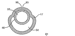
カテーテルシャフトの全長の多くの部分にわたって延びる細長い部品を受容するルーメン(37)を有し、細長い部品を受容するルーメンへおよび細長い部品を受容するルーメンから細長い部品(40)を操作するためのアクセス(78)を有する管状のカテーテルシャフト(16)を含む、血管内バルーンカテーテル(13)を提供する。A lumen (37) for receiving an elongate component extending over a substantial portion of the length of the catheter shaft, and access for manipulating the elongate component (40) to and from the lumen for receiving the elongate component (40). An intravascular balloon catheter (13) is provided that includes a tubular catheter shaft (16) having (78).
Description
【技術分野】
【0001】
発明の背景
1.発明の分野
本発明は概して医療用の器具および方法に関する。より具体的には、本発明は交換可能なバルーン構造を有するバルーンカテーテルに関する。
【背景技術】
【0002】
2.背景技術の説明
経皮経管的血管形成術は、患者の血管、特に冠動静脈の狭窄部位の治療において第一選択の治療法となっている。近年では、このような血管形成術は、施術後の再狭窄および過形成を防ぐため、ステント留置および/または放射線治療と組み合わせて使用されることが多くなっている。このように複数の連続的な治療を行う際は、各手技について使用されるカテーテルを「交換」する必要があるのが普通である。すなわち、最初の血管形成術は血管形成用バルーンカテーテルを用いて行われる。血管形成術の完了後は、ステントまたはその他の血管補綴材を運ぶ第二のカテーテルを治療部位まで導入する必要がある。第二のカテーテルの導入には、まず血管形成用バルーンカテーテルを除去し、次に第二のカテーテルを治療部位に配置することが必要である。選択的に、過形成を防ぐ目的で放射線照射またはその他の治療を行うため、第二のカテーテルをさらに第三のカテーテルに交換する場合もある。
【0003】
このような複数の連続的な治療を行う場合、多くの医師は治療部位に「ガイドワイヤ」を留置しておくことを好む。ガイドワイヤは、血管を通して標的部位まで進めることが可能な、直径が小さく非常に可撓性の高いワイヤであり、標的部位まで進めた後は血管形成用バルーンカテーテルおよびその他の介入用カテーテルを導入および位置決めするための誘導経路として機能する。
【0004】
初期には、血管形成用バルーンカテーテルは「ワイヤ上」方式で血管内に導入するよう設計されていた。すなわち、カテーテルの遠位端から近位端までの全長にわたる、通常ガイドワイヤルーメンと呼ばれるアクセス(access)をもつよう設計された。このカテーテルは、すでに患者に留置されたガイドワイヤの近位端に装填し、カテーテルの遠位端が標的部位に達するまでガイドワイヤ上を前進せしめることが可能であった。この方法は機能的ではあるものの、介入用カテーテルの導入中もガイドワイヤを制御できる必要があり、このことは、患者の体外に出ているガイドワイヤが導入するカテーテルより長くなければならないことを意味していた。長さが少しでも短ければ、術者はカテーテルの導入中にガイドワイヤを保持していることができなくなる。カテーテル導入上必要とはいえ、ガイドワイヤの長さが(選択的に、取り外し可能な延長部分の形態で)長いことは、カテーテル操作以外の治療過程における取り扱いを困難にしていた。
【0005】
長いガイドワイヤに伴う難点を克服するため、「迅速交換式」または「モノレール式」の血管形成カテーテルが開発された。何年間にもわたって専用の設計が多数開発された。迅速交換カテーテルは一般的に、カテーテルの遠位端から、カテーテルの近位端より遠位端に近い位置に配置された出口ポートまでにわたる、短いガイドワイヤルーメンを有する。ガイドワイヤルーメンの長さを短くすることにより、患者の体外に出ているガイドワイヤの長さも短くてすむ。
【0006】
迅速交換カテーテルは広く普及し、特にステント留置カテーテルとして有用であると認められている。ステント留置カテーテルは普通、最初に血管形成術を行った後に使用される。このような場合は、血管形成カテーテルが除去され、ステント留置カテーテルに交換される。迅速交換設計の血管形成カテーテルを使用することにより、短いガイドワイヤで血管形成カテーテルを除去することが容易になる。同様に、迅速交換設計のステント留置カテーテルを使用することにより、患者の体内に留置されたままのガイドワイヤ上でカテーテルを導入することが容易になる。
【0007】
迅速交換カテーテルは広く受け入れられているものの、多数の制限もある。特に、ガイドワイヤルーメンが短いことにより、カテーテルの「押し進めやすさ」が損なわれている。
【0008】
迅速交換カテーテルの使用に伴う第二の問題点は、短いガイドワイヤルーメン内へガイドワイヤを交換または再導入できないことである。
【0009】
これらの理由から、短いガイドワイヤ上でカテーテルおよびカテーテル部品を交換できるような、改善された器具、方法、およびキットを提供することは望ましいと考えられる。特に、血管内へ導入する際の「押し進めやすさ」がより優れ、且つ、短いガイドワイヤ上でのカテーテル除去が可能であるようなおよび/またはガイドワイヤ上に留置されたカテーテル本体上でカテーテル部品の交換が可能であるような、改善された血管形成用バルーンカテーテルおよびその他のカテーテルを提供することは望ましいと考えられる。これらの目的のうち少なくともいくつかは、本明細書の後に記載される特許請求の範囲で記載される本発明により実現される。
【発明の開示】
【0010】
発明の概要
本発明は体内器具および其れを使用する方法を対象とし、より具体的にはバルーンカテーテルを含むカテーテルなどの管腔内器具を対象とする。本発明の器具は診断用途および/または治療用途に使用可能である。本発明は、患者の血管など、患者の身体の様々な位置において種々の状態を治療するのに適している。具体的には、本発明の器具は患者の心臓、末梢、および脳領域の血管内においてバルーン拡張(特に血管形成)、ステント留置などであるがこれらに限定されない手法に基づく事実上あらゆる治療モダリティに使用できる。
【0011】
本明細書において、「体内部分(intracorporeal body)」という用語は、体内の管腔、または、身体内の組織および臓器を意味する。体内の管腔は、静脈、動脈、大動脈、ならびに、特に冠動脈および末梢動脈を含む患者の血管系の任意の血管であってよく、または、以前に留置された移植片、シャント、瘻孔などであってもよい。本発明はまた、新生物性の過剰な細胞増殖が起こりうる、胆管など他の体内管腔に使用してもよく、このことは理解されるものと思われる。体内の組織および臓器の例としては種々の臓器、神経、腺、管などがある。
【0012】
1つの態様において、本発明の血管内カテーテルは治療用または診断用の構造を含む。1つの態様において、治療用または診断用の構造はバルーン構造である。以後、バルーンカテーテルについて本発明の種々の特徴および態様をさらに説明するが、これは本発明の範囲を限定するものではない。
【0013】
1つの態様において本発明の器具は、近位端および遠位端、近位部分および遠位部分を有する細長のカテーテルシャフト、ならびにその細長のシャフトの遠位部分に配置され、そこにシーリング式に固定される膨張部品(例えばバルーン)のような拡張可能部品などの診断用または治療用の構造とを含む、血管内カテーテルである。膨張ルーメンなど少なくとも1つのルーメンは、カテーテルシャフトの少なくとも一部分に沿って延びる。ある態様において、膨張ルーメンはカテーテルシャフトの遠位端に対して近位側の位置で終端し、バルーンの内側と流体接触状態にある。カテーテルシャフトは一体構造であってもよく、または、長手方向に流体接続が可能な複数の部分から形成されていてもよい。
【0014】
1つの態様において、カテーテルシャフトは、近位端と遠位端とを有するシャフトの少なくとも一部に沿って延びる細長部品受容ルーメンであって、管状体、ガイドワイヤ、または管状体内に配置されたガイドワイヤなどを滑動可能且つ取り外し可能な状態で受けるまたはこれらの上で受け取られるような細長部品受容ルーメンをさらに含む。1つの態様において、細長部品受容ルーメンは、シャフトの遠位端部の遠位ポートまで延びる。細長部品受容ルーメンの近位端は、カテーテルシャフトの長さ方向に沿った位置に配置されていてもよく、この位置としては、カテーテルシャフトの近位端部;カテーテルシャフトの近位端に対して遠位側であり、シャフトの遠位端よりシャフトの近位端に実質的に近い位置;カテーテルシャフトの近位端に対して遠位側であり、シャフトの近位端および遠位端からの距離が実質的に等しい位置;カテーテルシャフトの近位端に対して遠位側であり、バルーンの近位端に対して近位側の位置などがあるが、これらに限定されることはない。カテーテルシャフトの複数ルーメンは、単一の二重ルーメンカテーテル本体として形成されていてもよく、または、中にルーメンを有する別々の管状部品として形成されていてもよい。
【0015】
細長部品受容ルーメンは、少なくともその全長の一部にわたる近位端と遠位端とを有するアクセスを含む。細長部品受容ルーメンの内部の少なくとも一部は、アクセスによりカテーテルシャフトの外部と流体的に接続が可能である。アクセスは、長手方向に延びる横端をさらに有していてもよい。アクセスの横端同士は重複もしくは隣接していてもよく、または間隔があってもよい。1つの態様において横端は、細長部品の細長部品受容ルーメンへの挿入および/または細長部品受容ルーメンからの取り出しを可能にするだけの十分な可撓性を有する。1つの態様において、細長部品を細長部品受容ルーメンに挿入した後および/または細長部品受容ルーメンから取り出した後に横端が収縮状態に戻ることが可能になるよう、少なくとも横端に沿ったカテーテルシャフトは弾性を有する可撓性材料で形成される。横端同士の間に間隔がある場合、その間隔は、細長部品(例えば管状部品またはガイドワイヤ)の、細長部品受容ルーメンへのおよび細長部品受容ルーメンからのアクセスを可能にするだけ十分大きく、さらに細長部品が細長部品ルーメンから意図せず抜け出ることを最小限に抑えるだけ十分小さい。
【0016】
アクセスの近位端は、細長部品受容ルーメンの近位端と一致していてもよく、または、細長部品受容ルーメンの近位端に対して遠位側に位置していてもよい。細長部品受容ルーメンの近位端に対して遠位側である位置としては、細長部品受容ルーメンの近位端より遠位側であり、シャフトの遠位端よりシャフトの近位端に実質的に近い位置;細長部品受容ルーメンの近位端より遠位側であり且つシャフトの近位端および遠位端からの距離が実質的に等しい位置;細長部品受容ルーメンの近位端に対して遠位側であり、バルーンの近位端に対して近位側である位置などがあるが、これらに限定されることはない。
【0017】
アクセスの遠位端は、アクセス近位端とバルーン内側との間の任意の位置にあってよく、通常はバルーンの近位端に近接している。
【0018】
アクセスは、単一の連続したアクセスを含んでいてもよく、または細長部品受容ルーメンの全長に沿った間欠的な複数のアクセスを含んでいてもよい。1つの態様においてアクセスは、アクセスの最初の端から遠位端までにわたる連続的なアクセスを含む。
【0019】
あるいは、バルーンと一体で形成または別の部品として存在してもよいスリーブなど選択的な可撓性の管状部品が、カテーテルシャフトの遠位部分の少なくとも一部に沿ってバルーンから近位方向に延びていてもよい。1つの態様において、スリーブはカテーテルシャフトに取り付けられる。
【0020】
1つの態様において、本発明の器具の押し進めやすさをさらに高めるため、細長部品受容ルーメンの少なくとも一部に沿ってハイポチューブが延びていてもよい。
【0021】
本発明の範囲に含まれる器具の寸法特性は、体内の標的部位および目的とする臨床用途に応じて異なりうる。
【0022】
1つの態様において、細長部品(例えばガイドワイヤ)は、手技中、少なくともその一部が細長部品受容ルーメン内に配置されていてもよい。細長部品(例えば、管状部品のルーメン内に配置されたガイドワイヤ)の配置を細長部品受容ルーメンの内部とすることによって、体内における細長部品の改善された前進に必要な押し進め強度が得られる。このことはシャフトの座屈の軽減にも役立つ。
【0023】
1つの態様において、細長部品は、ガイドワイヤなど別の細長部品を中に受容するためのルーメンを有する管状部品である。カテーテルの横断面は円形、長円形、または楕円形を含む、適切な任意の形状であってよい。
【0024】
カテーテルシャフトおよび細長部品の一方または両方の遠位端は、好ましくは、体内部分の蛇行部分を通る際の操作を容易にするため、通常は少なくとも3 mm、典型的には少なくとも0.5 mm、好ましくは少なくとも0.1 mmの長さにわたって、軸方向のテーパを有する。細長部品はまた、非傷害性の遠位端を有していてもよい。
【0025】
本発明の器具は独立で使用できてもよく、またはアセンブリとして使用できてもよい。選択的に、アセンブリは、少なくとも第二の治療用または診断用の器具をさらに含む集合アセンブリであってもよい。例として、アセンブリとして使用可能である場合は通常、細長部品(例えばガイドワイヤ、管状体、管状体内のガイドワイヤ)上にあらかじめバルーンカテーテルなどの器具が装着され、アセンブリは滅菌されて完全なユニットとして包装される。第二のバルーンカテーテルなど第二の治療用または診断用の構造物は、滑動により細長部品上に受容可能な細長部品受容ルーメンを有していてもよい。第二のバルーンカテーテルは、単一の集合アセンブリの一部として第一のバルーンカテーテルおよび細長部品と共に含まれていてもよく、または、本発明のアセンブリまたは細長部品と併用するための別のパッケージとして使用可能であってもよい。
【0026】
典型的に、第二のバルーンカテーテルは、直径、長さ、もしくはその両方などの寸法;形状;バルーンの材料;コンプライアンス、可撓性、弾性などのバルーンの特性;またはその他の特徴など、何らかの面で第一のバルーンカテーテルと異なる。1つの態様において、バルーンカテーテルの少なくとも1つ、通常は第二のカテーテルは、ステントまたはその他の血管補綴材を運搬してもよい。必須ではないが、通常、第一のバルーンカテーテルは血管形成術またはその他の治療手技もしくは診断手技を行うことを目的に使用され、第二のバルーンカテーテルは血管形成術後にステントを運搬することを目的に使用される。他の例としては薬剤注入バルーンカテーテル、放射性物質送達バルーンカテーテル、粥腫切除カテーテルなどがある。無論、単一のバルーンカテーテルのみを含む血管内カテーテルアセンブリを、ステントの運搬、薬剤注入バルーン、放射性物質送達バルーンなどに適合させてもよい。
【0027】
1つの態様において、本発明の血管内カテーテルおよび/またはアセンブリは、細長部品およびバルーンカテーテルの一方または両方に展開可能な塞栓捕捉部品をさらに有していてもよい。展開可能な塞栓捕捉部品は、コイル、ワイヤ、組紐、メッシュなどを含んでいてもよく、且つ、漏斗形またはパラシュート形など、種々の形状であってよい。好ましくは、塞栓捕捉部品はニッケルチタン合金(Nitinol(商標)合金など)、ばねステンレス鋼などの材料で形成され、さらにポリマー材料でコーティングまたは封入されていてもよい。展開可能な塞栓捕捉部品により、血管内カテーテルを用いた治療の前、治療中、および/または治療の後に、いかなる塞栓(体内管腔を閉塞する可能性がある)をも濾過および/または吸引することが可能になる。塞栓フィルタは一般的に、塞栓を回収するため、約1ミクロン(μm)〜約200μmであり、通常は約1μm〜約100ミクロンである微小な穴を有する。塞栓フィルタは、バルーン構造またはカテーテル本体の軸方向または放射状の動きにより、少なくとも部分的に開放および閉鎖されてもよい。
【0028】
別の態様において本発明の血管内カテーテルおよび/またはアセンブリは、細長部品上に、第一のバルーンカテーテルに対して遠位側になるよう構成された第二の膨張可能バルーンをさらに有していてもよい。第二のバルーンの寸法、特性、および形成材料は、前述の第一のバルーンと同様であってもよい。第二のバルーンはまた、バルーンによる展開が可能な血管補綴材を運搬してもよい。いくつかの場合においては、第一のバルーンで血管形成術またはその他の治療手技もしくは診断手技を行い、第二のバルーンを用いて血管形成術後にステント(バルーンによる展開可能なステント)を送達させてもよい。したがって、このような態様は、単一のカテーテル構造で連続的な処置を行ううえで好適である。
【0029】
別の態様において、本発明の血管内カテーテルは、自己展開式の血管補綴材を細長部品上に有していてもよい。自己展開式の血管補綴材は、鋼、ニッケルチタン、形状記憶合金、コバルト、複合材料などから形成されてもよい。典型的に、自己展開式の血管補綴材は、第一のバルーンカテーテルおよび/または細長部品の軸方向または放射状の動きにより、少なくとも部分的に展開される。
【0030】
本発明の特徴を具現した1つの例示的な方法においては、ガイドカテーテルを従来の方式で冠動脈に挿入する。バルーンカテーテルなど本発明の器具は、ガイドカテーテル内に従来の方式で挿入するよう準備する。次に、ガイドワイヤなどの細長部品を逆装填(back loading)操作によりカテーテル内に導入する。ガイドワイヤの近位側末端を、細長部品受容ルーメンを通してカテーテルの遠位端にある遠位先端に逆向きに挿入する。バルーンカテーテルの遠位側末端を片手で保持し、ガイドワイヤを逆向きに進める事によってガイドワイヤを逆向きに進める。ガイドワイヤをカテーテルの近位端に向かって進めるのは細長部品受容ルーメンの内側であってもまたは外側であってもよい。しかしながら好ましくは近位端方向への前進中、ガイドワイヤは細長部品受容ルーメン内に維持される。可撓性または柔軟性のある先端を有するガイドワイヤ遠位端の少なくとも一部がカテーテルの遠位端から突出するまで、ガイドワイヤを近位方向に進める。
【0031】
次に、ガイドワイヤの可撓性先端が突出した状態で、カテーテルの遠位端を、あらかじめ患者に留置したガイドカテーテル内に滑り込ませる。細長部品受容ルーメン内にガイドワイヤが入った状態のカテーテルを片手の指の間で把持し、ガイドカテーテル内を前進させる。カテーテルの大部分がガイドカテーテル内に入るまでこの手順を続ける。この遠位方向への前進中、カテーテルの細長部品受容ルーメン内にガイドワイヤが入っていることにより、カテーテルの押し進めやすさが向上する。
【0032】
1つの態様においては、カテーテルの細長部品受容ルーメン内にガイドワイヤを収納した状態のカテーテルを片手の指で安定的に保持し、開通または拡張させようとする狭窄部位をガイドワイヤの遠位端が通過しバルーンなどの治療用または診断用の部位が所望の病変部に到達するまで遠位方向に前進させる。ガイドワイヤとカテーテルとは、少なくとも大部分は一緒に前進せしめられるため、狭窄部位にバルーン拡張カテーテルを前進させる際の押し進めやすさが大きく向上する。換言すると、狭窄部位または病変部の開口が非常に小さい場合は、これを通過させるためより大きな力をバルーンにかけることが可能である。
【0033】
あるいは望ましい場合、ガイドワイヤの近位側末端をカテーテルの細長部品受容ルーメンの外側に配置し、ガイドワイヤの近位端付近のガイドワイヤにトルカを取り付けてもよい。次に、患者の動脈に入るまでカテーテルより先にガイドワイヤを前進させる。細長部品受容ルーメン内にガイドワイヤを収納した状態のカテーテルを片手の指で安定的に保持したまま、カテーテルの遠位端の遠位側の位置までガイドワイヤを前進させる。所望の動脈内のガイドワイヤの配置は、当業者に周知のエックス線技術を用いた透視装置により観察可能である。当業者に周知のように、開通または拡張させようとする狭窄部位内へとガイドワイヤの遠位端を進めることができるよう、所望の動脈内の可撓性先端の配置を容易にするため、ガイドワイヤを回転させるためのトルカを利用してもよい。ガイドワイヤが所望の位置に達したら、露出したガイドワイヤの近位側末端を片手の2本の指で静止状態に保持したまま、ただちに、バルーンなどの治療用または診断用の部分が所望の病変部に達するまでガイドワイヤ上でカテーテルを前進させる。バルーンが病変部または狭窄の通過に抵抗して術者がカテーテルの導入に困難を感じる場合は、ガイドワイヤをわずかに引き戻してもよい。次に術者はガイドワイヤの先端が血流中で揺れ動いていること(ガイドワイヤの先端が血流中で自由に動ける状態にあることを示す)を透視装置により確認してもよい。術者は次に、ガイドワイヤおよびカテーテルの両方を片手で把持し、両者が一体となって狭窄部位を通過するよう、両者を一体として前進させてもよい。
【0034】
バルーンが狭窄部位または病変部を通過した後、X線不透過性の造影剤をカテーテルの膨張用ルーメンを通して導入することによって従来の方式でバルーンを膨張させてもよい。膨張が生じ、狭窄部位の開口を拡張することにより所望の手技が完了したら、術者は、カテーテルの細長部品受容ルーメンの外に出ているガイドワイヤの近位側末端を2本の指で把持することによりカテーテルを迅速に取り出すことができる(トルカを使用している場合はこの段階の前にトルカを取り出してもよい)。
【0035】
カテーテルをガイドカテーテルから近位方向に引き出す際には、より多くのガイドワイヤの近位側末端がカテーテルの細長部品受容ルーメンから取り出される。望ましい場合、カテーテルの遠位端がガイドワイヤの近位端を通過するまで、カテーテルの残りの部分をガイドカテーテルから取り出してもよい。この際に、望ましい場合は第二のカテーテル(例えば、第二のバルーンカテーテル、ステントなど展開可能な補綴材を運搬する第二のカテーテル)を、第二のカテーテルの細長部品受容ルーメンの遠位先端にガイドワイヤの近位端を導入することによってガイドワイヤ上に逆方向に装填してもよい。1つの態様において、第二のカテーテルは本発明の特徴を具現したカテーテルである。この場合、好ましくはガイドワイヤの全長の大部分を第二のカテーテルの細長部品受容ルーメン内に維持したまま、第二のカテーテルの細長部品受容ルーメンをガイドワイヤ上で遠位方向に前進させてもよい。
【0036】
次に、第二のカテーテルと、好ましくは第二のカテーテルの細長部品受容ルーメン内に実質的に収納されたガイドワイヤとを、上述のように所望の位置まで前進させてもよい。
【0037】
本発明の器具の特徴を具現したカテーテルはバルーン拡張カテーテルおよびステント展開カテーテル以外の種類のカテーテルであってもよく、本発明の特徴は別の細長部品上で前進させることを要してもよい他のカテーテルの設計および使用に取り入れてもよい。このことは理解されるべきである。
【0038】
発明の詳細な説明
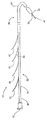
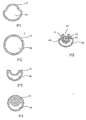
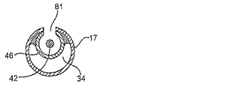
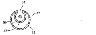
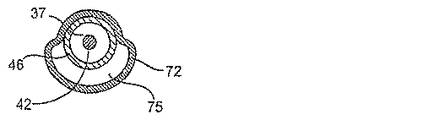
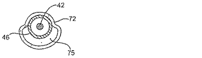
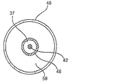
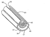
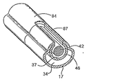
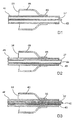
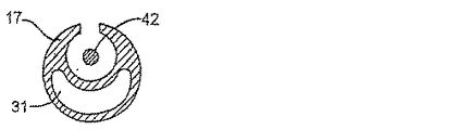
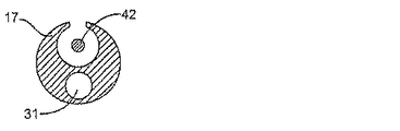
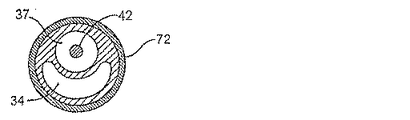
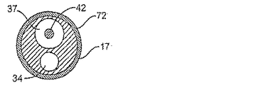
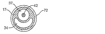
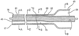
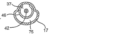
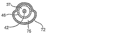
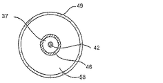
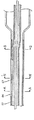
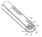
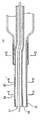
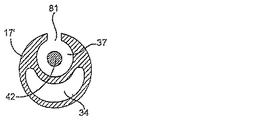
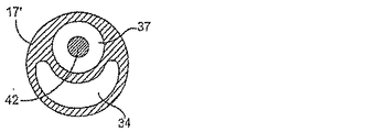
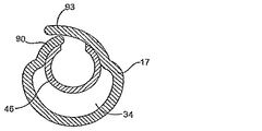
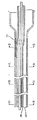
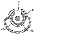
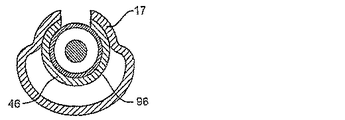
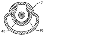
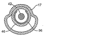
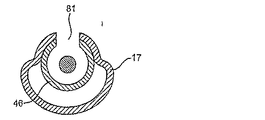
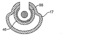
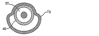
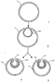
図1〜4に、本発明の特徴を具現し、カテーテルシャフトであって可撓性の管状シャフト17、近位端19、遠位先端23を有する遠位端22、近位部分25、および遠位部分28、ならびにカテーテルシャフトの少なくとも一部に沿って延びるルーメン31とを有するカテーテルシャフト16を含む血管内カテーテル13を一般的に含む、血管内カテーテルアセンブリ10の特徴を示す。膨張用ルーメン34など、カテーテルシャフト16の遠位端22に対して近位側の位置で終端する少なくとも1つのルーメンが、カテーテルシャフトの少なくとも一部に沿って延びる。図に示す態様において、カテーテルシャフトは、ガイドワイヤ42、ルーメン44を有する管状体43、または中にガイドワイヤ42を有する管状体43などの細長部品40を受容するための第二のルーメン37をさらに含む。カテーテルシャフトの近位端は、図2P1〜4の例示的態様に示すように膨張用ルーメン34のみを有していてもよく、または、図2P5に示すように膨張用ルーメンと細長部品受容ルーメン37とを有していてもよい。カテーテルシャフトの細長部品受容ルーメン37は、少なくともその一部に沿って、図3とそれに対応する横断面図に示すようにカテーテルシャフトルーメン31の中に配置された管状体46によって形成されていてもよい。あるいは、膨張用ルーメン34および細長部品受容ルーメン37は、図5に示すように、例えば押出し成形によって、一体式の二重ルーメン構造を有する可撓性の管状シャフト17によって形成されていてもよい。可撓性の管状シャフトおよび/またはそのルーメンは、単一の長手方向に伸びる構造によって形成または複数の長手方向に伸びる流体接続されたルーメンによって形成されていてもよく、このことは理解されるべきである。近位端52と遠位端55とその間にわたる膨張可能な内側58とを有し、膨張用ルーメン34と流体接触状態にある膨張可能バルーン49が、カテーテルシャフトの遠位部分28に配置される。血管内経路における追従を容易にするため、遠位先端23にはテーパがついていてもよい。遠位先端23はカテーテルシャフト17の他の部分と一体で形成されていてもよく、または、別に形成したうえで接着剤、熱融合、もしくはその他の手法により取り付けられていてもよい。いくつかの場合において、遠位先端23は、カテーテル導入の非傷害性を高めるため特に柔らかい材料で形成されていてもよい。
【0039】
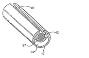
図1に示すように、本発明の血管内カテーテル13はその一部がガイドカテーテル61の中に配置される。図に示すように、カテーテルアセンブリ10は、カテーテルシャフト16の近位側末端66に取り付けられたルアー式フィッティング63を含み、カテーテルシャフト16にX線造影剤を導入するためのシリンジまたはその他の種類の器具を接続できるよう適合される。説明をわかりやすくするため、膨張、ステント送達系、もしくはその他の用途を目的として本発明の装置と共に使用できるアセンブリの構成部品は必ずしもその全てが示されているとは限らず、このことは理解されるべきである。
【0040】
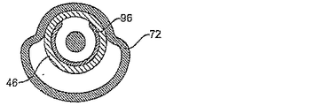
図3に示すように、1つの態様において、スリーブ72など可撓性の管状部品69は、バルーンの近位端52から遠位方向に延びて可撓性の管状シャフト17と共に液密シールを形成し、バルーンの膨張用ルーメン75によって膨張用ルーメン34とバルーンの内側58との間で流体接触をつくる。あるいは、可撓性の管状部品69は、図3S2に示すようにバルーン49と一体で形成されていてもよく、または単純にバルーンの近位シャフトの延長であってもよい。可撓性の管状シャフト17は、可撓性の管状部品69と共に延びて突合せ継手を形成していてもよい。あるいは、図3S3に示すように、可撓性の管状部品69が可撓性の管状シャフト17と共にオーバーラップ継手を形成していてもよい。
【0041】
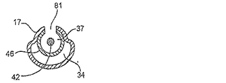
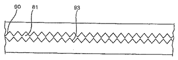
可撓性の管状シャフト17は、カテーテルシャフト16の少なくとも一部に沿って(より具体的には細長部品受容ルーメン37の少なくとも一部の中で)細長部品40を滑らせて誘導するための長手方向のアクセス81などのアクセス78を、その管状シャフトの少なくとも一部に沿って有する。
【0042】
アクセス78は、それぞれ図3および図6に示すように、可撓性の管状部品69の近位端に近接する位置まで、または可撓性の管状部品69に対して近位側の遠位位置のような、バルーン内側に対して近位側の位置もしくはその近位端まで、遠位方向に延びていてもよい。
【0043】
アクセス78は、カテーテルシャフト17の長さに沿った任意の位置まで近位方向に延びていてもよく、このような位置としては、可撓性の管状シャフト17の近位側末端;カテーテルシャフトの近位端からの距離と比較してカテーテルシャフトの遠位端から実質的に近位方向に離れた位置;カテーテルシャフトの近位端および遠位端から実質的に等距離である位置;等距離位置より遠位側であり、バルーン内側より近位側である位置;または、カテーテルシャフト近位端とバルーン内側との間にあるその他の任意の位置などがあるが、これらに限定されることはない。
【0044】
図3P1〜2および図P1〜2に、アクセス78を有する、本発明の特徴を具現するカテーテルの一部を示す。これらの図面は、アクセスを有するカテーテルの長手方向の任意の部分を示している。
【0045】
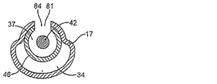
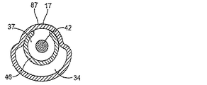
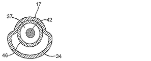
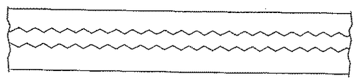
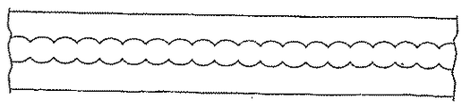
図7および図8、ならびに断面図に示すように、アクセス78は連続的であってもよく、または、アクセスでない部分87によって長手方向に区切られた複数の間欠的なアクセス部分84で構成されていてもよい。1つの態様において、アクセス78は、少なくともその近位部分の全長にわたる連続的なアクセス部分87を含み、ガイドワイヤ42、管状体43、またはガイドワイヤ42を収納する管状体かを含む細長部品を誘導するためのアクセス領域として機能する。1つの態様において、アクセス78は、その全長にわたる単一の連続的なアクセス部分87を含む。
【0046】
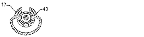
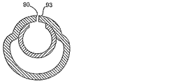
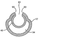
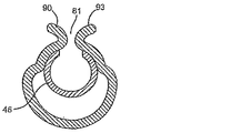
アクセス78は、例えば長手方向に伸びる横端90および93のような横端をさらに含んでいてもよい。横端同士は重複もしくは隣接していてもよく、または間隔があってもよい。図9T1〜9T3および9A1〜9A5はアクセスおよび横端を特徴とする例示的な態様である。1つの態様において、横端90および93は、細長部品40の細長部品受容ルーメン37への挿入および/または細長部品受容ルーメン37からの取り出しを可能にするだけの十分な可撓性を有する。1つの態様において、細長部品を細長部品受容ルーメンに挿入した後および/または細長部品受容ルーメンから取り出した後に横端が収縮状態に戻ることが可能になるよう、カテーテルシャフトの少なくとも横端に沿った部分は弾性を有する可撓性材料で形成される。横端同士の間に間隔がある場合、間隔は、細長部品(例えば管状部品またはガイドワイヤ)の細長部品受容ルーメンへのおよび細長部品受容ルーメンからのアクセスを可能にするだけ十分大きく、さらに細長部品が細長部品受容ルーメンから意図せず抜け出ることを最小限に抑えるだけ十分小さい。横端同士の間の間隔は互いに実質的の同じ寸法であってもよく、または、例えば遠位側に向かうにつれて増加するもしくは減少するなど、軸方向に異なっていてもよい。
【0047】
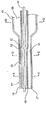
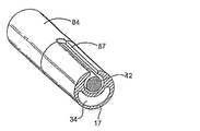
図10および対応する横断面図にその特徴を示す1つの態様において、カテーテルシャフト16は、少なくともその全長の一部にわたり、より具体的にはそのルーメンのうち少なくとも1つ(通常は細長部品受容ルーメン37)の少なくとも一部にわたる、ハイポチューブ84を含む補剛部品をさらに有していてもよい。ハイポチューブ84は、可撓性の管状部品69の近位端に向かって延びていてもよく、可撓性の管状部品69の位置またはそれに近接する位置など、バルーン内側に対して近位側の位置に向かって遠位方向に延びていてもよい。ハイポチューブ84は、カテーテルシャフト17の長さに沿った任意の位置まで近位方向に延びていてもよく、このような位置としては、可撓性の管状シャフト17の近位側末端;カテーテルシャフトの近位端からの距離と比較してカテーテルシャフトの遠位端から実質的に近位方向に離れた位置;カテーテルシャフトの近位端および遠位端から実質的に等距離である位置;等距離位置より遠位側でありバルーン内側より近位側である位置;または間にあるその他の任意の位置などがあるが、これらに限定されることはない。
【0048】
ハイポチューブ84は、細長部品受容ルーメン37の中に挿入することによって可撓性の管状シャフト17の中に配置してもよい。選択的に、ハイポチューブ84はその全長の少なくとも一部にわたってルーメン37の表面に付着させてもよい。図10M1〜10M4にその特徴を示す1つの態様においては、その全長の少なくとも一部にわたって長手方向のアクセスを有するハイポチューブ84を可撓性の管状シャフト17のルーメン31に挿入し、続いて可撓性の管状シャフト17をハイポチューブ84の外面に合わせて変形(例えば捲縮)させることによって、アクセスの横端同士の間に細長部品受容ルーメン37を形成してもよい。ハイポチューブ84は、少なくともその一部にわたって、例えば接着剤99などの適切な手段によって可撓性の管状シャフト17にさらに付着させてもよい。
【0049】
ハイポチューブは任意の適切な材料で形成してよく、そのような材料としては例えば金属および/もしくは金属合金、ポリマー、またはそれらの組合せ(ステンレス鋼、ニッケルチタン合金(例えばNitinol(商標)合金)、またはそれらの組合せなど)がある。ハイポチューブはさらにポリマー材料でコーティングまたは封入されていてもよい。その他の例としては、長手方向に組成の配分が異なる複合材料および/またはポリマーで形成されたハイポチューブがある。
【0050】
本発明のカテーテルの寸法は、治療対象とする体内部分、特に血管内において、特定の標的部位に適合するよう選択される。通常、冠動静脈の治療に使用する場合、カテーテルシャフト16の長手方向の寸法は約10 cm〜約200 cmであり、通常は約50 cm〜約200 cmであり、典型的には約125 cm〜約150 cmである。
【0051】
バルーンまたはその他の膨張可能な構造の長さは一般的にスリーブの長さより短く、通常はスリーブの長さよりはるかに短く、典型的には約4〜約60 mmであり、通常は約10〜約50 mmであり、典型的には約20〜約40 mmであり、バルーンの有効長は約5〜約40 mmである。
【0052】
膨張用ルーメン34の長さは通常、バルーン内側の膨張用ルーメンの終端点に対して遠位側のカテーテルシャフトの長さを除いたカテーテルシャフトの長さとほぼ同じであり、通常、約10 cm〜約150 cmである。
【0053】
細長部品受容ルーメン37の長さは一般的に約1 cm〜約200 cmであってよく、通常は約1 cm〜約150 cmであり、典型的には約10 cm〜約150 cmである。
【0054】
細長部品受容ルーメン37の大きさは、ガイドワイヤ42および管状部品43などの細長部品を収納するのに適した大きさである。細長部品受容ルーメン37の内径は通常、約0.0145インチ(0.368 mm)〜0.03インチ(0.762 mm)であり、好ましくは約0.016インチ(0.406 mm)〜約0.02インチ(0.512 mm)である。
【0055】
ガイドワイヤの直径は典型的に約0.006インチ(0.15 mm)または約0.008インチ(0.20 mm)〜約0.035インチ(0.89 mm)である。ガイドワイヤルーメンの直径は典型的に0.2 mm〜2 mmであり、通常は0.4 mm〜0.6 mmである。管状体43を使用する態様において、管状部品の外径および内径は、細長部品受容ルーメン37の中に配置できガイドワイヤ42を受容できるよう設定される。
【0056】
アクセス81の長手方向の寸法は、可撓性の管状シャフト17の遠位端からアクセスの遠位端までの長さを除いた、可撓性の管状シャフトの長さと実質的に等しくてもよい。1つの態様において、アクセス81の長手方向の寸法は、可撓性の管状シャフト17の近位端から、可撓性の管状シャフトの近位端および遠位端からの距離が実質的に等しい位置までの距離の分だけ、近位側でさらに短くなる。この場合、等距離位置がアクセスの近位端を規定する。または、アクセス81の長手方向の寸法は、可撓性の管状シャフト17の近位端から、可撓性の管状シャフトの近位端よりも可撓性の管状シャフトの遠位端に近い位置までの距離の分だけ、近位側でさらに短くなる。
【0057】
カテーテルシャフトの遠位端から細長部品受容ルーメン37のアクセスの最遠位側の位置までにわたる、カテーテルシャフトの部分の長さは、約3 cm〜約50 cmであってよく、通常は約4 cm〜約40 cmであり、典型的には約5 cm〜約25 cmである。
【0058】
典型的に、アクセスの横端同士の間隔は、細長部品40の細長部品受容ルーメン37へのおよび細長部品受容ルーメン37からの誘導に適するよう設定され、約0.01インチ〜約0.1インチであってよく、通常は約0.001インチ〜約0.014インチである。
【0059】
カテーテルおよび管状体は、ポリマー材料、複合材料、組紐材料、金属材料、またはそれらの組合せにより形成してもよい。典型的に、管状体はポリマー樹脂の押出しにより形成される。適した樹脂材料としては、ポリアミド(ナイロン)、ポリイミド、ポリ塩化ビニル、PEBAX、PTFEなどがある。選択的に、カテーテル本体は押し進めやすさを向上および/または壁厚を小さくするため、組紐、コイル、フィラメント、またはその他の材料で選択的に補強してもよい。
【0060】
本発明の特徴を具現した例示的な方法においては、ガイドカテーテル61を従来の方式で冠動脈に挿入する。バルーンカテーテルなど本発明の器具は、ガイドカテーテル61内に従来の方式で挿入するよう準備する。次に、ガイドワイヤ42などの細長部品40を逆装填(バックローディング)操作によりカテーテル13内に導入する。ガイドワイヤ42の近位側末端を、細長部品受容ルーメン37を通してカテーテルの遠位端にある遠位先端に逆向きに挿入する。バルーンカテーテルの遠位側末端を片手で保持し、ガイドワイヤを逆向きに進める。ガイドワイヤをカテーテルの近位端に向かって進めるのは細長部品受容ルーメンの内側であってもまたは外側であってもよいが、好ましくはこの近位端方向への前進中、ガイドワイヤは細長部品受容ルーメン内に維持される。可撓性または柔軟性のある先端を有するガイドワイヤ遠位端の少なくとも一部がカテーテルの遠位端から突出するまで、ガイドワイヤを近位方向に進める。
【0061】
次に、ガイドワイヤの可撓性先端が突出した状態で、カテーテル13の遠位端を、あらかじめ患者に留置したガイドカテーテル61内に滑り込ませる。細長部品受容ルーメン内にガイドワイヤが入った状態のカテーテル13を片手の指の間で把持し、ガイドカテーテル内を前進させる。カテーテルの大部分がガイドカテーテル内に入るまでこの手順を続ける。この遠位方向への前進中、カテーテルの細長部品受容ルーメン内にガイドワイヤが入っていることにより、カテーテルの押し進めやすさが向上する。
【0062】
1つの態様においては、カテーテルの細長部品受容ルーメン内にガイドワイヤを収納した状態のカテーテルを片手の指で安定的に保持し、開通または拡張させようとする狭窄部位をガイドワイヤの遠位端が通過しバルーン49などの治療用または診断用の部位が所望の病変部に到達するまで遠位方向に前進させる。ガイドワイヤおよびカテーテルは、少なくとも大部分は一緒に前進せしめられるため、狭窄部位にバルーン拡張カテーテルを通過させる際の押し進めやすさが大きく向上する。換言すると、狭窄部位または病変部の開口が非常に小さい場合は、これを通過させるためより大きな力をバルーンにかけることが可能である。
【0063】
あるいは望ましい場合、ガイドワイヤの近位側末端をカテーテルの細長部品受容ルーメンの外側に配置し、ガイドワイヤの近位端付近にトルカを取り付けてもよい。次に、患者の動脈に入るまでカテーテルより先にガイドワイヤを前進させる。細長部品受容ルーメン内にガイドワイヤを収納した状態のカテーテルを片手の指で安定的に保持したまま、カテーテルの遠位端の末端までガイドワイヤを前進させる。所望の動脈にガイドワイヤが入ったことは、当業者に周知のエックス線技術を用いた透視装置により観察可能である。当業者に周知のように、開通または拡張させようとする狭窄部位へとガイドワイヤの遠位端を進めることができるよう、所望の動脈内への可撓性先端の配置を容易にするため、ガイドワイヤを回転させるためのトルカを利用してもよい。ガイドワイヤが所望の位置に達したら、露出したガイドワイヤの近位側末端を片手の2本の指で静止状態に保持したまま、ただちに、バルーンなどの治療用または診断用の部分が所望の病変部に達するまでガイドワイヤ上でカテーテルを前進させる。バルーンが病変部または狭窄の通過に抵抗して術者がカテーテルの導入に困難を感じる場合は、ガイドワイヤをわずかに引き戻してもよい。次に術者はガイドワイヤの先端が血流中で揺れ動いていること(ガイドワイヤの先端が血流中で自由に動ける状態にあることを示す)を透視装置により確認してもよい。術者は次に、ガイドワイヤおよびカテーテルの両方を片手で把持し、両者が一体となって狭窄部位を通過するよう、両者を一体として前進させてもよい。
【0064】
バルーンが狭窄部位または病変部を通過した後、X線不透過性の造影剤をカテーテルの膨張用ルーメン34に導入することによって従来の方式でバルーンを膨張させてもよい。膨張が生じ、狭窄部位の開口を拡張することにより所望の手技が完了したら、術者は、カテーテルの細長部品受容ルーメン37の外に出ているガイドワイヤの近位側末端を2本の指で把持することによりカテーテルを迅速に取り出すことができる(トルカを使用している場合はこの段階の前にトルカを取り出してもよい)。
【0065】
カテーテルをガイドカテーテルから近位方向に引き出す際には、より多くのガイドワイヤの近位側末端がカテーテルの細長部品受容ルーメンから取り出される。望ましい場合、カテーテルの遠位端がガイドワイヤの近位端を通過するまで、カテーテルの残りの部分をガイドカテーテルから取り出してもよい。この際に、望ましい場合は、第二のカテーテル(例えば、第二のバルーンカテーテル、ステントなど展開可能な補綴材を運搬する第二のカテーテル)を、第二のカテーテルの細長部品受容ルーメンの遠位先端にガイドワイヤの近位端を導入することによってガイドワイヤ上に逆方向に装填してもよい。1つの態様において、第二のカテーテルは本発明の特徴を具現したカテーテルである。この場合、好ましくはガイドワイヤの全長の大部分を第二のカテーテルの細長部品受容ルーメン内に維持したまま、第二のカテーテルの細長部品受容ルーメンをガイドワイヤ上で遠位方向に前進させてもよい。
【0066】
次に、第二のカテーテルと、好ましくは第二のカテーテルの細長部品受容ルーメン内に実質的に収納されたガイドワイヤとを、上述のように所望の位置まで前進させてもよい。
【0067】
本発明の器具の特徴を具現したカテーテルはバルーン拡張カテーテルおよびステント展開カテーテル以外の種類のカテーテルであってもよく、これらの特徴は別の細長部品上で前進させることを必要としうる他のカテーテルの設計および使用に取り入れてもよいことは理解されるべきである。
【0068】
本明細書において特定の態様および方法を開示したが、本発明の精神および範囲から逸脱することなくこれらの態様および方法に種々の改変および変更を行うことが可能であり、このことは上述の開示から当業者に明らかであると思われる。したがって、上述の説明および図面は、添付の特許請求の範囲により規定される本発明の範囲を制限するものとみなされるべきではない。
【図面の簡単な説明】
【0069】
【図1】本発明の特徴を具現したバルーンカテーテルアセンブリの部分切取立面図である。
【図2】図2P1〜5は近位部分を有する、本発明の特徴を具現したカテーテルの別の態様のいくつかを示した横断面図である。
【図3】図3は、本発明の特徴を具現したバルーンカテーテルの部分切取立面図である。図3A1〜3A4は、図3のバルーンカテーテルの種々の態様を線A-Aから見た横断面図である。図3S1〜3S3は、図3のバルーンカテーテルの種々の態様を線S-Sから見た横断面図である。図3Bは、図3のバルーンカテーテルの1つの態様を線B-Bから見た横断面図である。図3P1および3P2は、図3のカテーテルの種々の態様を示した部分切取斜視図である。
【図4】図4D1〜4D3は、本発明の特徴を具現したバルーンカテーテルの近位側末端付近の遠位部分の別の態様を示した部分切取立面図である。
【図5】図5は、図3のカテーテルの別の態様を示した部分切取立面図である。図5A1および5A2は、図5のバルーンカテーテルの種々の態様を線A-Aから見た横断面図である。図5S1〜5S3は、図5のバルーンカテーテルの種々の態様を線S-Sから見た横断面図である。図5Bは、図5のバルーンカテーテルの1つの態様を線B-Bから見た横断面図である。図5P1および5P2は、図5のカテーテルの種々の態様を示した部分切取斜視図である。
【図6】図6は図3のカテーテルの別の態様を示した部分切取立面図である。図6A、6Z、6S、および6Bは、図6のバルーンカテーテルの態様をそれぞれ線A-A、Z-Z、S-S、およびB-Bから見た横断面図である。
【図7】図7は、図3のカテーテルの別の態様を示した部分切取立面図である。図7A、7N1、および7N2は、図7のバルーンカテーテルの種々の態様をそれぞれ線A-AおよびN-Nから見た横断面図である。図7Pは、図7のカテーテルの部分切取斜視図である。
【図8】図8は図3のカテーテルの別の態様を示した部分切取立面図である。図8A、8N、および8Sは、図8のバルーンカテーテルの種々の態様をそれぞれ線A-A、N-N、およびS-Sから見た横断面図である。
【図9】図9A1〜9A5は、種々のアクセス横端を有する、図3のカテーテルの別の態様を示した横断面図である。図9T1〜9T3は、図3のカテーテルの別の態様を示した部分切取上面図である。
【図10】図10は、中にハイポチューブが配置された、図3のカテーテルの別の態様を示した部分切取立面図である。図10H、図10N1〜10N3、図10A1〜10A2、および図10S1〜10S2は、図10のバルーンカテーテルの態様をそれぞれ線H-H、N-N、A-A、およびS-Sから見た横断面図である。図10M1〜10M4は、ハイポチューブを含む図10のカテーテルを作成する方法を示した横断面図である。【Technical field】
[0001]
Background of the Invention
1. Field of the invention
The present invention relates generally to medical devices and methods. More specifically, the present invention relates to a balloon catheter having a replaceable balloon structure.
[Background Art]
[0002]
2. Description of the background art
Percutaneous transluminal angioplasty has become the first-line treatment in the treatment of stenosis in the blood vessels of a patient, particularly in coronary artery and vein. In recent years, such angioplasty has been increasingly used in combination with stenting and / or radiation therapy to prevent restenosis and hyperplasia after the procedure. When performing such multiple consecutive treatments, it is common to need to "change" the catheter used for each procedure. That is, the first angioplasty is performed using an angioplasty balloon catheter. After completion of the angioplasty procedure, a second catheter carrying a stent or other vascular prosthesis must be introduced to the treatment site. Introduction of a second catheter requires first removing the angioplasty balloon catheter and then placing the second catheter at the treatment site. Optionally, the second catheter may be further replaced with a third catheter to provide radiation or other treatments to prevent hyperplasia.
[0003]
When performing such multiple consecutive treatments, many physicians prefer to keep a “guidewire” at the treatment site. A guidewire is a small diameter, highly flexible wire that can be advanced through a blood vessel to a target site, and after having advanced to the target site, introduces an angioplasty balloon catheter and other interventional catheters. It functions as a guidance route for positioning.
[0004]
Initially, angioplasty balloon catheters were designed for introduction into blood vessels in an "on-the-wire" fashion. That is, it was designed to have access throughout the length of the catheter from the distal end to the proximal end, commonly referred to as a guidewire lumen. This catheter could be loaded onto the proximal end of a guidewire already in place in the patient and advanced over the guidewire until the distal end of the catheter reached the target site. While this method is functional, it must be able to control the guidewire during the introduction of the interventional catheter, which means that the guidewire outside the patient must be longer than the catheter being introduced. Was. Any short length will prevent the surgeon from holding the guidewire during the introduction of the catheter. Although necessary for catheterization, the long length of the guidewire (optionally in the form of a removable extension) has made handling difficult during the course of treatment other than catheter manipulation.
[0005]
To overcome the difficulties associated with long guidewires, "quick exchange" or "monorail" angioplasty catheters have been developed. Over the years, many dedicated designs have been developed. Rapid exchange catheters generally have a short guidewire lumen that extends from the distal end of the catheter to an exit port located closer to the distal end than the proximal end of the catheter. By reducing the length of the guidewire lumen, the length of the guidewire protruding outside the patient can be reduced.
[0006]
Rapid exchange catheters have become widespread and have been found to be particularly useful as stented catheters. Stented catheters are commonly used after an initial angioplasty procedure. In such a case, the angioplasty catheter is removed and replaced with a stented catheter. The use of an angioplasty catheter with a rapid exchange design facilitates removal of the angioplasty catheter with a short guidewire. Similarly, the use of a quick-change design indwelling stent facilitates introduction of the catheter over a guidewire that remains in place in the patient.
[0007]
While rapid exchange catheters are widely accepted, they also have a number of limitations. In particular, the "easy pushing" of the catheter is impaired due to the short guidewire lumen.
[0008]
A second problem with the use of rapid exchange catheters is the inability to exchange or reintroduce the guidewire into a short guidewire lumen.
[0009]
For these reasons, it would be desirable to provide improved instruments, methods, and kits that allow replacement of catheters and catheter parts over short guidewires. In particular, a catheter component that has better "ease of pushing" when introduced into a blood vessel and which allows for removal of the catheter over a short guidewire and / or on a catheter body indwelled on the guidewire It would be desirable to provide improved angioplasty balloon catheters and other catheters that can be replaced. At least some of these objectives will be met by the invention as set forth in the claims hereinafter.
DISCLOSURE OF THE INVENTION
[0010]
Summary of the Invention
The present invention is directed to intracorporeal devices and methods of using them, and more specifically to intraluminal devices such as catheters, including balloon catheters. The devices of the present invention can be used for diagnostic and / or therapeutic applications. The present invention is suitable for treating various conditions at various locations on a patient's body, such as the patient's blood vessels. Specifically, the devices of the present invention can be used in virtually any treatment modality based on procedures such as, but not limited to, balloon dilatation (especially angioplasty), stenting, and the like, in the blood vessels of the patient's heart, peripheral, and brain regions. Can be used.
[0011]
As used herein, the term "intracorporeal body" means a lumen in the body, or a tissue or organ in the body. The body lumen can be any blood vessel in the patient's vasculature, including veins, arteries, aorta, and especially the coronary and peripheral arteries, or can be a previously placed graft, shunt, fistula, etc. You may. It will be appreciated that the present invention may also be used in other body lumens, such as the bile duct, where neoplastic excessive cell proliferation can occur. Examples of internal tissues and organs include various organs, nerves, glands, and ducts.
[0012]
In one embodiment, the intravascular catheter of the present invention includes a therapeutic or diagnostic structure. In one embodiment, the therapeutic or diagnostic structure is a balloon structure. Hereinafter, various features and aspects of the present invention will be further described with respect to balloon catheters, but are not intended to limit the scope of the present invention.
[0013]
In one embodiment, the device of the present invention is disposed on an elongate catheter shaft having a proximal end and a distal end, a proximal portion and a distal portion, and a distal portion of the elongate shaft, where the device is sealingly mounted. An intravascular catheter comprising a diagnostic or therapeutic structure, such as an expandable component such as an inflatable component (eg, a balloon) to be secured. At least one lumen, such as an inflation lumen, extends along at least a portion of the catheter shaft. In some embodiments, the inflation lumen terminates at a location proximal to the distal end of the catheter shaft and is in fluid contact with the inside of the balloon. The catheter shaft may be of unitary construction or may be formed of a plurality of longitudinally fluidly connectable parts.
[0014]
In one embodiment, the catheter shaft is an elongated component-receiving lumen extending along at least a portion of the shaft having a proximal end and a distal end, wherein the catheter shaft is a tubular body, a guidewire, or a guide disposed within the tubular body. It further includes an elongated component receiving lumen for slidably and removably receiving a wire or the like. In one aspect, the elongate component receiving lumen extends to a distal port at the distal end of the shaft. The proximal end of the elongate component receiving lumen may be located at a location along the length of the catheter shaft, the location being relative to the proximal end of the catheter shaft; Distal and substantially closer to the proximal end of the shaft than the distal end of the shaft; distal to the proximal end of the catheter shaft and from the proximal and distal ends of the shaft Positions at substantially equal distances; such as, but not limited to, positions distal to the proximal end of the catheter shaft and proximal to the proximal end of the balloon. The multiple lumens of the catheter shaft may be formed as a single, dual-lumen catheter body, or may be formed as separate tubular parts with lumens therein.
[0015]
The elongate component receiving lumen includes an access having a proximal end and a distal end over at least a portion of its entire length. At least a portion of the interior of the elongated component receiving lumen is fluidly connectable to the exterior of the catheter shaft by access. The access may further have a longitudinally extending transverse end. The lateral edges of the access may overlap or be adjacent, or may be spaced apart. In one embodiment, the transverse end is sufficiently flexible to allow insertion of the elongate component into and / or removal from the elongate component receiving lumen. In one embodiment, the catheter shaft at least along the transverse end is adapted to allow the transverse end to return to a contracted state after the elongate component is inserted into and / or removed from the elongate component receiving lumen. It is formed of a flexible material having elasticity. If there is a spacing between the lateral ends, the spacing is large enough to allow access of the elongated component (eg, a tubular component or a guidewire) to and from the elongated component receiving lumen, and Small enough to minimize unintentional escape of the elongated component from the elongated component lumen.
[0016]
The proximal end of the access may coincide with the proximal end of the elongated component receiving lumen, or may be located distal to the proximal end of the elongated component receiving lumen. The location distal to the proximal end of the elongate component receiving lumen is distal to the proximal end of the elongate component receiving lumen and substantially at the proximal end of the shaft than the distal end of the shaft. Near position; distal to the proximal end of the elongated component receiving lumen and substantially equal in distance from the proximal and distal ends of the shaft; distal to the proximal end of the elongated component receiving lumen. Side, which is proximal to the proximal end of the balloon, such as, but not limited to.
[0017]
The distal end of the access may be anywhere between the access proximal end and the inside of the balloon, and is usually proximate to the proximal end of the balloon.
[0018]
The access may include a single continuous access, or may include intermittent multiple accesses along the entire length of the elongated component receiving lumen. In one embodiment, the access includes a continuous access from a first end of the access to a distal end.
[0019]
Alternatively, an optional flexible tubular component, such as a sleeve, which may be formed integrally with the balloon or present as a separate component, extends proximally from the balloon along at least a portion of the distal portion of the catheter shaft. May be. In one embodiment, the sleeve is attached to the catheter shaft.
[0020]
In one embodiment, a hypotube may extend along at least a portion of the elongated component receiving lumen to further enhance the pushability of the device of the present invention.
[0021]
The dimensional characteristics of the devices falling within the scope of the present invention may vary depending on the target site in the body and the intended clinical application.
[0022]
In one aspect, the elongate component (eg, a guidewire) may be at least partially disposed within the elongate component receiving lumen during the procedure. By placing the elongate component (eg, a guidewire disposed within the lumen of the tubular component) inside the elongate component receiving lumen, the pushing strength required for improved advancement of the elongate component within the body is obtained. This also helps reduce shaft buckling.
[0023]
In one aspect, the elongate component is a tubular component having a lumen for receiving another elongate component, such as a guidewire. The cross section of the catheter may be of any suitable shape, including circular, oval, or oval.
[0024]
The distal end of one or both of the catheter shaft and the elongate component is preferably at least 3 mm, typically at least 0.5 mm, preferably at least 0.5 mm, to facilitate maneuvering through tortuous portions of the body part. It has an axial taper over a length of at least 0.1 mm. The elongate component may also have a non-injurious distal end.
[0025]
The device of the present invention may be used independently or as an assembly. Optionally, the assembly may be a mass assembly further comprising at least a second therapeutic or diagnostic instrument. By way of example, when available as an assembly, it will typically be pre-loaded with an instrument, such as a balloon catheter, over an elongate component (eg, a guidewire, tubular body, guidewire within a tubular body), and the assembly sterilized to form a complete unit. Will be packaged. A second therapeutic or diagnostic structure, such as a second balloon catheter, may have an elongate component receiving lumen receivable on the elongate component by sliding. The second balloon catheter may be included with the first balloon catheter and elongate component as part of a single assembly assembly, or as a separate package for use with the assembly or elongate component of the present invention. It may be usable.
[0026]
Typically, the second balloon catheter has dimensions such as diameter, length, or both; shape; material of the balloon; characteristics of the balloon, such as compliance, flexibility, elasticity; Different from the first balloon catheter. In one embodiment, at least one of the balloon catheters, typically the second catheter, may carry a stent or other vascular prosthesis. Usually, but not necessarily, the first balloon catheter is used to perform an angioplasty or other therapeutic or diagnostic procedure, and the second balloon catheter is used to carry the stent after the angioplasty procedure. Used for purpose. Other examples include drug infusion balloon catheters, radioactive material delivery balloon catheters, atherectomy catheters, and the like. Of course, an intravascular catheter assembly that includes only a single balloon catheter may be adapted for stent delivery, drug infusion balloons, radioactive material delivery balloons, and the like.
[0027]
In one embodiment, the intravascular catheters and / or assemblies of the present invention may further include an embolic capture component deployable on one or both of the elongated component and the balloon catheter. The deployable embolic capture component may include a coil, wire, braid, mesh, etc., and may be of various shapes, such as a funnel or parachute. Preferably, the embolic capture component is formed from a material such as a nickel titanium alloy (such as a Nitinol ™ alloy), spring stainless steel, and may be coated or encapsulated with a polymeric material. The deployable embolic capture component filters and / or aspirates any emboli (which may occlude body lumens) before, during, and / or after treatment with the intravascular catheter. It becomes possible. Embolic filters generally have microscopic holes for collecting emboli, from about 1 micron (μm) to about 200 μm, usually from about 1 μm to about 100 microns. The embolic filter may be at least partially opened and closed by axial or radial movement of the balloon structure or catheter body.
[0028]
In another aspect, the intravascular catheter and / or assembly of the present invention further comprises a second inflatable balloon on the elongate component configured to be distal to the first balloon catheter. Is also good. The dimensions, properties, and materials of formation of the second balloon may be similar to the first balloon described above. The second balloon may also carry a vascular prosthesis that can be deployed by the balloon. In some cases, an angioplasty or other therapeutic or diagnostic procedure is performed with a first balloon and a stent (a balloon-deployable stent) is delivered using a second balloon after the angioplasty procedure. You may. Therefore, such an embodiment is suitable for performing continuous treatment with a single catheter structure.
[0029]
In another aspect, the intravascular catheter of the present invention may have a self-expanding vascular prosthesis on the elongated component. Self-expanding vascular prostheses may be formed from steel, nickel titanium, shape memory alloys, cobalt, composites, and the like. Typically, the self-expanding vascular prosthesis is at least partially deployed by axial or radial movement of the first balloon catheter and / or the elongate component.
[0030]
In one exemplary method embodying features of the present invention, a guide catheter is inserted into a coronary artery in a conventional manner. The device of the present invention, such as a balloon catheter, is prepared for insertion into a guide catheter in a conventional manner. Next, an elongated component such as a guidewire is introduced into the catheter by a back loading operation. The proximal end of the guidewire is inserted back through the elongate component receiving lumen into the distal tip at the distal end of the catheter. Advance the guidewire by holding the distal end of the balloon catheter with one hand and advancing the guidewire in the opposite direction. The guidewire may be advanced toward the proximal end of the catheter either inside or outside the elongate part receiving lumen. Preferably, however, during advancement in the proximal direction, the guidewire is maintained within the elongated component receiving lumen. Advance the guidewire proximally until at least a portion of the guidewire distal end having a flexible or flexible tip protrudes from the distal end of the catheter.
[0031]
The distal end of the catheter is then slid into a guide catheter previously indwelled in the patient with the flexible tip of the guidewire protruding. The catheter with the guidewire in the elongated component receiving lumen is grasped between the fingers of one hand and advanced through the guide catheter. Continue this procedure until most of the catheter is inside the guide catheter. During this distal advancement, the guidewire within the elongate part receiving lumen of the catheter enhances the ease of pushing the catheter.
[0032]
In one embodiment, the distal end of the guidewire is used to stably hold the catheter with the guidewire housed in the elongate part receiving lumen of the catheter with one finger and to open or expand the stenosis site. It is advanced distally until it passes and a therapeutic or diagnostic site, such as a balloon, reaches the desired lesion. Since the guidewire and the catheter are at least mostly advanced together, the pushability when the balloon dilatation catheter is advanced to the stenosis site is greatly improved. In other words, if the opening at the stenosis or lesion is very small, it is possible to apply a greater force to the balloon to pass through it.
[0033]
Alternatively, if desired, the proximal end of the guidewire may be located outside the elongate component receiving lumen of the catheter, and a torquer may be attached to the guidewire near the proximal end of the guidewire. The guidewire is then advanced ahead of the catheter until it enters the patient's artery. The guidewire is advanced to a position distal to the distal end of the catheter while the catheter with the guidewire housed in the elongated component receiving lumen is stably held with one finger. The placement of the guidewire in the desired artery can be observed with a fluoroscope using x-ray techniques well known to those skilled in the art. As is well known to those skilled in the art, to facilitate placement of the flexible tip within the desired artery so that the distal end of the guidewire can be advanced into the stenosis site to be opened or dilated. A torquer for rotating the guide wire may be used. Once the guidewire has reached the desired position, immediately hold the exposed distal end of the guidewire stationary with the two fingers of one hand and place the therapeutic or diagnostic portion, such as a balloon, on the desired lesion. Advance the catheter over the guidewire until it reaches the site. If the balloon is difficult to introduce the catheter as the balloon resists passage through the lesion or stenosis, the guidewire may be withdrawn slightly. Next, the operator may use a fluoroscope to confirm that the distal end of the guidewire is swinging in the bloodstream (indicating that the distal end of the guidewire is freely movable in the bloodstream). The surgeon may then grasp both the guidewire and the catheter with one hand and advance both together as a unit so that they pass through the stenosis.
[0034]
After the balloon has passed through the stenosis or lesion, the balloon may be inflated in a conventional manner by introducing a radiopaque contrast agent through the inflation lumen of the catheter. Once the dilation has occurred and the desired procedure has been completed by dilating the opening in the stenosis, the surgeon grasps the proximal end of the guidewire with two fingers outside the elongated component receiving lumen of the catheter. By doing so, the catheter can be quickly removed (if the ToruCa is used, the ToruCa may be removed before this step).
[0035]
As the catheter is withdrawn proximally from the guide catheter, more of the proximal end of the guidewire is withdrawn from the elongate part receiving lumen of the catheter. If desired, the remaining portion of the catheter may be removed from the guide catheter until the distal end of the catheter has passed the proximal end of the guidewire. At this time, if desired, a second catheter (e.g., a second balloon catheter, a second catheter carrying a deployable prosthesis such as a stent) can be placed at the distal tip of the elongated catheter receiving lumen of the second catheter. The guidewire may be loaded in the opposite direction by introducing the proximal end of the guidewire into the guidewire. In one embodiment, the second catheter is a catheter embodying features of the present invention. In this case, the elongate part receiving lumen of the second catheter may be advanced distally over the guide wire, preferably while the majority of the entire length of the guidewire is maintained within the elongate part receiving lumen of the second catheter. Good.
[0036]
Next, the second catheter and, preferably, the guidewire substantially housed within the elongate part receiving lumen of the second catheter may be advanced to the desired position as described above.
[0037]
Catheters embodying the features of the device of the present invention may be of a type other than balloon dilatation catheters and stent deployment catheters, and features of the present invention may require advancement over another elongated component. May be incorporated into the design and use of the catheter. This should be understood.
[0038]
Detailed description of the invention
Referring to FIGS. 1-4, a catheter shaft embodying features of the present invention is a flexible
[0039]
As shown in FIG. 1, a part of the intravascular catheter 13 of the present invention is disposed in a
[0040]
As shown in FIG. 3, in one embodiment, a flexible
[0041]
The flexible
[0042]
The
[0043]
[0044]
3P1-2 and FIGS. P1-2 illustrate a portion of a
[0045]
As shown in FIGS. 7 and 8, and in cross-section, the
[0046]
[0047]
In one embodiment, the features of which are shown in FIG. 10 and corresponding cross-sectional views, the
[0048]
The
[0049]
The hypotube may be formed of any suitable material, such as, for example, metals and / or metal alloys, polymers, or combinations thereof (stainless steel, nickel titanium alloys (eg, Nitinol ™ alloy), Or combinations thereof). The hypotube may be further coated or encapsulated with a polymeric material. Another example is a hypotube formed of a composite material and / or polymer with a different composition distribution in the longitudinal direction.
[0050]
The dimensions of the catheter of the present invention are selected to fit a particular target site within the body part to be treated, particularly within a blood vessel. Typically, when used for the treatment of coronary artery and vein, the longitudinal dimension of the
[0051]
The length of the balloon or other inflatable structure is generally less than the length of the sleeve, usually much less than the length of the sleeve, typically about 4 to about 60 mm, usually about 10 to about 60 mm. The diameter is 50 mm, typically about 20 to about 40 mm, and the effective length of the balloon is about 5 to about 40 mm.
[0052]
The length of the
[0053]
The length of the elongate
[0054]
The size of the elongated
[0055]
The diameter of the guidewire is typically about 0.006 inches (0.15 mm) or about 0.008 inches (0.20 mm) to about 0.035 inches (0.89 mm). The diameter of the guidewire lumen is typically between 0.2 mm and 2 mm, usually between 0.4 mm and 0.6 mm. In an embodiment using a
[0056]
The longitudinal dimension of the
[0057]
The length of the portion of the catheter shaft, ranging from the distal end of the catheter shaft to the distal-most point of access of the elongate
[0058]
Typically, the spacing between the lateral ends of the access is set to be suitable for guiding the
[0059]
The catheter and tubular body may be formed from a polymeric material, a composite material, a braided material, a metallic material, or a combination thereof. Typically, the tubular body is formed by extrusion of a polymer resin. Suitable resin materials include polyamide (nylon), polyimide, polyvinyl chloride, PEBAX, PTFE, and the like. Optionally, the catheter body may be selectively reinforced with braids, coils, filaments, or other materials to improve pushability and / or reduce wall thickness.
[0060]
In an exemplary method embodying features of the present invention, a
[0061]
Next, with the flexible tip of the guide wire protruding, the distal end of the catheter 13 is slid into the
[0062]
In one embodiment, the distal end of the guidewire is used to stably hold the catheter with the guidewire stored in the elongate part receiving lumen of the catheter with one finger and to open or expand the stenosis site. It is advanced distally until it passes and a therapeutic or diagnostic site, such as
[0063]
Alternatively, if desired, the proximal end of the guidewire may be located outside the elongate component receiving lumen of the catheter, and a torquer may be mounted near the proximal end of the guidewire. The guidewire is then advanced ahead of the catheter until it enters the patient's artery. The guidewire is advanced to the distal end of the catheter while the catheter with the guidewire stored in the elongated component receiving lumen is stably held with one finger. The insertion of the guidewire into the desired artery can be observed with a fluoroscope using x-ray techniques well known to those skilled in the art. As is well known to those skilled in the art, to facilitate placement of the flexible tip within the desired artery so that the distal end of the guidewire can be advanced to the site of the stenosis to be opened or dilated. A torquer for rotating the guide wire may be used. Once the guidewire has reached the desired position, immediately hold the exposed distal end of the guidewire stationary with the two fingers of one hand and place the therapeutic or diagnostic portion, such as a balloon, on the desired lesion. Advance the catheter over the guidewire until it reaches the site. If the balloon is difficult to introduce the catheter as the balloon resists passage through the lesion or stenosis, the guidewire may be withdrawn slightly. Next, the operator may use a fluoroscope to confirm that the distal end of the guidewire is swinging in the bloodstream (indicating that the distal end of the guidewire is freely movable in the bloodstream). The surgeon may then grasp both the guidewire and the catheter with one hand and advance both together as a unit so that they pass through the stenosis.
[0064]
After the balloon has passed the stenosis or lesion, the balloon may be inflated in a conventional manner by introducing a radiopaque contrast agent into the
[0065]
As the catheter is withdrawn proximally from the guide catheter, more of the proximal end of the guidewire is withdrawn from the elongate part receiving lumen of the catheter. If desired, the remaining portion of the catheter may be removed from the guide catheter until the distal end of the catheter has passed the proximal end of the guidewire. At this time, if desired, a second catheter (e.g., a second balloon catheter, a second catheter carrying a deployable prosthesis such as a stent) can be placed distally of the elongate component receiving lumen of the second catheter. The guidewire may be loaded in the opposite direction by introducing the proximal end of the guidewire to the tip. In one embodiment, the second catheter is a catheter embodying features of the present invention. In this case, the elongate part receiving lumen of the second catheter may be advanced distally over the guide wire, preferably while the majority of the entire length of the guidewire is maintained within the elongate part receiving lumen of the second catheter. Good.
[0066]
Next, the second catheter and, preferably, the guidewire substantially housed within the elongate part receiving lumen of the second catheter may be advanced to the desired position as described above.
[0067]
Catheters embodying the features of the device of the present invention may be other types of catheters than balloon dilatation catheters and stent deployment catheters, and these features may be necessary for other catheters that may need to be advanced over another elongated component. It should be understood that it may be incorporated into design and use.
[0068]
Although particular embodiments and methods have been disclosed herein, various modifications and changes may be made to these embodiments and methods without departing from the spirit and scope of the invention, which is to be understood by the above disclosure. Would be apparent to those skilled in the art. Therefore, the above description and illustrations should not be taken as limiting the scope of the invention, which is defined by the appended claims.
[Brief description of the drawings]
[0069]
FIG. 1 is a partial cutaway elevation view of a balloon catheter assembly embodying features of the present invention.
2P1-5 are cross-sectional views illustrating some of the other embodiments of a catheter embodying features of the invention having a proximal portion.
FIG. 3 is a partially cutaway elevation view of a balloon catheter embodying features of the present invention. 3A1 to 3A4 are cross-sectional views of various aspects of the balloon catheter of FIG. 3S1 to 3S3 are cross-sectional views of various aspects of the balloon catheter of FIG. 3 as viewed from line SS. FIG. 3B is a cross-sectional view of one embodiment of the balloon catheter of FIG. 3 as viewed from line BB. 3P1 and 3P2 are partially cutaway perspective views illustrating various aspects of the catheter of FIG.
FIGS. 4D1-4D3 are partial cutaway elevation views illustrating another embodiment of a distal portion near a proximal end of a balloon catheter embodying features of the present invention.
FIG. 5 is a partially cut away elevation view showing another embodiment of the catheter of FIG. 3; 5A1 and 5A2 are cross-sectional views of various embodiments of the balloon catheter of FIG. 5, as viewed from line AA. 5S1-5S3 are cross-sectional views of various aspects of the balloon catheter of FIG. 5 as viewed from line SS. FIG. 5B is a cross-sectional view of one embodiment of the balloon catheter of FIG. 5, taken along line BB. 5P1 and 5P2 are partially cutaway perspective views showing various embodiments of the catheter of FIG.
FIG. 6 is a partially cutaway elevational view showing another embodiment of the catheter of FIG. 3; 6A, 6Z, 6S, and 6B are cross-sectional views of the embodiment of the balloon catheter of FIG. 6 as seen from lines AA, ZZ, SS, and BB, respectively.
FIG. 7 is a partially cutaway elevational view showing another embodiment of the catheter of FIG. 3; 7A, 7N1, and 7N2 are cross-sectional views of various embodiments of the balloon catheter of FIG. 7 taken along lines AA and NN, respectively. FIG. 7P is a partially cutaway perspective view of the catheter of FIG.
FIG. 8 is a partially cutaway elevational view showing another embodiment of the catheter of FIG. FIGS. 8A, 8N, and 8S are cross-sectional views of various embodiments of the balloon catheter of FIG. 8 taken along lines AA, NN, and SS, respectively.
9A1-9A5 are cross-sectional views illustrating another embodiment of the catheter of FIG. 3 having various access lateral ends. 9T1-9T3 are partially cutaway top views showing another embodiment of the catheter of FIG.
FIG. 10 is a partially cut away elevation view of another embodiment of the catheter of FIG. 3, with the hypotube disposed therein. 10H, 10N1 to 10N3, 10A1 to 10A2, and 10S1 to 10S2 are cross-sectional views of the embodiment of the balloon catheter of FIG. 10 as seen from lines HH, NN, AA, and SS, respectively. 10M1 to 10M4 are cross-sectional views illustrating a method of making the catheter of FIG. 10 including a hypotube.
Claims (42)
近位端、および遠位ポートを有する遠位端;
近位端を含む近位部分、および遠位端を含む遠位部分;
近位端および遠位端を有し、中に細長部品を受容するため近位部分と遠位部分との間にわたって延びる細長部品受容ルーメン;ならびに
細長部品を、細長部品受容ルーメンへまたは細長部品受容ルーメンから誘導するためのアクセス。Intravascular catheter comprising an elongated catheter shaft having:
A proximal end, and a distal end having a distal port;
A proximal portion including a proximal end, and a distal portion including a distal end;
An elongated component receiving lumen having a proximal end and a distal end and extending between the proximal and distal portions to receive the elongated component therein; and the elongated component to or into the elongated component receiving lumen. Access to guide from lumens.
近位端、および遠位ポートを有する遠位端;
近位端を含む近位部分、および遠位端を含む遠位部分;
近位端および遠位端を有し、中に細長部品を受容するため近位部分と遠位部分との間にわたって延びる細長部品受容ルーメン;ならびに
細長部品を、細長部品受容ルーメンへまたは細長部品受容ルーメンから誘導するためのアクセス。An intravascular catheter for performing a procedure at a location within a patient's coronary artery, the catheter having a proximal end and a distal end and an internal lumen extending therethrough, wherein a distal end of a guide catheter is located at the patient's coronary ostium. An intravascular catheter configured for use with a guide catheter positioned at a proximal end of the guide catheter and extending out of the patient's body, the catheter comprising an elongated catheter shaft having:
A proximal end, and a distal end having a distal port;
A proximal portion including a proximal end, and a distal portion including a distal end;
An elongated component receiving lumen having a proximal end and a distal end and extending between the proximal and distal portions to receive the elongated component therein; and the elongated component to or into the elongated component receiving lumen. Access to guide from lumens.
近位端、および遠位ポートを有する遠位端;
近位端を含む近位部分、および遠位端を含む遠位部分;
近位端および遠位端を有し、中に細長部品を受容するため近位部分と遠位部分との間にわたって延びる細長部品受容ルーメン;ならびに
細長部品を、細長部品受容ルーメンへまたは細長部品受容ルーメンから誘導するためのアクセスであって、カテーテルシャフトの遠位端から近位側に約3〜約50 cm離れた位置に配置されたアクセス。Intravascular catheter comprising an elongated catheter shaft having:
A proximal end, and a distal end having a distal port;
A proximal portion including a proximal end, and a distal portion including a distal end;
An elongated component receiving lumen having a proximal end and a distal end and extending between the proximal and distal portions to receive the elongated component therein; and the elongated component to or into the elongated component receiving lumen. An access for guiding from a lumen, wherein the access is located about 3 to about 50 cm proximal to a distal end of the catheter shaft.
近位端、および中に遠位ポートを有する遠位端;
近位端を含む近位部分、および遠位端を含む遠位部分;
近位端および遠位端を有し、中に細長部品を受容するため近位端と遠位端との間にわたって延びる細長部品受容ルーメン;ならびに
細長部品を、細長部品受容ルーメンへまたは細長部品受容ルーメンから誘導するためのアクセスであって、細長部品受容ルーメンの近位端から細長部品受容ルーメンの遠位端に近接した位置まで延びるアクセス。Intravascular catheter comprising an elongated catheter shaft having:
A proximal end, and a distal end having a distal port therein;
A proximal portion including a proximal end, and a distal portion including a distal end;
An elongated component receiving lumen having a proximal end and a distal end, and extending between the proximal end and the distal end for receiving the elongated component therein; and the elongated component to or into the elongated component receiving lumen. An access for navigating from a lumen, the access extending from a proximal end of the elongated component receiving lumen to a position proximate a distal end of the elongated component receiving lumen.
近位端、およびそこに遠位ポートを有する遠位端;
近位端を含む近位部分、および遠位端を含む遠位部分;
近位端および遠位端を有し、中に細長部品を受容するため近位部分と遠位部分との間にわたって延びる細長部品受容ルーメン;ならびに
細長部品を、細長部品受容ルーメンへまたは細長部品受容ルーメンからカテーテルの遠位ポートへと誘導するためのアクセス。An intravascular balloon catheter for performing a procedure at a location within a patient's coronary artery, the catheter having a proximal end and a distal end and an internal lumen extending therethrough, wherein a distal end of a guide catheter is located in the patient's coronary artery. An intravascular balloon catheter configured for use with a guide catheter positioned in the mouth and designed with the proximal end of the guide catheter extending outside the patient, including an elongated catheter shaft having the following:
A proximal end, and a distal end having a distal port therein;
A proximal portion including a proximal end, and a distal portion including a distal end;
An elongated component receiving lumen having a proximal end and a distal end and extending between the proximal and distal portions to receive the elongated component therein; and the elongated component to or into the elongated component receiving lumen. Access to navigate from the lumen to the distal port of the catheter.
Applications Claiming Priority (5)
| Application Number | Priority Date | Filing Date | Title |
|---|---|---|---|
| US09/872,640 US7131986B2 (en) | 2000-06-02 | 2001-05-31 | Catheter having exchangeable balloon |
| US121001A | 2001-11-30 | 2001-11-30 | |
| US10/080,920 US7238168B2 (en) | 2000-06-02 | 2002-02-20 | Exchangeable catheter |
| US36607902P | 2002-03-18 | 2002-03-18 | |
| PCT/US2002/017164 WO2002096483A2 (en) | 2001-05-31 | 2002-05-31 | Exchangeable catheter |
Publications (2)
| Publication Number | Publication Date |
|---|---|
| JP2004528126A true JP2004528126A (en) | 2004-09-16 |
| JP2004528126A5 JP2004528126A5 (en) | 2005-12-22 |
Family
ID=27485070
Family Applications (1)
| Application Number | Title | Priority Date | Filing Date |
|---|---|---|---|
| JP2002592991A Pending JP2004528126A (en) | 2001-05-31 | 2002-05-31 | Replaceable catheter |
Country Status (3)
| Country | Link |
|---|---|
| EP (1) | EP1390095A4 (en) |
| JP (1) | JP2004528126A (en) |
| WO (1) | WO2002096483A2 (en) |
Cited By (7)
| Publication number | Priority date | Publication date | Assignee | Title |
|---|---|---|---|---|
| JP2008536586A (en) * | 2005-04-18 | 2008-09-11 | トライレム メディカル, インコーポレイテッド | Apparatus and method for delivering a prosthesis to a bifurcation of a tubular structure |
| JP2013184020A (en) * | 2012-03-12 | 2013-09-19 | Goodman Co Ltd | Catheter |
| WO2014013565A1 (en) * | 2012-07-18 | 2014-01-23 | テルモ株式会社 | Medical treatment instrument |
| JP2015066394A (en) * | 2013-10-01 | 2015-04-13 | 住友ベークライト株式会社 | Gastrostoma assist tube and assist kit for exchanging gastrostomy catheter |
| JP2017153698A (en) * | 2016-03-01 | 2017-09-07 | オリンパス株式会社 | Endoscopic treatment device |
| JP2018529486A (en) * | 2015-08-11 | 2018-10-11 | ペーテーテー ホールディング アーペーエスPtt Holding Aps | Delivery device |
| JP2020048606A (en) * | 2018-09-21 | 2020-04-02 | テルモ株式会社 | Catheter and treatment method using the same |
Families Citing this family (3)
| Publication number | Priority date | Publication date | Assignee | Title |
|---|---|---|---|---|
| US7766868B2 (en) | 2003-09-05 | 2010-08-03 | Medtronic, Inc. | Deflectable medical therapy delivery device having common lumen profile |
| US9289576B2 (en) * | 2004-06-17 | 2016-03-22 | W. L. Gore & Associates, Inc. | Catheter assembly |
| JP5639896B2 (en) | 2008-01-14 | 2014-12-10 | ボストン サイエンティフィック サイムド,インコーポレイテッドBoston Scientific Scimed,Inc. | Medical equipment |
Family Cites Families (10)
| Publication number | Priority date | Publication date | Assignee | Title |
|---|---|---|---|---|
| EP0380873B1 (en) * | 1989-01-30 | 1994-05-04 | C.R. Bard, Inc. | Rapidly exchangeable coronary catheter |
| US5395335A (en) * | 1991-05-24 | 1995-03-07 | Jang; G. David | Universal mode vascular catheter system |
| US6821287B1 (en) * | 1991-05-24 | 2004-11-23 | Advanced Cardiovascular Systems, Inc. | Multi-mode vascular catheter system |
| US5154725A (en) * | 1991-06-07 | 1992-10-13 | Advanced Cardiovascular Systems, Inc. | Easily exchangeable catheter system |
| WO1995002430A1 (en) * | 1993-07-15 | 1995-01-26 | Advanced Cardiovascular Systems, Inc. | Rapid exchange type intraluminal catheter with guiding element |
| US5458605A (en) * | 1994-04-04 | 1995-10-17 | Advanced Cardiovascular Systems, Inc. | Coiled reinforced retractable sleeve for stent delivery catheter |
| US6346093B1 (en) * | 1996-09-13 | 2002-02-12 | Scimed Life Systems, Inc. | Single operator exchange biliary catheter with common distal lumen |
| US5921971A (en) | 1996-09-13 | 1999-07-13 | Boston Scientific Corporation | Single operator exchange biliary catheter |
| US6196995B1 (en) * | 1998-09-30 | 2001-03-06 | Medtronic Ave, Inc. | Reinforced edge exchange catheter |
| IE20000744A1 (en) | 1999-09-15 | 2001-05-30 | Moynesign Ltd | "A balloon catheter" |
-
2002
- 2002-05-31 WO PCT/US2002/017164 patent/WO2002096483A2/en active Application Filing
- 2002-05-31 JP JP2002592991A patent/JP2004528126A/en active Pending
- 2002-05-31 EP EP02744201A patent/EP1390095A4/en not_active Withdrawn
Cited By (9)
| Publication number | Priority date | Publication date | Assignee | Title |
|---|---|---|---|---|
| JP2008536586A (en) * | 2005-04-18 | 2008-09-11 | トライレム メディカル, インコーポレイテッド | Apparatus and method for delivering a prosthesis to a bifurcation of a tubular structure |
| JP2013184020A (en) * | 2012-03-12 | 2013-09-19 | Goodman Co Ltd | Catheter |
| WO2014013565A1 (en) * | 2012-07-18 | 2014-01-23 | テルモ株式会社 | Medical treatment instrument |
| US8936612B2 (en) | 2012-07-18 | 2015-01-20 | Terumo Kabushiki Kaisha | Medical treatment tool |
| JP2015066394A (en) * | 2013-10-01 | 2015-04-13 | 住友ベークライト株式会社 | Gastrostoma assist tube and assist kit for exchanging gastrostomy catheter |
| JP2018529486A (en) * | 2015-08-11 | 2018-10-11 | ペーテーテー ホールディング アーペーエスPtt Holding Aps | Delivery device |
| JP2017153698A (en) * | 2016-03-01 | 2017-09-07 | オリンパス株式会社 | Endoscopic treatment device |
| JP2020048606A (en) * | 2018-09-21 | 2020-04-02 | テルモ株式会社 | Catheter and treatment method using the same |
| JP7256621B2 (en) | 2018-09-21 | 2023-04-12 | テルモ株式会社 | catheter set |
Also Published As
| Publication number | Publication date |
|---|---|
| EP1390095A4 (en) | 2007-05-30 |
| EP1390095A2 (en) | 2004-02-25 |
| WO2002096483A2 (en) | 2002-12-05 |
| WO2002096483A3 (en) | 2003-03-06 |
Similar Documents
| Publication | Publication Date | Title |
|---|---|---|
| US20030055377A1 (en) | Exchangeable catheter | |
| JP6839693B2 (en) | Guide wire fixing | |
| US7238168B2 (en) | Exchangeable catheter | |
| US7131986B2 (en) | Catheter having exchangeable balloon | |
| US5980533A (en) | Stent delivery system | |
| US9220873B2 (en) | Double ended intravascular medical device | |
| US7226473B2 (en) | Treatment of stenotic regions | |
| US5413559A (en) | Rapid exchange type over-the-wire catheter | |
| US20200179661A1 (en) | Intravascular delivery system and method for percutaneous coronary intervention | |
| KR20140114825A (en) | Carotid sheath with entry and tracking rapid exchange dilators and method of use | |
| US20100298922A1 (en) | Angioplasty Assembly | |
| JPH06197972A (en) | Rapidly exchangeable catheter system | |
| US20070123926A1 (en) | Pre-curved guiding catheter with mechanically actuated occluder for embolic protection | |
| EP2015826B1 (en) | Guidewire placement device | |
| EP2227188B1 (en) | Stent placement system | |
| US7695491B2 (en) | Rapid exchange catheters with tandem lumens | |
| JP2004528126A (en) | Replaceable catheter | |
| US20100318169A1 (en) | Delivery system for endoluminal devices | |
| IES85716Y1 (en) | An angioplasty assembly | |
| IE86053B1 (en) | An angioplasty assembly | |
| IE20100331U1 (en) | An angioplasty assembly |
Legal Events
| Date | Code | Title | Description |
|---|---|---|---|
| A521 | Written amendment |
Free format text: JAPANESE INTERMEDIATE CODE: A523 Effective date: 20040805 |
|
| A621 | Written request for application examination |
Free format text: JAPANESE INTERMEDIATE CODE: A621 Effective date: 20050524 |
|
| A131 | Notification of reasons for refusal |
Free format text: JAPANESE INTERMEDIATE CODE: A131 Effective date: 20080618 |
|
| RD04 | Notification of resignation of power of attorney |
Free format text: JAPANESE INTERMEDIATE CODE: A7424 Effective date: 20080819 |
|
| A521 | Written amendment |
Free format text: JAPANESE INTERMEDIATE CODE: A523 Effective date: 20080905 |
|
| RD02 | Notification of acceptance of power of attorney |
Free format text: JAPANESE INTERMEDIATE CODE: A7422 Effective date: 20081009 |
|
| A521 | Written amendment |
Free format text: JAPANESE INTERMEDIATE CODE: A821 Effective date: 20081020 |
|
| RD04 | Notification of resignation of power of attorney |
Free format text: JAPANESE INTERMEDIATE CODE: A7424 Effective date: 20081020 |
|
| A02 | Decision of refusal |
Free format text: JAPANESE INTERMEDIATE CODE: A02 Effective date: 20081209 |