JP2004527162A - System and method for creating a user profile - Google Patents
System and method for creating a user profile Download PDFInfo
- Publication number
- JP2004527162A JP2004527162A JP2002568624A JP2002568624A JP2004527162A JP 2004527162 A JP2004527162 A JP 2004527162A JP 2002568624 A JP2002568624 A JP 2002568624A JP 2002568624 A JP2002568624 A JP 2002568624A JP 2004527162 A JP2004527162 A JP 2004527162A
- Authority
- JP
- Japan
- Prior art keywords
- user profile
- data
- stored
- user
- new user
- Prior art date
- Legal status (The legal status is an assumption and is not a legal conclusion. Google has not performed a legal analysis and makes no representation as to the accuracy of the status listed.)
- Pending
Links
Images


Classifications
-
- H—ELECTRICITY
- H04—ELECTRIC COMMUNICATION TECHNIQUE
- H04N—PICTORIAL COMMUNICATION, e.g. TELEVISION
- H04N21/00—Selective content distribution, e.g. interactive television or video on demand [VOD]
- H04N21/40—Client devices specifically adapted for the reception of or interaction with content, e.g. set-top-box [STB]; Operations thereof
- H04N21/47—End-user applications
- H04N21/475—End-user interface for inputting end-user data, e.g. personal identification number [PIN], preference data
-
- H—ELECTRICITY
- H04—ELECTRIC COMMUNICATION TECHNIQUE
- H04N—PICTORIAL COMMUNICATION, e.g. TELEVISION
- H04N21/00—Selective content distribution, e.g. interactive television or video on demand [VOD]
- H04N21/40—Client devices specifically adapted for the reception of or interaction with content, e.g. set-top-box [STB]; Operations thereof
- H04N21/43—Processing of content or additional data, e.g. demultiplexing additional data from a digital video stream; Elementary client operations, e.g. monitoring of home network or synchronising decoder's clock; Client middleware
- H04N21/433—Content storage operation, e.g. storage operation in response to a pause request, caching operations
-
- H—ELECTRICITY
- H04—ELECTRIC COMMUNICATION TECHNIQUE
- H04N—PICTORIAL COMMUNICATION, e.g. TELEVISION
- H04N21/00—Selective content distribution, e.g. interactive television or video on demand [VOD]
- H04N21/40—Client devices specifically adapted for the reception of or interaction with content, e.g. set-top-box [STB]; Operations thereof
- H04N21/45—Management operations performed by the client for facilitating the reception of or the interaction with the content or administrating data related to the end-user or to the client device itself, e.g. learning user preferences for recommending movies, resolving scheduling conflicts
- H04N21/4508—Management of client data or end-user data
- H04N21/4532—Management of client data or end-user data involving end-user characteristics, e.g. viewer profile, preferences
-
- H—ELECTRICITY
- H04—ELECTRIC COMMUNICATION TECHNIQUE
- H04N—PICTORIAL COMMUNICATION, e.g. TELEVISION
- H04N21/00—Selective content distribution, e.g. interactive television or video on demand [VOD]
- H04N21/40—Client devices specifically adapted for the reception of or interaction with content, e.g. set-top-box [STB]; Operations thereof
- H04N21/45—Management operations performed by the client for facilitating the reception of or the interaction with the content or administrating data related to the end-user or to the client device itself, e.g. learning user preferences for recommending movies, resolving scheduling conflicts
- H04N21/454—Content or additional data filtering, e.g. blocking advertisements
-
- H—ELECTRICITY
- H04—ELECTRIC COMMUNICATION TECHNIQUE
- H04N—PICTORIAL COMMUNICATION, e.g. TELEVISION
- H04N21/00—Selective content distribution, e.g. interactive television or video on demand [VOD]
- H04N21/40—Client devices specifically adapted for the reception of or interaction with content, e.g. set-top-box [STB]; Operations thereof
- H04N21/47—End-user applications
- H04N21/475—End-user interface for inputting end-user data, e.g. personal identification number [PIN], preference data
- H04N21/4751—End-user interface for inputting end-user data, e.g. personal identification number [PIN], preference data for defining user accounts, e.g. accounts for children
-
- H—ELECTRICITY
- H04—ELECTRIC COMMUNICATION TECHNIQUE
- H04N—PICTORIAL COMMUNICATION, e.g. TELEVISION
- H04N21/00—Selective content distribution, e.g. interactive television or video on demand [VOD]
- H04N21/40—Client devices specifically adapted for the reception of or interaction with content, e.g. set-top-box [STB]; Operations thereof
- H04N21/47—End-user applications
- H04N21/475—End-user interface for inputting end-user data, e.g. personal identification number [PIN], preference data
- H04N21/4755—End-user interface for inputting end-user data, e.g. personal identification number [PIN], preference data for defining user preferences, e.g. favourite actors or genre
-
- H—ELECTRICITY
- H04—ELECTRIC COMMUNICATION TECHNIQUE
- H04N—PICTORIAL COMMUNICATION, e.g. TELEVISION
- H04N7/00—Television systems
- H04N7/16—Analogue secrecy systems; Analogue subscription systems
- H04N7/162—Authorising the user terminal, e.g. by paying; Registering the use of a subscription channel, e.g. billing
- H04N7/163—Authorising the user terminal, e.g. by paying; Registering the use of a subscription channel, e.g. billing by receiver means only
Abstract
テレビジョン・システムにおいてユーザ・プロファイルを作成するシステムと方法が記載されている。このシステムは、複数のユーザのプロファイルを記憶する記憶場所を有する記憶媒体、記憶媒体に記憶される入力データ用のフィールドを有する新ユーザ・プロファイルを作成するためのユーザ・インタフェース、記憶されたユーザ・プロファイルからデータを選択してコピーするオプションを含む新ユーザ・プロファイルを作成するための前記ユーザ・インタフェース、および記憶されたユーザ・プロファイルを選択し、記憶されたユーザ・プロファイルから選択されたデータを新ユーザ・プロファイル内の対応するフィールドにコピーし、この新ユーザ・プロファイルを記憶場所に記憶する手段、から成る。A system and method for creating a user profile in a television system is described. The system includes a storage medium having a storage location for storing a plurality of user profiles, a user interface for creating a new user profile having fields for input data stored on the storage medium, a stored user profile. The user interface for creating a new user profile including an option to select and copy data from the profile, and selecting a stored user profile and updating the selected data from the stored user profile. Means for copying to a corresponding field in the user profile and storing this new user profile in a storage location.
Description
【技術分野】
【0001】
一般に、本発明は、ビデオ処理に関し、特に、ユーザのプロファイル(user profiles)を作成するシステムと方法に関する。
【背景技術】
【0002】
ケーブル・テレビジョン、衛星放送システム、およびその他のテレビジョン番組放送システムの出現によって、テレビジョンの視聴者が選択しようとする番組は非常に多数ある。これらのシステムの多くは、電子番組ガイド(Electronic Program Guide:EPG)システム(ハードウェア、ソフトウェア、ダウンロード/記憶機能を含む)を利用する。電子番組ガイドは新聞その他の印刷媒体に見られるテレビジョンの番組欄と同等の双方向のオンスクリーン表示(On‐Screen Display:OSD)である。電子番組ガイドは、電子番組ガイドでカバーされる時間枠内に在る各番組について最大20種類の異なる情報を提供できる。典型的な電子番組ガイド・システムの場合、電子ホスト(host)装置は、電子番組ガイドの時間枠内に在って、近く放送予定のテレビジョン番組についての記録を記憶する。各記録には、近く放送が予定されるテレビジョン番組に特有の番組識別(identification)データが含まれている。この番組識別データには、番組のタイトル、開始時間、終了時間、持続期間、格付け、残り時間、内容、コスト、トピック、テーマ、俳優、作家、製作スタジオ、賞、キーワード、放送日時、監督、簡単な説明などが含まれている。これらの記録は定期的に更新され、前に放送された番組の記録は消去され、時間の経過につれ、電子番組ガイドの時間枠内に入る近く放送予定の番組について新しい記録が追加される。
【0003】
米国特許第5,515,106号(チャニー:Chaney)には、電子番組ガイド・システムを実現するために必要なデータ・パケットの構成について記載されている。このデータ・パケットは、チャンネル情報(例えば、チャンネル名、呼出し符号、チャンネル番号、タイプなど)、および番組に関連する番組識別情報(例えば、内容、タイトル、格付け、スター、持続期間、コストなど)が、番組ガイド・データベースのプロバイダから、テレビジョン受信機のような受信装置に能率的に送信されるように構成されている。
【0004】
現行の多くのシステムでは、システムのユーザは複数のユーザ・プロファイルをセットアップ(設定)することができ、複数のシステム/番組パラメータが各ユーザについて自動的に構成される。これらのユーザ・プロファイルのパタメータには、各ユーザについて、例えば、お気に入りのチャンネル・リスト、言語の設定、映像/音声の設定、ペイ・パー・ビューの管理、子供に対する親の管理(parental control)などが含まれる。各ユーザ・プロファイルで、親の管理は更に、ユーザが選択できる事項として、(1)特定の視聴者が平日または週末にテレビジョンを見ることを許される時間量、(2)特定の視聴者が1番組当たりまたは1カ月当たりペイ・パー・ビュー番組に支出できる金額、(3)特定の視聴者がアクセスすべき特定のチャンネル、そして(4)特定の視聴者が週末または平日に衛星放送の番組を見ることのできる時間数が含まれる。
【0005】
しかしながら、現行の方法およびシステムを使用して、新しいユーザ・プロファイルを設定するには多くの時間を要する。現行のシステムでは、システムの所有者(オーナ:すなわち、親)が新しいプロファイルを設定する場合、多数のパラメータを選択しなければならない。これらのパラメータには、映画の格付け限度、テレビジョン番組の格付け限度、DSLVFV内容の限度の設定、内容について格付けがなされていない番組の視聴を許可すべきか否かの決定、イベントごとの支出限度および毎月の支出限度の設定、週末および平日の最大視聴可能時間の設定、週末および平日に衛星放送の番組を見ていられる時間数の設定、および特定のチャンネル(200以上のチャンネルがある)へのアクセスを阻止すべきか許可すべきかを決定するチャンネル・リストの設定、が含まれる。
【発明の開示】
【0006】
(発明の概要)
本発明者達は、ユーザ・プロファイル(親の管理のパラメータを含む)用に現在利用できるフィールドは数量が多く、新しいユーザ・プロファイルの設定は面倒であり、かなりの時間を要することを認識した。更に、システムの所有者が第2のユーザ・プロファイルを作成したい場合、たとえその第2のユーザ・プロファイルが既に作成され記憶されている第1のプロファイルと相当に類似していても、その手順全体を何度も繰り返さなければならず、一層問題となる。
【0007】
ユーザ・プロファイルの作成に要する設定時間を短縮しようとする試み、例えば、プロファイルのチャンネル・リストから受信未契約のチャンネルをすべてユーザが排除できるようにすることが行われている。それでも、残りの限度についての設定時間は短縮されず、システムの所有者は、未契約チャンネルを排除後にリストに残っている契約済みの各チャンネルへのアクセスを阻止または許可しなければならず、これでは、実際問題として、各プロファイルに要する冗長な設定を短縮するのにほとんど効果がない。
【0008】
これらの問題およびその他の問題は本発明によって解決される。本発明の1つの態様は、ビデオ装置内で使用する装置であって、娯楽システムのユーザのプロファイルを記憶する記憶場所を有する記憶媒体、記憶媒体内に記憶される入力データ用のフィールドを有する新しいユーザ・プロファイルを作成するためのユーザ・インタフェース、記憶されたユーザ・プロファイルからデータを選択しコピーするユーザのオプションを含む新しいユーザ・プロファイルを作成するための前記ユーザ・インタフェース、および記憶されたユーザ・プロファイルを選択し、記憶されたユーザ・プロファイルから選択されるデータを、新しいユーザ・プロファイル内の対応するフィールドにコピーし、この新しいユーザ・プロファイルを記憶場所に記憶する手段から成る。
【0009】
記憶され選択されたユーザ・プロファイルからユーザ・インタフェースのフィールドにコピーされるデータは編集することができる。また、記憶されたユーザ・プロファイルは、ユーザの識別、およびテレビジョン番組の格付け限度、チャンネルのリスト、支出限度、視聴時間、および親または子の身分のうち1つ以上に関するデータを含むことが好ましい。更に、ユーザ・インタフェースは、画面に表示されるオプションを選択して英数字のデータをフィールド内に入れるために、テレビジョン画面および入力モジュールを備えることができる。
【0010】
ユーザ・インタフェースは、データをフィールド内に入れて選択を行う手段を備えることができる。記憶されたユーザ・プロファイルを選択し、記憶されたユーザ・プロファイルから選択されるデータを新しいユーザ・プロファイル内の対応するフィールドにコピーし、且つ新しいユーザ・プロファイルを記憶場所に記憶する手段は、プロセッサから成る。また、ユーザ・プロファイルは不揮発性メモリ内に記憶される。
【0011】
記憶されたユーザ・プロファイルを選択し、記憶されたユーザ・プロファイルから選択されるデータを新しいユーザ・プロファイル内の対応するフィールドにコピーして、記憶場所に新しいユーザ・プロファイルを記憶する前記手段はプロセッサから成り、ユーザ・プロファイルは不揮発性メモリ内に記憶され、ユーザ・インタフェースは、テレビジョン画面、およびテレビジョン画面に表示されるオプションを選択して英数字データをフィールド内に入れるための入力モジュール、ユーザの識別、およびテレビジョン番組の格付け限度、チャンネルのリスト、支出限度、視聴時間、および親または子の身分のうち1つ以上を含むユーザ・プロファイル、から成る。
【0012】
別の実施例に於いて、本発明は、ユーザ・プロファイル作成装置を備える親の管理システムを有するテレビジョン装置であって、娯楽システムのユーザ・プロファイルを記憶する記憶場所を有する記憶媒体、記憶媒体内に記憶される入力データ用のフィールドを有する新しいユーザ・プロファイルを作成するためのユーザ・インタフェース、記憶されたユーザ・プロファイルからデータを選択してコピーするユーザのオプションを含む新しいユーザ・プロファイルを作成するための前記ユーザ・インタフェース、および記憶されたユーザ・プロファイルを選択し、記憶されたユーザ・プロファイルから選択されるデータを新しいユーザ・プロファイル内の対応するフィールドにコピーして、この新しいユーザ・プロファイルを記憶場所に記憶する手段、から成る。
【0013】
更に別の実施例に於いて、本発明は、娯楽装置において新しいユーザ・プロファイルを作成する方法であって、フィールド内に配列されたデータから成る、記憶されたユーザ・プロファイルのリストにアクセスする手段を有する新しいユーザ・プロファイル・インタフェースを表示するステップと、記憶されたユーザ・プロファイルを選択するステップと、選択されたユーザ・プロファイルのフィールドから新しいユーザ・プロファイル・インタフェースの対応するフィールドにデータをコピーするステップと、から成る。
【0014】
フィールドは、ユーザの識別、およびテレビジョン番組の格付け限度、チャンネルのリスト、支出限度、視聴時間、および親または子の身分のうち1つ以上、を含むことが好ましい。
【0015】
また、本発明の方法は、新しいユーザ・プロファイルを不揮発性メモリ内に記憶するステップを更に含むことが好ましい。また、本発明の方法は、新しいユーザ・プロファイル・インタフェースのフィールドの中にコピーされたデータを編集する更なるステップを含むことが好ましい。
【0016】
最後に、本発明の方法は、不揮発性メモリから記憶されたユーザ・プロファイルを選択するステップ、不揮発性メモリに設定される、記憶され選択されたユーザ・プロファイルを、新しいユーザ・プロファイルの対応するローカル変数にコピーするステップ、ローカル変数(local variables)を編集するステップ、およびローカル変数を新しいユーザ・プロファイルとして不揮発性メモリに記憶するステップ、から成ることが好ましい。
【発明を実施するための最良の形態】
【0017】
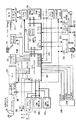
図1は、本発明により、ユーザのコマンドを処理し、ユーザのインタフェース画面(図4)を表示し、且つ記憶された番組ガイドの記録を検索できる装置の概略図である。この装置は、アナログのNTSC方式のテレビジョン信号とインターネット情報の両方を処理することができる。図1の装置は、RF周波数のテレビジョン信号(RF_IN)を受信する第1の入力1100とベースバンドのテレビジョン信号(VIDEO IN)を受信する第2の入力を備える。信号(RF_IN)は、ソース(アンテナまたはケーブル・システム)から供給され、信号(VIDEO IN)は、例えば、ビデオカセット・レコーダ(VCR)から供給される。チューナ1105とIFプロセッサ1130は従来の方法で動作し、信号(RF_IN)内に含まれる特定のテレビジョン信号に同調し、これを復調する。IFプロセッサ1130は同調されたテレビジョン信号の映像番組部分を表すベースバンドのビデオ信号VIDEOを発生する。また、IFプロセッサ1130は、ベースバンドの音声信号を発生し、この音声信号はオーディオ処理部(図示せず)に結合され、更に音声処理される。図1はVIDEO IN(ビデオ入力)1102をベースバンド信号として示しているが、このテレビジョン受信機は、チューナ1105およびIFプロセッサ1130と同様な第2のチューナおよび第2のIFプロセッサを備えて、信号RF_INから、または第2のRF信号源から、第2のベースバンド・ビデオ信号を発生することもできる。
【0018】
また、図1のシステムは、チューナ1105、PIP(Picture‐In‐Picture:ピクチャ‐イン‐ピクチャ)プロセッサ1140、ビデオ信号プロセッサ1155、StarSight(商標)データ処理モジュール1160のような、テレビジョン受信機の構成要素を制御するための主マイクロプロセッサ(mP)(コントローラ)1110を備える。本明細書に於いて、「マイクロプロセッサ」という用語は、マイクロプロセッサ、マイクロコンピュータ、マイクロコントローラ、コントローラを含む種々の装置を表すが、これらに限定されるものではない。主マイクロプロセッサ1110は、このシステムを制御するために、よく知られているI2Cシリアル・データ・バス・プロトコルを利用するシリアル・データ・バスI2C BUSを介してコマンドとデータを送信/受信する。主マイクロプロセッサ1110内部の中央処理装置(CPU)1112は、IRリモコン1125とIR受信部1122によってユーザから供給されるコマンドに応答して、EEPROM1127のようなメモリ内に入っている制御プログラムを実行する。例えば、リモコン1125の「チャンネル・アップ」を起動すると、CPU1112は、チャンネル・データと共に、「チャンネル変更」コマンドをI2C BUSを介しチューナ1105に送信する。その結果、チューナ1105はチャンネル走査リスト内の次のチャンネルに同調する。EEPROM1127内に記憶される制御プログラムの別の例は、以下に説明するように、本発明により図4および図5に(フローチャートの形式で)示す動作を実行するためのソフトウェアである。
【0019】
主マイクロプロセッサ1110は、通信インタフェース装置1113の動作を制御して、情報をインターネットを介してアップロード/ダウンロードできる機能を与える。通信インタフェース装置1113は、例えば、電話回線またはケーブル・テレビジョンのラインを介して、インターネットのプロバイダに接続するためのモデムを含んでいる。この通信機能により、図1に示すシステムは、テレビジョン番組の受信に加えて、Eメール、およびウェブ・ブラウジングのようなインターネット関連の機能が得られる。
【0020】
CPU1112は、主マイクロプロセッサ1110内にあるバス1119を介して主マイクロプロセッサ1110内に含まれる種々の機能を制御する。特に、CPU1112は、補助データ・プロセッサ1115とOSD(On‐Screen Display:オンスクリーン表示)プロセッサ1117を制御する。補助データ・プロセッサ1115は、StarSight(商標)データのような補助データをビデオ信号PIPVから抽出する。
【0021】
既知のフォーマットで番組ガイド情報を提供するStarSight(商標)データは典型的に、ある特定のテレビジョン・チャンネルでのみ受信されるので、テレビジョン受信機はそのチャンネルに同調してStarSight(商標)データを抽出しなければならない。StarSight(商標)データの抽出がテレビジョン受信機の通常の使用を妨げないように、CPU1112はテレビジョン受信機が通常使用されない時間(例えば、午前2時)にのみその特定のチャンネルに同調することにより、StarSight(商標)データの抽出を開始する。その時刻に、CPU1112は、StarSight(商標)データに使用される水平ライン(例えば、16番目のライン)から補助データが抽出されるようにデコーダ1115を構成する。CPU1112は、デコーダ1115からI2C BUSを介してStarSight(商標)モジュール1160への、抽出されたStarSight(商標)データの転送を制御する。このモジュール内にあるプロセッサは、そのデータをフォーマット化し、そのモジュール内のメモリにそのデータを記憶する。StarSight(商標)の電子番組ガイド表示が起動される(例えば、ユーザがリモコン125の特定のキーを起動する)と、CPU1112はフォーマット化されたStarSight(商標)の電子番組ガイド表示データをStarSight(商標)モジュール1160からI2C BUSを介してOSDプロセッサ1117に転送する。
【0022】
OSD(オンスクリーン表示)プロセッサ1117は、従来の方法で動作し、R、G、Bのビデオ信号OSD_RGBを発生する。OSD_RGB信号は、表示装置(図示せず)に結合されると、図4〜図5に示すように、オンスクリーン表示情報を表す表示画像を発生する。また、OSDプロセッサ1117は、制御信号Fast‐Switch(FSW:高速スイッチ)を発生する。制御信号(FSW)は、オンスクリーン表示(OSD)が表示されようとするときに、信号OSD_RGBをこのシステムのビデオ出力信号の中に挿入するために高速スイッチを制御する。従って、ユーザが本発明の種々のユーザ・インタフェース画面をイネーブル(enable:作動化、起動)すると、OSDプロセッサ1117は、それに対応する信号OSD_RGB(メモリ1127内に前に記憶されまたはプログラムされたオンスクリーン表示情報を表す)を発生する。ユーザがリモコン1125の特定のスイッチを起動して電子番組ガイドをイネーブルすると、CPU1112はプロセッサ1117をイネーブルする。それに応答して、プロセッサ1117は、上述したように、前に抽出されて既にメモリ内に記憶されている番組ガイド・データ情報を表す信号OSD_RGBを発生する。また、プロセッサ1117は、電子番組ガイドが表示されようとするとき、それを示す信号FSWを発生する。
【0023】
ビデオ信号プロセッサ(Video Signal Processor:VSP)1155は、輝度/クロマ信号処理のような従来のビデオ信号処理機能を実行する。ビデオ信号プロセッサ1155から発生される出力信号は、表示画像を発生させるために、ディスプレイ、例えば、受像管またはLCD(図1に図示せず)に結合するのに適している。また、ビデオ信号プロセッサ1155は、表示画像内にグラフィックスおよび/またはテキストを含むときに、OSDプロセッサ1117から発生される信号を出力信号路に結合させるために高速スイッチを含んでいる。高速スイッチは、テキスト/グラフィックスを表示するときに、主マイクロプロセッサ1110内のOSDプロセッサ1117から発生される制御信号FSWによって制御される。
【0024】
ビデオ信号プロセッサ1155の入力信号は、PIP(ピクチャ‐イン‐ピクチャ)プロセッサ1140から出力される信号PIPVである。ユーザがPIPモードを起動すると、信号PIPVは大画像(大画面)を表し、その中に小画像(小画面)が挿入される。PIPモードが起動されていないとき、信号PIPVは大画像だけを表し、小画像信号は信号PIPV内に含まれない。PIPプロセッサ1140はビデオ・スイッチ、アナログ/ディジタル変換器(ADC)、RAM、ディジタル/アナログ変換器(DAC)のような、プロセッサ1140内に含まれている機能を使用し従来の方法で、上述した機能を与える。
【0025】
上述したように、電子番組ガイドの表示内に含まれる表示データは、OSDプロセッサ1117により発生され、高速スイッチ信号FSWに応答してビデオ信号プロセッサ1155により出力信号内に含められる。コントローラ(主マイクロプロセッサ)1110が電子番組ガイド表示の起動を検出すると、例えば、ユーザがリモコン1125上の該当するキーを押すと、コントローラ1110はOSDプロセッサ1117に、StarSight(商標)モジュール1160からの番組ガイド・データのような情報を使用する電子番組ガイド表示を発生させる。コントローラ1110はビデオ信号プロセッサ1155に、信号FSWに応答してビデオ画像信号と、OSDプロセッサ1117からの電子番組ガイド表示データとを合成させて、電子番組ガイドを含む表示を発生する。電子番組ガイドは表示領域のすべて、または一部のみ、を占める。
【0026】
電子番組ガイド表示が行われているとき、コントローラ(主マイクロプロセッサ)1110は、EEPROM1127内に記憶された電子番組ガイド制御プログラムを実行する。制御プログラムは、カーソルおよび/またはハイライトのような電子番組ガイド表示内の指標の位置を監視する。ユーザはリモコン1125の方向/選択キーを使用して指標の位置を制御する。あるいは、このシステムはマウスを備えることもできる。コントローラ1110は、マウス・ボタンをクリックするような、選択装置の起動を検出し、表示されている電子番組ガイド・データと連係して現在のカーソルの位置情報を評価し、所望の機能(例えば、ある特定の番組に同調する)を決定する。それに続き、コントローラ1110は選択された機能に関連する制御動作を起動させる。
【0027】
本発明による番組ガイドのプロセスと表示は、ソフトウェアとハードウェアの組合せを使用して実現させることができる。例えば、図1で、電子番組ガイドの表示は、EEPROM1127のようなメモリ内のソフトウェアにより実現される。例えば、ユーザがリモコン1125の電子番組ガイド関連のボタンを押して、電子番組ガイドを起動すると、CPU1112は電子番組ガイドのソフトウェア・ルーチンを実行する。電子番組ガイド表示を発生する一環として、また、CPU1112は、I2Cバスを介しStarSight(商標)モジュール1160内に記憶される電子番組ガイド・データとグラフィックスにアクセスする。EEPROM1127内に記憶される電子番組ガイド・ソフトウェア・ルーチンの制御の下で、CPU1112はOSDプロセッサ1117をイネーブルする。OSDプロセッサ1117は、電子番組ガイド・データとグラフィックスを表すオンスクリーン表示(OSD)を発生するのに適する形式に電子番組ガイド・データをフォーマット化する。OSDプロセッサ1117により発生されるOSDデータは、信号ラインOSD_RGBを介して、ビデオ信号プロセッサ1155に結合される。ビデオ信号プロセッサ1155内の高速スイッチは、信号FSWの制御の下に、電子番組ガイドのOSDデータをビデオ信号プロセッサ1155の出力に結合させる。すなわち、CPU1112により実行されているソフトウェア・ルーチンは、電子番組ガイド・データをいつ(ディスプレイのどの部分に)表示すべきかを決定し、信号FSWを適正な状態に設定して、高速スイッチに、電子番組ガイド・データを出力に結合させる。
【0028】
これまでに説明してきた、図1に例示するシステムの実施例は、主マイクロプロセッサ(mP)(コントローラ)1110に関連する機能を提供するエス・ジイ・エス−トムソン・マイクロエレクトロニクス社(SGS‐Thomson Microelectronics)製のマイクロプロセッサST9296、PIPプロセッサ1140に関連する基本的なPIP機能を提供する三菱電機社(Mitsubishi)製のPIP(ピクチャ‐イン‐ピクチャ)プロセッサM65616、およびビデオ信号プロセッサ1155の機能を提供する三洋電機社(Sanyo)製のビデオ信号プロセッサLA7612から成る。
【0029】
図2は、本発明により、ユーザのコマンドを処理し、ユーザ・インタフェース画面(図4)を表示し、記憶された番組ガイド記録の検索を実行できる装置の別の実施例を示す。図2に示す装置は、放送番組を表すMPEG符号化トランスポート・ストリームを受信するためのMPEGに適合するシステムである。しかしながら、図2のシステムは例示的なものにすぎない。ここで述べるユーザ・インタフェース・システムは他のタイプのディジタル信号処理装置にも応用でき、これにはMPEGに適合しないシステムも含まれ、他のタイプの符号化データ・ストリームも含まれる。他の装置には、例えば、ディジタル・ビデオディスク(DVD)システムおよびMPEGプログラム・ストリーム、およびいわゆる「PCTV」のようなコンピュータとテレビジョンの機能を兼備するシステムも含まれる。また以下に述べるシステムは、放送番組(プログラム)を処理するものとして説明されているがこれは例示的なものにすぎない。本明細書に於いて、「プログラム」という用語は、例えば、電話のメッセージ(伝言)、コンピュータ・プログラム、インターネットのデータ、あるいは他のコミュニケーションなど、あらゆる形態のパケット化されたデータを表すのに使用されている。
【0030】
図2のビデオ受信システムで、ビデオ・データで変調された搬送波はアンテナ10で受信され、入力プロセッサ15で処理される。その結果生じるディジタル出力信号は復調器20で復調され、デコーダ30で復号化される。デコーダ30からの出力はリモコン125からのコマンドに応答するトランスポート・システム25で処理される。トランスポート・システム25は圧縮されたデータ出力を、記憶し更に復号化しあるいは他の装置へ伝送するために、供給する。
【0031】
ビデオ・デコーダ85とオーディオ・デコーダ80はそれぞれ、トランスポート・システム25からの圧縮されたデータを復号化し、表示用出力を供給する。高速データ・ポート75は圧縮されたデータを、トランスポート・システム25からコンピュータまたは高精細度テレビジョン(HDTV)受信機のような他の装置に伝送するためのインタフェースとなる。記憶装置90はトランスポート・システム25からの圧縮されたデータを記憶媒体105に記憶する。トランスポート・システム25で処理し、復号化し、他の装置に伝送し、あるいは異なる記憶媒体(図面を簡略化するために図示せず)に記憶するために、プレイバック(再生)・モードで、記憶装置90は記憶媒体105からの圧縮されたデータの再生をサポートする。
【0032】
図2において、アンテナ10で受信されたビデオ・データで変調された搬送波はディジタル形式に変換され、入力プロセッサ15で処理される。入力プロセッサ15は無線周波(RF)チューナと中間周波(IF)ミクサ/増幅段を含み、入力ビデオ信号を、更に処理するのに適する比較的低い周波数帯に変換する。その結果生じるディジタル出力信号は復調器20で復調され、デコーダ30で復号化される。デコーダ30からの出力はトランスポート・システム25で更に処理される。
【0033】
サービス検出器33のマルチプレクサ(MUX)37は選択器35を介してデコーダ30からの出力を供給されるか、またはデコーダ30の出力はデスクランブル(descramble:解読)装置40で更に処理される。デスクランブル(解読)装置40は例えば、ISO7816およびNRSS(National Renewable Security Standards:更新可能な国家安全標準)委員会の標準に従うスマート・カードのような取外し可能な装置である(NRSSの取外し可能な条件付きアクセス・システムは、EIA草案文書IS‐679、プロジェクトPN‐3639に規定されている)。選択器35は、挿入可能な互換性のあるデスクランブル・カードの存在を検出し、カードが受像機内に挿入されているときに限り、デスクランブル装置40の出力をMUX37に供給する。カードが挿入されていなければ、選択器35はデコーダ30からの出力をMUX37に供給する。この挿入可能なカードが存在すると、デスクランブル装置40は、追加的なプレミアム番組チャンネルをデスクランブルし、追加的な番組サービスを視聴者に提供できる。この実施例においては、NRSS解読装置40とスマート・カード・ユニット130(スマード・カード・ユニット130については後で述べる)は、同じトランスポート・システム25のインタフェースを共有しており、一度に挿入できるのはNRSSカードまたはスマート・カードの何れかのみである。
【0034】
選択器35からMUX37に供給されるデータは、MPEGシステムの標準第2.4項に規定される、MPEGに準拠するパケット化トランスポート・データ・ストリームの形態であり、1つまたはそれ以上の番組チャンネルのデータ内容と番組ガイド情報を含んでいる。特定の番組チャンネルを含む個々のパケットは、PID(Packet IDentifier:パケット識別子)により識別される。トランスポート・ストリームは、PSI(Program Specific Information:番組特定情報)を含み、番組特定情報を使用してパケット識別子を識別し、個々のデータ・パケットをアセンブル(assemble)し、パケット化データ・ストリームを含むすべての番組チャンネルの内容を再生する。システム・コントローラ115の制御下で、トランスポート・システム25は、通信インタフェース装置116を介して、入力トランスポート・ストリーム、記憶装置90またはインターネットのプロバイダから、番組ガイド情報を獲得し、照合(collate)する。特定の番組チャンネルの内容、または番組ガイド情報含む個々のパケットは、ヘッダ情報内に含まれているPID(パケット識別子)によって識別される。番組ガイド情報内に含まれる番組の説明は、種々異なる番組の説明的項目(タイトル、スター、格付けなど)から成る。
【0035】
図2に示す受像機内に組み込まれるユーザ・インタフェースにより、ユーザはオンスクリーン表示(OSD)メニューから所定の機能を選択することによって種々の機能を起動させることができる。OSDメニューには、上述した電子番組ガイド(EPG)、および以下に述べる他の機能も含まれる。
【0036】
オンスクリーン表示(OSD)メニューに表示される情報を表すデータは、テキスト/グラフィックスを表す記憶されたオンスクリーン表示情報、記憶された番組ガイド情報、および入力信号によって受信される番組ガイドとテキスト/グラフィックス情報に応答して、また図4〜図5に例示する制御プログラムに従って、システム・コントローラ115より発生される。ソフトウェア制御プログラムは、例えば、システム・コントローラ115の埋込みメモリ(図示せず)内に記憶される。
【0037】
リモコン125(または、マウスのような他の選択手段)を使用して、ユーザは視聴しようとする番組、記憶(例えば、録画)しようとする番組、記憶媒体のタイプおよび記憶方法のような項目をOSDメニューから選択できる。システム・コントローラ115は、インタフェース120を介して提供される選択情報を使用して、記憶/表示用に番組を選択し、選択された記憶装置/媒体に適する番組特定情報を発生するようにトランスポート・システム25を構成する。システム・コントローラ115は、データ・バスを介してトランスポート・システム25の要素45、47、50、55、65、95の内部に制御レジスタの値を設定し、制御信号CでMUX37と110を介する信号路を選択することによって、これらの要素を構成する。
【0038】
制御信号Cに応答して、MUX37は選択器35からトランスポート・ストリームを選択し、またはプレイバック・モードにおいて、記憶インタフェース95を介して記憶装置90から再生されるデータ・ストリームを選択する。通常の、非再生動作において、ユーザが視聴するために選択した番組を含んでいるデータ・パケットは、それらのパケット識別子により選択装置45によって識別される。もし、パケットが暗号化されていることを、選択された番組パケットのヘッダ・データ内にある暗号化指標が示すならば、選択装置45はそのパケットを解読装置50に供給する。もしそうでなければ、選択装置45は非暗号化パケットをトランスポート・デコーダ55に供給する。同様にして、ユーザが記憶用に選択した番組を含んでいるデータ・パケットは、それらのパケット識別子により選択装置47によって識別される。選択装置47は、パケット・ヘッダの暗号化指標に基づいて、暗号化(encrypted)パケットを解読装置50に供給するか、または非暗号化(non‐encrypted)パケットをMUX110に供給する。
【0039】
解読装置40と50の機能は、NRSS標準に適合する1個の取外し可能なスマート・カードで実現される。この方法で、もしサービス・プロバイダが暗号化方式を変更することにするか、または、例えば、別のサービスをデスクランブル(descramble:解読)するために、セキュリティ・システムを容易に変更することにするならば、すべてのセキュリティ関連の機能は、容易に交換できる取外し可能なユニット(装置)内に収められる。
【0040】
選択装置45および47はパケット識別子検出フィルタを使用する。パケット識別子検出フィルタはMUX37から供給される入来パケットのパケット識別子を、システム・コントローラ115によって選択装置45と47内部の制御レジスタ内に予めロードされたパケット識別子の値とマッチさせる。予めロード(pre‐load)されたこれらのパケット識別子は、これから記憶されるデータ・パケットと、ビデオ画像の発生のために復号化されるデータ・パケットとを識別するために選択装置47と45内に記憶される。予めロードされたパケット識別子は選択装置45と47内のルックアップ・テーブル内に記憶される。パケット識別子ルックアップ・テーブルは、予めロードされた各パケット識別子と暗号化キー(key)を関連づける選択装置45と47内の暗号化キー・テーブルにメモリ・マップされる。メモリ・マップ(memory map)されたパケット識別子および暗号化キーのルックアップ・テーブルによって、選択装置45と47は、予めロードされたパケット識別子を含む暗号化パケットを、それらの解読を可能にする関連する暗号化キーとマッチさせる。非暗号化パケットは関連する暗号化キーを持たない。選択装置45と47は、識別されたパケットおよびそれに関連する暗号化キーを解読装置50に供給する。選択装置45内のパケット識別子ルックアップ・テーブルは、予めロードされたパケット識別子を含むパケットをパケット・バッファ60内の対応する宛先バッファの位置とマッチさせる宛先テーブルにメモリ・マップされる。ユーザが視聴または記憶用に選択する番組に関連する、暗号化キーおよび宛先バッファの位置のアドレスは、システム・コントローラ115により割り当てられたパケット識別子と共に選択装置45と47の中に予めロードされる。暗号化キーは、入力データ・ストリームから抽出される暗号化コードからISO7816‐3に従うスマート・カード・システム130によって発生される。暗号化キーの発生は、入力データ・ストリーム内のコード化情報から決定され且つ挿入可能なスマート・カード自体に予め記憶される加入者の資格を条件とする(国際標準機構の文書ISO7816‐3、1989、はスマート・カード・システムに関するインタフェースおよび信号の構成について規定している)。
【0041】
選択装置45と47より解読装置50に供給されるパケットは、商務省の国家技術情報サービスが提供する連邦情報標準(Federal Information Processing Standards:FIPS)刊行物46、74、81で規定するデータ暗号化標準(Data Encryption Standards:DES)のような暗号化技術を使用して暗号化される。解読装置50は暗号化されたパケットを、選択された暗号化アルゴリズムに適する解読技術を利用することにより、対応する暗号化キー(選択装置45と47から供給される)を使用して暗号化されたパケットを解読する。解読装置50からの解読されたパケット、および表示用の番組を含む選択装置45からの非暗号化パケットはデコーダ55に供給される。解読装置50からの解読されたパケット、および記憶用の番組を含む選択装置47からの非暗号化パケットはMUX110に供給される。
【0042】
パケット・バッファ装置60は、システム・コントローラ115でアクセスできる4個のパケット・バッファを含んでいる。これらのバッファのうちの1つは、システム・コントローラ115で使用されるデータの保持に当てられ、他の3個のバッファは、アプリケーション装置75、80、85で使用されるパケットの保持に当てられる。システム・コントローラ115による、そしてアプリケーション・インタフェース70による、パケット・バッファ装置60内部の4個のバッファ内に記憶されるパケットへのアクセスはバッファ制御装置65で制御される。選択装置45は、復号化のために選択装置45で識別される各パケットについて宛先フラグ(flag)を制御装置65に供給する。これらのフラグは、識別されたパケットについて、パケット・バッファ装置60の個々の宛先位置を示し、制御装置65によって内部のメモリ・テーブルに記憶される。制御装置65は先入れ先出し(First‐In‐First‐Out:FIFO)の原理に基づいて、バッファ60内に記憶されるパケットに関連する一連の読出し/書込みポインタ(pointers)を決定する。書込みポインタは宛先フラグと連係して、選択装置45または50からの識別されたパケットが、パケット・バッファ装置60内の該当する宛先バッファ内の次の空位置に順次に記憶されるようにする。読出しポインタは、パケット・バッファ装置60内の該当する宛先バッファからのパケットがシステム・コントローラ115とアプリケーション・インタフェース70により順次に読み出されるようにする。
【0043】
選択装置45と50よりデコーダ55に供給される非暗号化パケットと解読されたパケットは、MPEGシステム標準の2.4.3.2項に規定されるトランスポート・ヘッダを含んでいる。デコーダ55はこのトランスポート・ヘッダから、非暗号化パケットと解読されたパケットが(MPEGシステム標準による)アダプテーション・フィールド(adaptation field:適合化フィールド)を含んでいるか判断する。適合化フィールドには、例えば、コンテンツ(content)パケットの復号化および同期を可能にする、プログラム・クロック・レファレンス(PCR:Program Clock Reference)を含むタイミング情報が入っている。適合化フィールドを含むパケットである、タイミング情報パケットを検出すると、デコーダ55は、システム・インタラプト(interrupt)を設定することによりインタラプト機構を介して、システム・コントローラ115にそのパケットが受信されたことを信号で合図する。更に、デコーダ55は、装置65内のタイミング・パケット宛先フラグを変更し、そのパケットをパケット・バッファ装置60に供給する。装置65の宛先フラグを変更することにより、バッファ制御装置65は、デコーダ55から供給されるタイミング情報パケットを、アプリケーション・バッファの位置に代り、コントローラが使用するデータの保持に当てられたパケット・バッファ装置60のバッファ位置に方向転換する。
【0044】
デコーダ55で設定されたシステム・インタラプトを受信すると、システム・コントローラ115はタイミング情報とPCR値を読み取り、内部メモリの中に記憶する。連続するタイミング情報パケットのPCR値は、トランスポート・システム25のマスタ・クロック(27MHz)の調節のためにシステム・コントローラ115で使用される。システム・コントローラ115より発生される、連続するパケットを受信する時間間隔の、PCRをベースとする推定値とマスタ・クロックをベースとする推定値との差はトランスポート・システム25のマスタ・クロックの調節に使用される。このため、システム・コントローラ115は得られた時間推定値の差を利用して、マスタ・クロックの発生に使用される電圧制御発振器の入力制御電圧を調節する。システム・コントローラ115は、タイミング情報を内部メモリに記憶した後、システム・インタラプトをリセットする。
【0045】
番組内容(音声、映像、キャプション、その他の情報)を含んでいる選択装置45および解読装置50からデコーダ55で受信されるパケットは、装置65によってデコーダ55から、パケット・バッファ60内の指定されたアプリケーション装置のバッファに向けられる。アプリケーション制御装置70は音声、映像、キャプションその他のデータを、バッファ60内の指定されたバッファから順次に検索し、そのデータを対応するアプリケーション装置75、80、85に供給する。アプリケーション装置は、オーディオ・デコーダ80とビデオ・デコーダ85および高速データ・ポート75から成る。例えば、システム・コントローラ115より発生される複合番組ガイドに対応するパケット・データは、ビデオ・デコーダ85に搬送され、ビデオ・デコーダ85に接続されるモニタ(図示せず)に表示するのに適するビデオ信号にフォーマット化される。またデータ・ポート75は、コンピュータに、コンピュータ・プログラムのような高速データを供給するのに使用される。ポート75は、データをHDTVデコーダに出力して、選択された番組または番組ガイドに対応する画像の表示にも使用される。
【0046】
PSI情報を含むパケットは、パケット・バッファ装置60内のシステム・コントローラ115のバッファのために予定されるものとして、選択装置45で認識される。この番組特定情報パケットは、番組内容を含むパケットについて述べたのと同様に、選択装置45、50、55を介して、バッファ制御装置65によってこのバッファに向けられる。システム・コントローラ115はパケット・バッファ装置60からその番組特定情報を読み出し、それを内部メモリに記憶する。
【0047】
システム・コントローラ115は、記憶された番組特定情報からCPSI(condensed PSI:圧縮された番組特定情報)を発生し、そのCPSIを、選択可能な記憶媒体に記憶するのに適するパケット化されたデータ・ストリーム内に組み入れる。パケットの識別および方向は、前述したように、選択装置45と選択装置47のパケット識別子、宛先/暗号化キー・ルックアップ・テーブルおよび制御装置65の機能と連係して、システム・コントローラ115で支配される。
【0048】
更に、システム・コントローラ115は、インタフェース装置1113(図1)と同様に動作する通信インタフェース装置116に結合される。すなわち、インタフェース装置116により、インターネットで情報をアップロード/ダウンロードできる。通信インタフェース装置116は、電話回線またはケーブル・テレビジョンのラインを介してインターネットのサービス・プロバイダに接続するモデムを含んでいる。このため、図2に示すシステムはテレビジョン番組の受信に加えて、Eメール、およびウェブ・ブラウジングのようなインターネット関連の機能が得られる。
【0049】
図3は、図2に全体を示し詳細に説明した電子装置の具体的な実施例であり、ヒューズ・エレクトロニクス社(Hughes Electronics)より提供される衛星サービス、DIRECTV(商標)を受信するためにアメリカ合衆国インディアナ州インディアナポリスのトムソン・コンシューマ・エレクトロニクス社(Thomson Consumer Electronics)が設計・製作した衛星受信機セットトップ・ボックスを示す。
【0050】
図3に示すように、セットトップ・ボックスはチューナ301を備える。チューナ301は、衛星アンテナ317より衛星RF信号(950〜1450MHz)を受信しこれに同調する。同調されたアナログ信号はリンク・モジュール302に出力され更に処理される。リンク・モジュール302は、アナログ信号の瀘波と調整、およびアナログ信号からディジタル出力信号DATAへの変換を含む、チューナ301からの同調されたアナログ信号I_OUTとQ_OUTの更なる処理を実行する。リンク・モジュール302は集積回路(IC)として実現される。このリンク・モジュールICはフランス、グルノーブルのエス・ジイ・エス−トムソン・マイクロエレロニクス社(SGS‐Thomson Microelectronics)で製作される。
【0051】
リンク・モジュール302からのディジタル出力DATAは、トランスポート装置303が認識して処理できるパケット化されたデータ・ストリームから成る。このデータ・ストリーム(図2に関連して詳細に述べる)は、番組ガイド・データ情報、およびDIRECTV(商標)からの衛星放送サービスの番組チャンネルのデータ内容を含んでいる。番組ガイド・データは、「等級」で示される番組のタイプ(例えば、音声のみ、映像のみ、など)に関連する情報を含んでいる。
【0052】
トランスポート装置303の機能は、図2に示し既に説明したトランスポート・システム25と同じである。上述したように、トランスポート装置303はヘッダ内に含まれるPID(Packet IDentifier:パケット識別子)により、パケット化されたデータ・ストリームを処理する。処理されたデータ・ストリームは、MPEGに適合する圧縮された音声/映像パケットにフォーマット化され、MPEGデコーダ304に結合され、更に処理される。
【0053】
トランスポート装置303は、ARM(アドバンストRISCマイクロプロセッサ:Advanced RISC Microprocessor)315によって制御される。ARM315は、RISCをベースとするマイクロプロセッサである。ARMプロセッサ315はROM308内に在る制御ソフトウェアを実行する。このソフトウェアの構成要素は、例えば、図4〜図5に示す制御プログラムであり、以下に説明するように本発明の態様に従って、ユーザ・インタフェースのコマンドを処理するとともに、オンスクリーン表示情報を表示する。
【0054】
トランスポート装置303は典型的に、集積回路として実現される。好ましい具体例は、エス・ジイ・エス−トムソン・マイクロエレクトロニクス社(SGS‐Thomson Microelectronics)が製作するIC(部品番号ST15273‐810または15103‐65C)である。
【0055】
トランスポート装置303からの、MPEGに適合する圧縮されたオーディオ/ビデオ・パケットはMPEGデコーダ304に送られる。デコーダ304はトランスポート装置303からの圧縮されたMPEGデータ・ストリームを復号化する。デコーダ304は次に、関連するオーディオ・ストリームを出力し、この出力は音声ディジタル/アナログ変換器(DAC)305によって更に処理され、このディジタル音声データはアナログ音声に変換される。また、デコーダ304は、映像の画素情報を表すディジタル・ビデオ・データをNTSCエンコーダ306に出力する。NTSCエンコーダ306は、このビデオ・データを更に処理して、NTSCに適合するアナログ・ビデオ信号とし、ビデオ画像が通常のNTSCテレビジョン画面に表示される。上述したのMPEGデコーダは集積回路として実現される。1つの具体例は、エス・ジイ・エス−トムソン・マイクロエレクトロニクス社によって製作されたMPEGデコーダIC(部品番号ST13520)である。
【0056】
MPEGデコーダ304の中には、OSDプロセッサ320が含まれている。OSDプロセッサ320は、記憶されたオンスクリーン表示情報を含むSDRAM316からデータを読み出す。オンスクリーン表示情報はビットマップ方式のOSDグラフィックス/テキスト画像に対応する。OSDプロセッサは、従来の方式でARMマイクロプロセッサ315の制御下で、OSD画像の各画素の色合い/透明度を変化させることができる。
【0057】
また、OSDプロセッサは、ARMマイクロプロセッサ315の制御下で、番組ガイドを発生させる。この実施例で、ガイド表示を発生するユーザのリクエストを検出すると、ARMマイクロプロセッサ315は、番組ガイド情報のプロバイダから供給されるデータ・ストリームから得られる番組ガイド・データ情報を処理して、そのガイド・データ情報を、「グリッド・ガイド」に対応するOSD画素データにフォーマット化する。トランスポート装置303からのOSD画素データは次に、MPEGオーディオ/ビデオ・デコーダ304内のOSDプロセッサ320に送られ、前述したように、ガイド画像を発生する。
【0058】
低速データ・ポート330は、番組を録画するためにVCRを制御するIRブラスタ(図示せず)に接続するために使用される。前述したように、IRブラスタ(blaster)は基本的に、図3に示す衛星受信機によって制御される、プログラム可能な、VCRリモコン・エミュレータである。これは、接続されたVCRのリモート・センサの前方に配置され、ユーザが入力するタイマーの画面情報により、衛星受信機の制御下で「オン」および「録画」のようなコマンドを適正な時期に送信する。
【0059】
図3の付加的機能ブロックにはモデム307が含まれる。モデム307は通信インタフェース装置(図2)に対応し、インターネットにアクセスする。CAM(Conditional Access Module:条件付きアクセス・モジュール)309は、NRSS解読装置(図2)に対応し、CA情報を提供する。広帯域データ・モジュール310は高速データ・ポート75(図2)に対応し、HDTVデコーダまたはコンピュータに高速データ・アクセスを行う。キーボード/IR受信モジュール312はリモート・ユニット(遠隔装置)インタフェース120(図2)に対応し、ユーザ制御装置314からユーザ制御コマンドを受信する。ディジタルAVバス・モジュール313はI/Oポート100(図2)に対応し、VCRまたはDVDプレーヤのような外部装置に接続する。
【0060】
図5は、例示的な制御プログラムの高レベル・フローチャートである。この制御プログラムは、本発明により、図1〜図3に示す装置のうちの1つによって、または他の適当にプログラムされた電子ホスト装置によって実行される。ここで使用される、「電子ホスト装置」はテレビジョン受信機またはパーソナル・コンピュータに限定されず、その合成物(例えば、PCTV)、ケーブル・テレビジョンのコンバータ・ボックス、適当に装備されたオーディオビジュアル番組レコーダ(例:VCR)、衛星テレビジョン/データ信号コンバータ、番組ガイド受信装置など(テレビジョン受信機またはパーソナル・コンピュータ内に組み込まれているとか、その外部に接続されているとかに関わりなく)が含まれる。この例示的な制御プログラム内に埋め込まれているプロセスは、ハードウェア、ソフトウェア、またはそれを組み合せて実現されることが理解される。当業者はこのフローチャートおよび以下の説明から、図1〜図3に示すシステムの1つによって、あるいは他の適当にプログラムされた電子ホスト装置によってこの制御プログラムを実行すると、本発明により実質的に同じ特徴と利点が得られることを容易に認識するであろう。従って冗長を避けるため、図5の制御プログラムおよび図4のユーザ・インタフェースは、図2に例示するハードウェアの実現に関してのみ以下に説明する。
【0061】
アプリケーション・インタフェース70は、システム・コントローラ115の制御下で、新しいユーザ・プロファイル・インタフェース(図4に示す)を発生させる。この新しいユーザ・プロファイル・インタフェースを発生させるには、新しいユーザ・プロファイル・インタフェースを起動させる(例えば、システムの所有者がリモコン125の特定のキーを起動するか、または別のユーザ・インタフェースにおいて選択を行い、新しいユーザ・プロファイルを作成する)。このような起動に応えて、システム・コントローラ115は新しいユーザ・プロファイル・インタフェースのデータをアプリケーション・インタフェース70に転送し、アプリケーション・インタフェース70は次に、対応する表示情報をビデオ・デコーダに出力し、ディスプレイ・モジュール11に表示する(図4)。
【0062】
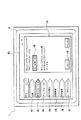
図4に関して、ディスプレイ・モジュール11の表示エリア18内に新しいユーザ・プロファイル・インタフェース400が表示される。システム・コントローラ115は、新ユーザ・プロファイル・インタフェース400内の指標(カーソル/ハイライト)の位置を監視する。システムの所有者は、リモコン125の方向/選択キーによって指標の位置を制御する。この位置指標を使用することによって、システムの所有者は新ユーザ・プロファイル・インタフェース400と対話することができる、選択を行って、リモコン125で新ユーザ・プロファイル・インタフェース400の中に選択を入力することができる。
【0063】
本発明によれば、新しいユーザ・プロファイル・インタフェース400は、新しいユーザ・プロファイルの作成に使用される。新ユーザ・プロファイル・インタフェース400は、新ユーザ名のボタン401、設定コピーのボタン402、ユーザ・プロファイル設定ボタン403〜406、ユーザ・ロック(lock)ボタン407、および制御フィールド408から成る。システムの所有者がボタン401〜407のどれかをハイライトすると、ハイライトされたボタンに対応する対話形式の表示が制御フィールド408に現れる。例えば、システムの所有者が新ユーザ名のボタン401をハイライトすると、新しいユーザ・プロファイルが作成されているそのユーザの名前を入れる対話形式の表示が制御フィールド408内に現れる。次に、リモコン125でコマンドを入力して新しいユーザの名前を入れることができる。同様にして、ユーザ・プロファイル設定のボタン403〜406のどれかをハイライトすると、そのボタンに関連して親の管理に関するデータを入力する対話形式の表示が制御フィールド408に現れるので、次に、リモコン125でローカル変数(local variables)をフィールドに入力できる。システムの所有者がフィールドに入力したローカル変数は、プロファイルが作成されているその新しいユーザ(子)に対する親(保護者)の拘束(parental restraints)および制限を定める。
【0064】
もしシステムの所有者が、ユーザ・プロファイル設定のボタン403〜406を選択して変数をそれぞれのフィールドに入力したくなければ、設定をコピーするボタン402をハイライトすればよい。設定コピーのボタン402をハイライトすると(図4)、不揮発性メモリ内に前に記憶されたユーザ・プロファイルに容易にアクセスできる対話形式の表示が制御フィールド408内に現れる。制御フィールド408内に、以前作成されて記憶されているすべてのユーザ・プロファイルのリスト409が自動的に発生されるので、リモコン125で、記憶されているユーザ・プロファイルのうち、その設定をコピーしたいと思うユーザのプロファイルをハイライトして選択できる。記憶されているユーザのプロファイルをハイライトしてリスト409から選択すると、次に、コピー・ボタン410を起動させる。コピー・ボタン410を起動させると、選択されたユーザ・プロファイルが、それが記憶されている非揮発性メモリから検索される。記憶されているユーザ・プロファイルに対し既に設定されている親の種々の拘束に対応するデータが、ボタン403〜406(上述した)に関連して、対応するデータ入力フィールドにコピーされるので、新しいユーザ・プロファイル作成のために各データ入力フィールドに個々に書き入れる必要はない。選択されたユーザ・プロファイルに設定される親の拘束(子に対する)は新ユーザ・プロファイルの空白フィールド内にローカル変数として書き込まれる。
【0065】
オプションとして、システムの所有者は、変数をそれぞれ入力する場合と同様に、コピーされた設定/変数を編集することができ、次に、その新しいユーザ・プロファイルを不揮発性メモリに記憶することができる。
【0066】
上述した「設定をコピーする」機能では、1つのプロファイルを完全に設定してから、それらの設定および制限を追加的なプロファイルにコピーすることによって、システムの所有者は多数のプロファイルを設定する際の冗長なステップを排除できる。システムの所有者は、新プロファイルの設定事項を、新プロファイルのユーザの年齢または成熟度に基づいて変更することができる。例えば、本システムの所有者は、7歳の子供が使用するプロファイル1を設定する。制限はかなり厳しくなると思われる。システムの所有者は次に、これらの設定および制限を、10歳の子供が使用する新しいプロファイル2にコピーすることができ、次に、これらの制限の幾つかを,比較的年上の子供のプロファイル用に緩和することができる。プロファイル2の設定に要する時間は、全く白紙のプロファイルから始めたときよりも相当に短縮される。
【0067】
図5は、本発明の態様に従う特徴を実現するために図2のシステム・コントローラ115によって実行される制御プログラムのフローチャートを例示する。図5のプロセスのステップは、図4について上述されているので、冗長を避けるためにステップ500〜530については述べない。
【0068】
前述した説明は、本発明の実施例を開示し記載したものにすぎない。当業者が理解するように、本発明は、本発明の精神または本質から離れることなく他の形態でも実現できる。従って、ここに開示する発明は、クレームに記載の本発明の範囲について述べたものであるが、それを限定するものではない。
【図面の簡単な説明】
【0069】
【図1】本発明により、ユーザのコマンドを処理し、且つユーザ・インタフェース画面を表示することのできる装置の概略図である。
【図2】本発明により、ユーザのコマンドを処理し、且つユーザ・インタフェース画面を表示するのに適するディジタル・ビデオ処理装置の概略図である。
【図3】図2に全体を示す装置の具体的な実施例の概略図である。
【図4】本発明により、新しいユーザ・プロファイルを作成するためのユーザ・インタフェースを表示するディスプレイ・モジュールである。
【図5】本発明により新ユーザ・プロファイルを作成する方法のフローチャートである。【Technical field】
[0001]
In general, the present invention relates to video processing, and more particularly, to a system and method for creating user profiles.
[Background Art]
[0002]
With the advent of cable television, satellite broadcasting systems, and other television program broadcasting systems, there are a large number of programs that television viewers seek to select. Many of these systems utilize an Electronic Program Guide (EPG) system (including hardware, software, and download / store functions). The electronic program guide is a two-way on-screen display (On-Screen Display: OSD) equivalent to a television program section found in newspapers and other print media. The electronic program guide can provide up to 20 different types of information for each program within the time frame covered by the electronic program guide. In a typical electronic program guide system, an electronic host device stores records of upcoming television programs within the electronic program guide time frame. Each record contains program identification data specific to a television program scheduled to be broadcast soon. This program identification data includes program title, start time, end time, duration, rating, remaining time, content, cost, topic, theme, actor, writer, production studio, awards, keywords, broadcast date, director, simple It contains a simple explanation. These records are updated periodically, records of previously broadcasted programs are erased, and over time new records are added for upcoming programs that fall within the electronic program guide timeframe.
[0003]
U.S. Pat. No. 5,515,106 (Chaney) describes the structure of data packets required to implement an electronic program guide system. The data packet contains channel information (eg, channel name, call code, channel number, type, etc.) and program identification information associated with the program (eg, content, title, rating, star, duration, cost, etc.). , From a program guide database provider to a receiving device such as a television receiver.
[0004]
In many current systems, a user of the system can set up multiple user profiles, and multiple system / program parameters are automatically configured for each user. These user profile parameters include, for each user, a favorite channel list, language settings, video / audio settings, pay-per-view management, parental control for children, etc. Is included. In each user profile, parental control further includes items that the user can select: (1) the amount of time a particular viewer is allowed to watch television on a weekday or weekend; The amount that can be spent on pay-per-view programs per program or per month, (3) specific channels that specific viewers should access, and (4) satellite programs that specific viewers can access on weekends or weekdays. Includes the number of hours that can be seen.
[0005]
However, setting up a new user profile using current methods and systems can be time consuming. In current systems, a number of parameters must be selected when the system owner (owner: parent) sets up a new profile. These parameters include rating limits for movies, rating limits for television programs, setting limits for DSLVFV content, determining whether to allow viewing of programs whose content is not rated, spending limits per event, and Set monthly spending limits, set the maximum viewing time on weekends and weekdays, set the number of hours you can watch satellite programs on weekends and weekdays, and access specific channels (more than 200 channels) Setting a channel list to determine whether to block or allow.
DISCLOSURE OF THE INVENTION
[0006]
(Summary of the Invention)
The present inventors have recognized that the fields currently available for user profiles (including parental management parameters) are numerous, setting up a new user profile is cumbersome and time consuming. Further, if the owner of the system wishes to create a second user profile, the entire procedure is performed, even if the second user profile is substantially similar to the first profile already created and stored. Must be repeated many times, which is even more problematic.
[0007]
Attempts have been made to reduce the set time required to create a user profile, for example, to allow a user to exclude all unsubscribed channels from a profile channel list. Still, the setup time for the remaining limit is not reduced, and the system owner must block or allow access to each subscribed channel that remains on the list after removing the unsubscribed channel, Then, as a practical matter, it is hardly effective to shorten the redundant setting required for each profile.
[0008]
These and other problems are solved by the present invention. One aspect of the present invention is an apparatus for use in a video device, comprising: a storage medium having a storage location for storing a profile of a user of an entertainment system; a new medium having a field for input data stored in the storage medium. A user interface for creating a user profile, said user interface for creating a new user profile including an option for a user to select and copy data from a stored user profile, and a stored user profile; Means for selecting a profile, copying data selected from the stored user profiles to corresponding fields in the new user profile, and storing the new user profile in a storage location.
[0009]
Data that is stored and copied from the selected user profile to a field of the user interface can be edited. Also, the stored user profile preferably includes user identification and data relating to one or more of a rating limit for television programs, a list of channels, spending limits, viewing time, and parental or child status. . In addition, the user interface may include a television screen and an input module for selecting options displayed on the screen to place alphanumeric data in the field.
[0010]
The user interface may include means for placing the data in the field and making the selection. Means for selecting a stored user profile, copying data selected from the stored user profile to a corresponding field in the new user profile, and storing the new user profile in the storage location, the processor comprising: Consists of Also, the user profile is stored in the non-volatile memory.
[0011]
The means for selecting a stored user profile, copying data selected from the stored user profile to a corresponding field in the new user profile, and storing the new user profile in the storage location Wherein the user profile is stored in non-volatile memory, the user interface comprises a television screen, and an input module for selecting options displayed on the television screen to place alphanumeric data in the field; It consists of the identity of the user and a user profile that includes one or more of a rating limit for television programs, a list of channels, spending limits, viewing time, and parental or child status.
[0012]
In another embodiment, the invention is a television device having a parental management system with a user profile creation device, wherein the storage medium has a storage location for storing a user profile of an entertainment system. A user interface for creating a new user profile having fields for input data stored therein, creating a new user profile including an option for a user to select and copy data from the stored user profile Selecting the stored user profile, and copying the data selected from the stored user profile to a corresponding field in the new user profile, thereby creating a new user profile. Memorize in storage location That means, consisting of.
[0013]
In yet another embodiment, the invention is a method of creating a new user profile on an entertainment device, the method comprising accessing a stored list of user profiles comprising data arranged in fields. Displaying a new user profile interface having the following steps: selecting a stored user profile; copying data from fields of the selected user profile to corresponding fields of the new user profile interface. And steps.
[0014]
The fields preferably include the user's identity and one or more of a rating limit for the television program, a list of channels, a spending limit, viewing time, and parent or child status.
[0015]
Preferably, the method further comprises the step of storing the new user profile in a non-volatile memory. Also, the method of the present invention preferably includes the further step of editing the data copied into the fields of the new user profile interface.
[0016]
Finally, the method of the present invention comprises the steps of selecting a stored user profile from a non-volatile memory, and storing the selected stored user profile in the non-volatile memory with a corresponding local user profile of the new user profile. Preferably, the method comprises the steps of copying to variables, editing local variables, and storing the local variables as new user profiles in non-volatile memory.
BEST MODE FOR CARRYING OUT THE INVENTION
[0017]
FIG. 1 is a schematic diagram of an apparatus capable of processing a user command, displaying a user interface screen (FIG. 4), and retrieving stored program guide records according to the present invention. This device can process both analog NTSC television signals and Internet information. The apparatus of FIG. 1 includes a
[0018]
The system of FIG. 1 also includes a television receiver, such as a
[0019]
The
[0020]
The
[0021]
Since StarSight ™ data, which provides program guide information in a known format, is typically received only on a particular television channel, the television receiver tunes to that channel and provides the StarSight ™ data. Must be extracted. The
[0022]
OSD (On Screen Display)
[0023]
A Video Signal Processor (VSP) 1155 performs conventional video signal processing functions such as luminance / chroma signal processing. The output signal generated from
[0024]
The input signal of the
[0025]
As described above, the display data contained within the display of the electronic program guide is generated by the
[0026]
When the electronic program guide display is being performed, the controller (main microprocessor) 1110 executes the electronic program guide control program stored in the
[0027]
The process and display of the program guide according to the present invention can be implemented using a combination of software and hardware. For example, in FIG. 1, the display of the electronic program guide is realized by software in a memory such as the
[0028]
The embodiment of the system illustrated in FIG. 1 that has been described so far is a SGS-Thomson microelectronics (SGS-Thomson) company that provides functionality related to the main microprocessor (mP) (controller) 1110. Provides the functions of a microprocessor ST9296 manufactured by Microelectronics, a picture-in-picture (MIP) processor M65616 manufactured by Mitsubishi, and a
[0029]
FIG. 2 illustrates another embodiment of an apparatus that can process user commands, display a user interface screen (FIG. 4), and perform searches of stored program guide recordings, in accordance with the present invention. The device shown in FIG. 2 is an MPEG compliant system for receiving an MPEG encoded transport stream representing a broadcast program. However, the system of FIG. 2 is merely exemplary. The user interface systems described herein can be applied to other types of digital signal processing devices, including systems that are not MPEG compliant, and include other types of encoded data streams. Other devices include, for example, digital video disc (DVD) systems and MPEG program streams, and systems that combine computer and television functions, such as so-called "PCTV". Also, the system described below is described as processing broadcast programs (programs), but this is merely exemplary. As used herein, the term "program" is used to describe any form of packetized data, such as, for example, telephone messages (messages), computer programs, Internet data, or other communications. Have been.
[0030]
In the video receiving system of FIG. 2, a carrier modulated with video data is received by an
[0031]
Video decoder 85 and audio decoder 80 each decode the compressed data from
[0032]
In FIG. 2, a carrier modulated with video data received at
[0033]
The multiplexer (MUX) 37 of the service detector 33 is supplied with the output from the
[0034]
The data supplied from the
[0035]
The user interface incorporated in the receiver shown in FIG. 2 allows a user to activate various functions by selecting certain functions from an on-screen display (OSD) menu. The OSD menu also includes the electronic program guide (EPG) described above and other functions described below.
[0036]
Data representing information displayed on an on-screen display (OSD) menu includes stored on-screen display information representing text / graphics, stored program guide information, and program guide and text / graphic information received by the input signal. Generated by the
[0037]
Using the remote control 125 (or other selection means such as a mouse), the user can specify items such as programs to view, programs to store (eg, record), type of storage medium, and storage method. It can be selected from the OSD menu. The
[0038]
In response to control signal C, MUX 37 selects a transport stream from
[0039]
The functions of the
[0040]
Selectors 45 and 47 use packet identifier detection filters. The packet identifier detection filter matches the packet identifier of the incoming packet supplied from the MUX 37 with the value of the packet identifier preloaded in the control registers inside the selectors 45 and 47 by the
[0041]
The packets supplied from the selecting devices 45 and 47 to the
[0042]
The
[0043]
The non-encrypted packet supplied to the
[0044]
Upon receiving the system interrupt set by the
[0045]
Packets containing program content (audio, video, captions, and other information) received by the
[0046]
The packet containing the PSI information is recognized by the selection device 45 as being reserved for the buffer of the
[0047]
The
[0048]
Further, the
[0049]
FIG. 3 is a specific embodiment of the electronic device generally shown and described in detail in FIG. 2 for receiving the DIRECTV ™ satellite service provided by Hughes Electronics. 1 shows a satellite receiver set-top box designed and manufactured by Thomson Consumer Electronics of Indianapolis, Indiana.
[0050]
As shown in FIG. 3, the set-top box includes a
[0051]
The digital output DATA from
[0052]
The function of the
[0053]
The
[0054]
[0055]
The compressed audio / video packets conforming to MPEG from the
[0056]
An
[0057]
The OSD processor also generates a program guide under the control of the
[0058]
[0059]
An additional functional block in FIG. The
[0060]
FIG. 5 is a high level flowchart of an exemplary control program. This control program is executed according to the present invention by one of the devices shown in FIGS. 1-3, or by another suitably programmed electronic host device. As used herein, "electronic host device" is not limited to a television receiver or personal computer, but may be a composite thereof (eg, a PCTV), a cable television converter box, a suitably equipped audiovisual device. Program recorders (eg VCRs), satellite television / data signal converters, program guide receivers, etc. (whether built-in or connected to a television receiver or personal computer) Is included. It is understood that the processes embedded in the exemplary control program are implemented in hardware, software, or a combination thereof. One skilled in the art, from this flowchart and the following description, will realize substantially the same in accordance with the present invention when executing this control program by one of the systems shown in FIGS. One will readily appreciate that features and advantages are obtained. Therefore, to avoid redundancy, the control program of FIG. 5 and the user interface of FIG. 4 will be described below only with respect to the implementation of the hardware illustrated in FIG.
[0061]
The
[0062]
Referring to FIG. 4, a new
[0063]
According to the present invention, a new
[0064]
If the system owner does not want to select the user profile settings buttons 403-406 and enter variables in the respective fields, the
[0065]
Optionally, the system owner can edit the copied settings / variables, as if entering each variable, and then store the new user profile in non-volatile memory. .
[0066]
The "copy settings" feature described above allows system owners to set up multiple profiles by completely configuring one profile and then copying those settings and restrictions to additional profiles. Redundant steps can be eliminated. The owner of the system can change the settings of the new profile based on the age or maturity of the user of the new profile. For example, the owner of the system sets
[0067]
FIG. 5 illustrates a flowchart of a control program executed by the
[0068]
The foregoing description discloses and describes merely embodiments of the present invention. As those skilled in the art will appreciate, the present invention may be embodied in other forms without departing from the spirit or nature of the invention. Accordingly, the invention disclosed herein describes, but does not limit, the scope of the invention, which is set forth in the following claims.
[Brief description of the drawings]
[0069]
FIG. 1 is a schematic diagram of an apparatus capable of processing a user command and displaying a user interface screen according to the present invention.
FIG. 2 is a schematic diagram of a digital video processing device suitable for processing a user command and displaying a user interface screen according to the present invention;
FIG. 3 is a schematic view of a specific embodiment of the apparatus shown in FIG. 2 as a whole;
FIG. 4 is a display module for displaying a user interface for creating a new user profile according to the present invention.
FIG. 5 is a flowchart of a method for creating a new user profile according to the present invention.
Claims (14)
A)ユーザのプロファイルを記憶する記憶場所を有する記憶媒体と、
B)前記記憶媒体内に記憶される入力データ用のフィールドを有する新しいユーザ・プロファイルを作成するためのユーザ・インタフェースと、
C)記憶されたユーザ・プロファイルからデータを選択しコピーするユーザのオプションを含む、新しいユーザ・プロファイルを作成するための前記ユーザ・インタフェースと、
D)記憶されたユーザ・プロファイルを選択し、記憶されたユーザ・プロファイルから選択されたデータを、新しいユーザ・プロファイル内の対応するフィールドにコピーし、この新しいユーザ・プロファイルを記憶場所に記憶するための手段と、から成る前記ビデオ装置。A video device,
A) a storage medium having a storage location for storing a user's profile;
B) a user interface for creating a new user profile having fields for input data stored in said storage medium;
C) said user interface for creating a new user profile, including a user option to select and copy data from a stored user profile;
D) To select a stored user profile, copy selected data from the stored user profile to a corresponding field in the new user profile, and store the new user profile in the storage location. Means, the video device comprising:
Applications Claiming Priority (2)
| Application Number | Priority Date | Filing Date | Title |
|---|---|---|---|
| US27217601P | 2001-02-28 | 2001-02-28 | |
| PCT/US2002/006241 WO2002069627A2 (en) | 2001-02-28 | 2002-02-28 | System and method for creating user profiles |
Publications (2)
| Publication Number | Publication Date |
|---|---|
| JP2004527162A true JP2004527162A (en) | 2004-09-02 |
| JP2004527162A5 JP2004527162A5 (en) | 2005-12-22 |
Family
ID=23038728
Family Applications (1)
| Application Number | Title | Priority Date | Filing Date |
|---|---|---|---|
| JP2002568624A Pending JP2004527162A (en) | 2001-02-28 | 2002-02-28 | System and method for creating a user profile |
Country Status (7)
| Country | Link |
|---|---|
| US (1) | US20050076367A1 (en) |
| EP (1) | EP1391112A2 (en) |
| JP (1) | JP2004527162A (en) |
| KR (1) | KR20040010596A (en) |
| CN (1) | CN100370814C (en) |
| MX (1) | MXPA03007735A (en) |
| WO (1) | WO2002069627A2 (en) |
Families Citing this family (44)
| Publication number | Priority date | Publication date | Assignee | Title |
|---|---|---|---|---|
| US7089578B2 (en) * | 2001-09-29 | 2006-08-08 | Koninklijke Philips Electronics N.V. | Apparatus and method for dynamically updating a viewer profile in a digital television device |
| US20040237112A1 (en) | 2003-02-21 | 2004-11-25 | Wasilewski Anthony J. | Systems and methods for transfering television-related settings and preferences |
| KR100606760B1 (en) | 2003-07-07 | 2006-07-31 | 엘지전자 주식회사 | Home Network System According to User Preengagement and Control Method of The Same |
| US6941219B2 (en) | 2003-09-30 | 2005-09-06 | Detroit Diesel Corporation | Method for recreating valid calibration data for an engine control module |
| US20050108091A1 (en) * | 2003-11-14 | 2005-05-19 | John Sotak | Methods, systems and computer program products for providing resident aware home management |
| US7774811B2 (en) * | 2004-08-26 | 2010-08-10 | Sony Corporation | Method and system for use in displaying multimedia content and status |
| US20060059227A1 (en) * | 2004-09-14 | 2006-03-16 | Randy Zimler | Methods, systems and storage medium for displaying content in response to a consumer format preference |
| US20070028258A1 (en) * | 2005-07-26 | 2007-02-01 | Sbc Knowledge Ventures L.P. | Internet protocol television authorization filtering |
| US8683333B2 (en) * | 2005-12-08 | 2014-03-25 | International Business Machines Corporation | Brokering of personalized rulesets for use in digital media character replacement |
| US9471924B2 (en) * | 2005-12-08 | 2016-10-18 | International Business Machines Corporation | Control of digital media character replacement using personalized rulesets |
| EP1826978A1 (en) * | 2006-02-24 | 2007-08-29 | Nagravision S.A. | Method to optimize the data stream between a router and a multimedia unit |
| US20070250853A1 (en) * | 2006-03-31 | 2007-10-25 | Sandeep Jain | Method and apparatus to configure broadcast programs using viewer's profile |
| JP2007324870A (en) * | 2006-05-31 | 2007-12-13 | Canon Inc | Recording and reproducing device, recording and reproducing method, and program |
| US20080049767A1 (en) * | 2006-08-25 | 2008-02-28 | At&T Corp. | Method for controlling multiple network services based on a user profile |
| US20080120646A1 (en) * | 2006-11-20 | 2008-05-22 | Stern Benjamin J | Automatically associating relevant advertising with video content |
| US8421931B2 (en) * | 2006-12-27 | 2013-04-16 | Motorola Mobility Llc | Remote control with user profile capability |
| US8321449B2 (en) * | 2007-01-22 | 2012-11-27 | Jook Inc. | Media rating |
| TWI338253B (en) * | 2007-06-20 | 2011-03-01 | Quanta Comp Inc | Remote control system and method for providing application program thereof |
| CN101383923A (en) * | 2007-09-05 | 2009-03-11 | 讯连科技股份有限公司 | Method for video channel switching and related apparatus thereof |
| US8453188B2 (en) | 2008-01-22 | 2013-05-28 | Avaya Inc. | Open cable application platform set-top box (STB) personal profiles and communications applications |
| DE102008061096A1 (en) * | 2008-01-22 | 2009-10-22 | Avaya Inc. | Application of a set-top box (STB) for the creation of personal profiles and for communications for an "Open Cable Application Platform" |
| CN101515447B (en) * | 2008-02-22 | 2012-01-25 | 鸿富锦精密工业(深圳)有限公司 | Electronic equipment and display and method for setting display parameters |
| US9215421B2 (en) | 2008-03-18 | 2015-12-15 | Avaya Inc. | Open cable application platform (OCAP) and set-top box (STB)-based bill notification and payment application |
| JP4535180B2 (en) * | 2008-08-26 | 2010-09-01 | ソニー株式会社 | Information processing apparatus and operation setting method |
| US8239903B1 (en) | 2008-09-15 | 2012-08-07 | Avaya Inc. | Open cable application platform (OCAP), set-top box (STB), next generation service application |
| US8566481B2 (en) * | 2009-06-10 | 2013-10-22 | Cisco Technology, Inc. | Managing configuration data |
| WO2011028991A2 (en) * | 2009-09-03 | 2011-03-10 | Moggle Inc. | System and method for virtual piggy bank |
| CA2772399C (en) * | 2009-09-03 | 2014-09-16 | Virtual Piggy, Inc. | Parent match |
| US8812395B2 (en) | 2009-09-03 | 2014-08-19 | Virtual Piggy, Inc. | System and method for virtual piggybank |
| BR112012008150A2 (en) | 2009-09-03 | 2016-03-01 | Virtual Piggy Inc | system and method for checking the age of an internet user |
| US10713312B2 (en) | 2010-06-11 | 2020-07-14 | Doat Media Ltd. | System and method for context-launching of applications |
| US9639611B2 (en) | 2010-06-11 | 2017-05-02 | Doat Media Ltd. | System and method for providing suitable web addresses to a user device |
| US9529918B2 (en) | 2010-06-11 | 2016-12-27 | Doat Media Ltd. | System and methods thereof for downloading applications via a communication network |
| US9665647B2 (en) | 2010-06-11 | 2017-05-30 | Doat Media Ltd. | System and method for indexing mobile applications |
| US9141702B2 (en) | 2010-06-11 | 2015-09-22 | Doat Media Ltd. | Method for dynamically displaying a personalized home screen on a device |
| US9372885B2 (en) | 2010-06-11 | 2016-06-21 | Doat Media Ltd. | System and methods thereof for dynamically updating the contents of a folder on a device |
| GB2494598A (en) | 2010-06-11 | 2013-03-13 | Doat Media Ltd | A system and methods thereof for enhancing a user's search experience |
| US9552422B2 (en) | 2010-06-11 | 2017-01-24 | Doat Media Ltd. | System and method for detecting a search intent |
| US9069443B2 (en) | 2010-06-11 | 2015-06-30 | Doat Media Ltd. | Method for dynamically displaying a personalized home screen on a user device |
| US9858342B2 (en) | 2011-03-28 | 2018-01-02 | Doat Media Ltd. | Method and system for searching for applications respective of a connectivity mode of a user device |
| US8762230B2 (en) | 2011-11-02 | 2014-06-24 | Virtual Piggy, Inc. | System and method for virtual piggy bank wish-list |
| US8510794B1 (en) * | 2012-07-15 | 2013-08-13 | Identropy, Inc. | Methods and apparatus for a unified identity management interface across internal and shared computing applications |
| US9235693B2 (en) * | 2012-12-06 | 2016-01-12 | Doat Media Ltd. | System and methods thereof for tracking and preventing execution of restricted applications |
| US20220358100A1 (en) * | 2021-05-04 | 2022-11-10 | Microsoft Technology Licensing, Llc | Profile data extensions |
Family Cites Families (36)
| Publication number | Priority date | Publication date | Assignee | Title |
|---|---|---|---|---|
| US5252951A (en) * | 1989-04-28 | 1993-10-12 | International Business Machines Corporation | Graphical user interface with gesture recognition in a multiapplication environment |
| US5623282A (en) * | 1991-12-31 | 1997-04-22 | Microsoft Corporation | Method and system for the direct manipulation of cells in an electronic spreadsheet program or the like |
| US5953485A (en) * | 1992-02-07 | 1999-09-14 | Abecassis; Max | Method and system for maintaining audio during video control |
| US6186794B1 (en) * | 1993-04-02 | 2001-02-13 | Breakthrough To Literacy, Inc. | Apparatus for interactive adaptive learning by an individual through at least one of a stimuli presentation device and a user perceivable display |
| US5481296A (en) * | 1993-08-06 | 1996-01-02 | International Business Machines Corporation | Apparatus and method for selectively viewing video information |
| US5774879A (en) * | 1993-12-27 | 1998-06-30 | First Data Corporation | Automated financial instrument processing system |
| DE4406091A1 (en) * | 1994-02-25 | 1995-08-31 | Grundig Emv | Receiver with a device for generating an individual program preview |
| US5758257A (en) * | 1994-11-29 | 1998-05-26 | Herz; Frederick | System and method for scheduling broadcast of and access to video programs and other data using customer profiles |
| US5629733A (en) * | 1994-11-29 | 1997-05-13 | News America Publications, Inc. | Electronic television program guide schedule system and method with display and search of program listings by title |
| US5729735A (en) * | 1995-02-08 | 1998-03-17 | Meyering; Samuel C. | Remote database file synchronizer |
| US6177931B1 (en) * | 1996-12-19 | 2001-01-23 | Index Systems, Inc. | Systems and methods for displaying and recording control interface with television programs, video, advertising information and program scheduling information |
| US6292810B1 (en) * | 1997-03-03 | 2001-09-18 | Richard Steele Richards | Polymorphic enhanced modeling |
| GB2326744A (en) * | 1997-06-17 | 1998-12-30 | Nokia Mobile Phones Ltd | Intelligent copy and paste operations for application handling units |
| US5973683A (en) * | 1997-11-24 | 1999-10-26 | International Business Machines Corporation | Dynamic regulation of television viewing content based on viewer profile and viewing history |
| US6236984B1 (en) * | 1997-11-26 | 2001-05-22 | Electronic Data Systems Corporation | Method and system of managing contract negotiation records |
| US7185355B1 (en) * | 1998-03-04 | 2007-02-27 | United Video Properties, Inc. | Program guide system with preference profiles |
| US6160570A (en) * | 1998-04-20 | 2000-12-12 | U.S. Philips Corporation | Digital television system which selects images for display in a video sequence |
| ES2342593T3 (en) * | 1998-07-17 | 2010-07-09 | United Video Properties, Inc. | INTERACTIVE GUIDE SYSTEM OF TELEVISION PROGRAMS THAT HAVE MULTIPLE DEVICES INSIDE A HOUSE. |
| AR020608A1 (en) * | 1998-07-17 | 2002-05-22 | United Video Properties Inc | A METHOD AND A PROVISION TO SUPPLY A USER REMOTE ACCESS TO AN INTERACTIVE PROGRAMMING GUIDE BY A REMOTE ACCESS LINK |
| US6149441A (en) * | 1998-11-06 | 2000-11-21 | Technology For Connecticut, Inc. | Computer-based educational system |
| WO2000030350A1 (en) * | 1998-11-16 | 2000-05-25 | Koninklijke Philips Electronics N.V. | Apparatus for receiving programs |
| TW499816B (en) * | 1998-11-30 | 2002-08-21 | United Video Properties Inc | Interactive program guide system and method |
| US6564005B1 (en) * | 1999-01-28 | 2003-05-13 | International Business Machines Corporation | Multi-user video hard disk recorder |
| CN102291606B (en) * | 1999-03-04 | 2015-12-16 | 乐威指南公司 | The System and method for of multiple interactive electronic program guide |
| US6813775B1 (en) * | 1999-03-29 | 2004-11-02 | The Directv Group, Inc. | Method and apparatus for sharing viewing preferences |
| EP1197075A1 (en) * | 1999-06-28 | 2002-04-17 | United Video Properties, Inc. | Interactive television program guide system and method with niche hubs |
| US6922843B1 (en) * | 1999-08-09 | 2005-07-26 | United Video Properties, Inc. | Interactive television program guide system with multiple account parental control |
| US6684240B1 (en) * | 1999-12-15 | 2004-01-27 | Gateway, Inc. | Method of setting parental lock levels based on example content |
| US6662365B1 (en) * | 1999-08-17 | 2003-12-09 | Gateway, Inc. | Unified parental locks |
| US6584476B1 (en) * | 2000-04-22 | 2003-06-24 | Oracle Corp. | System and method for enforcing referential constraints between versioned database tables |
| US7240364B1 (en) * | 2000-05-20 | 2007-07-03 | Ciena Corporation | Network device identity authentication |
| US7103661B2 (en) * | 2000-07-12 | 2006-09-05 | John Raymond Klein | Auto configuration of portable computers for use in wireless local area networks |
| US7124087B1 (en) * | 2000-11-03 | 2006-10-17 | International Business Machines Corporation | System and method for updating user home automation systems |
| US7269656B2 (en) * | 2000-12-28 | 2007-09-11 | Xerox Corporation | Remote order entry system and method |
| US7089297B1 (en) * | 2001-05-25 | 2006-08-08 | Oracle International Corporation | Mechanism for automatically configuring a network resource |
| US20030037032A1 (en) * | 2001-08-17 | 2003-02-20 | Michael Neece | Systems and methods for intelligent hiring practices |
-
2002
- 2002-02-28 CN CNB02805668XA patent/CN100370814C/en not_active Expired - Fee Related
- 2002-02-28 KR KR10-2003-7011154A patent/KR20040010596A/en active Search and Examination
- 2002-02-28 MX MXPA03007735A patent/MXPA03007735A/en active IP Right Grant
- 2002-02-28 US US10/468,561 patent/US20050076367A1/en not_active Abandoned
- 2002-02-28 JP JP2002568624A patent/JP2004527162A/en active Pending
- 2002-02-28 EP EP02723290A patent/EP1391112A2/en not_active Withdrawn
- 2002-02-28 WO PCT/US2002/006241 patent/WO2002069627A2/en active Search and Examination
Also Published As
| Publication number | Publication date |
|---|---|
| CN1625896A (en) | 2005-06-08 |
| WO2002069627A2 (en) | 2002-09-06 |
| CN100370814C (en) | 2008-02-20 |
| MXPA03007735A (en) | 2003-12-08 |
| KR20040010596A (en) | 2004-01-31 |
| WO2002069627A3 (en) | 2003-05-08 |
| EP1391112A2 (en) | 2004-02-25 |
| US20050076367A1 (en) | 2005-04-07 |
Similar Documents
| Publication | Publication Date | Title |
|---|---|---|
| JP2004527162A (en) | System and method for creating a user profile | |
| EP1374574B1 (en) | Method for searching of an electronic program guide | |
| JP4201843B2 (en) | TV program processing method | |
| JP2004527163A (en) | Method and apparatus for simplifying different types of searches in electronic program guides | |
| US8260676B2 (en) | Control spending based on time period | |
| JP4745584B2 (en) | System and method for providing a recording function when program information is not available | |
| US20040078806A1 (en) | System and method for displaying a summary menu of stored user profiles | |
| KR100850520B1 (en) | Method and apparatus for assisting a user | |
| JP4518722B2 (en) | Program guide processing | |
| JP4880189B2 (en) | Television program viewing management method and apparatus |
Legal Events
| Date | Code | Title | Description |
|---|---|---|---|
| A521 | Request for written amendment filed |
Free format text: JAPANESE INTERMEDIATE CODE: A523 Effective date: 20050215 |
|
| A621 | Written request for application examination |
Free format text: JAPANESE INTERMEDIATE CODE: A621 Effective date: 20050215 |
|
| RD03 | Notification of appointment of power of attorney |
Free format text: JAPANESE INTERMEDIATE CODE: A7423 Effective date: 20060915 |
|
| RD04 | Notification of resignation of power of attorney |
Free format text: JAPANESE INTERMEDIATE CODE: A7424 Effective date: 20061120 |
|
| A131 | Notification of reasons for refusal |
Free format text: JAPANESE INTERMEDIATE CODE: A131 Effective date: 20070213 |
|
| A601 | Written request for extension of time |
Free format text: JAPANESE INTERMEDIATE CODE: A601 Effective date: 20070508 |
|
| A602 | Written permission of extension of time |
Free format text: JAPANESE INTERMEDIATE CODE: A602 Effective date: 20070515 |
|
| RD05 | Notification of revocation of power of attorney |
Free format text: JAPANESE INTERMEDIATE CODE: A7425 Effective date: 20080318 |
|
| RD04 | Notification of resignation of power of attorney |
Free format text: JAPANESE INTERMEDIATE CODE: A7424 Effective date: 20080415 |
|
| A02 | Decision of refusal |
Free format text: JAPANESE INTERMEDIATE CODE: A02 Effective date: 20080715 |