JP2004509710A - Two-stage flow generator with manual standard leak control - Google Patents
Two-stage flow generator with manual standard leak control Download PDFInfo
- Publication number
- JP2004509710A JP2004509710A JP2002530133A JP2002530133A JP2004509710A JP 2004509710 A JP2004509710 A JP 2004509710A JP 2002530133 A JP2002530133 A JP 2002530133A JP 2002530133 A JP2002530133 A JP 2002530133A JP 2004509710 A JP2004509710 A JP 2004509710A
- Authority
- JP
- Japan
- Prior art keywords
- flow
- leak
- gas
- leakage
- gas flow
- Prior art date
- Legal status (The legal status is an assumption and is not a legal conclusion. Google has not performed a legal analysis and makes no representation as to the accuracy of the status listed.)
- Withdrawn
Links
Images


Classifications
-
- A—HUMAN NECESSITIES
- A61—MEDICAL OR VETERINARY SCIENCE; HYGIENE
- A61M—DEVICES FOR INTRODUCING MEDIA INTO, OR ONTO, THE BODY; DEVICES FOR TRANSDUCING BODY MEDIA OR FOR TAKING MEDIA FROM THE BODY; DEVICES FOR PRODUCING OR ENDING SLEEP OR STUPOR
- A61M16/00—Devices for influencing the respiratory system of patients by gas treatment, e.g. mouth-to-mouth respiration; Tracheal tubes
- A61M16/0057—Pumps therefor
- A61M16/0066—Blowers or centrifugal pumps
- A61M16/0069—Blowers or centrifugal pumps the speed thereof being controlled by respiratory parameters, e.g. by inhalation
-
- A—HUMAN NECESSITIES
- A61—MEDICAL OR VETERINARY SCIENCE; HYGIENE
- A61M—DEVICES FOR INTRODUCING MEDIA INTO, OR ONTO, THE BODY; DEVICES FOR TRANSDUCING BODY MEDIA OR FOR TAKING MEDIA FROM THE BODY; DEVICES FOR PRODUCING OR ENDING SLEEP OR STUPOR
- A61M16/00—Devices for influencing the respiratory system of patients by gas treatment, e.g. mouth-to-mouth respiration; Tracheal tubes
- A61M16/021—Devices for influencing the respiratory system of patients by gas treatment, e.g. mouth-to-mouth respiration; Tracheal tubes operated by electrical means
- A61M16/022—Control means therefor
- A61M16/024—Control means therefor including calculation means, e.g. using a processor
-
- A—HUMAN NECESSITIES
- A61—MEDICAL OR VETERINARY SCIENCE; HYGIENE
- A61M—DEVICES FOR INTRODUCING MEDIA INTO, OR ONTO, THE BODY; DEVICES FOR TRANSDUCING BODY MEDIA OR FOR TAKING MEDIA FROM THE BODY; DEVICES FOR PRODUCING OR ENDING SLEEP OR STUPOR
- A61M16/00—Devices for influencing the respiratory system of patients by gas treatment, e.g. mouth-to-mouth respiration; Tracheal tubes
- A61M16/0003—Accessories therefor, e.g. sensors, vibrators, negative pressure
- A61M2016/0015—Accessories therefor, e.g. sensors, vibrators, negative pressure inhalation detectors
- A61M2016/0018—Accessories therefor, e.g. sensors, vibrators, negative pressure inhalation detectors electrical
- A61M2016/0021—Accessories therefor, e.g. sensors, vibrators, negative pressure inhalation detectors electrical with a proportional output signal, e.g. from a thermistor
-
- A—HUMAN NECESSITIES
- A61—MEDICAL OR VETERINARY SCIENCE; HYGIENE
- A61M—DEVICES FOR INTRODUCING MEDIA INTO, OR ONTO, THE BODY; DEVICES FOR TRANSDUCING BODY MEDIA OR FOR TAKING MEDIA FROM THE BODY; DEVICES FOR PRODUCING OR ENDING SLEEP OR STUPOR
- A61M2205/00—General characteristics of the apparatus
- A61M2205/50—General characteristics of the apparatus with microprocessors or computers
- A61M2205/502—User interfaces, e.g. screens or keyboards
- A61M2205/505—Touch-screens; Virtual keyboard or keypads; Virtual buttons; Soft keys; Mouse touches
-
- A—HUMAN NECESSITIES
- A61—MEDICAL OR VETERINARY SCIENCE; HYGIENE
- A61M—DEVICES FOR INTRODUCING MEDIA INTO, OR ONTO, THE BODY; DEVICES FOR TRANSDUCING BODY MEDIA OR FOR TAKING MEDIA FROM THE BODY; DEVICES FOR PRODUCING OR ENDING SLEEP OR STUPOR
- A61M2205/00—General characteristics of the apparatus
- A61M2205/82—Internal energy supply devices
- A61M2205/8206—Internal energy supply devices battery-operated
Landscapes
- Health & Medical Sciences (AREA)
- Life Sciences & Earth Sciences (AREA)
- Animal Behavior & Ethology (AREA)
- Engineering & Computer Science (AREA)
- Anesthesiology (AREA)
- Biomedical Technology (AREA)
- Heart & Thoracic Surgery (AREA)
- Pulmonology (AREA)
- Emergency Medicine (AREA)
- Hematology (AREA)
- General Health & Medical Sciences (AREA)
- Public Health (AREA)
- Veterinary Medicine (AREA)
- Measurement Of The Respiration, Hearing Ability, Form, And Blood Characteristics Of Living Organisms (AREA)
- Respiratory Apparatuses And Protective Means (AREA)
- Transition And Organic Metals Composition Catalysts For Addition Polymerization (AREA)
Abstract
Description
【0001】
【発明の背景】
発明の分野
この発明は一般的に、呼吸ガスを患者に対して送出するための装置に関し、より特定的には、手動の標準漏出量調節装置を有するガス流発生器に関する。
【0002】
背景技術の説明
睡眠無呼吸症候群には一般人口の約1%から5%が罹っており、その原因は睡眠中の上気道閉塞である。睡眠無呼吸の直接の結果として睡眠が断片化し、換気が部分的に停止し、酸化血色素の脱飽和が起こる。次にこれらは、日中の傾眠、不整脈、鬱血性心不全、ならびにその他さまざまな健康上および認識上の機能不全に繋がる。これらすべては二次的な社会的および行動上の影響を及ぼし、その結果、患者の病気に罹る可能性が上昇するのみならず、集中力を要する活動(車の運転など)に患者が携わると、死亡する可能性も上昇するおそれがある。
【0003】
上気道閉塞の原因はさまざまであるが、通路が狭くなる、筋緊張が失われる、および/または組織の重量が減少することに繋がるような解剖学上の変化を含む。危険因子としては年齢および肥満が考えられており、このことは、首の過剰の軟組織が、気道の開通性を損なうほどの圧力を内部組織に与える可能性を示唆している。
【0004】
処置はさまざまな外科的介入を含み、これには口蓋咽頭形成術、肥満に対する胃の手術、顎顔面の再構成、または気管切開術すらも含まれる。これらの処置はすべて、病気を引き起こす大きな危険性をはらんでいる。より害が少ない処置であって、行動上の適応をいくらか必要とするものが、経鼻持続気道陽圧(nCPAPまたは単にCPAP)である。その最も単純な形態でこの処置は、空気流発生器を用い陽圧を気道にかけ、通路を開けたまま保つことに関わる。これを睡眠中に一貫して使用すれば、睡眠無呼吸の症状を緩和することが可能である。
【0005】
しかしその連続的な性質のため、CPAP処置に反応しない、または不従順な患者もいる。このことは特に、CPAP処方圧力が比較的高い場合に当てはまる。このような人には二段階の療法がより妥当な選択である。吸気の間の高レベル(IPAP)から低レベル(EPAP)まで圧力が循環して呼気を促進し、同時にいくらかの名目的な圧力の支援を提供し続ける。さらに、連続的な圧力が問題となり得る、病気に由来する横隔膜衰弱または脊椎損傷など、或る形で呼吸が損なわれている人々にも二段階の療法が有益である。
【0006】
侵襲性流れ発生器は、1つの段階で圧力を供給するもの(CPAP)であろうと、2つの段階(二段階/BiPAP)または多数の段階で圧力を供給するものであろうとすべて、或る種の標準漏出を有する患者とのインターフェイス(典型的にはマスク)を用いる。標準漏出の目的は、二酸化炭素を系から出して再呼吸を最小限にすることである。さもなければ、ホースおよびマスクの死腔をきれいにするにはかなりの一回換気量が必要であろう。標準漏出は、所与のサイズの浄化孔(排気口または抽気口と呼ばれることもある)またはより小さな多数の孔の結果である。これら孔のサイズは、発生器の供給能力と所望のマスク特性とにより決定される。
【0007】
家庭環境で流れ発生器を用いる際は、使用者へのフィードバックは最小限でもよい。しかし病院環境または睡眠研究所では、使用者の呼吸パターンのさまざまな測定可能な特徴を知っておくことが望ましい。典型的にこれらには、呼吸頻度、吸息時間対呼息時間の比(I:E比)、標準浄化孔漏出量を超える漏出量、一回換気量、およびピーク呼気流量が含まれる。特に最後の3つのパラメータでは、その正確な算出のために浄化孔漏出量を知ることが必須である。
【0008】
漏出量の算出にはさまざまな手法が用いられてきた。たとえばエステス(Estes)他(米国特許第5,901,704号)は、総漏出量を算出し、流量を調節して呼吸ごとに補償できる方法を開示している。しかしながら、一回換気量、過剰漏出量またはピーク流量の算出に対して標準浄化孔がどのような影響を与えるかについての議論がなく、多数の標準浄化孔をどのように選択すればよいのかについても議論されていない。
【0009】
別の手法では、単一の種類のマスクに適当なルックアップ表が用いられている。たとえばピューリタン・ベネット(Puritan Benett)により販売されているKS335ガス流発生器は、1秒当りのリットルによる漏出量についてのルックアップ表を含み、これは設定圧で索引付けられる。ルックアップ表はマスクにある標準的な4mm孔に基づく。4mm以外の浄化孔を有するマスクでは装置についての正確な読取値がもたらされない。
【0010】
その他の製造業者は、ブルーア(Brewer)他(国際公開第00/037135号)で記載のものなどの、或る種の自動滴定手段または処置を提供している。ここには、特定のマスク適合試験圧に装置が設定される特別の「マスク適合」が記載されており、空気流量をローパスフィルタ処理した結果である「平均流量」が求められる。次にこの試験圧を、関心の向けられた圧力範囲にわたり段階的に変化させ、結果を記憶させることができる。この処置は、マスクを替えると繰返されることになる。
【0011】
その他の方法、たとえばバーソンジョーンス(BerthonJones)により開示された方法(国際公開第98/06449号)などでは、平均流量を瞬間の測定圧の平方根によって除算することで、マスク開口部の非線形の導通率を推定する。この方法は用途の広いものであるが、浄化孔漏出量を推定しなければならないため正確ではない。
【0012】
【発明の概要】
この発明の一局面に従うと、呼吸ガスを患者に対して送出するための装置が提供され、この装置は、呼吸ガスの流れを発生する送風機と、送風機により発生された呼吸ガスの流量を検知するように配置されたガス流量センサと、特定の種類の呼吸マスクに対応する複数の浄化孔の漏出量のプロフィールを含むメモリ装置と、メモリ装置からの複数の浄化孔漏出量のプロフィールのうち1つを選択するための手段と、マイクロプロセッサとを含み、マイクロプロセッサは、ガス流量センサにより測定された流量と、選択された浄化孔漏出量のプロフィールとを用いて、過剰漏出量、一回換気量、およびピーク流量のうち少なくとも1つを算出するようにプログラムされる。
【0013】
この発明の別の局面に従うと、使用者に対して呼吸ガスを送出するための方法が提供され、この方法は、ガス流発生器を用いて呼吸ガスの流れを発生させるステップと、呼吸ガスの流量を測定するステップと、メモリ装置から複数の浄化孔漏出量のプロフィールのうち1つを選択するステップと、測定された流量と選択された浄化孔漏出量のプロフィールとを用いて過剰漏出量、一回換気量、およびピーク流量のうち少なくとも1つを算出するステップとを含む。
【0014】
好ましい実施例でこの発明は、表示手段、選択手段および記憶手段を含み、ここで所与のマスクの種類に適当な標準漏出量を算出する目的のために、圧力対漏出量についての異なった曲線が選択され得る。こうして都合よく、一回換気量、過剰漏出量およびピーク流量について正確な値を算出することができる。表示された過剰漏出量の値に基づいてマスクの適合を修正することができる。
【0015】
この発明の上記およびその他の特徴点および利点は、添付の図面との関連でこの発明の好ましい実施例に関する以下の説明を熟読することでより良く理解されるであろう。図面では、同様の参照番号は同様の部分を示す。
【0016】
【好ましい実施例の詳細な説明】
この発明の一実施例に従う装置10を図1の概略的な形で示す。装置10はガス流発生器12を含み、これは供給源から呼吸ガスを受け取り、ホースなどの送出導管16を通じてガスを呼吸器具14に送出する。呼吸ガスは任意の好適な供給源により供給され得るが、これにはたとえば環境空気、または呼吸ガス入りの加圧瓶が含まれる。呼吸器具はマスクであることが好ましいが、呼吸ガスの供給源と患者の呼吸器系とのインターフェイスとなるのに好適な器具であれば、その他どのようなものでもよい。器具は、呼気の間に呼吸ガスを清浄化するための排出口または浄化孔を含む。従来の弁設計および開口を含む任意の好適な浄化孔を用いることができる。浄化孔は、ガスの圧力に従って変わる標準漏出量を有する。
【0017】
ガス流発生器12は一般に呼吸ガス流入口18と、呼吸ガス流出口20と、送風機22とを含み、送風機22は流入口から呼吸ガスを受け取り、モータで駆動されて陽圧のガスを流出口に送出する回転翼を有し、ガス流発生器12はさらに送風機制御システム24を含み、送風機制御システム24は、送風機モータの速さを調節して送出導管での呼吸ガスの圧力を制御するためのマイクロコントローラを含む。好ましくは、ガス流発生器はさらに、内部または外部の源から送風機および送風機制御システムへ電力を送るための電源26と、好ましくは送風機の下流に位置付けられ、送風機からの呼吸ガスの流量を示す流量信号を発生するための、流量センサまたは流量計28とを含む。流量計からの流量信号は送風機制御システムに送り込まれ、それから任意には従来のトリガまたは決定回路30へ送り込まれるが、これは公知のやり方で流量信号を用いてトリガ信号を送風機制御システムに与え、二段階気道陽圧療法のためにモータ速度の変化を開始する。
【0018】
ガス流発生器12はさらに、患者回路14,16からの圧力入力管34と通信する近位の圧力センサ32、大気圧センサ36、電池40を伴う可聴アラーム38、時計42、データ記憶装置44、外部通信ポート46、冷却ファン48、操作装置50、および表示装置52を有するように示されている。
【0019】
典型的に漏出量は、吸気相および呼気相を含む単一の呼吸の間での流量を平均することで算出される(式1)。具体的には、総漏出量(LT)は、流量の測定間の時間間隔の和で除算した、瞬間の流量の和である。圧力が低ければ、(息を吐いた際の装置内への)流量は負であることもあり、このため流れ変換器は両方向であることが重要である。
【0020】
【数1】

総漏出量は、過剰漏出量(LEx)および浄化孔漏出量(LP)からなる。過剰漏出は浄化孔漏出量を超える漏出であり、一般にマスクがよく合っていないことによって起こる。この漏出の量を知ることは有益であり、これにより、その値を最小限にするためにマスクを調節することができる。したがって、多くの装置ではLTの代わりにLExが表示される。LExは、単に式2を再配列してLPをLTから減じることで算出される。
【0022】
[2] LT=LEx+LP
総漏出量が容易に算出され、かつ、マスクの種類が既知の場合にLPが圧力の関数である限り、一定のレベルで圧力を生じさせるCPAP装置でLExを比較的簡単に算出することができる。二段階の装置では、あらゆる瞬間でのLPは、その瞬間で圧力値について算出されることになる。標準流量と、呼吸全体にわたって合計された浄化孔流量との差の総和が過剰漏出量である(式3)。
【0023】
【数2】
およその方形波について、式3は以下の式に変換され、ここでLPIは吸気の間の浄化孔漏出量であり、LPEは呼気の間の浄化孔漏出量である。
【0025】
【数3】
圧力波形が方形波に近づけば、総漏出量を吸気漏出部分(LI)と呼気漏出部分(LE)とにさらに分けることができ(式4)、その各々は吸気時間(tI)および呼気時間(tE)につき存在する。LIおよびLEの両方は浄化孔漏出部分および過剰漏出部分を有する。LIまたはLEについては、これらが浄化孔漏出量と同じ比を有すると仮定すれば解くことができ(式5)、浄化孔漏出量の値は圧力の関数としてアプリオリに既知である。
【0027】
【数4】
一回換気量の算出
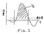
一回換気量は、図2に示す呼吸の吸気部分の間で流量を積分することで算出される。正確な値を得るためには、漏出による量、この場合tIのLI倍を減算することが必要であるが、それは、圧力が異なるので吸気と呼気との間で漏出量が異なるからである。式6はこれを記号により表わしている。
【0029】
【数5】
ピーク吸気流量
ピーク吸気は呼吸の吸気部分の間に起こる。関心があるのは患者に対する最大流量であるため、吸気漏出量を流量から減じる必要がある。
【0031】
[7] FPeak=Fmax−LI
これら3つのパラメータのためには、浄化孔漏出量の正確な推定が必要であることは明らかである。マスクを替えると浄化孔漏出量は変わるため、もはや漏出量を得ることができない。図3は、圧力の関数としてのさまざまなマスクの種類についての浄化孔漏出量(すなわち浄化孔漏出量のプロフィール)を示す。これらすべてを以下の形の放物線関数に当てはめることができることが注目されるであろう。
【0032】
LP=浄化孔漏出量=A+B*p+C*p*p
ここでA、BおよびCは定数であり、pは圧力である。なお、放物線としての関数の形は、内在的な物理的原理に基づくよりもむしろ便宜上のものである。開口部から出る流量は圧力の平方根に比例することが知られているので(ベルヌーイの式)、この形の式(すなわちLP=A√Bp)またはより高次元の多項式を用いることも可能である。
【0033】
図3を詳しく見ると、二段階またはCPAP療法に好適な現存するマスクの選択についての、浄化孔漏出流量対圧力の曲線が示される。このグラフから、これらマスクの特性に対し、典型的な圧力で、精密さを過度に失うことなく、曲線の重複(この場合図3に示す6本の太線の曲線)によって近似され得ることが明らかであろう。これら曲線の各々に対しては数学的関数(たとえば多項式)によって近似され、これら曲線の各々はルックアップ表の重複(たとえば配列)として存在し得る。したがって、これら曲線間で選択を行なうための手段を開発することが有用である。
【0034】
ガス流発生器12は、図6に示す表示装置52および操作装置50を搭載する外部パネル60を含むことが好ましい。ここで表示装置52は、典型的な二段階流れ発生器で一般に用いられる種類の4線液晶表示装置(LCD)として示されているが、どの種の従来の表示装置を用いてもよく、これにはたとえば任意の数の線、画素または解像度を有するLCD、LEDまたはCRTタイプの表示装置が含まれる。表示装置はカラーであってもモノクロームであってもよい。LCDの場合、表示装置はバックライトで照らされ得る。これに代えて表示装置52は、指またはスタイラスで画面に触れることで選択を行なうことができる種類のタッチスクリーン表示装置であってもよい。これにより、所望であれば制御パネル上の操作装置の数を減少、またはこれをなくすことができる。表示装置52は、マイクロコントローラ24から、および/または通信ポート46を通じ外部源から受け取った情報を表示できる。
【0035】
図4は、典型的な4線LCD表示装置のための好ましいメニュー構造102を示す。メニュー構造102は3つのサブメニュー構造(104a、bおよびc)からなり、これらはそれぞれ定圧(CPAP)、患者トリガ(I/E)およびアシストコントロール(A/C)の動作モードに対応する。各サブメニュー構造は主画面(106a、bまたはc)およびセットアップ画面(108a、bまたはc)を含む。I/EおよびA/Cサブメニュー構造はさらに付加的な画面(110bおよびc)を含む。主画面106a、bおよびcの各々は選択された動作モード(すなわち「CPAP」、「I/E」または「A/C」)を表示する。CPAPサブメニュー104aについての主画面106aはさらに圧力および過剰漏出量を表示する。それぞれI/EおよびA/Cサブメニュー構造104bおよび104cについての主画面106bおよび106cはさらに、1分当りの呼吸頻度、ピーク圧力、一回換気量、および過剰漏出量を表示する。セットアップ画面108a、bおよびcの各々は、選択された浄化孔漏出量のプロフィール(たとえば1、2、3、4、5または6)を表示し、さらに他のパラメータ、たとえばすべてのモードについての遅延、傾斜および開始圧力、ならびにI/EおよびA/CモードについてのIPEPおよびEPAP圧力などを表示する。
【0036】
図6を再び参照すると、流れ発生器12はボタンまたはキーの形のさまざまな操作装置50を含むことを見て取ることができる。オペレータはこれら操作装置を用い、表示装置52で表示されるメニュー構造を通じて操縦し、特定のマスクについての浄化孔漏出量のプロフィールなどのさまざまなパラメータを選択することができる。図6を左から右に見ると、操作装置はモードキー50a、設定またはセットアップキー50b、下方向矢印キー50c、および上方向矢印キー50dを含む。モードキー50aを押すと、動作のモード(すなわちCPAP、I/EまたはA/C)が選択される。表示装置52は、選択された動作モードに対応する主画面を表示する。図5のフローチャートも参照して、202で示すように、設定キー50bを押すとシステムはセットアップまたは設定モードに置かれ、適当な組のセットアップ画面(108a、bまたはc)が表示される。204で示すように、現在の設定がセットアップ画面で表示される。MASK Lと名付けられた設定モードの最後の項目では、使用者は上方向および下方向の矢印キー50dおよび50cを用いて1から6までの値を選択することができる。メモリに記憶された値が最初に表示される。これは次に、206で示すように、矢印キーを用いて新たな値を選択することで変更可能であり、この時点でこれは208で示すように再びメモリ(プログラムメモリまたはデータ記憶装置44)で記憶され、210で示すように使用者は設定モードから出ることができ、この後、212で示すように過剰漏出量、一回換気量およびピーク流量の算出において数字の項目に関連付けられた機能が用いられ、装置52上で表示される。次に、表示装置を見ながらマスクを適合させ、過剰漏出値が最小になるまで作業を行なうことによって、マスクの適合を最適化することができる。
【0037】
これに代えて、プログラムメモリまたはデータ記憶装置44は、標準的なRS232シリアル通信ポートなどの外部通信ポート46経由で遠隔アクセスされ得ることも予想されている。適当な通信ソフトウェアを有する遠隔コンピュータを用いて、さまざまな形式でコンピュータの画面上に浄化孔の漏出量のプロフィールの設定が表示され得る。図7は、この発明に従うガス流発生器に関連した設定を表示するための形式300を例示する。図7はさらに、コンピュータの画面上に表示された典型的なスライダ操作部302を用いてどのようにマスク漏出量を設定できるかについての例を示す。これに代えて設定手段としては、他のパラメータと用いられるものに類似のテキストボックス操作部304を用いることもできる。
【0038】
以上より、マスクの種類を替えた際、標準漏出量をすばやく選択して都合よく変化させることによって、一回換気量、ピーク流量および過剰漏出量の正確な推定値を入手できることが理解されるであろう。
【0039】
以上、この発明を詳細に説明したが、この発明は記載した特定の実施例に限定されることを意図していない。当業者であればこの発明の概念から離れることなく、ここに記載された特定の実施例について数多くの用途および変形、ならびにこれからの離脱が可能であることは明らかである。たとえば、6つの浄化孔漏出量のプロフィールが例示されているが、多項式またはルックアップ表の値として任意の数のプロフィールを記憶させることもできると理解されるであろう。さらに、追加のプロフィールがメモリ内にプログラムされ得ること、および/またはメモリに記憶されたプロフィールを編集することも、この発明の範囲内である。プロフィールのプログラミングまたは編集は、通信ポートを介してガス流発生器に接続された外部コンピュータを用いて達成され得る。プロフィールは、外部コンピュータに記憶させても、またはガス流発生器内に収められたメモリにプログラムしてもよい。メニュー構造は、ここに示した以外のフィールドを含むように、および/または使用者の要求に依存して或るフィールドを削除するように変形され得る。さらに、ここに示した操作装置は、モード、浄化孔漏出量のプロフィールなどを選択するのに用いられ得る操作装置の種類を単に例示するためのものである。その他の種類の操作装置、たとえばプッシュボタン、スイッチ、ノブ、キーパッド、およびタッチスクリーンを用いることも可能である。所望であれば、特定の機能またはパラメータのうち2つ以上を選択するのに単一の操作装置を用いることもできる。過剰漏出量、ピーク流量および一回換気量について算出された値がマイクロコントローラにより用いられて、ガス流発生器の動作パラメータを変化させることができる。
【図面の簡単な説明】
【図1】この発明に従う流れ発生装置を含む、使用者に対して呼吸ガスを送出するための装置を概略的に示す図である。
【図2】呼吸の吸気部分についての流量対時間の曲線を積分することによる一回換気量の算出を示す図である。
【図3】さまざまなマスクの種類についての漏出流量対圧力の曲線(細線)と、合成平均曲線(太線)とを示す図である。
【図4】4線×16文字のLCD表示装置のメニュー構造を示す図であり、ここで、MASK Lと名付けられた表示装置の最後の行では、多数のマスク漏出量が設定可能である。
【図5】この発明の本質を構成するブロック図である。
【図6】典型的な装置のキーパッドおよび画面を示す図である。
【図7】外部通信プログラムを用いてどのようにマスク漏出量設定が設定され得るかを示す図である。[0001]
BACKGROUND OF THE INVENTION
FIELD OF THE INVENTION The present invention relates generally to devices for delivering respiratory gas to a patient, and more particularly to a gas flow generator having a standard manual leak control.
[0002]
Description of the Background Art Sleep apnea syndrome affects approximately 1% to 5% of the general population, due to upper airway obstruction during sleep. Sleep is fragmented, ventilation is partially stopped, and desaturation of oxidized hemoglobin occurs as a direct result of sleep apnea. These in turn lead to daytime somnolence, arrhythmias, congestive heart failure, and various other health and cognitive dysfunctions. All of these have secondary social and behavioral consequences that not only increase the patient's chances of getting sick, but also engage the patient in activities that require concentration (such as driving a car). The risk of death may also increase.
[0003]
The causes of upper airway obstruction can vary, but include anatomical changes that lead to narrow passageways, loss of muscle tone, and / or reduced tissue weight. Age and obesity are considered risk factors, suggesting that excess soft tissue in the neck may exert enough pressure on internal tissues to impair airway patency.
[0004]
The procedure involves a variety of surgical interventions, including palatopharyngoplasty, gastric surgery for obesity, maxillofacial reconstruction, or even tracheostomy. All of these treatments carry a great risk of causing the disease. A less harmful treatment that requires some behavioral adaptation is nasal continuous positive airway pressure (nCPAP or simply CPAP). In its simplest form, this procedure involves applying a positive pressure to the airway using an airflow generator to keep the passage open. If used consistently during sleep, it is possible to alleviate the symptoms of sleep apnea.
[0005]
However, due to its continuous nature, some patients do not respond or are non-compliant with CPAP treatment. This is especially true if the CPAP prescription pressure is relatively high. For such individuals, a two-stage therapy is a more reasonable option. Pressure circulates from high (IPAP) to low (EPAP) during inspiration to promote exhalation while continuing to provide some nominal pressure support. In addition, two-stage therapy is also beneficial for people who have some form of impaired breathing, such as diaphragmatic weakness or spinal injury from disease, where continuous pressure can be a problem.
[0006]
Whether the invasive flow generator provides pressure in one stage (CPAP), two stages (two-stage / BiPAP) or multiple stages, all are of a certain type. Use an interface (typically a mask) with a patient with a standard leak. The purpose of a standard leak is to get carbon dioxide out of the system to minimize rebreathing. Otherwise, a significant tidal volume would be required to clean the dead space in the hose and mask. A standard leak is the result of a purification hole of a given size (sometimes called an exhaust or bleed) or a number of smaller holes. The size of these holes is determined by the supply capacity of the generator and the desired mask characteristics.
[0007]
When using a flow generator in a home environment, feedback to the user may be minimal. However, in a hospital environment or sleep laboratory, it is desirable to be aware of various measurable characteristics of a user's breathing pattern. Typically, these include respiratory frequency, inspiration time to expiration time ratio (I: E ratio), leakage above standard pore clearance, tidal volume, and peak expiratory flow. In particular, for the last three parameters, it is essential to know the purification hole leakage amount for accurate calculation.
[0008]
Various methods have been used to calculate leakage. For example, Estes et al. (U.S. Pat. No. 5,901,704) disclose a method of calculating total leakage and adjusting the flow to compensate for each breath. However, there is no discussion of how standard pores affect tidal volume, excess leakage or peak flow calculations, and how to select multiple standard pores. Has not been discussed.
[0009]
Another approach uses a look-up table that is appropriate for a single type of mask. For example, the KS335 gas flow generator sold by Puritan Benett includes a look-up table for leaks in liters per second, which is indexed at set pressure. The look-up table is based on a standard 4 mm hole in the mask. Masks with purifying holes other than 4 mm do not provide accurate readings for the device.
[0010]
Other manufacturers provide certain automatic titration means or procedures, such as those described in Brewer et al. (WO 00/037135). Here, a special “mask adaptation” in which the apparatus is set to a specific mask adaptation test pressure is described, and an “average flow rate” obtained as a result of low-pass filtering the air flow rate is obtained. This test pressure can then be stepped over the pressure range of interest and the results stored. This procedure will be repeated if the mask is changed.
[0011]
In other methods, such as the method disclosed by Berthon Jones (WO 98/06449), dividing the average flow rate by the square root of the instantaneous measured pressure provides a non-linear conduction through the mask opening. Estimate the rate. Although this method is versatile, it is not accurate because it must estimate the amount of purification hole leakage.
[0012]
Summary of the Invention
According to one aspect of the present invention, there is provided an apparatus for delivering breathing gas to a patient, the apparatus sensing a blower for generating a flow of breathing gas and a flow rate of the breathing gas generated by the blower. Device comprising a gas flow sensor arranged in a manner as described above, a plurality of purging hole leakage profiles corresponding to a particular type of respiratory mask, and one of the plurality of purifying hole leaking profiles from the memory device. Means for selecting an over-leak rate, a tidal volume using the flow rate measured by the gas flow sensor and the selected purging hole leak rate profile. , And at least one of the peak flows.
[0013]
According to another aspect of the present invention, there is provided a method for delivering breathing gas to a user, the method comprising the steps of generating a flow of breathing gas using a gas flow generator; Measuring the flow rate, selecting one of the plurality of purification hole leakage profiles from the memory device, and using the measured flow rate and the selected purification hole leakage profile to determine excess leakage, Calculating at least one of a tidal volume and a peak flow rate.
[0014]
In a preferred embodiment, the invention includes display means, selection means, and storage means, wherein different curves for pressure versus leak rate are provided for the purpose of calculating a standard leak rate appropriate for a given mask type. Can be selected. Thus, it is possible to conveniently calculate accurate values for the tidal volume, the excessive leak rate, and the peak flow rate. The fit of the mask can be modified based on the displayed excess leak value.
[0015]
The above and other features and advantages of the present invention will be better understood from a reading of the following description of a preferred embodiment of the invention in connection with the accompanying drawings. In the drawings, like reference numbers indicate like parts.
[0016]
DETAILED DESCRIPTION OF THE PREFERRED EMBODIMENTS
An
[0017]
The
[0018]
The
[0019]
Typically, the amount of leakage is calculated by averaging the flow during a single breath including the inspiratory and expiratory phases (Equation 1). Specifically, the total leak (L T ) is the sum of the instantaneous flow rates divided by the sum of the time intervals between flow measurements. At low pressures, the flow rate (into the device when exhaling) may be negative, so it is important that the flow converter is bidirectional.
[0020]
(Equation 1)
The total leakage consists of excess leakage (L Ex ) and purification hole leakage (L P ). Over-leakage is a leak that exceeds the clarification hole leakage and is generally caused by a poor mask fit. Knowing the amount of this leakage is beneficial, so that the mask can be adjusted to minimize its value. Therefore, instead of L Ex of L T in many devices is displayed. L Ex is calculated by simply rearranging Equation 2 and subtracting L P from L T.
[0022]
[2] L T = L Ex + L P
The total amount of leakage is easily calculated, and, as long as L P is a function of the pressure when the type of the mask is known, be relatively easy to calculate the L Ex in CPAP device generating a pressure at a constant level Can be. In a two-stage device, L P at every moment will be calculated for the pressure value at that moment. The sum of the difference between the standard flow rate and the purifier flow rate summed over the entire breath is the excess leak (Equation 3).
[0023]
(Equation 2)
For an approximate square wave,
[0025]
[Equation 3]
If closer the pressure waveform into a square wave, a total leakage of the intake leak portion (L I) and expiratory leak portion (L E) and subdividing it is possible to (Equation 4), each intake time (t I) and Exists for expiration time (t E ). Both L I and L E has a cleaning hole leak portion and an excess leak portion. For L I or L E, they can be solved assuming to have the same ratio as the cleaning hole leakage amount (Equation 5), the value of the purification hole leakage amount is known a priori as a function of pressure.
[0027]
(Equation 4)
Calculation of tidal volume The tidal volume is calculated by integrating the flow rate during the inspiratory portion of the respiration shown in FIG. In order to obtain an accurate value, the amount by leakage, it is necessary to subtract L I times in this case t I, it is because leakage of between inspiration and expiration so that different pressures are different is there. Equation 6 illustrates this symbolically.
[0029]
(Equation 5)
Peak inspiratory flow Peak inspiration occurs during the inspiratory portion of breathing. Since we are interested in the maximum flow to the patient, the inspiratory leakage needs to be subtracted from the flow.
[0031]
[7] F Peak = F max -L I
Obviously, for these three parameters, an accurate estimation of purification hole leakage is required. When the mask is changed, the leakage amount of the purification hole changes, so that the leakage amount can no longer be obtained. FIG. 3 shows purging hole leakage (ie, purging hole leakage profile) for various mask types as a function of pressure. It will be noted that all of these can be applied to a parabolic function of the form
[0032]
L P = purified hole leakage amount = A + B * p + C * p * p
Where A, B and C are constants and p is pressure. Note that the shape of the function as a parabola is for convenience rather than based on intrinsic physical principles. Since it is known that the flow out of the opening is proportional to the square root of the pressure (Bernoulli equation), it is also possible to use an equation of this form (ie L P = ALBp) or a higher dimensional polynomial. is there.
[0033]
Looking closely at FIG. 3, there is shown a purge hole leak rate versus pressure curve for selection of an existing mask suitable for two-stage or CPAP therapy. It is clear from the graph that the properties of these masks can be approximated by the overlap of the curves (in this case the six bold curves shown in FIG. 3) at typical pressure and without undue loss of precision. Will. Each of these curves is approximated by a mathematical function (eg, a polynomial), and each of these curves may exist as an overlap (eg, an array) of the look-up table. Therefore, it is useful to develop a means for making a selection between these curves.
[0034]
The
[0035]
FIG. 4 shows a
[0036]
Referring again to FIG. 6, it can be seen that the
[0037]
Alternatively, it is envisioned that the program memory or data storage device 44 may be remotely accessed via an
[0038]
From the above, it can be understood that when changing the type of mask, it is possible to obtain an accurate estimate of the tidal volume, the peak flow rate and the excess leak rate by quickly selecting and conveniently changing the standard leak rate. There will be.
[0039]
While the invention has been described in detail, the invention is not intended to be limited to the particular embodiments described. It will be apparent to those skilled in the art that many uses and variations and departures from the specific embodiments described herein are possible without departing from the inventive concept. For example, while six through-hole leakage profiles are illustrated, it will be understood that any number of profiles may be stored as polynomial or look-up table values. Further, it is within the scope of the invention that additional profiles can be programmed into the memory and / or to edit profiles stored in the memory. Programming or editing the profile can be accomplished using an external computer connected to the gas flow generator via a communication port. The profile may be stored on an external computer or programmed into a memory contained within the gas flow generator. The menu structure may be modified to include fields other than those shown here and / or to delete certain fields depending on user requirements. Further, the operating devices shown herein are merely illustrative of the types of operating devices that may be used to select modes, purging hole leakage profiles, and the like. Other types of operating devices can be used, such as push buttons, switches, knobs, keypads, and touch screens. If desired, a single operating device may be used to select more than one of a particular function or parameter. The values calculated for excess leakage, peak flow and tidal volume can be used by the microcontroller to change the operating parameters of the gas flow generator.
[Brief description of the drawings]
FIG. 1 schematically shows a device for delivering respiratory gas to a user, including a flow generating device according to the invention.
FIG. 2 illustrates the calculation of tidal volume by integrating a flow versus time curve for the inspiratory portion of breathing.
FIG. 3 shows a leakage flow versus pressure curve (thin line) and a combined average curve (thick line) for various mask types.
FIG. 4 is a diagram showing a menu structure of a 4-line × 16-character LCD display device, where a large number of mask leakage amounts can be set in the last line of the display device named MASK L.
FIG. 5 is a block diagram showing the essence of the present invention.
FIG. 6 illustrates a keypad and screen of a typical device.
FIG. 7 is a diagram showing how a mask leakage amount setting can be set using an external communication program.
Claims (20)
呼吸ガスの流れを発生する送風機と、
前記送風機が発生した呼吸ガスの流れを検知するように配置されたガス流量センサと、
特定の種類の呼吸器具に対応する複数の浄化孔漏出量のプロフィールを含むメモリ装置と、
前記メモリ装置から前記複数の浄化孔漏出量のプロフィールのうち1つを選択するための手段と、
マイクロプロセッサとを含み、前記マイクロプロセッサは、前記ガス流量センサにより測定された流量と、選択された浄化孔漏出量のプロフィールとを用いて、過剰漏出量、一回換気量およびピーク流量のうち少なくとも1つを算出するようにプログラムされる、装置。A device for delivering breathing gas to a patient,
A blower for generating a flow of breathing gas;
A gas flow sensor arranged to detect the flow of breathing gas generated by the blower,
A memory device including a plurality of purging hole leak rate profiles corresponding to a particular type of respiratory device;
Means for selecting one of the plurality of purification hole leak rate profiles from the memory device;
A microprocessor using the flow rate measured by the gas flow rate sensor and the selected purification hole leak rate profile to determine at least one of excess leak rate, tidal volume, and peak flow rate. An apparatus that is programmed to calculate one.
ガス流発生器を用いて呼吸ガスの流れを発生させるステップと、
呼吸ガスの流量を測定するステップと、
メモリ装置からの複数の浄化孔漏出量のプロフィールのうち1つを選択するステップと、
測定された流量と選択された浄化孔漏出量のプロフィールとを用いて過剰漏出量、一回換気量およびピーク流量のうち少なくとも1つを算出するステップとを含む、方法。A method for delivering breathing gas to a user,
Generating a flow of breathing gas using a gas flow generator;
Measuring the flow of breathing gas;
Selecting one of a plurality of purification hole leakage profiles from the memory device;
Calculating at least one of excess leakage, tidal volume and peak flow using the measured flow rate and the selected porosity leak rate profile.
Applications Claiming Priority (2)
| Application Number | Priority Date | Filing Date | Title |
|---|---|---|---|
| US09/672,955 US6546930B1 (en) | 2000-09-29 | 2000-09-29 | Bi-level flow generator with manual standard leak adjustment |
| PCT/US2001/030456 WO2002026304A2 (en) | 2000-09-29 | 2001-09-28 | Bi-level flow generator |
Publications (1)
| Publication Number | Publication Date |
|---|---|
| JP2004509710A true JP2004509710A (en) | 2004-04-02 |
Family
ID=24700721
Family Applications (1)
| Application Number | Title | Priority Date | Filing Date |
|---|---|---|---|
| JP2002530133A Withdrawn JP2004509710A (en) | 2000-09-29 | 2001-09-28 | Two-stage flow generator with manual standard leak control |
Country Status (8)
| Country | Link |
|---|---|
| US (1) | US6546930B1 (en) |
| EP (1) | EP1322368B1 (en) |
| JP (1) | JP2004509710A (en) |
| AT (1) | ATE372141T1 (en) |
| CA (1) | CA2423184C (en) |
| DE (1) | DE60130349T2 (en) |
| ES (1) | ES2292630T3 (en) |
| WO (1) | WO2002026304A2 (en) |
Cited By (4)
| Publication number | Priority date | Publication date | Assignee | Title |
|---|---|---|---|---|
| JP2010501290A (en) * | 2006-08-30 | 2010-01-21 | レスメド・リミテッド | Determination of leakage during CPAP treatment |
| JP2011502615A (en) * | 2007-11-13 | 2011-01-27 | アイエムティ インフォメーション マネージメント テクノロジー アーゲー | Artificial respiration and / or anesthesia equipment |
| JP2011516159A (en) * | 2008-03-31 | 2011-05-26 | ネルコア・ピユーリタン・ベネツト・エル・エル・シー | Ventilator leak compensation |
| JP2014050519A (en) * | 2012-09-06 | 2014-03-20 | Nidec Copal Electronics Corp | Cpap device |
Families Citing this family (140)
| Publication number | Priority date | Publication date | Assignee | Title |
|---|---|---|---|---|
| US5490502A (en) * | 1992-05-07 | 1996-02-13 | New York University | Method and apparatus for optimizing the continuous positive airway pressure for treating obstructive sleep apnea |
| US6866040B1 (en) * | 1994-09-12 | 2005-03-15 | Nellcor Puritan Bennett France Developpement | Pressure-controlled breathing aid |
| US6024089A (en) | 1997-03-14 | 2000-02-15 | Nelcor Puritan Bennett Incorporated | System and method for setting and displaying ventilator alarms |
| FR2789593B1 (en) * | 1999-05-21 | 2008-08-22 | Mallinckrodt Dev France | APPARATUS FOR SUPPLYING AIR PRESSURE TO A PATIENT WITH SLEEP DISORDERS AND METHODS OF CONTROLLING THE SAME |
| DE20022730U1 (en) | 1999-08-05 | 2002-11-21 | Map Medizin Technologie Gmbh | Device for supplying a breathing gas, humidification device, breathing gas hose and connection device therefor |
| DE10161057A1 (en) * | 2001-12-12 | 2003-07-10 | Heptec Gmbh | Process for controlling the differential pressure in a CPAP device and CPAP device |
| NZ544109A (en) * | 2003-06-18 | 2008-04-30 | Resmed Ltd | Method and apparatus for monitoring bariatric parameters and sleep disordered breathing |
| AU2003903139A0 (en) * | 2003-06-20 | 2003-07-03 | Resmed Limited | Breathable gas apparatus with humidifier |
| CA2753378C (en) | 2003-06-20 | 2016-01-19 | Resmed Limited | Breathable gas apparatus with humidifier |
| FR2858236B1 (en) | 2003-07-29 | 2006-04-28 | Airox | DEVICE AND METHOD FOR SUPPLYING RESPIRATORY GAS IN PRESSURE OR VOLUME |
| NZ547601A (en) * | 2003-12-29 | 2008-06-30 | Resmed Ltd | Mechanical ventilation in the presence of sleep disordered breathing |
| US8910632B2 (en) * | 2004-07-08 | 2014-12-16 | Breas Medical, Ab | Energy trigger |
| FR2875138B1 (en) * | 2004-09-15 | 2008-07-11 | Mallinckrodt Dev France Sa | CONTROL METHOD FOR A HEATING HUMIDIFIER |
| WO2006092001A1 (en) | 2005-03-01 | 2006-09-08 | Resmed Limited | Recognition system for an apparatus that delivers breathable gas to a patient |
| US7798144B2 (en) | 2005-07-29 | 2010-09-21 | Resmed Limited | Life style flow generator and mask system |
| US8424514B2 (en) * | 2005-10-14 | 2013-04-23 | Resmed Limited | Flow generator message system |
| US8021310B2 (en) | 2006-04-21 | 2011-09-20 | Nellcor Puritan Bennett Llc | Work of breathing display for a ventilation system |
| EP2032192A4 (en) * | 2006-06-05 | 2014-02-19 | Resmed Ltd | Systems and/or methods for calibration-less devices or less expensive calibration devices for treating sleep-disordered breathing |
| US7784461B2 (en) | 2006-09-26 | 2010-08-31 | Nellcor Puritan Bennett Llc | Three-dimensional waveform display for a breathing assistance system |
| US8902568B2 (en) | 2006-09-27 | 2014-12-02 | Covidien Lp | Power supply interface system for a breathing assistance system |
| US20080078390A1 (en) * | 2006-09-29 | 2008-04-03 | Nellcor Puritan Bennett Incorporated | Providing predetermined groups of trending parameters for display in a breathing assistance system |
| US20090165795A1 (en) * | 2007-12-31 | 2009-07-02 | Nellcor Puritan Bennett Llc | Method and apparatus for respiratory therapy |
| US20090205663A1 (en) * | 2008-02-19 | 2009-08-20 | Nellcor Puritan Bennett Llc | Configuring the operation of an alternating pressure ventilation mode |
| US20090205661A1 (en) * | 2008-02-20 | 2009-08-20 | Nellcor Puritan Bennett Llc | Systems and methods for extended volume range ventilation |
| US20090241956A1 (en) * | 2008-03-27 | 2009-10-01 | Nellcor Puritan Bennett Llc | Method for controlling delivery of breathing gas to a patient using multiple ventilation parameters |
| WO2009120639A2 (en) | 2008-03-27 | 2009-10-01 | Nellcor Puritan Bennett Llc | Breathing assistance systems with lung recruitment maneuvers |
| US10207069B2 (en) | 2008-03-31 | 2019-02-19 | Covidien Lp | System and method for determining ventilator leakage during stable periods within a breath |
| US8746248B2 (en) | 2008-03-31 | 2014-06-10 | Covidien Lp | Determination of patient circuit disconnect in leak-compensated ventilatory support |
| US8792949B2 (en) * | 2008-03-31 | 2014-07-29 | Covidien Lp | Reducing nuisance alarms |
| US8425428B2 (en) * | 2008-03-31 | 2013-04-23 | Covidien Lp | Nitric oxide measurements in patients using flowfeedback |
| US8267085B2 (en) | 2009-03-20 | 2012-09-18 | Nellcor Puritan Bennett Llc | Leak-compensated proportional assist ventilation |
| US8485185B2 (en) | 2008-06-06 | 2013-07-16 | Covidien Lp | Systems and methods for ventilation in proportion to patient effort |
| WO2010028148A1 (en) * | 2008-09-04 | 2010-03-11 | Nellcor Puritan Bennett Llc | Inverse sawtooth pressure wave train purging in medical ventilators |
| US8551006B2 (en) | 2008-09-17 | 2013-10-08 | Covidien Lp | Method for determining hemodynamic effects |
| DE102008048824A1 (en) * | 2008-09-22 | 2010-03-25 | Borm, Hans-Jürgen | Method and device for the automatic determination of a ventilation volume in mechanical ventilation, taking into account leaks |
| US8424520B2 (en) * | 2008-09-23 | 2013-04-23 | Covidien Lp | Safe standby mode for ventilator |
| US8794234B2 (en) | 2008-09-25 | 2014-08-05 | Covidien Lp | Inversion-based feed-forward compensation of inspiratory trigger dynamics in medical ventilators |
| US8181648B2 (en) | 2008-09-26 | 2012-05-22 | Nellcor Puritan Bennett Llc | Systems and methods for managing pressure in a breathing assistance system |
| US8302602B2 (en) | 2008-09-30 | 2012-11-06 | Nellcor Puritan Bennett Llc | Breathing assistance system with multiple pressure sensors |
| US8585412B2 (en) * | 2008-09-30 | 2013-11-19 | Covidien Lp | Configurable respiratory muscle pressure generator |
| US8439032B2 (en) * | 2008-09-30 | 2013-05-14 | Covidien Lp | Wireless communications for a breathing assistance system |
| US8652064B2 (en) | 2008-09-30 | 2014-02-18 | Covidien Lp | Sampling circuit for measuring analytes |
| US8393323B2 (en) | 2008-09-30 | 2013-03-12 | Covidien Lp | Supplemental gas safety system for a breathing assistance system |
| US8302600B2 (en) | 2008-09-30 | 2012-11-06 | Nellcor Puritan Bennett Llc | Battery management for a breathing assistance system |
| WO2010085895A2 (en) * | 2009-01-29 | 2010-08-05 | Yrt Limited | A method for estimating leaks from ventilator circuits |
| US8424521B2 (en) | 2009-02-27 | 2013-04-23 | Covidien Lp | Leak-compensated respiratory mechanics estimation in medical ventilators |
| US8434479B2 (en) | 2009-02-27 | 2013-05-07 | Covidien Lp | Flow rate compensation for transient thermal response of hot-wire anemometers |
| US20100218766A1 (en) * | 2009-02-27 | 2010-09-02 | Nellcor Puritan Bennett Llc | Customizable mandatory/spontaneous closed loop mode selection |
| US8418691B2 (en) | 2009-03-20 | 2013-04-16 | Covidien Lp | Leak-compensated pressure regulated volume control ventilation |
| US9186075B2 (en) * | 2009-03-24 | 2015-11-17 | Covidien Lp | Indicating the accuracy of a physiological parameter |
| US8776790B2 (en) * | 2009-07-16 | 2014-07-15 | Covidien Lp | Wireless, gas flow-powered sensor system for a breathing assistance system |
| US20110023878A1 (en) * | 2009-07-31 | 2011-02-03 | Nellcor Puritan Bennett Llc | Method And System For Delivering A Single-Breath, Low Flow Recruitment Maneuver |
| US8789529B2 (en) | 2009-08-20 | 2014-07-29 | Covidien Lp | Method for ventilation |
| US11110246B2 (en) | 2009-10-09 | 2021-09-07 | Fisher & Paykel Healthcare Limited | Breathing assistance apparatus |
| US8439037B2 (en) * | 2009-12-01 | 2013-05-14 | Covidien Lp | Exhalation valve assembly with integrated filter and flow sensor |
| US8439036B2 (en) | 2009-12-01 | 2013-05-14 | Covidien Lp | Exhalation valve assembly with integral flow sensor |
| US8469030B2 (en) | 2009-12-01 | 2013-06-25 | Covidien Lp | Exhalation valve assembly with selectable contagious/non-contagious latch |
| US8469031B2 (en) | 2009-12-01 | 2013-06-25 | Covidien Lp | Exhalation valve assembly with integrated filter |
| US8421465B2 (en) * | 2009-12-02 | 2013-04-16 | Covidien Lp | Method and apparatus for indicating battery cell status on a battery pack assembly used during mechanical ventilation |
| US8434484B2 (en) * | 2009-12-03 | 2013-05-07 | Covidien Lp | Ventilator Respiratory Variable-Sized Gas Accumulator |
| US9119925B2 (en) | 2009-12-04 | 2015-09-01 | Covidien Lp | Quick initiation of respiratory support via a ventilator user interface |
| US20110132369A1 (en) * | 2009-12-04 | 2011-06-09 | Nellcor Puritan Bennett Llc | Ventilation System With System Status Display |
| US20110138311A1 (en) * | 2009-12-04 | 2011-06-09 | Nellcor Puritan Bennett Llc | Display Of Respiratory Data On A Ventilator Graphical User Interface |
| US8482415B2 (en) * | 2009-12-04 | 2013-07-09 | Covidien Lp | Interactive multilevel alarm |
| US8924878B2 (en) | 2009-12-04 | 2014-12-30 | Covidien Lp | Display and access to settings on a ventilator graphical user interface |
| US9262588B2 (en) | 2009-12-18 | 2016-02-16 | Covidien Lp | Display of respiratory data graphs on a ventilator graphical user interface |
| US8499252B2 (en) | 2009-12-18 | 2013-07-30 | Covidien Lp | Display of respiratory data graphs on a ventilator graphical user interface |
| US20110146681A1 (en) * | 2009-12-21 | 2011-06-23 | Nellcor Puritan Bennett Llc | Adaptive Flow Sensor Model |
| EP2515979B1 (en) * | 2009-12-21 | 2016-05-04 | Koninklijke Philips N.V. | Automatic identification of a patient interface device in a pressure support system |
| US20110146683A1 (en) * | 2009-12-21 | 2011-06-23 | Nellcor Puritan Bennett Llc | Sensor Model |
| US8400290B2 (en) | 2010-01-19 | 2013-03-19 | Covidien Lp | Nuisance alarm reduction method for therapeutic parameters |
| US8707952B2 (en) * | 2010-02-10 | 2014-04-29 | Covidien Lp | Leak determination in a breathing assistance system |
| US20110209702A1 (en) * | 2010-02-26 | 2011-09-01 | Nellcor Puritan Bennett Llc | Proportional Solenoid Valve For Low Molecular Weight Gas Mixtures |
| US9302061B2 (en) | 2010-02-26 | 2016-04-05 | Covidien Lp | Event-based delay detection and control of networked systems in medical ventilation |
| US8539949B2 (en) | 2010-04-27 | 2013-09-24 | Covidien Lp | Ventilation system with a two-point perspective view |
| US8453643B2 (en) | 2010-04-27 | 2013-06-04 | Covidien Lp | Ventilation system with system status display for configuration and program information |
| US8511306B2 (en) | 2010-04-27 | 2013-08-20 | Covidien Lp | Ventilation system with system status display for maintenance and service information |
| US8638200B2 (en) | 2010-05-07 | 2014-01-28 | Covidien Lp | Ventilator-initiated prompt regarding Auto-PEEP detection during volume ventilation of non-triggering patient |
| US8607788B2 (en) | 2010-06-30 | 2013-12-17 | Covidien Lp | Ventilator-initiated prompt regarding auto-PEEP detection during volume ventilation of triggering patient exhibiting obstructive component |
| US8607791B2 (en) | 2010-06-30 | 2013-12-17 | Covidien Lp | Ventilator-initiated prompt regarding auto-PEEP detection during pressure ventilation |
| US8607790B2 (en) | 2010-06-30 | 2013-12-17 | Covidien Lp | Ventilator-initiated prompt regarding auto-PEEP detection during pressure ventilation of patient exhibiting obstructive component |
| US8607789B2 (en) | 2010-06-30 | 2013-12-17 | Covidien Lp | Ventilator-initiated prompt regarding auto-PEEP detection during volume ventilation of non-triggering patient exhibiting obstructive component |
| US8676285B2 (en) | 2010-07-28 | 2014-03-18 | Covidien Lp | Methods for validating patient identity |
| EP2598192B1 (en) * | 2010-07-30 | 2018-04-04 | ResMed Limited | Methods and devices with leak detection |
| US8554298B2 (en) | 2010-09-21 | 2013-10-08 | Cividien LP | Medical ventilator with integrated oximeter data |
| EP2632521B1 (en) * | 2010-10-26 | 2017-06-14 | Koninklijke Philips N.V. | Pressure line purging system for a mechanical ventilator |
| US8595639B2 (en) | 2010-11-29 | 2013-11-26 | Covidien Lp | Ventilator-initiated prompt regarding detection of fluctuations in resistance |
| US8757153B2 (en) | 2010-11-29 | 2014-06-24 | Covidien Lp | Ventilator-initiated prompt regarding detection of double triggering during ventilation |
| US8757152B2 (en) | 2010-11-29 | 2014-06-24 | Covidien Lp | Ventilator-initiated prompt regarding detection of double triggering during a volume-control breath type |
| US8676529B2 (en) | 2011-01-31 | 2014-03-18 | Covidien Lp | Systems and methods for simulation and software testing |
| US8788236B2 (en) | 2011-01-31 | 2014-07-22 | Covidien Lp | Systems and methods for medical device testing |
| US8783250B2 (en) | 2011-02-27 | 2014-07-22 | Covidien Lp | Methods and systems for transitory ventilation support |
| US9038633B2 (en) | 2011-03-02 | 2015-05-26 | Covidien Lp | Ventilator-initiated prompt regarding high delivered tidal volume |
| US8714154B2 (en) | 2011-03-30 | 2014-05-06 | Covidien Lp | Systems and methods for automatic adjustment of ventilator settings |
| US9629971B2 (en) | 2011-04-29 | 2017-04-25 | Covidien Lp | Methods and systems for exhalation control and trajectory optimization |
| US8776792B2 (en) | 2011-04-29 | 2014-07-15 | Covidien Lp | Methods and systems for volume-targeted minimum pressure-control ventilation |
| US9089657B2 (en) | 2011-10-31 | 2015-07-28 | Covidien Lp | Methods and systems for gating user initiated increases in oxygen concentration during ventilation |
| US9364624B2 (en) | 2011-12-07 | 2016-06-14 | Covidien Lp | Methods and systems for adaptive base flow |
| US9498589B2 (en) | 2011-12-31 | 2016-11-22 | Covidien Lp | Methods and systems for adaptive base flow and leak compensation |
| US9022031B2 (en) | 2012-01-31 | 2015-05-05 | Covidien Lp | Using estimated carinal pressure for feedback control of carinal pressure during ventilation |
| US9327089B2 (en) | 2012-03-30 | 2016-05-03 | Covidien Lp | Methods and systems for compensation of tubing related loss effects |
| US8844526B2 (en) | 2012-03-30 | 2014-09-30 | Covidien Lp | Methods and systems for triggering with unknown base flow |
| US8985108B2 (en) * | 2012-04-06 | 2015-03-24 | Breathe Technologies, Inc. | Mechanical ventilation mask fit status indication |
| US9993604B2 (en) | 2012-04-27 | 2018-06-12 | Covidien Lp | Methods and systems for an optimized proportional assist ventilation |
| US9144658B2 (en) | 2012-04-30 | 2015-09-29 | Covidien Lp | Minimizing imposed expiratory resistance of mechanical ventilator by optimizing exhalation valve control |
| NZ630525A (en) * | 2012-05-02 | 2016-06-24 | Resmed Ltd | Methods and apparatus for pressure treatment modulation |
| US9872965B2 (en) * | 2012-06-15 | 2018-01-23 | Breathe Technologies, Inc. | Method and system for operating a patient ventilation device |
| US10362967B2 (en) | 2012-07-09 | 2019-07-30 | Covidien Lp | Systems and methods for missed breath detection and indication |
| US9027552B2 (en) | 2012-07-31 | 2015-05-12 | Covidien Lp | Ventilator-initiated prompt or setting regarding detection of asynchrony during ventilation |
| EP3851144B1 (en) * | 2012-09-12 | 2024-03-13 | Maquet Critical Care AB | Volume reflector status indicator for anesthesia system |
| US9375542B2 (en) | 2012-11-08 | 2016-06-28 | Covidien Lp | Systems and methods for monitoring, managing, and/or preventing fatigue during ventilation |
| US20140150796A1 (en) * | 2012-11-30 | 2014-06-05 | Covidien Lp | System and method for detecting minimal ventilation support with proportional assist ventilation plus software and remote monitoring |
| US9289573B2 (en) | 2012-12-28 | 2016-03-22 | Covidien Lp | Ventilator pressure oscillation filter |
| US20140190485A1 (en) * | 2013-01-10 | 2014-07-10 | Covidien Lp | System and method for detecting minimal ventilation support with volume ventilation plus software and remote monitoring |
| US9492629B2 (en) | 2013-02-14 | 2016-11-15 | Covidien Lp | Methods and systems for ventilation with unknown exhalation flow and exhalation pressure |
| USD731049S1 (en) | 2013-03-05 | 2015-06-02 | Covidien Lp | EVQ housing of an exhalation module |
| USD701601S1 (en) | 2013-03-08 | 2014-03-25 | Covidien Lp | Condensate vial of an exhalation module |
| USD731065S1 (en) | 2013-03-08 | 2015-06-02 | Covidien Lp | EVQ pressure sensor filter of an exhalation module |
| USD736905S1 (en) | 2013-03-08 | 2015-08-18 | Covidien Lp | Exhalation module EVQ housing |
| USD744095S1 (en) | 2013-03-08 | 2015-11-24 | Covidien Lp | Exhalation module EVQ internal flow sensor |
| USD692556S1 (en) | 2013-03-08 | 2013-10-29 | Covidien Lp | Expiratory filter body of an exhalation module |
| USD731048S1 (en) | 2013-03-08 | 2015-06-02 | Covidien Lp | EVQ diaphragm of an exhalation module |
| USD693001S1 (en) | 2013-03-08 | 2013-11-05 | Covidien Lp | Neonate expiratory filter assembly of an exhalation module |
| US9358355B2 (en) | 2013-03-11 | 2016-06-07 | Covidien Lp | Methods and systems for managing a patient move |
| US9981096B2 (en) | 2013-03-13 | 2018-05-29 | Covidien Lp | Methods and systems for triggering with unknown inspiratory flow |
| US9950135B2 (en) | 2013-03-15 | 2018-04-24 | Covidien Lp | Maintaining an exhalation valve sensor assembly |
| US10064583B2 (en) | 2013-08-07 | 2018-09-04 | Covidien Lp | Detection of expiratory airflow limitation in ventilated patient |
| US9675771B2 (en) | 2013-10-18 | 2017-06-13 | Covidien Lp | Methods and systems for leak estimation |
| US9808591B2 (en) | 2014-08-15 | 2017-11-07 | Covidien Lp | Methods and systems for breath delivery synchronization |
| US9950129B2 (en) | 2014-10-27 | 2018-04-24 | Covidien Lp | Ventilation triggering using change-point detection |
| US9925346B2 (en) | 2015-01-20 | 2018-03-27 | Covidien Lp | Systems and methods for ventilation with unknown exhalation flow |
| USD775345S1 (en) | 2015-04-10 | 2016-12-27 | Covidien Lp | Ventilator console |
| JP6882993B2 (en) | 2015-06-24 | 2021-06-02 | フィッシャー アンド ペイケル ヘルスケア リミテッド | Respiratory assist device |
| US10589051B2 (en) | 2015-10-20 | 2020-03-17 | Steven Salter | CPAP compliance notification apparatus and method |
| US10765822B2 (en) | 2016-04-18 | 2020-09-08 | Covidien Lp | Endotracheal tube extubation detection |
| US11559643B2 (en) | 2017-11-14 | 2023-01-24 | Covidien Lp | Systems and methods for ventilation of patients |
| AU2019368820A1 (en) | 2018-10-23 | 2021-05-20 | ResMed Pty Ltd | Systems and methods for setup of CPAP systems |
| IT201900020532A1 (en) * | 2019-11-07 | 2021-05-07 | Univ Degli Studi Di Palermo | Control of tidal volumes during non-invasive ventilation via helmet |
| CN112870515B (en) * | 2019-11-29 | 2023-01-31 | 深圳市大雅医疗技术有限公司 | Mask type parameter adjusting method, breathing assistance device and storage medium |
| CN112999478A (en) * | 2019-12-20 | 2021-06-22 | 广州和普乐健康科技有限公司 | Adaptive tidal volume calculation method and device and breathing machine |
Family Cites Families (15)
| Publication number | Priority date | Publication date | Assignee | Title |
|---|---|---|---|---|
| FR2455765A1 (en) * | 1979-05-02 | 1980-11-28 | Intertechnique Sa | REGULATOR DEVICE FOR SUPPLYING GAS TO A RECEIVING MEMBER |
| US5065756A (en) * | 1987-12-22 | 1991-11-19 | New York University | Method and apparatus for the treatment of obstructive sleep apnea |
| US5134995A (en) | 1989-05-19 | 1992-08-04 | Puritan-Bennett Corporation | Inspiratory airway pressure system with admittance determining apparatus and method |
| US5239995A (en) | 1989-09-22 | 1993-08-31 | Respironics, Inc. | Sleep apnea treatment apparatus |
| US5148802B1 (en) * | 1989-09-22 | 1997-08-12 | Respironics Inc | Method and apparatus for maintaining airway patency to treat sleep apnea and other disorders |
| US5490502A (en) * | 1992-05-07 | 1996-02-13 | New York University | Method and apparatus for optimizing the continuous positive airway pressure for treating obstructive sleep apnea |
| US5685296A (en) * | 1993-07-30 | 1997-11-11 | Respironics Inc. | Flow regulating valve and method |
| US5535738A (en) * | 1994-06-03 | 1996-07-16 | Respironics, Inc. | Method and apparatus for providing proportional positive airway pressure to treat sleep disordered breathing |
| US5937855A (en) * | 1995-04-21 | 1999-08-17 | Respironics, Inc. | Flow regulating valve in a breathing gas delivery system |
| US5692497A (en) * | 1996-05-16 | 1997-12-02 | Children's Medical Center Corporation | Microprocessor-controlled ventilator system and methods |
| AUPO163896A0 (en) | 1996-08-14 | 1996-09-05 | Resmed Limited | Determination of respiratory airflow |
| AUPO247496A0 (en) | 1996-09-23 | 1996-10-17 | Resmed Limited | Assisted ventilation to match patient respiratory need |
| US6360741B2 (en) * | 1998-11-25 | 2002-03-26 | Respironics, Inc. | Pressure support system with a low leak alarm and method of using same |
| AUPP783198A0 (en) | 1998-12-21 | 1999-01-21 | Resmed Limited | Determination of mask fitting pressure and correct mask fit |
| US6349724B1 (en) * | 2000-07-05 | 2002-02-26 | Compumedics Sleep Pty. Ltd. | Dual-pressure blower for positive air pressure device |
-
2000
- 2000-09-29 US US09/672,955 patent/US6546930B1/en not_active Expired - Lifetime
-
2001
- 2001-09-28 AT AT01979321T patent/ATE372141T1/en not_active IP Right Cessation
- 2001-09-28 WO PCT/US2001/030456 patent/WO2002026304A2/en active IP Right Grant
- 2001-09-28 ES ES01979321T patent/ES2292630T3/en not_active Expired - Lifetime
- 2001-09-28 DE DE60130349T patent/DE60130349T2/en not_active Expired - Fee Related
- 2001-09-28 EP EP01979321A patent/EP1322368B1/en not_active Expired - Lifetime
- 2001-09-28 CA CA2423184A patent/CA2423184C/en not_active Expired - Fee Related
- 2001-09-28 JP JP2002530133A patent/JP2004509710A/en not_active Withdrawn
Cited By (5)
| Publication number | Priority date | Publication date | Assignee | Title |
|---|---|---|---|---|
| JP2010501290A (en) * | 2006-08-30 | 2010-01-21 | レスメド・リミテッド | Determination of leakage during CPAP treatment |
| JP2011502615A (en) * | 2007-11-13 | 2011-01-27 | アイエムティ インフォメーション マネージメント テクノロジー アーゲー | Artificial respiration and / or anesthesia equipment |
| JP2011516159A (en) * | 2008-03-31 | 2011-05-26 | ネルコア・ピユーリタン・ベネツト・エル・エル・シー | Ventilator leak compensation |
| JP2015061643A (en) * | 2008-03-31 | 2015-04-02 | ネルコア・ピユーリタン・ベネツト・エル・エル・シー | Leak-compensating respirator |
| JP2014050519A (en) * | 2012-09-06 | 2014-03-20 | Nidec Copal Electronics Corp | Cpap device |
Also Published As
| Publication number | Publication date |
|---|---|
| WO2002026304A3 (en) | 2002-08-08 |
| EP1322368A2 (en) | 2003-07-02 |
| ES2292630T3 (en) | 2008-03-16 |
| DE60130349T2 (en) | 2008-05-29 |
| WO2002026304A9 (en) | 2003-02-20 |
| WO2002026304A2 (en) | 2002-04-04 |
| CA2423184A1 (en) | 2002-04-04 |
| ATE372141T1 (en) | 2007-09-15 |
| US6546930B1 (en) | 2003-04-15 |
| DE60130349D1 (en) | 2007-10-18 |
| CA2423184C (en) | 2011-11-15 |
| EP1322368B1 (en) | 2007-09-05 |
Similar Documents
| Publication | Publication Date | Title |
|---|---|---|
| JP2004509710A (en) | Two-stage flow generator with manual standard leak control | |
| US6679258B1 (en) | Ventilator operable in a compensated volume support mode | |
| US6532956B2 (en) | Parameter variation for proportional assist ventilation or proportional positive airway pressure support devices | |
| US20220370744A1 (en) | Method and apparatus for evaluating an airway status | |
| JP3635097B2 (en) | Leak and respiratory airflow determination | |
| JP2716688B2 (en) | Artificial respirator | |
| EP2246087B1 (en) | System for ventilating a patient | |
| JP6306283B2 (en) | A system that supports subphysiological and physiological tidal volumes during spontaneous or non-spontaneous breathing during high frequency ventilation | |
| JP2003061933A (en) | Lung pressure evaluating method and breathing device | |
| SE533389C2 (en) | Adjustment of exhalation time for prescribed artificial respiration based on a deviation from a steady state of the final concentrations of tidal gas | |
| KR20230051487A (en) | Improvements related to breathing assistance | |
| EP3209357B1 (en) | System for controlling leak | |
| WO2022218052A1 (en) | Control method for ventilator having sputum removal function and ventilator | |
| EP4129169A1 (en) | Method and apparatus for monitoring ventilation of patient | |
| JP4602539B2 (en) | Respiratory measurement device | |
| EP4104886A1 (en) | Electronic vaporizer system | |
| JP2002301156A (en) | Nose mask type artificial respiratory device | |
| CN220989371U (en) | Analgesic gas delivery device | |
| FR3137296A3 (en) | Medical ventilator with simultaneous display of several superimposed loop curves | |
| Ventilators | Transport, Home Care, and Noninvasive Ventilatory Devices | |
| WO2022141016A1 (en) | Breathing ventilation device and method for same to indicate wearing state of patient interface accessory | |
| Mask et al. | INFANT AND PEDIATRIC DEVICES IN THIS CHAPTER | |
| Stevenson et al. | A comparison of two ventilator systems using an infant lung model | |
| JP2001170178A (en) | High frequency respirator |
Legal Events
| Date | Code | Title | Description |
|---|---|---|---|
| A300 | Application deemed to be withdrawn because no request for examination was validly filed |
Free format text: JAPANESE INTERMEDIATE CODE: A300 Effective date: 20081202 |