JP2004508183A - Liquid filtration device - Google Patents
Liquid filtration device Download PDFInfo
- Publication number
- JP2004508183A JP2004508183A JP2002526476A JP2002526476A JP2004508183A JP 2004508183 A JP2004508183 A JP 2004508183A JP 2002526476 A JP2002526476 A JP 2002526476A JP 2002526476 A JP2002526476 A JP 2002526476A JP 2004508183 A JP2004508183 A JP 2004508183A
- Authority
- JP
- Japan
- Prior art keywords
- fluid
- vent
- air bubbles
- bubbles
- cap
- Prior art date
- Legal status (The legal status is an assumption and is not a legal conclusion. Google has not performed a legal analysis and makes no representation as to the accuracy of the status listed.)
- Pending
Links
- 238000001914 filtration Methods 0.000 title claims abstract description 65
- 239000007788 liquid Substances 0.000 title abstract description 23
- 239000012530 fluid Substances 0.000 claims abstract description 158
- 238000000034 method Methods 0.000 claims abstract description 45
- 230000008569 process Effects 0.000 claims abstract description 32
- 238000013022 venting Methods 0.000 claims abstract description 17
- 239000012528 membrane Substances 0.000 claims description 13
- 238000010408 sweeping Methods 0.000 claims description 6
- 238000005273 aeration Methods 0.000 claims description 4
- 238000009423 ventilation Methods 0.000 description 19
- 239000007789 gas Substances 0.000 description 18
- 238000005516 engineering process Methods 0.000 description 7
- 239000000758 substrate Substances 0.000 description 7
- 238000011144 upstream manufacturing Methods 0.000 description 6
- 239000002699 waste material Substances 0.000 description 6
- 238000004891 communication Methods 0.000 description 5
- 230000008901 benefit Effects 0.000 description 4
- 230000007547 defect Effects 0.000 description 4
- 230000015572 biosynthetic process Effects 0.000 description 3
- 239000012141 concentrate Substances 0.000 description 3
- 239000007863 gel particle Substances 0.000 description 2
- 230000003287 optical effect Effects 0.000 description 2
- 229920006395 saturated elastomer Polymers 0.000 description 2
- 239000004065 semiconductor Substances 0.000 description 2
- 101100022495 African swine fever virus (isolate Tick/Malawi/Lil 20-1/1983) Mal-109 gene Proteins 0.000 description 1
- 101100049229 African swine fever virus (isolate Tick/Malawi/Lil 20-1/1983) Mal-111 gene Proteins 0.000 description 1
- POIUWJQBRNEFGX-XAMSXPGMSA-N cathelicidin Chemical compound C([C@@H](C(=O)N[C@@H](CCCNC(N)=N)C(=O)N[C@@H](CCCCN)C(=O)N[C@@H](CO)C(=O)N[C@@H](CCCCN)C(=O)N[C@@H](CCC(O)=O)C(=O)N[C@@H](CCCCN)C(=O)N[C@@H]([C@@H](C)CC)C(=O)NCC(=O)N[C@@H](CCCCN)C(=O)N[C@@H](CCC(O)=O)C(=O)N[C@@H](CC=1C=CC=CC=1)C(=O)N[C@@H](CCCCN)C(=O)N[C@@H](CCCNC(N)=N)C(=O)N[C@@H]([C@@H](C)CC)C(=O)N[C@@H](C(C)C)C(=O)N[C@@H](CCC(N)=O)C(=O)N[C@@H](CCCNC(N)=N)C(=O)N[C@@H]([C@@H](C)CC)C(=O)N[C@@H](CCCCN)C(=O)N[C@@H](CC(O)=O)C(=O)N[C@@H](CC=1C=CC=CC=1)C(=O)N[C@@H](CC(C)C)C(=O)N[C@@H](CCCNC(N)=N)C(=O)N[C@@H](CC(N)=O)C(=O)N[C@@H](CC(C)C)C(=O)N[C@@H](C(C)C)C(=O)N1[C@@H](CCC1)C(=O)N[C@@H](CCCNC(N)=N)C(=O)N[C@@H]([C@@H](C)O)C(=O)N[C@@H](CCC(O)=O)C(=O)N[C@@H](CO)C(O)=O)NC(=O)[C@H](CC=1C=CC=CC=1)NC(=O)[C@H](CC(O)=O)NC(=O)CNC(=O)[C@H](CC(C)C)NC(=O)[C@@H](N)CC(C)C)C1=CC=CC=C1 POIUWJQBRNEFGX-XAMSXPGMSA-N 0.000 description 1
- 230000008878 coupling Effects 0.000 description 1
- 238000010168 coupling process Methods 0.000 description 1
- 238000005859 coupling reaction Methods 0.000 description 1
- 230000007812 deficiency Effects 0.000 description 1
- 238000007872 degassing Methods 0.000 description 1
- 238000000151 deposition Methods 0.000 description 1
- 238000001704 evaporation Methods 0.000 description 1
- 230000008020 evaporation Effects 0.000 description 1
- 238000010438 heat treatment Methods 0.000 description 1
- 230000006872 improvement Effects 0.000 description 1
- 239000003112 inhibitor Substances 0.000 description 1
- 239000000463 material Substances 0.000 description 1
- 230000007246 mechanism Effects 0.000 description 1
- 238000000206 photolithography Methods 0.000 description 1
- 229920002120 photoresistant polymer Polymers 0.000 description 1
- 239000011148 porous material Substances 0.000 description 1
- 238000007789 sealing Methods 0.000 description 1
- 238000000926 separation method Methods 0.000 description 1
- 239000002904 solvent Substances 0.000 description 1
- 239000000126 substance Substances 0.000 description 1
- 238000009736 wetting Methods 0.000 description 1
Images


Classifications
-
- B—PERFORMING OPERATIONS; TRANSPORTING
- B01—PHYSICAL OR CHEMICAL PROCESSES OR APPARATUS IN GENERAL
- B01D—SEPARATION
- B01D65/00—Accessories or auxiliary operations, in general, for separation processes or apparatus using semi-permeable membranes
-
- B—PERFORMING OPERATIONS; TRANSPORTING
- B01—PHYSICAL OR CHEMICAL PROCESSES OR APPARATUS IN GENERAL
- B01D—SEPARATION
- B01D19/00—Degasification of liquids
-
- B—PERFORMING OPERATIONS; TRANSPORTING
- B01—PHYSICAL OR CHEMICAL PROCESSES OR APPARATUS IN GENERAL
- B01D—SEPARATION
- B01D19/00—Degasification of liquids
- B01D19/0031—Degasification of liquids by filtration
-
- B—PERFORMING OPERATIONS; TRANSPORTING
- B01—PHYSICAL OR CHEMICAL PROCESSES OR APPARATUS IN GENERAL
- B01D—SEPARATION
- B01D19/00—Degasification of liquids
- B01D19/0042—Degasification of liquids modifying the liquid flow
-
- B—PERFORMING OPERATIONS; TRANSPORTING
- B01—PHYSICAL OR CHEMICAL PROCESSES OR APPARATUS IN GENERAL
- B01D—SEPARATION
- B01D29/00—Filters with filtering elements stationary during filtration, e.g. pressure or suction filters, not covered by groups B01D24/00 - B01D27/00; Filtering elements therefor
- B01D29/11—Filters with filtering elements stationary during filtration, e.g. pressure or suction filters, not covered by groups B01D24/00 - B01D27/00; Filtering elements therefor with bag, cage, hose, tube, sleeve or like filtering elements
- B01D29/13—Supported filter elements
- B01D29/15—Supported filter elements arranged for inward flow filtration
-
- B—PERFORMING OPERATIONS; TRANSPORTING
- B01—PHYSICAL OR CHEMICAL PROCESSES OR APPARATUS IN GENERAL
- B01D—SEPARATION
- B01D29/00—Filters with filtering elements stationary during filtration, e.g. pressure or suction filters, not covered by groups B01D24/00 - B01D27/00; Filtering elements therefor
- B01D29/88—Filters with filtering elements stationary during filtration, e.g. pressure or suction filters, not covered by groups B01D24/00 - B01D27/00; Filtering elements therefor having feed or discharge devices
- B01D29/90—Filters with filtering elements stationary during filtration, e.g. pressure or suction filters, not covered by groups B01D24/00 - B01D27/00; Filtering elements therefor having feed or discharge devices for feeding
- B01D29/902—Filters with filtering elements stationary during filtration, e.g. pressure or suction filters, not covered by groups B01D24/00 - B01D27/00; Filtering elements therefor having feed or discharge devices for feeding containing fixed liquid displacement elements or cores
-
- B—PERFORMING OPERATIONS; TRANSPORTING
- B01—PHYSICAL OR CHEMICAL PROCESSES OR APPARATUS IN GENERAL
- B01D—SEPARATION
- B01D36/00—Filter circuits or combinations of filters with other separating devices
-
- B—PERFORMING OPERATIONS; TRANSPORTING
- B01—PHYSICAL OR CHEMICAL PROCESSES OR APPARATUS IN GENERAL
- B01D—SEPARATION
- B01D36/00—Filter circuits or combinations of filters with other separating devices
- B01D36/001—Filters in combination with devices for the removal of gas, air purge systems
-
- B—PERFORMING OPERATIONS; TRANSPORTING
- B01—PHYSICAL OR CHEMICAL PROCESSES OR APPARATUS IN GENERAL
- B01D—SEPARATION
- B01D61/00—Processes of separation using semi-permeable membranes, e.g. dialysis, osmosis or ultrafiltration; Apparatus, accessories or auxiliary operations specially adapted therefor
- B01D61/14—Ultrafiltration; Microfiltration
- B01D61/20—Accessories; Auxiliary operations
-
- B—PERFORMING OPERATIONS; TRANSPORTING
- B01—PHYSICAL OR CHEMICAL PROCESSES OR APPARATUS IN GENERAL
- B01D—SEPARATION
- B01D63/00—Apparatus in general for separation processes using semi-permeable membranes
- B01D63/02—Hollow fibre modules
-
- B—PERFORMING OPERATIONS; TRANSPORTING
- B01—PHYSICAL OR CHEMICAL PROCESSES OR APPARATUS IN GENERAL
- B01D—SEPARATION
- B01D63/00—Apparatus in general for separation processes using semi-permeable membranes
- B01D63/06—Tubular membrane modules
- B01D63/067—Tubular membrane modules with pleated membranes
-
- B—PERFORMING OPERATIONS; TRANSPORTING
- B01—PHYSICAL OR CHEMICAL PROCESSES OR APPARATUS IN GENERAL
- B01D—SEPARATION
- B01D63/00—Apparatus in general for separation processes using semi-permeable membranes
- B01D63/10—Spiral-wound membrane modules
-
- B—PERFORMING OPERATIONS; TRANSPORTING
- B01—PHYSICAL OR CHEMICAL PROCESSES OR APPARATUS IN GENERAL
- B01D—SEPARATION
- B01D2201/00—Details relating to filtering apparatus
- B01D2201/30—Filter housing constructions
- B01D2201/301—Details of removable closures, lids, caps, filter heads
- B01D2201/302—Details of removable closures, lids, caps, filter heads having inlet or outlet ports
-
- B—PERFORMING OPERATIONS; TRANSPORTING
- B01—PHYSICAL OR CHEMICAL PROCESSES OR APPARATUS IN GENERAL
- B01D—SEPARATION
- B01D2313/00—Details relating to membrane modules or apparatus
- B01D2313/08—Flow guidance means within the module or the apparatus
-
- B—PERFORMING OPERATIONS; TRANSPORTING
- B01—PHYSICAL OR CHEMICAL PROCESSES OR APPARATUS IN GENERAL
- B01D—SEPARATION
- B01D2313/00—Details relating to membrane modules or apparatus
- B01D2313/16—Specific vents
Landscapes
- Chemical & Material Sciences (AREA)
- Chemical Kinetics & Catalysis (AREA)
- Engineering & Computer Science (AREA)
- Water Supply & Treatment (AREA)
- Degasification And Air Bubble Elimination (AREA)
- Filtering Of Dispersed Particles In Gases (AREA)
- External Artificial Organs (AREA)
Abstract
本発明は、装置からの気泡の除去を容易にする内部流路を備える液体濾過装置を提供する。この装置は、濾過装置に入る流体から気泡を収集して、動作中に装置から気泡を掃引するように流体をより効率的に方向付ける内部チャネルを備える。本発明はまた、通気プロセス中の流体損失を最小化するための自動的手段を提供する。The present invention provides a liquid filtration device having an internal flow path that facilitates removal of air bubbles from the device. The device includes an internal channel that collects air bubbles from fluid entering the filtration device and more efficiently directs fluid to sweep air bubbles from the device during operation. The present invention also provides automatic means for minimizing fluid loss during the venting process.
Description
【0001】
発明の背景
マサチューセッツ州ベッドフォードのMykrolis Corporationによって販売されているインパクト(登録商標)LVHDフィルタは低い停滞容積を有し、このことは、装置によって主に濾過されるプロセス流体、すなわち、フォトレジスト、誘電体、反射防止剤および光ディスク材料の高いコストのため、極めて有利である。インパクトLHVDフィルタは、優れた濾過を提供し、プロセス流体内のくずが、基板上に付着し、欠陥を引き起こすのを防止する。
【0002】
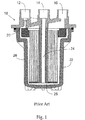
現在のインパクトフィルタの断面図が、図1に見られる。図1は、それぞれ独立型のマニホルドに接続するか、Mykrolis Corporationによって製造されたRGEN(登録商標)やインテリジェン(登録商標)ディスペンスシステムなどのディスペンスシステムに直接接続することができる、3つの独立な接続部、ベント12、供給口14および出口16を使用している装置を提供する。プロセス流体は、取入ポート14を通って入り、取入チューブ24を通って、ハウジング底部25へ流れる。その後、プロセス流体は、鉛直のメンブレンフィルタ26を通って、排出ポート16へ流れ、そこで、浄化された流体がマニホルドまたはディスペンスシステムへ戻るように方向付けられる。ベントポート12は、フィルタの上流側に蓄積した気泡をハウジング22へ排出する。フィルタから気泡をよりよく除去するために、ハウジングキャップ18の最上部表面が、ベントポート12の方を向く上向きの角度で設置されている。このことによって、気泡が、ハウジング20内の最高点に徐々に上昇し、ハウジング22から出ることができる。
【0003】
インパクトLHVDフィルタの特性および利点のより詳細な説明は、M.ClarkeおよびKwok−Shun Chengによる「New Photochemical Filtration Technology for Process Improvement」という題名のMykrolis Applications Note No.MA068に見られる。この論文は、最初は1997年11月10日のINTERFACE‘97ポスターセッションで発表された。これは、http://www.mykrolis.com/micro/appnotesliq.nsf/docs/48LQ63で入手可能である。また、インパクトLHVDの利点が、M.Clarkeによる「Improving Photolithography Equipment OEE with the IMPACT ST Manifold」という題名のMykrolis Applications Note No.MAL109で示されている。これは、http://www.mykrolis.com/micro/appnotesliq.nsf/docs/46AK7Bで入手可能である。
【0004】
インパクトLHVDフィルタの設計および性能は、他の濾過装置よりもずっと改良されているが、気泡通気についてはそれでもなお十分には最適化されていない。インパクトLHVDフィルタでは、気泡を含んだ流体が装置の底部へ押しやられ、流体で底部を掃引して、底部での流体の停滞およびジェル粒子の形成を防ぐ。このため、その後いかなる混入気泡もベントへ上昇しなければならない。また、底部からゆっくりと上昇する気泡は、装置から除去するために、より多くの時間と化学薬品を必要とすることになる。
【0005】
フィルタ、および標準的な濾過システムやディスペンスシステムにおけるフィルタの使用方法の不十分な点を補償するために、マイクロリスは、「2ステージテクノロジ」すなわちTSTと呼ばれる一体型の濾過およびディスペンスシステムを開発した。これらTSTシステムの設計によって、気泡を含む流体が再循環できるようにして、新しいフィルタの始動中に浪費される流体の量を最小化することができる。これらのシステムは、フィルタからより効率的に気泡を除去し、流体を節約するが、通気プロセスが最適化されていないため、無駄はまだ発生する。
【0006】
2ステージテクノロジシステムの動作のより詳細な記述が、M.Clarkeによる「Understanding the Operating Cycles of Millipore Two−Stage Technology Photochemical Dispense Systems」という題名のMykrolis Applications Note No.MAL111で示されている。これは、http://www.mykrolis.com/micro/appnotesliq.nsf/docs/46FSWGで入手可能である。
【0007】
これらのシステムのすべて(TSTシステムさえ含めて)について、通気プロセスが、気泡だけでなく、気泡で飽和された流体流も解放するため、気泡通気はまだ最適化されていない。多くのプロセス流体では、気泡が迅速に上昇しないため、ベントへ向かう流体の運動が、気泡を除去するために必要である(効率的には、気泡が流体流に沿って運ばれる)。また、除去される気泡がより小さいほど、流れへ排出される流体はより多い。
気泡が、半導体製造者の関心事であることが、上述のアプリケーションノートおよび議論から明らかである。しかし、現行のインパクトフィルタまたはその他の現在市販されている製品は、濾過装置の全ての表面から気泡を掃引すると同時に濾過前に気泡の除去を開始することの必要性に十分対処していない。
【0008】
したがって、濾過される液体からの気泡の除去を濾過前に開始して除去される気泡をベントの近くに位置決めし、それによって濾過される液体からの気泡の除去を容易にする液体濾過装置を提供することが望ましいであろう。また、流体損失の量を最小化する液体濾過装置の自動通気をする手段を提供するシステムを有することが望ましい。
【0009】
発明の概要
本発明は、液体濾過装置から気体のポケットを除去するために、特定のフローチャネルに結合された、装置内の流体の速度を使用することによって流体から気泡を除去する装置を提供する。適切に設計された流路が、気泡が最も集まりやすい位置へ流体を方向付ける。
【0010】
本発明は、より迅速で、より効率的な、混入気泡の除去を可能にする、ハウジングカバーを有するハウジング内の液体から気泡を除去するための装置および方法を提供する。新規な装置および方法は、装置内のフィルタカートリッジのフランジの下側面の周囲を掃引するために、装置入口での流体速度の一部を使用する。このことによって、流体内の気泡をフィルタメンブレンの上方、およびハウジングカバー内部表面の近傍に上昇させることになる。その後、フィルタカートリッジフランジの下方に位置決めされた液体流は、ハウジングカバーの内部表面に集中し、気泡を、流体から装置のベントポートに向かって押しやり続ける。
【0011】
また、本発明は、濾過される流体からの気泡の自動的ベントを行う方法を提供する。
【0012】
ベントサイクル中、装置内の流体から気泡を除去する液体濾過装置を提供することが、本発明の目的である。
【0013】
装置が濾過サイクルで動作している間、装置内の表面を使用することによって、流体から気泡を除去する液体濾過装置を提供することもまた、本発明の目的である。
【0014】
特定の実施形態の説明
濾過中の流体から除去された気泡と、本発明の濾過装置内で濾過された流体の両方の流れの方向は、装置が操作されるモードに依存している。本発明の濾過装置は、ベントを開放または閉鎖して、動作させることができる。濾過装置の初期動作モードでは、濾過装置は、流体で満たされており、装置から気体および気泡の大部分を除去するために、追加の流体がベントを開放した装置を通ってポンピングされる。この動作モード中、気泡を含んだ流体も、ベントを通過する。この初期動作モードに続いて、ベントが閉鎖され、濾過中の流体が本発明の濾過装置を通ってポンピングされる。このモード中、気泡が、絶えず濾過中の流体から分離されて、ベントの所で、またはベントの近くで収集される。好ましい動作モードでは、浪費される流体の量を最小化するために、流体は、ある期間濾過装置を通って再循環され、フィルタの孔から完全にまたは実質的に完全に気体を除去することを確実にされる。特定の間隔でベントは開放され、濾過装置から気泡が排出される。その後、ベントが閉鎖され、気泡のない流体を、使用ポイントへディスペンスすることができる。ある期間の経過後、装置は追加の気泡を収集することになり、別のベント動作が必要となる。再び、気泡および流体がベントを通って排出される。
【0015】
流体内に混入した気泡は、流体から濾過装置内の2つの位置の一方に沿って押しやられる。第1チャネルが、濾過装置のハウジングカバー内に、ベントと直接流体連絡するように位置決めされている。第2チャネルが、濾過装置のフィルタメンブレン上方のトップキャップ内に、第1チャネルと直接流体連絡するように位置決めされている。第1チャネルは、流体が濾過装置内に入るとき、流体からの気泡を蓄積する。第1チャネルはまた、第2チャネル内から回収された気泡を受けるように位置決めされている。第2チャネルは、濾過装置の濾過メンブレンの上流側で収集された、または形成された、いずれの気泡も蓄積する。このようにして、濾過装置は、濾過装置に入る際に直ちに流体から解放された気泡、および濾過前に流体から解放された気泡を回収する。
【0016】
本発明は、気泡をそこから除去することを容易にする内部流路を有する液体濾過装置を提供する。この装置はハウジングを備え、このハウジングは、ボウル、キャップ、およびカバーを含む。このカバーは、内部表面および外部表面を有し、その中で、液体入口、出口およびベントとして働く開口により特徴付けられる。そしてこれをもって、前記キャップ、カバー、およびボウルは液体チャネル群が形成されるように組み合わされる。前記チャネル群は、ベントが配置された前記ハウジングの部分に向かって液体を方向付ける流体チャネルと、前記ボウルの底部を掃引するように液体を方向付ける流体チャネルと、前記キャップの下側表面を掃引するように流体を方向付ける流体チャネルとを含んでいる。
【0017】
好ましい実施形態では、この装置は、入口およびベントの流体流路断面積が、最適な流速が気泡の除去および分離のために達成されて、それによって気泡の除去効率を増加させるように制御されるように設計されている。
【0018】
好ましい実施形態では、前記トップキャップの下側面は、ベントおよび濾過サイクル中ならびにサイクルの間に使用される、底部および頂部を有する傾斜した表面を有する。このような傾斜した表面は、装置からの気泡の除去を容易にする。好ましくは、表面頂部は、気泡がより効率的に除去されるように前記ベント開口と並置されている。
【0019】
好ましい実施形態では、ベント経路は、キャップとカバーの間の空間の底部でまたは底部の近くで収束している。この空間は、除去される気泡が集まる場所であることを理解されたい。本実施形態のために好ましいことに、表面頂部は、気泡が流体からより効率的に除去されるように前記ベント開口と並置されている。
【0020】
本発明の好ましい実施形態では、カバーの内部表面は、ベントリッジを有し、前記ベントリッジの頂部が、ベント開口の実質的に近傍に位置決めされている。
【0021】
別の好ましい実施形態では、ベントは、ベント開口のすぐ上に配置され、流体から気体を押し出すための流速を維持するためにベント流体経路を制限している。
【0022】
別の好ましい実施形態では、通気プロセスは、通気プロセス中に最小の流体が失われるように自動的に制御されている。
【0023】
本発明は、液体を濾過するよう意図された装置から気泡を除去する方法を提供する。前記装置は、入口、出口、およびベントを含み、濾過および通気プロセスの両方を対象とすることによって特徴付けられる。この方法は、濾過および通気プロセス中に掃引される液体チャネル群を設けることを含む。気泡をその装置の表面からベントへと掃引するのを容易する流体チャネル群が設けられ、それによって、濾過およびベントのいずれにおいてこの装置を使用しても、この装置から気泡が除去される。
【0024】
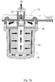
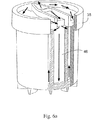
図2aおよび2bを参照すると、本発明の装置は、ハウジングカバー36から形成された、出口30、入口32およびベント34を備える。ハウジングカバー36は、トップキャップ38およびハウジングボウル42にぴったり納まっている。濾過媒体40が、ハウジングボウル42内に入れられている。矢印は、流体がどのように装置内を流れるかを示している。ダイバータ44が、流体の流路を入口からベント34の方へ変更する。濾過装置が流体を濾過しているとき、流体の大部分は、ベント34の近傍に気泡を付着させながら直接入口32からハウジングボウル42へ通過する。ハウジングカバー36は、ハウジングカバー36の全周または実質的に全周の周りに延び、ベント34の方へ方向付けられた、気体および気泡の通路を提供する第1チャネル31を備える。トップキャップ38は、トップキャップ38の実質的に全周囲に延び、入口流体からの気体が第1チャネル31へ入り、それからベント34を通り抜けるよう方向付けるための通路を提供する第2チャネル33を備える。
【0025】
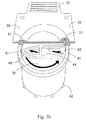
図3aおよび3bを参照すると、ハウジングカバー36は、ハウジングカバー36のベント側35の方へ角度を付けられた、その内部表面37を有する。第1チャネル31は、ハウジングカバー36の出口39側からベント34(図2b)へ螺旋状に至り、すべての追加の気体の気泡を除去する。
【0026】
また、図3aおよび3bに示すように、入口流体は、この特定の設計では、ダイバータ44によってハウジング中央からハウジングのベント34(図2b)が配置されている側へ方向が変えられる。この構成は、気泡を含んだ流体を入口32(図2b)から押しやって、ベント34(図2b)の方へ移動させる。断面積を制御することによって、浮力および滞留時間が効率的な気泡除去のために最適化されるように、流速を調整することができる。流体は、その後、側部流体チャネル46を下りて行く。
【0027】
図4aおよび4bは、カットアウト52を通ってトップキャップ38(図2b)の下に方向付けられ、その後そこで分割される入口流体を図示している。流体の大部分は、ボウル42(図2b)の内側に見られる2つのリブ49で形成された側部流体チャネル46を下り、ハウジングボウル底部25(図6b)を掃引し、流体の滞留部およびゲル粒子の形成を防ぐ。入口流体の他の部分は、流体チャネル53および54へ流入し、トップキャップ38(図2b)下側面の周囲のガスポケットを掃引する。トップキャップ38(図2b)とハウジングボウル42(図2b)の間に機械的密閉を形成することによって、流体がトップキャップ38(図2b)の下側を移動し、その後カットアウト51を通って反対側面の上方に戻ることを可能にする流路が、2つのチャネル53および54によって生成される。
【0028】
図5は、トップキャップ密封リッジ55の下に短い距離に配置された、入口流体をボウル42(図2b)の底部およびトップキャップ38(図2b)の下側面を掃引するように方向付ける2つの大きめのリブ49を示している。
【0029】
図6aおよび6bは、矢印によって示すような液体の流れを示している。入口流体は、リブ49(図5)によって形成された側部チャネル46の下流へ方向付けられ、濾過媒体40(図2b)とボウル42底部の内部表面との間の空間を掃引する。流体はまた、チャネル53および54(図4b)を通ってトップキャップ38の下側面を掃引するように方向付けられる。
【0030】
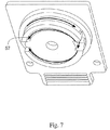
図7は、気体の気泡を除去するために、徐々に増加する傾斜によって、第2チャネル33(図2b)を通ってトップキャップ38(図2b)の下側面57を巡るように方向付けられたときの流体の流れを示している。
【0031】
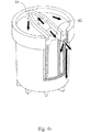
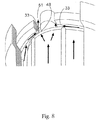
図8は、気泡を、第2チャネル33を通り、カットアウト51を通り、トップキャップ38(図2b)の上方へ、トップキャップ38(図2b)とカバー36(図2b)の間の空間内へ方向付けるアクセスポイント48へ集中する流路を示している。
【0032】
図9は、ハウジングカバー36(図2b)の下の空間の最下位置(底部)58でトップキャップ38の上方へ戻るように方向付けられた流路を示している。これによって、液体が、気泡をトップキャップ38(図2b)の下側面に沿ってチャネル31(図2b)へ確実に押しやる。
【0033】
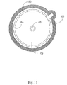
図10は、制限された流体の流路71を有するハウジングカバー88が、チャネル73に沿った流体の流れの反転を防止するように設けられていることを示している。制限された流路71は、通気プロセスのみの間、境界面が掃引されることを可能にする。通気プロセス中、流体入口93に流入する少量の流体のみがベント92へ直接通過することができ、一方で、残りの流体の流速が維持されて、濾過カートリッジ40(図2b)のトップキャップ81(図11)の下の流体の流れを継続させ、トップキャップ81の下側面を掃引する。流体は、その後、小さい断面積によって流速をより容易に維持することができるベント溝73のアクセスポイント84へ集中する。逆に、気体ベント92への制限されないアクセスでは、濾過プロセス中にカートリッジの掃引を行わなければならず、したがって、通気プロセスよりも、またはベントおよび濾過プロセスの両方よりも効率的でない。ハウジングカバー70は、ベント92と、流体入口93と、流体出口75とを備える。内部表面90および77は共に、気体ベントリッジ87の方へ傾斜して、気体ベント92への気体の流れを容易にしている。図11に示すように、トップキャップ81の下側面94は、チャネル73(図10)と流体連絡しているアクセスポイント84へ集中する気体チャネル83を備える。トップチャネル81もまた、出口75(図10)と流体連絡している出口85を備える。図11のトップキャップはハウジングカバー88に接合されて、領域86を遮蔽し、それによって、停滞容積を減少させ、濾過装置への流体の流路を形成する。
【0034】
本発明はまた、流体を濾過およびディスペンスするためのシステム内での本発明の液体濾過装置の操作方法を提供する。典型的な使用例(シングルステージテクノロジとも呼ばれる)では、フィルタが、ディスペンス機構(たとえばダイアフラムポンプ、加圧キャニスタなど)と、流体を半導体ウェハや光ディスクなどの基板上に方向付けるノズルとの間に乾式で設置される。フィルタの孔から空気を除去するために、プロセス流体が、フィルタ内へ押し入れられ、それぞれの流体流が目に見える気泡を含まなくなるまで、ベントと排出ポートの両方から流し出される。不運なことに、ベントおよび出口から送り出された流体は、多数の気泡を含んでおり、この気泡が、被覆された基板上または基板内の欠陥を引き起こす可能性があることはよく知られている。そのため、この気泡を含んだ流体は、通常、浪費されるように方向付けられ、再利用されない。この使用法は、かなりの量の流体を消費することがある。プロセス流体は、高価(1リットル当たり1,000ドル〜10,0000ドル)である可能性があり、より効率的に気泡を除去することによって、無駄を最小にすることが重要である。
【0035】
典型的な濾過装置は、気泡を除去するように最適化されてはいない。気泡を除去するための好ましい操作指向は、底部に流体入口、および最上部にベントを備えるフィルタを使用している。これは、大きな気体気泡を装置から効率的に除去するが、入口を通って導入された、より小さい気泡は、メンブレンの外側面に沿ってゆっくりと上昇する。これらの気泡を装置の上流側から除去するには、かなりの時間がかかり、流体を浪費する。また、気泡は、メンブレンによって吸収されることがあり、その結果、濡れない(de−wet)スポットが、フィルタの短い寿命および気泡に誘引された基板の欠陥という結果をもたらす。
【0036】
TSTシステムでは、マイクロプロセッサが、多くのプロセスの利益のために、間にフィルタを有する2つのポンプの動作を制御している。これらのシステムの設計はまた、新しいフィルタの始動中に浪費される流体の量を最小化するために、気泡を含んだ流体を再循環させることができる。乾いたフィルタの始動中、流体は、フィルタを通って下流側へ押し出され、そこで、(フィルタメンブレンの孔から除去された気体からの)気泡を含んだ流体が、ポンプの入口へ循環して戻される。この流体は、次にフィルタの上流側へ戻される。ここで、メンブレンの孔がプロセス流体で充填されているため、メンブレンは、気泡の通過に対してより効率的な(しかし完全には効率的ではない)遮蔽物となる。従来技術のインパクトLHVDフィルタでは、気泡を含んだ流体は、フィルタの底部へ方向付けられる。そのとき、気泡は、浮力により浮き上がってベントに至り、ベントにて、自動的手段(ソフトウェア起動されるベントバルブ)または手動の手段(手動で駆動されるベントバルブ)のいずれかによって除去される。このことは、フィルタから気泡を除去し、流体を節約するためのより効率的な方法であるが、通気プロセスが最適化されていないため、まだ無駄が発生する。これらすべてのシステムでは、通気プロセスが、気泡だけでなく気泡で飽和された流体流までも解放するため、気泡の通気は最適化されていない。多くのプロセス流体では気泡は迅速に上昇しないため、気泡を除去するためにベントへ向かう流体の運動が必要とされる(効率的には、気泡が流体流に沿って運ばれる)。また、除去すべき気泡がより小さいほど、より多くの流体が、流れで排出される。
【0037】
本発明の液体濾過装置による気泡の通気は、フィルタの通気を自動的に制御するためのアルゴリズム(「スマート通気」)を使用することができる。特に、スマート通気は、フィルタがベントサイクルを行う回数を制限し、各ベントサイクル中に失われる流体の量を制限することになる。
【0038】
通常、始動中および動作中、以下のようにフィルタがベントされる。
(A)フィルタ始動中のTSTシステムでは、フィルタは、捕捉された気泡を除去するために5サイクル毎にベントされる。通常、ベントバルブは、250ミリ秒間開放し、約50〜150マイクロリットルの流体が送られて、浪費される。典型的な始動および前調整プロセス中、フィルタは200回以上ベントされることがある。したがって、このプロセスは、約10ミリリットル〜30ミリリットルの間の流体を浪費する。また、通常動作中、フィルタはサイクル毎にベントされ、再び、50〜150マイクロリットルの間の流体が、ディスペンス毎に失われるという結果になる。
(B)TSTではない使用例では、通気は通常手動プロセスであり、操作者の判断および都合による。始動中、通気はより頻繁であり、手動態様の通気は、50〜100ミリリットルの間の流体損失という結果になる。また、通常フィルタ下流の流体の再循環はないため、それに加えて500〜1500ミリリットルがフィルタの調整で浪費されることがある。最後に、操作中、通気は1日に1回行われることがあり、再び、各回で20から30ミリリットルの間の流体が失われることがある。
【0039】
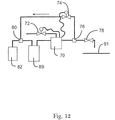
本発明の液体濾過装置では、スマート通気が、プログラム可能であり、自動化されている。シングルステージシステムでは、これは、「インテリジェント」マニホルドおよび本発明の装置を使用することによって達成される。現在のインパクトSTマニホルドは、受動型装置であるが、マイクロセッサおよびいくつかの流体接続部(例えば、ソレノイドバルブ、ティー)を追加することによって、スマート通気を行うようにすることができる。このようなシステムの説明が、図12に示されている。この図では、本発明の濾過装置70を備えるマニホルドが、ソレノイドベントバルブ72およびソレノイド再循環バルブ74の動作を制御する。本発明の装置を備えるマニホルドはまた、ポンプ89と連絡している。ティー結合部76は、再循環バルブ74を通るか、ストップアンドサックバックバルブ78を通って基板84へ至るかのいずれかに流体を方向付けることができるように配置されている。ティー80は、通常動作中は流体源82から、および流体がマニホルドおよび濾過装置70へ再循環されるときはバルブ74から共に流体を受けるように配置されている。新しいフィルタの始動時、再循環バルブ74およびストップアンドサックバックバルブ78は閉鎖され、ベントバルブ72が開放される。その後流体は濾過装置のハウジングを充填するためにマニホルド内に送られる。ハウジングが満たされた後、ベントバルブ72が閉鎖され再循環バルブ74が開放している間、流体は自動的に再循環することができ、それによってベント損失が最小化される。再循環中選択された回数(時間指定されてか、あるサイクル数の後かのどちらか)で、再循環バルブ74が閉鎖され、ベントバルブ72が開放されて、マニホルドおよびフィルタ70から気体が除去される。フィルタが準備された後、バルブ74が閉鎖され、バルブ78が開放されて、それによって流体を基板91上に付着されることができる。
【0040】
大部分の場合、通気の間のサイクル数は、本発明の装置を使用することによって長くすることができる。気泡が濾過装置の最上部で優先的に捕捉され、凝集するため、フィルタメンブレンに接触する、もしくはフィルタメンブレンの側を通過することはない。このように、気泡は、濡れないスポットを形成(すなわち、より短いフィルタ寿命をもたらす、または気泡に誘引された基板欠陥を導く)しないことになる。したがって、通気プロセス間の時間を延長することができる。
【0041】
また、ベントバルブの開放(時間および幾何形状)を最小化することができる。近年、ベントバルブは、気泡を含んだ流体がバルブを通って流れることができるようにするために、十分開放させなければならない。しかし、気泡は、凝集してより大きい気泡になるため、空気(より小さい粘性を有する)は、小さい通路を通って流体よりも容易に流れ、ベントをよりわずかに短い時間間隔で開放することは、流体の通過を許すことなく、空気を通過させることを可能にする。これは、短いベント開放時間を設定することか、ベントバルブを、その開放オリフィス面積を最小化するように制御することかのどちらかによって達成することができる。両方とも、様々な粘性の流体に対してバルブの開放を最小化することに効果があり、またベントを通る流体損失を最小化することになる。
【0042】
本発明の自動操作方法を、以下の特徴を組み込むことによってさらに改良することができる。
(A)メンブレンコンタクタタイプの脱気装置をシステムに設置する。この脱気装置は、フィルタのベントライン上に設置することができる。また、シングルステージシステムでは、脱気装置はフィルタの上流にすることができ、ツーステージテクノロジシステムでは、ポンプの上流側に配置される(しかし、ラインの下流は、始動中流体を再循環させるために使用される)。このような脱気装置は、流体流に影響を与えることなく、気泡を除去し、マイクロバブルの形成を防ぐ。これは、通常動作中の通気を実用上排除するという利点も有する。他の脱気装置手段(たとえば、スパージング、加熱、真空吸引など)を使用することもできるが、これらの手段は通常、プロセス流体の望ましくない変化(たとえば、溶媒の蒸発による粘性の変化)という結果になる。
(B)ベントライン、フィルタ自体のべントポート、または濾過装置をツーステージテクノロジシステムに接続するマニホルドのいずれかに、気泡検出器を設置する。そのとき、マイクロプロセッサによって読み出された信号によって気泡検出器が十分な量の気体を感知したときのみ、通気が可能になる。また、通気は、気泡のみをベントし、流体はベントしないように制御することができる。
【図面の簡単な説明】
【図1】
従来技術の図であり、インパクトLHVDフィルタの断面図である。
【図2a】
流体流路を表す矢印を有する、本発明の濾過装置の横断面図である。
【図2b】
流体流路を表す矢印を有する、本発明の濾過装置の横断面図である。
【図3a】
本発明の濾過装置のトップキャップの下側面図である。
【図3b】
本発明の濾過カートリッジ上のキャップに対して位置決めされた図3aのトップキャップの部分横断面図である。
【図4a】
流体流路を表す矢印を有する、流体チャネルを示す本発明の部分断面図である。
【図4b】
図4aの装置の下側面図である。
【図5】
本発明の濾過装置のボウルの上面図である。
【図6a】
流体流路を表す矢印を有する、流体チャネルを示す本発明の部分断面図である。
【図6b】
図6aの装置の下側面図である。
【図7】
流体流路を表す矢印を有する、トップキャップおよびハウジングの下側面図である。
【図8】
流体チャネルと、流体流路を表す矢印を示す本発明の部分断面図である。
【図9】
流体チャネルと、気泡をフィルタカートリッジ上方へ押しやる流体流路アクセスポイントの集中を示す本発明の部分断面図である。
【図10】
本発明の別のハウジングカバーの底面図である。
【図11】
図10のハウジングカバーとともに使用される本発明の別のトップキャップの底面図である。
【図12】
本発明の装置を動作させる自動化された方法を示す流れ図である。[0001]
Background of the Invention
Impact® LVHD filters sold by Mykrolis Corporation of Bedford, Mass. Have a low stagnation volume, which means that the process fluids that are primarily filtered by the device, ie, photoresist, dielectric, reflective It is very advantageous because of the high cost of the inhibitor and the optical disc material. Impact LHVD filters provide excellent filtration and prevent debris in the process fluid from depositing on the substrate and causing defects.
[0002]
A cross section of a current impact filter can be seen in FIG. FIG. 1 shows three independent dispense systems that can each be connected to a stand-alone manifold or directly to a dispense system such as RGEN® or Intelligence® dispense system manufactured by Mykrolis Corporation. An apparatus is provided that uses connections,
[0003]
A more detailed description of the characteristics and advantages of an impact LHVD filter can be found in: Myrkolis Applications Note No. entitled "New Photochemical Filtration Technology for Process Improvement" by Clarke and Kwok-Shun Cheng. See MA068. This paper was first presented in an INTERFACE '97 poster session on November 10, 1997. This is available at http: // www. mykrolis. com / micro / appnotesliq. Available at nsf / docs / 48LQ63. Also, the advantage of Impact LHVD is that Clarke, entitled "Improving Photolithography Equipment OEE with the IMPACT ST Manifold", Mykrolis Applications Note No. This is indicated by MAL109. This is available at http: // www. mykrolis. com / micro / appnotesliq. Available at nsf / docs / 46AK7B.
[0004]
Although the design and performance of impact LHVD filters are much improved over other filtration devices, bubble ventilation is still not fully optimized. In an impact LHVD filter, fluid containing air bubbles is forced to the bottom of the device and sweeps the bottom with the fluid, preventing fluid stagnation and gel particle formation at the bottom. For this reason, any entrained air bubbles must then rise to the vent. Also, air bubbles that rise slowly from the bottom will require more time and chemicals to be removed from the device.
[0005]
To compensate for the deficiencies of filters and the use of filters in standard filtration and dispensing systems, Microlith has developed an integrated filtration and dispensing system called "two-stage technology" or TST. . The design of these TST systems allows the fluid containing the bubbles to be recirculated, minimizing the amount of fluid wasted during the startup of a new filter. These systems more efficiently remove air bubbles from the filter and save fluid, but waste still occurs because the ventilation process is not optimized.
[0006]
A more detailed description of the operation of a two-stage technology system can be found in Clarke's Mykrolis Applications, "Understanding the Operating Cycles of Millipore Two-Stage Technology Photochemical Dispense Systems". This is indicated by MAL111. This is available at http: // www. mykrolis. com / micro / appnotesliq. Available at nsf / docs / 46FSWG.
[0007]
For all of these systems (including even the TST system), bubble ventilation has not yet been optimized because the ventilation process releases not only the bubbles but also the fluid flow saturated with the bubbles. In many process fluids, the movement of the fluid toward the vent is required to remove the bubbles because the bubbles do not rise quickly (effectively, the bubbles are carried along the fluid stream). Also, the smaller the bubbles that are removed, the more fluid that is discharged into the stream.
It is clear from the application notes and discussions above that air bubbles are of concern to semiconductor manufacturers. However, current impact filters or other currently commercially available products do not adequately address the need to sweep air bubbles from all surfaces of the filtration device while simultaneously starting to remove air bubbles prior to filtration.
[0008]
Accordingly, there is provided a liquid filtration device that initiates removal of air bubbles from a liquid to be filtered prior to filtration and positions the air bubbles to be removed near a vent, thereby facilitating the removal of air bubbles from the liquid to be filtered. Would be desirable. It would also be desirable to have a system that provides a means for automatically venting a liquid filtration device that minimizes the amount of fluid loss.
[0009]
Summary of the Invention
The present invention provides an apparatus for removing air bubbles from a fluid by using the velocity of the fluid in the apparatus, coupled to a particular flow channel, to remove gas pockets from the liquid filtration apparatus. Properly designed flow channels direct fluid to locations where bubbles are most likely to collect.
[0010]
The present invention provides an apparatus and method for removing air bubbles from a liquid in a housing having a housing cover that allows for faster and more efficient removal of entrained air bubbles. The novel device and method uses a portion of the fluid velocity at the device inlet to sweep around the underside of the filter cartridge flange in the device. This causes bubbles in the fluid to rise above the filter membrane and near the interior surface of the housing cover. Thereafter, the liquid flow positioned below the filter cartridge flange concentrates on the interior surface of the housing cover and continues to push air bubbles from the fluid toward the vent port of the device.
[0011]
The present invention also provides a method for automatically venting air bubbles from a fluid to be filtered.
[0012]
It is an object of the present invention to provide a liquid filtration device that removes air bubbles from the fluid in the device during a vent cycle.
[0013]
It is also an object of the present invention to provide a liquid filtration device that removes air bubbles from a fluid by using surfaces within the device while the device is operating in a filtration cycle.
[0014]
Description of specific embodiments
The direction of flow of both the bubbles removed from the fluid being filtered and the fluid filtered in the filtration device of the present invention depends on the mode in which the device is operated. The filtration device of the present invention can be operated with the vent open or closed. In the initial mode of operation of the filtration device, the filtration device is filled with fluid and additional fluid is pumped through the vented device to remove most of the gases and bubbles from the device. During this mode of operation, fluid containing air bubbles also passes through the vent. Following this initial mode of operation, the vent is closed and the fluid being filtered is pumped through the filtration device of the present invention. During this mode, air bubbles are constantly separated from the fluid being filtered and collected at or near the vent. In a preferred mode of operation, the fluid is recirculated through the filtration device for a period of time to completely or substantially completely remove gas from the filter holes to minimize the amount of fluid wasted. Will be assured. At specific intervals, the vents are opened and air bubbles are exhausted from the filtration device. Thereafter, the vent is closed and the bubble-free fluid can be dispensed to the point of use. After a period of time, the device will collect additional air bubbles and another venting operation will be required. Again, bubbles and fluids are exhausted through the vent.
[0015]
Air bubbles entrained in the fluid are forced from the fluid along one of two locations in the filtration device. A first channel is positioned within the housing cover of the filtration device for direct fluid communication with the vent. A second channel is positioned in the top cap above the filter membrane of the filtration device for direct fluid communication with the first channel. The first channel accumulates bubbles from the fluid as it enters the filtration device. The first channel is also positioned to receive air bubbles collected from within the second channel. The second channel accumulates any air bubbles collected or formed upstream of the filtration membrane of the filtration device. In this way, the filtration device collects air bubbles released immediately from the fluid upon entering the filtration device and air bubbles released from the fluid prior to filtration.
[0016]
The present invention provides a liquid filtration device having an internal flow path that facilitates removing air bubbles therefrom. The device includes a housing, which includes a bowl, a cap, and a cover. The cover has an inner surface and an outer surface, and is characterized by openings therein, which serve as liquid inlets, outlets and vents. Thus, the cap, cover and bowl are combined so that a liquid channel group is formed. The group of channels includes a fluid channel that directs liquid toward a portion of the housing where the vent is located, a fluid channel that directs liquid to sweep the bottom of the bowl, and a sweeping lower surface of the cap. And a fluid channel for directing the fluid to operate.
[0017]
In a preferred embodiment, the apparatus controls the inlet and vent fluid flow cross-sections such that optimal flow rates are achieved for bubble removal and separation, thereby increasing bubble removal efficiency. It is designed to be.
[0018]
In a preferred embodiment, the lower surface of the top cap has an inclined surface with a bottom and a top used during and during venting and filtration cycles. Such a sloped surface facilitates the removal of air bubbles from the device. Preferably, the top of the surface is juxtaposed with said vent opening so that air bubbles are more efficiently removed.
[0019]
In a preferred embodiment, the vent path converges at or near the bottom of the space between the cap and the cover. It should be understood that this space is where the bubbles to be removed collect. Preferably, for this embodiment, the top of the surface is juxtaposed with the vent opening so that air bubbles are more efficiently removed from the fluid.
[0020]
In a preferred embodiment of the invention, the inner surface of the cover has a vent ridge, the top of said vent ridge being positioned substantially near the vent opening.
[0021]
In another preferred embodiment, the vent is located just above the vent opening and restricts the vent fluid path to maintain a flow rate for pushing gas out of the fluid.
[0022]
In another preferred embodiment, the venting process is automatically controlled such that minimal fluid is lost during the venting process.
[0023]
The present invention provides a method for removing air bubbles from a device intended to filter a liquid. The device includes inlets, outlets, and vents and is characterized by being targeted for both filtration and aeration processes. The method includes providing a group of liquid channels that are swept during a filtration and aeration process. Fluid channels are provided that facilitate sweeping air bubbles from the surface of the device to the vent, thereby removing air bubbles from the device, whether the device is used in filtration or venting.
[0024]
Referring to FIGS. 2 a and 2 b, the device of the present invention comprises an
[0025]
Referring to FIGS. 3 a and 3 b, the
[0026]
Also, as shown in FIGS. 3a and 3b, the inlet fluid is redirected from the center of the housing by this
[0027]
4a and 4b illustrate the inlet fluid being directed through the
[0028]
FIG. 5 shows two, positioned a short distance below the top
[0029]
6a and 6b show the flow of liquid as indicated by the arrows. The inlet fluid is directed downstream of the
[0030]
FIG. 7 is directed through the second channel 33 (FIG. 2b) and around the
[0031]
FIG. 8 shows that air bubbles are passed through the
[0032]
FIG. 9 shows the flow path oriented to return above the
[0033]
FIG. 10 shows that a
[0034]
The present invention also provides a method of operating the liquid filtration device of the present invention in a system for filtering and dispensing a fluid. In a typical use case (also called single-stage technology), a filter is a dry-type filter between a dispensing mechanism (eg, a diaphragm pump, a pressure canister, etc.) and a nozzle that directs fluid onto a substrate, such as a semiconductor wafer or optical disk. Installed in To remove air from the filter holes, process fluid is forced into the filter and flows out of both the vent and the exhaust port until the respective fluid stream contains no visible air bubbles. Unfortunately, it is well known that the fluid delivered from vents and outlets contains a large number of air bubbles, which can cause defects on or within the coated substrate. . As such, the fluid containing the bubbles is typically directed to waste and is not reused. This use can consume a significant amount of fluid. Process fluids can be expensive ($ 1,000 to $ 10,000 per liter) and it is important to minimize waste by removing bubbles more efficiently.
[0035]
Typical filtration devices are not optimized to remove air bubbles. A preferred operating orientation for removing air bubbles uses a filter with a fluid inlet at the bottom and a vent at the top. This effectively removes large gas bubbles from the device, but smaller bubbles introduced through the inlet slowly rise along the outer surface of the membrane. Removing these bubbles from the upstream side of the device takes considerable time and wastes fluid. Also, bubbles may be absorbed by the membrane, resulting in de-wet spots resulting in a short life of the filter and substrate defects induced by the bubbles.
[0036]
In a TST system, a microprocessor controls the operation of two pumps with filters in between for the benefit of many processes. The design of these systems can also recirculate fluid containing air bubbles in order to minimize the amount of fluid wasted during startup of a new filter. During startup of a dry filter, fluid is forced downstream through the filter, where bubbled fluid (from gas removed from the filter membrane holes) is circulated back to the pump inlet. It is. This fluid is then returned to the upstream side of the filter. Here, because the pores of the membrane are filled with process fluid, the membrane becomes a more efficient (but not completely efficient) shield against the passage of bubbles. In prior art impact LHVD filters, the fluid containing air bubbles is directed to the bottom of the filter. At that time, the bubbles are lifted by buoyancy to the vent, where they are removed by either automatic means (software activated vent valve) or manual means (manually driven vent valve). This is a more efficient way to remove air bubbles from the filter and save fluid, but still wastes because the ventilation process has not been optimized. In all these systems, the ventilation of the bubbles is not optimized because the ventilation process releases not only the bubbles but also the fluid flow saturated with the bubbles. Since bubbles do not rise quickly in many process fluids, movement of the fluid toward the vent is required to remove the bubbles (effectively, the bubbles are carried along the fluid stream). Also, the smaller the bubbles to be removed, the more fluid will be expelled in the stream.
[0037]
The ventilation of bubbles by the liquid filtration device of the present invention can use an algorithm ("smart ventilation") to automatically control the ventilation of the filter. In particular, smart venting will limit the number of times the filter performs vent cycles and will limit the amount of fluid lost during each vent cycle.
[0038]
Typically, during startup and operation, the filter is vented as follows.
(A) In a TST system during filter startup, the filter is vented every 5 cycles to remove trapped air bubbles. Typically, the vent valve opens for 250 milliseconds, delivering about 50-150 microliters of fluid and wasted. During a typical startup and preconditioning process, the filter may be vented more than 200 times. Thus, this process wastes between about 10-30 ml of fluid. Also, during normal operation, the filter is vented every cycle, again resulting in between 50-150 microliters of fluid being lost per dispense.
(B) In non-TST use cases, venting is usually a manual process and is at the discretion and convenience of the operator. During startup, ventilation is more frequent, and ventilation in a manual manner results in a loss of fluid of between 50-100 milliliters. Also, since there is usually no recirculation of fluid downstream of the filter, an additional 500 to 1500 milliliters may be wasted in adjusting the filter. Finally, during operation, aeration may occur once a day and again between 20 and 30 milliliters of fluid may be lost each time.
[0039]
In the liquid filtration device of the present invention, smart venting is programmable and automated. In a single-stage system, this is achieved by using an "intelligent" manifold and the apparatus of the present invention. The current Impact ST manifold is a passive device, but can be made to provide smart ventilation by adding a microprocessor and some fluid connections (eg, solenoid valves, tees). A description of such a system is shown in FIG. In this figure, a manifold with a
[0040]
In most cases, the number of cycles during ventilation can be increased by using the device of the present invention. Bubbles are preferentially trapped and agglomerated at the top of the filtration device so that they do not contact the filter membrane or pass by the filter membrane. In this way, the bubbles will not form non-wetting spots (ie, resulting in shorter filter life or leading to substrate defects induced by the bubbles). Thus, the time between ventilation processes can be extended.
[0041]
Also, vent valve opening (time and geometry) can be minimized. In recent years, vent valves have to be sufficiently open to allow bubbled fluid to flow through the valve. However, air (having a lower viscosity) flows more easily than fluid through small passages, as bubbles aggregate into larger bubbles, and it is not possible to open the vents in slightly shorter time intervals. Allows air to pass without allowing the passage of fluid. This can be achieved either by setting a short vent opening time or by controlling the vent valve to minimize its opening orifice area. Both are effective in minimizing valve opening for fluids of various viscosities and will also minimize fluid loss through the vent.
[0042]
The automatic operation method of the present invention can be further improved by incorporating the following features.
(A) A membrane contactor type deaerator is installed in the system. This deaerator can be installed on the vent line of the filter. Also, in single-stage systems, the degasser can be upstream of the filter, and in two-stage technology systems, it is located upstream of the pump (but downstream of the line to recirculate fluid during startup). Used for). Such degassing devices remove bubbles and prevent the formation of microbubbles without affecting the fluid flow. This also has the advantage of practically eliminating ventilation during normal operation. Other degasser means (eg, sparging, heating, vacuum suction, etc.) may be used, but these means typically result in undesirable changes in the process fluid (eg, changes in viscosity due to evaporation of the solvent). become.
(B) Install the bubble detector either on the vent line, on the vent port of the filter itself, or on the manifold connecting the filtration device to the two-stage technology system. At that time, ventilation is enabled only when the bubble detector senses a sufficient amount of gas by the signal read by the microprocessor. In addition, the ventilation can be controlled so that only the air bubbles are vented and the fluid is not vented.
[Brief description of the drawings]
FIG.
It is a figure of prior art, and is sectional drawing of an impact LHVD filter.
FIG. 2a
FIG. 3 is a cross-sectional view of the filtration device of the present invention, having an arrow representing a fluid flow path.
FIG. 2b
FIG. 3 is a cross-sectional view of the filtration device of the present invention, having an arrow representing a fluid flow path.
FIG. 3a
It is a bottom view of the top cap of the filtration device of the present invention.
FIG. 3b
FIG. 3b is a partial cross-sectional view of the top cap of FIG. 3a positioned relative to the cap on the filtration cartridge of the present invention.
FIG. 4a
FIG. 3 is a partial cross-sectional view of the present invention showing a fluid channel with arrows representing fluid flow paths.
FIG. 4b
Fig. 4b is a bottom side view of the device of Fig. 4a.
FIG. 5
It is a top view of the bowl of the filtration device of this invention.
FIG. 6a
FIG. 3 is a partial cross-sectional view of the present invention showing a fluid channel with arrows representing fluid flow paths.
FIG. 6b
Fig. 6b is a bottom side view of the device of Fig. 6a.
FIG. 7
FIG. 5 is a bottom side view of the top cap and the housing, with arrows representing fluid flow paths.
FIG. 8
FIG. 3 is a partial cross-sectional view of the present invention showing fluid channels and arrows representing fluid flow paths.
FIG. 9
FIG. 4 is a partial cross-sectional view of the present invention showing the concentration of fluid channels and fluid flow access points that push air bubbles over the filter cartridge.
FIG. 10
It is a bottom view of another housing cover of the present invention.
FIG. 11
FIG. 11 is a bottom view of another top cap of the present invention used with the housing cover of FIG. 10.
FIG.
4 is a flow chart illustrating an automated method of operating the device of the present invention.
Claims (12)
ボウルと、
キャップと、
内部表面および外部表面を有し、その中で、流体入口、出口およびベントとして働く開口により特徴付けられるカバーとを含み、それによって前記キャップ、カバーおよびボウルが流体チャネル群を形成するように結合され、このようなチャネル群が、前記装置から前記ベントに向かって気泡を掃引することを容易にするハウジングを備え、前記チャネル群が、
前記ベントが配置された前記ハウジングの部分に向かって流体を方向付ける流体チャネルと、
前記ボウルの底部を掃引するように流体を方向付ける流体チャネルと、
前記キャップの下側表面を掃引するように流体を方向付ける流体チャネルとを含んでいる、流体濾過装置。A fluid filtration device comprising an internal flow path that facilitates removing air bubbles therefrom, comprising:
Bowl and
Cap and
A cover having an inner surface and an outer surface, wherein the cover is characterized by openings serving as fluid inlets, outlets and vents, whereby the cap, cover and bowl are coupled to form a group of fluid channels. Wherein such channels comprise a housing that facilitates sweeping air bubbles from the device toward the vent, wherein the channels comprise:
A fluid channel for directing fluid toward a portion of the housing where the vent is located;
A fluid channel for directing fluid to sweep the bottom of the bowl;
A fluid channel directing fluid to sweep the lower surface of the cap.
前記装置内の各位置に流体を方向付けるように位置決めされた、通気プロセス中に流れる流体を内包する流体チャネル群を設けること、および、
前記装置の表面からベントへの気泡の掃引を容易にし、それによって濾過または通気プロセスのいずれかで前記装置を使用することにより、前記装置からの気泡の除去を行う、濾過プロセス用の流体チャネル群を設けることを含む方法。A method for removing air bubbles from a device intended to filter a fluid, comprising: an inlet, an outlet, and a vent, wherein the method is intended for both a filtration cycle and a vent cycle.
Providing fluid channels containing fluid flowing during the venting process, positioned to direct fluid to respective locations within the device; and
Fluid channels for a filtration process that facilitate sweeping air bubbles from the surface of the device to a vent, thereby removing air bubbles from the device by using the device in either a filtration or aeration process. Providing a method.
Applications Claiming Priority (2)
| Application Number | Priority Date | Filing Date | Title |
|---|---|---|---|
| US23220900P | 2000-09-13 | 2000-09-13 | |
| PCT/US2001/028771 WO2002022232A1 (en) | 2000-09-13 | 2001-09-13 | Liquid filtration device |
Publications (2)
| Publication Number | Publication Date |
|---|---|
| JP2004508183A true JP2004508183A (en) | 2004-03-18 |
| JP2004508183A5 JP2004508183A5 (en) | 2005-02-24 |
Family
ID=22872266
Family Applications (1)
| Application Number | Title | Priority Date | Filing Date |
|---|---|---|---|
| JP2002526476A Pending JP2004508183A (en) | 2000-09-13 | 2001-09-13 | Liquid filtration device |
Country Status (8)
| Country | Link |
|---|---|
| US (5) | US6846409B2 (en) |
| EP (1) | EP1322395B1 (en) |
| JP (1) | JP2004508183A (en) |
| KR (1) | KR100582967B1 (en) |
| CN (1) | CN1183993C (en) |
| DE (1) | DE60144097D1 (en) |
| TW (1) | TW508260B (en) |
| WO (1) | WO2002022232A1 (en) |
Cited By (4)
| Publication number | Priority date | Publication date | Assignee | Title |
|---|---|---|---|---|
| JP2014087718A (en) * | 2012-10-29 | 2014-05-15 | 3M Innovative Properties Co | Filter device, assembly method of the same, filtration method using the same, and filtered fluid manufacturing method using the same |
| JP2014195807A (en) * | 2014-06-18 | 2014-10-16 | 株式会社ロキテクノ | Filter module attaching/detaching device and filtration unit |
| JP2015106656A (en) * | 2013-11-29 | 2015-06-08 | 東京エレクトロン株式会社 | Filter device |
| JP2017528643A (en) * | 2013-03-15 | 2017-09-28 | インテグレイテッド・デザインズ・リミテッド・パートナーシップIntegrated Designs,L.P. | Automatic gas removal and fluid recovery system and method using gas removal reservoir with internal partition |
Families Citing this family (42)
| Publication number | Priority date | Publication date | Assignee | Title |
|---|---|---|---|---|
| US6378907B1 (en) | 1996-07-12 | 2002-04-30 | Mykrolis Corporation | Connector apparatus and system including connector apparatus |
| WO2001095995A2 (en) * | 2000-05-12 | 2001-12-20 | Pall Corporation | Filters |
| EP1322395B1 (en) * | 2000-09-13 | 2011-02-23 | Entegris, Inc. | Liquid filtration device |
| US20030019819A1 (en) * | 2001-07-30 | 2003-01-30 | Karl Fritze | Hot disconnect replaceable water filter assembly |
| TWI245163B (en) * | 2003-08-29 | 2005-12-11 | Asml Netherlands Bv | Lithographic apparatus and device manufacturing method |
| TW200610573A (en) * | 2004-06-03 | 2006-04-01 | Mykrolis Corp | Fluid treating apparatus |
| US7393388B2 (en) * | 2005-05-13 | 2008-07-01 | United Technologies Corporation | Spiral wound fuel stabilization unit for fuel de-oxygenation |
| US7435283B2 (en) * | 2005-05-18 | 2008-10-14 | United Technologies Corporation | Modular fuel stabilization system |
| US7465336B2 (en) * | 2005-06-09 | 2008-12-16 | United Technologies Corporation | Fuel deoxygenation system with non-planar plate members |
| US7377112B2 (en) | 2005-06-22 | 2008-05-27 | United Technologies Corporation | Fuel deoxygenation for improved combustion performance |
| EP2471587B1 (en) * | 2005-07-22 | 2017-02-01 | Mann + Hummel GmbH | Fuel filter |
| US20070101731A1 (en) * | 2005-09-07 | 2007-05-10 | United Technologies Corporation | Deoxygenated fuel-cooled environmental control system pre-cooler for an aircraft |
| US9258259B2 (en) * | 2005-09-30 | 2016-02-09 | Nokia Technologies Oy | Retrieval of offline instant messages |
| US7615104B2 (en) | 2005-11-03 | 2009-11-10 | United Technologies Corporation | Fuel deoxygenation system with multi-layer oxygen permeable membrane |
| US20070130956A1 (en) * | 2005-12-08 | 2007-06-14 | Chen Alexander G | Rich catalytic clean burn for liquid fuel with fuel stabilization unit |
| US7582137B2 (en) * | 2006-01-18 | 2009-09-01 | United Technologies Corporation | Fuel deoxygenator with non-planar fuel channel and oxygen permeable membrane |
| US7569099B2 (en) * | 2006-01-18 | 2009-08-04 | United Technologies Corporation | Fuel deoxygenation system with non-metallic fuel plate assembly |
| US7824470B2 (en) * | 2006-01-18 | 2010-11-02 | United Technologies Corporation | Method for enhancing mass transport in fuel deoxygenation systems |
| EP2060309B1 (en) * | 2006-08-25 | 2015-09-16 | Entegris, Inc. | Air-releasable filter device |
| PE20091163A1 (en) | 2007-11-01 | 2009-08-09 | Wyeth Corp | ANTIBODIES FOR GDF8 |
| CN101868288A (en) * | 2007-11-29 | 2010-10-20 | 安格斯公司 | Filter unit and filter cartridge |
| KR100921743B1 (en) * | 2007-12-14 | 2009-10-15 | 한국생산기술연구원 | Filtering Apparatus of Vacuum Pump |
| CN102596355A (en) * | 2009-11-12 | 2012-07-18 | 唐纳森公司 | Liquid filter construction for freezing environments |
| EP2678088B1 (en) * | 2011-02-24 | 2020-06-03 | Saint-Gobain Performance Plastics Corporation | Modular filter capsule apparatus |
| US9682335B2 (en) | 2011-02-24 | 2017-06-20 | Saint-Gobain Performance Plastics Corporation | Modular filter capsule apparatus |
| US9656197B2 (en) * | 2012-11-12 | 2017-05-23 | Pall Corporation | Systems and methods for conditioning a filter assembly |
| US9421498B2 (en) * | 2012-11-12 | 2016-08-23 | Pall Corporation | Systems and methods for conditioning a filter assembly |
| US9731231B2 (en) | 2013-03-07 | 2017-08-15 | Taiwan Semiconductor Manufacturing Company, Ltd. | Laminar flow intake channeling device |
| US11351509B2 (en) * | 2013-12-06 | 2022-06-07 | Taiwan Semiconductor Manufacturing Company, Ltd. | Filter with seal treatment |
| CN107249712B (en) * | 2014-12-16 | 2021-01-12 | 圣戈班高功能塑料(杭州)有限公司 | Modular filter capsule device |
| US10121685B2 (en) * | 2015-03-31 | 2018-11-06 | Tokyo Electron Limited | Treatment solution supply method, non-transitory computer-readable storage medium, and treatment solution supply apparatus |
| US10729991B2 (en) | 2015-06-22 | 2020-08-04 | 3M Innovative Properties Company | Compact cross-flow contactor |
| GB201516863D0 (en) * | 2015-09-23 | 2015-11-04 | Castrol Ltd | Fluid method and system |
| CN105781828A (en) * | 2015-11-24 | 2016-07-20 | 黄梅福德银汽配有限公司 | Novel automatic exhaust diesel oil filter seat |
| EP3394242A2 (en) | 2015-12-22 | 2018-10-31 | Corning Incorporated | Cell separation device and method for using same |
| WO2018013071A1 (en) | 2016-07-11 | 2018-01-18 | Hewlett-Packard Development Company, L.P. | Froth coalescing |
| DE112018005447T5 (en) * | 2017-09-25 | 2020-08-06 | Cummins Filtration Ip, Inc. | Fuel filter cartridges with automated internal ventilation functions |
| CA3108180A1 (en) * | 2018-07-30 | 2020-02-06 | Shaw Development, Llc | Aqueous fluid filter assembly with aeration mitigation |
| CN110052060B (en) * | 2019-04-24 | 2022-07-01 | 杭州科百特过滤器材有限公司 | Hollow fiber degassing membrane module |
| US11241644B2 (en) | 2020-04-13 | 2022-02-08 | Pall Corporation | Adapter for filter device and method of use |
| CN113413672B (en) * | 2021-06-28 | 2023-02-28 | 张春燕 | Filter |
| US20230134445A1 (en) * | 2021-11-04 | 2023-05-04 | Entegris, Inc. | Filter cartridge assembly |
Citations (5)
| Publication number | Priority date | Publication date | Assignee | Title |
|---|---|---|---|---|
| JPH0655010A (en) * | 1992-06-18 | 1994-03-01 | Stanadyne Automot Corp | Fuel filter having interior vent |
| JPH08505564A (en) * | 1993-01-13 | 1996-06-18 | アクアリア インク | Gas elimination device |
| JPH1043293A (en) * | 1996-08-08 | 1998-02-17 | Senko Ika Kogyo Kk | Device for removing bubble in liquid |
| JPH1066836A (en) * | 1996-06-28 | 1998-03-10 | Millipore Corp | Disposable membrane module reduced in dead volume |
| JP2000140524A (en) * | 1998-11-05 | 2000-05-23 | Nippon Rokaki Kk | Filter apparatus |
Family Cites Families (172)
| Publication number | Priority date | Publication date | Assignee | Title |
|---|---|---|---|---|
| US423081A (en) * | 1890-03-11 | Cable-railway crossing | ||
| US420209A (en) * | 1890-01-28 | Pipe-coupling for railway-cars | ||
| US468390A (en) * | 1892-02-09 | Low-water alarm | ||
| US136631A (en) * | 1873-03-11 | Improvement in steam-power-brake couplings | ||
| US898214A (en) | 1903-11-27 | 1908-09-08 | Edward E Gold | Automatic pipe-coupling for railway-cars. |
| US872174A (en) * | 1907-03-25 | 1907-11-26 | Ralph M Fyock | Automatic train-pipe coupling. |
| US891718A (en) * | 1907-06-21 | 1908-06-23 | Thomas B Mcmillan | Coupling. |
| US872707A (en) * | 1907-06-29 | 1907-12-03 | Peter Beahm | Automatic connector for train-pipes. |
| US940334A (en) * | 1909-01-11 | 1909-11-16 | William D Leftwich | Coupling mechanism. |
| US967516A (en) | 1909-09-01 | 1910-08-16 | Henry Cain J | Automatic air-coupling. |
| US1070110A (en) | 1912-04-27 | 1913-08-12 | James A Tate | Automatic air-brake coupling or connector. |
| US1186068A (en) * | 1915-10-30 | 1916-06-06 | Warren C Benjamin | Air-brake coupling. |
| US1221682A (en) * | 1916-04-20 | 1917-04-03 | William C Coffield | Air-coupling. |
| US1389012A (en) * | 1920-07-10 | 1921-08-30 | John W Roberts | Pipe-coupling for railway rolling-stock |
| DE423081C (en) * | 1923-05-02 | 1925-12-18 | Hoechst Ag | Process for the preparation of sulfoalkyl and sulfoaryl ethers from resinous condensation products derived from phenols |
| US1786066A (en) * | 1928-09-12 | 1930-12-23 | Cobb Connector Company | Train-pipe coupler |
| BE344502A (en) * | 1929-12-05 | |||
| US1886398A (en) * | 1931-08-13 | 1932-11-08 | Arthur C Harrell | Automatic train pipe coupling |
| US2462488A (en) | 1945-06-07 | 1949-02-22 | Fram Corp | Control plate for filter cartridges |
| US2997180A (en) * | 1957-06-03 | 1961-08-22 | Chrysler Corp | Anti-vapor-lock fuel filter |
| US3107601A (en) | 1958-09-02 | 1963-10-22 | Richard L Longmire | Filtration and recirculation system for deep fat cooking apparatus |
| US3052863A (en) | 1961-03-16 | 1962-09-04 | Ibm | Contact connector operating devices |
| US3214195A (en) | 1962-05-25 | 1965-10-26 | Crawford Fitting Co | Coupling device for interconnecting multiple fluid lines |
| US3399776A (en) | 1965-09-02 | 1968-09-03 | Robert R. Knuth | Detachable snap-on filter for a hydraulic system |
| DE1525925A1 (en) | 1966-09-16 | 1970-01-22 | Vickers Zimmer Ag | Flange connection, especially for double pipelines |
| US3469863A (en) | 1967-04-05 | 1969-09-30 | Trico Products Corp | Fluid coupling assembly |
| US3493115A (en) * | 1968-01-29 | 1970-02-03 | Ultra Tech Corp | Cam lock cartridge system |
| US3519133A (en) * | 1968-07-09 | 1970-07-07 | Dover Corp | Fluid filter means |
| US3560377A (en) * | 1969-01-21 | 1971-02-02 | Amicon Corp | Apparatus and process for filtering fluids |
| US3706184A (en) | 1969-06-09 | 1972-12-19 | Matter Mfg Corp | Wall-recessed suction cleaner |
| US3734851A (en) * | 1969-12-29 | 1973-05-22 | K Matsumura | Method and device for purifying blood |
| US3628662A (en) | 1970-03-26 | 1971-12-21 | Marvel Eng Co | Filter antidrain valve assembly |
| US3650251A (en) * | 1970-05-11 | 1972-03-21 | Mack Trucks | Hydraulic valve lifter |
| US3695446A (en) | 1970-10-15 | 1972-10-03 | Culligan Int Co | Membrane module assembly |
| US3947080A (en) * | 1971-06-14 | 1976-03-30 | Underwriters Safety Device Co. | Quick-connect-disconnect terminal block assembly |
| US3880757A (en) | 1971-09-08 | 1975-04-29 | Gary Thomason | Filtering system |
| BE791684A (en) * | 1971-11-22 | 1973-03-16 | Ogden Hubert S | REMOVABLE FILTER CARTRIDGE |
| US3802564A (en) * | 1972-06-09 | 1974-04-09 | W Turman | Oil filter and adapter |
| US3812659A (en) * | 1972-08-02 | 1974-05-28 | Whirlpool Co | Canister vacuum cleaner latching means |
| US3935106A (en) * | 1974-01-23 | 1976-01-27 | Lipner Herbert D | Water filter assembly |
| US3950251A (en) * | 1974-03-25 | 1976-04-13 | Rayne International | Filter with quick-connect coupling |
| GB1496035A (en) | 1974-07-18 | 1977-12-21 | Iwaki Co Ltd | Magnetically driven centrifugal pump |
| JPS51111902A (en) | 1975-03-26 | 1976-10-02 | Iwaki:Kk | Magnet pump |
| US4089549A (en) * | 1976-10-21 | 1978-05-16 | Stratoflex, Inc. | Simultaneous plural fluid conductor connections |
| US4151823A (en) | 1977-07-28 | 1979-05-01 | Grosse Leland J | Quick-change oil filter/reservoir system for internal combustion engine |
| US4174231A (en) * | 1977-09-08 | 1979-11-13 | Hobgood Harold G | Method for flushing the crankcase of an internal combustion engine |
| NO140919C (en) * | 1978-04-17 | 1979-12-12 | Helge Dybvig | FUEL SYSTEM DEVICE, ESPECIALLY FOR BOATS |
| US4187179A (en) | 1978-08-14 | 1980-02-05 | Harms John F | Electrically grounded filter plate |
| US4298358A (en) * | 1979-01-11 | 1981-11-03 | Baxter Travenol Laboratories, Inc. | Gas separating and venting filter |
| DE3005408A1 (en) * | 1979-02-15 | 1980-08-21 | Daicel Chem | SEMIPERMEABLES MEMBRANE ELEMENT |
| US4283284A (en) | 1979-07-18 | 1981-08-11 | Baxter Travenol Laboratories, Inc. | Hollow fiber dialyzer end seal system |
| US4321911A (en) * | 1979-08-15 | 1982-03-30 | Offutt Worthington W | Modular solar collector system |
| US4344777A (en) * | 1980-01-07 | 1982-08-17 | Siposs George G | Directed flow bubble trap for arterial blood |
| US4629563B1 (en) | 1980-03-14 | 1997-06-03 | Memtec North America | Asymmetric membranes |
| US4629475A (en) * | 1980-05-13 | 1986-12-16 | Polaroid Corporation | Liquid debubbling apparatus and method |
| US4414109A (en) | 1980-09-29 | 1983-11-08 | Purex Corporation | Multi-ported valve with sealing network between valve body and rotor |
| US4529512A (en) * | 1981-01-19 | 1985-07-16 | Clark Equipment Company | Hydraulic reservoir |
| EP0152513B1 (en) * | 1981-02-23 | 1991-01-09 | Nippondenso Co., Ltd. | Filter element for fluid cleaner systems |
| US4404103A (en) | 1981-11-05 | 1983-09-13 | Drath Edwin H | Rocking swivel hose connectors and method |
| US4416775A (en) | 1981-12-14 | 1983-11-22 | Std Filter Company, Inc. | In-line filter and cartridge therefor |
| USRE32711E (en) * | 1981-12-23 | 1988-07-12 | Shiley, Inc. | Arterial blood filter with improved gas venting |
| US4411783A (en) * | 1981-12-23 | 1983-10-25 | Shiley Incorporated | Arterial blood filter with improved gas venting |
| US4524807A (en) * | 1982-05-21 | 1985-06-25 | Humphrey Products Company | Snap-together modular manifold construction |
| US4494775A (en) * | 1982-09-30 | 1985-01-22 | William Nash Company, Inc. | Fluid coupling |
| US4555130A (en) | 1983-04-01 | 1985-11-26 | The United States Of America As Represented By The Secretary Of The Navy | Diver's umbilical quick-disconnect device |
| NL8301870A (en) * | 1983-05-26 | 1984-12-17 | Wavin Bv | SEAL FOR AN APPARATUS FOR PURIFYING LIQUIDS BY MEMBRANE FILTRATION. |
| US4535997A (en) * | 1983-06-24 | 1985-08-20 | Brust John E | Sealing system |
| US4522717A (en) * | 1983-06-24 | 1985-06-11 | Brust John E | Filter apparatus |
| DE3327431A1 (en) | 1983-07-29 | 1985-02-14 | Wilhelm 2000 Hamburg Heine | DEVICE FOR FILTERING AND SEPARATING FLOW MEDIA, ESPECIALLY FOR WATER DESALINATION AND WATER PURIFICATION BY REVERSE OSMOSIS AND ULTRAFILTRATION |
| EP0138060B1 (en) * | 1983-09-16 | 1990-03-07 | Mitsubishi Rayon Co., Ltd. | Hollow-fiber filtering module and water purification device utilizing it |
| US4629568A (en) | 1983-09-26 | 1986-12-16 | Kinetico, Inc. | Fluid treatment system |
| US4610781A (en) | 1983-12-30 | 1986-09-09 | Baxter Travenol Laboratories, Inc. | Fluid processing system with flow control manifold |
| JPS60179189A (en) | 1984-02-27 | 1985-09-13 | Hitachi Ltd | Water purifier |
| US4879032A (en) | 1984-06-04 | 1989-11-07 | Allied Resin Corporation | Fluid separatory devices having improved potting and adhesive compositions |
| US4559136A (en) | 1984-08-31 | 1985-12-17 | Vortex Innerspace Products, Inc. | Aquarium filtering system |
| US4645601A (en) * | 1984-08-31 | 1987-02-24 | Everpure, Inc. | Quick change reverse osmosis assembly |
| DE3519060A1 (en) | 1985-05-28 | 1986-12-04 | Robert Dipl.-Ing. Dr. 3352 Einbeck Kohlheb | SEPARATING CELL FOR PRESSURE FILTRATION AND REVERSE OSMOSIS |
| US4654142A (en) * | 1985-11-18 | 1987-03-31 | Everpure, Inc. | Filtering system |
| US4735716A (en) * | 1986-01-27 | 1988-04-05 | Cuno Corporated | Quick-change filter cartridge and head therefor |
| US4719012A (en) * | 1986-05-30 | 1988-01-12 | Caterpillar Inc. | Twist on disposable filter |
| US4820174A (en) * | 1986-08-06 | 1989-04-11 | Amp Incorporated | Modular connector assembly and filtered insert therefor |
| US4664420A (en) * | 1986-09-02 | 1987-05-12 | Island Rubber & Equipment Co., Inc. | Pneumatic self-sealing female coupling incorporating combination locking tumblers |
| US4870961A (en) * | 1986-09-22 | 1989-10-03 | Barnard Gordon D | Medical ventilator tube and manifold assembly |
| US4708157A (en) * | 1986-10-07 | 1987-11-24 | Flowtron Industries, Inc. | Air eliminator for fluid handling systems |
| US4759571A (en) * | 1986-10-31 | 1988-07-26 | D. W. Zimmerman Mfg., Inc. | Fluid transfer module with multiple flow paths |
| AU601006B2 (en) | 1986-11-04 | 1990-08-30 | Eastman Kodak Company | Dry sump liquid filter |
| US4900449A (en) * | 1987-05-20 | 1990-02-13 | Gelman Sciences | Filtration membranes and method of making the same |
| US4806240A (en) * | 1987-06-12 | 1989-02-21 | Cuno, Incorporated | Adapter and cartridge assembly |
| US4846800A (en) * | 1987-10-14 | 1989-07-11 | Kenneth Ouriel | Two chambered autotransfuser device and method of use |
| US4904382A (en) * | 1987-11-23 | 1990-02-27 | Everpure, Inc. | Filter cartridge security for locking between operating and non-operating positions |
| DE3740418A1 (en) | 1987-11-28 | 1989-06-08 | Joachim Wolf | FILTER DEVICE |
| US4966699A (en) | 1988-05-25 | 1990-10-30 | Terumo Kabushiki Kaisha | Hollow fiber membrane fluid processor |
| US5057131A (en) | 1988-09-26 | 1991-10-15 | The Scott Fetzer Company | Vacuum cleaner filter bag assembly |
| US4857189A (en) | 1988-10-13 | 1989-08-15 | Everpure, Inc. | Filter cartridge with a lugged concentric closure portion |
| US4900065A (en) * | 1988-10-31 | 1990-02-13 | Dlh Industries, Inc. | Quick-connect fluid coupling |
| US5167837A (en) * | 1989-03-28 | 1992-12-01 | Fas-Technologies, Inc. | Filtering and dispensing system with independently activated pumps in series |
| NL8901090A (en) | 1989-04-28 | 1990-11-16 | X Flow Bv | METHOD FOR MANUFACTURING A MICROPOROUS MEMBRANE AND SUCH MEMBRANE |
| US5149260A (en) * | 1989-05-01 | 1992-09-22 | Foust Harry D | Device and method for combustion of waste oil |
| US4932987A (en) * | 1989-05-25 | 1990-06-12 | Jorge Molina | Extra corporeal air eliminator |
| US4964984A (en) * | 1989-06-14 | 1990-10-23 | Electromedics, Inc. | Blood filter |
| JPH0347271A (en) * | 1989-07-14 | 1991-02-28 | Terumo Corp | Liquid treatment device |
| DK162191C (en) * | 1989-09-15 | 1992-02-17 | Eskofot As | FILTER FOR FILTER FILTERING |
| US4944776A (en) | 1989-10-05 | 1990-07-31 | Andrew Corporation | Dehumidifier for waveguide system |
| US5221473A (en) * | 1989-10-13 | 1993-06-22 | Burrows Bruce D | Filter cartridge assembly for a reverse osmosis purification system |
| YU212089A (en) * | 1989-11-06 | 1992-05-28 | Lazarevic Bogdan | Pipeline for gas under high pressure |
| US5041220A (en) | 1990-01-09 | 1991-08-20 | Minntech Corporation | Hollow fiber filter cartridge for a standarized housing |
| US5022986A (en) * | 1990-01-11 | 1991-06-11 | John Lang | Manifold and disposable filter assembly |
| US5108598A (en) * | 1990-02-14 | 1992-04-28 | Ultra Flow, Inc. | Horizontal motion quick-disconnect filter system with recirculating bypass |
| US5069780A (en) | 1990-06-04 | 1991-12-03 | Infinitex | Ultrafiltration device and process |
| US5362406A (en) * | 1990-07-27 | 1994-11-08 | Pall Corporation | Leucocyte depleting filter device and method of use |
| US5066391A (en) | 1990-08-22 | 1991-11-19 | Faria Manuel S | Reusable liquid filter assembly |
| US5176828A (en) | 1991-02-04 | 1993-01-05 | Millipore Corporation | Manifold segment stack with intermediate feed manifold |
| US5096230A (en) * | 1991-03-20 | 1992-03-17 | General Resource Corporation | Quick release adapter for connecting an exhaust removal hose to a vehicle tail pipe using magnets |
| US5262068A (en) * | 1991-05-17 | 1993-11-16 | Millipore Corporation | Integrated system for filtering and dispensing fluid having fill, dispense and bubble purge strokes |
| DE59204471D1 (en) * | 1991-07-09 | 1996-01-11 | Faster Srl | Quick coupling for simultaneously establishing or releasing the connections of several couplings and / or connecting plugs, in particular coupling block for add-on front loaders on vehicles. |
| WO1993014858A1 (en) * | 1992-01-22 | 1993-08-05 | Allied-Signal Inc. | Quick connect/disconnect liquid filter |
| US5180490A (en) * | 1992-01-31 | 1993-01-19 | Baldwin Filters, Inc. | Lubricant filter assembly with internal bypass lock-out |
| US5178758A (en) * | 1992-06-30 | 1993-01-12 | Hwang Ching F | Biochemical water filter |
| DE4228155C1 (en) * | 1992-08-25 | 1993-12-02 | Daimler Benz Ag | Device for fastening at least one exposed line to a fastening body, in particular a fuel filter for an internal combustion engine |
| US5399263A (en) * | 1992-09-24 | 1995-03-21 | Barnstead Thermolyne | Water purifier |
| US5324483B1 (en) * | 1992-10-08 | 1996-09-24 | Warner Lambert Co | Apparatus for multiple simultaneous synthesis |
| US5320752A (en) * | 1992-11-03 | 1994-06-14 | Clack Corporation | Water purification system employing modular flat filter assembly |
| US5401401A (en) * | 1993-01-13 | 1995-03-28 | Aquaria Inc. | Hang on tank canister filter |
| US5336406A (en) * | 1993-01-26 | 1994-08-09 | Elkay Manufacturing Company | Replaceable filter cartridge and head assembly with safety shut-off valve |
| US5380437A (en) * | 1993-02-02 | 1995-01-10 | Biomedical Research And Development Laboratories, Inc. | Multifunctional filtration apparatus |
| US5389260A (en) * | 1993-04-02 | 1995-02-14 | Clack Corporation | Brine seal for tubular filter |
| DE4321927C2 (en) * | 1993-07-01 | 1998-07-09 | Sartorius Gmbh | Filter unit with degassing device |
| US5397462A (en) * | 1993-08-24 | 1995-03-14 | Matsushita Electric Industrial Co., Ltd. | Filter with laterally removable element and valve means |
| DE4340218C1 (en) * | 1993-11-25 | 1994-09-22 | Enderle Guenther Dipl Ing Fh | Filter apparatus |
| US5484527A (en) * | 1993-12-13 | 1996-01-16 | Stanadyne Automotive Corp. | Module for filter assembly base |
| US5387339A (en) * | 1993-12-17 | 1995-02-07 | Coors Brewing Company | High efficiency liquid filtration system and method for using the same |
| US5417459A (en) * | 1994-02-24 | 1995-05-23 | Sonsub, Inc. | Subsea umbilical connector |
| US5632894A (en) * | 1994-06-24 | 1997-05-27 | Gish Biomedical, Inc. | Arterial blood filter with upwardly inclining delivery inlet conduit |
| JP2698771B2 (en) * | 1994-07-08 | 1998-01-19 | 三星電子株式会社 | Water purifier filtration device |
| US5462675A (en) * | 1994-07-15 | 1995-10-31 | Pall Corporation | Filter assembly and method of reducing hold-up in a filter assembly |
| TW264536B (en) * | 1995-01-13 | 1995-12-01 | Ziba Design Inc | Readily serviceable ancillary fluid filtration system having visual flow rate indicator and quick-release fluid hose fitting |
| US5902551A (en) * | 1995-01-13 | 1999-05-11 | Semi-Gas Systems, Inc. | Process gas docking station with point-of-use filter for receiving removable purifier cartridges |
| US5651765A (en) * | 1995-04-27 | 1997-07-29 | Avecor Cardiovascular Inc. | Blood filter with concentric pleats and method of use |
| US5507530A (en) * | 1995-05-08 | 1996-04-16 | Soo Tractor Sweeprake Company | Plural male and female fluid coupler connecting mechanism and method |
| US5685894A (en) * | 1995-09-13 | 1997-11-11 | Electrolux Corporation | Filter and accessory mount for upright vacuum cleaner exhaust port |
| US6387271B1 (en) * | 1995-09-14 | 2002-05-14 | Pall Corporation | Method for separating solid particulates from a liquid |
| US6059318A (en) * | 1996-04-30 | 2000-05-09 | E. I. Du Pont De Nemours And Company | Lateral entry remotely operated coupling system |
| US5925025A (en) * | 1996-06-05 | 1999-07-20 | Tyco Group S.A.R.L. | Filtration valve cap with reflux clearing feature and related method of use thereof |
| US6378907B1 (en) * | 1996-07-12 | 2002-04-30 | Mykrolis Corporation | Connector apparatus and system including connector apparatus |
| US6068770A (en) * | 1996-07-12 | 2000-05-30 | Millipore Corporation | Disposable separation module with quick connect capability |
| US6048454A (en) * | 1997-03-18 | 2000-04-11 | Jenkins; Dan | Oil filter pack and assembly |
| US5858224A (en) * | 1997-03-18 | 1999-01-12 | Nelson Industries, Inc. | Filter with pressure sensor mounted in housing end |
| US5902511A (en) * | 1997-08-07 | 1999-05-11 | North American Refractories Co. | Refractory composition for the prevention of alumina clogging |
| US6159366A (en) * | 1997-08-21 | 2000-12-12 | Carroll; Randall Scott | No spill, self-bleeding filter |
| US5911879A (en) * | 1997-09-24 | 1999-06-15 | Eaton Corporation | Refrigerant filter/drier |
| US6024229A (en) * | 1998-02-27 | 2000-02-15 | Ayers; William R. | Reusable filter assembly |
| US6523861B1 (en) * | 1998-05-26 | 2003-02-25 | Gary Clancy | Fluid coupling and method of use |
| US6059797A (en) * | 1998-06-17 | 2000-05-09 | Ensurg, Inc. | Self-disposing ligating band dispenser |
| USD423081S (en) | 1998-07-10 | 2000-04-18 | Millipore Corporation | Connector |
| ES2345252T3 (en) * | 1998-10-09 | 2010-09-20 | Entegris, Inc. | FILTRATION MODULE. |
| US7029238B1 (en) * | 1998-11-23 | 2006-04-18 | Mykrolis Corporation | Pump controller for precision pumping apparatus |
| FR2788561B1 (en) * | 1999-01-14 | 2001-02-16 | Snecma | FUEL SYSTEM WITH PROTECTED MAIN FILTER |
| US6139738A (en) * | 1999-03-10 | 2000-10-31 | Parker-Hannifin Corporation | Cartridge filter with integrated threading having anti-rotation feature |
| US6302147B1 (en) * | 1999-04-08 | 2001-10-16 | Joseph Lorney Rose | Automatic dry release valve coupling |
| US6176904B1 (en) * | 1999-07-02 | 2001-01-23 | Brij M. Gupta | Blood filter |
| WO2001095995A2 (en) * | 2000-05-12 | 2001-12-20 | Pall Corporation | Filters |
| ATE452692T1 (en) | 2000-05-12 | 2010-01-15 | Pall Corp | FILTRATION SYSTEMS |
| EP1322395B1 (en) * | 2000-09-13 | 2011-02-23 | Entegris, Inc. | Liquid filtration device |
| US20020060189A1 (en) * | 2000-11-22 | 2002-05-23 | Wayne Conrad | Method and apparatus for controlling a household water purifier |
| WO2002043841A2 (en) * | 2000-12-01 | 2002-06-06 | Millipore Corporation | Chemical process system with multi-functional barrier filter |
| JP2002273113A (en) * | 2001-03-15 | 2002-09-24 | Koganei Corp | Filter, chemical liquid supply device and chemical liquid supply method |
| US6752159B1 (en) * | 2001-08-21 | 2004-06-22 | Motorvac Technologies, Inc. | Dynamic oil flusher cleaning system |
| WO2003022388A2 (en) * | 2001-09-13 | 2003-03-20 | Mykrolis Corporation | Separation module |
| US7469932B2 (en) * | 2001-09-13 | 2008-12-30 | Entegris, Inc. | Receptor for a separation module |
| US6581974B1 (en) * | 2001-09-29 | 2003-06-24 | Ragner Manufacturing, Llc | Pivot adaptor attachment for vacuum cleaners |
| FR2835585B1 (en) * | 2002-02-04 | 2004-03-05 | Staubli Sa Ets | QUICK CONNECTION FOR THE REMOVABLE JOINT OF TWO PIPES |
| US7163037B2 (en) * | 2005-01-21 | 2007-01-16 | Eaton Corporation | Guiding movement of capless filler neck closure |
-
2001
- 2001-09-13 EP EP01968877A patent/EP1322395B1/en not_active Expired - Lifetime
- 2001-09-13 TW TW090122737A patent/TW508260B/en not_active IP Right Cessation
- 2001-09-13 JP JP2002526476A patent/JP2004508183A/en active Pending
- 2001-09-13 WO PCT/US2001/028771 patent/WO2002022232A1/en active IP Right Grant
- 2001-09-13 DE DE60144097T patent/DE60144097D1/en not_active Expired - Lifetime
- 2001-09-13 CN CNB018155669A patent/CN1183993C/en not_active Expired - Fee Related
- 2001-09-13 US US10/380,314 patent/US6846409B2/en not_active Expired - Fee Related
- 2001-09-13 KR KR1020037003617A patent/KR100582967B1/en not_active IP Right Cessation
-
2004
- 2004-12-21 US US11/019,966 patent/US6982041B2/en not_active Expired - Fee Related
-
2005
- 2005-11-16 US US11/281,102 patent/US20060070961A1/en not_active Abandoned
-
2006
- 2006-11-01 US US11/591,283 patent/US7407594B2/en not_active Expired - Fee Related
-
2008
- 2008-08-01 US US12/221,309 patent/US7572367B2/en not_active Expired - Fee Related
Patent Citations (5)
| Publication number | Priority date | Publication date | Assignee | Title |
|---|---|---|---|---|
| JPH0655010A (en) * | 1992-06-18 | 1994-03-01 | Stanadyne Automot Corp | Fuel filter having interior vent |
| JPH08505564A (en) * | 1993-01-13 | 1996-06-18 | アクアリア インク | Gas elimination device |
| JPH1066836A (en) * | 1996-06-28 | 1998-03-10 | Millipore Corp | Disposable membrane module reduced in dead volume |
| JPH1043293A (en) * | 1996-08-08 | 1998-02-17 | Senko Ika Kogyo Kk | Device for removing bubble in liquid |
| JP2000140524A (en) * | 1998-11-05 | 2000-05-23 | Nippon Rokaki Kk | Filter apparatus |
Cited By (5)
| Publication number | Priority date | Publication date | Assignee | Title |
|---|---|---|---|---|
| JP2014087718A (en) * | 2012-10-29 | 2014-05-15 | 3M Innovative Properties Co | Filter device, assembly method of the same, filtration method using the same, and filtered fluid manufacturing method using the same |
| JP2017528643A (en) * | 2013-03-15 | 2017-09-28 | インテグレイテッド・デザインズ・リミテッド・パートナーシップIntegrated Designs,L.P. | Automatic gas removal and fluid recovery system and method using gas removal reservoir with internal partition |
| JP2019037979A (en) * | 2013-03-15 | 2019-03-14 | インテグレイテッド・デザインズ・リミテッド・パートナーシップIntegrated Designs,L.P. | Gas removal method |
| JP2015106656A (en) * | 2013-11-29 | 2015-06-08 | 東京エレクトロン株式会社 | Filter device |
| JP2014195807A (en) * | 2014-06-18 | 2014-10-16 | 株式会社ロキテクノ | Filter module attaching/detaching device and filtration unit |
Also Published As
| Publication number | Publication date |
|---|---|
| US20080302712A1 (en) | 2008-12-11 |
| CN1183993C (en) | 2005-01-12 |
| KR100582967B1 (en) | 2006-05-24 |
| EP1322395A1 (en) | 2003-07-02 |
| US20060070961A1 (en) | 2006-04-06 |
| US6982041B2 (en) | 2006-01-03 |
| US20050145577A1 (en) | 2005-07-07 |
| TW508260B (en) | 2002-11-01 |
| DE60144097D1 (en) | 2011-04-07 |
| US7407594B2 (en) | 2008-08-05 |
| US20070107601A1 (en) | 2007-05-17 |
| EP1322395B1 (en) | 2011-02-23 |
| CN1455696A (en) | 2003-11-12 |
| US20040094463A1 (en) | 2004-05-20 |
| US6846409B2 (en) | 2005-01-25 |
| US7572367B2 (en) | 2009-08-11 |
| WO2002022232A1 (en) | 2002-03-21 |
| KR20030067668A (en) | 2003-08-14 |
Similar Documents
| Publication | Publication Date | Title |
|---|---|---|
| JP2004508183A (en) | Liquid filtration device | |
| JP2004508183A5 (en) | ||
| US20080272046A1 (en) | Fuel Filter | |
| EP0679107B1 (en) | Gas expelling device | |
| CA1336268C (en) | Process and apparatus for separating solids and liquids from an effluent stream | |
| JPH11197426A (en) | Filter drainage layer attachment | |
| JP3149388B2 (en) | Fuel removal device | |
| JPH05157014A (en) | Bubble discharge device for diesel engine | |
| US20060163128A1 (en) | Filters | |
| JP2958317B2 (en) | Filtration device | |
| JPH1012523A (en) | Substrate treatment apparatus | |
| JP3051607B2 (en) | Filter device | |
| SU1038594A1 (en) | Pumping plant | |
| KR200331374Y1 (en) | Air purifier | |
| JPH11507A (en) | Strainer | |
| JP2976876B2 (en) | Ozone water production equipment | |
| JP2000337738A (en) | Liquid receiver | |
| JP3314902B2 (en) | Structure of gas-liquid separator of pump device | |
| WO1998044837A1 (en) | Suction apparatus with water based filtration device | |
| JP2531696Y2 (en) | Oil purification device in hydraulic system | |
| JPH1176730A (en) | Gas cleaner | |
| JP2521112Y2 (en) | Canister | |
| JPS6154212A (en) | Gas-liquid separator | |
| JP2000084314A (en) | Filter for liquid chemical | |
| JPH11508A (en) | Backwashable strainer |
Legal Events
| Date | Code | Title | Description |
|---|---|---|---|
| A711 | Notification of change in applicant |
Free format text: JAPANESE INTERMEDIATE CODE: A712 Effective date: 20060228 |
|
| A621 | Written request for application examination |
Free format text: JAPANESE INTERMEDIATE CODE: A621 Effective date: 20080702 |
|
| A977 | Report on retrieval |
Free format text: JAPANESE INTERMEDIATE CODE: A971007 Effective date: 20100525 |
|
| A131 | Notification of reasons for refusal |
Free format text: JAPANESE INTERMEDIATE CODE: A131 Effective date: 20100622 |
|
| A601 | Written request for extension of time |
Free format text: JAPANESE INTERMEDIATE CODE: A601 Effective date: 20100916 |
|
| A602 | Written permission of extension of time |
Free format text: JAPANESE INTERMEDIATE CODE: A602 Effective date: 20100927 |
|
| A521 | Request for written amendment filed |
Free format text: JAPANESE INTERMEDIATE CODE: A523 Effective date: 20101217 |
|
| A131 | Notification of reasons for refusal |
Free format text: JAPANESE INTERMEDIATE CODE: A131 Effective date: 20111018 |
|
| A02 | Decision of refusal |
Free format text: JAPANESE INTERMEDIATE CODE: A02 Effective date: 20120313 |