JP2004361431A - Imaging unit - Google Patents
Imaging unit Download PDFInfo
- Publication number
- JP2004361431A JP2004361431A JP2003155917A JP2003155917A JP2004361431A JP 2004361431 A JP2004361431 A JP 2004361431A JP 2003155917 A JP2003155917 A JP 2003155917A JP 2003155917 A JP2003155917 A JP 2003155917A JP 2004361431 A JP2004361431 A JP 2004361431A
- Authority
- JP
- Japan
- Prior art keywords
- distance
- distance measurement
- unit
- subject
- imaging
- Prior art date
- Legal status (The legal status is an assumption and is not a legal conclusion. Google has not performed a legal analysis and makes no representation as to the accuracy of the status listed.)
- Pending
Links
Images


Abstract
Description
【0001】
【発明の属する技術分野】
本発明は、撮像素子を用いて被写体距離を測定する測距装置を備えたデジタルカメラ、銀塩カメラ、ビデオカメラ等の撮像装置に関する。
【0002】
【従来の技術】
例えば、複数の光学系と、各光学系に対応して備えられた撮像素子とを有し、各光学系を介して結像された光像を各撮像素子によりそれぞれ受光して光電変換動作(撮像)を行い、撮像素子からの出力に基づいて各光像の結像位置のずれ量を演算し、その位置ずれ量から被写体までの距離を測定する測距装置を搭載した撮像装置が広く知られている(例えば下記特許文献1)。
【0003】
この種の撮像装置にあっては、主被写体までの距離の測定(測距)を正確に行うためには、撮影範囲内の主被写体を確実に検出することが求められる。
【0004】
このように撮影範囲内の主被写体を確実に検出すべく、上記撮像素子を複数のラインセンサで構成し、且つ各ラインセンサの画素の配列方向と垂直な方向に上記複数のラインセンサを所定の間隔で配置するとともに、画素数を増やして各ラインセンサを長く形成することで、測距装置が撮影範囲内の像をできるだけ広い範囲にわたって捉えられるように構成する場合がある。
【0005】
【特許文献1】
特開平9−211315号公報
【0006】
【発明が解決しようとする課題】
しかしながら、画素数を増やしてラインセンサを長く形成し、略全ての画素から得られる画素信号を用いて測距を行うように構成した場合、画素数の増加に伴って画素信号も増加することから、この画素信号を用いた測距に要する演算時間が増加するとともに、例えばこの演算を行うために画素信号を一時的に格納するメモリの記憶容量も増大させる必要がある。
【0007】
また、この画素信号の増加を抑制するために、ラインセンサの本数を減らし、隣接するラインセンサ間の間隔を大きくした場合には、主被写体でない被写体までの距離を、主被写体までの距離と誤って算出する可能性が高くなるため、正確な測距が困難になるという問題が生じる。
【0008】
本発明は、上記に鑑みてなされたものであり、測距に要する演算時間やメモリの記憶容量の増加を防止しつつ、正確な測距を行うことのできる撮像装置を提供することを目的とする。
【0009】
【課題を解決するための手段】
請求項1に記載の発明は、被写体の光像を撮像する撮像素子と、焦点調節を行う機能を備え、前記撮像素子の撮像面に前記被写体の光像を結像する撮像光学系とを備える撮像装置であって、複数の測距用光学系と、前記各測距用光学系に対応して備えられ、少なくとも一方向に配置された複数の画素からなる複数の測距センサと、前記各測距センサにおいて、所定数の画素置きに複数の画素を指定し、この画素から得られる画素データに基づいて被写体距離を算出する第1の測距部と、前記各測距センサにおいて、一部の撮像領域を指定し、この撮像領域内の全ての画素から得られる画素データに基づいて被写体距離を算出する第2の測距部と、設定される撮像条件に応じて、前記第1の測距部または第2の測距部のいずれを動作させるかを選択する選択部と、前記選択された測距部により算出される被写体距離に基づき、前記撮像光学系に焦点調節を行わせる駆動部とを備えることを特徴とする撮像装置である。
【0010】
この発明によれば、各測距センサにより、対応する測距用光学系を介して被写体の光像が受光される。そして、選択部により、設定される撮像条件に応じて、前記第1の測距部または第2の測距部のいずれを動作させるかが選択される。選択部により第1の測距部が選択された場合には、各測距センサにおいて、所定数の画素置きに複数の画素が指定され、この画素から得られる画素データに基づいて被写体距離が算出される。一方、選択部により第2の測距部が選択された場合には、各測距センサにおいて、一部の撮像領域が指定され、この撮像領域内の全ての画素から得られる画素データに基づいて被写体距離が算出される。そして、駆動部により、選択された測距部によって算出された被写体距離に基づき、前記撮像光学系による焦点調節が制御される。
【0011】
請求項2に記載の発明は、請求項1に記載の撮像装置において、被写体の明るさに基づき前記撮像素子についての露出制御値を設定する手段を備えるとともに、前記撮像光学系は焦点距離が変更可能に構成されてなり、前記撮像条件は、前記撮像光学系の焦点距離又は露出制御値によって変化する焦点深度についての情報であり、前記選択部は、前記焦点深度の大きさに応じて前記第1、第2の測距部の一方を選択することを特徴とするものである。
【0012】
この発明によれば、選択部により、焦点深度の大きさに応じて前記第1、第2の測距部の一方が選択される。したがって、例えば焦点深度が深い場合には、第1の測距部を選択することで、広い範囲を測距対象として、被写体を確実に検出することができるとともに、各測距センサの全ての画素から得られる画素データを用いて測距を行う構成に比して、測距演算時間を短縮化し、且つ測距用の画素データを記憶する記憶部の記憶容量を低減化することができる。
【0013】
また、焦点深度が浅い場合には、第2の測距部を選択することで、測距の高い精度を確保することができるとともに、各測距センサの全ての画素から得られる画素データを用いて測距を行う構成に比して、測距演算時間を短縮化し、且つ測距用の画素データを記憶する記憶部の記憶容量を低減化することができる。
【0014】
請求項3に記載の発明は、請求項1または2に記載の撮像装置において、前記撮像素子の撮像範囲を視認するためのファインダーを有し、前記第2の測距部は、前記ファインダーに設けられた測距範囲を示す指標で指定される画像の画素データを用いて被写体距離を算出することを特徴とするものである。
【0015】
この発明によれば、第2の測距部は、前記ファインダーに備えられる測距範囲を示す指標で指定される画像の画素データを用いて被写体距離を算出するように構成したので、焦点距離に応じて適切に被写体距離を算出することができる。
【0016】
請求項4に記載の発明は、請求項1ないし3のいずれかに記載の撮像装置において、前記第1の測距部による被写体距離の算出後、この算出結果又は/及び設定される撮像条件に基づき、前記第2の測距部による被写体距離の算出を行うか否かを判定する判定部を備え、前記第2の測距部は、前記判定部により第2の測距部による被写体距離の算出を行うものと判定されると、前記第1の測距部により算出された被写体距離に基づき、各測距センサにおいて一部の撮像領域を指定し、この撮像領域内の全ての画素から得られる画素データに基づいて被写体距離を算出することを特徴とするものである。
【0017】
この発明によれば、判定部により、前記第1の測距部による被写体距離の算出後、この算出結果又は/及び前記設定される撮像条件に基づき、前記第2の測距部による被写体距離の算出を行うか否かが判定され、前記判定部により第2の測距部による被写体距離の算出を行うものと判定されると、前記第2の測距部により、前記第1の測距部により算出された被写体距離に基づき、各測距センサにおいて一部の撮像領域が指定され、この撮像領域内の全ての画素から得られる画素データに基づいて被写体距離が算出される。
【0018】
したがって、第1の測距部による被写体距離の算出の結果、例えば被写体距離が大きいことが判明したときなど、第1の測距部より高精度に被写体距離を算出することが必要な場合に、第2の測距部によって被写体距離を算出することで、より正確な被写体距離を得ることができる。
【0019】
請求項5に記載の発明は、請求項4に記載の撮像装置において、前記第1の測距部は、被写体距離の算出を複数回実行し、前記判定部は、前記第1の測距部による算出結果に基づき被写体が動体であることが検出されると、第2の測距部による被写体距離の算出を行うものと判定することを特徴とするものである。
【0020】
この発明によれば、第1の測距部により、被写体距離の算出を複数回実行し、この算出結果に基づき被写体が動体であることが検出されると、判定部により、第2の測距部による被写体距離の算出を行うものと判定されるようにしたので、第1の測距部による被写体距離の算出の結果、被写体が動体であることが判明したときに、第2の測距部によって被写体距離を算出することで、より正確な被写体距離を得ることができる。
【0021】
【発明の実施の形態】
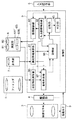
図1は、本発明に係る撮像装置の一実施形態を示すブロック図である。
【0022】
図1に示すように、撮像装置1は、撮像光学系2と、撮像素子3と、駆動部4と、ファインダー5と、入力操作部6と、測光部7と、測距部8と、制御部9とを備える。
【0023】
撮像光学系2は、ズームレンズ及びフォーカスレンズからなる撮影レンズを備えてなり、被写体の光像を撮像素子3に結像するものである。
【0024】
撮像素子3は、例えばCCD(Charge Coupled Device)やCMOS(Complementary Metal−Oxide Semiconductor)等の固体撮像素子からなり、撮像光学系2により結像された被写体の光像を受光して光電変換するものである。
【0025】
駆動部4は、撮像光学系2の撮影レンズを光軸方向に駆動するものである。図示はしないが、駆動部4には、撮影レンズの移動範囲内において光軸方向に複数個のコードパターンが所定ピッチで形成されたエンコード板と、このエンコード板に摺接しながら撮影レンズと一体的に移動するエンコーダブラシとが備えられており、エンコード板上のコードパターンをエンコーダブラシを介して読み取ることで、撮影レンズの位置を検出するようになっている。検出された撮影レンズの位置は、焦点距離の算出に用いられる。
【0026】
ファインダー5は、撮影者が撮影範囲を視認する接眼窓であり、本実施形態では、被写体の光像を該ファインダー5に備えられた光学系を介して撮影者の眼に導くための光学ファインダーである。ファインダー5には、測距範囲を示す指標が設けられており、撮影者がファインダを覗くと、その視標が視認できるようになっている。ファインダー5に被写体の光像が写し出されている場合には、その視標はこの光像と重なって表示される。
【0027】
入力操作部6は、撮像素子3により撮像した画像の記録等を指示する操作を入力するためのシャッターボタン、静止画/動画撮影モードや動体撮影モード等の撮影方法に関するモードを選択する操作を入力するためのモード選択ボタン、撮像倍率を調節する操作を入力するためのズームスイッチ、及び撮像装置1の図略の電源をON/OFFする操作を入力するための電源ボタン等を入力するためのものである。
【0028】
シャッターボタンは、2段階(半押し及び全押し)で押圧操作されるボタンであり、シャッターボタン7が半押しされることで、シャッタースピードの設定等が行われる撮像待機状態に設定され、全押しされることで、例えば撮像素子3への露光を終了するタイミングが指示され、所定の記録媒体(例えばメモリカード)に記録する被写体の光学像が決定される。
【0029】
測光部7は、例えば、測光用光学系と該光学系により結像された光像を撮像する測光センサとを備え、TTL(through the lens)測光方式で被写体輝度を検出するものである。検出された被写体輝度は、露出制御値(絞り開口径とシャッタースピードに対応する撮像素子の露光時間)を決定する際に用いられる。
【0030】
測距部8は、撮像光学系2の光軸と異なる光軸を有し、並列に配置された一対の測距用光学系81,82と、この測距用光学系81,82の略結像面に配置された測距センサ部83とを備えてなり、被写体までの距離(被写体距離)をパッシブ方式により周知技術である三角測距の原理で検出するものである。なお、測距部8は、撮像光学系2の光軸方向の移動に連動して測距用光学系も光軸方向に移動し、撮像倍率の変化に伴って測距範囲が変化するようになっており、ファインダーに設けられた指標で指定される範囲の画像の画素データを用いて被写体距離を検出する。
【0031】
図2は、本実施形態における測距センサ部83の構成を示す図である。
【0032】
図2に示すように、測距センサ部83は、例えばCMOS等の非破壊読み出しの固体撮像素子からなる複数のラインセンサ831〜838と、各ラインセンサ831〜838に対してデータ転送用の駆動信号を生成する図略の制御回路とを備えて構成されている。
【0033】
ラインセンサ831〜838の長手方向をX軸方向、該X軸方向に垂直な方向をY軸方向とすると、ラインセンサ831〜834からなるラインセンサ群837と、ラインセンサ835〜838からなるラインセンサ群838とがX軸方向に隣接して配設されているとともに、各ラインセンサ群837,838において、ラインセンサ831〜834及びラインセンサ835〜838は、それぞれY軸方向に略平行に配設されている。
【0034】
ラインセンサ831〜834からなるラインセンサ群837の撮像面には、測距用光学系81により被写体光像が結像される一方、ラインセンサ835〜838からなるラインセンサ群838の撮像面には、測距用光学系82により被写体光像が結像される。
【0035】
本実施形態の測距センサ部83は、制御部9(詳細には後述する撮像制御部93)により、画素データを出力させる画素を選択することができるとともに、画素データを出力した画素からその画素データを再度出力することができる。
【0036】
制御部9は、例えば制御プログラムを記憶するROMや一時的にデータを記憶するRAMからなる後述の記憶部98が内蔵されたマイクロコンピュータからなり、撮像装置1内の各部の駆動を関連付けて制御するものである。
【0037】
また、制御部9は、機能的に、測光情報演算部91、焦点距離検出部92、撮像制御部93、比較部94、判定部95、測距情報演算部96、駆動制御部97及び記憶部98を備える。
【0038】
測光情報演算部91は、測光部7で得られた測光情報に基づき被写体輝度を算出するものである。この算出された被写体輝度は、測光データとして駆動制御部94に伝送されるとともに、記憶部95に格納される。
【0039】
焦点距離検出部92は、駆動部4において読み取られたコードパターンに基づき、焦点距離を検出するものである。この焦点距離は、焦点距離データとして駆動制御部94及び撮像制御部95に伝送されるとともに、記憶部95に格納される。
【0040】
撮像制御部93は、前述した測距センサ部83の制御回路による駆動信号の出力動作を制御するものであり、本実施形態においては、焦点距離などに応じて、測距用の画素データを出力させる対象の画素を変えている。以下、この点について説明する。
【0041】
図3を参照して、焦点距離に応じて必要な測距範囲について説明する。
【0042】
図3は、撮影レンズがワイド(広角)側の或る位置(以下、ワイド位置という)に位置するとき、該撮影レンズは矢印Aに示す視野角(撮像範囲)を有し、テレ(望遠)側の或る位置(以下、テレ位置という)に位置するとき、矢印Bに示す視野角を有する場合を示している。
【0043】
また、測距部8の測距用光学系81,82は、焦点距離が固定されていて、常に直線▲1▼から直線▲5▼までの範囲の視野角を有し、この視野角内の被写体光像を測距センサ部83の結像面に結像する場合を示している。
【0044】
図3において、撮影レンズをワイド位置及びテレ位置の各位置に位置させて、異なる距離A,B(距離A>距離B)に位置する被写体を撮像する場合(撮像素子3を用いて記録用の画像を得るための撮像を行う場合)について考える。
【0045】
図3から判るように、撮影レンズをワイド位置に位置させて距離Aに位置する被写体を撮像するとき(以下、パターン▲1▼という)には、直線▲1▼から直線▲5▼までの範囲を測距対象とする必要がある。また、このとき、撮影レンズをワイド位置に位置させて被写体を撮像するから焦点距離が短く、焦点深度が比較的深くなり(測距センサ部83側のピントの合う範囲が広くなり)、高い測距精度は要求されない。
【0046】
一方、撮影レンズをテレ位置に位置させて距離Aに位置する被写体を撮像するとき(以下、パターン▲2▼という)には、直線▲2▼から直線▲4▼までの範囲を測距対象とすればよい。また、このとき、撮影レンズをテレ位置に位置させて被写体を撮像するから焦点距離が長く、よって焦点深度が比較的浅くなり(測距センサ部83側のピントの合う範囲が狭くなり)、高い測距精度が要求される。
【0047】
撮影レンズをワイド位置に位置させて距離Bに位置する被写体を撮像するとき(以下、パターン▲3▼という)には、直線▲1▼から直線▲4▼までの範囲を測距対象とする必要がある。また、このとき、パターン▲1▼と同様、撮影レンズをワイド位置に位置させて被写体を撮像するから焦点距離が短く、よって焦点深度が比較的深くなり(測距センサ部83側のピントの合う範囲が広くなり)、高い測距精度は要求されない。
【0048】
一方、撮影レンズをテレ位置に位置させて距離Bに位置する被写体を撮像するとき(以下、パターン▲4▼という)には、直線▲1▼から直線▲3▼までの範囲を測距対象とすればよい。また、このとき、パターン▲2▼と同様、撮影レンズをテレ位置に位置させて被写体を撮像するから焦点距離が長く、焦点深度が比較的浅くなり(測距センサ部83側のピントの合う範囲が狭くなり)、高い測距精度が要求される。
【0049】
このように、パターン▲1▼においては、直線▲1▼から直線▲5▼までの範囲を測距対象とする必要があること、及び高い測距精度は要求されないことから、各ラインセンサ831〜838について、直線▲1▼から直線▲5▼までの測距範囲に対応する画素配設領域全体から、画素データを読み出す対象の画素を所定個おき(本実施形態では1個おき)とすることで画素を間引いて画素データを読み出し、該画素データに基づき測距を行う。
【0050】
また、パターン▲3▼についても同様に、直線▲1▼から直線▲4▼までの範囲を測距対象とする必要があること、及び高い測距精度は要求されないことから、各ラインセンサ831〜838について、直線▲1▼から直線▲4▼までの測距範囲に対応する画素配設領域から、画素データを読み出す対象の画素を所定個おきとすることで画素を間引いて画素データを読み出し、該画素データに基づき測距を行う。
【0051】
一方、パターン▲2▼においては、直線▲2▼から直線▲4▼までの範囲を測距対象とすればよいこと、及び高い測距精度が要求されることから、直線▲2▼から直線▲4▼までの測距範囲に対応する領域内の全ての画素から画素データを読み出し、該画素データに基づき測距を行う。
【0052】
また、パターン▲4▼についても同様に、直線▲1▼から直線▲3▼までの範囲を測距対象とすればよいこと、及び高い測距精度が要求されることから、直線▲1▼から直線▲3▼までの測距範囲に対応する領域内の全ての画素から画素データを読み出し、該画素データに基づき測距を行う。
【0053】
これにより、全てのパターン▲1▼〜▲4▼において、測距演算時間の短縮化と記憶部の記憶容量の低減化を実現するとともに、パターン▲1▼,▲3▼においては広い測距範囲を確保する一方、パターン▲2▼,▲4▼においては測距精度を確保するようにしている。
【0054】
なお、パターン▲1▼,▲3▼の場合のように、画素を間引いて画素データを読み出し、この読み出した画素データに基づいて行う測距を間引き測距といい、特定領域内の全ての画素から画素データを読み出し、この読み出した画素データに基づいて行う測距を全画素測距というものとする。
【0055】
前述したような構成を実現するため、図4に示すように、撮像制御部93は、各ラインセンサ831〜838の画素の画素データ出力動作を制御する。なお、図4は、左右の各ラインセンサ群のうちそれぞれ1のラインセンサのみを図示したものである。
【0056】
図4(a)に示すように、撮像制御部93は、例えば前述の撮影レンズをテレ位置に位置させて撮像するときに対応する、焦点距離が所定の閾値より大きいとき、及び絞り開口径が所定の閾値より大きいときの少なくともいずれか一方に当てはまるとき(焦点深度が浅いとき)には、各ラインセンサ831〜838における中央領域に位置する全ての画素(図4(a)においては6つの画素)から画素データを出力させる。
【0057】
一方、撮像制御部93は、例えば前述の撮影レンズをテレ位置に位置させて撮像するときに対応する、焦点距離及び絞り開口径が各閾値より小さいとき(焦点深度が深いとき)には、次のように処理する。
【0058】
すなわち、この場合には、一旦、測距センサ全体で被写体を撮像して間引き測距を行い、高精度な測距を行う必要があると判断した場合に、ラインセンサの特定領域で全画素測距を行うようにする。
【0059】
これに基づき、撮像制御部93は、図5(a)に示すように、まず、各ラインセンサ831〜838の受光領域を複数のエリア(図5(b)においてはエリア1〜5の5つに分割)に分割した上で、図4(b)に示すように、各エリア1〜5において例えば1画素おきに画素データを出力させる。
【0060】
そして、後述の測距情報演算部96により算出される測距値(被写体距離)が該測距値の閾値より大きい場合(高精度な測距を行う必要があると判断する一条件)には、各ラインセンサ831〜838のうち、主被写体を撮像したエリアを中心とする所定領域の画素を、さらに複数のエリア(このエリアを小エリアという)に分割し、各小エリアにおいて、すべての画素の画素データを出力させる。
【0061】
例えば、図5(b)に示すように、撮像制御部93は、各ラインセンサ831〜838の撮像領域を長手方向に、例えば5つのエリア1〜エリア5に分割し、各エリア1〜5において、例えば1画素おきに画素データを出力させる。そして、測距情報演算部96により、この画素データに基づいて測距値を算出する。
【0062】
その結果、エリア3で撮像された画像の被写体が最も近くに存在し、例えばこの被写体が主被写体であると判断され、その主被写体までの距離が該被写体距離の閾値より大きい場合(主被写体が撮像装置1から比較的遠くに存在し、再度、精度の高い測距が必要と考えられる場合)には、図5(c)に示すように、撮像制御部93は、エリア3に属する全ての画素と、該エリア3に隣接し、エリア2及び4に属する一部の画素とからなる領域を、例えば5つの小エリア1〜5に分割し、各小エリア1〜5において、全ての画素の画素データを出力させる。そして、後述の測距情報演算部96により、この画素データに基づいて測距値が算出される。
【0063】
また、撮像装置1の撮影モードが動体撮影モードに設定されている場合には、前述の間引き測距を複数回実行し、動体が存在するか否かを検出する。
【0064】
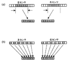
図6(a)は、測距センサ部83の撮像範囲内において、主被写体が手前側に移動する状態を示したもので、図6(b)は、同じく測距センサ部83の撮像範囲内において、主被写体が撮像装置1から略一定の距離を保ったまま移動する状態を示したものである。なお、図6(a),(b)は、それぞれ一方のラインセンサ群のみを示している。
【0065】
また、図7は、ラインセンサ831〜838のうち1のラインセンサ(例えばラインセンサ832)について、画素データを出力させる画素の選択方法を示す図である。
【0066】
図6(a)においては、各ラインセンサ831〜834をそれぞれ5つのエリア(101〜105,201〜205,…,501〜505)に分割した場合において、複数回間引き測距を行った結果、例えばエリア103や303等に対応する測距値が増加したことを検出することで、動体(主被写体)の存在を検出することができる。
【0067】
図6(b)においては、複数回間引き測距を行った結果、略同一の測距値が得られるエリアが例えばエリア102からエリア103に移動したことを検出することで、動体(主被写体)の存在を検出することができる。
【0068】
このように動体が存在するか否かを検出するためには、できるだけ広く測距範囲を確保する必要があるため、図7(a)に示すように、撮像制御部93は、ラインセンサ832の撮像範囲全体から例えば1画素おきに画素(図7(a)における黒塗りの画素)を選択し、この画素から画素データを出力させる。
【0069】
このようにして動体の存在を検出した場合には、図7に示すように、この複数回の間引き測距により算出される各測距値に基づき、各ラインセンサ831〜838の撮像領域の中から動体を含む一部領域を指定し、この領域内の画素から画素データを出力させる。
【0070】
すなわち、図7(b)に示すように、例えばラインセンサ832において、主にエリア203で動体の画像を撮像したものとすると、撮像制御部93は、このエリア203を指定し、このエリア203の画素と、エリア203に隣接するエリア202,204の画素202a,202b,204a,204bを、例えば3つの小エリア1〜3に分割し、各小エリア1〜3の全ての画素から画素データを出力させる。
【0071】
これにより、ラインセンサ832において動体を撮像した領域がより高精度に特定され、被写体距離が高精度に算出される。
【0072】
比較部94は、焦点距離、絞り開口径及び被写体距離がそれぞれ予め設定された閾値より大きいか否かを比較するものである。
【0073】
判定部95は、焦点距離及び絞り開口径が各閾値より小さい場合に、間引き測距の後、被写体距離が閾値より大きいか否かに応じて全画素測距を行う必要があるか否かを判定するものである。
【0074】
測距情報演算部96は、測距部8から得られた測距値に係る情報(測距情報)に基づき、測距値(被写体距離)を算出し、この測距値についての情報を測距データとして駆動制御部97に伝送するものである。
【0075】
駆動制御部97は、測光情報演算部91から伝送された測光データから露出制御値を決定し、この露出制御値に基づく撮像素子3の露出制御を行うとともに、測距情報演算部91から伝送された測距データから撮影レンズの駆動量を算出し、撮影レンズの合焦動作等を行うものである。
【0076】
記憶部98は、測光情報演算部91により算出された測光データ、焦点距離検出部92により検出された焦点距離についての情報、測距情報演算部96により算出された測距データ、駆動制御部97により導出された露出制御値についての情報を記憶するものである。
【0077】
次に、本実施形態の撮像装置1における測距処理を、図8,9に示すフローチャートにしたがって説明する。
【0078】
図8,9に示すように、まず、撮影モード(例えば、静止画/動画撮影モードや動体撮影モードなど)が設定され(ステップS1)、ズームスイッチにより撮像倍率を変更する操作が入力される(ステップS2でYES)と、駆動部4は、撮影レンズをその操作に応じた方向に光軸に沿って駆動し(ステップS3)、焦点距離検出部92は、焦点距離を検出する(ステップS4)。
【0079】
また、ズームスイッチの操作が解除され、シャッターボタンが半押しされる(ステップS2でNO,S5でYES)と、測光部7及び測光情報演算部91は、測光を行って被写体輝度を検出し、露出制御値を決定する(ステップS6)。
【0080】
次いで、ステップS4で検出された焦点距離が閾値以下の場合(ステップS7でNO)、及びステップS6で決定された絞り開口径が閾値以下の場合(ステップS8でNO)には、撮像制御部93は、ステップS1で動体撮影モードが設定されているか否かを判断し(ステップS9)、動体撮影モードが設定されている場合(ステップS9でYES)には、図7(a)に示すように間引き測距を2回以上行い(ステップS10)、動体撮影モードが設定されていない場合(ステップS9でNO)には、図4(a)に示すように間引き測距を1回行う(ステップS11)。ここでは、主被写体(動体を含む)を検出するために広い範囲を測距対象とする必要があること、及び高い測距精度は要求されないことから、間引き測距を行っている。
【0081】
そして、ステップS10又はS11の処理により得られた測距値が閾値より小さい場合(ステップS12でNO)であって、ステップS10の処理の結果、測距情報演算部96により動体(主被写体)が検出されない場合(ステップS13でNO)には、撮影レンズに対し焦点調節用の駆動を行うための測距値を、ステップS10又はS11で算出された測距値に決定する(ステップS14)。
【0082】
一方、焦点距離が閾値を超える場合(ステップS7でYES)、及び絞り開口径が閾値を超える場合(ステップS8でYES)には、前述のように測距範囲を狭めることができること、及び高精度で測距を行う必要があることから、前述のパターン▲2▼やパターン▲4▼のように、撮像制御部93は、図4(a)のようにラインセンサ831〜838のうち測距の対象とする範囲を限定して設定し(ステップS15)、この測距範囲に対応する領域内の全ての画素から画素データを読み出して、測距情報演算部96は、該画素データに基づき測距を行う(ステップS16,S17)。
【0083】
また、測距値が閾値より大きい場合(ステップS12でYES)、及び動体を検出した場合(ステップS13でYES)にも、主被写体をほぼ特定し、凡その被写体距離は算出できているが、更なる高精度な測距を行う必要があることから、撮像制御部93は、図5(b)や図7(c)のように、ラインセンサ831〜838のうち測距の対象とする範囲を限定して設定し(ステップS15)、この測距範囲に対応する領域内の全ての画素から画素データを読み出して、測距情報演算部96は、該画素データに基づき測距を行う(ステップS16,S17)。
【0084】
ステップS14又はS17で測距値が決定すると、駆動制御部97は、その測距値に基づいて撮影レンズの焦点調節を行い(ステップS18)、シャッターボタンが全押しされる(ステップS19)と、撮像素子3は露光動作を行う(ステップS20)。
【0085】
このように、焦点距離及び絞り開口径が小さい場合、すなわち焦点深度が深い場合には、広い範囲を測距対象として間引き測距を行うようにしたので、主被写体をより確実に検出することができるとともに、測距センサ部83の全ての画素から得られる画素データを用いて測距を行う構成に比して、測距演算時間を短縮化し、且つ測距用の画素データを記憶する記憶部98の記憶容量を低減化することができる。
【0086】
また、焦点距離や絞り開口径が大きい場合、すなわち焦点深度が浅い場合には、各ラインセンサ831〜838のうち一部の領域を指定し、その領域に位置する全ての画素の画素データを用いて全画素測距を行うようにしたので、高精度な測距を行うことができるとともに、測距センサ部83の全ての画素から得られる画素データを用いて測距を行う構成に比して、測距演算時間を短縮化し、且つ測距用の画素データを記憶する記憶部98の記憶容量を低減化することができる。
【0087】
また、焦点深度が深い場合であっても、間引き測距の結果、被写体距離が大きい場合(主被写体が撮像装置1から遠くに離れている場合)や、主被写体が動体である場合にも全画素測距を行うようにしたので、高精度な測距を行うことができる。
【0088】
また、焦点深度が深い場合であって、被写体距離が小さく、且つ主被写体が動体でない場合には、撮影レンズを焦点調節用に駆動するための測距値を、間引き測距により得られる測距値としたので、測距センサ部83の全ての画素から得られる画素データを用いて測距を行う構成に比して、測距演算時間を短縮化し、且つ測距用の画素データを記憶する記憶部98の記憶容量を低減化することができる。
【0089】
また、測距センサ部83を構成する固体撮像素子としてCMOSを使用し、画素データを出力した画素からその画素データを再度出力することができるようにしたので、測距センサ部83による一回の積分で、間引き測距と全画素測距との両方を行うことができる。
【0090】
また、測距部8を、ファインダーに設けられた指標で指定される範囲の画像の画素データを用いて被写体距離を検出するように構成したので、焦点距離に応じた適切な被写体距離の算出を行うことができる。
【0091】
なお、本発明は、上記実施形態に限らず、次の変形形態(1)〜(3)が採用可能である。
(1)撮像素子の形態は、図2に示すような、複数のラインセンサ831〜838により構成されるものに限らず、例えば図10に示すように、X軸方向及びY軸方向に複数の画素が隣接して配置された1対のエリアセンサでもよい。
【0092】
この場合、エリアセンサを、X方向に延びる複数ラインセンサがY軸方向に隣接して配置されているものとして捉えることで、測距センサ部83と同様に、本発明を適用することができる。
(2)上記実施形態では、焦点深度が深い場合に、広い範囲を測距対象として間引き測距を行うようにしたが、これに限らず、焦点距離や焦点深度に関係なくまず間引き測距を行い、その測距結果と焦点深度とに応じて、全画素測距を行うようにしてもよい。
(3)上記実施形態では、測距センサ部83を構成する固体撮像素子としてCMOSを使用したが、これに限らず、CCD(Charge Coupled Device)等の破壊読み出しの撮像素子(画素から画素データを読み出すと、再度その画素から同一の画素データを読み出すことができない撮像素子)を用いてもよい。
【0093】
この場合、一旦、全ての画素から画素データを取り込んだ後、必要な画素データ(上記実施形態では、1画素おきにラインセンサ831〜838から読み出した画素データに対応する)のみを記憶部98に記憶させ、この記憶した画素データに基づき測距を行うようにするとよい。
【0094】
以上、説明した撮像装置は、以下の付記1〜7に示す発明を主に含む。
【0095】
[付記1] 被写体の光像を撮像する撮像素子と、焦点調節を行う機能を備え、前記撮像素子の撮像面に前記被写体の光像を結像する撮像光学系とを備える撮像装置であって、複数の測距用光学系と、前記各測距用光学系に対応して備えられ、少なくとも一方向に配置された複数の画素からなる複数の測距センサと、前記各測距センサにおいて、所定数の画素置きに複数の画素を指定し、この画素から得られる画素データに基づいて被写体距離を算出する第1の測距部と、前記各測距センサにおいて、一部の撮像領域を指定し、この撮像領域内の全ての画素から得られる画素データに基づいて被写体距離を算出する第2の測距部と、設定される撮像条件に応じて、前記第1の測距部または第2の測距部のいずれを動作させるかを選択する選択部と、前記選択された測距部により算出される被写体距離に基づき、前記撮像光学系に焦点調節を行わせる駆動部とを備えることを特徴とする撮像装置。
【0096】
[付記2] 被写体の明るさに基づき前記撮像素子についての露出制御値を設定する手段を備えるとともに、前記撮像光学系は焦点距離が変更可能に構成されてなり、前記撮像条件は、前記撮像光学系の焦点距離又は露出制御値によって変化する焦点深度についての情報であり、前記選択部は、前記焦点深度の大きさに応じて前記第1、第2の測距部の一方を選択することを特徴とする付記1に記載の撮像装置。
【0097】
[付記3] 前記選択手段は、前記焦点深度が該焦点深度についての閾値より小さいとき、前記第1の測距手段を選択し、前記焦点深度が該焦点深度についての閾値より大きいとき、前記第2の測距手段を選択することを特徴とする付記2に記載の撮像装置。
【0098】
この発明によれば、前記焦点深度が該焦点深度についての閾値より小さいときには、第1の測距部を選択することで、広い範囲を測距対象として、被写体を確実に検出することができるとともに、各測距センサの全ての画素から得られる画素データを用いて測距を行う構成に比して、測距演算時間を短縮化し、且つ測距用の画素データを記憶する記憶部の記憶容量を低減化することができる。
【0099】
また、前記焦点深度が該焦点深度についての閾値より大きいときには、第2の測距部を選択することで、測距の高い精度を確保することができるとともに、各測距センサの全ての画素から得られる画素データを用いて測距を行う構成に比して、測距演算時間を短縮化し、且つ測距用の画素データを記憶する記憶部の記憶容量を低減化することができる。
【0100】
[付記4] 前記撮像素子の撮像範囲を視認するためのファインダーを有し、前記第2の測距部は、前記ファインダーに設けられた測距範囲を示す指標で指定される画像の画素データを用いて被写体距離を算出することを特徴とする付記1ないし3のいずれかに記載の撮像装置。
【0101】
[付記5] 前記第1の測距部による被写体距離の算出後、この算出結果又は/及び設定される撮像条件に基づき、前記第2の測距部による被写体距離の算出を行うか否かを判定する判定部を備え、前記第2の測距部は、前記判定部により第2の測距部による被写体距離の算出を行うものと判定されると、前記第1の測距部により算出された被写体距離に基づき、各測距センサにおいて一部の撮像領域を指定し、この撮像領域内の全ての画素から得られる画素データに基づいて被写体距離を算出することを特徴とする付記1ないし4のいずれかに記載の撮像装置。
【0102】
[付記6] 前記第1の測距部は、被写体距離の算出を複数回実行し、前記判定部は、前記第1の測距部による算出結果に基づき被写体が動体であることが検出されると、第2の測距部による被写体距離の算出を行うものと判定することを特徴とする付記5に記載の撮像装置。
【0103】
[付記7] 前記第2の測距部により指定される前記一部の撮像領域は、前記測距センサの中央側の撮像領域であることを特徴とする付記1ないし6のいずれかに記載の撮像装置。
【0104】
この発明によれば、第2の測距部により指定される前記一部の撮像領域は、前記測距センサの中央側の撮像領域としたので、主被写体が存在する可能性が高いと考えられる測距センサの中央側で該主被写体を撮像することにより、主被写体までの距離を正確に算出することができる。
【0105】
【発明の効果】
本発明によれば、各測距センサにおいて、所定数の画素置きに複数の画素を指定し、この画素から得られる画素データに基づいて被写体距離を算出する第1の測距部と、前記各測距センサにおいて、一部の撮像領域を指定し、この撮像領域内の全ての画素から得られる画素データに基づいて被写体距離を算出する第2の測距部とを備え、選択部により、焦点深度の大きさに応じて前記第1、第2の測距部の一方を選択するようにしたので、各測距センサの全ての画素から得られる画素データを用いて測距を行う構成に比して、測距演算時間を短縮化し、且つ測距用の画素データを記憶する記憶部の記憶容量を低減化することができる。
【0106】
また、本発明によれば、第2の測距部は、ファインダーに設けられた測距範囲を示す指標で指定される画像の画素データを用いて被写体距離を算出するように構成したので、焦点距離に応じて適切に被写体距離を算出することができる。
【0107】
本発明によれば、第1の測距部による被写体距離の算出後、この算出結果又は/及び前記設定される撮像条件に基づき、第2の測距部による被写体距離の算出を行うか否かを判定し、第2の測距部による被写体距離の算出を行うものと判定されると、第2の測距部により、前記第1の測距部により算出された被写体距離に基づき、各測距センサにおいて一部の撮像領域を指定し、この撮像領域内の全ての画素から得られる画素データに基づいて被写体距離を算出するようにしたので、第1の測距部より高精度に被写体距離を算出することが必要な場合に、第2の測距部によって被写体距離を算出することで、より正確な被写体距離を得ることができる。
【0108】
また、本発明によれば、第1の測距部により、被写体距離の算出を複数回実行し、判定部は、前記第1の測距部による算出結果に基づき被写体が動体であることが検出されると、第2の測距部による被写体距離の算出を行うものと判定するようにしたので、第1の測距部による被写体距離の算出の結果、被写体が動体であることが判明したときに、第2の測距部によって被写体距離を算出することで、より正確な被写体距離を得ることができる。
【図面の簡単な説明】
【図1】本発明の実施形態に係る撮像装置のブロック図である。
【図2】本実施形態における測距センサ部の構成を示す図である。
【図3】焦点距離に応じて必要な測距範囲を説明するための図である。
【図4】間引き測距と全画素測距を説明するための図である。
【図5】間引き測距と全画素測距を説明するための図である。
【図6】動体撮影モードにおいて動体を検出する方法を説明するための図である。
【図7】動体撮影モードにおける間引き測距と全画素測距を説明するための図である。
【図8】撮像装置における測距処理を示すフローチャートである。
【図9】撮像装置における測距処理を示すフローチャートである。
【図10】測距センサ部の他の構成を示す図である。
【符号の説明】
1 撮像装置
2 撮像光学系
3 撮像素子
4 駆動部
5 ファインダー
6 入力操作部
7 測光部
8 測距部
81,82 測距用光学系
83 測距センサ部
831〜838 ラインセンサ
91 測光情報演算部
92 焦点距離検出部
93 撮像制御部
94 比較部
95 判定部
96 測距情報演算部
97 駆動制御部
98 記憶部
9 制御部[0001]
TECHNICAL FIELD OF THE INVENTION
The present invention relates to an image pickup apparatus such as a digital camera, a silver halide camera, and a video camera provided with a distance measuring device that measures a subject distance using an image pickup device.
[0002]
[Prior art]
For example, it has a plurality of optical systems and an image sensor provided corresponding to each optical system, receives a light image formed through each optical system by each image sensor, and performs a photoelectric conversion operation ( Imaging devices are widely known, which are equipped with a distance measuring device that calculates a shift amount of an image forming position of each optical image based on an output from an image sensor and measures a distance to a subject from the position shift amount. (For example,
[0003]
In this type of imaging apparatus, in order to accurately measure the distance to the main subject (distance measurement), it is necessary to reliably detect the main subject in the shooting range.
[0004]
In order to reliably detect the main subject in the photographing range, the image sensor is constituted by a plurality of line sensors, and the plurality of line sensors are arranged in a predetermined direction in a direction perpendicular to the arrangement direction of the pixels of each line sensor. In some cases, the distance measuring device may be configured to capture an image in the photographing range as wide as possible by arranging the line sensors at intervals and increasing the number of pixels to form each line sensor to be long.
[0005]
[Patent Document 1]
JP-A-9-213315
[0006]
[Problems to be solved by the invention]
However, if the line sensor is formed long by increasing the number of pixels, and the distance measurement is performed using the pixel signals obtained from almost all the pixels, the pixel signal increases as the number of pixels increases. In addition, the calculation time required for distance measurement using the pixel signal increases, and for example, the storage capacity of a memory for temporarily storing the pixel signal needs to be increased in order to perform the calculation.
[0007]
Also, if the number of line sensors is reduced and the distance between adjacent line sensors is increased to suppress this increase in pixel signals, the distance to a non-main subject is incorrectly regarded as the distance to the main subject. Therefore, there is a problem that accurate distance measurement becomes difficult.
[0008]
The present invention has been made in view of the above, and an object of the present invention is to provide an imaging device capable of performing accurate distance measurement while preventing an increase in calculation time and memory capacity required for distance measurement. I do.
[0009]
[Means for Solving the Problems]
The invention according to
[0010]
According to the present invention, a light image of a subject is received by each distance measuring sensor via the corresponding distance measuring optical system. Then, the selection unit selects which of the first distance measurement unit and the second distance measurement unit is operated in accordance with the set imaging condition. When the first distance measuring unit is selected by the selecting unit, a plurality of pixels are designated at every predetermined number of pixels in each distance measuring sensor, and a subject distance is calculated based on pixel data obtained from the pixels. Is done. On the other hand, when the second distance measurement unit is selected by the selection unit, a part of the imaging region is specified in each distance measurement sensor, and based on pixel data obtained from all the pixels in the imaging region. The subject distance is calculated. Then, the focus adjustment by the imaging optical system is controlled by the driving unit based on the subject distance calculated by the selected distance measuring unit.
[0011]
According to a second aspect of the present invention, there is provided the image pickup apparatus according to the first aspect, further comprising a unit configured to set an exposure control value for the image sensor based on brightness of a subject, and a focal length of the imaging optical system is changed. The imaging condition is information on a depth of focus that changes according to a focal length or an exposure control value of the imaging optical system, and the selection unit is configured to perform the second imaging in accordance with the magnitude of the depth of focus. One of the first and second distance measuring units is selected.
[0012]
According to this invention, the selector selects one of the first and second distance measuring units according to the depth of focus. Therefore, for example, when the depth of focus is deep, by selecting the first distance measuring unit, it is possible to reliably detect a subject with a wide range as a distance measuring target, and to detect all pixels of each distance measuring sensor. As compared with the configuration in which the distance measurement is performed using the pixel data obtained from the above, the distance measurement operation time can be reduced, and the storage capacity of the storage unit that stores the pixel data for the distance measurement can be reduced.
[0013]
Further, when the depth of focus is shallow, by selecting the second ranging unit, it is possible to secure high ranging accuracy, and to use pixel data obtained from all pixels of each ranging sensor. As compared with the configuration in which distance measurement is performed, the distance measurement calculation time can be reduced, and the storage capacity of the storage unit that stores the pixel data for distance measurement can be reduced.
[0014]
According to a third aspect of the present invention, in the imaging device according to the first or second aspect, the imaging apparatus further includes a finder for visually recognizing an imaging range of the imaging element, and the second distance measurement unit is provided in the finder. The subject distance is calculated using pixel data of an image specified by an index indicating the obtained distance measurement range.
[0015]
According to the present invention, the second distance measuring unit is configured to calculate the subject distance using the pixel data of the image specified by the index indicating the distance measurement range provided in the finder, so that the focal length Accordingly, the subject distance can be appropriately calculated.
[0016]
According to a fourth aspect of the present invention, in the imaging apparatus according to any one of the first to third aspects, after calculating the subject distance by the first distance measuring unit, the calculation result or / and the set imaging condition are set. A determination unit that determines whether to calculate a subject distance by the second distance measurement unit based on the determination of the subject distance by the second distance measurement unit by the determination unit. If it is determined that the calculation is to be performed, a part of the imaging area is designated in each distance measurement sensor based on the subject distance calculated by the first distance measurement unit, and the image is obtained from all the pixels in the imaging area. The object distance is calculated based on the pixel data obtained.
[0017]
According to this invention, after the calculation of the subject distance by the first distance measuring unit, the determining unit calculates the subject distance by the second distance measuring unit based on the calculation result and / or the set imaging condition. It is determined whether or not to perform the calculation. If the determination unit determines that the subject distance is to be calculated by the second ranging unit, the second ranging unit determines the first ranging unit. A part of the imaging area is designated in each distance measurement sensor based on the subject distance calculated by, and the subject distance is calculated based on pixel data obtained from all the pixels in the imaging area.
[0018]
Therefore, when it is necessary to calculate the subject distance with higher accuracy than the first distance measurement unit, for example, when it is determined that the subject distance is large as a result of the calculation of the subject distance by the first distance measurement unit, By calculating the subject distance by the second ranging unit, a more accurate subject distance can be obtained.
[0019]
According to a fifth aspect of the present invention, in the imaging device according to the fourth aspect, the first distance measuring unit executes the calculation of the subject distance a plurality of times, and the determining unit determines the first distance measuring unit. When it is detected that the subject is a moving object based on the calculation result by (1), it is determined that the subject distance is to be calculated by the second distance measuring unit.
[0020]
According to the present invention, the subject distance is calculated a plurality of times by the first distance measuring unit, and when it is detected that the subject is a moving object based on the calculation result, the determining unit performs the second distance measuring. It is determined that the subject distance is calculated by the second distance measuring unit when it is determined that the subject is a moving object as a result of calculating the subject distance by the first distance measuring unit. By calculating the subject distance, a more accurate subject distance can be obtained.
[0021]
BEST MODE FOR CARRYING OUT THE INVENTION
FIG. 1 is a block diagram illustrating an embodiment of an imaging device according to the present invention.
[0022]
As shown in FIG. 1, the
[0023]
The imaging
[0024]
The
[0025]
The
[0026]
The
[0027]
The
[0028]
The shutter button is a button that is pressed in two steps (half-press and full-press). When the
[0029]
The
[0030]
The
[0031]
FIG. 2 is a diagram illustrating a configuration of the distance measuring
[0032]
As shown in FIG. 2, the distance measuring
[0033]
Assuming that a longitudinal direction of the
[0034]
A subject light image is formed on the imaging surface of the
[0035]
The distance
[0036]
The
[0037]
Further, the
[0038]
The photometry
[0039]
The
[0040]
The
[0041]
With reference to FIG. 3, the necessary distance measurement range according to the focal length will be described.
[0042]
FIG. 3 shows that when the taking lens is located at a certain position on the wide (wide-angle) side (hereinafter, referred to as a wide position), the taking lens has a viewing angle (imaging range) indicated by an arrow A and is tele (telephoto). When the camera is located at a certain position on the side (hereinafter referred to as a telephoto position), it has a viewing angle indicated by an arrow B.
[0043]
The distance measuring
[0044]
In FIG. 3, when the photographing lens is positioned at each of the wide position and the telephoto position to capture an image of a subject located at different distances A and B (distance A> distance B) (for recording using the image sensor 3). (In the case of performing imaging for obtaining an image).
[0045]
As can be seen from FIG. 3, when the photographing lens is located at the wide position and an image of the subject located at the distance A is taken (hereinafter referred to as a pattern (1)), the range from the straight line (1) to the straight line (5) is obtained. Needs to be measured. Also, at this time, since the imaging lens is positioned at the wide position to capture an image of the subject, the focal length is short, the depth of focus is relatively deep (the focusing range on the distance measuring
[0046]
On the other hand, when the imaging lens is positioned at the telephoto position and an image of the subject located at the distance A is taken (hereinafter referred to as a pattern (2)), the range from the straight line (2) to the straight line (4) is set as the distance measurement target. do it. Also, at this time, since the imaging lens is positioned at the telephoto position to capture the image of the subject, the focal length is long, and therefore the depth of focus is relatively shallow (the focusing range on the distance measuring
[0047]
When taking an image of a subject located at a distance B by positioning the taking lens at the wide position (hereinafter referred to as a pattern (3)), the range from the straight line (1) to the straight line (4) needs to be the distance measurement target. There is. Further, at this time, as in the case of the pattern (1), the photographing lens is positioned at the wide position and the subject is imaged, so that the focal length is short, and the focal depth is relatively deep (the focus on the distance measuring
[0048]
On the other hand, when the photographing lens is positioned at the telephoto position and an image of a subject located at a distance B is taken (hereinafter referred to as a pattern {circle around (4)}), the range from the straight line {circle around (1)} to the straight line {circle around (3)} is regarded as the distance measurement target. do it. Also, at this time, as in the case of the pattern (2), the imaging lens is positioned at the tele position to image the subject, so that the focal length is long and the depth of focus is relatively shallow (the focusing range on the side of the distance measuring sensor unit 83). Becomes narrower), and high ranging accuracy is required.
[0049]
As described above, in the pattern (1), since the range from the straight line (1) to the straight line (5) needs to be measured, and high ranging accuracy is not required, each
[0050]
Similarly, for the pattern (3), since the range from the straight line (1) to the straight line (4) needs to be measured, and high ranging accuracy is not required, each
[0051]
On the other hand, in the pattern (2), the range from the straight line (2) to the straight line (4) may be set as the object of distance measurement, and a high distance measurement accuracy is required. Pixel data is read from all the pixels in the area corresponding to the distance measurement range up to 44, and distance measurement is performed based on the pixel data.
[0052]
Similarly, for the pattern (4), the range from the straight line (1) to the straight line (3) may be set as the object of distance measurement, and high distance measurement accuracy is required. Pixel data is read from all the pixels in the area corresponding to the distance measurement range up to the straight line (3), and distance measurement is performed based on the pixel data.
[0053]
As a result, in all of the patterns (1) to (4), shortening of the distance measurement operation time and reduction of the storage capacity of the storage unit are realized, and in the patterns (1) and (3), a wide distance measurement range is obtained. While the distance measurement accuracy is ensured in the patterns (2) and (4).
[0054]
As in the case of the patterns (1) and (3), pixel data is read out by thinning out pixels, and a distance measurement performed based on the read pixel data is called a thinning distance measurement. The pixel data is read from the pixel data, and the distance measurement performed based on the read pixel data is referred to as all pixel distance measurement.
[0055]
In order to realize the above-described configuration, the
[0056]
As shown in FIG. 4A, the
[0057]
On the other hand, when the focal length and the aperture opening diameter are smaller than the respective thresholds (when the depth of focus is deep) corresponding to, for example, the case where the above-described photographing lens is positioned at the telephoto position and performs imaging, the
[0058]
That is, in this case, once it is determined that it is necessary to image the subject with the entire distance measurement sensor and perform thinning distance measurement and perform high-precision distance measurement, all pixel measurement is performed in a specific area of the line sensor. Make a distance.
[0059]
Based on this, as shown in FIG. 5A, the
[0060]
When the distance value (subject distance) calculated by the distance
[0061]
For example, as illustrated in FIG. 5B, the
[0062]
As a result, the subject of the image captured in the
[0063]
When the shooting mode of the
[0064]
FIG. 6A shows a state in which the main subject moves to the near side within the imaging range of the distance
[0065]
FIG. 7 is a diagram illustrating a method of selecting a pixel for outputting pixel data for one of the
[0066]
In FIG. 6A, when each of the
[0067]
In FIG. 6B, a moving object (main subject) is detected by detecting that an area in which substantially the same distance measurement value is obtained has moved from, for example, the
[0068]
In order to detect whether a moving object is present or not, it is necessary to secure a distance measurement range as wide as possible. Therefore, as shown in FIG. For example, every other pixel (a black pixel in FIG. 7A) is selected from the entire imaging range, and pixel data is output from this pixel.
[0069]
When the presence of the moving object is detected in this manner, as shown in FIG. 7, based on each distance measurement value calculated by the plurality of thinning-out distance measurement, the image pickup area of each
[0070]
That is, as shown in FIG. 7B, for example, assuming that the image of the moving object is mainly captured in the
[0071]
As a result, the area where the moving object is imaged by the
[0072]
The
[0073]
When the focal length and the aperture opening diameter are smaller than the respective thresholds, the
[0074]
The ranging
[0075]
The
[0076]
The
[0077]
Next, the distance measurement process in the
[0078]
As shown in FIGS. 8 and 9, first, a shooting mode (for example, a still image / movie shooting mode or a moving object shooting mode) is set (step S1), and an operation for changing the imaging magnification by a zoom switch is input (step S1). When YES in step S2), the
[0079]
When the operation of the zoom switch is released and the shutter button is half-pressed (NO in step S2, YES in S5), the
[0080]
Next, when the focal length detected in step S4 is equal to or smaller than the threshold (NO in step S7), and when the aperture diameter determined in step S6 is equal to or smaller than the threshold (NO in step S8), the
[0081]
If the distance measurement value obtained by the processing in step S10 or S11 is smaller than the threshold (NO in step S12), as a result of the processing in step S10, the moving object (main subject) is determined by the distance measurement
[0082]
On the other hand, when the focal length exceeds the threshold value (YES in step S7), and when the aperture diameter exceeds the threshold value (YES in step S8), it is possible to narrow the distance measurement range as described above, and high accuracy Since the distance measurement needs to be performed, the
[0083]
Also, when the distance measurement value is larger than the threshold value (YES in step S12) and when a moving object is detected (YES in step S13), the main subject is almost specified, and the approximate subject distance can be calculated. Since the distance measurement needs to be performed with higher accuracy, the
[0084]
When the distance measurement value is determined in step S14 or S17, the
[0085]
As described above, when the focal length and the aperture opening diameter are small, that is, when the depth of focus is deep, the thinning-out distance measurement is performed with the wide range as the object to be measured, so that the main subject can be more reliably detected. A storage unit for shortening distance calculation time and storing pixel data for distance measurement as compared with a configuration in which distance measurement is performed using pixel data obtained from all pixels of the distance
[0086]
When the focal length or the aperture opening diameter is large, that is, when the depth of focus is shallow, a partial area is designated among the
[0087]
Even when the depth of focus is deep, even if the subject distance is large (if the main subject is far away from the imaging device 1) or if the main subject is a moving object as a result of the thinning-out ranging, Since pixel distance measurement is performed, highly accurate distance measurement can be performed.
[0088]
When the depth of focus is deep, the subject distance is small, and the main subject is not a moving object, a distance measurement value for driving the taking lens for focus adjustment is obtained by thinning-out distance measurement. Since the value is set as the value, the distance measurement operation time is shortened and the pixel data for distance measurement is stored as compared with a configuration in which distance measurement is performed using pixel data obtained from all pixels of the distance
[0089]
In addition, since CMOS is used as a solid-state image pickup device constituting the distance measuring
[0090]
Further, since the
[0091]
The present invention is not limited to the above embodiment, and the following modifications (1) to (3) can be adopted.
(1) The form of the image sensor is not limited to the one configured by the plurality of
[0092]
In this case, the present invention can be applied similarly to the distance measuring
(2) In the above embodiment, when the depth of focus is deep, thinning-out ranging is performed with a wide range as the object to be measured. However, the present invention is not limited to this. First, thinning-out ranging is performed regardless of the focal length and the focal depth. Alternatively, all pixel ranging may be performed according to the ranging result and the depth of focus.
(3) In the above embodiment, the CMOS is used as the solid-state imaging device constituting the distance measuring
[0093]
In this case, after the pixel data is once fetched from all the pixels, only the necessary pixel data (corresponding to the pixel data read from the
[0094]
The imaging apparatus described above mainly includes the inventions described in the following
[0095]
[Supplementary Note 1] An imaging apparatus, comprising: an imaging device that captures an optical image of a subject; and an imaging optical system that has a function of performing focus adjustment and that forms an optical image of the subject on an imaging surface of the imaging device. A plurality of distance measurement optical systems, a plurality of distance measurement sensors comprising a plurality of pixels arranged in at least one direction, provided in correspondence with each of the distance measurement optical systems, and each of the distance measurement sensors, A first distance measurement unit that specifies a plurality of pixels at every predetermined number of pixels and calculates a subject distance based on pixel data obtained from the pixels, and specifies a part of an imaging area in each of the distance measurement sensors Then, a second distance measuring unit that calculates a subject distance based on pixel data obtained from all pixels in the imaging region, and the first distance measuring unit or the second distance measuring unit according to a set imaging condition. Selection unit to select which of the distance measurement units to operate And a drive unit that causes the imaging optical system to perform focus adjustment based on the subject distance calculated by the selected distance measurement unit.
[0096]
[Supplementary Note 2] The apparatus further includes means for setting an exposure control value for the image sensor based on the brightness of a subject, and the imaging optical system is configured to be capable of changing a focal length. Information on the focal depth that changes according to the focal length of the system or the exposure control value, wherein the selecting unit selects one of the first and second distance measuring units according to the magnitude of the focal depth. An imaging device according to
[0097]
[Supplementary Note 3] The selection unit selects the first distance measurement unit when the depth of focus is smaller than a threshold value for the depth of focus, and selects the first distance measurement unit when the depth of focus is larger than the threshold value for the depth of focus. 3. The imaging apparatus according to
[0098]
According to the present invention, when the depth of focus is smaller than the threshold value for the depth of focus, by selecting the first distance measuring unit, it is possible to reliably detect a subject in a wide range as a distance measurement target. Compared with a configuration in which distance measurement is performed using pixel data obtained from all pixels of each distance measurement sensor, a storage capacity of a storage unit for shortening distance calculation time and storing pixel data for distance measurement Can be reduced.
[0099]
Further, when the depth of focus is larger than the threshold value for the depth of focus, by selecting the second ranging unit, high accuracy of ranging can be ensured, and from all pixels of each ranging sensor, Compared with a configuration in which distance measurement is performed using the obtained pixel data, it is possible to shorten the distance calculation time and reduce the storage capacity of the storage unit that stores the pixel data for distance measurement.
[0100]
[Supplementary Note 4] A finder for visually recognizing an imaging range of the imaging element is provided, and the second distance measurement unit converts pixel data of an image specified by an index indicating a distance measurement range provided in the finder. The imaging apparatus according to any one of
[0101]
[Supplementary Note 5] After calculating the subject distance by the first distance measuring unit, it is determined whether or not to calculate the subject distance by the second distance measuring unit based on the calculation result or / and the set imaging condition. When the determination unit determines that the second distance measuring unit calculates the subject distance, the second distance measuring unit is calculated by the first distance measuring unit. A part of the imaging area is designated in each distance measuring sensor based on the subject distance, and the subject distance is calculated based on pixel data obtained from all the pixels in the imaging area. An imaging device according to any one of the above.
[0102]
[Supplementary Note 6] The first distance measurement unit performs the calculation of the subject distance a plurality of times, and the determination unit detects that the subject is a moving object based on the calculation result by the first distance measurement unit. 6. The imaging apparatus according to
[0103]
[Supplementary Note 7] The image forming apparatus according to any one of
[0104]
According to the present invention, the partial imaging region specified by the second distance measurement unit is the imaging region on the center side of the distance measurement sensor, so it is considered that there is a high possibility that the main subject exists. By imaging the main subject on the center side of the distance measurement sensor, the distance to the main subject can be accurately calculated.
[0105]
【The invention's effect】
According to the present invention, in each distance measuring sensor, a plurality of pixels are designated every predetermined number of pixels, and a first distance measuring unit that calculates a subject distance based on pixel data obtained from the pixels; A second distance measuring unit for designating a part of the imaging region in the distance measuring sensor and calculating a subject distance based on pixel data obtained from all pixels in the imaging region; Since one of the first and second distance measurement units is selected according to the depth, a distance measurement is performed in comparison with a configuration in which distance measurement is performed using pixel data obtained from all pixels of each distance measurement sensor. As a result, the distance measurement operation time can be reduced, and the storage capacity of the storage unit that stores the pixel data for distance measurement can be reduced.
[0106]
Further, according to the present invention, the second distance measuring unit is configured to calculate the subject distance using the pixel data of the image specified by the index indicating the distance measurement range provided in the finder, so The subject distance can be appropriately calculated according to the distance.
[0107]
According to the present invention, after calculating the object distance by the first distance measuring unit, whether or not to calculate the object distance by the second distance measuring unit based on the calculation result or / and the set imaging condition is determined. Is determined, and when it is determined that the subject distance is calculated by the second distance measuring unit, each of the distances is measured by the second distance measuring unit based on the object distance calculated by the first distance measuring unit. Since a part of the imaging area is specified in the distance sensor, and the object distance is calculated based on the pixel data obtained from all the pixels in the imaging area, the object distance can be calculated with higher accuracy than the first distance measurement unit. When it is necessary to calculate the subject distance, a more accurate subject distance can be obtained by calculating the subject distance by the second distance measuring unit.
[0108]
Further, according to the present invention, the subject distance is calculated a plurality of times by the first distance measuring unit, and the determining unit detects that the subject is a moving object based on the calculation result by the first distance measuring unit. Then, it is determined that the subject distance is to be calculated by the second distance measuring unit. Therefore, when it is determined that the subject is a moving object as a result of calculating the subject distance by the first distance measuring unit. Further, by calculating the subject distance by the second distance measuring unit, a more accurate subject distance can be obtained.
[Brief description of the drawings]
FIG. 1 is a block diagram of an imaging apparatus according to an embodiment of the present invention.
FIG. 2 is a diagram illustrating a configuration of a distance measuring sensor unit according to the present embodiment.
FIG. 3 is a diagram for explaining a necessary distance measurement range according to a focal length.
FIG. 4 is a diagram for explaining thinned distance measurement and all pixel distance measurement.
FIG. 5 is a diagram for explaining thinned distance measurement and all pixel distance measurement.
FIG. 6 is a diagram for explaining a method of detecting a moving object in a moving object photographing mode.
FIG. 7 is a diagram for explaining thinned distance measurement and all-pixel distance measurement in the moving object imaging mode.
FIG. 8 is a flowchart illustrating a distance measuring process in the imaging apparatus.
FIG. 9 is a flowchart illustrating a distance measuring process in the imaging apparatus.
FIG. 10 is a diagram showing another configuration of the distance measuring sensor unit.
[Explanation of symbols]
1 Imaging device
2 Imaging optical system
3 Image sensor
4 Driver
5 Finder
6 Input operation unit
7 Photometry section
8 Distance measuring unit
81,82 Distance measuring optical system
83 Distance sensor
831-838 Line sensor
91 Metering information calculation unit
92 Focal length detector
93 Imaging control unit
94 Comparison section
95 Judgment unit
96 Distance information calculation section
97 Drive control unit
98 Memory
9 Control unit
Claims (5)
複数の測距用光学系と、
前記各測距用光学系に対応して備えられ、少なくとも一方向に配置された複数の画素からなる複数の測距センサと、
前記各測距センサにおいて、所定数の画素置きに複数の画素を指定し、この画素から得られる画素データに基づいて被写体距離を算出する第1の測距部と、
前記各測距センサにおいて、一部の撮像領域を指定し、この撮像領域内の全ての画素から得られる画素データに基づいて被写体距離を算出する第2の測距部と、
設定される撮像条件に応じて、前記第1の測距部または第2の測距部のいずれを動作させるかを選択する選択部と、
前記選択された測距部により算出される被写体距離に基づき、前記撮像光学系に焦点調節を行わせる駆動部と
を備えることを特徴とする撮像装置。An imaging device that captures an optical image of a subject, and an imaging device including a function of performing focus adjustment and an imaging optical system that forms an optical image of the subject on an imaging surface of the imaging device,
A plurality of distance measuring optical systems,
A plurality of distance measurement sensors that are provided corresponding to each of the distance measurement optical systems and include a plurality of pixels arranged in at least one direction;
In each of the distance measurement sensors, a first distance measurement unit that specifies a plurality of pixels every predetermined number of pixels and calculates a subject distance based on pixel data obtained from the pixels.
In each of the distance measurement sensors, a second distance measurement unit that specifies a part of an imaging region and calculates a subject distance based on pixel data obtained from all pixels in the imaging region;
A selection unit that selects which of the first distance measurement unit and the second distance measurement unit is to be operated according to the set imaging condition;
An image pickup apparatus comprising: a drive unit that causes the image pickup optical system to perform focus adjustment based on the object distance calculated by the selected distance measuring unit.
Priority Applications (1)
| Application Number | Priority Date | Filing Date | Title |
|---|---|---|---|
| JP2003155917A JP2004361431A (en) | 2003-05-30 | 2003-05-30 | Imaging unit |
Applications Claiming Priority (1)
| Application Number | Priority Date | Filing Date | Title |
|---|---|---|---|
| JP2003155917A JP2004361431A (en) | 2003-05-30 | 2003-05-30 | Imaging unit |
Publications (1)
| Publication Number | Publication Date |
|---|---|
| JP2004361431A true JP2004361431A (en) | 2004-12-24 |
Family
ID=34050186
Family Applications (1)
| Application Number | Title | Priority Date | Filing Date |
|---|---|---|---|
| JP2003155917A Pending JP2004361431A (en) | 2003-05-30 | 2003-05-30 | Imaging unit |
Country Status (1)
| Country | Link |
|---|---|
| JP (1) | JP2004361431A (en) |
Cited By (6)
| Publication number | Priority date | Publication date | Assignee | Title |
|---|---|---|---|---|
| JP2009529824A (en) * | 2006-03-09 | 2009-08-20 | シリコンファイル・テクノロジーズ・インコーポレイテッド | CMOS stereo camera for 3D image acquisition |
| JP2013084001A (en) * | 2012-12-19 | 2013-05-09 | Canon Inc | Imaging apparatus and image processing method |
| JP2013254024A (en) * | 2012-06-05 | 2013-12-19 | Canon Inc | Imaging device and control method of imaging device |
| JP2018538574A (en) * | 2015-12-09 | 2018-12-27 | ベンタナ メディカル システムズ, インコーポレイテッド | Image scanning apparatus and method of operating image scanning apparatus |
| CN112313941A (en) * | 2019-09-20 | 2021-02-02 | 深圳市大疆创新科技有限公司 | Control device, imaging device, control method, and program |
| WO2021052216A1 (en) * | 2019-09-20 | 2021-03-25 | 深圳市大疆创新科技有限公司 | Control device, photographing device, control method, and program |
-
2003
- 2003-05-30 JP JP2003155917A patent/JP2004361431A/en active Pending
Cited By (6)
| Publication number | Priority date | Publication date | Assignee | Title |
|---|---|---|---|---|
| JP2009529824A (en) * | 2006-03-09 | 2009-08-20 | シリコンファイル・テクノロジーズ・インコーポレイテッド | CMOS stereo camera for 3D image acquisition |
| JP2013254024A (en) * | 2012-06-05 | 2013-12-19 | Canon Inc | Imaging device and control method of imaging device |
| JP2013084001A (en) * | 2012-12-19 | 2013-05-09 | Canon Inc | Imaging apparatus and image processing method |
| JP2018538574A (en) * | 2015-12-09 | 2018-12-27 | ベンタナ メディカル システムズ, インコーポレイテッド | Image scanning apparatus and method of operating image scanning apparatus |
| CN112313941A (en) * | 2019-09-20 | 2021-02-02 | 深圳市大疆创新科技有限公司 | Control device, imaging device, control method, and program |
| WO2021052216A1 (en) * | 2019-09-20 | 2021-03-25 | 深圳市大疆创新科技有限公司 | Control device, photographing device, control method, and program |
Similar Documents
| Publication | Publication Date | Title |
|---|---|---|
| CN1332263C (en) | Camera | |
| JP2004157456A (en) | Camera and range-finding method of camera | |
| US7292279B2 (en) | Solid state image sensing device and photographing apparatus | |
| JP3597657B2 (en) | Camera ranging device | |
| JP2000180709A (en) | Range-finding device | |
| JP2007024941A (en) | Focus detecting apparatus, focusing apparatus and imaging apparatus | |
| JP5206292B2 (en) | Imaging apparatus and image recording method | |
| JP4892014B2 (en) | camera | |
| JP2011033730A (en) | Focusing device and method, and imaging apparatus | |
| JP2004361431A (en) | Imaging unit | |
| US7884876B2 (en) | Image-pickup apparatus, method of determining attachment of accessory device and method of distinguishing attached accessory device | |
| JP3806489B2 (en) | Ranging device | |
| JP5023750B2 (en) | Ranging device and imaging device | |
| JP5359150B2 (en) | Imaging device | |
| JP5776191B2 (en) | Focus detection apparatus and imaging apparatus | |
| JP2010113297A (en) | Focus adjusting device and method | |
| JP2015111226A (en) | Subject tracking device and control method of the same, imaging device, program, and storage medium | |
| JP2737388B2 (en) | Electronic camera autofocus device | |
| JP2009069704A (en) | Imaging apparatus, focusing information acquisition device, focusing device, imaging method, focusing information acquisition method, and focusing method | |
| JP4282300B2 (en) | Camera ranging device | |
| JP2000019386A (en) | Camera | |
| JP2004120582A (en) | Camera | |
| JP5762037B2 (en) | Imaging apparatus and control method | |
| JP2005003693A (en) | Image pickup unit | |
| JP2001165622A (en) | Optical device |
Legal Events
| Date | Code | Title | Description |
|---|---|---|---|
| A711 | Notification of change in applicant |
Free format text: JAPANESE INTERMEDIATE CODE: A712 Effective date: 20050615 |