【0001】
【発明の属する技術分野】
本発明は、超音波診断装置に係り、特に、探触子から出力される反射エコー信号を受信処理する受信回路に関する。
【0002】
【従来の技術】
超音波診断装置は、被検体の表面に超音波探触子を当て、その探触子から被検体に超音波を送信して被検体内部から発射される反射エコー信号をその探触子で受信し、受信した反射エコー信号に基づいて被検体内部の状態を断層像などの診断画像を得るものであり、被検体との間で超音波を送受する探触子と、この探触子に供給する超音波の駆動信号を出力する送信回路と、探触子から出力される反射エコー信号を受信処理する受信回路と、この受信回路から出力される反射エコー信号に基づいて診断画像を再構成する画像処理手段と、この画像処理手段で再構成された診断画像を表示するモニタと、これらの各部を制御する制御手段とを備えて構成される。
【0003】
このような超音波診断装置においては、計測対象、計測部位、計測情報などの診断目的の違いに応じて、送受信する超音波の周波数等を変えている。例えば、一般的な診断像を計測する場合は、探触子から基本波の超音波を送信し、反射エコー信号の基本波成分を用いて画像を再構成している。また、被検体に造影剤を注入してコントラスト画像を計測する場合は、探触子から基本波成分を主とする超音波を送信する一方、反射エコー信号に含まれる造影剤由来の高調波成分を抽出して画像化することが行なわれている(特許文献1)。また、高調波は波長が短く、かつ音響的な超音波ビームの拡散が小さいことから、探触子から高調波の超音波を送受信することにより、診断画像の空間分解能を改善することが行なわれている。さらに、低周波の超音波は生体内での信号減衰率が小さいので超音波が深部まで到達することに鑑み、探触子の最大感度周波数よりも少し低い周波数の超音波を送受して、超音波ドプラ計測の感度を改善することが行なわれている。
【0004】
【特許文献1】
特開平8−182680号公報
【0005】
【発明が解決しようとする課題】
上述したように、診断目的の違いに応じて送受信する超音波の周波数等を変える場合、探触子に超音波の駆動信号を供給する送信回路、又は探触子から出力される反射エコー信号を受信して増幅する受信回路に、所望の周波数成分を通過させるフィルタ等を設けることにより、高調波成分などの所望の周波数成分のゲインを高くすることが行なわれる。
【0006】
しかしながら、送受信する超音波の周波数によって探触子の電気信号に対する出力インピーダンスが変化すると、受信回路の入力インピーダンスとの整合が取れなくなり、空間分解能が劣化する場合があるという問題については配慮されていないという問題がある。
【0007】
すなわち、超音波探触子には、セクタ型、リニア型、コンベックス型など、振動素子の形状や配列等により異なる種々の種類があり、これらの種類によって、探触子から受信回路に至る信号伝播系の信号源抵抗が異なるとともに、送受信する超音波周波数によって探触子の出力インピーダンスが異なってくる。これは、基本的に探触子の構造によって決まってくるもので、振動素子は信号電極と接地電極の間に圧電素子を挟んで形成され、圧電素子、電極間距離及び電極面積などにより信号源抵抗値が定まり、また並列の浮遊容量値が定まるからである。
【0008】
これに対し、従来、超音波診断装置の受信回路の入力インピーダンスは、その超音波診断装置で使用される探触子の代表的な種類と周波数に基づいて、固定的に設定されている。そのため、使用する超音波の周波数によっては、探触子と受信回路のインピーダンスの整合性が十分に取れず、診断画像の空間分解能やコントラストが十分得られない場合が生ずる。
【0009】
一方、探触子の最大感度周波数よりも低い周波数の超音波を送受して感度を改善する場合の受信回路の入力インピーダンスは、探触子と受信回路のインピーダンス整合が取れる受信回路の入力インピーダンスと必ずしも一致していないという問題がある。
【0010】
したがって、従来は、受信回路の入力インピーダンスを、整合が取れるインピーダンスと、最大感度が得られるインピーダンスの間に調整していたため、診断画像の空間分解能やコントラストが犠牲になったり、受信感度が犠牲になるという不都合があった。
【0011】
そこで、本発明の課題は、診断目的に応じて、受信回路の入力インピーダンスないし等価入力インピーダンスを調整できる超音波診断装置を提供することにある。
【0012】
【課題を解決するための手段】
本発明は、次に述べる手段により、上記課題を解決するものである。
【0013】
反射エコー信号の受信回路の入力部に等価入力インピーダンスを可変するインピーダンス可変回路を設けたことを特徴とする。
【0014】
この場合において、インピーダンス可変回路を制御して等価入力インピーダンスを制御するインピーダンス制御手段を設けることができる。この入力インピーダンス制御手段は、探触子種類と超音波周波数と診断モードの少なくとも1つに基づいて等価入力インピーダンスを求め、求めた等価入力インピーダンスに基づいてインピーダンス可変回路を制御するようにする。又は、これに代えて、制御手段に接続された入力手段から入力される指令に基づいてインピーダンス可変回路を制御するようにすることができる。この場合、インピーダンス制御手段に、探触子種類と超音波周波数と診断モードに対応させて等価入力インピーダンスを定めたメモリテーブルを備えることができる。
【0015】
【発明の実施の形態】
以下、本発明の実施の形態について図を用いて説明する。
(第1実施形態)
図1に本発明を適用してなる超音波診断装置の一実施形態の全体構成をブロック図にして示す。図1に示すように、本実施形態の超音波診断装置は、超音波パルス発生回路1から出力される超音波パルスは送信回路2に入力され、ここにおいて送信フォーカス処理及び増幅処理などの送信処理が施され、送波分離部3を介して超音波の探触子4に供給される。これにより探触子4を構成する複数の振動素子が駆動され、被検体内に超音波が送波される。被検体内に送波された超音波は、被検体内の組織等により反射された反射エコー波は探触子4に受波されて電気信号に変換される。探触子4により変換された反射エコー信号は、送受分離部3を介して受信回路5に入力され、ここにおいて増幅処理、整相処理及びAD変換などの受信処理が施される。受信回路5から出力される反射エコー信号は画像処理手段3に入力され、ここにおいて反射エコー信号から所望の情報を抽出して診断画像を再構成する。画像処理手段6により再構成された診断画像は、CRTやTFT液晶表示装置などのモニタ7に表示される。超音波パルス発生回路1、送信回路2、受信回路5、画像処理手段6等は、コンピュータなどにより構成される制御手段8の指令に基づいて制御される。制御手段8は、入力手段39から入力される指令に基づいて各種の設定、制御を実行可能になっている。なお、制御手段8は、図示していない口径選択スイッチを制御して超音波ビームを走査することができる。また、受信回路5の整相処理及びAD変換など、及び画像処理手段36の一部は、コンピュータなどによって構成することができる。
【0016】
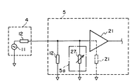
本実施形態における特徴は、受信回路5の入力部にインピーダンス可変回路5aを設け、このインピーダンス可変回路5aを制御手段8に設けた入力インピーダンス制御手段8aにより制御するようにしたことにある。図2に、インピーダンス可変回路5aの一実施形態の回路構成と、探触子4の簡便な等価回路を示す。
【0017】
探触子4の等価回路は、図示のように、信号源11と、信号源11に直列に接続された信号源抵抗12とで表すことができ、これらにより探触子4の等価出力インピーダンスZoが決まってくる。一方、受信回路5の入力部はプリアンプ21を有して構成され、探触子4の出力信号は口径選択切り換えスイッチ及び送受分離部を介してプリアンプ21の入力に供給される。プリアンプ21の入力端はインピーダンス22を介して接地され、かつスイッチ23とインピーダンス24の直列回路を介して接地されている。このスイッチ23とインピーダンス24の直列回路により、本発明のインピーダンス可変回路5aが形成されている。これらのインピーダンス22、インピーダンス可変回路5a及びプリアンプ21の入力インピーダンスにより、破線で示す受信回路5の等価入力インピーダンスZrが定まる。なお、図示においては、1つの振動素子の受信回路について示しているが、このような受信回路は、振動素子の数と口径選択方式に応じて複数備えられている。
【0018】
このように構成される本実施形態のインピーダンス可変回路5aの動作について説明する。スイッチ23をオン又はオフすることによって等価入力インピーダンスZiを2つの値に変えることができる。したがって、計測対象、計測部位、計測情報などの診断目的の違いに応じて、探触子4の種類を変更したり、送受信する超音波周波数を変更することにより、探触子4の等価出力インピーダンスZoが変化した場合は、これに応じてスイッチ23をオン又はオフしていずれかの等価入力インピーダンスZiを選択することにより、インピーダンス整合を図ることができる。例えば、ドプラ血流計測の場合は、通常の断層像を計測する場合よりも低い周波数帯域を利用するので、探触子4の等価出力インピーダンスは断層像計測の場合よりも高値を示す。そこで、インピーダンス整合を図る場合は、スイッチ23がオンのときに断層像計測に適した値に設定し、ドプラ血流計測に切り換える場合はスイッチ23をオフしてドプラ血流計測に適した値に切り換える。
【0019】
このように、受信回路5の等価入力インピーダンスを可変できるから、受信回路5の等価入力インピーダンスを診断目的に応じて変動する探触子4の等価出力インピーダンスに整合させることができる。その結果、信号伝送系における不要な信号反射を押さえて空間分解能を向上させることができる。
【0020】
他方、インピーダンス整合を図ることに代えて、診断目的に応じて最大感度が得られるように受信回路5の等価入力インピーダンスを可変することができる。これにより、信号ノイズ比(SN比)を向上させることができる。
【0021】
図3に、スイッチ23を自動的に切り換えるインピーダンス制御手段8aの一実施形態を示す。図示のように、インピーダンス制御手段8aは、判定部31とバッファ32を備えて構成される。判定部31は、制御手段8の他の機能から送られてくる探触子種類の識別信号、超音波周波数の識別信号及び診断モードの識別信号に基づいて、探触子4の等価出力インピーダンスZoを判定し、受信回路5の等価入力インピーダンスZiを求める。そして、求めたZiに調整するためのスイッチ23の切り替え信号をバッファ32を介してスイッチ23に出力する。これによって、スイッチ23はインピーダンス制御手段8aによって求められた等価入力インピーダンスZiに相当するオン、オフ状態に切り替えられる。なお、判定部31は、メモリで構成することができる。すなわち、探触子種類の識別信号、超音波周波数の識別信号及び診断モードの識別信号の組み合わせを読み出しアドレスとし、それらの組み合わせに対応させて等価入力インピーダンスを設定記憶させておけばよい。
【0022】
ここで、探触子種類は、例えば形状により、セクタ型、リニア型、コンベックス型などに分類することができ、超音波周波数は受信する超音波周波数に設定する。また、診断モードは、基本波撮像モード、高調波撮像モード、分解能重視モード、感度重視モード、又はそれらの組み合わせなどを設定することができる。
【0023】
また、本実施形態では、インピーダンス制御手段8aによりスイッチ8を自動的に切り替える例を説明したが、入力手段9を介して制御手段8を操作してスイッチ8を用手法により切り替えるようにすることもできる。
(第2実施形態)
図4に、図2に示した受信回路5の他の実施形態を示す。本実施形態の受信回路5のプリアンプ21は、フィードバックインピーダンス25によって等価入力インピーダンスZiが決定されることから、このフィードバックインピーダンス25にインピーダンス可変回路5bを並列に接続して、等価入力インピーダンスZiを可変するようにしたものである。インピーダンス可変回路5bは、図2の実施形態と同様に、スイッチ23とフィードバックインピーダンス26の直列回路で構成されている。スイッチ23は、図3のインピーダンス制御手段8aにより、又は入力手段9を介して切り替え操作するようにする。
【0024】
これにより、本実施形態のインピーダンス可変回路5bによれば、図2のインピーダンス可変回路5aと同様の効果を得ることができるだけでなく、図2の実施形態のようにアース間のインピーダンスを可変するよりも、プリアンプ21のフィードバックインピーダンスの値を可変する方がSN比が向上するので望ましい。
(その他の実施形態)
第1及び第2の実施形態では、スイッチ23を切り替えることにより、2つの等価入力インピーダンスZiに可変する受信回路5の例を示したが、本発明はこれに限らず、診断目的の応じて3つ以上の等価入力インピーダンスZiに可変する必要がある場合は、インピーダンス24又はフィードバックインピーダンス26を複数設け、これに合わせてスイッチ23を複数設けることにより対応できる。
【0025】
さらに、図5、図6に示すように、インピーダンス24又はフィードバックインピーダンス26に可変型のインピーダンス素子27,28を用いることにより、スイッチ23を用いなくても実現できる。可変型のインピーダンス素子27,28としては、図7に示すように、コンデンサ41に直列接続されたダイオード42に電流源43から流す電流量を調整することにより、あるいは、図8に示すように、FET44のゲート・ソース間に印加する電圧源45の電位を調節することにより実現できる。また、図9に示すように、プリアンプ10の入力端にトランス47を設け、このトランス47の巻数比を可変に形成し、昇圧及びインピーダンス変換させることにより実現できる。
【0026】
また、図3のインピーダンス制御手段に代えて、図10のように構成することができる。本実施形態は、図6、図7に示した可変型のインピーダンス素子27,28を介して等価入力インピーダンスを可変する場合に好適なものである。すなわち、図10に示すように、判定部31において求められた等価入力インピーダンスZiに相当するディジタル信号をアナログ信号に変換するディジタル・アナログ・コンバータ(ADC)33を設け、このADC33から出力される信号をアンプ34により図6の電流源43の電流指令、あるいは図7の電圧源45の電圧指令に変換して出力する。
【0027】
以上説明したように、本発明の各実施形態によれば、受信回路5の等価入力インピーダンスZiを可変できるから、基本波成分を用いて画像を再構成する一般的な診断像を計測する場合や、高調波成分を用いてコントラスト画像を計測する場合など、探触子4の等価出力インピーダンスが変化しても、これに合わせて受信回路5の等価入力インピーダンスZiを調整することにより、分解能重視のインピーダンス整合、あるいは感度重視のインピーダンスに調整でき、高い空間分解能あるいは高感度を確保することができる。
【0028】
【発明の効果】
以上述べたように、本発明によれば、診断目的に応じて、受信回路の入力インピーダンスないし等価入力インピーダンスを調整でき、診断条件が変わっても高い空間分解能あるいは高感度を確保することができる。
【図面の簡単な説明】
【図1】本発明を適用してなる超音波診断装置の一実施形態の全体構成のブロック図である。
【図2】本発明の特徴に係るインピーダンス可変回路の一実施形態の回路構成図である。
【図3】本発明の特徴に係るインピーダンス制御手段の一実施形態の構成図である。
【図4】本発明の特徴に係るインピーダンス可変回路の他の実施形態の回路構成図である。
【図5】図2のスイッチに代えて可変型インピーダンス素子を用いて構成した実施形態の回路構成図である。
【図6】図4のスイッチに代えて可変型インピーダンス素子を用いて構成した実施形態の回路構成図である。
【図7】本発明に係る可変型インピーダンス素子の一実施形態を示す図である。
【図8】本発明に係る可変型インピーダンス素子の他の一実施形態を示す図である。
【図9】本発明に係る可変型インピーダンス素子のさらに他の一実施形態を示す図である。
【図10】本発明の特徴に係るインピーダンス制御手段の他の実施形態の構成図である。
【符号の説明】
1 超音波パルス発生回路
2 送信回路
4 探触子
5 受信回路
5a インピーダンス可変回路
8 制御手段
8a インピーダンス制御手段
9 入力手段[0001]
TECHNICAL FIELD OF THE INVENTION
The present invention relates to an ultrasonic diagnostic apparatus, and more particularly, to a receiving circuit that receives and processes a reflected echo signal output from a probe.
[0002]
[Prior art]
An ultrasonic diagnostic apparatus applies an ultrasonic probe to the surface of a subject, transmits ultrasonic waves from the probe to the subject, and receives a reflected echo signal emitted from the inside of the subject by the probe. A diagnostic image such as a tomographic image of the state of the inside of the subject is obtained based on the received reflected echo signal. A probe for transmitting / receiving ultrasonic waves to / from the subject, and a probe supplied to the probe. A transmission circuit that outputs an ultrasonic drive signal to be transmitted, a reception circuit that receives and processes a reflected echo signal output from the probe, and reconstructs a diagnostic image based on the reflected echo signal output from the reception circuit. It comprises an image processing means, a monitor for displaying a diagnostic image reconstructed by the image processing means, and a control means for controlling these components.
[0003]
In such an ultrasonic diagnostic apparatus, the frequency and the like of the transmitted and received ultrasonic waves are changed in accordance with the difference in the diagnosis purpose such as the measurement target, the measurement site, and the measurement information. For example, when measuring a general diagnostic image, an ultrasound of a fundamental wave is transmitted from a probe, and an image is reconstructed using a fundamental wave component of a reflected echo signal. When a contrast agent is measured by injecting a contrast agent into a subject, an ultrasonic wave mainly including a fundamental wave component is transmitted from the probe, while a harmonic component derived from the contrast agent included in the reflected echo signal is transmitted. Is extracted and imaged (Patent Document 1). In addition, since the harmonic has a short wavelength and the acoustic ultrasonic beam has a small diffusion, the spatial resolution of the diagnostic image is improved by transmitting and receiving the harmonic ultrasonic waves from the probe. ing. Furthermore, since the low-frequency ultrasonic wave has a small signal attenuation rate in the living body, in consideration of the fact that the ultrasonic wave reaches a deep part, the ultrasonic wave having a frequency slightly lower than the maximum sensitivity frequency of the probe is transmitted and received. Improvements have been made in the sensitivity of acoustic Doppler measurements.
[0004]
[Patent Document 1]
JP-A-8-182680
[Problems to be solved by the invention]
As described above, when changing the frequency and the like of the ultrasonic wave to be transmitted and received according to the difference of the diagnostic purpose, the transmission circuit that supplies the ultrasonic drive signal to the probe, or the reflected echo signal output from the probe, By providing a filter or the like for passing a desired frequency component in a receiving circuit for receiving and amplifying, a gain of a desired frequency component such as a harmonic component is increased.
[0006]
However, when the output impedance of the probe with respect to the electric signal changes according to the frequency of the transmitted / received ultrasonic wave, the matching with the input impedance of the receiving circuit cannot be performed, and the problem that the spatial resolution may be deteriorated is not considered. There is a problem.
[0007]
That is, there are various types of ultrasonic probes, such as a sector type, a linear type, and a convex type, which differ depending on the shape and arrangement of the vibrating element, and the signal propagation from the probe to the receiving circuit depends on these types. The signal source resistance of the system is different, and the output impedance of the probe is different depending on the transmitted / received ultrasonic frequency. This is basically determined by the structure of the probe. The vibrating element is formed by sandwiching a piezoelectric element between the signal electrode and the ground electrode, and the signal source is determined by the piezoelectric element, distance between electrodes, electrode area, etc. This is because the resistance value is determined and the stray capacitance value in parallel is determined.
[0008]
On the other hand, conventionally, the input impedance of the receiving circuit of the ultrasonic diagnostic apparatus is fixedly set based on a typical type and frequency of a probe used in the ultrasonic diagnostic apparatus. Therefore, depending on the frequency of the ultrasonic wave to be used, the impedance of the probe and the receiving circuit may not have sufficient impedance matching, and the spatial resolution and contrast of the diagnostic image may not be sufficiently obtained.
[0009]
On the other hand, the input impedance of the receiving circuit when transmitting and receiving ultrasonic waves at a frequency lower than the maximum sensitivity frequency of the probe and improving the sensitivity is the same as the input impedance of the receiving circuit where impedance matching between the probe and the receiving circuit can be achieved. There is a problem that they do not always match.
[0010]
Therefore, conventionally, the input impedance of the receiving circuit is adjusted between the impedance at which matching can be achieved and the impedance at which the maximum sensitivity can be obtained, so that the spatial resolution and contrast of the diagnostic image are sacrificed, or the receiving sensitivity is sacrificed. There was an inconvenience.
[0011]
Therefore, an object of the present invention is to provide an ultrasonic diagnostic apparatus capable of adjusting an input impedance or an equivalent input impedance of a receiving circuit according to a diagnosis purpose.
[0012]
[Means for Solving the Problems]
The present invention solves the above problems by means described below.
[0013]
An impedance variable circuit for varying an equivalent input impedance is provided at an input section of the reflected echo signal receiving circuit.
[0014]
In this case, impedance control means for controlling the variable impedance circuit to control the equivalent input impedance can be provided. The input impedance control means obtains an equivalent input impedance based on at least one of the probe type, the ultrasonic frequency, and the diagnostic mode, and controls the variable impedance circuit based on the obtained equivalent input impedance. Alternatively, the variable impedance circuit can be controlled based on a command input from input means connected to the control means. In this case, the impedance control means can be provided with a memory table in which the equivalent input impedance is determined in correspondence with the probe type, the ultrasonic frequency and the diagnostic mode.
[0015]
BEST MODE FOR CARRYING OUT THE INVENTION
Hereinafter, embodiments of the present invention will be described with reference to the drawings.
(1st Embodiment)
FIG. 1 is a block diagram showing an overall configuration of an embodiment of an ultrasonic diagnostic apparatus to which the present invention is applied. As shown in FIG. 1, in the ultrasonic diagnostic apparatus according to the present embodiment, an ultrasonic pulse output from an ultrasonic pulse generation circuit 1 is input to a transmission circuit 2, where transmission processing such as transmission focus processing and amplification processing is performed. Is supplied to the ultrasonic probe 4 via the transmission / separation unit 3. Thereby, the plurality of vibrating elements constituting the probe 4 are driven, and ultrasonic waves are transmitted into the subject. The ultrasonic wave transmitted into the subject is reflected by the tissue or the like in the subject, and the reflected echo wave is received by the probe 4 and converted into an electric signal. The reflected echo signal converted by the probe 4 is input to the reception circuit 5 via the transmission / reception separation unit 3, where it undergoes reception processing such as amplification processing, phasing processing, and AD conversion. The reflected echo signal output from the receiving circuit 5 is input to the image processing means 3, where desired information is extracted from the reflected echo signal to reconstruct a diagnostic image. The diagnostic image reconstructed by the image processing means 6 is displayed on a monitor 7 such as a CRT or a TFT liquid crystal display. The ultrasonic pulse generation circuit 1, the transmission circuit 2, the reception circuit 5, the image processing means 6, and the like are controlled based on instructions from a control means 8 constituted by a computer or the like. The control unit 8 can execute various settings and controls based on a command input from the input unit 39. The control means 8 can scan an ultrasonic beam by controlling a diameter selection switch (not shown). Further, the phasing processing and AD conversion of the receiving circuit 5 and a part of the image processing means 36 can be configured by a computer or the like.
[0016]
The feature of this embodiment is that an impedance variable circuit 5a is provided at the input section of the receiving circuit 5, and the impedance variable circuit 5a is controlled by the input impedance control means 8a provided in the control means 8. FIG. 2 shows a circuit configuration of one embodiment of the impedance variable circuit 5a and a simple equivalent circuit of the probe 4.
[0017]
As shown in the drawing, the equivalent circuit of the probe 4 can be represented by a signal source 11 and a signal source resistor 12 connected in series to the signal source 11. Is decided. On the other hand, the input section of the receiving circuit 5 has a preamplifier 21, and the output signal of the probe 4 is supplied to the input of the preamplifier 21 via the aperture selection changeover switch and the transmission / reception separating section. The input terminal of the preamplifier 21 is grounded via an impedance 22, and grounded via a series circuit of a switch 23 and an impedance 24. The series circuit of the switch 23 and the impedance 24 forms the impedance variable circuit 5a of the present invention. The equivalent input impedance Zr of the receiving circuit 5 indicated by the broken line is determined by the impedance 22, the impedance variable circuit 5a, and the input impedance of the preamplifier 21. Although the drawing shows a receiving circuit of one vibrating element, a plurality of such receiving circuits are provided according to the number of vibrating elements and the aperture selection method.
[0018]
The operation of the thus configured impedance variable circuit 5a of the present embodiment will be described. By turning on or off the switch 23, the equivalent input impedance Zi can be changed to two values. Therefore, the equivalent output impedance of the probe 4 is changed by changing the type of the probe 4 or changing the ultrasonic frequency to be transmitted / received according to the difference in the diagnosis purpose such as the measurement target, the measurement site, and the measurement information. When Zo changes, the switch 23 is turned on or off in response to this to select one of the equivalent input impedances Zi, thereby achieving impedance matching. For example, in the case of Doppler blood flow measurement, since a lower frequency band is used than in the case of measuring a normal tomographic image, the equivalent output impedance of the probe 4 shows a higher value than in the case of tomographic image measurement. Therefore, when impedance matching is to be performed, a value suitable for tomographic image measurement is set when the switch 23 is on, and when switching to Doppler blood flow measurement, the switch 23 is turned off to obtain a value suitable for Doppler blood flow measurement. Switch.
[0019]
As described above, since the equivalent input impedance of the receiving circuit 5 can be changed, the equivalent input impedance of the receiving circuit 5 can be matched with the equivalent output impedance of the probe 4 which varies depending on the purpose of diagnosis. As a result, unnecessary signal reflection in the signal transmission system can be suppressed, and the spatial resolution can be improved.
[0020]
On the other hand, instead of achieving impedance matching, the equivalent input impedance of the receiving circuit 5 can be varied so as to obtain maximum sensitivity according to the purpose of diagnosis. Thereby, the signal noise ratio (SN ratio) can be improved.
[0021]
FIG. 3 shows an embodiment of the impedance control means 8a for automatically switching the switch 23. As shown in the figure, the impedance control unit 8a includes a determination unit 31 and a buffer 32. The determination unit 31 determines the equivalent output impedance Zo of the probe 4 based on the probe type identification signal, the ultrasonic frequency identification signal, and the diagnostic mode identification signal sent from other functions of the control unit 8. And an equivalent input impedance Zi of the receiving circuit 5 is obtained. Then, a switching signal of the switch 23 for adjusting to the obtained Zi is output to the switch 23 via the buffer 32. As a result, the switch 23 is switched on and off corresponding to the equivalent input impedance Zi obtained by the impedance control means 8a. Note that the determination unit 31 can be configured by a memory. That is, a combination of the identification signal of the probe type, the identification signal of the ultrasonic frequency, and the identification signal of the diagnosis mode may be set as the read address, and the equivalent input impedance may be set and stored in correspondence with the combination.
[0022]
Here, the probe type can be classified into, for example, a sector type, a linear type, a convex type, and the like according to the shape, and the ultrasonic frequency is set to the ultrasonic frequency to be received. In the diagnostic mode, a fundamental wave imaging mode, a harmonic imaging mode, a resolution emphasis mode, a sensitivity emphasis mode, or a combination thereof can be set.
[0023]
Further, in the present embodiment, an example has been described in which the switch 8 is automatically switched by the impedance control unit 8a. However, the switch 8 may be switched by the operation method by operating the control unit 8 via the input unit 9. it can.
(2nd Embodiment)
FIG. 4 shows another embodiment of the receiving circuit 5 shown in FIG. In the preamplifier 21 of the receiving circuit 5 of the present embodiment, since the equivalent input impedance Zi is determined by the feedback impedance 25, the impedance variable circuit 5b is connected in parallel to the feedback impedance 25 to vary the equivalent input impedance Zi. It is like that. The impedance variable circuit 5b is configured by a series circuit of a switch 23 and a feedback impedance 26, as in the embodiment of FIG. The switch 23 is switched by the impedance control means 8a of FIG.
[0024]
Thus, according to the impedance variable circuit 5b of the present embodiment, not only the same effect as the impedance variable circuit 5a of FIG. 2 can be obtained, but also the impedance between the grounds is changed as in the embodiment of FIG. Also, it is desirable to change the value of the feedback impedance of the preamplifier 21 because the SN ratio is improved.
(Other embodiments)
In the first and second embodiments, the example of the receiving circuit 5 that can be changed to two equivalent input impedances Zi by switching the switch 23 has been described. However, the present invention is not limited to this. When it is necessary to change the input impedance to one or more equivalent input impedances Zi, a plurality of impedances 24 or feedback impedances 26 may be provided, and a plurality of switches 23 may be provided accordingly.
[0025]
Further, as shown in FIG. 5 and FIG. 6, by using variable impedance elements 27 and 28 for the impedance 24 or the feedback impedance 26, the present invention can be realized without using the switch 23. As the variable impedance elements 27 and 28, as shown in FIG. 7, by adjusting the amount of current flowing from a current source 43 to a diode 42 connected in series to a capacitor 41, or as shown in FIG. This can be realized by adjusting the potential of the voltage source 45 applied between the gate and the source of the FET 44. Also, as shown in FIG. 9, a transformer 47 is provided at the input end of the preamplifier 10, the turns ratio of the transformer 47 is variably formed, and the transformer 47 can be realized by boosting and impedance conversion.
[0026]
Further, instead of the impedance control means of FIG. 3, a configuration as shown in FIG. 10 can be used. This embodiment is suitable for a case where the equivalent input impedance is varied via the variable impedance elements 27 and 28 shown in FIGS. That is, as shown in FIG. 10, a digital-to-analog converter (ADC) 33 for converting a digital signal corresponding to the equivalent input impedance Zi obtained by the determination unit 31 into an analog signal is provided, and a signal output from the ADC 33 is provided. Is converted into a current command from the current source 43 in FIG. 6 or a voltage command from the voltage source 45 in FIG.
[0027]
As described above, according to each embodiment of the present invention, since the equivalent input impedance Zi of the receiving circuit 5 can be changed, it is possible to measure a general diagnostic image in which an image is reconstructed using the fundamental wave component, Even when the equivalent output impedance of the probe 4 changes, for example, when a contrast image is measured using a harmonic component, by adjusting the equivalent input impedance Zi of the receiving circuit 5 in accordance with the change, the emphasis on resolution is increased. It can be adjusted to impedance matching or impedance with an emphasis on sensitivity, and high spatial resolution or high sensitivity can be secured.
[0028]
【The invention's effect】
As described above, according to the present invention, the input impedance or equivalent input impedance of the receiving circuit can be adjusted according to the purpose of diagnosis, and high spatial resolution or high sensitivity can be ensured even when the diagnostic conditions change.
[Brief description of the drawings]
FIG. 1 is a block diagram of an overall configuration of an embodiment of an ultrasonic diagnostic apparatus to which the present invention is applied.
FIG. 2 is a circuit configuration diagram of an embodiment of an impedance variable circuit according to a feature of the present invention.
FIG. 3 is a configuration diagram of an embodiment of an impedance control unit according to a feature of the present invention.
FIG. 4 is a circuit configuration diagram of another embodiment of the variable impedance circuit according to the features of the present invention.
FIG. 5 is a circuit configuration diagram of an embodiment configured using a variable impedance element instead of the switch of FIG. 2;
6 is a circuit configuration diagram of an embodiment configured using a variable impedance element instead of the switch of FIG. 4;
FIG. 7 is a diagram showing one embodiment of a variable impedance element according to the present invention.
FIG. 8 is a diagram showing another embodiment of the variable impedance element according to the present invention.
FIG. 9 is a view showing still another embodiment of the variable impedance element according to the present invention.
FIG. 10 is a configuration diagram of another embodiment of the impedance control means according to the feature of the present invention.
[Explanation of symbols]
DESCRIPTION OF SYMBOLS 1 Ultrasonic pulse generation circuit 2 Transmission circuit 4 Probe 5 Receiving circuit 5a Impedance variable circuit 8 Control means 8a Impedance control means 9 Input means