JP2004357165A - Offset beat canceler - Google Patents
Offset beat canceler Download PDFInfo
- Publication number
- JP2004357165A JP2004357165A JP2003154943A JP2003154943A JP2004357165A JP 2004357165 A JP2004357165 A JP 2004357165A JP 2003154943 A JP2003154943 A JP 2003154943A JP 2003154943 A JP2003154943 A JP 2003154943A JP 2004357165 A JP2004357165 A JP 2004357165A
- Authority
- JP
- Japan
- Prior art keywords
- signal
- video
- frequency
- output
- oscillator
- Prior art date
- Legal status (The legal status is an assumption and is not a legal conclusion. Google has not performed a legal analysis and makes no representation as to the accuracy of the status listed.)
- Pending
Links
Images


Landscapes
- Noise Elimination (AREA)
- Picture Signal Circuits (AREA)
- Details Of Television Systems (AREA)
Abstract
Description
【0001】
【発明の属する技術分野】
本発明は,受信アンテナにて受信したテレビ放送信号の中から,希望波に対して送信周波数が所定周波数オフセットされた妨害波信号成分を除去するオフセットビートキャンセラに関する。
【0002】
【従来の技術】
従来より,近接する地域で同一の放送チャンネルを利用したテレビ放送を行う際には,各テレビ放送信号の送信周波数に±10.01kHzのオフセットを設けて,テレビ受像器で映像信号を再生した際に画面に現れる縞模様(ビート)を目立たなくするようにしている。しかし,妨害波の量が多ければビートも顕著に現れることになるし,聴視者からはよりよい画質の要求がある。
【0003】
そこで,近年では,こうしたビート障害を防止するために,ビート障害が発生する放送チャンネルのテレビ放送信号を所定周波数帯に周波数変換した映像中間周波信号(以下,映像IF信号ともいう)から,希望波の映像搬送波を抽出し,この映像搬送波を用いて映像IF信号を直交検波することにより,妨害波信号成分を含むQ信号を生成し,更に,アナログフィルタを用いて,その生成したQ信号から妨害波信号成分を抽出して,この妨害波信号成分を映像IF信号から除去するオフセットビートキャンセラが提案されている(例えば,特許文献1,特許文献2参照)。
【0004】
【特許文献1】
特開平8−98061号公報
【特許文献2】
特開平9−55671号公報
【0005】
【発明が解決しようとする課題】
ところで,上記提案のオフセットビートキャンセラは,何れも,映像IF信号を信号処理することによって,妨害波信号成分を除去した映像IF信号を生成するものであるため,ホーム共同受信等で複数の受信端末(テレビチューナ等)に伝送される受信信号の中から妨害波信号成分を除去するようにするには,受信信号の中から妨害波を除去すべき放送チャンネルのテレビ放送信号を選局する選局部や,該選局部から出力される映像IF信号を直交検波することにより,該中間IF信号に含まれる妨害波信号成分を抽出し,該抽出した妨害波信号成分を除去した映像信号もしくは映像IF信号を生成する映像信号処理手段や,妨害波信号成分を除去した前記映像IF信号を用いてテレビ放送信号を生成する変調部を別途設ける必要がある。
【0006】
そして,このように構成されたオフセットビートキャンセラにおいて,選局部にてテレビ放送信号を選局する際(換言すれば受信信号を周波数変換する際)に用いる局部発振器の出力に位相ノイズが存在すると,選局部で得られる映像IF信号にその位相ノイズ成分が重畳されてしまい,映像IF信号の信号劣化を招くことになる。
更に,前記映像IF信号を映像信号処理部において直交検波する際に用いる,キャリア再生部を構成する振幅制限器は,前記映像IF信号を基準信号として用いるため,前記振幅制限器の出力における変調波の抑圧比(以下,映像信号抑圧比という)が悪いと,搬送波に雑音(ここでは振幅変調成分,以下AM成分と言う)が含まれることになり直交検波において検波された信号の劣化を招くことになる。
更に加えて,当該振幅制限器を通して振幅制限した信号(換言すると,希望波信号の搬送波信号)を基準信号として基準発振器の出力が制御されるように構成されていれば,前記基準発振器の出力に位相ノイズが存在することで,直交検波で得られる検波信号にその位相ノイズ成分が重畳されてしまい,妨害波信号成分を除去する信号処理手段からの出力信号の劣化を招くことになる。
【0007】
一方,こうした問題を防止するには,選局部で用いる局部発振器を純度の高い局部発振信号を発生できるように,局部発振器や局部発振器の発振周波数を制御する制御回路の精度を上げると共に,キャリア再生部の振幅制限器の映像信号抑圧比を改善することが必要となる。また,キャリア再生部の基準発振器においても,前記選局部の局部発振器と同様に,前記基準発振器を純度の高い発振信号を発生できるように,基準発振器や基準発振器の発振周波数を制御する制御回路の精度を上げることが必要となる。しかしながらそのためには,発振器や制御回路等に高価なものを使用しなければならず,オフセットビートキャンセラのコストアップを招くという問題が生じる。また,作り難い,大きくなってしまうといった問題もあった。
【0008】
本発明は,こうした問題に鑑みなされたものであり,テレビ放送信号選局用の選局部と,該選局部から出力される映像IF信号を直交検波することにより,該中間IF信号に含まれる妨害波信号成分を抽出し,該抽出した妨害波信号成分を除去した映像信号もしくは映像IF信号を生成する映像信号処理手段や,妨害波信号成分を除去した前記映像IF信号を用いてテレビ放送信号を生成する変調部を備えたオフセットビートキャンセラにおいて,選局部や映像信号処理手段を構成するキャリア再生部の基準発振器や振幅制限器等の特性の最適な条件を提供することで,それらの特性(例えば位相ノイズや,映像信号等の変調信号の漏れによる残留ノイズ)による影響を受けることなく,テレビ放送画像を綺麗に再生できるようにすると共に,コストダウン,作りやすいオフセットビートキャンセラを提供することを目的とする。
【0009】
【課題を解決するための手段】
かかる目的を達成するためになされた請求項1記載の発明は, 受信アンテナから入力される受信信号の中から,希望波に対して送信周波数が所定周波数オフセットされた妨害波を含む所定放送チャンネルのテレビ放送信号を選局して,該テレビ放送信号の映像中間周波信号及び音声中間周波信号を出力する選局手段と,該選局手段から出力される映像中間周波信号を直交検波することにより,該映像中間周波信号に含まれる妨害波信号成分を抽出し,該抽出した妨害波信号成分を除去した映像信号若しくは映像中間周波信号を生成する映像信号処理手段と,該映像信号処理手段にて生成された映像信号と,前記選局復調手段から出力される音声中間周波信号とに基づき,所定放送チャンネルのテレビ放送信号を生成するテレビ放送信号生成手段と,を備え,該生成されたテレビ放送信号を受信信号として出力するオフセットビートキャンセラであって,前記選局手段が前記受信信号から所定放送チャンネルのテレビ放送信号の少なくとも映像信号を前記映像中間周波信号に周波数変換するのに使用する局部発振器の出力特性の一つである位相雑音が,オフセット周波数1kHzにおいて95dBc/Hz〜130dBc/Hzであり,前記映像信号処理手段が前記映像中間周波信号を直交検波するのに使用するキャリア再生部において,当該キャリア再生部を構成する振幅制限器の特性の一つである映像信号抑圧比が15dB〜40dBであり,前記映像信号処理手段が前記映像中間周波信号を直交検波するのに使用するキャリア再生部を構成する基準発振器の出力特性の一つである位相雑音が,オフセット周波数1kHzにおいて70dBc/Hz〜90dBc/Hzであるように構成したことを特徴とする。
【0010】
つまり,選局手段やキャリア再生部において使用されている発振器(詳しくは選局手段においては,該選局手段が受信信号から所定放送チャンネルのテレビ放送信号の映像信号を映像中間周波信号に周波数変換するのに使用する局部発振器であり,キャリア再生部においては,前記選局手段から出力された映像中間周波信号を直交検波するための基準発振器である)から出力される位相ノイズがある程度低ければ,再生画像に影響を与えることはない。
【0011】
そこで,本発明では,少なくとも選局手段の局部発振器とキャリア再生部に使用されている振幅制限器と基準発振器において,これらの構成要素の内,雑音成分を発生させる構成要素の特性に着目して,これらを夫々最適化して組合せることにより,これらの構成要素の特性によってテレビ放送の再生画像が劣化するのを防止するようにしているのである。
【0012】
そして,このように各構成要素の特性を夫々最適な値に組合せることにより,選局手段やキャリア再生部に設けられる基準発振器やこの基準発振器の発振周波数を制御する制御回路の精度を高めて,基準発振器から出力される位相ノイズを全周波数領域で抑制する必要がないので,選局手段やキャリア再生部,延いては,オフセットビートキャンセラを,比較的安価に実現できることになる。
なお,組合せとしては本発明(請求項1)のように選択手段における局部発振器の出力特性は,その位相ノイズの特性が,オフセット周波数1kHzにおいて95dBc/Hz〜130dBc/Hzであって,キャリア再生部を構成する振幅制限器の特性は,その映像信号抑圧比が15dB〜40dBであり,前記映像信号処理手段が前記映像中間周波信号を直交検波するのに使用するキャリア再生部を構成する基準発振器の出力特性の一つである位相雑音が,オフセット周波数1kHzにおいて70dBc/Hz〜90dBc/Hzであるように構成することが望ましい。
【0013】
また,本発明(請求項2)のように夫々の発振器は,発振周波数を制御可能な周波数可変発振器と,ローパスフィルタと発振周波数を制御するPLL回路と基準発振器(キャリア再生部の基準信号は,選局手段から出力される映像中間周波信号)とを備えたPLL制御でもって構成しても良い。
【0014】
【発明の実施の形態】
以下に本発明の実施形態を図面と共に説明する。
図1は本発明が適用された第1実施例のテレビ放送受信システム全体の構成を表わす概略構成図である。なお,本実施例のテレビ放送受信システムは日本国内用のものであり,以下に説明するVHF帯及びUHF帯のテレビ放送は,帯域幅が6MHzのNTSC方式で行われるものとする。
【0015】
図1に示す如く,本実施例のテレビ放送受信システムは,屋外に設置したアンテナからの受信信号を伝送線を介して建造物内の各部屋に伝送する共同受信システムであり,テレビ放送受信用の受信アンテナとして,地上局から送信されたVHF帯及びUHF帯の放送電波をそれぞれ受信するVHFアンテナ2及びUHFアンテナ4と,放送衛星(BS)や通信衛星(CS)からの送信電波を受信するBS/CSアンテナ6とを備える。
【0016】
なお,BS/CSアンテナ6は,反射鏡6aと,支持腕を介して反射鏡6aの焦点位置に配置された受信部6bとからなり,受信部6bに内蔵されたコンバータによって,受信信号をBS/CS−IF信号に周波数変換(ダウンコンバート)して出力する。
【0017】
そして,これら各受信アンテナ2〜6からの受信信号(VHF受信信号,UHF受信信号,BS/CS−IF信号)は,それぞれ,同軸ケーブルからなる伝送線を介して,ブースタ(増幅器)8まで伝送され,このブースタ8にて所定レベルまで増幅される。また,ブースタ8にて増幅された各受信信号(VHF受信信号,UHF受信信号,BS/CS−IF信号)は,ブースタ8内で混合されて,後段のオフセットビートキャンセラ20に入力され,このオフセットビートキャンセラ20から端末側の伝送線上に出力される。
【0018】
また,端末側の伝送線には,分配器10が接続されており,オフセットビートキャンセラ20から出力された受信信号は,分配器10にて複数系統(図では4系統)に分配され,更に,その分配された各系統の伝送線上に直列に接続された複数の直列ユニット12を介して,各直列ユニット12が設置された各部屋の受信端末(例えば,図示しない受信画像を表示するTV受像機)まで伝送される。
【0019】
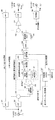
次に,このオフセットビートキャンセラ20の構成を図2を用いて詳しく説明する。
図2に示すように,オフセットビートキャンセラ20は,ブースタ8から出力された受信信号を伝送線(同軸ケーブル)を介して入力するための入力端子Tinと,受信信号を出力するための出力端子Toutとを備える。
【0020】
そして,入力端子Tinに入力された受信信号の内,BS/CS−IF信号は,この信号のみを選択的に通過させるハイパスフィルタ(以下,ハイパスフィルタをHPFと記載する)24を介して内部に取り込まれ,ビートキャンセラ20内に形成されたBS/CS−IF信号用の通過経路,及び,出力端子Tout側に設けられたHPF26を介して,出力端子Toutまで伝送されて,出力端子Toutから端末側に出力される。
【0021】
また,入力端子Tinに入力された受信信号の内,VHF受信信号及びUHF受信信号は,VHF及びUHF帯の受信信号のみを選択的に通過させるローパスフィルタ(以下,ローパスフィルタをLPFと記載する)22を介して内部に取り込まれ,分配回路28にて2分配される。そして,この分配回路28にて分配された一方の受信信号(VHF・UHF信号)は,ビートキャンセラ20内に形成されたVHF・UHF信号用の通過経路を介して,出力端子Tout側の混合回路42まで伝送される。
【0022】
一方,分配回路28にて分配された他方の受信信号は,UHF選局部30に入力される。このUHF選局部30は,制御部50から選局チャンネル制御信号によって指定されたUHF帯で所定放送チャンネルのテレビ放送信号を選局して,映像搬送波が所定周波数(例えば,58.75MHz)となる映像中間周波信号(映像IF信号)と,音声多重信号を含む複合音声信号を出力する。なお,このUHF選局部30は,本発明の選局手段に相当する。
【0023】
そして,UHF選局部30から出力された映像IF信号は,分配回路29を介して一方は直交検波部32に入力され,他方はキャリア再生部31に入力される。このキャリア再生部31と直交検波部32にて,映像IF信号に含まれる映像搬送波を用いて直交検波される。また,この直交検波部32で直交検波されたI信号とQ信号とは,それぞれ,ビートキャンセル用のデジタル処理部34に入力され,デジタル処理部34にて,妨害波信号成分を除去したベースバンドの映像信号に変換される。
【0024】
そして,この映像信号と,UHF選局部30から出力された音声信号(複合音声信号)とは,それぞれ,UHF変調部36に入力され,このUHF変調部36にて,制御部50から出力チャンネル制御信号によって指定された所定放送チャンネル(出力チャンネル)のUHF帯のテレビ放送信号に変換される。なお,このUHF変調部36は,本発明のテレビ放送信号生成手段に相当する。
【0025】
次に,このUHF変調部36にて生成されたテレビ放送信号は,UHF帯のテレビ放送信号のみを選択的に通過させるバンドパスフィルタ(以下,バンドパスフィルタをBPFと記載する)38を介して,ゲインコントロール(GC)用のボリュームVRを備えた増幅部40に入力され,この増幅部40にて所定レベルまで増幅された後,混合回路42に入力される。
【0026】
この結果,混合回路42では,VHF・UHF信号用の通過経路を通過したVHF・UHF信号とUHF変調部36で生成された所定出力チャンネルのテレビ放送信号とが混合されることになる。
そして,この混合回路42にて混合されたVHF・UHF信号は,増幅回路44にて所定レベルまで更に増幅された後,VHF及びUHF帯の受信信号のみを選択的に通過させるLPF46を介して,出力端子Toutまで伝送され,出力端子Toutから,BS/CS−IF信号と一緒に端末側に出力される。
【0027】
ここで,デジタル処理部34と直交検波部32とキャリア再生部31は,本発明の映像信号処理手段33に相当するものであり,本実施例では,デジタル処理部34において,Q信号をデジタル処理することにより,I信号に含まれる妨害波信号成分を生成し,I信号からこの妨害波信号成分を除去する。
つまり,映像IF信号に含まれる希望波映像信号をA(t),その搬送波(映像搬送波)をcos(ωt)とし,妨害波映像信号をB(t),その搬送波(映像搬送波)をcos{(ω+δ)t+Φ}とした場合,映像IF信号は,
映像IF信号=A(t)cos(ωt)
+B(t)cos{(ω+δ)t+Φ}
と記述でき,直交検波後のI信号及びQ信号は,それぞれ,
I信号=A(t)+B(t)cos(δt+Φ)
Q信号=B(t)sin(δt+Φ)
となることから,デジタル処理部34では,Q信号をデジタル処理することにより,I信号に含まれる妨害波信号成分である「B(t)cos(δt+Φ)」を生成し,この妨害波信号成分をI信号から除去するのである。
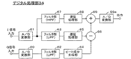
【0028】
具体的には,再生したテレビ画像からビートを除去するには,映像信号の低域成分(周波数:0〜数十kHz)に関して妨害波信号成分を除去できれば充分であることから,デジタル処理部34では,図3に示すように,まず,Q信号をA/D変換部60を介してデジタルデータとして取り込み,その取り込んだQ信号を,LPFとして機能するフィルタ部62にてフィルタ処理することにより,Q信号の低域成分のみを抽出し,ビート成分生成部64にて,その抽出したQ信号の低域成分から,上記妨害波信号成分「B(t)cos(δt+Φ)」を生成する。
【0029】
また,デジタル処理部34では,I信号をA/D変換部61を介してデジタルデータとして取り込み,その取り込んだI信号を,LPFとして機能するフィルタ部63と,HPFとして機能するフィルタ部67とを用いて,I信号の低域成分と高域成分とに分離する。
【0030】
そして,ビート成分生成部64から出力される妨害波信号成分は,ビート成分生成部64の処理動作によって,各フィルタ部63,67を通過したI信号の低域成分及び高域成分よりも遅れることから,フィルタ部63,67を通過したI信号の低域成分及び高域成分を,ビート成分生成部64で生成された妨害波信号成分と同期させるために,I信号の低域成分及び高域成分を,それぞれ,遅延処理部65,68で遅延処理する。
【0031】
そして,最後に,減算処理部66にて,遅延処理後のI信号の低域成分からビート成分生成部64で生成された妨害波信号成分を減算する減算処理を行い,更に,その減算処理後のI信号の低域成分と遅延処理後のI信号の高域成分とを加算処理部69にて加算処理することにより,妨害波信号成分を除去した映像信号(詳しくは映像データ)を生成し,これをD/A変換部69aにてアナログの映像信号に変換した後,UHF変調部36に出力する。
【0032】
従って,デジタル処理部34からは,オフセットビート障害の原因となる妨害波信号成分を除去した映像信号が出力されることになり,しかも,デジタル処理部34では,直交検波後のI信号及びQ信号を一旦デジタルデータに変換してデジタル処理することにより,妨害波信号成分を除去した映像信号を生成することから,周囲温度の影響を受けることなく,妨害波信号成分を除去した映像信号を安定して生成することができる。
【0033】
次に,オフセットビートキャンセラ20には,UHF変調部36が生成するテレビ放送信号の放送チャンネル(出力チャンネル)を外部操作によって設定できるようにするために,出力チャンネル設定部48が設けられている。
そして,制御部50は,マイクロコンピュータにて構成されており,この出力チャンネル設定部48から入力される出力チャンネルの設定指令に従い,UHF変調部36がテレビ放送信号を生成する際の放送チャンネル(出力チャンネル)を制御する。
【0034】
また,UHF選局部30の選局チャンネルは,予めEEPROM52に記憶されており,制御部50は,UHF選局部30の選局チャンネルを,このEEPROM52に記憶された選局チャンネルに固定する。
なお,オフセットビートキャンセラ20には,図示しないDCアダプタ等から例えば直流15Vの直流電源を供給するための電源入力端子Tdcが設けられており,上述した各内部回路には,この電源入力端子Tdcに供給された直流電源から上述した内部回路を動作させるための各種電源電圧を生成する電源部56を介して,動作用の電源電圧を供給するようにされている。
【0035】
ところで,本実施例のオフセットビートキャンセラ20においては,デジタル処理部34において,直交検波部32で得られたQ信号をデジタル処理することによって,映像信号に含まれる妨害波信号成分を生成し,これをI信号から除去するようにしているので,妨害波信号成分をアナログフィルタを用いて生成する従来のオフセットビートキャンセラに比べて,周囲温度の影響を受けることなく妨害波信号成分を除去することができるようになるのであるが,UHF選局部30で受信信号から映像IF信号を生成するのに用いられる局部発振器70(図4参照)から出力される位相ノイズの信号レベルが高いと,オフセットビートキャンセラ20でオフセットビート障害の原因となる妨害波信号成分を除去したにも関わらず,オフセットビートキャンセラ20から出力されるテレビ放送信号を受信端末で再生した際の再生画像にビートが発生してしまうことがある。
【0036】
そこで,本実施例では,こうした問題を防止するため,UHF選局部30に内蔵された局部発振器70の出力特性における位相ノイズを,オフセット周波数1kHzにおいて95dBc/Hz〜130dBc/Hzとなるように設定している。
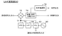
【0037】
即ち,UHF選局部30は,図4に示すように,電圧制御型の周波数可変発振器(VCO)からなる局部発振器70を備え,この局部発振器70から出力される局部発振信号Loと分配回路28を介して入力される受信信号(VHF・UHF信号)とを混合することにより,制御部50から指定された所定チャンネルのテレビ放送信号の映像搬送波が所定周波数(例えば,58.75MHz)となるように受信信号を周波数変換し,更に,映像・音声分離フィルタ74にて,その周波数変換後の受信信号の中から,所定チャンネルのテレビ放送信号の映像信号(詳しくは映像IF信号)と音声信号とをそれぞれ分離し,その分離した音声信号を音声復調部78において復調した音声出力と映像・音声分離フィルタ74にて分離した映像信号(映像IF信号)とを,それぞれ,出力するように構成されている。
【0038】
また,UHF選局部30には,制御部50から指定された所定チャンネルのテレビ放送信号を選局して,その映像IF信号及び音声信号(複合音声放送)を出力できるようにするために,発振周波数が固定された基準発振器80と,この基準発振器80からの出力と局部発振器70からの出力との周波数の比が制御部50からの選局チャンネル制御信号に対応した値となるように局部発振器70の発振周波数を制御するPLL回路82と,PLL回路82から局部発振器70への制御信号の出力経路に設けられたLPF(ローパスフィルタ)84とが備えられている。
【0039】
そして,本実施例では,このLPF84のフィルタ特性を調整することによって,局部発振器70の出力特性を上記のように設定し,局部発振器70から出力される位相ノイズによって再生画像が劣化するのを防止しているのである。
【0040】
更に,図5に示すように本発明の映像信号処理手段33を構成する直交検波部32において直交検波するために必要なキャリア再生部31にも基準発振器31eが備えられている。このキャリア再生部31は,上記選局部30から出力される映像IF信号を,フィルタ31aと振幅制限器32bを介して出力された信号を基準信号として,該基準信号と前記基準発振器31eからの出力との周波数の比が予め設定された値となるように前記基準発振器31eの発振周波数を制御するPLL回路31cと,該PLL回路31cから前記基準発振器31eへの制御信号の出力経路に設けられたローパスフィルタ31dとから構成されている。従って,上述のように選局部30において,周波数変換するための局部発振器70の位相ノイズを最適に設定したとしても,この映像IF信号を基準としたキャリア再生部31において変調信号成分の残留による雑音成分が加わると,再生画像が劣化することになってしまう。
【0041】
そこで,前記キャリア再生部31において,フィルタ31aは例えば狭帯域なクリスタルフィルタでもって構成され,前記映像IF信号を通過させるものであり,振幅制限器31bは映像IF信号に含まれるAM成分を抑圧することで基準信号としてPLL回路31cに入力されるのである。従ってこのAM成分を抑圧することが基準発振器31eの純度を良好に保つことになり,本発明においては前記振幅制限器31bに,例えば映像搬送波信号に正弦波信号で振幅変調をかけた信号を入力した場合,該振幅制限器31bの出力において映像搬送波信号より1kHz離れたところの映像信号抑圧比が,15dB〜40dBとなるように設定している。また選局部30の局部発振器70と同様な理由から,キャリア再生部31の基準発振器31eの位相ノイズを,オフセット周波数1kHzにおいて70dBc/Hz〜90dBc/Hzとなるように設定されている。
【0042】
従って,本実施例のオフセットビートキャンセラ20によれば,受信信号に含まれる妨害波信号成分によって所定放送チャンネルのテレビ放送信号を受信端末側で再生した際に生じるオフセットビート障害を防止できるだけでなく,オフセットビート障害を防止するためにUHF選局部30でテレビ放送信号を選局するのに用いられる局部発振器70からの位相ノイズだけでなく,キャリア再生部31の振幅制限器31bの映像信号抑圧比,同基準発振器31eの位相ノイズによって再生画像が劣化するのも防止でき,UHF選局部30で選局したテレビ放送信号を受信端末側で綺麗に再生できることになる。
尚,図2に示す電源部52から内部回路へ供給される電源は,出力電圧リプルが小さい方が良いし,外部ノイズや高周波電界による影響を出来うる限り小さくすることも各構成要素を動作させるときにノイズを発生させないので,再生画像が劣化するのを防止できる。
【0043】
以上,本発明の一実施例について説明したが,本発明は上記実施例に限定されるものではなく,種々の態様を採ることができる。
例えば,上記実施例では,デジタル処理部34において,I信号を低域成分と高域成分とに分離するものとして説明したが,I信号は必ずしも分離する必要はなく,単にA/D変換部61でA/D変換したI信号をそのまま遅延処理部で遅延させて,そのI信号から妨害波信号成分を除去するようにしてもよい。
【0044】
【発明の効果】
以上詳述したように,本願の発明によれば,選局手段やキャリア再生部において使用されている発振器(詳しくは選局手段においては,該選局手段が受信信号から所定放送チャンネルのテレビ放送信号の映像信号を映像中間周波信号に周波数変換するのに使用する局部発振器であり,キャリア再生部においては,前記選局手段から出力された映像中間周波信号を直交検波するための基準発振器である)から出力される位相ノイズがある程度低ければ,再生画像に影響を与えることはない。
【0045】
そこで,本発明では,少なくとも選局手段の局部発振器とキャリア再生部に使用されている振幅制限器と基準発振器において,これらの構成要素の内,雑音成分を発生させる構成要素の特性に着目して,これらを夫々最適化して組合せることにより,これらの構成要素の特性によってテレビ放送の再生画像が劣化するのを防止するようにしているのである。
【0046】
そして,このように各構成要素の特性を夫々最適な値に組合せることにより,選局手段やキャリア再生部に設けられる発振器やこの発振器の発振周波数を制御する制御回路の精度を高めて,発振器から出力される位相ノイズを全周波数領域で抑制する必要がないので,選局手段やキャリア再生部,延いては,オフセットビートキャンセラを,比較的安価に実現できることになるのである。
なお,組合せとしては本発明のように,選択手段における局部発振器の出力特性は,その位相ノイズの特性が,オフセット周波数1kHzにおいて95dBc/Hz〜130dBc/Hzであって,キャリア再生部を構成する振幅制限器の特性は,その映像信号抑圧比が15dB〜40dBであり,前記映像信号処理手段が前記映像中間周波信号を直交検波するのに使用するキャリア再生部を構成する基準発振器の出力特性の一つである位相雑音が,オフセット周波数1kHzにおいて70dBc/Hz〜90dBc/Hzであるように構成することが望ましい。更にこれらの発振器をPLL制御による回路で構成することで,より安定性の良いオフセットビートキャンセラを提供できる。
【図面の簡単な説明】
【図1】実施例のテレビ放送受信システム全体の構成を表す概略構成図である。
【図2】図1に示すオフセットビートキャンセラの構成を表すブロック図である。
【図3】図2に示すデジタル処理部の構成を表すブロック図である。
【図4】図2に示すUHF選局部の構成を表すブロック図である。
【図5】図2に示すキャリア再生部の構成を表すブロック図である。
【符号の説明】
2…VHFアンテナ,4…UHFアンテナ,6…BS/CSアンテナ,8…ブースタ,10…分配器,12…直列ユニット,20…オフセットビートキャンセラ,22,46,82…LPF,24,26…HPF,28,29…分配回路,30…UHF選局部,31…キャリア再生部,31a…フィルタ,31b…振幅制限器,31c…PLL回路,31d…ローパスフィルタ,31e…基準発振器,32…直交検波部,33…映像信号処理手段,34…デジタル処理部,36…UHF変調部,38…BPF,40…増幅部,42…混合回路,44…増幅回路,48…出力チャンネル設定部,50…制御部,52…EEPROM,56…電源部,60,61…A/D変換部,62,63,67…フィルタ部,64…ビート成分生成部,65,68…遅延処理部,66…減算処理部,69…加算処理部,69a…D/A変換部,70…局部発振器,72…ミキサ,74…映像・音声分離フィルタ,78…周波数変換部,80…基準発振器,82…PLL回路,Tdc…電源入力端子,Tin…入力端子,Tout…出力端子,VR…ボリューム。[0001]
TECHNICAL FIELD OF THE INVENTION
The present invention relates to an offset beat canceller that removes, from a television broadcast signal received by a receiving antenna, an interference wave signal component whose transmission frequency is offset by a predetermined frequency with respect to a desired wave.
[0002]
[Prior art]
2. Description of the Related Art Conventionally, when performing a television broadcast using the same broadcast channel in an adjacent area, an offset of ± 10.01 kHz is provided for a transmission frequency of each television broadcast signal, and a video signal is reproduced by a television receiver. To make the stripes (beats) appearing on the screen less noticeable. However, if the amount of the interfering wave is large, the beat will appear significantly, and there is a demand from the viewer for better image quality.
[0003]
Therefore, in recent years, in order to prevent such a beat failure, a desired frequency is converted from a video intermediate frequency signal (hereinafter, also referred to as a video IF signal) obtained by frequency-converting a television broadcast signal of a broadcast channel in which a beat failure occurs into a predetermined frequency band. A Q signal including a disturbing signal component is generated by extracting the video carrier of the above and performing quadrature detection of the video IF signal using the video carrier, and furthermore, an analog filter is used to generate a Q signal from the generated Q signal. An offset beat canceller that extracts a wave signal component and removes this interference wave signal component from a video IF signal has been proposed (for example, see
[0004]
[Patent Document 1]
JP-A-8-98061
[Patent Document 2]
JP-A-9-55671
[0005]
[Problems to be solved by the invention]
By the way, each of the proposed offset beat cancellers processes a video IF signal to generate a video IF signal from which an interference wave signal component has been removed. In order to remove the interference signal component from the received signal transmitted to a television tuner or the like, a tuning unit that selects a TV broadcast signal of a broadcast channel from which the interference signal is to be removed from the received signal. And a quadrature detection of the video IF signal output from the tuning unit to extract an interference wave signal component included in the intermediate IF signal and remove the extracted interference wave signal component to remove the extracted interference signal component. It is necessary to separately provide a video signal processing means for generating a video signal and a modulator for generating a television broadcast signal using the video IF signal from which the interference wave signal component has been removed.
[0006]
In the offset beat canceller configured as described above, if phase noise is present in the output of the local oscillator used when selecting a television broadcast signal in the tuning section (in other words, when converting the frequency of the received signal), The phase noise component is superimposed on the video IF signal obtained by the tuning unit, which causes signal degradation of the video IF signal.
Further, an amplitude limiter constituting a carrier reproducing unit, which is used when the video IF signal is subjected to quadrature detection in a video signal processing unit, uses a modulated wave at an output of the amplitude limiter because the video IF signal is used as a reference signal. If the suppression ratio (hereinafter, referred to as video signal suppression ratio) is poor, the carrier wave contains noise (here, an amplitude modulation component, hereinafter referred to as an AM component), which causes deterioration of the signal detected in the quadrature detection. become.
In addition, if the output of the reference oscillator is controlled using the signal whose amplitude is limited through the amplitude limiter (in other words, the carrier signal of the desired signal) as a reference signal, the output of the reference oscillator is controlled. The presence of the phase noise causes the phase noise component to be superimposed on the detection signal obtained by the quadrature detection, which causes deterioration of the output signal from the signal processing means for removing the interference wave signal component.
[0007]
On the other hand, in order to prevent such a problem, the local oscillator used in the tuning unit can generate a high-purity local oscillation signal by increasing the accuracy of the local oscillator and the control circuit for controlling the oscillation frequency of the local oscillator, and improving the carrier reproduction. It is necessary to improve the video signal suppression ratio of the amplitude limiter of the section. Also, in the reference oscillator of the carrier reproducing unit, similarly to the local oscillator of the tuning unit, a control circuit for controlling the reference oscillator and the oscillation frequency of the reference oscillator so that the reference oscillator can generate a high-purity oscillation signal. It is necessary to increase the accuracy. However, for this purpose, expensive oscillators and control circuits must be used, which causes a problem of increasing the cost of the offset beat canceller. In addition, there were also problems that it was difficult to make and the size became large.
[0008]
SUMMARY OF THE INVENTION The present invention has been made in view of such a problem, and provides a tuner for selecting a television broadcast signal and quadrature detection of a video IF signal output from the tuner to obtain an interference included in the intermediate IF signal. Video signal processing means for extracting a wave signal component and generating a video signal or a video IF signal from which the extracted interference wave signal component has been removed, and a television broadcast signal using the video IF signal from which the interference wave signal component has been removed. In an offset beat canceller having a modulating unit for generating, by providing optimal conditions of characteristics of a reference oscillator and an amplitude limiter of a carrier reproducing unit constituting a channel selecting unit and a video signal processing unit, those characteristics (for example, This enables TV broadcast images to be reproduced beautifully without being affected by phase noise or residual noise due to leakage of modulation signals such as video signals. And to provide cost and making easy offset beat canceller.
[0009]
[Means for Solving the Problems]
In order to achieve the above object, the invention according to
[0010]
In other words, the oscillator used in the tuning means and the carrier reproducing section (specifically, in the tuning means, the tuning means converts the frequency of a video signal of a television broadcast signal of a predetermined broadcast channel from a received signal into a video intermediate frequency signal. If the phase noise output from the carrier reproducing unit is a reference oscillator for performing quadrature detection of the video intermediate frequency signal output from the channel selecting unit, the phase noise can be reduced to some extent. It does not affect the reproduced image.
[0011]
Therefore, in the present invention, at least in the local oscillator of the tuning means and the amplitude limiter and the reference oscillator used in the carrier reproducing section, attention is paid to the characteristics of the components generating noise components among these components. By optimizing and combining these components, it is possible to prevent a reproduced image of a television broadcast from deteriorating due to the characteristics of these components.
[0012]
By combining the characteristics of the respective constituent elements with the optimum values as described above, the accuracy of the reference oscillator provided in the tuning means and the carrier reproducing section and the control circuit for controlling the oscillation frequency of the reference oscillator can be improved. Since there is no need to suppress the phase noise output from the reference oscillator in the entire frequency range, it is possible to implement a channel selecting means, a carrier reproducing unit, and, in turn, an offset beat canceller at a relatively low cost.
As a combination, as in the present invention (claim 1), the output characteristic of the local oscillator in the selecting means is such that the phase noise characteristic is 95 dBc / Hz to 130 dBc / Hz at an offset frequency of 1 kHz, and the carrier reproducing unit The characteristic of the amplitude limiter of the reference oscillator is that the video signal suppression ratio is 15 dB to 40 dB, and that the video signal processing means constitutes a carrier reproduction unit used for quadrature detection of the video intermediate frequency signal. It is desirable that the phase noise, which is one of the output characteristics, be 70 dBc / Hz to 90 dBc / Hz at an offset frequency of 1 kHz.
[0013]
Further, as in the present invention (claim 2), each of the oscillators includes a frequency variable oscillator capable of controlling the oscillation frequency, a low-pass filter, a PLL circuit controlling the oscillation frequency, and a reference oscillator (the reference signal of the carrier reproducing unit is: (A video intermediate frequency signal output from the channel selection means).
[0014]
BEST MODE FOR CARRYING OUT THE INVENTION
Hereinafter, embodiments of the present invention will be described with reference to the drawings.
FIG. 1 is a schematic configuration diagram showing a configuration of an entire television broadcast receiving system according to a first embodiment to which the present invention is applied. It should be noted that the television broadcast receiving system according to the present embodiment is for domestic use in Japan, and television broadcasts in the VHF band and the UHF band described below are performed by the NTSC system having a bandwidth of 6 MHz.
[0015]
As shown in FIG. 1, the television broadcast receiving system according to the present embodiment is a joint receiving system for transmitting a signal received from an antenna installed outdoors to each room in a building via a transmission line.
[0016]
The BS /
[0017]
The received signals (VHF received signal, UHF received signal, BS / CS-IF signal) from each of the receiving
[0018]
A
[0019]
Next, the configuration of the offset beat
As shown in FIG. 2, the offset beat
[0020]
The BS / CS-IF signal among the received signals input to the input terminal Tin is internally passed through a high-pass filter (hereinafter, a high-pass filter is referred to as an HPF) 24 that selectively passes only this signal. The signal is taken in and transmitted to the output terminal Tout via the BS / CS-IF signal passing path formed in the
[0021]
The VHF reception signal and the UHF reception signal among the reception signals input to the input terminal Tin are low-pass filters that selectively pass only reception signals in the VHF and UHF bands (hereinafter, the low-pass filter is referred to as LPF). The signal is taken into the inside via the
[0022]
On the other hand, the other reception signal distributed by the
[0023]
One of the video IF signals output from the
[0024]
The video signal and the audio signal (composite audio signal) output from the
[0025]
Next, the television broadcast signal generated by the
[0026]
As a result, the mixing
The VHF / UHF signal mixed by the mixing
[0027]
Here, the
That is, the desired wave video signal included in the video IF signal is A (t), its carrier (video carrier) is cos (ωt), the disturbing video signal is B (t), and its carrier (video carrier) is cos {. If (ω + δ) t + Φ}, the video IF signal is
Video IF signal = A (t) cos (ωt)
+ B (t) cos {(ω + δ) t + Φ}
And the I and Q signals after quadrature detection are
I signal = A (t) + B (t) cos (δt + Φ)
Q signal = B (t) sin (δt + Φ)
Therefore, the
[0028]
Specifically, in order to remove beats from a reproduced television image, it is sufficient to remove an interfering signal component with respect to a low-frequency component (frequency: 0 to several tens kHz) of the video signal. First, as shown in FIG. 3, the Q signal is fetched as digital data via an A / D converter 60, and the fetched Q signal is filtered by a filter 62 functioning as an LPF. Only the low-frequency component of the Q signal is extracted, and the beat component generation unit 64 generates the interference signal component “B (t) cos (δt + Φ)” from the low-frequency component of the extracted Q signal.
[0029]
The
[0030]
The interference signal component output from the beat component generation unit 64 is delayed by the processing operation of the beat component generation unit 64 from the low-frequency component and the high-frequency component of the I signal that has passed through each of the
[0031]
Finally, the subtraction processing section 66 performs a subtraction processing for subtracting the interference signal component generated by the beat component generation section 64 from the low-frequency component of the I signal after the delay processing. The low frequency component of the I signal and the high frequency component of the I signal after the delay processing are added by the
[0032]
Accordingly, the
[0033]
Next, the offset beat
The
[0034]
The channel selected by the
The offset beat
[0035]
By the way, in the offset beat
[0036]
Therefore, in the present embodiment, in order to prevent such a problem, the phase noise in the output characteristic of the
[0037]
That is, as shown in FIG. 4, the
[0038]
The
[0039]
In the present embodiment, the output characteristics of the
[0040]
Further, as shown in FIG. 5, a reference oscillator 31e is also provided in a
[0041]
Therefore, in the
[0042]
Therefore, according to the offset
The power supplied from the
[0043]
As mentioned above, although one Example of this invention was described, this invention is not limited to the said Example, You can take various aspects.
For example, in the above embodiment, the
[0044]
【The invention's effect】
As described above in detail, according to the invention of the present application, the oscillator used in the channel selecting means and the carrier reproducing unit (specifically, in the channel selecting means, the channel selecting means converts the received signal into a television broadcast of a predetermined broadcast channel. A local oscillator used for frequency-converting a video signal of a signal into a video intermediate frequency signal. In a carrier reproducing unit, the local oscillator is a reference oscillator for quadrature detection of the video intermediate frequency signal output from the tuning means. If the phase noise output from ()) is low to some extent, there is no effect on the reproduced image.
[0045]
Therefore, in the present invention, at least in the local oscillator of the tuning means and the amplitude limiter and the reference oscillator used in the carrier reproducing section, attention is paid to the characteristics of the components generating noise components among these components. By optimizing and combining these components, it is possible to prevent a reproduced image of a television broadcast from deteriorating due to the characteristics of these components.
[0046]
By combining the characteristics of the respective components with optimum values as described above, the accuracy of the oscillator provided in the tuning means and the carrier reproducing unit and the control circuit for controlling the oscillation frequency of this oscillator can be improved, Since it is not necessary to suppress the phase noise output from the receiver in the entire frequency range, it is possible to implement the channel selecting means, the carrier reproducing section, and, in turn, the offset beat canceller at a relatively low cost.
As a combination, as in the present invention, the output characteristic of the local oscillator in the selecting means is such that the phase noise characteristic is 95 dBc / Hz to 130 dBc / Hz at an offset frequency of 1 kHz, and the amplitude constituting the carrier reproducing unit is The characteristic of the limiter is that the video signal suppression ratio is 15 dB to 40 dB, and one of the output characteristics of a reference oscillator constituting a carrier reproducing unit used by the video signal processing means to perform quadrature detection of the video intermediate frequency signal. It is preferable that the phase noise is 70 dBc / Hz to 90 dBc / Hz at an offset frequency of 1 kHz. Further, by constructing these oscillators by a circuit controlled by PLL, a more stable offset beat canceller can be provided.
[Brief description of the drawings]
FIG. 1 is a schematic configuration diagram illustrating a configuration of an entire television broadcast receiving system according to an embodiment.
FIG. 2 is a block diagram illustrating a configuration of an offset beat canceller illustrated in FIG.
FIG. 3 is a block diagram illustrating a configuration of a digital processing unit illustrated in FIG.
FIG. 4 is a block diagram illustrating a configuration of a UHF tuning unit illustrated in FIG.
FIG. 5 is a block diagram illustrating a configuration of a carrier reproducing unit illustrated in FIG.
[Explanation of symbols]
2 VHF antenna, 4 UHF antenna, 6 BS / CS antenna, 8 booster, 10 distributor, 12 serial unit, 20 offset beat canceller, 22, 46, 82 LPF, 24, 26 HPF , 28, 29 ... Distribution circuit, 30 ... UHF tuning unit, 31 ... Carrier reproducing unit, 31a ... Filter, 31b ... Amplifier, 31c ... PLL circuit, 31d ... Low-pass filter, 31e ... Reference oscillator, 32 ...
Claims (2)
波数が所定周波数オフセットされた妨害波を含む所定放送チャンネルのテレビ放送信号を選局して,該テレビ放送信号の映像中間周波信号及び音声中間周波信号を出力する選局手段と,
該選局手段から出力される映像中間周波信号を直交検波することによりI信号とQ信号とを生成し,該生成したQ信号をA/D変換してデジタル処理することにより前記I信号に含まれる妨害波信号成分を生成し,該生成した妨害波信号成分を前記I信号から除去することにより,前記妨害波信号成分を除去した映像信号を生成する映像信号処理手段と,
該映像信号処理手段にて生成された映像信号と,前記選局復調手段から出力される音声中間周波信号とに基づき,所定放送チャンネルのテレビ放送信号を生成するテレビ放送信号生成手段と,
を備え,該生成されたテレビ放送信号を受信信号として出力するオフセットビートキャンセラであって,
前記選局手段が前記受信信号から所定放送チャンネルのテレビ放送信号の少なくとも映像信号を前記映像中間周波信号に周波数変換するのに使用する局部発振器の出力特性の一つである位相雑音が,オフセット周波数1kHzにおいて95dBc/Hz〜130dBc/Hzであり,
前記映像信号処理手段が前記映像中間周波信号を直交検波するのに使用するキャリア再生部を構成する振幅制限器の特性の一つである変調信号抑圧比が15dB〜40dBであり,
前記映像信号処理手段が前記映像中間周波信号を直交検波するのに使用するキャリア再生部を構成する基準発振器の出力特性の一つである位相雑音が,オフセット周波数1kHzにおいて70dBc/Hz〜90dBc/Hzであるように構成したことを特徴としたオフセットビートキャンセラ。From the received signals input from the receiving antenna, a TV broadcast signal of a predetermined broadcast channel including an interference wave whose transmission frequency is offset by a predetermined frequency with respect to a desired wave is selected, and a video intermediate frequency of the TV broadcast signal is selected. Channel selecting means for outputting a signal and an audio intermediate frequency signal;
An I signal and a Q signal are generated by quadrature detection of the video intermediate frequency signal output from the channel selection means, and the generated Q signal is A / D converted and digitally processed to be included in the I signal. Video signal processing means for generating an interference wave signal component to be generated and removing the generated interference wave signal component from the I signal to generate a video signal from which the interference wave signal component has been removed;
TV broadcast signal generating means for generating a TV broadcast signal of a predetermined broadcast channel based on the video signal generated by the video signal processing means and the audio intermediate frequency signal output from the tuning and demodulating means;
And an offset beat canceller that outputs the generated television broadcast signal as a received signal,
Phase noise, which is one of output characteristics of a local oscillator used by the tuning means to convert at least a video signal of a television broadcast signal of a predetermined broadcast channel from the received signal into the video intermediate frequency signal, is an offset frequency. 95 dBc / Hz to 130 dBc / Hz at 1 kHz,
A modulation signal suppression ratio, which is one of the characteristics of an amplitude limiter constituting a carrier reproducing unit used by the video signal processing means to perform quadrature detection of the video intermediate frequency signal, is 15 dB to 40 dB;
The phase noise, which is one of the output characteristics of a reference oscillator constituting a carrier reproducing unit used by the video signal processing means to perform quadrature detection of the video intermediate frequency signal, is 70 dBc / Hz to 90 dBc / Hz at an offset frequency of 1 kHz. An offset beat canceller, characterized in that:
前記選局手段には,該局部発振器に加えて,発振周波数が固定された基準発振器と,該基準発振器からの出力と前記局部発振器からの出力との周波数の比が予め設定された値となるように前記局部発振器の発振周波数を制御するPLL回路と,該PLL回路から前記局部発振器への制御信号の出力経路に設けられたローパスフィルタと,から構成され,
前記映像信号処理手段において前記映像中間周波信号を直交検波するのに使用するキャリア再生部を構成する基準発振器は,発振周波数を制御可能な周波数可変発振器からなり,
前記キャリア再生部は,該基準発振器に加えて,前記映像中間周波信号をフィルタと前記振幅制限器を介して基準信号として,該基準信号と前記基準発振器からの出力との周波数の比が予め設定された値となるように前記基準発振器の発振周波数を制御するPLL回路と,該PLL回路から前記基準発振器への制御信号の出力経路に設けられたローパスフィルタと,から構成されたことを特徴とする請求項1に記載のオフセットビートキャンセラ。The local oscillator used in the tuning means to convert a received signal into the video intermediate frequency signal comprises a variable frequency oscillator capable of controlling an oscillation frequency,
In the tuning means, in addition to the local oscillator, a reference oscillator having a fixed oscillation frequency and a frequency ratio between an output from the reference oscillator and an output from the local oscillator have a preset value. A PLL circuit for controlling the oscillation frequency of the local oscillator, and a low-pass filter provided on an output path of a control signal from the PLL circuit to the local oscillator.
A reference oscillator constituting a carrier reproducing unit used for quadrature detection of the video intermediate frequency signal in the video signal processing means comprises a variable frequency oscillator capable of controlling an oscillation frequency,
The carrier reproducing unit uses the video intermediate frequency signal as a reference signal via a filter and the amplitude limiter in addition to the reference oscillator, and sets a frequency ratio between the reference signal and the output from the reference oscillator in advance. And a low-pass filter provided on an output path of a control signal from the PLL circuit to the reference oscillator. The offset beat canceller according to claim 1, wherein
Priority Applications (1)
| Application Number | Priority Date | Filing Date | Title |
|---|---|---|---|
| JP2003154943A JP2004357165A (en) | 2003-05-30 | 2003-05-30 | Offset beat canceler |
Applications Claiming Priority (1)
| Application Number | Priority Date | Filing Date | Title |
|---|---|---|---|
| JP2003154943A JP2004357165A (en) | 2003-05-30 | 2003-05-30 | Offset beat canceler |
Publications (1)
| Publication Number | Publication Date |
|---|---|
| JP2004357165A true JP2004357165A (en) | 2004-12-16 |
Family
ID=34049455
Family Applications (1)
| Application Number | Title | Priority Date | Filing Date |
|---|---|---|---|
| JP2003154943A Pending JP2004357165A (en) | 2003-05-30 | 2003-05-30 | Offset beat canceler |
Country Status (1)
| Country | Link |
|---|---|
| JP (1) | JP2004357165A (en) |
Cited By (2)
| Publication number | Priority date | Publication date | Assignee | Title |
|---|---|---|---|---|
| CN104882388A (en) * | 2014-02-27 | 2015-09-02 | 西安永电电气有限责任公司 | Voltage-withstanding detection system and method for subunit based on DBC substrate |
| WO2017219965A1 (en) * | 2016-06-20 | 2017-12-28 | 深圳创维数字技术有限公司 | Method and system for processing frequency shift of television signal |
-
2003
- 2003-05-30 JP JP2003154943A patent/JP2004357165A/en active Pending
Cited By (2)
| Publication number | Priority date | Publication date | Assignee | Title |
|---|---|---|---|---|
| CN104882388A (en) * | 2014-02-27 | 2015-09-02 | 西安永电电气有限责任公司 | Voltage-withstanding detection system and method for subunit based on DBC substrate |
| WO2017219965A1 (en) * | 2016-06-20 | 2017-12-28 | 深圳创维数字技术有限公司 | Method and system for processing frequency shift of television signal |
Similar Documents
| Publication | Publication Date | Title |
|---|---|---|
| US6377314B1 (en) | Methods and apparatus for transmitting analog and digital information signals | |
| JPH0364217A (en) | Receiver for ground amplitude modulation and satellite frequency modulation high frequency television broadcast signal | |
| KR19980064403A (en) | Broadcast receiver | |
| JP2004357165A (en) | Offset beat canceler | |
| GB2392566A (en) | A tuner in which one band is up-converted and this or a second band is selected for direct conversion to baseband | |
| JP3501947B2 (en) | Television broadcast receiver | |
| JP3502263B2 (en) | Tuner for digital broadcasting reception | |
| US20040037375A1 (en) | Radio frequency tuner | |
| JP3598773B2 (en) | Digital CATV system and its receiving device | |
| JP3288251B2 (en) | CATV receiver | |
| JP2000059746A (en) | Catv system and its terminal device | |
| JP3038280B2 (en) | Receiver | |
| JP4029894B2 (en) | Sending method | |
| JP4378129B2 (en) | Offset beat canceller | |
| JP2004304757A (en) | Offset beat canceller | |
| JP3495661B2 (en) | Receiver | |
| JP2002199389A (en) | Down converter, up converter and catv system | |
| JPH03211979A (en) | Receiver | |
| JP4300170B2 (en) | Receiver | |
| JP3617513B2 (en) | Receiver | |
| JP3495662B2 (en) | Receiver | |
| JP4109561B2 (en) | Offset beat removing device, television broadcast signal transmission device, and television broadcast receiving system | |
| JP3617521B2 (en) | Receiver | |
| KR100616664B1 (en) | RF modulator | |
| JP2004304756A (en) | Quadrature detection circuit and offset beat canceller |