JP2004356802A - Data processing method and data processing apparatus - Google Patents
Data processing method and data processing apparatus Download PDFInfo
- Publication number
- JP2004356802A JP2004356802A JP2003150364A JP2003150364A JP2004356802A JP 2004356802 A JP2004356802 A JP 2004356802A JP 2003150364 A JP2003150364 A JP 2003150364A JP 2003150364 A JP2003150364 A JP 2003150364A JP 2004356802 A JP2004356802 A JP 2004356802A
- Authority
- JP
- Japan
- Prior art keywords
- data
- signature
- verification
- correction information
- image
- Prior art date
- Legal status (The legal status is an assumption and is not a legal conclusion. Google has not performed a legal analysis and makes no representation as to the accuracy of the status listed.)
- Pending
Links
Images


Abstract
Description
【0001】
【発明の属する技術分野】
本発明は、署名生成側の構成により画像データ等から電子署名データを生成し、署名検証側の構成により電子署名データを用いて画像データ等の改ざんの有無を検出するデータ処理方法及びデータ処理装置に関するものである。
【0002】
【従来の技術】
画像データの改ざん検出方法として、電子透かし技術を用いて電子署名データを画像データに埋め込む方法がある。例えば、ビットマップ画像にフラジャイル(fragile)電子透かしを埋め込む場合には、図16に示されるように、LSB(最下位ビット)以外のビットプレーン(bit−plane)からハッシュ値を計算し、公開鍵暗号方式で暗号化したハッシュ値を電子署名データとしてLSBに埋め込む方式がある。電子署名データを検証する場合には、図17に示されるように、電子署名データの埋め込まれた画像データのLSB部分から電子透かし埋め込み時に生成されたハッシュ値を解読して取り出し、また、LSB以外の部分から埋め込み側と同様のアルゴリズムでハッシュ値を計算し、両方のハッシュ値が一致すれば画像データに改ざんが無いと判断する(例えば、非特許文献1及び特許文献1参照)。フラジャイル電子透かしは、厳密に原本性を保証する用途に適する反面、画像データの解像度変更や非可逆圧縮を許容していない。
【0003】
また、セミフラジャイル(semi−fragile)電子透かしにおいては、(i)画像を非可逆圧縮したとしてもある程度不変となるように電子署名データを生成し、(ii)電子署名データをLSBよりもややMSB(最上位ビット)寄りの部分に埋め込み、(iii)電子署名データから推定される画像に幅を持たせることにより、画像データの内容そのものの変更利用を禁止しつつ、画像データの解像度変更や非可逆圧縮による変更等を許容している。
【0004】
【非特許文献1】
松井甲子雄著、「電子透かしの基礎」(森北出版株式会社)、pp.38−48
【特許文献1】
特開2001−42768公報(図1〜図4)
【0005】
【発明が解決しようとする課題】
しかしながら、上記した従来の改ざん検出方法において画像サイズを変更した場合には、埋め込まれた電子署名データを正しく取り出すことができず、しかも、サイズ変更された画像データの元の画像データを取得できないので、署名検証(即ち、検証対象の画像データに埋め込まれている電子署名データと、検証対象の画像データから署名生成側と同様のアルゴリズムを用いて生成された電子署名データとの比較)を行うことができなかった。換言すれば、上記した従来の改ざん検出方法においては、署名生成側における画像サイズ(ピクセル単位の幅と高さ)と署名検証側における画像サイズとを同一にしなければならず、画像サイズを変更した場合には、改ざんがなされていない場合であっても「改ざん有り」という検証結果になり、改ざんを正しく検証できないという問題があった。
【0006】
そこで、本発明は、上記したような従来技術の課題を解決するためになされたものであり、その目的は、電子署名データを検証対象データに埋め込まずに管理すると共にデータ補正情報を取得できるようにすることによって、検証対象データが拡大/縮小処理を施されたものであったとしても、改ざんを高精度に検証することができるデータ処理方法及びデータ処理装置を提供することである。
【0007】
【課題を解決するための手段】
本発明の署名生成側の構成によって実行されるデータ処理方法は、署名生成側の構成が前記入力データ及びこの入力データを特定するデータIDを受け取るステップと、前記入力データに基づいて署名生成側の電子署名データを生成するステップと、前記入力データに施される補正内容に基づいてデータ補正情報を生成するステップと、前記入力データを特定するデータID、前記署名生成側の電子署名データ、及び前記データ補正情報の組み合わせを少なくとも一つ以上を含む電子署名管理テーブルを保存するステップとを有するものである。
【0008】
また、本発明の署名検証側の構成によって実行されるデータ処理方法は、署名検証側の構成が前記検証対象データ及びこの検証対象データを特定するデータIDを受け取るステップと、前記請求項1に記載された電子署名管理テーブルから前記検証対象データを特定するデータIDに対応するデータ補正情報及び前記署名生成側の電子署名データを取得するステップと、前記取得されたデータ補正情報を用いて前記検証対象データを補正するステップと、前記補正された検証対象データから署名検証側の電子署名データを生成し、前記署名生成側の電子署名データと前記署名検証側の電子署名データとを比較し、この比較結果に基づいて前記検証対象データに対する改ざんの有無を判定するステップとを有するものである。
【0009】
【発明の実施の形態】
≪第1の実施形態≫
[署名生成側の構成]
図1は、本発明の第1の実施形態に係るデータ処理方法を実施する署名生成側の構成(データ処理装置)100aを示すブロック図である。また、図2は、署名手段101の構成を示すブロック図である。
【0010】
図1に示されるように、署名生成側の構成100aは、署名手段101と、署名生成側の電子署名管理手段102と、署名生成側の記憶手段103とを有する。署名手段101は、入力端子10から入力された画像データ(入力データ)について、電子署名データ及び画像補正情報(データ補正情報)を計算して出力する。電子署名管理手段102は、入力端子11から入力された画像ID(データID)と、署名手段101から出力される電子署名データ及び画像補正情報とを関連づけた情報を電子署名管理テーブル103aとして記憶手段103に保存する。
【0011】
図2に示されるように、署名手段101は、補正情報生成手段110と、電子署名生成手段111とを有する。電子署名生成手段111は、入力端子10から入力された画像データから電子署名データを生成し、生成された電子署名データを出力端子13を経由して電子署名管理手段102に出力する。補正情報生成手段110は、画像補正情報を生成し、生成された画像補正情報を出力端子12を経由して電子署名管理手段102に出力する。
【0012】
署名生成側の構成100aは、例えば、コンピュータシステムである。署名手段101及び電子署名管理手段102は、例えば、コンピュータシステムの演算装置である。記憶手段103は、例えば、コンピュータシステムの半導体メモリ又はハードディスク装置である。ただし、記憶手段103自体を、署名手段101及び電子署名管理手段102とは別の位置に配置された記憶装置、例えば、ネットワーク上のサーバの記憶装置とすることもできる。記憶手段103に保存された電子署名管理テーブル103aの情報は、例えば、ネットワーク等を経由して、以下に説明する署名検証側の構成100bに渡される。
【0013】
[署名検証側の構成]
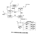
図3は、本発明の第1の実施形態に係るデータ処理方法を実施する署名検証側の構成(データ処理装置)100bを示すブロック図である。また、図4は、検証手段120の構成を示すブロック図である。
【0014】
図3に示されるように、署名検証側の構成100bは、検証手段120と、署名検証側の電子署名管理手段121と、署名生成側の構成100aから渡された電子署名管理テーブル103aの情報を記憶する署名検証側の記憶手段123とを有する。検証手段120は、入力端子21から入力された検証対象の画像データ(検証対象データ)に対して、電子署名データ及び画像補正情報を用いて検証処理を施し、検証結果を出力端子23から出力する。電子署名管理手段121は、入力端子31から入力された画像ID(検証対象データのID)を用いて、記憶手段123の電子署名管理テーブル103aから画像IDで特定された画像の電子署名データ及び画像補正情報を取り出し、検証手段120に出力する。
【0015】
図4に示されるように、検証手段120は、画像補正手段(データ補正手段)130と、署名検証手段131とを有する。画像補正手段130は、入力端子21から入力された検証対象の画像データに対し、電子署名管理手段121から入力端子20を経由して得られる画像補正情報を用いて画像の補正を行う。署名検証手段131は、画像補正手段130から出力される画像データに対し、電子署名管理手段121から入力端子22を経由して得られる電子署名データを用いて検証を行い、検証した結果を出力端子23から出力する。
【0016】
署名検証側の構成100bは、例えば、コンピュータシステムである。検証手段120及び電子署名管理手段121は、例えば、コンピュータシステムの演算装置である。記憶手段123は、例えば、コンピュータシステムの半導体メモリ又はハードディスク装置である。ただし、署名検証側の記憶手段123自体を、検証手段120及び電子署名管理手段121とは別の位置に配置された記憶装置、例えば、ネットワーク上のサーバの記憶装置とすることもできる。また、署名検証側の記憶手段123と署名生成側の記憶手段103とを、同じ記憶装置とすることもできる。
【0017】
[署名生成側の動作]
図1に示されるように、先ず、電子署名データを生成するターゲットとなる画像の画像データが、入力端子10を経由して署名手段101に入力される。また、電子署名データを生成するターゲットとなる画像を特定するデータである画像ID(例えば、ファイル名)が、入力端子11を経由して電子署名管理手段102へ入力される。
【0018】
図2に示される補正情報生成手段110は、入力端子10から入力された画像データに施される補正内容に基づいて画像データに関する画像補正情報を生成する。画像補正情報は、検証時に、署名生成時と同じ座標軸に画像を合わせるために用いられる。画像補正情報には、例えば、以下のような補正データの内の一つ以上が含まれる。ただし、以下の補正データは例示に過ぎず、他の補正データであってもよい。
(補正データi):画像の幅と高さの値
(補正データii):画像全体を2値化し、輪郭をトレースして得られるべクタデータ、及びべクタ交点の座標情報
【0019】
例えば、画像が拡大/縮小された場合に、改ざん検出を可能にするためには、画像補正情報として、画像の幅と高さの値(補正データi)を含めばよい。また、画像に回転等の操作が行われた場合に、改ざん検出を可能にするためには、画像補正情報として、べクタデータやべクタ交点の座標情報(補正データii)を含めばよい。
【0020】
図2に示される電子署名生成手段111は、例えば、セミフラジャイル電子透かし等に用いられる電子署名生成方法と同様の方法によって、電子署名データの生成を行うことができる。図5(a)に示されるように、署名を生成する画像に対して、DCT(離散コサイン変換)やウェーブレット(Wavelet)変換等の直交変換を行い、画像をDCT係数やウェーブレット係数等に変換する。得られた係数の中から、任意のペアを複数選び、それぞれのペアに対して、以下の式(1a)及び(1b)を用いて署名1ビットを生成する。画像全体の署名長は、ペアの数だけのビット数になる。
Sigi=0 (pi−qi≧0のとき) …(1a)
Sigi=1 (pi−qi<0のとき) …(1b)
ここで、pi及びqiは、同じサブバンド(subband)におけるウェーブレット係数であり、図5(a)に示されるように、ウェーブレット係数pi及びqiの配置は、ウェーブレット係数piとqiとの差分に相当するベクタνiによって決定される。また、Sigiは、ウェーブレット係数piとqiとの関係を示す署名ビットである。
【0021】
図1の電子署名管理手段102は、補正情報生成手段110から出力端子12を経由して得られる画像補正情報と、電子署名生成手段111から出力端子13を経由して得られる電子署名データと、入力端子11から得られる画像IDとを関連付けて、電子署名管理テーブル103aとして記憶手段103に保存する。電子署名管理テーブル103aには、画像IDに関連付けられた電子署名データ及び画像補正情報を保存し、画像IDに対応する電子署名データ及び画像補正情報を保存する機能及びこれらを取り出す機能を持つ。
【0022】
[署名検証側の動作]
図3に示されるように、検証対象となるターゲット画像の画像データを入力端子21へ、ターゲット画像の画像IDを入力端子31へ入力する。電子署名管理手段121は、入力端子31から入力された画像IDに対応する電子署名データ及び画像補正情報を、電子署名管理テーブル103aから取り出し、検証手段120へ出力する。
【0023】
図4の画像補正手段130は、入力端子22を経由して電子署名管理手段121から得られた画像補正情報を用いて、入力端子21から得られる画像データを補正する。記憶手段123に保管されている電子署名管理テーブル103aの画像補正情報には、例えば、以下のような補正データの内の一つ以上が含まれる。ただし、以下の補正データは例示に過ぎず、他の補正データであってもよい。
(補正データi):画像の幅と高さの値
(補正データii):画像全体を2値化し、輪郭をトレースして得られるべクタデータ、及びべクタ交点の座標情報
【0024】
例えば、画像が拡大/縮小された場合に、改ざん検出を可能にするためには、画像補正情報として、画像の幅と高さの値(補正データi)を含めばよい。この場合には、画像の補完フィルタや間引きフィルタを用いて、電子署名データを生成したときと同じ幅で、同じ高さの画像を生成する。
【0025】
また、画像に回転等の操作が行われた場合に、改ざん検出を可能にするためには、画像補正情報として、べクタデータやべクタ交点の座標情報(補正データii)を含めばよい。画像に回転等の操作が行われた場合には、例えば、以下のステップST1〜ST3の処理を行う。
(ステップST1):入力された画像を2値化し、輪郭をトレースしてベクタデータを取得し、そのべクタの交点座標を特徴点として得る。
(ステップST2):得られた特徴点に対し、回転、拡大/縮小を行って、元の画像と最もマッチする倍率と角度を得る。
(ステップST3):得られた倍率と角度により、アフィン変換等で画像をスケーリング/回転し、元の画像と同じサイズの画像を得る。
【0026】
図4の署名検証手段131は、画像補正手段130により得られる補正後の画像データを、署名管理手段121から得られる電子署名データを用いて検証し、検証結果を、出力端子23から出力する。検証は、例えば、セミフラジャイル電子透かし等に用いられる電子署名検証方法と同様の方法により行うことができる。図5(b)に示されるように、署名を検証する画像に対して、DCTやウェーブレット変換等の直交変換を行い、画像をDCT係数やウェーブレット係数等に変換する。得られた係数の中から、署名を生成した時と同じペアを複数選び、各ペアに対して、以下の条件(C1)〜(C3)を用いて署名を検証する。以下の条件(C1)〜(C3)のいずれかを満たす場合には、「改ざん無し」と判定でき、満たさない場合は、「改ざん有り」と判定できる。
条件(C1): p’i−q’i> M 且つ Sigi=0
条件(C2):|p’i−q’i|≦M (Sigiの値に関係なく)
条件(C3): p’i−q’i<−M 且つ Sigi=1
ここで、p’i及びq’iは、署名検証側(一般には、非可逆圧縮)において署名ビットSigiを生成するために使用される、ウェーブレット係数であり、図5(b)に示されるように、p’i及びq’iの配置は、署名生成側のものと同じベクタνiによって決定される。また、Mは、非可逆圧縮によって引き起こされる誤アラームを回避するためのマージン値である。
【0027】
上記式(1a)及び条件(C1)からわかるように、署名生成側でpi−qi≧0となり、署名検証側でp’i−q’i≦M(大小関係が反転)となれば、「改ざん有り」と判定される。また、上記式(1b)及び条件(C2),(C3),からわかるように、署名生成側でpi−qi<0となり、署名検証側でp’i−q’i>M(大小関係が反転)となれば「改ざん有り」と判定される。このように、マージン値Mを用いて改ざんの判定にある程度のマージンを持たせている理由は、非可逆圧縮等による画像の軽度な劣化を許容し(改ざん有りと判定せず)、悪意のある攻撃ような、大幅な変化だけを許容しない(改ざん有りと判定する)ためである。なお、署名生成方法及び署名検証方法は、上記した例に限定されず、他の方法を採用してもよい。
【0028】
[第1の実施形態の効果]
以上説明したように、第1の実施形態においては、署名生成側の構成100aが電子署名データ及び画像補正情報を生成して、これらを画像データに埋め込まずに記憶手段に保存する。また、第1の実施形態においては、署名検証側の構成100bが画像補正情報に基づいて画像データを補正してから署名検証側の電子署名データを生成し、これを署名生成側の電子署名データと比較することによって署名検証を行っている。このような処理を行う第1の実施形態に係るデータ処理方法によれば、署名生成側の電子署名データを画像データに埋め込まずに管理し、署名生成側の電子署名データ及び画像補正情報を署名検証側の構成に渡しているので、検証対象の画像データが拡大/縮小処理(スケーリング)を施されたものであったとしても、改ざんを高精度に検証することができる。
【0029】
≪第2の実施形態≫
[署名生成側の構成]
図6は、本発明の第2の実施形態に係るデータ処理方法を実施する署名生成側の構成(データ処理装置)200aを示すブロック図である。図6において、図1(第1の実施形態)の構成と同一又は対応する構成には、同じ符号を付す。
【0030】
図6に示されるように、署名生成側の構成200aは、署名手段101と、署名生成側の電子署名管理手段102と、署名生成側の記憶手段103と、画像ID発行手段(データID発行手段)104と、ID埋め込み手段(ID付加手段)105とを有する。画像ID発行手段104は、入力端子10から入力された画像に対して画像IDを生成する。ID埋め込み手段105は、画像ID発行手段104から得られる画像IDを、入力端子10から得られる画像データに埋め込み、画像IDが埋め込まれた後の画像データを出力端子50から出力する。署名手段101は、第1の実施形態の場合と同様の構成を有し、画像IDが埋め込まれた後の画像データについて、電子署名データ及び画像補正情報を計算して出力する。電子署名管理手段102は、画像ID発行手段104で発行された画像IDと、署名手段101から出力された電子署名データと、署名手段101から出力された画像補正情報とを関連づけた情報を電子署名管理テーブル103bとして記憶手段103に保存する。
【0031】
署名生成側の構成200aは、例えば、コンピュータシステムである。署名手段101、電子署名管理手段102、画像ID発行手段104、及びID埋め込み手段105は、例えば、コンピュータシステムの演算装置である。記憶手段103は、例えば、コンピュータシステムの半導体メモリ又はハードディスク装置である。ただし、記憶手段103自体を、署名手段101、電子署名管理手段102、画像ID発行手段104、及びID埋め込み手段105とは別の位置に配置された記憶装置、例えば、ネットワーク上のサーバの記憶装置とすることもできる。記憶手段103に保存された電子署名管理テーブル103aの情報は、例えば、ネットワーク等を経由して、以下に説明する署名検証側の構成200bに渡される。
【0032】
[署名検証側の構成]
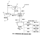
図7は、本発明の第2の実施形態に係るデータ処理方法を実施する署名検証側の構成(データ処理装置)200bを示すブロック図である。図7において、図2(第1の実施形態)の構成と同一又は対応する構成には、同じ符号を付す。
【0033】
図7に示されるように、署名検証側の構成200bは、検証手段120と、署名検証側の電子署名管理手段121と、ID検出手段122と、上記署名生成側の構成200aから渡された電子署名管理テーブル103aを記憶する署名検証側の記憶手段123とを有する。ID検出手段122は、入力端子21から検証対象の画像データ(検証対象データ)から画像IDを抽出して出力する。検証手段120は、第1の実施形態の場合と同様の構成を有し、入力端子21から入力された検証対象の画像データに対して、電子署名データ及び画像補正情報を用いて画像を検証し、検証結果を出力端子23から出力する。電子署名管理手段121は、ID検出手段122で検出された画像IDを用いて、記憶手段123の電子署名管理テーブル103bから画像IDで特定された画像の電子署名データ及び画像補正情報を取り出し、検証手段120に出力する。
【0034】
署名検証側の構成200bは、例えば、コンピュータシステムである。検証手段120、電子署名管理手段121、及びID検出手段122は、例えば、コンピュータシステムの演算装置である。記憶手段123は、例えば、コンピュータシステムの半導体メモリ又はハードディスク装置である。ただし、署名検証側の記憶手段123自体を、検証手段120、電子署名管理手段121、及びID検出手段122とは別の位置に配置された記憶装置、例えば、ネットワーク上のサーバの記憶装置とすることもできる。また、署名検証側の記憶手段123と署名生成側の記憶手段103とを、同じ記憶装置とすることもできる。
【0035】
[署名生成側の動作]
図6に示されるように、画像ID発行手段104は、画像を識別するためにユニークな(固有の)画像IDを生成し、ID埋め込み手段105及び電子署名管理手段102に出力する。画像IDは、画像を特定できる内容であればよく、ランダムな値、コンテンツの内容、タイムスタンプ等から生成することができる。また、画像ID発行手段104は、画像ID以外の情報、例えば、画像に関するコメントや時刻情報等を画像IDと関連づけて生成してもよい。この場合、コメントや時刻情報等を、電子署名管理テーブル103bに保存してもよく、また、電子透かしのメッセージとしてID埋め込み手段105によって画像に埋め込んでもよい。
【0036】
ID埋め込み手段105は、入力端子10から得られた画像データに、画像ID発行手段104から得られる画像IDを埋め込み、ID埋め込み後の画像データを画像出力端子50へ出力する。また、ID埋め込み後の画像データを署名手段101へ出力する。ID埋め込み手段105は、例えば、著作権保護に用いられるロバスト(robust)な電子透かしを用いる。ロバストな電子透かしとしては、例えば、以下のようなステップからなる方式を用いることができるが、特に方式は制限されない。
(ステップST11):埋め込む画像IDデータとメッセージデータに対して、BCH符号やターボ符号等のエラー訂正符号を用いて符号化を行う。
(ステップST12):ウェーブレット変換やDCT等による周波数変換後の係数を、やや大きな量子化係数にて量子化し、量子化後の係数のLSBビットプレーンに、エラー訂正符号化後のデータを繰り返し埋め込む。
【0037】
ただし、画像IDは、必ずしも電子透かしとして画像データに埋め込まれる必要はなく、画像ファイルのヘッダのコメント領域等に、画像IDを記録してもよい。また、署名手段101及び電子署名管理手段102の動作は、上記第1の実施形態の場合と同様である。
【0038】
[署名検証側の動作]
図7に示されるように、署名を検証するターゲット画像の画像データを入力端子21へ入力する。図7に示されるように、ID検出手段122は、入力端子21から入力された画像データから画像IDを検出する。画像IDが、画像データにロバストな電子透かしとして埋め込まれている場合には、これをロバストな電子透かしの検出方法を用いて検出する。この場合の検出アルゴリズムは、特に限定されないが、例えば、以下のようなステップからなる方法を用いることができる。
(ステップST21):画像に対して回転や解像度変換を行い、複数解像度、複数角度の画像に対して以下のステップST22〜ST25の処理を行う。
(ステップST22):ウェーブレット変換やDCT等による周波数変換後の係数を、ID埋め込み手段105で用いた量子化係数にて量子化し、量子化後の係数のLSBビットプレーンから、データを複数個取り出す。
(ステップST23):取り出した複数のデータに対して、ビット単位で最頻値を求める。
(ステップST24):最頻値で構成されたデータに対し、エラー訂正符号でデコードをし、元の画像IDとメッセージを出力する。
(ステップST25):上記ステップST22〜ST24の処理を複数回行い、最もエラーの少ない場合の画像IDを出力値とする。
ただし、電子透かしを用いずに、画像ファイルのヘッダのコメント領域等に、画像IDを記録した場合には、画像ファイルのヘッダから画像IDを取得する。
【0039】
なお、ID検出手段122によって得られた画像IDは、電子署名管理手段121へ出力する。また、検証手段101及び電子署名管理手段102の動作は、上記第1の実施形態の場合と同様である。
【0040】
[第2の実施形態の効果]
以上説明したように、第2の実施形態においては、署名生成側の構成200aが電子署名データ及び画像補正情報を生成して、これらを画像データに埋め込まずに記憶手段に保存する。また、第2の実施形態においては、署名生成側の構成200aが画像IDを画像データに付加する(埋め込む場合と、単に付加する場合がある)。さらに、第2の実施形態においては、署名検証側の構成200bが画像データから画像IDを取得し、取得した画像IDに対応する画像補正情報に基づいて画像データを補正してから署名検証側の電子署名データを生成し、これを署名生成側の電子署名データと比較することによって署名検証を行っている。このような処理を行う第2の実施形態に係るデータ処理方法によれば、電子署名データを画像データに埋め込まずに管理し、署名生成側の電子署名データ及び画像補正情報を署名検証側の構成に渡しているので、検証対象の画像データが拡大/縮小処理(スケーリング)を施されたものであったとしても、改ざんを高精度に検証することができる。
【0041】
また、第2の実施形態において画像データと画像IDとをロバストな電子透かしによって結合させた場合には、画像IDと画像データとの関連付けが容易になり、また、第三者によって画像IDと画像データとのリンクが切られるという事態が発生し難くなる。
【0042】
さらに、第2の実施形態においては、画像データと画像IDが結合されているので、自動的に電子署名データと画像補正情報を取得することが可能となり、画像の改ざん検出の自動化が可能になる。
【0043】
≪第3の実施形態≫
[署名生成側の構成]
図8は、本発明の第3の実施形態に係るデータ処理方法を実施する署名生成側の構成(データ処理装置)300aを示すブロック図である。図8において、図6(第2の実施形態)の構成と同一又は対応する構成には、同じ符号を付す。
【0044】
図8に示されるように、署名生成側の構成300aは、署名手段101(図6)に代えて電子署名生成手段111を有する点が、図6(第2の実施形態)に示される署名生成側の構成200aと相違する。また、図8に示されるように、署名生成側の構成300aは、電子署名管理テーブル103cに画像補正情報を保存しない点が、図6(第2の実施形態)に示される署名生成側の構成200aと相違する。これらの点以外については、第3の実施形態の署名生成側の構成300aは、第2の実施形態の署名生成側の構成200aと同様である。
【0045】
[署名検証側の構成]
図9は、本発明の第3の実施形態に係るデータ処理方法を実施する署名検証側の構成(データ処理装置)300bを示すブロック図である。図9において、図7(第2の実施形態)の構成と同一又は対応する構成には、同じ符号を付す。
【0046】
図9に示されるように、第3の実施形態の署名検証側の構成300bは、ID検出手段122が画像補正情報を計算し、検証手段120に対して画像補正情報を出力する点、電子署名管理テーブル103cが画像補正情報を含まない点、及び、検証手段120による署名検証のためのデータ処理の内容が、図7(第2の実施形態)に示される署名検証側の構成200bと相違する。これらの点以外については、第3の実施形態の署名検証側の構成300bは、第2の実施形態の署名検証側の構成200bと同じである。
【0047】
[署名生成側の動作]
図8に示されるように、画像ID発行手段104は、画像を識別するためにユニークな(固有の)画像IDを生成し、ID埋め込み手段105及び電子署名管理手段102に出力する。ID埋め込み手段105は、入力端子10から得られた画像データに、画像ID発行手段104から得られる画像IDを埋め込み、ID埋め込み後の画像データを画像出力端子50へ出力する。画像ID発行手段104、ID埋め込み手段105、及び電子署名管理手段102の動作は、第2の実施形態における動作と同様である。
【0048】
電子署名生成手段111は、ID埋め込み手段105から得られる画像データに対して、第1の実施形態(図2の電子署名生成手段111)と同様の方法で電子署名データを生成し、電子署名管理手段102に出力する。図8に示されるように、電子署名管理手段102は、画像ID及び電子署名データを含む電子署名管理テーブル103cを記憶手段103に保存する。
【0049】
[署名検証側の動作]
図9に示されるように、ID検出手段122は、入力端子21から入力された画像データから画像IDを検出する。画像IDは、画像データにロバストな電子透かしとして埋め込まれているため、これをロバストな電子透かしの検出方法を用いて検出する。この場合の検出アルゴリズムは、特に限定されないが、例えば、以下のようなステップからなる方法を用いることができる。
(ステップST31):画像に対して回転や解像度変換を行い、複数解像度、複数角度の画像に対して以下のステップST32〜ST35の処理を行う。
(ステップST32):ウェーブレット変換やDCT等による周波数変換後の係数を、ID埋め込み手段105で用いた量子化係数にて量子化し、量子化後の係数のLSBビットプレーンから、データを複数個取り出す。
(ステップST33):取り出した複数のデータに対して、ビット単位で最頻値を求める。
(ステップST34):最頻値で構成されたデータに対し、エラー訂正符号でデコードし、元の画像IDとメッセージを出力する。
(ステップST35):上記ステップST32〜ST34の処理を複数回行い、最もエラーの少ない場合の画像IDを出力値とする。
【0050】
このようにして得られた画像IDを電子署名管理手段121へ出力し、画像IDを検出した際の解像度/回転角度を、画像補正情報として検証手段120へ出力する。検証手段120では、第2の実施形態の場合のように画像補正情報を電子署名管理手段121から得るのではなく、画像補正情報をID検出手段122から取得する。検証手段120は、ID検出手段122から出力される画像補正情報を用いて画像を補正し、その後、署名検証を行う。署名検証の方法は、第2の実施形態の場合と同様である。
【0051】
[第3の実施形態の効果]
以上説明したように、第3の実施形態においては、署名生成側の構成300aが電子署名データを生成して、これらを画像データに埋め込まずに記憶手段に保存する。また、第3の実施形態においては、署名生成側の構成300aが画像IDを画像データに電子透かしとして埋め込む。さらに、第3の実施形態においては、署名検証側の構成300bが画像データから画像IDを取得し、画像IDを取得した際の情報から画像補正情報を取得する。このような処理を行う第3の実施形態に係るデータ処理方法によれば、電子署名データを画像データに埋め込まずに管理し、署名生成側の電子署名データを署名検証側の構成に渡し、画像補正情報を画像ID検出処理を通して取得しているので、検証対象の画像データが拡大/縮小処理(スケーリング)を施されたものであったとしても、改ざんを高精度に検証することができる。
【0052】
また、第3の実施形態によれば、ロバストな電子透かし検出時に得られる回転情報/解像度情報から、画像補正情報を取得しているので、電子署名管理テーブルが画像補正情報を管理する必要がなくなる。
【0053】
≪第4の実施形態≫
[署名生成側の構成]
図10は、本発明の第4の実施形態に係るデータ処理方法を実施する署名生成側の構成(データ処理装置)400aを示すブロック図である。図10において、図8(第3の実施形態)の構成と同一又は対応する構成には、同じ符号を付す。
【0054】
図10に示されるように、署名生成側の構成400aは、入力端子10から入力される画像データについての画像補正情報を生成する補正情報生成手段110と、補正情報生成手段110から出力される画像補正情報を画像IDと一緒に画像に埋め込むID埋め込み手段105を有する。これ以外の点について、第4の実施形態の署名生成側の構成400aは、第3の実施形態の署名生成側の構成300aと同様である。
【0055】
[署名検証側の構成]
図11は、本発明の第4の実施形態に係るデータ処理方法を実施する署名検証側の構成(データ処理装置)400bを示すブロック図である。図11において、図9(第3の実施形態)の構成と同一又は対応する構成には、同じ符号を付す。
【0056】
図11に示されるように、署名検証側の構成400bは、ID検出手段122から画像IDと一緒に埋め込まれた画像補正情報を出力し、検証手段120に入力する。この点以外については、第4の実施形態の署名検証側の構成400bは、第3の実施形態の署名検証側の構成300bと同様である。
【0057】
[署名生成側の動作]
図10に示されるように、画像ID発行手段104は、画像を識別するためにユニークな(固有の)画像IDを生成し、ID埋め込み手段105及び電子署名管理手段102に出力する。補正情報生成手段110は、入力端子10から入力された画像データについての画像補正情報を生成し出力する。ID埋め込み手段105は、入力端子10から入力される画像データに、画像ID発行手段104から得られる画像IDと、補正情報生成手段110から得られる画像補正情報を、上記実施形態で説明した電子透かしにより埋め込む。上記以外の点については、第4の実施形態の署名生成側の構成400aの動作は、第3の実施形態の署名生成側の構成300aの動作と同様である。
【0058】
[署名検証側の動作]
図11に示されるように、ID検出手段122は、入力端子21から検出された画像データから埋め込まれた画像IDと画像補正情報を検出する。このようにして得られた画像IDを電子署名管理手段121へ出力し、画像ID及び画像補正情報を検出して検証手段120へ出力する。検証手段120は、ID検出手段122から出力される画像補正情報を用いて画像を補正し、その後、署名検証を行う。署名検証の方法は、第2又は第3の実施形態の場合と同様である。
【0059】
[第4の実施形態の効果]
以上説明したように、第4の実施形態においては、署名生成側の構成400aが電子署名データを生成して、これらを画像データに埋め込まずに記憶手段に保存する。また、第4の実施形態においては、署名生成側の構成400aが画像ID及び画像補正情報を画像データに付加する(埋め込む場合と、単に付加する場合がある)。さらに、第4の実施形態においては、署名検証側の構成400bが画像データから画像ID及び画像補正情報を取得する。このような処理を行う第4の実施形態に係るデータ処理方法によれば、電子署名データを画像データに埋め込まずに管理し、電子署名データを署名検証側の構成に渡し、画像補正情報を画像ID検出処理を通して取得しているので、検証対象の画像データが拡大/縮小処理(スケーリング)を施されたものであったとしても、改ざんを高精度に検証することができる。
【0060】
また、第3の実施形態におけるように、ID検出手段122においてロバストな電子透かしから回転情報や解像度情報を取り出す必要がない。このため、第4の実施形態においては、画像補正情報を取得するために、汎用のロバスト電子透かしコンポーネントを使用することができる(即ち、ロバスト電子透かしコンポーネントのカスタマイズが不要である)。また、第4の実施形態においては、電子署名管理手段121や、電子署名管理テーブル103dが、画像補正情報を管理する必要がなくなる。
【0061】
≪第5の実施形態≫
[署名生成側の構成]
図12は、本発明の第5の実施形態に係るデータ処理方法を実施する署名生成側の構成(データ処理装置)の電子署名生成手段の動作を示す説明図である。第5の実施形態における署名生成側の構成は、上記第1〜第4の実施形態における署名生成側の構成のいずれかと同様の構成を持つ。第5の実施形態は、電子署名生成手段111によるデータ処理内容が、上記第1〜第4の実施形態のものと相違する。
【0062】
図12に示されるように、第5の実施形態の電子署名生成手段111は、入力された元の画像データから電子署名データを生成するだけではなく、入力された元の画像データをダウンサンプリングして、元の画像とは異なる解像度変更された画像データを一つ以上生成し、解像度変更された画像についても電子署名データを生成する。従って、電子署名管理テーブル103a〜103dの署名データは、図12の下側に示されるように、解像度情報と電子署名データの組合わせ(例えば、▲1▼画像サイズ+電子署名1、▲2▼解像度情報1+電子署名2、▲3▼解像度情報2+電子署名3、等)を複数個含むことになる。
【0063】
[署名検証側の構成]
図13は、本発明の第5の実施形態に係るデータ処理方法を実施する署名検証側の構成(データ処理装置)の署名検証手段の動作を示す説明図である。第5の実施形態における署名検証側の構成は、上記第1〜第4の実施形態における署名検証側の構成のいずれかと同様の構成を持つ。第5の実施形態は、署名検証手段131によるデータ処理内容が、上記第1〜第4の実施形態のものと相違する。
【0064】
図13に示されるように、第5の実施形態の署名検証手段131は、入力された検証対象の画像データの解像度が、電子署名管理テーブル103a〜103dの電子署名データとして保存されている解像度と異なる場合には、検証対象の画像データをダウンサンプリングして、電子署名管理テーブル103a〜103dの電子署名データとして保存されている解像度の一つに一致させる。その後、電子署名データの検証を行う。
【0065】
[署名生成側の動作]
図12に示されるように、電子署名生成手段は、入力された画像データをダウンサンプリングし、複数の解像度の画像を生成する。ダウンサンプリングの方法は、通常のダウンサンプリングフィルタを用いればよく、特定のものに限定されない。各解像度の画像に対して、電子署名を生成する。電子署名の生成方法は、第1の実施形態の場合と同じ方法を用いることができる。
【0066】
各解像度の電子署名データを、解像度情報と多重化又は関連づけて出力する。解像度情報には、dpi情報(単位長さ当たりのドット数)等のほか、元の画像と解像度変更後の画像とのサイズの比率、ダウンサンプリング後の画像サイズ等を用いることができる。これ以外の点については、第5の実施形態の署名生成側の構成は、第1〜第4の実施形態の署名生成側の構成100a,200a,300a,400aと同様である。
【0067】
[署名検証側の動作]
図13に示されるように、署名検証手段は、入力された画像の画像サイズを用いて、使用する電子署名を選択する。選択方法は、例えば、入力画像よりも小さくい解像度で生成された1又は複数の電子署名の内の、最も大きい解像度で生成された電子署名を使用する。
【0068】
例えば、図13に示されるように、電子署名が「電子署名1」「電子署名2」「電子署名3」の3組あり、入力画像よりも小さくい解像度で生成された電子署名の内の、最も大きい解像度で生成された電子署名が「電子署名2」である場合、電子署名2を用いる。署名検証時は、入力画像をリサンプリングして、使用する電子署名が生成された画像サイズに拡大/縮小を行う電子署名の検証自体は、例えば、第1の実施形態で説明した方法と同じ方法を用いることができる。これ以外の点については、第5の実施形態の署名検証側の構成は、第1〜第4の実施形態の署名検証側の構成100b,200b,300b,400bと同様である。
【0069】
[第5の実施形態の効果]
セミフラジャイル電子署名では、署名が生成された解像度よりも低い解像度(サイズが小さい)画像を検証しようとすると、検証対象の画像をアップサンプリングする必要がある。しかし、この際、検証対象画像には、電子署名生成時に保持していた解像度以下の情報量しか画像に含まれていないため、誤検出(改ざんしていないにもかかわらず「改ざん有り」と検出されること)が発生する。また、考え得る最低解像度を用いて電子署名を生成すると、その解像度のレベルでしか、改ざんを検出できず、その解像度よりも高い解像度の画像に存在する細かな情報が改ざんされたとしても、「改ざん有り」と検出することができずに、検出精度が悪化する。第5の実施形態によれば、各解像度表現での電子署名を保持しておくことにより、画像のサイズが変更された際に、最も適した電子署名を使用することで、誤検出を低減し、また、改ざん検出率を上げることができ、全体として検出精度を大幅に向上させることができる。
【0070】
[第5の実施形態の変形例]
第5の実施形態は、解像度変換を、図14及び図15に示されるように、ウェーブレット変換と同時に行うことができる。電子署名生成や画像圧縮を行う際のウェーブレット変換中に、順次生成される各LL成分(低周波成分)から電子署名データを生成すれば、フィルタ処理等のコストを低減することができる。また、次世代の圧縮画像形式として規格されているJPEG2000と互換性のあるウェーブレット変換を用いれば、JPEG2000圧縮に対する耐性が向上する。
≪他の応用≫
【0071】
上記した各実施形態においては、署名生成対象のデータ及び検証対象のデータが画像データである場合を説明したが、本発明は、音声データ等の他のデータに対しても適用可能である。
【0072】
また、上記した各実施形態において、ID埋め込み手段及びID検出手段は、一般的なロバストな電子透かしならば、どのような方式を使用してもよい。同様に、署名生成手段及び検証手段も、一般的にセミフラジャイルな電子署名であれば、どのような方式のものを使用してもよい。
【0073】
さらに、上記した各実施形態において、画像補正情報が画像のサイズ等の情報である場合を説明したが、元の画像のスケールを復元できるデータであれば、どのようなデータであってもよい。
【0074】
さらにまた、上記した各実施形態において、電子署名管理手段や署名管理テーブルは、特に記録媒体や構成形態を限定する必要はなく、画像IDと電子署名データの関連性を保持できるものならば、何でもよい。例えば、HDD等のストレージデバイスやファイルシステム、ネットワークサービス、無線サービス、リムーバブルメディア等を用いることができる。
【0075】
また、上記した各実施形態において、署名検証時に画像をスケーリングする場合を説明したが、必ずしもスケーリングが必要とは限らない。例えば、まったくサイズが変更されていない画像に対して、スケーリングは不要である。
【0076】
さらに、上記した各実施形態において、署名検証時に画像をスケーリングすると記載したが、特に一括でスケーリングする必要はない。また、画像でなく、電子署名検証内部で使用するDCT後の計数やウェーブレット変換後の係数を逐次スケーリングして処理してもよい。
【0077】
さらにまた、上記第2乃至第5の実施形態において、画像ID発行手段が署名生成側として含まれているが、画像ID発行手段は署名生成器の中にある必要はなく、外部から画像IDを与えてもよい。
【0078】
また、上記した各実施形態において、各手段は、同一の装置内にある必要はなく、各手段間のデータの伝送は、PCの内部バスや外部バス、ネットワークや無線伝送、ストレージデバイスによる蓄積やりムーバブルメディア等による運搬等、特に限定しない。
【0079】
さらに、署名生成側の構成がコンピュータシステムである場合には、署名生成側の動作は、コンピュータシステムにインストールされたアプリケーションプログラムに従って実行させることができる。このアプリケーションプログラムのインストール方法には、インストール用プログラムが記録された記憶媒体からのインストールやインターネットを経由したダウンロード等の方法がある。同様に、署名検証側の構成がコンピュータシステムである場合には、署名生成側の動作は、コンピュータシステムにインストールされたアプリケーションプログラムに従って実行させることができる。このアプリケーションプログラムのインストール方法には、インストール用プログラムが記録された記憶媒体からのインストールやインターネットを経由したダウンロード等の方法がある。
【0080】
【発明の効果】
以上説明したように、本発明によれば、署名生成側の構成が、電子署名データを管し、署名検証側の構成が、画像ID及び画像補正情報を取得し、画像補正情報に基づいて画像データを元の画像に戻す補正をしてから検証を行っている。このため、署名生成側の構成において行われた画像拡大/縮小のような補正を改ざんとはみなさないので、画像がスケーリングされた場合であっても改ざん高精度に検証することができるという効果がある。
【図面の簡単な説明】
【図1】本発明の第1の実施形態に係るデータ処理方法を実施する署名生成側の構成(データ処理装置)を示すブロック図である。
【図2】図1及び図6の署名手段の構成を示すブロック図である。
【図3】本発明の第1の実施形態に係るデータ処理方法を実施する署名検証側の構成(データ処理装置)を示すブロック図である。
【図4】図3、図7、図9、及び図11の検証手段の構成を示すブロック図である。
【図5】(a)及び(b)はそれぞれ、本発明の第1〜第5の実施形態に係る署名生成処理及び署名検証処理を示す説明図である。
【図6】本発明の第2の実施形態に係るデータ処理方法を実施する署名生成側の構成(データ処理装置)を示すブロック図である。
【図7】本発明の第2の実施形態に係るデータ処理方法を実施する署名検証側の構成(データ処理装置)を示すブロック図である。
【図8】本発明の第3の実施形態に係るデータ処理方法を実施する署名生成側の構成(データ処理装置)を示すブロック図である。
【図9】本発明の第3の実施形態に係るデータ処理方法を実施する署名検証側の構成(データ処理装置)を示すブロック図である。
【図10】本発明の第4の実施形態に係るデータ処理方法を実施する署名生成側の構成(データ処理装置)を示すブロック図である。
【図11】本発明の第4の実施形態に係るデータ処理方法を実施する署名検証側の構成(データ処理装置)を示すブロック図である。
【図12】本発明の第5の実施形態における電子署名生成手段の動作を示す説明図である。
【図13】本発明の第5の実施形態における電子署名検証手段の動作を示す説明図である。
【図14】本発明の第5の実施形態の変形例における電子署名生成手段の動作を示す説明図である。
【図15】本発明の第5の実施形態の変形例における電子署名検証手段の動作を示す説明図である。
【図16】従来のフラジャイル電子透かしの埋め込み動作を示す説明図である。
【図17】従来のフラジャイル電子透かしの検証動作を示す説明図である。
【符号の説明】
100a,200a,300a,400a 署名生成側の構成(データ処理装置)、
100b,200b,300b,400b 署名検証側の構成(データ処理装置)、
101 署名手段、
102 署名生成側の電子署名管理手段、
103 署名生成側の記憶手段、
103a,…,103d 電子署名管理テーブル、
104 画像ID発行手段(データID発行手段)、
105 ID埋め込み手段(ID付加手段)、
110 補正情報生成手段、
111 電子署名生成手段、
120 検証手段、
121 署名検証側の電子署名管理手段、
122 ID検出手段、
123 署名検証側の記憶手段、
130 画像補正手段(データ補正手段)、
131 署名検証手段。[0001]
TECHNICAL FIELD OF THE INVENTION
The present invention relates to a data processing method and a data processing apparatus for generating electronic signature data from image data or the like by using a configuration on a signature generation side and detecting whether the image data or the like has been tampered with the electronic signature data using a configuration on a signature verification side. It is about.
[0002]
[Prior art]
As a method for detecting falsification of image data, there is a method of embedding digital signature data in image data using digital watermark technology. For example, when a fragile digital watermark is embedded in a bitmap image, a hash value is calculated from a bit-plane other than the LSB (least significant bit) as shown in FIG. There is a method in which a hash value encrypted by an encryption method is embedded in an LSB as digital signature data. When verifying the digital signature data, as shown in FIG. 17, the hash value generated at the time of embedding the digital watermark is decrypted and extracted from the LSB portion of the image data in which the digital signature data is embedded. , A hash value is calculated by the same algorithm as the embedding side, and if both hash values match, it is determined that the image data has not been tampered with (for example, see Non-Patent
[0003]
Further, in semi-fragile (semi-fragile) digital watermarking, (i) digital signature data is generated so as to be invariable to some extent even if an image is irreversibly compressed, and (ii) the digital signature data is slightly more MSB than LSB. (Most significant bit) By embedding in the part closer to (most significant bit) and (iii) giving a width to the image estimated from the digital signature data, it is prohibited to change and use the contents of the image data itself, Changes by lossless compression are allowed.
[0004]
[Non-patent document 1]
Koko Matsui, "Basics of Digital Watermarking" (Morikita Publishing Co., Ltd.), pp. 38-48
[Patent Document 1]
JP 2001-42768 A (FIGS. 1 to 4)
[0005]
[Problems to be solved by the invention]
However, if the image size is changed in the above-described conventional falsification detection method, the embedded digital signature data cannot be correctly extracted, and the original image data of the resized image data cannot be obtained. Performing signature verification (ie, comparing digital signature data embedded in image data to be verified with digital signature data generated from the image data to be verified using the same algorithm as the signature generation side) Could not. In other words, in the above-described conventional tampering detection method, the image size (width and height in pixel units) on the signature generation side and the image size on the signature verification side must be the same, and the image size is changed. In such a case, even if the data has not been tampered with, the result of the verification is “tampered”, and there has been a problem that tampering cannot be verified correctly.
[0006]
Therefore, the present invention has been made to solve the above-described problems of the related art, and an object of the present invention is to manage digital signature data without embedding it in data to be verified and to acquire data correction information. Accordingly, it is an object of the present invention to provide a data processing method and a data processing device capable of verifying tampering with high accuracy even if the data to be verified has been subjected to enlargement / reduction processing.
[0007]
[Means for Solving the Problems]
The data processing method executed by the signature generation side configuration according to the present invention includes a step in which the signature generation side configuration receives the input data and a data ID for specifying the input data, and the signature generation side configuration based on the input data. Generating electronic signature data; generating data correction information based on the correction content applied to the input data; data ID specifying the input data; electronic signature data on the signature generation side; And storing an electronic signature management table including at least one combination of data correction information.
[0008]
The data processing method executed by the signature verification-side configuration of the present invention, wherein the signature verification-side configuration receives the data to be verified and a data ID that specifies the data to be verified. Obtaining data correction information corresponding to the data ID specifying the data to be verified and the digital signature data on the signature generation side from the obtained electronic signature management table; and Correcting the data; generating digital signature data on the signature verification side from the corrected data to be verified; comparing the digital signature data on the signature generation side with the digital signature data on the signature verification side; Determining whether the verification target data has been tampered with based on the result.
[0009]
BEST MODE FOR CARRYING OUT THE INVENTION
<< 1st Embodiment >>
[Configuration of signature generation side]
FIG. 1 is a block diagram illustrating a configuration (data processing device) 100a on the signature generation side that performs a data processing method according to the first embodiment of the present invention. FIG. 2 is a block diagram showing the configuration of the signature unit 101.
[0010]
As shown in FIG. 1, the configuration 100a on the signature generation side includes a signature unit 101, an electronic
[0011]
As shown in FIG. 2, the signature unit 101 includes a correction
[0012]
The configuration 100a on the signature generation side is, for example, a computer system. The signature unit 101 and the electronic
[0013]
[Configuration of signature verification side]
FIG. 3 is a block diagram showing a configuration (data processing device) 100b on the signature verification side that performs the data processing method according to the first embodiment of the present invention. FIG. 4 is a block diagram showing a configuration of the
[0014]
As shown in FIG. 3, the signature verification-side configuration 100b transmits the information of the electronic signature management table 103a passed from the
[0015]
As shown in FIG. 4, the
[0016]
The configuration 100b on the signature verification side is, for example, a computer system. The
[0017]
[Operation of signature generation side]
As shown in FIG. 1, first, image data of an image serving as a target for generating digital signature data is input to the signature unit 101 via the
[0018]
The correction
(Correction data i): width and height values of the image
(Correction data ii): Vector data obtained by binarizing the entire image and tracing the contour, and coordinate information of vector intersections
[0019]
For example, in order to enable tampering detection when the image is enlarged / reduced, the image correction information may include the width and height values (correction data i) of the image. Further, in order to enable tampering detection when an operation such as rotation is performed on an image, vector correction data and coordinate information of a vector intersection (correction data ii) may be included as image correction information.
[0020]
The digital
Sig i = 0 (p i -Q i ≧ 0) (1a)
Sig i = 1 (p i -Q i <0) (1b)
Where p i And q i Is a wavelet coefficient in the same subband (subband), and as shown in FIG. i And q i Is arranged by the wavelet coefficient p i And q i Vector ν corresponding to the difference i Is determined by Also, Sig i Is the wavelet coefficient p i And q i Is a signature bit indicating the relationship with
[0021]
The electronic
[0022]
[Operation of the signature verification side]
As shown in FIG. 3, the image data of the target image to be verified is input to the
[0023]
4 corrects image data obtained from the
(Correction data i): width and height values of the image
(Correction data ii): Vector data obtained by binarizing the entire image and tracing the contour, and coordinate information of vector intersections
[0024]
For example, in order to enable tampering detection when the image is enlarged / reduced, the image correction information may include the width and height values (correction data i) of the image. In this case, an image having the same width and the same height as when digital signature data is generated is generated by using an image complement filter or a thinning filter.
[0025]
Further, in order to enable tampering detection when an operation such as rotation is performed on an image, vector correction data and coordinate information of a vector intersection (correction data ii) may be included as image correction information. When an operation such as rotation is performed on the image, for example, the following steps ST1 to ST3 are performed.
(Step ST1): The input image is binarized, the outline is traced to acquire vector data, and the intersection coordinates of the vector are obtained as feature points.
(Step ST2): The obtained feature points are rotated and enlarged / reduced to obtain a magnification and an angle that best match the original image.
(Step ST3): Based on the obtained magnification and angle, the image is scaled / rotated by affine transformation or the like to obtain an image of the same size as the original image.
[0026]
4 verifies the corrected image data obtained by the
Condition (C1): p ′ i -Q ' i > M and Sig i = 0
Condition (C2): | p ' i -Q ' i | ≦ M (Sig i Regardless of the value of
Condition (C3): p ′ i -Q ' i <-M and Sig i = 1
Where p ' i And q ' i Is the signature bit Sig on the signature verification side (generally, lossy compression). i Are the wavelet coefficients used to generate, and as shown in FIG. i And q ' i Is the same vector ν as that on the signature generation side. i Is determined by M is a margin value for avoiding false alarms caused by lossy compression.
[0027]
As can be seen from the above equation (1a) and condition (C1), p on the signature generation side i -Q i ≧ 0, and p ′ on the signature verification side i -Q ' i If ≦ M (the magnitude relationship is reversed), it is determined that “falsification has occurred”. As can be seen from the above equation (1b) and the conditions (C2) and (C3), p i -Q i <0, and the signature verification side p ′ i -Q ' i If> M (the magnitude relationship is reversed), it is determined that “falsification has occurred”. As described above, the reason for giving a certain margin to the falsification determination using the margin value M is that slight deterioration of the image due to irreversible compression or the like is allowed (it is not determined that falsification has occurred), and malicious processing is performed. This is because only a significant change such as an attack is not permitted (it is determined that there is tampering). Note that the signature generation method and the signature verification method are not limited to the examples described above, and other methods may be employed.
[0028]
[Effects of First Embodiment]
As described above, in the first embodiment, the configuration 100a on the signature generation side generates digital signature data and image correction information, and saves them in the storage unit without embedding them in the image data. Further, in the first embodiment, the signature verification-side configuration 100b corrects the image data based on the image correction information, and then generates the signature verification-side electronic signature data. The signature is verified by comparing with. According to the data processing method according to the first embodiment that performs such processing, the digital signature data on the signature generation side is managed without being embedded in the image data, and the digital signature data and the image correction information on the signature generation side are signed. Since the data is passed to the configuration on the verification side, tampering can be verified with high accuracy even if the image data to be verified has been subjected to enlargement / reduction processing (scaling).
[0029]
<< 2nd Embodiment >>
[Configuration of signature generation side]
FIG. 6 is a block diagram illustrating a configuration (data processing device) 200a on the signature generation side that performs the data processing method according to the second embodiment of the present invention. 6, the same reference numerals are given to the same or corresponding components as those in FIG. 1 (first embodiment).
[0030]
As shown in FIG. 6, the configuration 200a on the signature generation side includes a signature unit 101, an electronic
[0031]
The configuration 200a on the signature generation side is, for example, a computer system. The signature unit 101, the electronic
[0032]
[Configuration of signature verification side]
FIG. 7 is a block diagram illustrating a configuration (data processing device) 200b on the signature verification side that performs the data processing method according to the second embodiment of the present invention. 7, the same reference numerals are given to the same or corresponding components as those in FIG. 2 (first embodiment).
[0033]
As shown in FIG. 7, the signature verification-side configuration 200b includes a
[0034]
The configuration 200b on the signature verification side is, for example, a computer system. The
[0035]
[Operation of signature generation side]
As shown in FIG. 6, the image
[0036]
The
(Step ST11): The image ID data and the message data to be embedded are encoded using an error correction code such as a BCH code or a turbo code.
(Step ST12): The coefficient after frequency transformation by wavelet transformation or DCT is quantized with a slightly larger quantization coefficient, and data after error correction encoding is repeatedly embedded in the LSB bit plane of the quantized coefficient.
[0037]
However, the image ID does not necessarily need to be embedded in the image data as a digital watermark, and the image ID may be recorded in a comment area or the like of the header of the image file. The operations of the signature unit 101 and the electronic
[0038]
[Operation of the signature verification side]
As shown in FIG. 7, image data of a target image whose signature is to be verified is input to an
(Step ST21): Rotation and resolution conversion are performed on the image, and the following steps ST22 to ST25 are performed on an image having a plurality of resolutions and a plurality of angles.
(Step ST22): The coefficients after frequency transformation by wavelet transformation or DCT are quantized by the quantization coefficients used by the ID embedding means 105, and a plurality of data are extracted from the LSB bit plane of the quantized coefficients.
(Step ST23): A mode value is obtained for each of the plurality of extracted data in bit units.
(Step ST24): The data composed of the most frequent value is decoded with the error correction code, and the original image ID and the message are output.
(Step ST25): The processing of steps ST22 to ST24 is performed a plurality of times, and the image ID in the case of the least error is set as the output value.
However, when the image ID is recorded in a comment area or the like of the header of the image file without using the electronic watermark, the image ID is acquired from the header of the image file.
[0039]
The image ID obtained by the
[0040]
[Effect of Second Embodiment]
As described above, in the second embodiment, the configuration 200a on the signature generation side generates digital signature data and image correction information, and saves them in the storage unit without embedding them in the image data. In the second embodiment, the configuration 200a on the signature generation side adds the image ID to the image data (in some cases, the image ID may be embedded, or in some cases, simply). Further, in the second embodiment, the signature verification side configuration 200b acquires the image ID from the image data, corrects the image data based on the image correction information corresponding to the acquired image ID, and then executes the signature verification side operation. The signature verification is performed by generating digital signature data and comparing the generated digital signature data with the digital signature data on the signature generation side. According to the data processing method according to the second embodiment for performing such processing, the electronic signature data is managed without being embedded in the image data, and the electronic signature data and the image correction information on the signature generation side are configured on the signature verification side. Therefore, even if the image data to be verified has been subjected to enlargement / reduction processing (scaling), tampering can be verified with high accuracy.
[0041]
Further, when image data and image ID are combined by a robust digital watermark in the second embodiment, the association between the image ID and the image data becomes easy, and the image ID and the image A situation in which the link with the data is broken hardly occurs.
[0042]
Further, in the second embodiment, since the image data and the image ID are combined, it is possible to automatically obtain the electronic signature data and the image correction information, and it is possible to automate the falsification detection of the image. .
[0043]
<< 3rd Embodiment >>
[Configuration of signature generation side]
FIG. 8 is a block diagram illustrating a configuration (data processing device) 300a on the signature generation side that performs the data processing method according to the third embodiment of the present invention. In FIG. 8, the same or corresponding components as those in FIG. 6 (second embodiment) are denoted by the same reference numerals.
[0044]
As shown in FIG. 8, the configuration 300a on the signature generation side has a digital
[0045]
[Configuration of signature verification side]
FIG. 9 is a block diagram illustrating a configuration (data processing device) 300b on the signature verification side that performs the data processing method according to the third embodiment of the present invention. In FIG. 9, the same or corresponding components as those in FIG. 7 (second embodiment) are denoted by the same reference numerals.
[0046]
As shown in FIG. 9, the configuration 300b on the signature verification side of the third embodiment is different from the signature verification side in that the
[0047]
[Operation of signature generation side]
As shown in FIG. 8, the image
[0048]
The electronic
[0049]
[Operation of the signature verification side]
As shown in FIG. 9, the
(Step ST31): Rotation and resolution conversion are performed on an image, and the following steps ST32 to ST35 are performed on an image having a plurality of resolutions and a plurality of angles.
(Step ST32): The coefficients after frequency conversion by wavelet transform, DCT or the like are quantized by the quantization coefficients used by the ID embedding means 105, and a plurality of data are extracted from the LSB bit plane of the quantized coefficients.
(Step ST33): With respect to the plurality of extracted data, a mode value is obtained in bit units.
(Step ST34): The data composed of the most frequent value is decoded by the error correction code, and the original image ID and the message are output.
(Step ST35): The processes of steps ST32 to ST34 are performed a plurality of times, and the image ID in the case of the least error is set as the output value.
[0050]
The image ID thus obtained is output to the electronic
[0051]
[Effects of Third Embodiment]
As described above, in the third embodiment, the configuration 300a on the signature generation side generates digital signature data and stores them in the storage unit without embedding them in image data. In the third embodiment, the configuration 300a on the signature generation side embeds the image ID in the image data as a digital watermark. Further, in the third embodiment, the configuration 300b on the signature verification side acquires the image ID from the image data, and acquires the image correction information from the information when the image ID was acquired. According to the data processing method according to the third embodiment for performing such processing, the electronic signature data is managed without being embedded in the image data, the electronic signature data on the signature generation side is passed to the configuration on the signature verification side, and Since the correction information is obtained through the image ID detection processing, even if the image data to be verified has been subjected to the enlargement / reduction processing (scaling), the tampering can be verified with high accuracy.
[0052]
Further, according to the third embodiment, since the image correction information is obtained from the rotation information / resolution information obtained at the time of robust digital watermark detection, it is not necessary for the electronic signature management table to manage the image correction information. .
[0053]
<< 4th Embodiment >>
[Configuration of signature generation side]
FIG. 10 is a block diagram illustrating a configuration (data processing device) 400a on the signature generation side that performs the data processing method according to the fourth embodiment of the present invention. In FIG. 10, the same reference numerals are given to the same or corresponding components as those in FIG. 8 (third embodiment).
[0054]
As shown in FIG. 10, the configuration 400a on the signature generation side includes a correction
[0055]
[Configuration of signature verification side]
FIG. 11 is a block diagram illustrating a configuration (data processing device) 400b on the signature verification side that performs the data processing method according to the fourth embodiment of the present invention. 11, the same reference numerals are given to the same or corresponding components as those in FIG. 9 (third embodiment).
[0056]
As shown in FIG. 11, the configuration 400b on the signature verification side outputs image correction information embedded together with the image ID from the
[0057]
[Operation of signature generation side]
As shown in FIG. 10, the image
[0058]
[Operation of the signature verification side]
As shown in FIG. 11, the ID detecting means 122 detects the embedded image ID and image correction information from the image data detected from the
[0059]
[Effect of Fourth Embodiment]
As described above, in the fourth embodiment, the configuration 400a on the signature generation side generates digital signature data and stores them in the storage unit without embedding them in the image data. Further, in the fourth embodiment, the configuration 400a on the signature generation side adds the image ID and the image correction information to the image data (in some cases, it may be embedded, or simply may be added). Furthermore, in the fourth embodiment, the configuration 400b on the signature verification side acquires an image ID and image correction information from image data. According to the data processing method according to the fourth embodiment for performing such processing, the electronic signature data is managed without being embedded in the image data, the electronic signature data is passed to the configuration on the signature verification side, and the image correction information is Since the image data is obtained through the ID detection processing, tampering can be verified with high accuracy even if the image data to be verified has been subjected to enlargement / reduction processing (scaling).
[0060]
Further, as in the third embodiment, it is not necessary for the
[0061]
<< 5th Embodiment >>
[Configuration of signature generation side]
FIG. 12 is an explanatory diagram showing the operation of the electronic signature generation means of the configuration (data processing device) on the signature generation side that performs the data processing method according to the fifth embodiment of the present invention. The configuration on the signature generation side in the fifth embodiment has the same configuration as any of the configurations on the signature generation side in the first to fourth embodiments. The fifth embodiment differs from the first to fourth embodiments in the content of data processing by the electronic
[0062]
As shown in FIG. 12, the electronic
[0063]
[Configuration of signature verification side]
FIG. 13 is an explanatory diagram showing the operation of the signature verification means of the configuration (data processing device) on the signature verification side that performs the data processing method according to the fifth embodiment of the present invention. The configuration on the signature verification side in the fifth embodiment has the same configuration as any of the configurations on the signature verification side in the first to fourth embodiments. The fifth embodiment differs from the first to fourth embodiments in the content of data processing by the
[0064]
As shown in FIG. 13, the
[0065]
[Operation of signature generation side]
As shown in FIG. 12, the electronic signature generation unit down-samples the input image data to generate images of a plurality of resolutions. The method of downsampling may use a normal downsampling filter, and is not limited to a specific one. An electronic signature is generated for each resolution image. The same method as that of the first embodiment can be used as a method for generating an electronic signature.
[0066]
The digital signature data of each resolution is multiplexed or associated with the resolution information and output. As the resolution information, in addition to dpi information (the number of dots per unit length) and the like, the ratio of the size of the original image to the image after the resolution change, the image size after downsampling, and the like can be used. Except for this point, the configuration on the signature generation side of the fifth embodiment is the same as the configuration 100a, 200a, 300a, 400a on the signature generation side of the first to fourth embodiments.
[0067]
[Operation of the signature verification side]
As shown in FIG. 13, the signature verification unit selects an electronic signature to be used using the image size of the input image. The selection method uses, for example, an electronic signature generated at the highest resolution among one or a plurality of electronic signatures generated at a resolution smaller than the input image.
[0068]
For example, as shown in FIG. 13, there are three sets of digital signatures, “
[0069]
[Effects of Fifth Embodiment]
In the case of a semi-fragile electronic signature, when an image having a resolution (small size) lower than the resolution at which the signature was generated is to be verified, it is necessary to up-sample the image to be verified. However, at this time, since the image to be verified contains only the information amount equal to or less than the resolution held at the time of generation of the digital signature, the image is erroneously detected. That occurs). Also, if an electronic signature is generated using the lowest possible resolution, tampering can be detected only at that resolution level, and even if detailed information present in an image with a higher resolution than that is tampered with, It cannot be detected as "tampering", and the detection accuracy deteriorates. According to the fifth embodiment, by retaining the digital signature in each resolution expression, when the size of the image is changed, the most appropriate digital signature is used, thereby reducing erroneous detection. In addition, the falsification detection rate can be increased, and the detection accuracy can be greatly improved as a whole.
[0070]
[Modification of Fifth Embodiment]
In the fifth embodiment, the resolution conversion can be performed simultaneously with the wavelet conversion, as shown in FIGS. If the digital signature data is generated from the sequentially generated LL components (low-frequency components) during the generation of the digital signature and the wavelet transform at the time of image compression, the cost of the filtering process and the like can be reduced. Further, if a wavelet transform compatible with JPEG2000, which is standardized as a next-generation compressed image format, is used, the resistance to JPEG2000 compression is improved.
≪Other applications≫
[0071]
In each of the embodiments described above, a case has been described in which the data for signature generation and the data for verification are image data. However, the present invention can be applied to other data such as audio data.
[0072]
In each of the above-described embodiments, the ID embedding unit and the ID detecting unit may use any method as long as it is a general robust digital watermark. Similarly, the signature generation means and the verification means may be of any type as long as they are generally semi-fragile electronic signatures.
[0073]
Further, in each of the embodiments described above, the case where the image correction information is information such as the size of the image has been described. However, any data may be used as long as the data can restore the scale of the original image.
[0074]
Furthermore, in each of the above-described embodiments, the electronic signature management means and the signature management table need not particularly limit the recording medium or configuration, and may be anything as long as the association between the image ID and the electronic signature data can be maintained. Good. For example, a storage device such as an HDD, a file system, a network service, a wireless service, a removable medium, and the like can be used.
[0075]
Further, in each of the above-described embodiments, the case where the image is scaled at the time of signature verification has been described, but the scaling is not always necessary. For example, scaling is not required for images that have not been resized at all.
[0076]
Furthermore, in each of the embodiments described above, it is described that the image is scaled at the time of signature verification, but it is not particularly necessary to scale the image collectively. Instead of an image, a coefficient after DCT or a coefficient after wavelet transform used inside the digital signature verification may be sequentially scaled and processed.
[0077]
Furthermore, in the second to fifth embodiments, the image ID issuing means is included as the signature generation side, but the image ID issuing means does not need to be in the signature generator, and the image ID is issued from outside. May be given.
[0078]
Further, in each of the above-described embodiments, each means does not need to be in the same device, and data transmission between each means is performed by an internal bus or external bus of a PC, a network or wireless transmission, or storage and transmission by a storage device. There is no particular limitation on transportation by a removable medium or the like.
[0079]
Further, when the configuration of the signature generation side is a computer system, the operation of the signature generation side can be executed according to an application program installed in the computer system. As a method of installing the application program, there are methods such as installation from a storage medium on which the installation program is recorded and download via the Internet. Similarly, when the configuration of the signature verification side is a computer system, the operation of the signature generation side can be executed according to an application program installed in the computer system. As a method of installing the application program, there are methods such as installation from a storage medium on which the installation program is recorded and download via the Internet.
[0080]
【The invention's effect】
As described above, according to the present invention, the configuration on the signature generation side manages the electronic signature data, the configuration on the signature verification side obtains the image ID and the image correction information, and obtains the image based on the image correction information. The verification is performed after correcting the data back to the original image. For this reason, corrections such as image enlargement / reduction performed in the configuration on the signature generation side are not regarded as tampering, so that even if the image is scaled, the tampering can be verified with high accuracy. is there.
[Brief description of the drawings]
FIG. 1 is a block diagram illustrating a configuration (data processing device) on a signature generation side that executes a data processing method according to a first embodiment of the present invention.
FIG. 2 is a block diagram showing a configuration of a signature unit of FIGS. 1 and 6;
FIG. 3 is a block diagram illustrating a configuration (data processing device) on the signature verification side that executes the data processing method according to the first embodiment of the present invention.
FIG. 4 is a block diagram showing a configuration of a verification unit in FIGS. 3, 7, 9, and 11;
FIGS. 5A and 5B are explanatory diagrams respectively showing a signature generation process and a signature verification process according to the first to fifth embodiments of the present invention.
FIG. 6 is a block diagram illustrating a configuration (data processing device) on a signature generation side that performs a data processing method according to a second embodiment of the present invention.
FIG. 7 is a block diagram illustrating a configuration (data processing device) on a signature verification side that performs a data processing method according to a second embodiment of the present invention.
FIG. 8 is a block diagram illustrating a configuration (data processing device) on a signature generation side that performs a data processing method according to a third embodiment of the present invention.
FIG. 9 is a block diagram showing a configuration (data processing device) on the signature verification side that executes a data processing method according to a third embodiment of the present invention.
FIG. 10 is a block diagram illustrating a configuration (data processing device) on a signature generation side that performs a data processing method according to a fourth embodiment of the present invention.
FIG. 11 is a block diagram illustrating a configuration (data processing device) on a signature verification side that performs a data processing method according to a fourth embodiment of the present invention.
FIG. 12 is an explanatory diagram illustrating an operation of a digital signature generation unit according to a fifth embodiment of the present invention.
FIG. 13 is an explanatory diagram illustrating an operation of a digital signature verification unit according to a fifth embodiment of the present invention.
FIG. 14 is an explanatory diagram showing an operation of a digital signature generation unit according to a modification of the fifth embodiment of the present invention.
FIG. 15 is an explanatory diagram illustrating an operation of a digital signature verification unit according to a modification of the fifth embodiment of the present invention.
FIG. 16 is an explanatory diagram showing a conventional fragile digital watermark embedding operation.
FIG. 17 is an explanatory diagram showing a conventional fragile digital watermark verification operation.
[Explanation of symbols]
100a, 200a, 300a, 400a Configuration of signature generation side (data processing device)
100b, 200b, 300b, 400b Configuration of signature verification side (data processing device)
101 signature means,
102 electronic signature management means on the signature generation side,
103 signature generating side storage means,
103a, ..., 103d electronic signature management table,
104 image ID issuing means (data ID issuing means),
105 ID embedding means (ID adding means),
110 correction information generating means,
111 electronic signature generating means,
120 verification means,
121 electronic signature management means on the signature verification side,
122 ID detecting means,
123 signature verification side storage means,
130 image correction means (data correction means);
131 signature verification means.
Claims (22)
前記署名生成側の構成が前記入力データ及びこの入力データを特定するデータIDを受け取るステップと、
前記入力データに基づいて署名生成側の電子署名データを生成するステップと、
前記入力データに施される補正内容に基づいてデータ補正情報を生成するステップと、
前記入力データを特定するデータID、前記署名生成側の電子署名データ、及び前記データ補正情報の組み合わせを少なくとも一つ以上を含む電子署名管理テーブルを保存するステップと
を有することを特徴とするデータ処理方法。A data processing method performed on input data by a configuration of a signature generation side,
Receiving the input data and a data ID identifying the input data,
Generating digital signature data on the signature generation side based on the input data;
Generating data correction information based on the correction content applied to the input data;
Storing a digital ID management table including at least one of a combination of a data ID for specifying the input data, the digital signature data on the signature generation side, and the data correction information. Method.
前記署名検証側の構成が前記検証対象データ及びこの検証対象データを特定するデータIDを受け取るステップと、
前記請求項1に記載された電子署名管理テーブルから前記検証対象データを特定するデータIDに対応するデータ補正情報及び前記署名生成側の電子署名データを取得するステップと、
前記取得されたデータ補正情報を用いて前記検証対象データを補正するステップと、
前記補正された検証対象データから署名検証側の電子署名データを生成し、前記署名生成側の電子署名データと前記署名検証側の電子署名データとを比較し、この比較結果に基づいて前記検証対象データに対する改ざんの有無を判定するステップと
を有することを特徴とするデータ処理方法。A data processing method executed on data to be verified by a configuration of a signature verifying side,
A step in which the configuration of the signature verification side receives the data to be verified and a data ID for specifying the data to be verified;
Acquiring data correction information corresponding to a data ID specifying the data to be verified and electronic signature data on the signature generation side from the electronic signature management table according to claim 1;
Correcting the verification target data using the obtained data correction information,
The digital signature data of the signature verification side is generated from the corrected data to be verified, and the digital signature data of the signature generation side is compared with the digital signature data of the signature verification side. Determining whether data has been tampered with.
前記署名生成側の構成が前記入力データを受け取るステップと、
前記入力データを特定するデータIDを前記入力データに付加するステップと、
前記入力データに基づいて署名生成側の電子署名データを生成するステップと、
前記入力データに施される補正内容に基づいてデータ補正情報を生成するステップと、
前記入力データを特定するデータID、前記署名生成側の電子署名データ、及び前記データ補正情報の組み合わせを少なくとも一つ以上を含む電子署名管理テーブルを保存するステップと
を有することを特徴とするデータ処理方法。A data processing method performed on input data by a configuration of a signature generation side,
Receiving the input data by the signature generation-side configuration;
Adding a data ID identifying the input data to the input data;
Generating digital signature data on the signature generation side based on the input data;
Generating data correction information based on the correction content applied to the input data;
Storing a digital ID management table including at least one of a combination of a data ID for specifying the input data, the digital signature data on the signature generation side, and the data correction information. Method.
前記署名検証側の構成が前記検証対象データを受け取るステップと、
前記検証対象データに含まれるデータIDを取り出すステップと、
前記請求項3に記載された電子署名管理テーブルから前記取り出されたデータIDに対応するデータ補正情報及び前記署名生成側の電子署名データを取得するステップと、
前記取得されたデータ補正情報を用いて前記検証対象データを補正するステップと、
前記補正された検証対象データから署名検証側の電子署名データを生成し、前記署名生成側の電子署名データと前記署名検証側の電子署名データとを比較し、この比較結果に基づいて前記検証対象データに対する改ざんの有無を判定するステップと
を有することを特徴とするデータ処理方法。A data processing method executed on data to be verified including a data ID by a configuration of a signature verifying side,
The configuration of the signature verification side receives the data to be verified,
Extracting a data ID included in the verification target data;
Acquiring the data correction information corresponding to the extracted data ID and the electronic signature data of the signature generation side from the electronic signature management table according to claim 3;
Correcting the verification target data using the obtained data correction information,
The digital signature data of the signature verification side is generated from the corrected data to be verified, and the digital signature data of the signature generation side is compared with the digital signature data of the signature verification side. Determining whether data has been tampered with.
前記署名生成側の構成が前記入力データを受け取るステップと、
前記入力データを特定するデータIDを前記入力データに電子透かしとして埋め込むステップと、
前記入力データに基づいて署名生成側の電子署名データを生成するステップと、
前記入力データを特定するデータID及び前記署名生成側の電子署名データの組み合わせを少なくとも一つ以上を含む電子署名管理テーブルを保存するステップと
を有することを特徴とするデータ処理方法。A data processing method performed on input data by a configuration of a signature generation side,
Receiving the input data by the signature generation-side configuration;
Embedding a data ID identifying the input data in the input data as a digital watermark;
Generating digital signature data on the signature generation side based on the input data;
Storing an electronic signature management table including at least one combination of a data ID specifying the input data and the electronic signature data of the signature generation side.
前記署名検証側の構成が前記検証対象データを受け取るステップと、
前記検証対象データに電子透かしとして埋め込まれているデータIDを検出すると共に、前記検証対象データに関するデータ補正情報を検出するステップと、
前記請求項5に記載された電子署名管理テーブルから前記検出されたデータIDに対応する前記署名生成側の電子署名データを取得するステップと、
前記検出されたデータ補正情報を用いて前記検証対象データを補正するステップと、
前記補正された検証対象データから署名検証側の電子署名データを生成し、前記署名生成側の電子署名データと前記署名検証側の電子署名データとを比較し、この比較結果に基づいて前記検証対象データに対する改ざんの有無を判定するステップと
を有することを特徴とするデータ処理方法。A data processing method executed on data to be verified in which a data ID is embedded as a digital watermark by a configuration of a signature verification side,
The configuration of the signature verification side receives the data to be verified,
Detecting a data ID embedded as an electronic watermark in the verification target data, and detecting data correction information related to the verification target data;
Acquiring the electronic signature data of the signature generation side corresponding to the detected data ID from the electronic signature management table according to claim 5;
Correcting the verification target data using the detected data correction information,
The digital signature data of the signature verification side is generated from the corrected data to be verified, and the digital signature data of the signature generation side is compared with the digital signature data of the signature verification side. Determining whether data has been tampered with.
前記署名生成側の構成が前記入力データを受け取るステップと、
前記入力データに施される補正内容に基づいてデータ補正情報を生成するステップと、
前記入力データを特定するデータID及び前記データ補正情報を前記入力データに付加するステップと、
前記入力データに基づいて署名生成側の電子署名データを生成するステップと、
前記入力データを特定するデータID及び前記署名生成側の電子署名データの組み合わせを少なくとも一つ以上を含む電子署名管理テーブルを保存するステップと
を有することを特徴とするデータ処理方法。A data processing method performed on input data by a configuration of a signature generation side,
Receiving the input data by the signature generation-side configuration;
Generating data correction information based on the correction content applied to the input data;
Adding a data ID specifying the input data and the data correction information to the input data;
Generating digital signature data on the signature generation side based on the input data;
Storing an electronic signature management table including at least one combination of a data ID specifying the input data and the electronic signature data of the signature generation side.
前記署名検証側の構成が前記検証対象データを受け取るステップと、
前記検証対象データに含まれているデータID及びデータ補正情報を検出するステップと、
前記検出されたデータ補正情報に基づいて前記検証対象データを補正するステップと、
前記請求項7に記載された電子署名管理テーブルから前記検出されたデータIDに対応する前記署名生成側の電子署名データを取得するステップと、
前記補正された検証対象データから署名検証側の電子署名データを生成し、前記署名生成側の電子署名データと前記署名検証側の電子署名データとを比較し、この比較結果に基づいて前記検証対象データに対する改ざんの有無を判定するステップと
を有することを特徴とするデータ処理方法。A data processing method executed on data to be verified including a data ID and data correction information by a configuration of a signature verification side,
The configuration of the signature verification side receives the data to be verified,
Detecting a data ID and data correction information included in the verification target data;
Correcting the verification target data based on the detected data correction information,
Acquiring the electronic signature data of the signature generation side corresponding to the detected data ID from the electronic signature management table according to claim 7;
The digital signature data of the signature verification side is generated from the corrected data to be verified, and the digital signature data of the signature generation side is compared with the digital signature data of the signature verification side. Determining whether data has been tampered with.
前記入力データに基づいて署名生成側の電子署名データを生成する電子署名生成手段と、
前記入力データに施される補正内容に基づいてデータ補正情報を生成する補正情報生成手段と、
前記入力データを特定するデータID、前記署名生成側の電子署名データ、及び前記データ補正情報の組み合わせを少なくとも一つ以上を含む電子署名管理テーブルを記憶手段に保存する署名生成側の電子署名管理手段と
を有することを特徴とするデータ処理装置。A data processing device that receives input data and a data ID that specifies the input data, and executes data processing on the signature generation side,
Electronic signature generation means for generating digital signature data on the signature generation side based on the input data;
Correction information generating means for generating data correction information based on the correction content applied to the input data,
An electronic signature management unit on the signature generation side that stores in a storage unit an electronic signature management table including at least one combination of a data ID for specifying the input data, the electronic signature data on the signature generation side, and the data correction information. A data processing device comprising:
前記請求項12に記載された電子署名管理テーブルから前記検証対象データを特定するデータIDに対応するデータ補正情報及び前記署名生成側の電子署名データを取得する署名検証側の電子署名管理手段と、
前記取得されたデータ補正情報を用いて前記検証対象データを補正するデータ補正手段と、
前記補正された検証対象データから署名検証側の電子署名データを生成し、前記署名生成側の電子署名データと前記署名検証側の電子署名データとを比較し、この比較結果に基づいて前記検証対象データに対する改ざんの有無を判定する署名検証手段と
を有することを特徴とするデータ処理装置。A data processing device that receives data to be verified and a data ID that specifies the data to be verified, and executes data processing on the signature verification side,
An electronic signature management unit on the signature verification side for obtaining data correction information corresponding to a data ID for specifying the data to be verified and the electronic signature data on the signature generation side from the electronic signature management table according to claim 12.
Data correction means for correcting the data to be verified using the obtained data correction information,
The digital signature data of the signature verification side is generated from the corrected data to be verified, and the digital signature data of the signature generation side is compared with the digital signature data of the signature verification side. What is claimed is: 1. A data processing apparatus comprising: signature verification means for determining whether data has been tampered with.
前記入力データを特定するデータIDを発行するデータID発行手段と、
前記入力データに前記データIDを付加するID付加手段と、
前記入力データに基づいて署名生成側の電子署名データを生成する電子署名生成手段と、
前記入力データに施される補正内容に基づいてデータ補正情報を生成する補正情報生成手段と、
前記入力データを特定するデータID、前記署名生成側の電子署名データ、及び前記データ補正情報の組み合わせを少なくとも一つ以上を含む電子署名管理テーブルを記憶手段に保存する署名生成側の電子署名管理手段と
を有することを特徴とするデータ処理装置。A data processing device that receives input data and performs data processing on a signature generation side,
Data ID issuing means for issuing a data ID specifying the input data;
ID adding means for adding the data ID to the input data;
Electronic signature generation means for generating digital signature data on the signature generation side based on the input data;
Correction information generating means for generating data correction information based on the correction content applied to the input data,
An electronic signature management unit on the signature generation side that stores in a storage unit an electronic signature management table including at least one combination of a data ID for specifying the input data, the electronic signature data on the signature generation side, and the data correction information. A data processing device comprising:
前記検証対象データに含まれるデータIDを取り出すID検出手段と、
前記請求項14に記載された電子署名管理テーブルから前記取り出されたデータIDに対応するデータ補正情報及び前記署名生成側の電子署名データを取得する署名検証側の電子署名管理手段と、
前記取得されたデータ補正情報を用いて前記検証対象データを補正するデータ補正手段と、
前記補正された検証対象データから署名検証側の電子署名データを生成し、前記署名生成側の電子署名データと前記署名検証側の電子署名データとを比較し、この比較結果に基づいて前記検証対象データに対する改ざんの有無を判定する署名検証手段と
を有することを特徴とするデータ処理装置。A data processing device that receives data to be verified including a data ID and performs data processing on a signature verification side,
ID detecting means for extracting a data ID included in the data to be verified,
An electronic signature management unit on the signature verification side for obtaining data correction information corresponding to the extracted data ID and the electronic signature data on the signature generation side from the electronic signature management table according to claim 14,
Data correction means for correcting the data to be verified using the obtained data correction information,
The digital signature data of the signature verification side is generated from the corrected data to be verified, and the digital signature data of the signature generation side is compared with the digital signature data of the signature verification side. What is claimed is: 1. A data processing apparatus comprising: signature verification means for determining whether data has been tampered with.
前記入力データを特定するデータIDを前記入力データに電子透かしとして埋め込むID埋め込み手段と、
前記入力データに基づいて署名生成側の電子署名データを生成する電子署名生成手段と、
前記入力データを特定するデータID及び前記署名生成側の電子署名データの組み合わせを少なくとも一つ以上を含む電子署名管理テーブルを記憶手段に保存する署名生成側の電子署名管理手段と
を有することを特徴とするデータ処理装置。A data processing device that receives input data and performs data processing on a signature generation side,
ID embedding means for embedding a data ID for specifying the input data in the input data as a digital watermark,
Electronic signature generation means for generating digital signature data on the signature generation side based on the input data;
A signature generation-side electronic signature management unit that stores, in a storage unit, an electronic signature management table including at least one combination of a data ID specifying the input data and the signature generation-side electronic signature data. Data processing device.
前記検証対象データに電子透かしとして埋め込まれているデータIDを検出すると共に、前記検証対象データに関するデータ補正情報を検出するID検出手段と、
前記請求項16に記載された電子署名管理テーブルから前記取り出されたデータIDに対応する前記署名生成側の電子署名データを取得する署名検証側の電子署名管理手段と、
前記検出されたデータ補正情報を用いて前記検証対象データを補正するデータ補正手段と、
前記補正された検証対象データから署名検証側の電子署名データを生成し、前記署名生成側の電子署名データと前記署名検証側の電子署名データとを比較し、この比較結果に基づいて前記検証対象データに対する改ざんの有無を判定する署名検証手段と
を有することを特徴とするデータ処理装置。A data processing device that receives data to be verified in which a data ID is embedded as a digital watermark and executes data processing on the signature verification side,
ID detection means for detecting a data ID embedded as a digital watermark in the data to be verified, and detecting data correction information on the data to be verified,
An electronic signature management unit on the signature verification side for obtaining the electronic signature data on the signature generation side corresponding to the extracted data ID from the electronic signature management table according to claim 16;
Data correction means for correcting the data to be verified using the detected data correction information,
The digital signature data of the signature verification side is generated from the corrected data to be verified, and the digital signature data of the signature generation side is compared with the digital signature data of the signature verification side. What is claimed is: 1. A data processing apparatus comprising: signature verification means for determining whether data has been tampered with.
前記入力データに施される補正内容に基づいてデータ補正情報を生成する補正情報生成手段と、
前記入力データに前記データID及び前記データ補正情報を付加するデータ付加手段と、
前記入力データに基づいて署名生成側の電子署名データを生成する電子署名生成手段と、
前記入力データを特定するデータID及び前記署名生成側の電子署名データの組み合わせを少なくとも一つ以上を含む電子署名管理テーブルを記憶手段に保存する署名生成側の電子署名管理手段と
を有することを特徴とするデータ処理装置。A data processing device that receives input data and performs data processing on a signature generation side,
Correction information generating means for generating data correction information based on the correction content applied to the input data,
Data adding means for adding the data ID and the data correction information to the input data;
Electronic signature generation means for generating digital signature data on the signature generation side based on the input data;
A signature generation-side electronic signature management unit that stores, in a storage unit, an electronic signature management table including at least one combination of a data ID specifying the input data and the signature generation-side electronic signature data. Data processing device.
前記検証対象データから前記データID及び前記データ補正情報を検出するデータ検出手段と、
前記検出されたデータ補正情報を用いて前記検証対象データを補正するデータ補正手段と、
前記請求項18に記載された電子署名管理テーブルから前記取り出されたデータIDに対応する前記署名生成側の電子署名データを取得する署名検証側の電子署名管理手段と、
前記補正された検証対象データから署名検証側の電子署名データを生成し、前記署名生成側の電子署名データと前記署名検証側の電子署名データとを比較し、この比較結果に基づいて前記検証対象データに対する改ざんの有無を判定する署名検証手段と
を有することを特徴とするデータ処理装置。A data processing device that receives data to be verified including a data ID and data correction information and performs data processing on a signature verification side,
Data detection means for detecting the data ID and the data correction information from the verification target data,
Data correction means for correcting the data to be verified using the detected data correction information,
An electronic signature management unit on the signature verification side that acquires the electronic signature data on the signature generation side corresponding to the extracted data ID from the electronic signature management table according to claim 18.
The digital signature data of the signature verification side is generated from the corrected data to be verified, and the digital signature data of the signature generation side is compared with the digital signature data of the signature verification side. What is claimed is: 1. A data processing apparatus comprising: signature verification means for determining whether data has been tampered with.
Priority Applications (1)
| Application Number | Priority Date | Filing Date | Title |
|---|---|---|---|
| JP2003150364A JP2004356802A (en) | 2003-05-28 | 2003-05-28 | Data processing method and data processing apparatus |
Applications Claiming Priority (1)
| Application Number | Priority Date | Filing Date | Title |
|---|---|---|---|
| JP2003150364A JP2004356802A (en) | 2003-05-28 | 2003-05-28 | Data processing method and data processing apparatus |
Publications (1)
| Publication Number | Publication Date |
|---|---|
| JP2004356802A true JP2004356802A (en) | 2004-12-16 |
Family
ID=34046183
Family Applications (1)
| Application Number | Title | Priority Date | Filing Date |
|---|---|---|---|
| JP2003150364A Pending JP2004356802A (en) | 2003-05-28 | 2003-05-28 | Data processing method and data processing apparatus |
Country Status (1)
| Country | Link |
|---|---|
| JP (1) | JP2004356802A (en) |
Cited By (3)
| Publication number | Priority date | Publication date | Assignee | Title |
|---|---|---|---|---|
| JP2007081595A (en) * | 2005-09-13 | 2007-03-29 | Fuji Xerox Co Ltd | Encoder, decoder, encoding method, decoding method and their program |
| JP2008234205A (en) * | 2007-03-19 | 2008-10-02 | Ricoh Co Ltd | Server device and method of creating installation information |
| US8656173B2 (en) | 2005-07-13 | 2014-02-18 | Fujitsu Limited | Electronic image data verification program, electronic image data verification system, and electronic image data verification method |
-
2003
- 2003-05-28 JP JP2003150364A patent/JP2004356802A/en active Pending
Cited By (3)
| Publication number | Priority date | Publication date | Assignee | Title |
|---|---|---|---|---|
| US8656173B2 (en) | 2005-07-13 | 2014-02-18 | Fujitsu Limited | Electronic image data verification program, electronic image data verification system, and electronic image data verification method |
| JP2007081595A (en) * | 2005-09-13 | 2007-03-29 | Fuji Xerox Co Ltd | Encoder, decoder, encoding method, decoding method and their program |
| JP2008234205A (en) * | 2007-03-19 | 2008-10-02 | Ricoh Co Ltd | Server device and method of creating installation information |
Similar Documents
| Publication | Publication Date | Title |
|---|---|---|
| Lin et al. | A hierarchical digital watermarking method for image tamper detection and recovery | |
| US7389420B2 (en) | Content authentication and recovery using digital watermarks | |
| US6771797B2 (en) | Watermarks carrying content dependent signal metrics for detecting and characterizing signal alteration | |
| EP1553780A2 (en) | Derivation and quantization of robust non-local characteristics for blind watermarking | |
| Al-Qershi et al. | ROI-based tamper detection and recovery for medical images using reversible watermarking technique | |
| Huo et al. | Alterable-capacity fragile watermarking scheme with restoration capability | |
| EP1908007B1 (en) | Image watermarking | |
| Singh et al. | An efficient fragile watermarking scheme with multilevel tamper detection and recovery based on dynamic domain selection | |
| Wu et al. | Reversible watermarking of 3D mesh models by prediction-error expansion | |
| Shen et al. | A self-embedding fragile image authentication based on singular value decomposition | |
| Liu et al. | Adaptive feature calculation and diagonal mapping for successive recovery of tampered regions | |
| CN113392381A (en) | Watermark generation method, watermark decoding method, storage medium, and electronic device | |
| Lu et al. | Multipurpose image watermarking method based on mean-removed vector quantization | |
| JP2005217598A (en) | Device for embedding digital watermark, digital watermark detector, method for embedding digital watermark, and method for detecting digital watermark | |
| Niu et al. | GIS watermarking: hiding data in 2D vector maps | |
| Rakhmawati et al. | Exploiting self-embedding fragile watermarking method for image tamper detection and recovery | |
| JP2004356802A (en) | Data processing method and data processing apparatus | |
| Zhu et al. | Multimedia authentication and watermarking | |
| Rijati | Nested block based double self-embedding fragile image watermarking with super-resolution recovery | |
| Voigt et al. | High-capacity reversible watermarking for 2D vector data | |
| JP3805141B2 (en) | Image processing method and apparatus, and storage medium | |
| JP2003524932A (en) | System and method for digitally marking files with removable marks | |
| Yeo et al. | Block-based image authentication algorithm using reversible watermarking | |
| Lu et al. | High capacity reversible data hiding for 3D meshes in the PVQ domain | |
| Hong et al. | An AMBTC authentication scheme with recoverability using matrix encoding and side match |
Legal Events
| Date | Code | Title | Description |
|---|---|---|---|
| A621 | Written request for application examination |
Free format text: JAPANESE INTERMEDIATE CODE: A621 Effective date: 20060202 |
|
| A131 | Notification of reasons for refusal |
Free format text: JAPANESE INTERMEDIATE CODE: A131 Effective date: 20090714 |
|
| A521 | Request for written amendment filed |
Free format text: JAPANESE INTERMEDIATE CODE: A523 Effective date: 20090911 |
|
| A02 | Decision of refusal |
Free format text: JAPANESE INTERMEDIATE CODE: A02 Effective date: 20100216 |