JP2004343227A - Shaping rate setting apparatus, shaping rate setting method, and shaping rate setting system - Google Patents
Shaping rate setting apparatus, shaping rate setting method, and shaping rate setting system Download PDFInfo
- Publication number
- JP2004343227A JP2004343227A JP2003134768A JP2003134768A JP2004343227A JP 2004343227 A JP2004343227 A JP 2004343227A JP 2003134768 A JP2003134768 A JP 2003134768A JP 2003134768 A JP2003134768 A JP 2003134768A JP 2004343227 A JP2004343227 A JP 2004343227A
- Authority
- JP
- Japan
- Prior art keywords
- ping
- shaping rate
- band
- rate setting
- bandwidth
- Prior art date
- Legal status (The legal status is an assumption and is not a legal conclusion. Google has not performed a legal analysis and makes no representation as to the accuracy of the status listed.)
- Pending
Links
Images


Classifications
-
- H—ELECTRICITY
- H04—ELECTRIC COMMUNICATION TECHNIQUE
- H04L—TRANSMISSION OF DIGITAL INFORMATION, e.g. TELEGRAPHIC COMMUNICATION
- H04L47/00—Traffic control in data switching networks
- H04L47/10—Flow control; Congestion control
-
- H—ELECTRICITY
- H04—ELECTRIC COMMUNICATION TECHNIQUE
- H04L—TRANSMISSION OF DIGITAL INFORMATION, e.g. TELEGRAPHIC COMMUNICATION
- H04L43/00—Arrangements for monitoring or testing data switching networks
- H04L43/50—Testing arrangements
-
- H—ELECTRICITY
- H04—ELECTRIC COMMUNICATION TECHNIQUE
- H04L—TRANSMISSION OF DIGITAL INFORMATION, e.g. TELEGRAPHIC COMMUNICATION
- H04L47/00—Traffic control in data switching networks
- H04L47/10—Flow control; Congestion control
- H04L47/22—Traffic shaping
Abstract
Description
【0001】
【発明の属する技術分野】
本発明は、シェーピングレート設定装置、シェーピングレート設定方法、およびシェーピングレート設定システムに関する。
【0002】
【従来の技術】
従来のQoS技術では、ネットワーク機器で優先制御や帯域制御を行い、優先度の高いパケットを優先し、出力インターフェースの帯域を絞ることで、インターネット及びイントラネットの通信品質を高めている。しかし、帯域が保証されていないベストエフォート型のネットワークでは、実際に使用できる回線の帯域が設定しているシェーピングレート以下になった場合、パケットの優先度にかかわらずネットワークで廃棄されることがある。
【0003】
従来の技術例として、下位レイヤプロトコルがネットワークからの送信可能レート情報を持っている場合に、上位レイヤプロトコルがその情報を利用しパケットを送信する「データ転送方式」がある(例えば、特許文献1参照)。また、特定の処理手段にパケットが集中して生じる障害を回避し、円滑なIPパケットのルーティングが行える「シェーピング機能を備えたIPパケットルーティング装置」がある(例えば、特許文献2参照)。また、コネクションレス型の網のノードである通信装置と、その通信装置に適用された帯域管理方式とに関し、共通の網に配置された全ての通信装置の帯域に整合する値に伝送帯域を自動的に設定する「通信装置および帯域管理方式」がある(例えば、特許文献3参照)。
【0004】
【特許文献1】
特開2001−168871号公報
【特許文献2】
特開2002−217960号公報
【特許文献3】
特開2002−247092号公報
【0005】
【発明が解決しようとする課題】
しかしながら、上記特許文献1から3記載の発明は、帯域が保証されていないベストエフォート型のネットワークは、場所、時間、回線事業者、プロバイダなどによって、使用できる帯域が変化するので、通信品質の確保の点で問題があった。
【0006】
本発明は、上記事情に鑑みてなされたものであり、インターネットなど帯域が保証されていないベストエフォート型のネットワークの帯域に合わせて、通信機器の出力インターフェースの帯域を自動的に制御するシェーピングレート設定装置、シェーピングレート設定方法、およびシェーピングレート設定システムを提供することを目的とする。
【0007】
【課題を解決するための手段】
かかる課題を解決するために請求項1記載のシェーピングレート設定装置は、ベストエフォート型ネットワーク上の通信機器と接続されるシェーピングレート設定装置であって、帯域を測定するPingと、Pingの送信情報とを同時に送信するPing送信部と、Ping送信部から受信したPingを優先度に応じて送信する優先制御部と、Ping送信部からPingの送信情報を受信するPing応答判定部と、シェーピングレートを設定し、優先制御部から受信したPingをシェーピングし、送信する帯域制御部と、帯域制御部からPingを受信し、通信機器に送信するパケット送信部と、通信機器から応答Pingを受信し、Ping応答判定部に送信するパケット受信部とを有し、Ping応答判定部は、受信した応答Pingと、Ping送信部から受信したPingの送信情報とを基にして、実際に使用できる帯域を示す帯域情報を作成し、帯域制御部に伝え、帯域制御部は、Ping応答判定部から受信した帯域情報によって、シェーピングレートを変更することを特徴とする。
【0008】
請求項2記載のシェーピングレート設定装置は、請求項1記載のシェーピングレート設定装置において、Ping送信部は、送信するPingの数およびパケットサイズを予め設定することを特徴とする。
【0009】
請求項3記載のシェーピングレート設定装置は、請求項1記載のシェーピングレート設定装置において、Ping送信部は、Pingに代えて、制御用パケットを送信することを特徴とする。
【0010】
請求項4記載のシェーピングレート設定装置は、請求項1記載のシェーピングレート設定装置において、Pingは、プロバイダ内の通信機器の帯域を測定することを特徴とする。
【0011】
請求項5記載のシェーピングレート設定装置は、請求項1記載のシェーピングレート設定装置において、優先制御部は、各クラスに最低保証帯域を割り当てて優先制御を行うことを特徴とする。
【0012】
請求項6記載のシェーピングレート設定装置は、請求項1または5記載のシェーピングレート設定装置において、優先制御部は、送信部から受信したPingと他のパケットとを異なるクラスに入れることを特徴とする。
【0013】
請求項7記載のシェーピングレート設定装置は、請求項1または5記載のシェーピングレート設定装置において、優先制御部は、Pingが入るクラスの最低保証帯域を低めに設定することを特徴とする。
【0014】
請求項8記載のシェーピングレート設定装置は、請求項1記載のシェーピングレート設定装置において、帯域制御部は、パケット送信部からPingを送信できる最大のシェーピングレートを設定することを特徴とする。
【0015】
請求項9記載のシェーピングレート設定装置は、請求項1記載のシェーピングレート設定装置において、Ping送信部は、予め帯域を測定する間隔を設定することによって、使用できる帯域を定期的に測定することを特徴とする。
【0016】
請求項10記載のシェーピングレート設定方法は、ベストエフォート型ネットワーク上の通信機器と接続されるシェーピングレート設定装置で用いられるシェーピングレート設定方法であって、帯域を測定する間隔を設定し、Pingと、Pingの送信情報とを同時に送信し、Pingを優先度に応じて優先制御し、Pingをシェーピングし、通信機器に送信し、通信機器から応答Pingを受信し、応答Pingと、Pingの送信情報とを基にして、実際に使用できる帯域を示す帯域情報を作成し、帯域情報によって、定期的に前記シェーピングレートを変更することを特徴とする。
【0017】
請求項11記載のシェーピングレート設定システムは、ベストエフォート型ネットワークを介し、通信機器とシェーピングレート設定装置が接続されるシェーピングレート設定システムであって、シェーピングレート設定装置が通信機器に帯域測定用の制御用パケットを送信する制御用パケット送信手段と、通信機器が受信した制御用パケットを基にして、帯域情報を作成する帯域情報作成手段と、シェーピングレート設定装置が通信機器から帯域情報を取得する帯域情報取得手段と、シェーピングレート設定装置が帯域情報を用いてシェーピングレートを変更するシェーピングレート変更手段とを有することを特徴とする。
【0018】
【発明の実施の形態】
以下、本発明の実施の形態について添付図面を参照して詳細に説明する。
【0019】
本発明は、インターネットなど帯域が保証されていないベストエフォート型のネットワークの帯域に合わせて、通信機器の出力インターフェースの帯域を自動的に制御することを特徴としている。
【0020】
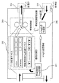
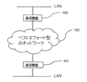
図2にネットワーク構成図を示す。図2における通信機器101の出力インターフェースの帯域をPing(Pingに限らず、他の制御用パケットを使用してもよい)を使用して自動的に制御する動作を図1に示す。
【0021】
図1の帯域測定用Ping送信部201は、Pingパケットを優先制御部202に送り、Pingの送信情報をPing応答判定部206に伝える。送信するPingの数、パケットサイズはあらかじめ設定しておく。帯域の測定に使用するのはPingに限らず、制御用のパケットでも良い。
【0022】
優先制御部202ではCBQ(Class Base Queuing:優先度に応じて各クラスに最低保証帯域を割り当てて優先制御を行う方式)で優先制御し、パケットを帯域制御部203へ送る。帯域制御部203で設定されたシェーピングレートに帯域を絞り、パケット送信部204にパケットを送り、図2の通信機器101の送信インターフェースからパケットが送信される。図2の通信機器103が受信した帯域測定用Pingに対して応答を返す。通信機器101で受信したPingの応答は、図1のパケット受信部205を通り、Ping応答判定部206に送られる。
【0023】
Ping応答判定部206で受信したPingの応答と、帯域測定用Ping送信部201からのPingの送信情報を基にして、使用できる帯域情報を作成して、帯域制御部203に伝える。帯域制御部203は、Ping応答判定部から送られてきた帯域情報によって、自動的にシェーピングレートを変更する。帯域を測定する間隔を帯域測定用Ping送信部201に設定しておくことで、定期的に使用できる帯域を測定しシェーピングレートを変更する。
【0024】
このようにして、本発明では、Pingを使用して帯域の保証されていないベストエフォート型のネットワークの帯域を測定し、実際に使用できる帯域に合わせて、自動的にかつ定期的にネットワーク機器の送信インターフェースの帯域を制御することで、より品質の高いネットワーク通信システムを提供することができる。帯域の測定にはPingに限らず、制御用のパケットを使用してもよい。
【0025】
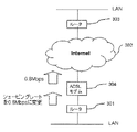
次に、本発明の実施例であるベストエフォート型のネットワークを介した通信におけるシェーピングレートの自動設定について説明する。本発明の第1の実施形態であるネットワーク構成図を図3に示す。
【0026】
図3に示すように、ルータ301はADSLモデム304、インターネット302を介して、ルータ303に接続する。ルータ301のLAN側のネットワークとルータ303のLAN側のネットワークで通信を行う。ルータ301の出力インターフェースの帯域を自動的に制御する動作について図1を用いて説明する。
【0027】
ルータ301は帯域測定用Ping送信部201、優先度に合わせてパケットを送信する優先制御部202、出力インターフェースの帯域を変更する帯域制御部203、パケットの送受信部204、205、Pingの応答を受信して、帯域情報を帯域制御部203へ送るPing応答判定部206を有する。ルータ303はインターネットに接続し、データの送受信やルータ301からのPingに応答を返す。
【0028】
以上、詳細に実施例の構成を述べたが、図3のインターネット302、ADSLモデム304は、当業者にとってよく知られており、また本発明とは直接関係しないので、その詳細な構成は省略する。
【0029】
本発明の第1の実施形態の動作について説明する。図3のネットワーク構成では、ADSLモデム304とインターネット302の間は帯域の保証されていないベストエフォート型のネットワークであり、上り方向で最大1Mbpsの帯域を有するが、実際に使用できる帯域は0.8Mbpsの場合を考える。図3に示すルータ301の出力インターフェースの帯域を自動的に制御する動作について図1を用いて説明する。
【0030】
帯域測定用Ping送信部201では、あらかじめ設定されたPingの数、パケットサイズで、Pingパケットを優先制御部202に送る。同時に、送信したPingの情報をPing応答判定部206に伝える。優先制御部202では、クラス毎に最低保証帯域を割り当ててパケットの優先制御を行う、CBQ(Class Base Queuing)の機能を有する。帯域測定用Ping送信部201から来たPingと他のパケットを異なるクラスに入れる。他の通信に与える影響を少なくするため、帯域測定用Pingが入るクラスの最低保証帯域は低めに設定する。
【0031】
帯域制御部203では、ルータ301の出力インターフェースから送信できる最大の帯域(シェーピングレート)を設定しておく。図3の場合、上りが最大1MbpsのADSLサービスのため、シェーピングレートを1Mbpsに設定している。帯域制御用Pingの送信時は帯域制御用Pingと他の通信のパケットを優先制御部202で優先制御し、帯域制御部203でシェーピングし、パケット送信部204を通り、ルータ301の出力インターフェースから送信される。
【0032】
ルータ301から送信されたパケットはADSLモデム304、インターネット302を通ってルータ303まで到達する。途中のADSL回線などは帯域が保証されていないベストエフォート型のネットワークのため、ADSLモデム304からはあらかじめルータ301の帯域制御部203に設定しているシェーピングレート(1Mbps)以下の帯域でしかパケットを送信することができない場合がある。図3では実際に使用できる回線が0.8Mbpsであった場合を示している。そのため、パケットの優先度や帯域測定用Pingに関わらず、一部のパケットがADSLモデム304で廃棄される。ルータ303は受信した帯域測定用のPingの応答をルータ301に送信する。
【0033】
図3は、帯域制御用Pingを20個送信し、ADSLモデムで4個廃棄され、16個が対向のルータ303へ到達し、ルータ303は受信した16個のPingに対して、ルータ301へ応答を返した場合を示している。
【0034】
Pingの応答パケットはルータ301のパケット受信部205を通って、Ping応答判定部206に送られる。Ping応答判定部は、送信された帯域測定用Pingと、受信したPingの応答から、使用できるネットワークの帯域情報を帯域制御部203に伝える。帯域制御部では使用できる帯域情報によってシェーピングレートを自動的に変更する。
【0035】
ルータ301の出力インターフェースの帯域(シェーピングレート)を変更した後の動作を図4に示す。ルータ301のシェーピングレートを測定した帯域に変更することで、優先制御をしてルータ301から送信されたパケットは、帯域が保証されていないベストエフォート型のネットワークで廃棄されることなく、対向のルータ303に到達する。上記方法でルータ301は定期的に帯域の測定を行い、シェーピングレートを自動的に最適な帯域に変更する。
【0036】
以上、第1の実施形態によれば、帯域が保証されていないベストエフォート型のネットワークでは、場所、時間、回線事業者、プロバイダなどによって、使用できる帯域が変化するが、使用できる回線の帯域を定期的に測定し、ネットワーク機器の帯域を自動的に変更することで、より品質の高いネットワーク通信装置、方法、およびシステムを提供することが可能になる。
【0037】
次に、本発明の実施例であるインターネットとの通信を行う場合のシェーピングレートの自動設定について説明する。本発明の第2の実施形態であるネットワーク構成図を図5に示す。
【0038】
図5に示すように、ルータ401は、プロバイダ403内の通信機器(BAS等)402を介して、インターネット405に接続する。ルータ401の出力インターフェースの帯域を自動的に制御する動作は、前実施例と同じのため省略する。
【0039】
プロバイダ403内の通信機器(BAS等)402は、ルータ401のLAN側のネットワークとインターネット405の通信を中継する。インターネット405内の通信機器404は誰でもアクセスできる機器とする。通信機器(BAS等)402と通信機器404はルータ401からのPingに応答を返す。
【0040】
次に、本発明の実施例の動作について説明する。図5のネットワーク構成において、ルータ401とインターネット405の間は帯域の保証されていないベストエフォート型のネットワークである。図5に示すように、ルータ401の出力インターフェースの帯域を自動的に制御する動作は第1の実施例と同じである。
【0041】
図5のルータ401から送信される帯域測定用Pingの送信先を、プロバイダ403内の通信機器(BAS等)402やインターネット405内の通信機器404にすることで、インターネット405と通信をする場合でも、ルータ401の出力インターフェースの帯域を自動的に変更することができる。
【0042】
以上、本発明の第2の実施形態によれば、インターネットは帯域が保証されていないベストエフォート型のネットワークであり、プロバイダまでの回線や、プロバイダからインターネットまでの回線などで廃棄したくないパケットが廃棄されることがある。プロバイダやインターネット内の通信機器までの使用できる回線の帯域を定期的に測定し、拠点内の通信機器の出力インターフェースの帯域を自動的に変更することで、より品質の高い通信行うことが可能になる。
【0043】
次に、本発明の実施例であるPing以外の制御用パケットを使用して帯域を測定する方式を用いたシェーピングレートの自動設定について説明する。本発明の第3の実施形態であるネットワーク構成図を図6に示す。
【0044】
図6に示すように、通信機器501、503は、帯域の保証されていないベストエフォート型のネットワーク502に接続する。通信機器501の出力インターフェースの帯域を自動的に制御する動作は前項までの実施例と同じであるが、図1の帯域測定用Ping送信部からは、Pingの代わりの制御用パケットを送信する。また、図1のPing応答判定部206は必要ない。
【0045】
本発明の実施例の動作について説明する。帯域を測定するためにPing以外の制御用パケットを使用する場合、図1の帯域測定用Ping送信部からは、Pingの代わりの制御用パケットを送信する。制御用パケットには制御用パケットの送信する個数とパケットサイズなどの情報が含まれている。制御用パケットには再送制御が発生しないUDPのパケットを使用する。
【0046】
対向の通信機器503の制御パケットに応答する構造について、図7を用いて説明する。通信機器503は制御パケット受信部601と帯域情報送信部602を有する。通信機器503が受信した制御パケットは、制御パケット受信部で受信され、受信パケット数や制御パケットに含まれる情報が帯域情報送信部602に送られる。帯域情報送信部602は、受信した制御パケットから計算した帯域の情報を通信機器501へ送信する。
【0047】
通信機器503から送信された帯域情報は通信機器501のパケット受信部205で受信し、直接帯域制御部203に送られる。帯域制御部203は受信した帯域情報を用いて自動的にシェーピングレートを変更する。
【0048】
以上、本発明の第3の実施形態によれば、帯域が保証されていないベストエフォート型のネットワークでは、場所、時間、回線事業者、プロバイダなどによって、使用できる帯域が変化する。使用できる回線の帯域を定期的に測定し、ネットワーク機器の帯域を自動的に変更することで、より品質の高いネットワーク通信システムを提供することが可能になる。制御用パケットを用いて帯域を測定することで、応答のパケットを1つにし、ネットワークや通信機器に与える負荷を軽減することができる。
【0049】
【発明の効果】
請求項1記載のシェーピングレート設定装置によれば、ベストエフォート型ネットワーク上の通信機器と接続されるシェーピングレート設定装置であって、帯域を測定するPingと、Pingの送信情報とを同時に送信するPing送信部と、Ping送信部から受信したPingを優先度に応じて送信する優先制御部と、Ping送信部からPingの送信情報を受信するPing応答判定部と、シェーピングレートを設定し、優先制御部から受信したPingをシェーピングし、送信する帯域制御部と、帯域制御部からPingを受信し、通信機器に送信するパケット送信部と、通信機器から応答Pingを受信し、Ping応答判定部に送信するパケット受信部とを有し、Ping応答判定部は、受信した応答Pingと、Ping送信部から受信したPingの送信情報とを基にして、実際に使用できる帯域を示す帯域情報を作成し、帯域制御部に伝え、帯域制御部は、Ping応答判定部から受信した帯域情報によって、シェーピングレートを変更することを特徴とするので、より品質の高い通信行うことが可能になる。
【0050】
請求項2記載のシェーピングレート設定装置によれば、請求項1記載のシェーピングレート設定装置において、Ping送信部は、送信するPingの数およびパケットサイズを予め設定することを特徴とするので、より品質の高い通信行うことが可能になる。
【0051】
請求項3記載のシェーピングレート設定装置によれば、請求項1記載のシェーピングレート設定装置において、Ping送信部は、Pingに代えて、制御用パケットを送信することを特徴とするので、ネットワークや通信機器に与える負荷を軽減することができ、また、より品質の高い通信行うことが可能になる。
【0052】
請求項4記載のシェーピングレート設定装置によれば、請求項1記載のシェーピングレート設定装置において、Pingは、プロバイダ内の通信機器の帯域を測定することを特徴とするので、より品質の高い通信行うことが可能になる。
【0053】
請求項5記載のシェーピングレート設定装置によれば、請求項1記載のシェーピングレート設定装置において、優先制御部は、各クラスに最低保証帯域を割り当てて優先制御を行うことを特徴とするので、より品質の高い通信行うことが可能になる。
【0054】
請求項6記載のシェーピングレート設定装置によれば、請求項1または5記載のシェーピングレート設定装置において、優先制御部は、送信部から受信したPingと他のパケットとを異なるクラスに入れることを特徴とするので、より品質の高い通信行うことが可能になる。
【0055】
請求項7記載のシェーピングレート設定装置によれば、請求項1または5記載のシェーピングレート設定装置において、優先制御部は、Pingが入るクラスの最低保証帯域を低めに設定することを特徴とするので、他の通信に与える影響を少なくでき、また、より品質の高い通信行うことが可能になる。
【0056】
請求項8記載のシェーピングレート設定装置によれば、請求項1記載のシェーピングレート設定装置において、帯域制御部は、パケット送信部からPingを送信できる最大のシェーピングレートを設定することを特徴とするので、より品質の高い通信行うことが可能になる。
【0057】
請求項9記載のシェーピングレート設定装置によれば、請求項1記載のシェーピングレート設定装置において、Ping送信部は、予め帯域を測定する間隔を設定することによって、使用できる帯域を定期的に測定することを特徴とするので、より品質の高い通信行うことが可能になる。
【0058】
請求項10記載のシェーピングレート設定方法によれば、ベストエフォート型ネットワーク上の通信機器と接続されるシェーピングレート設定装置で用いられるシェーピングレート設定方法であって、帯域を測定する間隔を設定し、Pingと、 Pingの送信情報とを同時に送信し、Pingを優先度に応じて優先制御し、Pingをシェーピングし、通信機器に送信し、通信機器から応答Pingを受信し、応答Pingと、Pingの送信情報とを基にして、実際に使用できる帯域を示す帯域情報を作成し、帯域情報によって、定期的に前記シェーピングレートを変更することを特徴とするので、より品質の高い通信行うことが可能になる。
【0059】
請求項11記載のシェーピングレート設定システムによれば、ベストエフォート型ネットワークを介し、通信機器とシェーピングレート設定装置が接続されるシェーピングレート設定システムであって、シェーピングレート設定装置が通信機器に帯域測定用の制御用パケットを送信する制御用パケット送信手段と、通信機器が受信した制御用パケットを基にして、帯域情報を作成する帯域情報作成手段と、シェーピングレート設定装置が通信機器から帯域情報を取得する帯域情報取得手段と、シェーピングレート設定装置が帯域情報を用いてシェーピングレートを変更するシェーピングレート変更手段とを有することを特徴とするので、ネットワークや通信機器に与える負荷を軽減することができ、また、より品質の高い通信行うことが可能になる。
【図面の簡単な説明】
【図1】本発明の実施形態であるシェーピングレート設定装置の構成を示す図である。
【図2】本発明の実施形態であるネットワーク構成を示す図である。
【図3】本発明の第1の実施形態であるネットワーク構成を示す図である。
【図4】本発明の第1の実施形態にかかるシェーピングレート変更後の動作を示す図である。
【図5】本発明の第2の実施形態であるネットワーク構成を示す図である。
【図6】本発明の第3の実施形態であるネットワーク構成を示す図である。
【図7】本発明の第3の実施形態にかかる対向の通信装置の構成を示す図である。
【符号の説明】
101 通信機器
102 ベストエフォート型のネットワーク
103 通信機器
201 帯域測定用Ping送信部
202 優先制御部
203 帯域制御部
204 パケット送信部
205 パケット受信部
206 Ping応答判定部
301 ルータ
302 インターネット
303 ルータ
304 ADSLモデム
401 ルータ
402 通信機器
403 プロバイダ
404 通信機器
405 インターネット
501 通信機器
502 ベストエフォート型のネットワーク
503 通信機器
601 帯域測定用の制御パケット受信部
602 帯域情報送信部[0001]
TECHNICAL FIELD OF THE INVENTION
The present invention relates to a shaping rate setting device, a shaping rate setting method, and a shaping rate setting system.
[0002]
[Prior art]
In the conventional QoS technology, the communication quality of the Internet and the intranet is improved by performing priority control and band control by a network device, giving priority to a packet with a high priority, and narrowing a band of an output interface. However, in a best-effort network where the bandwidth is not guaranteed, if the bandwidth of the actually usable line falls below the set shaping rate, it may be discarded by the network regardless of the packet priority. .
[0003]
As a prior art example, there is a "data transfer method" in which, when a lower layer protocol has information on a transmittable rate from a network, an upper layer protocol uses the information to transmit a packet. reference). Further, there is an “IP packet routing device having a shaping function” capable of avoiding a failure that occurs when packets concentrate on a specific processing unit and performing smooth routing of IP packets (for example, see Patent Document 2). Also, regarding a communication device that is a node of a connectionless network and a band management method applied to the communication device, the transmission band is automatically set to a value that matches the band of all communication devices arranged on a common network. There is a “communication device and band management method” that is set dynamically (for example, see Patent Document 3).
[0004]
[Patent Document 1]
JP 2001-168871 A [Patent Document 2]
Japanese Patent Application Laid-Open No. 2002-217960 [Patent Document 3]
JP-A-2002-247092
[Problems to be solved by the invention]
However, according to the inventions described in Patent Documents 1 to 3, in a best-effort network in which the bandwidth is not guaranteed, the available bandwidth varies depending on the location, time, line carrier, provider, and the like, so that communication quality is ensured. There was a problem in the point.
[0006]
The present invention has been made in view of the above circumstances, and has a shaping rate setting for automatically controlling the bandwidth of an output interface of a communication device in accordance with the bandwidth of a best-effort network such as the Internet, where the bandwidth is not guaranteed. It is an object to provide an apparatus, a shaping rate setting method, and a shaping rate setting system.
[0007]
[Means for Solving the Problems]
In order to solve this problem, a shaping rate setting device according to claim 1 is a shaping rate setting device connected to a communication device on a best-effort network. A Ping transmission unit that simultaneously transmits the Ping, a priority control unit that transmits the Ping received from the Ping transmission unit according to the priority, a Ping response determination unit that receives the Ping transmission information from the Ping transmission unit, and a shaping rate. The Ping received from the priority control unit is shaped and transmitted, a bandwidth control unit that receives the Ping from the bandwidth control unit, transmits a packet to the communication device, receives a Ping response from the communication device, and receives a Ping response. A ping response determination unit that transmits the received response to the packet. Based on the ing and the ping transmission information received from the ping transmission unit, band information indicating an actually usable band is created and transmitted to the band control unit, and the band control unit receives the ping from the ping response determination unit. The shaping rate is changed according to band information.
[0008]
A shaping rate setting device according to a second aspect is characterized in that, in the shaping rate setting device according to the first aspect, the ping transmission unit presets the number of pings to be transmitted and the packet size.
[0009]
According to a third aspect of the present invention, in the shaping rate setting apparatus according to the first aspect, the ping transmission unit transmits a control packet instead of the ping.
[0010]
According to a fourth aspect of the present invention, in the shaping rate setting apparatus according to the first aspect, the ping measures a band of a communication device in the provider.
[0011]
According to a fifth aspect of the present invention, there is provided a shaping rate setting device according to the first aspect, wherein the priority control unit performs priority control by allocating a minimum guaranteed bandwidth to each class.
[0012]
The shaping rate setting device according to claim 6 is the shaping rate setting device according to claim 1 or 5, wherein the priority control unit puts the ping received from the transmission unit and another packet into different classes. .
[0013]
According to a seventh aspect of the present invention, in the shaping rate setting apparatus according to the first or fifth aspect, the priority control unit sets a lower guaranteed bandwidth of a class to which Ping enters.
[0014]
The shaping rate setting device according to claim 8 is the shaping rate setting device according to claim 1, wherein the band control unit sets a maximum shaping rate at which a ping can be transmitted from the packet transmitting unit.
[0015]
In the shaping rate setting device according to the ninth aspect, in the shaping rate setting device according to the first aspect, the ping transmission unit periodically measures an available bandwidth by setting an interval for measuring the bandwidth in advance. Features.
[0016]
A shaping rate setting method according to claim 10, which is a shaping rate setting method used in a shaping rate setting device connected to a communication device on a best effort type network, wherein an interval for measuring a band is set, and Ping; Ping transmission information is transmitted simultaneously, Ping is prioritized according to priority, Ping is shaped, transmitted to the communication device, a response Ping is received from the communication device, and the response Ping and the Ping transmission information are transmitted. Based on the above, band information indicating a band that can be actually used is created, and the shaping rate is periodically changed based on the band information.
[0017]
12. The shaping rate setting system according to claim 11, wherein the shaping rate setting device is configured to connect the communication device and the shaping rate setting device via a best-effort network, wherein the shaping rate setting device controls the communication device for band measurement. Packet transmitting means for transmitting a packet for use, bandwidth information creating means for creating bandwidth information based on the control packet received by the communication device, and a bandwidth for the shaping rate setting device to acquire the bandwidth information from the communication device. The information acquisition means and the shaping rate setting device include a shaping rate changing means for changing the shaping rate using the band information.
[0018]
BEST MODE FOR CARRYING OUT THE INVENTION
Hereinafter, embodiments of the present invention will be described in detail with reference to the accompanying drawings.
[0019]
The present invention is characterized in that the bandwidth of an output interface of a communication device is automatically controlled in accordance with the bandwidth of a best-effort network such as the Internet, whose bandwidth is not guaranteed.
[0020]
FIG. 2 shows a network configuration diagram. FIG. 1 shows an operation of automatically controlling the band of the output interface of the communication device 101 in FIG. 2 using Ping (other control packets may be used instead of Ping).
[0021]
1 transmits a Ping packet to the
[0022]
The
[0023]
Based on the Ping response received by the Ping
[0024]
In this way, according to the present invention, the bandwidth of the best-effort network whose bandwidth is not guaranteed is measured using Ping, and the network equipment is automatically and periodically adjusted according to the actually usable bandwidth. By controlling the band of the transmission interface, a higher quality network communication system can be provided. The measurement of the bandwidth is not limited to Ping, and a control packet may be used.
[0025]
Next, automatic setting of a shaping rate in communication through a best-effort network according to an embodiment of the present invention will be described. FIG. 3 shows a network configuration diagram according to the first embodiment of the present invention.
[0026]
As shown in FIG. 3, the
[0027]
The
[0028]
The configuration of the embodiment has been described in detail above. However, since the
[0029]
The operation of the first embodiment of the present invention will be described. In the network configuration of FIG. 3, a bandwidth between the
[0030]
The band measurement
[0031]
The
[0032]
The packet transmitted from the
[0033]
FIG. 3 shows that 20 band control pings are transmitted, 4 are discarded by the ADSL modem, 16 arrive at the
[0034]
The Ping response packet is sent to the Ping
[0035]
FIG. 4 shows the operation after the bandwidth (shaping rate) of the output interface of the
[0036]
As described above, according to the first embodiment, in the best-effort network in which the bandwidth is not guaranteed, the available bandwidth varies depending on the location, time, line carrier, provider, and the like. By periodically measuring and automatically changing the bandwidth of the network device, it becomes possible to provide a higher quality network communication device, method and system.
[0037]
Next, the automatic setting of the shaping rate when performing communication with the Internet according to the embodiment of the present invention will be described. FIG. 5 shows a network configuration diagram according to the second embodiment of the present invention.
[0038]
As shown in FIG. 5, the
[0039]
A communication device (BAS or the like) 402 in the
[0040]
Next, the operation of the embodiment of the present invention will be described. In the network configuration shown in FIG. 5, a network between the
[0041]
By setting the transmission destination of the bandwidth measurement ping transmitted from the
[0042]
As described above, according to the second embodiment of the present invention, the Internet is a best-effort network in which the bandwidth is not guaranteed, and a packet that the user does not want to discard on a line to the provider or a line from the provider to the Internet. May be discarded. Higher quality communication can be achieved by periodically measuring the bandwidth of the line that can be used up to the provider and the communication equipment in the Internet and automatically changing the bandwidth of the output interface of the communication equipment in the base Become.
[0043]
Next, automatic setting of a shaping rate using a method of measuring a band by using a control packet other than Ping according to an embodiment of the present invention will be described. FIG. 6 shows a network configuration diagram according to the third embodiment of the present invention.
[0044]
As shown in FIG. 6, the
[0045]
The operation of the embodiment of the present invention will be described. When a control packet other than Ping is used to measure a band, a control packet in place of Ping is transmitted from the band measurement Ping transmission unit in FIG. The control packet includes information such as the number of control packets to be transmitted and the packet size. A UDP packet in which retransmission control does not occur is used as the control packet.
[0046]
A structure for responding to a control packet of the
[0047]
The band information transmitted from the
[0048]
As described above, according to the third embodiment of the present invention, in a best-effort network where the bandwidth is not guaranteed, the available bandwidth changes depending on the location, time, line carrier, provider, and the like. By periodically measuring the bandwidth of the usable line and automatically changing the bandwidth of the network device, it is possible to provide a higher quality network communication system. By measuring the band using the control packet, the number of response packets can be reduced to one, and the load on the network and the communication device can be reduced.
[0049]
【The invention's effect】
According to the shaping rate setting device of the first aspect, the shaping rate setting device is connected to the communication device on the best effort type network, and the ping for measuring the bandwidth and the ping transmission information at the same time. A transmission unit, a priority control unit that transmits a ping received from the ping transmission unit according to the priority, a ping response determination unit that receives ping transmission information from the ping transmission unit, a shaping rate, and a priority control unit , A bandwidth controller that shapes and transmits the ping received from the PDU, a packet transmitter that receives the ping from the bandwidth controller, and transmits the ping to the communication device, receives a response ping from the communication device, and transmits the ping to the ping response determination unit A Ping response determination unit, which receives the response Ping and the Ping Based on the Ping transmission information received from the transmitting unit, band information indicating an actually usable band is created and transmitted to the band control unit, and the band control unit uses the band information received from the Ping response determining unit to Since the shaping rate is changed, communication with higher quality can be performed.
[0050]
According to the shaping rate setting device according to the second aspect, in the shaping rate setting device according to the first aspect, the ping transmission unit sets the number of pings to be transmitted and the packet size in advance. High communication can be performed.
[0051]
According to the shaping rate setting device of the third aspect, in the shaping rate setting device of the first aspect, the ping transmission unit transmits a control packet instead of the ping, so that the network or communication The load on the device can be reduced, and higher quality communication can be performed.
[0052]
According to the shaping rate setting device according to the fourth aspect, in the shaping rate setting device according to the first aspect, since Ping measures a band of a communication device in a provider, higher quality communication is performed. It becomes possible.
[0053]
According to the shaping rate setting device of the fifth aspect, in the shaping rate setting device of the first aspect, the priority control unit performs priority control by allocating a minimum guaranteed bandwidth to each class. High quality communication can be performed.
[0054]
According to the shaping rate setting device of the sixth aspect, in the shaping rate setting device of the first or fifth aspect, the priority control unit puts the ping received from the transmitting unit and another packet into different classes. , Communication with higher quality can be performed.
[0055]
According to the shaping rate setting device of the seventh aspect, in the shaping rate setting device of the first or fifth aspect, the priority control unit sets the minimum guaranteed bandwidth of the class in which the ping enters to a lower level. In addition, the influence on other communications can be reduced, and higher quality communications can be performed.
[0056]
According to the shaping rate setting device of the eighth aspect, in the shaping rate setting device of the first aspect, the band control unit sets a maximum shaping rate at which a ping can be transmitted from the packet transmitting unit. It is possible to perform higher quality communication.
[0057]
According to the shaping rate setting device of the ninth aspect, in the shaping rate setting device of the first aspect, the ping transmitting unit periodically measures an available bandwidth by setting an interval for measuring the bandwidth in advance. Because of this feature, higher quality communication can be performed.
[0058]
According to the shaping rate setting method of the tenth aspect, there is provided a shaping rate setting method used in a shaping rate setting device connected to a communication device on a best effort type network, wherein an interval for measuring a bandwidth is set, and a ping is set. And Ping transmission information are transmitted at the same time, the Ping is prioritized according to the priority, the Ping is shaped, transmitted to the communication device, the response Ping is received from the communication device, and the response Ping and the transmission of the Ping are transmitted. Based on the information, band information indicating a band that can be actually used is created, and the shaping rate is periodically changed according to the band information, so that higher quality communication can be performed. Become.
[0059]
According to the shaping rate setting system according to the eleventh aspect, there is provided a shaping rate setting system in which a communication device and a shaping rate setting device are connected via a best effort type network, wherein the shaping rate setting device is connected to the communication device for bandwidth measurement. A control packet transmitting unit for transmitting a control packet of the communication device, a band information generating unit for generating band information based on the control packet received by the communication device, and a shaping rate setting device acquiring the band information from the communication device Bandwidth information acquisition means, and the shaping rate setting device characterized by having a shaping rate change means to change the shaping rate using the bandwidth information, it is possible to reduce the load on the network and communication equipment, In addition, higher quality communication is possible It made.
[Brief description of the drawings]
FIG. 1 is a diagram showing a configuration of a shaping rate setting device according to an embodiment of the present invention.
FIG. 2 is a diagram illustrating a network configuration according to an embodiment of the present invention.
FIG. 3 is a diagram showing a network configuration according to the first embodiment of the present invention.
FIG. 4 is a diagram illustrating an operation after a shaping rate is changed according to the first embodiment of the present invention.
FIG. 5 is a diagram illustrating a network configuration according to a second embodiment of the present invention.
FIG. 6 is a diagram illustrating a network configuration according to a third embodiment of the present invention.
FIG. 7 is a diagram illustrating a configuration of an opposing communication device according to a third embodiment of the present invention.
[Explanation of symbols]
Claims (11)
帯域を測定するPingと、前記Pingの送信情報とを同時に送信するPing送信部と、
前記Ping送信部から受信した前記Pingを優先度に応じて送信する優先制御部と、
前記Ping送信部から前記Pingの送信情報を受信するPing応答判定部と、
シェーピングレートを設定し、前記優先制御部から受信した前記Pingをシェーピングし、送信する帯域制御部と、
前記帯域制御部から前記Pingを受信し、前記通信機器に送信するパケット送信部と、
前記通信機器から応答Pingを受信し、前記Ping応答判定部に送信するパケット受信部とを有し、
前記Ping応答判定部は、受信した前記応答Pingと、前記Ping送信部から受信した前記Pingの送信情報とを基にして、実際に使用できる帯域を示す帯域情報を作成し、前記帯域制御部に伝え、
前記帯域制御部は、前記Ping応答判定部から受信した前記帯域情報によって、前記シェーピングレートを変更することを特徴とするシェーピングレート設定装置。A shaping rate setting device connected to a communication device on a best-effort network,
Ping for measuring a band, and a Ping transmitting unit for simultaneously transmitting the transmission information of the Ping,
A priority control unit that transmits the Ping received from the Ping transmission unit according to a priority;
A Ping response determination unit that receives the Ping transmission information from the Ping transmission unit;
Setting a shaping rate, shaping the Ping received from the priority control unit, and transmitting a band control unit;
A packet transmitting unit that receives the Ping from the band control unit and transmits the Ping to the communication device;
A packet receiving unit that receives a response Ping from the communication device and transmits the response Ping to the Ping response determination unit;
The Ping response determination unit, based on the received response Ping and the transmission information of the Ping received from the Ping transmission unit, creates band information indicating a band that can be actually used, the band control unit Tell
The shaping rate setting device, wherein the bandwidth control unit changes the shaping rate according to the bandwidth information received from the Ping response determination unit.
帯域を測定する間隔を設定し、Pingと、前記Pingの送信情報とを同時に送信し、
前記Pingを優先度に応じて優先制御し、
前記Pingをシェーピングし、前記通信機器に送信し、
前記通信機器から応答Pingを受信し、
前記応答Pingと、前記Pingの送信情報とを基にして、実際に使用できる帯域を示す帯域情報を作成し、
前記帯域情報によって、定期的に前記シェーピングレートを変更することを特徴とするシェーピングレート設定方法。A shaping rate setting method used in a shaping rate setting device connected to a communication device on a best effort type network,
Set the interval to measure the band, transmit Ping and the transmission information of the Ping simultaneously,
Priority control of the Ping according to priority,
Shape the Ping and send it to the communication device,
Receiving a response Ping from the communication device;
Based on the response Ping and the transmission information of the Ping, create bandwidth information indicating an actually usable bandwidth,
A shaping rate setting method, wherein the shaping rate is periodically changed according to the band information.
前記シェーピングレート設定装置が前記通信機器に帯域測定用の制御用パケットを送信する制御用パケット送信手段と、
前記通信機器が受信した前記制御用パケットを基にして、前記帯域情報を作成する帯域情報作成手段と、
前記シェーピングレート設定装置が前記通信機器から前記帯域情報を取得する帯域情報取得手段と、
前記シェーピングレート設定装置が前記帯域情報を用いてシェーピングレートを変更するシェーピングレート変更手段と、
を有することを特徴とするシェーピングレート設定システム。A shaping rate setting system in which a communication device and a shaping rate setting device are connected via a best effort type network,
A control packet transmitting unit in which the shaping rate setting device transmits a control packet for band measurement to the communication device,
Based on the control packet received by the communication device, band information creating means for creating the band information,
Band information obtaining means for the shaping rate setting device to obtain the band information from the communication device,
The shaping rate setting device, wherein the shaping rate setting device changes the shaping rate using the band information,
A shaping rate setting system comprising:
Priority Applications (3)
| Application Number | Priority Date | Filing Date | Title |
|---|---|---|---|
| JP2003134768A JP2004343227A (en) | 2003-05-13 | 2003-05-13 | Shaping rate setting apparatus, shaping rate setting method, and shaping rate setting system |
| US10/845,938 US20040228289A1 (en) | 2003-05-13 | 2004-05-13 | Apparatus for determining shaping rate and method of doing the same |
| CA 2467224 CA2467224C (en) | 2003-05-13 | 2004-05-13 | Apparatus for determining shaping rate and method of doing the same |
Applications Claiming Priority (1)
| Application Number | Priority Date | Filing Date | Title |
|---|---|---|---|
| JP2003134768A JP2004343227A (en) | 2003-05-13 | 2003-05-13 | Shaping rate setting apparatus, shaping rate setting method, and shaping rate setting system |
Publications (1)
| Publication Number | Publication Date |
|---|---|
| JP2004343227A true JP2004343227A (en) | 2004-12-02 |
Family
ID=33410684
Family Applications (1)
| Application Number | Title | Priority Date | Filing Date |
|---|---|---|---|
| JP2003134768A Pending JP2004343227A (en) | 2003-05-13 | 2003-05-13 | Shaping rate setting apparatus, shaping rate setting method, and shaping rate setting system |
Country Status (3)
| Country | Link |
|---|---|
| US (1) | US20040228289A1 (en) |
| JP (1) | JP2004343227A (en) |
| CA (1) | CA2467224C (en) |
Cited By (4)
| Publication number | Priority date | Publication date | Assignee | Title |
|---|---|---|---|---|
| JP2008085692A (en) * | 2006-09-28 | 2008-04-10 | Fujitsu Ltd | Best-effort band assigning method and device |
| JP2009544174A (en) * | 2006-02-11 | 2009-12-10 | サムスン エレクトロニクス カンパニー リミテッド | Method for accurately and safely measuring propagation delay and distance between transmitting and receiving nodes in a packet network in a cut-through manner, and packet network node for performing this method |
| JP2012186668A (en) * | 2011-03-07 | 2012-09-27 | Mitsubishi Electric Building Techno Service Co Ltd | Building facility management system using internet |
| US8842573B2 (en) | 2009-06-25 | 2014-09-23 | Yamaha Corporation | Communication device |
Families Citing this family (3)
| Publication number | Priority date | Publication date | Assignee | Title |
|---|---|---|---|---|
| JP2007259113A (en) * | 2006-03-23 | 2007-10-04 | Nec Corp | Equipment, method and program for measuring band |
| JP5012553B2 (en) * | 2008-02-15 | 2012-08-29 | 富士通株式会社 | Frame relay apparatus, route learning program, and route learning method |
| EP2723021A1 (en) * | 2012-10-18 | 2014-04-23 | Telefonaktiebolaget L M Ericsson AB (Publ) | A method and an apparatus for determining the presence of a rate limiting mechanism in a network |
Family Cites Families (5)
| Publication number | Priority date | Publication date | Assignee | Title |
|---|---|---|---|---|
| US5710885A (en) * | 1995-11-28 | 1998-01-20 | Ncr Corporation | Network management system with improved node discovery and monitoring |
| US6711137B1 (en) * | 1999-03-12 | 2004-03-23 | International Business Machines Corporation | System and method for analyzing and tuning a communications network |
| US20050018611A1 (en) * | 1999-12-01 | 2005-01-27 | International Business Machines Corporation | System and method for monitoring performance, analyzing capacity and utilization, and planning capacity for networks and intelligent, network connected processes |
| US7032020B2 (en) * | 2001-03-30 | 2006-04-18 | Intel Corporation | System and method for determining segment and link bandwidth capacities |
| US7245584B2 (en) * | 2002-11-18 | 2007-07-17 | Avaya Technology Corp. | Method and apparatus for auditing service level agreements by test packet insertion |
-
2003
- 2003-05-13 JP JP2003134768A patent/JP2004343227A/en active Pending
-
2004
- 2004-05-13 CA CA 2467224 patent/CA2467224C/en not_active Expired - Fee Related
- 2004-05-13 US US10/845,938 patent/US20040228289A1/en not_active Abandoned
Cited By (5)
| Publication number | Priority date | Publication date | Assignee | Title |
|---|---|---|---|---|
| JP2009544174A (en) * | 2006-02-11 | 2009-12-10 | サムスン エレクトロニクス カンパニー リミテッド | Method for accurately and safely measuring propagation delay and distance between transmitting and receiving nodes in a packet network in a cut-through manner, and packet network node for performing this method |
| JP2008085692A (en) * | 2006-09-28 | 2008-04-10 | Fujitsu Ltd | Best-effort band assigning method and device |
| JP4705542B2 (en) * | 2006-09-28 | 2011-06-22 | 富士通株式会社 | Best effort bandwidth allocation method and apparatus |
| US8842573B2 (en) | 2009-06-25 | 2014-09-23 | Yamaha Corporation | Communication device |
| JP2012186668A (en) * | 2011-03-07 | 2012-09-27 | Mitsubishi Electric Building Techno Service Co Ltd | Building facility management system using internet |
Also Published As
| Publication number | Publication date |
|---|---|
| CA2467224A1 (en) | 2004-11-13 |
| US20040228289A1 (en) | 2004-11-18 |
| CA2467224C (en) | 2009-10-06 |
Similar Documents
| Publication | Publication Date | Title |
|---|---|---|
| JP4030968B2 (en) | Identifying packet data flows for multiplexing | |
| CN105939539B (en) | System and method for the dynamic bandwidth adjustment of cellular interface in network environment | |
| US7286474B2 (en) | Method and apparatus for performing admission control in a communication network | |
| JP4430597B2 (en) | NETWORK SYSTEM, TRANSMITTER DISTRIBUTION DEVICE, PACKET COMMUNICATION METHOD, AND PACKET COMMUNICATION PROGRAM | |
| WO2003103329A1 (en) | Wireless communication device and usage band determination method | |
| Fracchia et al. | WiSE: Best-path selection in wireless multihoming environments | |
| EP1854308A2 (en) | Method and apparatus for supporting data flow control in a wireless mesh network | |
| JP2004320159A (en) | Communication system and communication method | |
| US8824304B2 (en) | Reducing overhead on voice traffic | |
| EP1540981A1 (en) | Traffic control in cellular networks | |
| JP2008507204A (en) | How to manage inter-zone bandwidth in a two-way messaging network | |
| JP4347268B2 (en) | Router control device, router, IP-VPN system, and router control method | |
| EP2375797B1 (en) | ADSL and 3G Traffic Aggregation in Home Gateway Environment | |
| EP2715978B1 (en) | A system and method for reducing the data packet loss employing adaptive transmit queue length | |
| Nishiyama et al. | Wireless loss-tolerant congestion control protocol based on dynamic aimd theory | |
| JP2004343227A (en) | Shaping rate setting apparatus, shaping rate setting method, and shaping rate setting system | |
| CN109039791B (en) | Bandwidth management method and device and computer equipment | |
| EP1341350B1 (en) | A method for congestion detection for IP flows over a wireless network | |
| KR101263443B1 (en) | Schedule apparatus and method for real time service of QoS in CPE by WiBro | |
| Pu et al. | Enhancements on router-assisted congestion control for wireless networks | |
| JP4893216B2 (en) | Network management device, bandwidth control method, and program | |
| JP4108515B2 (en) | Wireless terminal device | |
| JP2004166080A (en) | Packet shaper and packet relaying device | |
| JP2003218923A (en) | Packet transmission apparatus and packet transmission processing method | |
| ShanShan et al. | Extending SWAN to provide QoS for MANETs connected to the internet |
Legal Events
| Date | Code | Title | Description |
|---|---|---|---|
| A621 | Written request for application examination |
Free format text: JAPANESE INTERMEDIATE CODE: A621 Effective date: 20060414 |
|
| A711 | Notification of change in applicant |
Free format text: JAPANESE INTERMEDIATE CODE: A712 Effective date: 20070309 |
|
| A977 | Report on retrieval |
Free format text: JAPANESE INTERMEDIATE CODE: A971007 Effective date: 20080118 |
|
| A131 | Notification of reasons for refusal |
Free format text: JAPANESE INTERMEDIATE CODE: A131 Effective date: 20080527 |
|
| A02 | Decision of refusal |
Free format text: JAPANESE INTERMEDIATE CODE: A02 Effective date: 20081007 |