JP2004340171A - Shift controller for vehicular automatic transmission - Google Patents
Shift controller for vehicular automatic transmission Download PDFInfo
- Publication number
- JP2004340171A JP2004340171A JP2003134286A JP2003134286A JP2004340171A JP 2004340171 A JP2004340171 A JP 2004340171A JP 2003134286 A JP2003134286 A JP 2003134286A JP 2003134286 A JP2003134286 A JP 2003134286A JP 2004340171 A JP2004340171 A JP 2004340171A
- Authority
- JP
- Japan
- Prior art keywords
- clutch
- transmission
- automatic transmission
- input
- predetermined
- Prior art date
- Legal status (The legal status is an assumption and is not a legal conclusion. Google has not performed a legal analysis and makes no representation as to the accuracy of the status listed.)
- Granted
Links
Images


Landscapes
- Hydraulic Clutches, Magnetic Clutches, Fluid Clutches, And Fluid Joints (AREA)
- Control Of Transmission Device (AREA)
Abstract
Description
【0001】
【発明の属する技術分野】
本発明は、車両用自動変速機の変速制御装置に関し、特に、コーストダウン変速時のドライバビリティを向上させる技術に関する。
【0002】
【従来の技術】
車両の走行状態に応じて変速段が自動的に選択される自動変速機(オートマチックトランスミッション)を備えた車両において、アクセルペダルが非操作とされているような減速惰行中のダウン変速である所謂コーストダウン変速では、エンジンブレーキ力による変速ショックが発生する可能性がある。そこで、斯かる変速ショックの発生を防止する技術が提案されている。例えば、特許文献1に記載された車両の走行制御装置がそれである。この車両の走行制御装置は、コーストダウン変速と同期して駆動力源の出力を増加させることによりエンジンブレーキ力を減殺させ、変速ショックを緩和して走行感を向上させようとするものである。
【0003】
【特許文献1】
特開昭63−284039号公報
【特許文献2】
特開平10−213216号公報
【特許文献3】
特開平10−89455号公報
【特許文献4】
特開平9−273625号公報
【特許文献5】
特開平5−99318号公報
【0004】
【発明が解決しようとする課題】
しかし、前記従来の技術では、コーストダウン変速が終了してしまうと駆動力源の出力増加制御もまた終了してしまうため、その変速後の低速側ギヤ段に付随するエンジンブレーキ力により変速ショックが発生する可能性が依然として残されていた。とりわけ、急減速時等のように変速中と変速後の加速度差が比較的大きい場合、運転者がその加速度の急変化を感じることでドライバビリティが悪化するおそれがあった。
【0005】
本発明は、以上の事情を背景として為されたものであり、その目的とするところは、コーストダウン変速時のドライバビリティを向上させる車両用自動変速機の変速制御装置を提供することにある。
【0006】
【課題を解決するための手段】
斯かる目的を達成するために、本発明の要旨とするところは、アクセルオフでの走行中における高速側ギヤ段又は変速比から低速側ギヤ段又は変速比へのコーストダウン変速に同期して駆動力源により発生させられる駆動トルクの制御を実行する車両用自動変速機の変速制御装置であって、前記コーストダウン変速に際して前記自動変速機に備えられた入力クラッチの伝達トルクを所定値まで低下させるクラッチ伝達トルク制御手段を含むことを特徴とするものである。
【0007】
【発明の効果】
このようにすれば、前記コーストダウン変速に際して前記自動変速機に備えられた入力クラッチの伝達トルクを所定値まで低下させるクラッチ伝達トルク制御手段を含むものであることから、前記コーストダウン変速に同期して実行される駆動トルク増加制御の中止時に前記自動変速機に過大なトルクが入力されることなく、変速ショックを確実に防止できる。すなわち、コーストダウン変速時のドライバビリティを向上させる車両用自動変速機の変速制御装置を提供することができる。
【0008】
【発明の他の態様】
ここで、好適には、前記自動変速機の入力回転速度が前記低速側ギヤ段又は変速比の同期回転速度付近まで変化したか否かを判定する同期判定手段を含み、前記クラッチ伝達トルク制御手段は、前記同期判定手段により前記自動変速機の入力回転速度が前記低速側ギヤ段又は変速比の同期回転速度付近まで変化したと判定される場合には、前記入力クラッチの伝達トルクを所定値まで低下させるものである。このようにすれば、前記コーストダウン変速に際しての変速ショックを好適な態様で防止できるという利点がある。
【0009】
また、好適には、前記クラッチ伝達トルク制御手段は、前記同期判定手段により前記自動変速機の入力回転速度が前記低速側ギヤ段又は変速比の同期回転速度付近まで変化したと判定される場合には、前記入力クラッチの伝達トルクを零とするものである。このようにすれば、前記コーストダウン変速に同期して実行される駆動トルク増加制御の中止時に一旦擬似ニュートラル状態を成立させることで、変速ショックを更に確実に防止できるという利点がある。
【0010】
また、好適には、車両停車時に所定の条件が成立した場合には、所定の目標値が達成されるように前記入力クラッチを所定のスリップ状態とするニュートラル制御手段を含み、前記クラッチ伝達トルク制御手段は、前記同期判定手段により前記自動変速機の入力回転速度が前記低速側ギヤ段又は変速比の同期回転速度付近まで変化したと判定される場合には、前記ニュートラル制御手段により所定の目標値を達成させるための学習値に基づいて前記入力クラッチの伝達トルクを制御するものである。このようにすれば、前記コーストダウン変速時にアクセル操作が実行された場合の変速ショックを好適に防止できるという利点がある。
【0011】
また、好適には、前記クラッチ伝達トルク制御手段は、前記入力クラッチの係合圧が所定の閾値未満である場合には、所定の第1スイープ量を加算することにより前記入力クラッチの係合圧を漸増させる第1スイープ加算手段と、前記入力クラッチの係合圧が前記閾値以上である場合には、所定の第2スイープ量を加算することにより前記入力クラッチの係合圧を漸増させる第2スイープ加算手段とを、含むものである。このようにすれば、前記コーストダウン変速時にアクセル操作が実行された場合のショックを更に好適に防止できるという利点がある。
【0012】
また、好適には、前記クラッチ伝達トルク制御手段は、前記アクセルの操作量が所定値以上となった場合には、前記入力クラッチの伝達トルクを最大値とするものである。このようにすれば、前記コーストダウン変速時のショックを防止しつつも、アクセル操作が実行された際には速やかな加速を実現できるという利点がある。
【0013】
【実施例】
以下、本発明の好適な実施例を図面に基づいて詳細に説明する。
【0014】
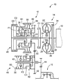
図1は、本発明が適用された車両用駆動力伝達装置10の骨子図である。この駆動力伝達装置10において、駆動力源であるエンジン12により発生させられた駆動力は、流体式伝動装置であるトルクコンバータ14、FF駆動用の自動変速機16、差動歯車装置18を経て図示しない駆動輪(前輪)へ伝達されるようになっている。上記エンジン12は、気筒内噴射される燃料の燃焼によって駆動力を発生させるガソリンエンジン等の内燃機関である。また、上記トルクコンバータ14は、上記エンジン12のクランク軸20と連結されているポンプ翼車22と、上記自動変速機16の入力軸24に連結されたタービン翼車26と、一方向クラッチ28を介して非回転部材であるハウジング30に固定されたステータ翼車32と、図示しないダンパを介して上記入力軸24に連結されたロックアップクラッチ34とを備えている。
【0015】
上記自動変速機16は、上記入力軸24上に同軸に配設されるとともにキャリアとリングギヤとがそれぞれ相互に連結されることにより所謂CR−CR結合の遊星歯車機構を構成するシングルピニオン型の一対の第1遊星歯車装置36及び第2遊星歯車装置38と、上記入力軸24と平行なカウンタ軸40上に同軸に配置された1組の第3遊星歯車装置42と、そのカウンタ軸40の軸端に固定されて上記差動歯車装置18と噛み合う出力ギヤ44とを備えている。上記第1遊星歯車装置36、第2遊星歯車装置38、及び第3遊星歯車装置42の各構成要素であるサンギヤ、リングギヤ、及びそれらに噛み合う遊星ギヤを回転可能に支持するキャリアは、4つのクラッチC0、C1、C2、及びC3によって互いに選択的に連結され、或いは3つのブレーキB1、B2、及びB3によって非回転部材であるハウジング30に選択的に連結されるようになっている。また、2つの一方向クラッチF1及びF2によって相互間の或いは上記ハウジング30との間の所定方向の相対回転が阻止されるようになっている。なお、上記差動歯車装置18は軸線(車軸)に対して対称的に構成されているため、下側を省略して示してある。
【0016】
前記入力軸24上に配設された一対の第1遊星歯車装置36、第2遊星歯車装置38、クラッチC0、C1、C2、ブレーキB1、B2、及び一方向クラッチF1により前進4段且つ後進1段の主変速部46が構成され、上記カウンタ軸40上に配設された1組の遊星歯車装置42、クラッチC3、ブレーキB3、及び一方向クラッチF2によって副変速部(アンダードライブ部)48が構成されている。上記主変速部46では、前記入力軸24は、クラッチC0を介して上記第2遊星歯車装置38のキャリアK2に、クラッチC1を介して上記第1遊星歯車装置36のサンギヤS1に、クラッチC2を介して上記第2遊星歯車装置38のサンギヤS2にそれぞれ連結されている。上記第1遊星歯車装置36のリングギヤR1と第2遊星歯車装置38のキャリアK2との間、第1遊星歯車装置36のキャリアK1と第2遊星歯車装置38のリングギヤR2との間はそれぞれ連結されており、第2遊星歯車装置38のサンギヤS2はブレーキB1を介して、第1遊星歯車装置36のリングギヤR1はブレーキB2を介して非回転部材であるハウジング30に連結されている。また、上記第2遊星歯車装置38のキャリアK2と非回転部材であるハウジング30との間には、所定方向の相対回転を阻止するための一方向クラッチF1が設けられている。そして、上記第1遊星歯車装置36のキャリアK1に固定された第1カウンタギヤ50と第3遊星歯車装置42のリングギヤR3に固定された第2カウンタギヤ52とは相互に噛み合わされている。上記副変速部48では、上記第3遊星歯車装置42のキャリアK3とサンギヤS3とがクラッチC3を介して相互に連結され、そのサンギヤS3と非回転部材であるハウジング30との間には、ブレーキB3と一方向クラッチF2とが並列に設けられている。
【0017】
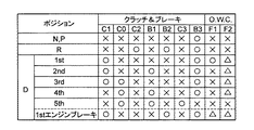
図2は、前記自動変速機16の各変速段を成立させるためのクラッチ及びブレーキの係合作動を説明する係合表である。前記クラッチC0、C1、C2、C3及びブレーキB1、B2、B3は、何れも油圧アクチュエータによって係合制御される多板式のクラッチやバンドブレーキ等の油圧式摩擦係合装置であり、前記自動変速機16では、図2に示すように、前記クラッチC0、C1、C2、C3及びブレーキB1、B2、B3が選択的に係合させられることにより、前進5段・後退1段のうちの何れかの変速段が成立させられる。この図2における「○」は係合を、「△」は駆動時のみにおける係合を、「×」は解放を意味している。例えば、第4速ギヤ段と第5速ギヤ段との間の4→5変速或いは5→4変速は、前記クラッチC3の係合或いは解放で達成され、第1速ギヤ段と第2速ギヤ段との間の1→2変速或いは2→1変速は、前記ブレーキB1の係合或いは解放で達成される。また、第2速ギヤ段と第3速ギヤ段との間の2→3変速或いは3→2変速は、前記ブレーキB1の解放及びクラッチC0の係合或いは前記ブレーキB1の係合及びクラッチC0の解放というように、前記クラッチC0及びブレーキB1のうち何れか一方が解放されると同時に他方が係合させられることにより達成される所謂クラッチツウクラッチ変速であり、第3速ギヤ段と第4速ギヤ段との間の3→4変速或いは4→3変速もまた、前記クラッチC1の解放及びブレーキB1の係合或いは前記クラッチC1の係合及びブレーキB1の解放により達成される所謂クラッチツウクラッチ変速である。
【0018】
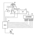
図3は、前記駆動力伝達装置10を制御するために車両に設けられた電気系統を説明するブロック線図である。この図3に示すように、前記エンジン12の吸気配管には、スロットルアクチュエータ54によって駆動操作されるスロットル弁56と、そのスロットル弁56と並列な状態で設けられてアイドル時のエンジン回転速度NE を制御するためのISC弁58とが設けられている。また、アクセルペダル60の操作量(踏込量)ACCは、アクセル操作量センサ62により検出されて電子制御装置64へ供給されるようになっており、上記スロットル弁56の開度θTHは、基本的にはそのアクセルペダル60の操作量ACCに応じて増加させられる。
【0019】
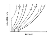
上記電子制御装置64は、CPU、RAM、ROM、及び入出力インターフェース等を備えた所謂マイクロコンピュータであって、そのCPUによりRAMの一時記憶機能を利用しつつ予めROMに記憶されたプログラムに従って入力信号を処理し、前記エンジン12の駆動制御や前記自動変速機16の変速制御等の基本的な制御を実行する。前記エンジン12の駆動制御では、例えば、燃料噴射量制御のために燃料噴射弁66を制御し、点火時期制御のためにイグナイタ68を制御し、図4に示す予め記憶された関係から実際のアクセルペダル60の操作量ACCに基づきその増加に応じて上記スロットル弁56の開度θTHが増加させられるように制御する。また、アイドルスピード制御或いはエンジン回転速度NE を所定量持ち上げるために上記ISC弁58を制御する。前記自動変速機16の変速制御では、例えば、図5に示す予め記憶された変速線図から実際のスロットル弁開度θTH及び車速Vに基づいて前記自動変速機16のギヤ段や前記ロックアップクラッチ34の変速判断を実行し、判断されたギヤ段及び係合状態が得られるように油圧制御回路70に配設された各電磁制御弁装置すなわちソレノイド弁S4、SR及びリニヤソレノイド弁SLT、SL1、SL2、SL3等の駆動を制御する。
【0020】
図6は、前記電子制御装置64の入力信号及び出力信号を説明する図である。前記駆動力伝達装置10には、前記エンジン12の回転速度を検出するエンジン回転速度センサ、車速を検出する車速センサ、前記エンジン12の吸入空気の温度を検出する吸入空気温度センサ、そのエンジン12の冷却水温度を検出するエンジン水温センサ、シフトレバーの操作位置を検出するシフトポジションセンサ、前記自動変速機16の作動油温度を検出するAT油温センサ、前記スロットル弁56の開度を検出するスロットル開度センサ、フットブレーキの作動を検出するブレーキスイッチ、前記入力軸24の回転速度に対応する前記タービン翼車26の回転速度を検出するタービン回転速度センサ、前記第2カウンタギヤ52の回転速度を検出するカウンタ回転速度センサ等が設けられており、それらのセンサ及びスイッチから、エンジン回転速度NE 、車速V、吸入空気温度TA 、エンジン水温TW 、シフトポジションPSH、AT油温TAT、スロットル開度θTH、ブレーキの作動状態BK、タービン回転速度NT 、及びカウンタ回転速度NC 等を表す信号が前記電子制御装置64へ供給されるようになっている。
【0021】
図7は、前記油圧制御回路70の要部を簡単に示す図である。この図7において、ソレノイド弁SRは、前記電子制御装置64からの指令に従ってその出力圧を比較的長い油路72を介して2−3シフト弁74に作用させてその2−3シフト弁74を1速乃至2速側と3速乃至5速側とに択一的に切り換える。ソレノイド弁S4は、前記電子制御装置64からの指令に従ってその出力圧を3速乃至5速側に切換られた上記2−3シフト弁74を介して4−5シフト弁76に作用させ、その4−5シフト弁76を1速乃至4速側と5速側とに択一的に切り換える。すなわち、上記4−5シフト弁76が1速乃至4速側に切換られているときにはライン圧PL がブレーキB3へ供給され、5速側に切換られているときにはDレンジ圧PD がクラッチC3及びアキュムレータAC3へ供給される。リニヤソレノイド弁SLTは、前記電子制御装置64からの指令に従ってその出力圧を背圧コントロール弁78に供給し、その出力圧に対応する背圧を発生させて上記アキュムレータAC3の背圧ポートへ供給させる。
【0022】
リニヤソレノイド弁SL1は、前記電子制御装置64からの指令に従ってその出力圧をB1コントロール弁80に供給し、その出力圧に対応する係合圧PB1を発生及び調圧させてブレーキB1及びそのアキュムレータAB1へ供給する。リニヤソレノイド弁SL2は、前記電子制御装置64からの指令に従ってその出力圧をソレノイド弁SRにより切り換えられる上記2−3シフト弁74を介してC0コントロール弁82へ供給し、その出力圧に対応する係合圧PC0を発生及び調圧させてクラッチC0及びそのアキュムレータAC0へ供給する。リニヤソレノイド弁SL3は、前記電子制御装置64からの指令に従ってその出力圧をC1コントロール弁84へ供給し、その出力圧に対応する係合圧PC1を発生及び調圧させてクラッチC1及びそのアキュムレータAC1へ供給する。上記クラッチC0の係合圧PC0及びクラッチC1の係合圧PC1は、その係合圧PC1によって切換られるクラッチ圧供給制御弁86を介してクラッチC0及びクラッチC1へ供給される。
【0023】
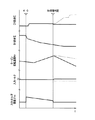
図8は、前記電子制御装置64の制御機能の要部を説明する機能ブロック線図であり、図9は、前記電子制御装置64によるコーストダウン変速制御の一例として4→3変速制御を示すタイムチャートである。なお、図9における破線は、従来の制御による変化を示している。
【0024】
変速制御手段87は、例えば、前述した図5に示す予め記憶された変速線図から実際のスロットル弁開度θTH及び車速Vに基づいて前記自動変速機16のギヤ段や前記ロックアップクラッチ34の変速判断を実行し、判断されたギヤ段及び係合状態が得られるように油圧制御回路70に配設された各電磁制御弁装置の駆動を制御する。駆動トルク制御手段88は、アクセルオフでの走行中における高速側ギヤ段又は変速比から低速側ギヤ段又は変速比へのコーストダウン変速すなわちアクセル全閉(アイドルスイッチオン)時の減速惰行状態でのダウン変速に同期して前記エンジン12により発生させられる駆動トルクを一時的に増加させる。例えば、図9に示す4→3変速では、例えば、前記ISC弁58を制御することにより、変速が開始されてから同期判定が成されるまでエンジン回転速度NE を所定量持ち上げる。
【0025】
同期判定手段90は、予め定められた関係から前記低速側ギヤ段に対応する変速比γ、車速V、及び前記自動変速機16の入力回転速度であるタービン回転速度NT に基づき、そのタービン回転速度NT が前記低速側ギヤ段の同期回転速度付近まで変化したか否かを判定する。すなわち、前記低速側ギヤ段の同期回転速度が成立する所定時間前であるか否かを判定するものであり、換言すれば、タービン回転速度NT が前記低速側ギヤ段の同期回転速度付近まで変化したか否かを予測する同期成立予測手段である。
【0026】
クラッチ伝達トルク制御手段92は、上記同期判定手段90により前記自動変速機16の入力回転速度が前記低速側ギヤ段又は変速比の同期回転速度付近まで変化したと判定される場合には、前記自動変速機16に備えられた入力クラッチの伝達トルクを所定値まで低下させ、好適には、実質的に零とする。この入力クラッチとは、コーストダウン変速に際して係合させられ、変速後の駆動力伝達に関与する摩擦係合装置であり、例えば、前述したクラッチツウクラッチ変速における係合側摩擦係合装置、すなわち、4→3変速における前記クラッチC1が該当する。なお、上記入力クラッチの伝達トルクは、その入力クラッチの係合圧により一義的に定まるものであることから、クラッチ伝達トルク制御手段92は、換言すれば、クラッチ係合圧制御手段である。例えば、図9に示す4→3変速では、前記油圧制御回路70を介して前記クラッチC1の係合圧PC1すなわちクラッチ圧が制御されることで、同期判定後すなわち駆動トルク増加制御の中止以後の伝達トルクが実質的に零とされ、一旦擬似ニュートラル状態が成立させられることにより、図9に示すように、エンジンブレーキ力に対応する負の駆動トルクが解消される。また、エンジン回転速度NE の低下に伴いタービン回転速度NT が低下させられるが、前記クラッチC1が擬似ニュートラル状態とされていることから、そのタービン回転速度NT はエンジン回転速度NE と略等しい値となる。ここで、クラッチ伝達トルク制御手段92は、好適には、前記アクセルペダル操作量ACCが所定値以上となった場合、或いは車速Vが所定速度以下となった場合には、前記入力クラッチの伝達トルクを最大値とする。
【0027】
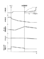
図10は、前記電子制御装置64によるコーストダウン変速制御の他の一例を示すタイムチャートである。なお、図10における破線は、従来の制御による変化を示している。
【0028】
ニュートラル制御手段94は、学習制御手段96及び学習進行判定手段98を含むものであり、例えば信号待ち等の車両停車時に所定のニュートラル制御実行条件が成立した場合には、所定の目標値が達成されるように前記入力クラッチを所定のスリップ状態とする。すなわち、エンジン回転速度NE とタービン回転速度NT との回転速度差が所定の目標値となるように前記入力クラッチのクラッチ圧を低下させることで、前記入力クラッチの伝達トルクを略零として駆動力の伝達を低減させ、燃費の向上を図ると共に可及的速やかに係合させられる状態を維持する。学習制御手段96は、可及的速やかに上記所定の目標値が達成されるように、ニュートラル制御が実行された後にそのフィードバック値を学習値として前記電子制御装置64のRAM等に記憶し、次にニュートラル制御が実行される際にはその学習値を加味したクラッチ圧を算出する。また、この学習制御の実行回数は前記電子制御装置64のRAM等に記憶される。学習進行判定手段98は、上記ニュートラル制御における学習がある程度進行しているか否かを判定する。例えば、上記学習制御が何回実行されたか、上記フィードバック制御が何秒間実行された後に上記学習制御が実行されたか等に応じてその学習制御の安定性を判定する。
【0029】
前記クラッチ伝達トルク制御手段92は、好適には、前記同期判定手段90により前記自動変速機16の入力回転速度が前記低速側ギヤ段又は変速比の同期回転速度付近まで変化したと判定される場合には、上記ニュートラル制御手段94により所定の目標値を達成させるための学習値に基づいて前記入力クラッチの伝達トルクを制御する。すなわち、上述した車両停車時における入力クラッチのニュートラル制御の学習値をコーストダウン変速時における入力クラッチの伝達トルク制御に流用する。例えば、図10に示す4→3変速では、前記油圧制御回路70を介して前記クラッチC1のクラッチ圧が上記ニュートラル制御の学習値に基づいて制御されることで、同期判定後すなわち駆動トルク増加制御の中止以後の入力クラッチが上記所定のスリップ状態とされ、伝達トルクが略零とされると共に可及的速やかに係合させられる状態が維持される。ここで、クラッチ伝達トルク制御手段92は、好適には、前記アクセルペダル操作量ACCが所定値以上となった場合、車速Vが所定速度以下となった場合、或いは予め定められた所定の制御時間が経過した場合には、前記入力クラッチの伝達トルクを最大値とする。その際、前記ニュートラル制御手段94により所定のスリップ状態とされていることで、可及的速やかに最大値が達成される。なお、上記学習進行判定手段98により上記学習がある程度進行していないと判定される場合には、前記クラッチ伝達トルク制御手段92は、上記学習値の代わりに予め設定された所定の基準値に基づいて前記入力クラッチの伝達トルクを制御する。
【0030】
また、前記クラッチ伝達トルク制御手段92は、好適には、前記入力クラッチの係合圧が所定の閾値未満である場合には、所定の第1スイープ量を加算することにより前記入力クラッチの係合圧を漸増させる第1スイープ加算手段100と、前記入力クラッチの係合圧が前記閾値以上である場合には、所定の第2スイープ量を加算することにより前記入力クラッチの係合圧を漸増させる第2スイープ加算手段102とを含むものである。この所定の閾値は、前記入力クラッチが完全係合に近い状態若しくは完全係合状態と成り得る係合圧の適合値である。また、第1スイープ量は、加速度の急変化を発生させない程度の伝達トルク上昇率となるように設定された係合圧加算量の適合値であり、第2スイープ量は、上記第1スイープ量よりも大きな値であり、前記入力クラッチの完全係合状態が成立した後に前記エンジン12の駆動トルクが上昇した場合等にその入力クラッチに滑りが生じないようにあらゆる駆動トルクに対応したクラッチ圧上昇率となるように設定された係合圧加算量の適合値である。ここで、前記入力クラッチの伝達トルクは、そのクラッチ圧により一義的に定まるものであることから、上記所定の閾値、第1スイープ量、及び第2スイープ量は、換言すれば、前記入力クラッチの伝達トルクの適合値である。例えば、図10に示す4→3変速では、同期判定後すなわち駆動トルク増加制御の中止以後に時間ta が経過するまで上記第1スイープ加算手段100により上記所定の第1スイープ量が加算されることで前記入力クラッチの係合圧が漸増させられており、その第1スイープ量の加算制御の中止以後に時間tb が経過するまで上記第2スイープ加算手段102により上記所定の第2スイープ量が加算されることで前記入力クラッチの係合圧が漸増させられている。これにより、図10に示すように、エンジンブレーキ力に対応する急激な負の駆動トルクが発生させられることなく、前記入力クラッチの伝達トルクの漸増に伴い駆動トルクが運転者に変化を感じさせない程度の変化率で減少させられる。また、前記入力クラッチのクラッチ容量がある程度存在するためタービン回転速度NT は比較的緩慢な下降を示すが、その入力クラッチの伝達トルクの漸増により完全係合状態における回転速度に漸近してゆく。
【0031】
図11は、図9のタイムチャートに対応した前記電子制御装置64による4→3コーストダウン変速制御作動の要部を説明するフローチャートであり、数msec乃至数十msec程度の極めて短いサイクルタイムで繰り返し実行されるものである。
【0032】
先ず、ステップ(以下、ステップを省略する)SA1において、アクセルオフでの走行中における高速側ギヤ段又は変速比から低速側ギヤ段又は変速比へのコーストダウン変速すなわちアクセル全閉時の減速惰行状態でのダウン変速が実行されたか否かが判断される。このSA1の判断が否定される場合には、それをもって本ルーチンが終了させられるが、SA1の判断が肯定される場合には、SA2において、前記エンジン12により発生させられる駆動トルクが増加させられ、エンジン回転速度NE が所定量持ち上げられる。次に、前記同期判定手段90に対応するSA3において、予め定められた関係から前記低速側ギヤ段に対応する変速比γ、車速V、及び前記自動変速機16の入力回転速度であるタービン回転速度NT に基づき、そのタービン回転速度NT が前記低速側ギヤ段の同期回転速度付近まで変化したか否かが判定される。このSA3の判定が否定されるうちは、肯定されるまでSA3の判定が繰り返されるが、SA3の判定が肯定される場合には、SA4において、上述したSA2にて持ち上げられたエンジン回転速度NE が通常の値に復帰させられるのと略同時に、SA5において、前記自動変速機16の入力クラッチである前記クラッチC1のクラッチ圧が所定値まで低下させられて伝達トルクが実質的に零とされる。次に、SA6において、アクセルペダル操作量ACCが所定値以上となったり、或いは車速Vが所定速度以下となる等して制御終了条件が成立したか否かが判断される。このSA6の判断が否定されるうちは、肯定されるまでSA6の判定が繰り返されるが、SA6の判定が肯定される場合には、SA7において、上述したSA5にて低下させられた前記クラッチC1の伝達トルクが通常の値に復帰させられた後、本ルーチンが終了させられる。以上の制御において、SA2及びSA4が前記駆動トルク制御手段88に、SA5乃至SA7が前記クラッチ伝達トルク制御手段92にそれぞれ対応する。
【0033】
図12は、図10のタイムチャートに対応した前記電子制御装置64による4→3コーストダウン変速制御作動の要部を説明するフローチャートであり、数msec乃至数十msec程度の極めて短いサイクルタイムで繰り返し実行されるものである。なお、この図12のフローチャートに示すSB1乃至SB4は、前述した図11のフローチャートに示すSA1乃至SA4と同様の制御であることからその説明を省略する。
【0034】
図12に示す制御では、前記学習制御進行判定手段98に対応するSB5において、前記ニュートラル制御における学習がある程度進行しているか否かが判断される。このSB5の判断が肯定される場合には、前記ニュートラル制御手段94に対応するSB6において、前記ニュートラル制御により所定の目標値を達成させるための学習値に基づいて前記クラッチC1が前記所定のスリップ状態とされて伝達トルクが略零とされた後、前記第1スイープ加算手段100に対応するSB8において、所定の第1スイープ量が加算されることにより前記クラッチC1のクラッチ圧が漸増させられるが、SB5の判断が否定される場合には、SB7において、予め設定された所定の基準値に基づいて前記クラッチC1のクラッチ圧が所定値まで低下させられて伝達トルクが実質的に零とされた後、SB8において、所定の第1スイープ量が加算されることにより前記クラッチC1のクラッチ圧が漸増させられる。次に、SB9において、前記クラッチC1のクラッチ圧が所定の閾値未満であるか否かが判断される。このSB9の判断が肯定される場合には、上述したSB8以下が再び実行されるが、SB9の判断が否定される場合には、前記第2スイープ加算手段102に対応するSB10において、所定の第2スイープ量が加算されることにより前記クラッチC1のクラッチ圧が漸増させられた後、SB11において、アクセルペダル操作量ACCが所定値以上となったり、車速Vが所定速度以下となったり、或いは予め定められた所定の制御時間が経過する等して制御終了条件が成立したか否かが判断される。このSB11の判断が否定される場合には、上述したSB10以下が再び実行されるが、SB11の判断が肯定される場合には、SB12において、前記クラッチC1のクラッチ圧が最大値すなわちMAXクラッチ圧未満であるか否かが判断される。このSB12の判断が否定される場合には、それをもって本ルーチンが終了させられるが、SB12の判断が肯定される場合には、SB13において、前記クラッチC1のクラッチ圧がMAXクラッチ圧とされた後、本ルーチンが終了させられる。以上の制御において、SB6乃至SB13が前記クラッチ伝達トルク制御手段92に対応する。
【0035】
このように、本実施例によれば、前記コーストダウン変速に際して前記自動変速機16に備えられた入力クラッチの伝達トルクを所定値まで低下させるクラッチ伝達トルク制御手段92(SA5乃至SA7、SB6乃至SB13)を含むものであることから、前記コーストダウン変速に同期して実行される駆動トルク増加制御の中止時に前記自動変速機16に過大なトルクが入力されることなく、変速ショックを確実に防止できる。すなわち、コーストダウン変速時のドライバビリティを向上させる車両用自動変速機の変速制御装置を提供することができる。
【0036】
また、前記自動変速機16の入力回転速度が前記低速側ギヤ段又は変速比の同期回転速度付近まで変化したか否かを判定する同期判定手段90(SA3、SB3)を含み、前記クラッチ伝達トルク制御手段92は、前記同期判定手段90により前記自動変速機16の入力回転速度が前記低速側ギヤ段又は変速比の同期回転速度付近まで変化したと判定される場合には、前記入力クラッチの伝達トルクを所定値まで低下させるものであるため、前記コーストダウン変速に際しての変速ショックを好適な態様で防止できるという利点がある。
【0037】
また、前記クラッチ伝達トルク制御手段92は、前記同期判定手段90により前記自動変速機16の入力回転速度が前記低速側ギヤ段又は変速比の同期回転速度付近まで変化したと判定される場合には、前記入力クラッチの伝達トルクを零とするものであるため、前記コーストダウン変速に同期して実行される駆動トルク増加制御の中止時に一旦擬似ニュートラル状態を成立させることで、変速ショックを更に確実に防止できるという利点がある。
【0038】
また、車両停車時に所定の条件が成立した場合には、所定の目標値が達成されるように前記入力クラッチを所定のスリップ状態とするニュートラル制御手段94(SB6)を含み、前記クラッチ伝達トルク制御手段92は、前記同期判定手段90により前記自動変速機16の入力回転速度が前記低速側ギヤ段又は変速比の同期回転速度付近まで変化したと判定される場合には、前記ニュートラル制御手段94により所定の目標値を達成させるための学習値に基づいて前記入力クラッチの伝達トルクを制御するものであるため、前記コーストダウン変速時にアクセル操作が実行された場合の変速ショックを好適に防止できるという利点がある。
【0039】
また、前記クラッチ伝達トルク制御手段92は、前記入力クラッチの係合圧が所定の閾値未満である場合には、所定の第1スイープ量を加算することにより前記入力クラッチの係合圧を漸増させる第1スイープ加算手段100(SB8)と、前記入力クラッチの係合圧が前記閾値以上である場合には、所定の第2スイープ量を加算することにより前記入力クラッチの係合圧を漸増させる第2スイープ加算手段102(SB10)とを、含むものであるため、前記コーストダウン変速時にアクセル操作が実行された場合のショックを更に好適に防止できるという利点がある。
【0040】
また、前記クラッチ伝達トルク制御手段92は、アクセルペダル操作量ACCが所定値以上となった場合には、前記入力クラッチの伝達トルクを最大値とするものであるため、前記コーストダウン変速時のショックを防止しつつも、アクセル操作が実行された際には速やかな加速を実現できるという利点がある。
【0041】
以上、本発明の好適な実施例を図面に基づいて詳細に説明したが、本発明はこれに限定されるものではなく、更に別の態様においても実施される。
【0042】
例えば、前述の実施例では、複数の遊星歯車装置を含む有段変速式の自動変速機16を備えた車両に本発明が適用されていたが、例えば、変速比を無段階に変更し得るベルト式或いはトロイダル式の無段変速機を備えた車両に本発明が適用されても構わない。この場合、前記クラッチ伝達トルク制御手段92は、アクセルオフでの走行中における高速側変速比から低速側変速比へのコーストダウン変速に際してその無段変速機に備えられた入力クラッチの伝達トルクを所定値まで低下させる。
【0043】
また、前述の実施例では、前記クラッチ伝達トルク制御手段92は、前記駆動トルク制御手段88による駆動トルク増加制御が中止されると略同時に前記入力クラッチの伝達トルクを所定値まで低下させるものであったが、例えば、前記駆動トルク制御手段88による駆動トルク増加制御と並行して前記入力クラッチの伝達トルクを所定値まで低下させるものであっても構わない。
【0044】
また、前述の実施例では、入力クラッチとして前記クラッチC1が係合させられる4→3コーストダウン変速について説明したが、これはあくまで好適な一例であり、入力クラッチとして係合させられる摩擦係合装置は変速の態様に応じて適宜変更され得るものであることは言うまでもない。例えば、前記自動変速機16において、3→2ダウン変速では前記ブレーキB1が入力クラッチとなる。
【0045】
また、前述の実施例では、前記駆動トルク制御手段88は、前記ISC弁58を介して前記エンジン12により発生させられる駆動トルクを制御するものであったが、前記ISC弁58は、必ずしも設けられていなくともよい。この場合、前記駆動トルク制御手段88は、前記スロットルアクチュエータ54により駆動される前記スロットル弁56を介して前記エンジン12により発生させられる駆動トルクを制御する。
【0046】
その他、一々例示はしないが、本発明はその趣旨を逸脱しない範囲内において、種々の変更が加えられて実施されるものである。
【図面の簡単な説明】
【図1】本発明が適用された車両用駆動力伝達装置の骨子図である。
【図2】図1の自動変速機の各変速段を成立させるためのクラッチ及びブレーキの係合作動を説明する係合表である。
【図3】図1の駆動力伝達装置を制御するために車両に設けられた電気系統を説明するブロック線図である。
【図4】図3の電子制御装置によるスロットル開度の制御に用いられるアクセルペダル操作量とスロットル開度との関係を示す図である。
【図5】図3の電子制御装置による自動変速機の変速制御に用いられる変速線図を表す図である。
【図6】図3の電子制御装置の入力信号及び出力信号を説明する図である。
【図7】図3の油圧制御回路の要部を簡単に示す図である。
【図8】図3の電子制御装置の制御機能の要部を説明する機能ブロック線図である。
【図9】図3の電子制御装置によるコーストダウン変速制御の一例として4→3変速制御を示すタイムチャートである。
【図10】図3の電子制御装置によるコーストダウン変速制御の他の一例として4→3変速制御を示すタイムチャートである。
【図11】図9のタイムチャートに対応した図3の電子制御装置による4→3コーストダウン変速制御作動の要部を説明するフローチャートである。
【図12】図10のタイムチャートに対応した図3の電子制御装置による4→3コーストダウン変速制御作動の要部を説明するフローチャートである。
【符号の説明】
12:エンジン(駆動力源)
16:自動変速機
90:同期判定手段
92:クラッチ伝達トルク制御手段
94:ニュートラル制御手段
100:第1スイープ加算手段
102:第2スイープ加算手段
C1:クラッチ(入力クラッチ)[0001]
TECHNICAL FIELD OF THE INVENTION
The present invention relates to a shift control device for an automatic transmission for a vehicle, and more particularly, to a technique for improving drivability during a coast downshift.
[0002]
[Prior art]
In a vehicle equipped with an automatic transmission (automatic transmission) in which a shift speed is automatically selected according to a running state of the vehicle, a so-called coast that is a downshift during deceleration coasting in which an accelerator pedal is not operated. In the downshift, a shift shock due to the engine braking force may occur. Therefore, a technology for preventing the occurrence of such a shift shock has been proposed. For example, it is a traveling control device for a vehicle described in
[0003]
[Patent Document 1]
JP-A-63-284039
[Patent Document 2]
JP-A-10-213216
[Patent Document 3]
JP-A-10-89455
[Patent Document 4]
JP-A-9-273625
[Patent Document 5]
JP-A-5-99318
[0004]
[Problems to be solved by the invention]
However, in the above-described conventional technique, when the coast downshift ends, the output increase control of the driving force source also ends, so that the shift shock is caused by the engine braking force associated with the lower gear after the shift. The possibility of occurrence still remained. In particular, when the difference between the acceleration during and after the shift is relatively large, such as during rapid deceleration, the drivability may be deteriorated because the driver feels a sudden change in the acceleration.
[0005]
The present invention has been made in view of the above circumstances, and an object of the present invention is to provide a shift control device for an automatic transmission for a vehicle, which improves drivability during a coast-down shift.
[0006]
[Means for Solving the Problems]
In order to achieve such an object, the gist of the present invention is to drive the vehicle synchronously with a coast downshift from a higher gear or a gear ratio to a lower gear or a gear ratio during traveling with the accelerator off. A shift control device for an automatic transmission for a vehicle for controlling a driving torque generated by a power source, wherein the transmission torque of an input clutch provided in the automatic transmission is reduced to a predetermined value during the coast down shift. It is characterized by including clutch transmission torque control means.
[0007]
【The invention's effect】
According to this configuration, since the transmission includes the clutch transmission torque control unit that reduces the transmission torque of the input clutch provided in the automatic transmission to a predetermined value during the coast downshift, the transmission is executed in synchronization with the coast downshift. The shift shock can be reliably prevented without inputting excessive torque to the automatic transmission when the drive torque increase control is stopped. That is, it is possible to provide a shift control device for an automatic transmission for a vehicle, which improves drivability during a coast down shift.
[0008]
Other aspects of the invention
Here, preferably, the clutch transmission torque control means includes a synchronization determination means for determining whether or not the input rotation speed of the automatic transmission has changed to near the synchronous rotation speed of the lower gear or the gear ratio. When the synchronization determination means determines that the input rotation speed of the automatic transmission has changed to near the low-speed gear stage or the synchronization rotation speed of the gear ratio, the transmission torque of the input clutch is reduced to a predetermined value. It lowers. This has the advantage that shift shock during the coast downshift can be prevented in a suitable manner.
[0009]
Also preferably, the clutch transmission torque control means is provided when the synchronization determination means determines that the input rotation speed of the automatic transmission has changed to near the synchronous rotation speed of the lower gear or the gear ratio. Sets the transmission torque of the input clutch to zero. With this configuration, there is an advantage that the shift shock can be more reliably prevented by temporarily establishing the pseudo-neutral state when the drive torque increase control executed in synchronization with the coast down shift is stopped.
[0010]
Preferably, the vehicle further includes a neutral control unit that sets the input clutch to a predetermined slip state so that a predetermined target value is achieved when a predetermined condition is satisfied when the vehicle stops. Means for determining a predetermined target value by the neutral control means when the synchronization determination means determines that the input rotational speed of the automatic transmission has changed to near the synchronous rotational speed of the lower gear or the gear ratio. The transmission torque of the input clutch is controlled based on a learning value for achieving the above. In this way, there is an advantage that a shift shock when the accelerator operation is performed during the coast down shift can be suitably prevented.
[0011]
Preferably, when the engagement pressure of the input clutch is less than a predetermined threshold, the clutch transmission torque control means adds the predetermined first sweep amount to thereby adjust the engagement pressure of the input clutch. A first sweep addition means for gradually increasing the engagement pressure of the input clutch by adding a predetermined second sweep amount when the engagement pressure of the input clutch is equal to or greater than the threshold value. Sweep addition means. With this configuration, there is an advantage that a shock when the accelerator operation is performed during the coast downshift can be more appropriately prevented.
[0012]
Preferably, the clutch transmission torque control means sets the transmission torque of the input clutch to a maximum value when the operation amount of the accelerator becomes a predetermined value or more. In this way, there is an advantage that a quick acceleration can be realized when the accelerator operation is performed, while preventing a shock during the coast downshift.
[0013]
【Example】
Hereinafter, preferred embodiments of the present invention will be described in detail with reference to the drawings.
[0014]
FIG. 1 is a skeleton diagram of a vehicle driving
[0015]
The
[0016]
A pair of first
[0017]
FIG. 2 is an engagement table for explaining an engagement operation of a clutch and a brake for establishing each shift speed of the
[0018]
FIG. 3 is a block diagram illustrating an electric system provided in the vehicle for controlling the driving
[0019]
The
[0020]
FIG. 6 is a diagram illustrating input signals and output signals of the
[0021]
FIG. 7 is a diagram simply showing a main part of the
[0022]
The linear solenoid valve SL1 supplies its output pressure to the
[0023]
FIG. 8 is a functional block diagram illustrating a main part of the control function of the
[0024]
The shift control means 87 determines, for example, the actual throttle valve opening θ from the previously stored shift diagram shown in FIG. TH The gear ratio of the
[0025]
The synchronization determination means 90 determines a speed ratio γ, a vehicle speed V, and a turbine rotation speed N, which is an input rotation speed of the
[0026]
If the
[0027]
FIG. 10 is a time chart showing another example of the coast down shift control by the
[0028]
The
[0029]
Preferably, the clutch transmission
[0030]
Preferably, when the engagement pressure of the input clutch is less than a predetermined threshold value, the clutch transmission torque control means 92 adds the predetermined first sweep amount to engage the input clutch. A first sweep adding means for gradually increasing the pressure; and, when the engagement pressure of the input clutch is equal to or more than the threshold value, gradually increasing the engagement pressure of the input clutch by adding a predetermined second sweep amount. And a second sweep addition means 102. The predetermined threshold value is an appropriate value of the engagement pressure at which the input clutch can enter a state close to full engagement or a full engagement state. Further, the first sweep amount is an adaptation value of the engagement pressure addition amount set so as to have a transmission torque increase rate that does not cause a sudden change in acceleration, and the second sweep amount is the first sweep amount. And a clutch pressure increase corresponding to any drive torque so that the input clutch does not slip when the drive torque of the
[0031]
FIG. 11 is a flowchart for explaining a main part of the 4 → 3 coast down shift control operation by the
[0032]
First, in step (hereinafter abbreviated as step SA1), a coast downshift from a higher gear or a gear ratio to a lower gear or a gear ratio during traveling with the accelerator off, ie, a deceleration coasting state when the accelerator is fully closed It is determined whether or not the downshift has been performed. If the determination of SA1 is denied, this routine is terminated therewith. If the determination of SA1 is affirmed, the drive torque generated by the
[0033]
FIG. 12 is a flowchart for explaining the main part of the 4 → 3 coast down shift control operation by the
[0034]
In the control shown in FIG. 12, in SB5 corresponding to the learning control progress determination means 98, it is determined whether learning in the neutral control has progressed to some extent. If the determination at SB5 is affirmative, at SB6 corresponding to the neutral control means 94, the clutch C1 is brought into the predetermined slip state based on a learning value for achieving a predetermined target value by the neutral control. Then, the transmission torque is reduced to substantially zero, and at SB8 corresponding to the first sweep addition means 100, a predetermined first sweep amount is added to gradually increase the clutch pressure of the clutch C1. If the determination in SB5 is negative, the control proceeds to SB7 after the clutch pressure of the clutch C1 is reduced to a predetermined value based on a predetermined reference value set in advance and the transmission torque is reduced to substantially zero. , SB8, the clutch pressure of the clutch C1 is gradually increased by adding a predetermined first sweep amount. Next, at SB9, it is determined whether the clutch pressure of the clutch C1 is less than a predetermined threshold. If the determination in SB9 is affirmative, the above-described SB8 and subsequent steps are executed again. However, if the determination in SB9 is denied, in SB10 corresponding to the second sweep addition means 102, a predetermined After the clutch pressure of the clutch C1 is gradually increased by adding the two sweep amounts, the accelerator pedal operation amount A is determined at SB11. CC It is determined whether or not the control end condition is satisfied, for example, when the vehicle speed V becomes equal to or higher than a predetermined value, when the vehicle speed V becomes equal to or lower than the predetermined speed, or when a predetermined control time elapses. If the determination at SB11 is denied, the above-described steps SB10 and below are executed again. However, if the determination at SB11 is affirmed, at SB12, the clutch pressure of the clutch C1 becomes the maximum value, ie, the MAX It is determined whether it is less than. If the determination at SB12 is negative, this routine is terminated. If the determination at SB12 is affirmative, the control proceeds to SB13 after the clutch pressure of the clutch C1 is set to the MAX clutch pressure. This routine is terminated. In the above control, SB6 to SB13 correspond to the clutch transmission torque control means 92.
[0035]
As described above, according to the present embodiment, the clutch transmission torque control means 92 (SA5 to SA7, SB6 to SB13) for reducing the transmission torque of the input clutch provided in the
[0036]
Further, the clutch transmission torque includes a synchronization determination means 90 (SA3, SB3) for determining whether or not the input rotation speed of the
[0037]
In addition, the clutch transmission torque control means 92 determines whether the input rotation speed of the
[0038]
When a predetermined condition is satisfied when the vehicle is stopped, a neutral control means 94 (SB6) for setting the input clutch to a predetermined slip state so as to achieve a predetermined target value is provided.
[0039]
When the engagement pressure of the input clutch is less than a predetermined threshold, the clutch transmission torque control means 92 gradually increases the engagement pressure of the input clutch by adding a predetermined first sweep amount. The first sweep adding means 100 (SB8) is configured to gradually increase the engagement pressure of the input clutch by adding a predetermined second sweep amount when the engagement pressure of the input clutch is equal to or greater than the threshold. Since it includes the two-sweep adding means 102 (SB10), there is an advantage that a shock when an accelerator operation is executed during the coast downshift can be more suitably prevented.
[0040]
Further, the clutch transmission torque control means 92 calculates the accelerator pedal operation amount A CC Is greater than or equal to a predetermined value, the transmission torque of the input clutch is set to the maximum value. Therefore, while preventing the shock at the time of the coast downshift, when the accelerator operation is performed, There is an advantage that a great acceleration can be realized.
[0041]
As described above, the preferred embodiments of the present invention have been described in detail with reference to the drawings. However, the present invention is not limited to these embodiments, and may be implemented in other embodiments.
[0042]
For example, in the above-described embodiment, the present invention is applied to the vehicle provided with the step-variable
[0043]
Further, in the above-described embodiment, the clutch transmission torque control means 92 reduces the transmission torque of the input clutch to a predetermined value substantially simultaneously with the stop of the drive torque increase control by the drive torque control means 88. However, for example, the transmission torque of the input clutch may be reduced to a predetermined value in parallel with the drive torque increase control by the drive torque control means 88.
[0044]
Further, in the above-described embodiment, the 4 to 3 coast downshift in which the clutch C1 is engaged as the input clutch has been described. However, this is only a suitable example, and the friction engagement device engaged as the input clutch is used. Needless to say, can be changed as appropriate according to the mode of shifting. For example, in the
[0045]
In the above-described embodiment, the driving torque control means 88 controls the driving torque generated by the
[0046]
Although not specifically exemplified, the present invention is embodied with various changes without departing from the spirit of the invention.
[Brief description of the drawings]
FIG. 1 is a skeleton diagram of a vehicle driving force transmission device to which the present invention is applied.
FIG. 2 is an engagement table for explaining an engagement operation of a clutch and a brake for establishing each shift speed of the automatic transmission of FIG. 1;
FIG. 3 is a block diagram illustrating an electric system provided in the vehicle for controlling the driving force transmission device of FIG. 1;
FIG. 4 is a diagram showing a relationship between an accelerator pedal operation amount and a throttle opening used for controlling a throttle opening by the electronic control device of FIG. 3;
FIG. 5 is a diagram illustrating a shift diagram used for shift control of the automatic transmission by the electronic control device of FIG. 3;
6 is a diagram illustrating input signals and output signals of the electronic control device of FIG.
FIG. 7 is a diagram simply showing a main part of the hydraulic control circuit of FIG. 3;
8 is a functional block diagram illustrating a main part of a control function of the electronic control device of FIG. 3;
9 is a time chart showing 4 → 3 shift control as an example of coast down shift control by the electronic control device of FIG. 3;
FIG. 10 is a time chart showing 4 → 3 shift control as another example of the coast down shift control by the electronic control device of FIG. 3;
11 is a flowchart illustrating a main part of a 4 → 3 coast downshift control operation by the electronic control device of FIG. 3 corresponding to the time chart of FIG. 9;
12 is a flowchart illustrating a main part of a 4 → 3 coast downshift control operation by the electronic control device of FIG. 3 corresponding to the time chart of FIG. 10;
[Explanation of symbols]
12: Engine (drive power source)
16: Automatic transmission
90: synchronization determination means
92: clutch transmission torque control means
94: neutral control means
100: first sweep addition means
102: second sweep adding means
C1: Clutch (input clutch)
Claims (6)
前記コーストダウン変速に際して前記自動変速機に備えられた入力クラッチの伝達トルクを所定値まで低下させるクラッチ伝達トルク制御手段を含むことを特徴とする車両用自動変速機の変速制御装置。An automatic transmission for a vehicle that executes control of a driving torque generated by a driving force source in synchronization with a coast downshift from a high gear or a gear ratio to a low gear or a gear ratio during traveling with an accelerator off. Transmission control device,
A shift control device for an automatic transmission for a vehicle, comprising: clutch transmission torque control means for reducing a transmission torque of an input clutch provided in the automatic transmission to a predetermined value during the coast down shift.
前記クラッチ伝達トルク制御手段は、前記同期判定手段により前記自動変速機の入力回転速度が前記低速側ギヤ段又は変速比の同期回転速度付近まで変化したと判定される場合には、前記入力クラッチの伝達トルクを所定値まで低下させるものである請求項1の車両用自動変速機の変速制御装置。Synchronization determining means for determining whether the input rotational speed of the automatic transmission has changed to near the synchronous rotational speed of the lower gear or the gear ratio,
The clutch transmission torque control means, when it is determined by the synchronization determination means that the input rotation speed of the automatic transmission has changed to near the low rotation speed or the synchronous rotation speed of the gear ratio, the clutch transmission torque control means The shift control device for an automatic transmission for a vehicle according to claim 1, wherein the transmission torque is reduced to a predetermined value.
前記クラッチ伝達トルク制御手段は、前記同期判定手段により前記自動変速機の入力回転速度が前記低速側ギヤ段又は変速比の同期回転速度付近まで変化したと判定される場合には、前記ニュートラル制御手段により所定の目標値を達成させるための学習値に基づいて前記入力クラッチの伝達トルクを制御するものである請求項1から3の何れかの車両用自動変速機の変速制御装置。When a predetermined condition is satisfied when the vehicle is stopped, a neutral control unit that sets the input clutch to a predetermined slip state so that a predetermined target value is achieved,
The clutch transmission torque control means, when the synchronization determination means determines that the input rotation speed of the automatic transmission has changed to near the synchronous rotation speed of the lower gear or the gear ratio, the neutral control means The transmission control device for an automatic transmission for a vehicle according to any one of claims 1 to 3, wherein the transmission torque of the input clutch is controlled based on a learning value for achieving a predetermined target value.
前記入力クラッチの係合圧が所定の閾値未満である場合には、所定の第1スイープ量を加算することにより前記入力クラッチの係合圧を漸増させる第1スイープ加算手段と、
前記入力クラッチの係合圧が前記閾値以上である場合には、所定の第2スイープ量を加算することにより前記入力クラッチの係合圧を漸増させる第2スイープ加算手段とを、含むものである請求項1から4の何れかの車両用自動変速機の変速制御装置。The clutch transmission torque control means,
When the engagement pressure of the input clutch is less than a predetermined threshold, first sweep addition means for gradually increasing the engagement pressure of the input clutch by adding a predetermined first sweep amount;
And a second sweep adding means for gradually increasing the engagement pressure of the input clutch by adding a predetermined second sweep amount when the engagement pressure of the input clutch is equal to or higher than the threshold value. A shift control device for an automatic transmission for a vehicle according to any one of 1 to 4.
Priority Applications (1)
| Application Number | Priority Date | Filing Date | Title |
|---|---|---|---|
| JP2003134286A JP4182810B2 (en) | 2003-05-13 | 2003-05-13 | Shift control device for automatic transmission for vehicle |
Applications Claiming Priority (1)
| Application Number | Priority Date | Filing Date | Title |
|---|---|---|---|
| JP2003134286A JP4182810B2 (en) | 2003-05-13 | 2003-05-13 | Shift control device for automatic transmission for vehicle |
Publications (2)
| Publication Number | Publication Date |
|---|---|
| JP2004340171A true JP2004340171A (en) | 2004-12-02 |
| JP4182810B2 JP4182810B2 (en) | 2008-11-19 |
Family
ID=33524889
Family Applications (1)
| Application Number | Title | Priority Date | Filing Date |
|---|---|---|---|
| JP2003134286A Expired - Fee Related JP4182810B2 (en) | 2003-05-13 | 2003-05-13 | Shift control device for automatic transmission for vehicle |
Country Status (1)
| Country | Link |
|---|---|
| JP (1) | JP4182810B2 (en) |
Cited By (2)
| Publication number | Priority date | Publication date | Assignee | Title |
|---|---|---|---|---|
| JP2011185295A (en) * | 2010-03-04 | 2011-09-22 | Isuzu Motors Ltd | Electronic synchronous transmission |
| JP2014092190A (en) * | 2012-11-01 | 2014-05-19 | Toyota Motor Corp | Travel control device for vehicle |
-
2003
- 2003-05-13 JP JP2003134286A patent/JP4182810B2/en not_active Expired - Fee Related
Cited By (2)
| Publication number | Priority date | Publication date | Assignee | Title |
|---|---|---|---|---|
| JP2011185295A (en) * | 2010-03-04 | 2011-09-22 | Isuzu Motors Ltd | Electronic synchronous transmission |
| JP2014092190A (en) * | 2012-11-01 | 2014-05-19 | Toyota Motor Corp | Travel control device for vehicle |
Also Published As
| Publication number | Publication date |
|---|---|
| JP4182810B2 (en) | 2008-11-19 |
Similar Documents
| Publication | Publication Date | Title |
|---|---|---|
| JP3843935B2 (en) | Vehicle drive control device | |
| JP4155287B2 (en) | Shift control device for automatic transmission for vehicle | |
| JP3685149B2 (en) | Vehicle drive control device | |
| JP3843921B2 (en) | Vehicle drive control device | |
| JP2005009395A (en) | Vehicular control device | |
| JP2003054291A (en) | Integrated control device of vehicle | |
| JP4639760B2 (en) | Shift control device for automatic transmission | |
| JP2008144738A (en) | Control device of power output device for vehicle | |
| JP3683194B2 (en) | Vehicle shift control device | |
| JP3701640B2 (en) | Downshift control device for automatic transmission for vehicle | |
| JP3876838B2 (en) | High-acceleration speed change control device for vehicle | |
| JP4690278B2 (en) | Shift control device for automatic transmission | |
| KR101533117B1 (en) | Shift control apparatus for automatic transmission | |
| JP3688226B2 (en) | Shift control device for automatic transmission for vehicle | |
| JP4251025B2 (en) | Vehicle control device | |
| JP2005016439A (en) | Controller of vehicle | |
| JP4182810B2 (en) | Shift control device for automatic transmission for vehicle | |
| JP3152095B2 (en) | Shift control device for automatic transmission for vehicle | |
| JP2004316845A (en) | Shift control device for vehicular automatic transmission | |
| JPH10131778A (en) | Controller for automatic transmission | |
| JP3399302B2 (en) | Hydraulic control device for automatic transmission for vehicles | |
| JP4096807B2 (en) | Shift control device for automatic transmission for vehicle | |
| JP3303700B2 (en) | Shift control device for automatic transmission for vehicle | |
| JPH09273625A (en) | Speed change controller for vehicular automatic transmission | |
| JP2004257460A (en) | Control device of automatic transmission for vehicle |
Legal Events
| Date | Code | Title | Description |
|---|---|---|---|
| A621 | Written request for application examination |
Free format text: JAPANESE INTERMEDIATE CODE: A621 Effective date: 20050928 |
|
| A977 | Report on retrieval |
Free format text: JAPANESE INTERMEDIATE CODE: A971007 Effective date: 20070517 |
|
| A131 | Notification of reasons for refusal |
Free format text: JAPANESE INTERMEDIATE CODE: A131 Effective date: 20070529 |
|
| A521 | Written amendment |
Free format text: JAPANESE INTERMEDIATE CODE: A523 Effective date: 20070724 |
|
| A131 | Notification of reasons for refusal |
Free format text: JAPANESE INTERMEDIATE CODE: A131 Effective date: 20080219 |
|
| A521 | Written amendment |
Free format text: JAPANESE INTERMEDIATE CODE: A523 Effective date: 20080411 |
|
| TRDD | Decision of grant or rejection written | ||
| A01 | Written decision to grant a patent or to grant a registration (utility model) |
Free format text: JAPANESE INTERMEDIATE CODE: A01 Effective date: 20080812 |
|
| A01 | Written decision to grant a patent or to grant a registration (utility model) |
Free format text: JAPANESE INTERMEDIATE CODE: A01 |
|
| A61 | First payment of annual fees (during grant procedure) |
Free format text: JAPANESE INTERMEDIATE CODE: A61 Effective date: 20080825 |
|
| FPAY | Renewal fee payment (prs date is renewal date of database) |
Free format text: PAYMENT UNTIL: 20110912 Year of fee payment: 3 |
|
| FPAY | Renewal fee payment (prs date is renewal date of database) |
Free format text: PAYMENT UNTIL: 20110912 Year of fee payment: 3 |
|
| FPAY | Renewal fee payment (prs date is renewal date of database) |
Free format text: PAYMENT UNTIL: 20110912 Year of fee payment: 3 |
|
| FPAY | Renewal fee payment (prs date is renewal date of database) |
Free format text: PAYMENT UNTIL: 20120912 Year of fee payment: 4 |
|
| FPAY | Renewal fee payment (prs date is renewal date of database) |
Free format text: PAYMENT UNTIL: 20120912 Year of fee payment: 4 |
|
| FPAY | Renewal fee payment (prs date is renewal date of database) |
Free format text: PAYMENT UNTIL: 20130912 Year of fee payment: 5 |
|
| LAPS | Cancellation because of no payment of annual fees |