JP2004338295A - Image forming apparatus, image forming system, image forming method, and image forming program - Google Patents
Image forming apparatus, image forming system, image forming method, and image forming program Download PDFInfo
- Publication number
- JP2004338295A JP2004338295A JP2003139161A JP2003139161A JP2004338295A JP 2004338295 A JP2004338295 A JP 2004338295A JP 2003139161 A JP2003139161 A JP 2003139161A JP 2003139161 A JP2003139161 A JP 2003139161A JP 2004338295 A JP2004338295 A JP 2004338295A
- Authority
- JP
- Japan
- Prior art keywords
- tray
- image forming
- password information
- paper
- discharge tray
- Prior art date
- Legal status (The legal status is an assumption and is not a legal conclusion. Google has not performed a legal analysis and makes no representation as to the accuracy of the status listed.)
- Pending
Links
Images


Classifications
-
- B—PERFORMING OPERATIONS; TRANSPORTING
- B65—CONVEYING; PACKING; STORING; HANDLING THIN OR FILAMENTARY MATERIAL
- B65H—HANDLING THIN OR FILAMENTARY MATERIAL, e.g. SHEETS, WEBS, CABLES
- B65H39/00—Associating, collating, or gathering articles or webs
- B65H39/10—Associating articles from a single source, to form, e.g. a writing-pad
-
- B—PERFORMING OPERATIONS; TRANSPORTING
- B65—CONVEYING; PACKING; STORING; HANDLING THIN OR FILAMENTARY MATERIAL
- B65H—HANDLING THIN OR FILAMENTARY MATERIAL, e.g. SHEETS, WEBS, CABLES
- B65H43/00—Use of control, checking, or safety devices, e.g. automatic devices comprising an element for sensing a variable
-
- B—PERFORMING OPERATIONS; TRANSPORTING
- B65—CONVEYING; PACKING; STORING; HANDLING THIN OR FILAMENTARY MATERIAL
- B65H—HANDLING THIN OR FILAMENTARY MATERIAL, e.g. SHEETS, WEBS, CABLES
- B65H2405/00—Parts for holding the handled material
- B65H2405/10—Cassettes, holders, bins, decks, trays, supports or magazines for sheets stacked substantially horizontally
- B65H2405/12—Parts to be handled by user
- B65H2405/121—Locking means
-
- B—PERFORMING OPERATIONS; TRANSPORTING
- B65—CONVEYING; PACKING; STORING; HANDLING THIN OR FILAMENTARY MATERIAL
- B65H—HANDLING THIN OR FILAMENTARY MATERIAL, e.g. SHEETS, WEBS, CABLES
- B65H2407/00—Means not provided for in groups B65H2220/00 – B65H2406/00 specially adapted for particular purposes
- B65H2407/30—Means for preventing damage of handled material, e.g. by controlling atmosphere
-
- B—PERFORMING OPERATIONS; TRANSPORTING
- B65—CONVEYING; PACKING; STORING; HANDLING THIN OR FILAMENTARY MATERIAL
- B65H—HANDLING THIN OR FILAMENTARY MATERIAL, e.g. SHEETS, WEBS, CABLES
- B65H2511/00—Dimensions; Position; Numbers; Identification; Occurrences
- B65H2511/20—Location in space
- B65H2511/23—Coordinates, e.g. three dimensional coordinates
-
- B—PERFORMING OPERATIONS; TRANSPORTING
- B65—CONVEYING; PACKING; STORING; HANDLING THIN OR FILAMENTARY MATERIAL
- B65H—HANDLING THIN OR FILAMENTARY MATERIAL, e.g. SHEETS, WEBS, CABLES
- B65H2511/00—Dimensions; Position; Numbers; Identification; Occurrences
- B65H2511/30—Numbers, e.g. of windings or rotations
-
- B—PERFORMING OPERATIONS; TRANSPORTING
- B65—CONVEYING; PACKING; STORING; HANDLING THIN OR FILAMENTARY MATERIAL
- B65H—HANDLING THIN OR FILAMENTARY MATERIAL, e.g. SHEETS, WEBS, CABLES
- B65H2511/00—Dimensions; Position; Numbers; Identification; Occurrences
- B65H2511/40—Identification
- B65H2511/412—Identification of user, e.g. user code
-
- B—PERFORMING OPERATIONS; TRANSPORTING
- B65—CONVEYING; PACKING; STORING; HANDLING THIN OR FILAMENTARY MATERIAL
- B65H—HANDLING THIN OR FILAMENTARY MATERIAL, e.g. SHEETS, WEBS, CABLES
- B65H2511/00—Dimensions; Position; Numbers; Identification; Occurrences
- B65H2511/40—Identification
- B65H2511/415—Identification of job
-
- B—PERFORMING OPERATIONS; TRANSPORTING
- B65—CONVEYING; PACKING; STORING; HANDLING THIN OR FILAMENTARY MATERIAL
- B65H—HANDLING THIN OR FILAMENTARY MATERIAL, e.g. SHEETS, WEBS, CABLES
- B65H2515/00—Physical entities not provided for in groups B65H2511/00 or B65H2513/00
- B65H2515/20—Volume; Volume flow
Abstract
Description
【0001】
【発明の属する技術分野】
この発明は、画像形成装置、画像形成システム、画像形成方法、および画像形成プログラムに関する。
【0002】
【従来の技術】
近年のLAN(Local Area Network)の普及に伴い、1台の画像形成装置と複数の端末装置とをネットワークに接続し、複数の端末装置が1台の画像形成装置を共有して利用する場合が一般的になってきている。このような画像形成装置としては、プリンタやプリンタ、コピー、ファクシミリ、スキャナなどの各装置の機能を1つの筐体内に収納した複合機などがある。
【0003】
さらに印刷データを複数のソータに仕分けて出力する機構を備えた画像形成装置が知られている。これによれば、複数のユーザが画像形成装置を共有して使用する場合であっても、利用者は、自己の印刷データを容易に判別し、取得することができる。しかし、複数人で画像形成装置を共有する場合には、印刷物の内容が容易に他人に知れてしまうため、親展文書等の管理が問題となっている。
【0004】
このような問題を解決するため、例えば、ユーザに設定された暗証コードが、画像形成装置に入力された場合にのみ、印刷を開始する技術が開示されている(例えば、特許文献1)。
【0005】
また、指紋認証により認証された印刷ユーザに対してのみ、ネットワーク機器の使用を許可する方法が知られている(例えば、特許文献2)。この方法によれば、印刷ユーザ以外の者が印刷物を取り出すことができないので、文書の機密を保持することができる。
【0006】
【特許文献1】
特開2001−322337号公報
【特許文献2】
特開2001−265739号公報
【0007】
【発明が解決しようとする課題】
しかし、暗証コードによる認証方法では、暗証コードを入力した後は、排紙トレイに排出されるため、印刷物は不特定の者が見得る状態に置かれることになる。このため、ユーザは、印刷開始から終了まで、排紙トレイを監視しなければならならず、印刷処理中ユーザを拘束するという問題があった。また、印刷の度にユーザは印刷データとともに暗証コードを送信しなければならず、印刷操作が煩雑になるという問題もあった。
【0008】
また、指紋認証による方法によれば、印刷ユーザ以外の者が印刷物を取り出すことができないので、印刷物の機密を保持することができる。しかし、常に印刷ユーザにしか使用が許可されないのは、融通性がなく、時には使い勝手が悪い場合もある。
【0009】
この発明は上記に鑑みてなされたもので、ユーザの時間を拘束することなく印刷物の機密性を保持することができ、かつ融通性のある画像形成装置、画像形成システム、画像形成方法、および画像形成プログラムを得ることを目的とする。
【0010】
【課題を解決するための手段】
上記目的を達成するため、請求項1にかかる発明は、ネットワークを介して端末装置から取得した印刷データを印刷した用紙を蓄積する複数の排紙トレイを有する画像形成装置であって、前記印刷データが印刷された印刷済用紙を排出すべき前記排紙トレイを決定するトレイ決定手段と、前記トレイ決定手段が決定した前記排紙トレイを識別するトレイ識別情報に対応する暗証情報を生成する暗証情報生成手段と、前記暗証情報生成手段によって生成された前記暗証情報を前記端末装置に送信する送信手段と、利用者から前記暗証情報の入力を受け付ける入力受付手段と、前記入力受付手段が入力を受け付けた前記暗証情報と、前記送信手段が送信した前記暗証情報とを照合する照合手段と、前記照合手段による照合に成功した場合に、前記暗証情報から前記排紙トレイを特定し、特定した前記排紙トレイの取出口の開放を許可するトレイ制御手段とを備えたことを特徴とする。
【0011】
この請求項1の発明によれば、暗証情報生成手段は、排紙トレイ識別情報に対応する暗証情報を生成し、トレイ制御部は、照合手段が、生成された当該暗証情報と利用者から入力された暗証情報の照合に成功した場合に、排紙トレイの取出口の開放を許可するので、暗証情報を取得した者以外の者は、印刷物が蓄積された排紙トレイの取出口を開放することができず、印刷物の機密性を保持することができる。
【0012】
また、印刷データ毎に暗証情報を生成するので、暗証情報が解読されるおそれもなく、各ユーザに対して固有の暗証情報を割り当てる場合に比べて、より高いセキュリティレベルを保持することができる。
【0013】
また、暗証情報は、ユーザに固有の情報ではないので、所定の文書を、一定の者以外の者が印刷できないという不都合を解消することができる。
【0014】
また、請求項2にかかる発明は、請求項1に記載の画像形成装置であって、前記送信手段は、前記印刷手段が前記印刷データに対する印刷処理が完了したときに、前記暗証情報を送信することを特徴とする。
【0015】
この請求項2の発明によれば、送信手段は、印刷処理が完了したときに暗証情報を送信するので、利用者は、暗証情報を受信したときに、印刷処理が完了したことを認識することができる。従って、利用者は、画像形成装置の前で、印刷が完了するまで待つ必要がなく、画像形成装置の利便性を向上させることができる。
【0016】
また、請求項3にかかる発明は、請求項2に記載の画像形成装置であって、前記送信手段は、前記印刷データに対する前記印刷処理が完了したときに、前記暗証情報とともに出力が完了した旨を送信することを特徴とする。
【0017】
この請求項3の発明によれば、送信手段は、印刷処理が完了したときに暗証情報とともに印刷処理が完了した旨を送信するので、利用者は、暗証情報とともに印刷完了した旨の通知を受けることができる。従って、利用者は、画像形成装置の前で、印刷が完了するまで待つ必要がなく、画像形成装置の利便性を向上させることができる。
【0018】
また、請求項4にかかる発明は、請求項1に記載の画像形成装置であって、前記送信手段は、前記トレイ決定手段が前記排紙トレイを決定したときに、前記暗証情報を送信することを特徴とする。
【0019】
この請求項4の発明によれば、送信手段は、排紙トレイが決定されたときに暗証情報を受信するので、利用者は、このタイミングで、暗証情報を取得し、その後、利用者は所望のタイミングで、排紙トレイに蓄積された印刷済用紙を取得することができる。
【0020】
また、請求項5にかかる発明は、請求項1から4のいずれか一項に記載の画像形成装置であって、前記暗証情報生成手段は、前記印刷データを識別する印刷データ識別情報に対応する前記暗証情報を生成することを特徴とする。
【0021】
この請求項5の発明によれば、印刷データ識別情報に対応する暗証情報を生成するので、暗証情報に対応する印刷データを識別することができる。このため、印刷データ単位で印刷物を管理することができ、印刷データ単位で、印刷物の機密性を保持することができる。
【0022】
また、請求項6にかかる発明は、請求項1から5のいずれか一項に記載の画像形成装置であって、前記暗証情報生成手段は、前記印刷データ取得手段が取得した前記印刷データに対して付与された、印刷処理を識別するジョブ識別情報に対応する前記暗証情報を生成することを特徴とする。
【0023】
この請求項6の発明によれば、ジョブ識別情報に対応する暗証情報を生成するので、暗証情報に対応するジョブを識別することができる。このため、印刷ジョブ単位で、印刷物を管理することができ、印刷ジョブ単位で印刷物の機密性を保持することができる。具体的には、例えば、複数の印刷データを1つのジョブとした場合には、当該複数の印刷データを単位として機密性を保持することができる。
【0024】
また、請求項7にかかる発明は、請求項1から6のいずれか一項に記載の画像形成装置であって、前記トレイ決定手段が決定した前記排紙トレイの前記トレイ識別情報と、前記暗証情報生成手段が生成した前記暗証情報とを対応付ける対応テーブルをさらに備え、前記トレイ制御手段は、前記対応テーブルに基づいて前記暗証情報から前記排紙トレイを特定することを特徴とする。
【0025】
この請求項7の発明によれば、トレイ識別情報と、暗証情報とを対応付ける対応テーブルを備えているので、トレイ制御手段は、対応テーブルにおける対応関係から容易に、開放すべき排紙トレイを特定することができる。
【0026】
また、請求項8にかかる発明は、請求項1から7のいずれか一項に記載の画像形成装置であって、前記複数の排紙トレイのそれぞれに前記印刷済用紙が蓄積されているか否かを検知する用紙検知手段をさらに備え、前記トレイ決定手段は、前記用紙検知手段が前記印刷済用紙が蓄積されていないことを検知した前記排紙トレイを、前記印刷データに対する前記排出トレイとして決定することを特徴とする。
【0027】
この請求項8の発明によれば、トレイ決定手段は、用紙検知手段が印刷済用紙が蓄積されていないことを検知した排紙トレイを、印刷データに対する排紙トレイとして決定するので、既に他の印刷データが蓄積されている排紙トレイに、印刷済用紙が排出されるのを避けることができる。このように、所定の排紙トレイに、複数の印刷データに対する印刷済用紙が重ねて排出されるのを避けることができるので、印刷物の機密性を保つことができる。
【0028】
また、請求項9にかかる発明は、請求項1から8のいずれか一項に記載の画像形成装置であって、前記トレイ決定手段は、印刷処理待ちの状態にある前記印刷データに対して既に決定された排紙トレイ以外の排紙トレイを、前記印刷データに対する前記排紙トレイとして決定することを特徴とする。
【0029】
この請求項9の発明によれば、トレイ決定手段は、印刷処理待ちの状態にある印刷データに対して既に決定された排紙トレイ以外の排紙トレイを、印刷データに対する前記排紙トレイとして決定するので、既に他の印刷データが蓄積されている排紙トレイに、印刷済用紙が、重ねて排出されるのを避けることができる。
このように、所定の排紙トレイに、複数の印刷データに対する印刷済用紙が排出されるのを避けることができるので、印刷物の機密性を保つことができる。
【0030】
また、請求項10にかかる発明は、請求項1から9のいずれか一項に記載の画像形成装置であって、前記印刷データ取得手段が取得した前記印刷データの印刷に要する印刷枚数を算出する印刷枚数算出手段をさらに備え、前記トレイ決定手段は、前記印刷枚数算出手段が算出した前記印刷枚数と、各排紙トレイに蓄積可能な最大用紙枚数とに基づいて、前記印刷枚数分を排出可能な前記排紙トレイを当該印刷データに対する前記排紙トレイとして決定することを特徴とする。
【0031】
この請求項10の発明によれば、印刷枚数算出手段は、印刷データ取得手段が取得した印刷データの印刷に要する印刷枚数を算出し、トレイ決定手段は、印刷枚数算出手段が算出した印刷枚数と、各排紙トレイに蓄積可能な用紙枚数とに基づいて、印刷枚数分を排出可能な排紙トレイを当該印刷データに対する排紙トレイとして決定するので、印刷データに対する印刷枚数をすべて、暗証情報により開放可能な所定の排紙トレイに排出することができる。
【0032】
また、請求項11にかかる発明は、請求項10に記載の画像形成装置であって、前記トレイ決定手段は、前記印刷枚数が前記排紙トレイの最大用紙枚数よりも多い場合には、複数の前記排紙トレイを前記印刷データの前記排紙トレイとして決定し、前記暗証情報生成手段は、前記複数の排紙トレイの前記トレイ識別情報に対応する前記暗証情報を生成することを特徴とする。
【0033】
この請求項11の発明によれば、トレイ決定手段は、印刷枚数が排紙トレイの容量よりも多い場合には、複数の排紙トレイを印刷データの排紙トレイとして決定し、暗証情報生成手段は、複数の排紙トレイのトレイ識別情報に対応する暗証情報を生成することができるので、印刷済用紙が複数の排紙トレイに分割して排出された場合には、所定の暗証情報により当該複数の排紙トレイを開放することができる。従って、所定の排紙トレイに排出された場合と同様に、印刷物の機密性を保つことができる。
【0034】
また、請求項12にかかる発明は、請求項1から11のいずれか一項に記載の画像形成装置であって、前記印刷手段の印刷処理を管理するエラー監視手段をさらに備え、前記送信手段は、前記エラー監視手段がエラーを検知すると、前記暗証情報を送信することを特徴とする。
【0035】
この請求項12の発明によれば、送信手段は、エラー監視手段がエラーを検知すると、暗証情報を送信するので、利用者は、エラーが検知された時点で、暗証情報を取得することができる。これにより、エラーが発生する以前に既に印刷された印刷済用紙を取り出すことができる。
【0036】
また、請求項13にかかる発明は、印刷データを印刷した用紙を蓄積する複数の排紙トレイを有する画像形成装置、および当該画像形成装置に前記印刷データを送信する端末装置を備えた画像形成システムであって、前記画像形成装置は、前記印刷データが印刷された印刷済用紙を排出すべき前記排紙トレイを決定するトレイ決定手段と、前記トレイ決定手段が決定した前記排紙トレイを識別するトレイ識別情報を前記端末装置に送信する送信手段とを有し、前記端末装置は、前記画像形成装置から前記トレイ識別情報を受信する受信手段と、前記受信手段が受信した前記トレイ識別情報に対応する暗証情報を生成する暗証情報生成手段と、前記暗証情報を前記画像形成装置に送信する送信手段とを有し、前記画像形成装置は、前記端末装置から前記暗証情報を受信する受信手段と、利用者から前記暗証情報の入力を受け付ける入力受付手段と、前記入力受付手段が入力を受け付けた前記暗証情報と、前記受信手段が受信した前記暗証情報とを照合する照合手段と、前記照合手段による照合に成功した場合に、前記暗証情報から前記排紙トレイを特定し、特定した前記排紙トレイの取出口の開放を許可するトレイ制御手段とをさらに有することを特徴とする。
【0037】
この請求項13の発明によれば、暗証情報生成手段は、排紙トレイ識別情報に対応する暗証情報を生成し、トレイ制御部は、照合手段が、生成された当該暗証情報と利用者から入力された暗証情報の照合に成功した場合に、排紙トレイの取出口の開放を許可するので、暗証情報を取得した者以外の者は、印刷物が蓄積された排紙トレイの取出口を開放することができず、印刷物の機密性を保持することができる。
【0038】
また、請求項14にかかる発明は、請求項13に記載の画像形成システムであって、前記画像形成システムは、複数の端末装置を備え、前記端末装置は、当該端末装置を識別する端末装置識別情報を保持する端末装置識別情報保持手段をさらに備え、前記暗証情報生成手段は、前記端末装置識別情報保持手段に保持されている前記端末装置識別情報を含む前記暗証情報を生成することを特徴とする。
【0039】
この請求項14の発明によれば、複数の端末はそれぞれに固有の端末装置識別情報を含む暗証情報を生成するので、画像形成装置は、複数の端末装置から同一の暗証情報を取得するのを避けることができる。
【0040】
また、請求項15にかかる発明は、ネットワークを介して端末装置から取得した印刷データを印刷した用紙を蓄積する複数の排紙トレイを有する画像形成装置であって、前記印刷データが印刷された印刷済用紙を排出すべき前記排紙トレイを決定するトレイ決定手段と、前記トレイ決定手段が決定した前記排紙トレイを識別するトレイ識別情報を前記端末装置に送信する送信手段と、前記送信手段が送信した前記トレイ識別情報に対する返信として、前記端末装置によって生成された、前記トレイ識別情報に対応する暗証情報を受信する受信手段と、前記利用者から前記暗証情報の入力を受け付ける入力受付手段と、前記入力手段が入力を受け付けた前記暗証情報と、前記受信手段が受信した前記暗証情報とを照合する照合手段と、前記照合手段による照合に成功した場合に、前記暗証情報から前記排紙トレイを特定し、特定した前記排紙トレイの取出口の開放を許可するトレイ制御手段とを備えたことを特徴とする。
【0041】
この請求項15の発明によれば、暗証情報生成手段は、排紙トレイ識別情報に対応する暗証情報を生成し、トレイ制御部は、照合手段が、生成された当該暗証情報と利用者から入力された暗証情報の照合に成功した場合に、排紙トレイの取出口の開放を許可するので、暗証情報を取得した者以外の者は、印刷物が蓄積された排紙トレイの取出口を開放することができず、印刷物の機密性を保持することができる。
【0042】
また、請求項16にかかる発明は、ネットワークを介して端末装置から取得した印刷データを印刷した用紙を蓄積する複数の排紙トレイを有する画像形成装置における画像形成方法であって、前記印刷データが印刷された印刷済用紙を排出すべき前記排紙トレイを決定するトレイ決定ステップと、前記トレイ決定ステップにおいて決定した前記排紙トレイを識別するトレイ識別情報に対応する暗証情報を生成する暗証情報生成ステップと、前記暗証情報生成ステップにおいて生成された前記暗証情報を利用者に通知するステップと、利用者から前記暗証情報の入力を受け付ける入力受付ステップと、前記入力受付ステップにおいて入力を受け付けた前記暗証情報と、前記通知ステップにおいて利用者に通知した前記暗証情報とを照合する照合ステップと、前記照合ステップにおける照合に成功した場合に、前記暗証情報から前記排紙トレイを特定し、特定した前記排紙トレイの取出口の開放を許可するトレイ制御ステップとを有することを特徴とする。
【0043】
この請求項16の発明によれば、排紙トレイ識別情報に対応する暗証情報を生成し、生成された当該暗証情報と利用者から入力された暗証情報の照合に成功した場合に、排紙トレイの取出口の開放を許可するので、暗証情報を取得した者以外の者は、印刷物が蓄積された排紙トレイの取出口を開放することができず、印刷物の機密性を保持することができる。
【0044】
また、請求項17にかかる発明は、ネットワークを介して端末装置から取得した印刷データを印刷した用紙を蓄積する複数の排紙トレイを有する画像形成装置における前記排紙トレイの管理処理をコンピュータに実行させる画像形成プログラムであって、前記印刷データが印刷された印刷済用紙を排出すべき前記排紙トレイを決定するトレイ決定ステップと、前記トレイ決定ステップにおいて決定した前記排紙トレイを識別するトレイ識別情報に対応する暗証情報を生成する暗証情報生成ステップと、前記暗証情報生成ステップにおいて生成された前記暗証情報を前記端末装置に送信する送信ステップと、利用者から前記暗証情報の入力を受け付ける入力受付ステップと、前記入力受付ステップにおいて入力を受け付けた前記暗証情報と、前記送信ステップにおいて送信した前記暗証情報とを照合する照合ステップと、前記照合ステップにおける照合に成功した場合に、前記暗証情報から前記排紙トレイを特定し、特定した前記排紙トレイの取出口の開放を許可するトレイ制御ステップとをコンピュータに実行させることを特徴とする。
【0045】
この請求項17の発明によれば、排紙トレイ識別情報に対応する暗証情報を生成し、生成された当該暗証情報と利用者から入力された暗証情報の照合に成功した場合に、排紙トレイの取出口の開放を許可するので、暗証情報を取得した者以外の者は、印刷物が蓄積された排紙トレイの取出口を開放することができず、印刷物の機密性を保持することができる。
【0046】
【発明の実施の形態】
以下に添付図面を参照して、この発明にかかる画像形成装置、画像形成システム、画像形成方法、および画像形成プログラムの好適な実施の形態を詳細に説明する。
【0047】
(実施の形態1)
図1は、この発明の実施の形態1である画像形成システム1の全体構成を示す図である。画像形成システム1は、画像形成装置の一例としてのプリンタ10と、端末装置の一例としてのPC3(Personal Computer)3a,3b,3cとを備えている。プリンタ10と、PC3a,3b,3cとは、通信ケーブル2によって物理的に接続されている。プリンタ10は、通信ケーブル2を介して、PC3a,3b,3cから印刷データ及び印刷指示を受信する。そして、印刷指示に従い、受信した印刷データを用紙に印刷する。なお、本実施の形態においては、画像形成システム1は、LAN(Local Area Network)を形成している。また、他の例としては、プリンタ10とPC3とは、インターネットなどのネットワークを介して情報を送受信してもよい。
【0048】
プリンタ10は、排紙トレイを制御する排紙トレイユニット110と、排紙トレイユニット110を管理するトレイ管理部120と、トレイ管理部120が利用するデータを格納するハードディスク130と、LANを介してPC3と通信する通信部140と、印刷データに対するジョブを管理する印刷ジョブ管理部150と、印刷データを用紙に印刷する印刷処理部160と、ユーザインターフェースとしての操作パネル170とを備えている。
【0049】
排紙トレイユニット110は、取出口開放部111と、第1排紙トレイ用紙検知部112と、第2排紙トレイ用紙検知部113と、第3排紙トレイ用紙検知部114と、印刷完了検知部115と、エラー監視部116とを有している。
【0050】
本実施の形態のプリンタ10は、第1排紙トレイ、第2排紙トレイ、及び第3排紙トレイの3つの排紙トレイ(後述)を有しており、第1排紙トレイ用紙検知部112、第2排紙トレイ用紙検知部113、および第3排紙トレイ用紙検知部114は、これらのトレイに蓄積された用紙の有無を検知する。
【0051】
第1排紙トレイ用紙検知部112、第2排紙トレイ用紙検知部113、および第3排紙トレイ用紙検知部114は、具体的には、反射型のフォトセンサである。
【0052】
取出口開放部111は、各排紙トレイに設けられた取出口を開放する。なお、本実施の形態における排紙トレイには、利用者が当該排紙トレイに蓄積された印刷済用紙を取り出す取出口(後述)が設けられている。取出口には、開閉可能な扉が設けられており、取出口開放部111は、トレイ管理部120から、開放を許可する旨を示す開放命令の指示を受けると、取出口の扉を開放する。なお、取出口の扉は、定常状態では閉じている。
【0053】
印刷完了検知部115は、印刷データがすべて用紙に印刷され、排紙トレイに排出されたことを検知する。エラー監視部116は、印刷処理におけるエラーを監視する。具体的には、紙詰まりや、用紙がなくなったことなど利用者が回復可能なエラーの発生を監視する。
【0054】
操作パネル170は、ユーザからの入力を受け付けるタッチパネルとしての機能を有し、また、ユーザに対して通知すべき情報を表示する表示部としての機能を有する。
【0055】
通信部140は、通信ケーブル2を介してPC3と情報を送受信する。具体的には、印刷データおよび当該印刷データの印刷を指示する印刷指示を受信する。また、後述する暗証コードをPC3に送信する。
【0056】
印刷ジョブ管理部150は、通信ケーブル2を介してPC3から印刷データを受け取る。そして、印刷データに対して、印刷処理を識別するジョブ識別情報を付与して印刷データを管理する。
【0057】
トレイ管理部120は、印刷枚数算出部121と、トレイ決定部122と、暗証コード生成部123と、取得部124と、トレイ制御部125とを有している。また、ハードディスク130は、蓄積枚数テーブル132と、暗証コード対応テーブル134とを有している。
【0058】
印刷枚数算出部121は、印刷データに基づいて、当該印刷データに対する印刷枚数を算出する。印刷枚数とは、印刷データをすべて印刷するのに要する用紙の枚数のことである。
【0059】
具体的には、印刷データに含まれるページ数に基づいて印刷枚数を算出する。例えば、印刷データに対する印刷指示として1枚の用紙に1ページを印刷する旨が指示されている場合には、ページ数が印刷枚数となる。また、印刷データに対する印刷指示として1枚の用紙に2ページ印刷する旨が指示されている場合には、印刷データのページ数の半分が印刷枚数となる。また、印刷データに対する印刷指示として1枚の用紙の両面に印刷する旨が指示されている場合には、印刷データのページ数の半分が印刷枚数となる。
【0060】
ハードディスク130の蓄積枚数テーブル132は、排紙トレイを識別する排紙トレイ識別情報と、排紙トレイに蓄積可能な最大用紙枚数とを対応付けている。
【0061】
トレイ決定部122は、印刷データを排出する排紙トレイを決定する。すなわち、第1排紙トレイ112、第2排紙トレイ113、および第3排紙トレイ114のうちいずれの排紙トレイに印刷済用紙を排出するかを決定する。トレイ決定部122は、具体的には、ハードディスク130に格納されている蓄積枚数テーブル132を参照して、排紙トレイを決定する。トレイ決定部122は、このとき第1排紙トレイ112、第2排紙トレイ113、第3排紙トレイ114、および印刷完了検知部115からの情報に応じて排紙トレイを決定する。
【0062】
暗証コード生成部123は、トレイ決定部122が決定した排紙トレイの排紙トレイ識別情報に対応する暗証コードを生成する。なお、この暗証コードは、ランダムないわゆるワンタイムパスワードである。暗証コード生成部123は、生成した暗証コードを、対応する排紙トレイ識別情報とともに通信部140へ送る。なお、暗証コードは通信部140を介してPC3に送信される。
【0063】
ハードディスク130の暗証コード対応テーブル134は、暗証コード生成部123が生成した暗証コードを、当該暗証コードに対応する排紙トレイ識別情報に対応付ける。取得部124は、操作パネル170を介して利用者から暗証コードを取得する。
【0064】
トレイ制御部125は、取得部124から取得した暗証コードと、ハードディスク130に格納されている暗証コードとを照合し、照合に成功した場合に、暗証コード対応テーブル134において、当該暗証コードに対応付けられている排紙トレイを特定する。そして、特定した排紙トレイの取出口の開放を許可する開放命令を排紙トレイユニット110に送る。
【0065】
図2は、図1において説明した暗証コード対応テーブル134のデータ構成を模式的に示す図である。
【0066】
暗証コード対応テーブル134は、第1排紙トレイ112、第2排紙トレイ113、および第3排紙トレイ114を識別する排紙トレイIDと、印刷データを識別する印刷データIDと、印刷データに対して付与されたジョブIDと、暗証コードとを対応付けている。
【0067】
このように、暗証コード対応テーブル134において排紙トレイIDと、暗証コードとが対応付けられているので、トレイ制御部125は、暗証コードを取得した場合に、暗証コード対応テーブル134を参照することにより、取得した暗証コードの生成元となる排紙トレイを特定することができる。
【0068】
図3は、プリンタ10の外観を示す図である。図3(A)に示すように、プリンタ10は、第1排紙トレイ210と、第2排紙トレイ220と、第3排紙トレイ230とを有している。印刷データが印刷された印刷済用紙は、第1排紙トレイ210、第2排紙トレイ220、および第3排紙トレイ230のうち、トレイ制御部125により決定された排紙トレイに排出される。
【0069】
各排紙トレイ210,220,230の一側面には、用紙を取り出すべく設けられた取出口212,222,232が設けられている。さらに、各取出口212,222,232には、それぞれ扉214,224,234が設けられている。扉214,224,234は通常は閉じられている。これにより、排紙トレイに蓄積された印刷済用紙が不特定の者に閲覧されるのを防止している。そして、取出口開放部111が前述したトレイ制御部125から開放命令を取得すると、開放命令において指定された排紙トレイの取出口に設けられた扉を開く。
【0070】
図3(B)は、第1排紙トレイ210の外観図である。第1排紙トレイ210の底面に、反射型フォトセンサからなる第1排紙トレイ用紙検知部112が設けられている。第2排紙トレイ220および第3排紙トレイにも同様に、それぞれ第2排紙トレイ用紙検知部および第3排紙トレイ用紙検知部が設けられている。
【0071】
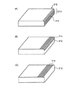
図4は、第1排紙トレイ210に設けられた扉214の開閉機構を説明するための模式図である。図4(A)は、扉214が閉じた状態を示している。また、図4(B)は、途中まで開いた状態の扉214を示し、図4(C)に、完全に開いた状態の扉214を示している。このように、図示せぬ駆動機構により、扉がスライドすることにより、取出口212を開閉する。
【0072】
なお、第2排紙トレイ220に設けられた扉222および第3排紙トレイ230に設けられた扉232の開閉機構も図4を参照しつつ説明した第1排紙トレイ210に設けられた扉214の開閉機構と同様である。
【0073】
図5は、印刷データを受信した場合のプリンタ10における画像形成処理を示すフローチャートである。プリンタ10の通信部140は、ネットワークを介してPC3から印刷要求とともに、印刷データを受信する(ステップS100)。次に、トレイ管理部120は、通信部140が受信した印刷データを印刷した印刷済用紙を排出すべき排紙トレイを決定する(ステップS102)。
【0074】
次に、トレイ管理部120は、決定した排紙トレイの排紙トレイIDに対応する暗証コードを生成する(ステップS104)。次に、トレイ管理部120は、生成した暗証コードを通信部140に送る。そして、通信部140は、トレイ管理部120から受け取った暗証コード、および排紙トレイIDを通信ケーブル2を介してPC3に送信する(ステップS106)。すなわち、PC3の利用者に、印刷データに対する暗証コードを通知する。
【0075】
次に、印刷処理部160は、印刷ジョブ管理部150における印刷ジョブ管理にしたがって、印刷データを用紙に印刷する(ステップS108)。そして、印刷データのすべてを用紙に印刷すると(ステップS110,Yes)、プリンタ10の画像形成処理が完了する。
【0076】
図6は、図5において説明した排紙トレイ決定処理(S102)におけるトレイ管理部120の詳細な処理を示すフローチャートである。
【0077】
まず、トレイ決定部122は、排紙トレイユニット110における第1排紙トレイ用紙検知部112、第2排紙トレイ用紙検知部113、および第3排紙トレイ用紙検知部114から用紙の有無を示す信号を受け取る。そして、印刷済用紙の蓄積されていない排紙トレイがある場合には(ステップS120,Yes)、この排紙トレイを印刷済用紙の排出先として選択する。
【0078】
次に、印刷枚数算出部121は、印刷データの印刷に要する印刷枚数を算出する(ステップS122)。次に、トレイ決定部122は、印刷データの印刷に要する印刷枚数分を排出可能な容量の排紙トレイを検索する。トレイ決定部122は、ハードディスク130の蓄積枚数テーブル132において各排紙トレイIDに対応付けられている蓄積可能な最大用紙枚数を参照して、排紙トレイを検索する。
【0079】
例えば、印刷データの印刷枚数が90枚で、第1排紙トレイの最大用紙枚数が100枚、第2排紙トレイの最大用紙枚数が70枚である場合には、当該印刷データに対する排紙トレイとして、第1排紙トレイを決定する。
【0080】
空の排紙トレイのうちに、印刷枚数分を排出可能な排紙トレイが検索された場合には(ステップS124,Yes)、当該排紙トレイを、対象とする印刷データに対する排紙トレイとして決定する(ステップS128)。
【0081】
一方、印刷枚数分を排出可能な排紙トレイがなく(ステップS124,No)、複数の排紙トレイに分割して全印刷枚数分を排出することができる場合には(ステップS126,Yes)、複数の排紙トレイを、対象とする印刷データに対する排紙トレイとして決定する(ステップS128)。そして、図5において説明した暗証コード生成処理(ステップS104)に進む。
【0082】
ここで、複数の排紙トレイに分割した全印刷枚数分を排出することができる場合とは、例えば、第1排紙トレイ112の最大用紙蓄積枚数が100枚、第2排紙トレイ113の最大用紙蓄積枚数が70枚であって、かつ全印刷枚数が120枚と算出された場合である。この場合、第1排紙トレイ112と、第2排紙トレイ113が空の状態であれば、これら2つの排紙トレイに120枚を分割して排出することにより、全印刷枚数を排出することができる。
【0083】
また、ステップS120において空のトレイがない場合、すなわち、第1排紙トレイ112、第2排紙トレイ113、および第3排紙トレイ114のすべての排紙トレイに印刷済用紙が蓄積されている状態にある場合には(ステップS120,No)、通信部140を介して、印刷データを印刷できない旨を示す印刷不可情報をPC3に送信し(ステップS130)、処理を中止する。
【0084】
また、ステップS126において、複数の排紙トレイに分割しても全印刷枚数分を排紙トレイに排出することができない場合には(ステップS126,No)、同様に、通信部140を介して、印刷データを印刷できない旨を示す印刷不可情報をPC3に送信し(ステップS130)、印刷処理を中止する。
【0085】
図7は、図5における暗証コード生成処理(ステップS104)でのトレイ管理部120における詳細な処理を示すフローチャートである。
【0086】
排紙トレイが決定されると、暗証コード生成部123は、決定された排紙トレイの排紙トレイIDに対応する暗証コードを生成する(ステップS140)。本実施の形態における暗証コード生成部123は、ランダムな整数からなる暗証コードを生成する。暗証コード生成部123は、生成した暗証コードと、ハードディスク130に記憶されている暗証コードとを比較し、同一の暗証コードがハードディスク130に記憶されている場合には(ステップS142,Yes)、再びステップS140に戻り、前回と異なる暗証コードを生成する。
【0087】
一方、同一の暗証コードが、ハードディスク130に記憶されていない場合には(ステップS142,No)、暗証コードをハードディスク130に記憶する(ステップS144)。このとき、暗証コード対応テーブル134において、暗証コードと、当該暗証コードに対応する排紙トレイIDとを対応付ける。なお、本実施の形態においては、さらに、印刷データID、およびジョブIDを暗証コードにさらに対応付ける。
【0088】
以上の処理が完了すると、図5を参照しつつ説明した暗証コード通知処理(ステップS106)に進む。
【0089】
このように、本実施の形態において、ユーザ認証に利用する暗証コードは、各ユーザに割り当てられたユーザ固有の情報ではなく、印刷指示を受信する毎に生成されるランダムな情報である。そして、このランダムな情報である暗証コードを、印刷指示を出したユーザに通知し、この暗証コードによりユーザを認証する。これによれば、予め各ユーザに固有の暗証コードを設定することなく、ユーザ認証を行うことができる。また、これにより、暗証コードを予め設定している一定の者しか、本システムを利用できないという不都合を解消することができる。
【0090】
さらに、本実施の形態における暗証コードは、ランダムな情報であるので、ユーザ固有の暗証コードを利用してユーザ認証を行う場合に比べてセキュリティを向上させることができる。
【0091】
図8は、プリンタ10のトレイ開放処理を示すフローチャートである。利用者が、操作パネル170を介して排紙トレイIDを入力すると、取得部124は、暗証コードを取得する(ステップS200)。次に、トレイ制御部125は、取得部124が取得した排紙トレイIDにより特定される排紙トレイの使用状況を確認する。当該排紙トレイへの印刷済用紙の排出が完了している場合には(ステップS202)、操作パネル170に暗証コード入力画面を表示させる(ステップS204)。図9に暗証コード入力画面を示す。利用者は、画面の表示内容に従って、プリンタ10からPC3に送信された暗証コードを入力する。
【0092】
利用者から暗証コードが入力されると(ステップS206,Yes)、トレイ制御部125は、入力された暗証コードおよびトレイIDを、通信部140を介してPC3に送信した暗証コードおよびトレイIDと照合する(ステップS108)、照合の結果、両者が一致した場合には(ステップS210,Yes)、トレイ制御部125は、排紙トレイユニット110の取出口開放部111に対して当該排紙トレイの開放命令を送る。取出口開放部111は、開放命令を受け取ると、指定された排紙トレイの扉を開く(ステップS212)。
【0093】
そして、利用者が、排紙トレイから印刷済用紙を取り除くと、排紙トレイ用紙検知部は、トレイが空になったことを検知する(ステップS214,Yes)。この場合、トレイ制御部125は、印刷完了検知部115から、トレイが空である旨を示す情報を受け取る。トレイ制御部125は、トレイが空である旨を示す信号を受け取ると、当該トレイIDに対応付けてハードディスク130に記憶されている、暗証コードを消去する(ステップS216)。このとき、ともにトレイIDに対応付けられている、印刷データID、およびジョブIDも消去する。以上で、排紙トレイ制御処理が完了する。
【0094】
なお、ステップS202において、対象となる排紙トレイに印刷済用紙が蓄積されていない場合には(ステップS202,No)、利用者から指定された排紙トレイに印刷済用紙が蓄積されていない旨を操作パネル170に表示させ(ステップS220)、処理は中止される。図10は、このとき操作パネル170に表示される画面を示している。
【0095】
また、利用者から入力された暗証コードおよびトレイIDが、ハードディスク130に記憶されている暗証コードおよびトレイIDの対応と一致しない場合には、一致しない旨を操作パネルに表示させ(ステップS222)、処理は中止される。
【0096】
図11は、プリンタ10のハードウェア構成を示すブロック図である。プリンタ10は、端末装置インターフェース(I/F)5と、CPU6と、ROM7と、RAM8と、操作パネル170と、パネルインターフェース(I/F)9と、ハードディスク(HDD)130と、HDDインターフェース(I/F)13と、印刷処理部160と、印刷エンジンインターフェース(I/F)11と、排紙トレイユニット110と、トレイエンジンインターフェース(I/F)12とを有している。
【0097】
ハードディスク130は、大容量の不揮発性メモリであって、蓄積された印刷データを保持する。
【0098】
印刷処理部160は、図示せぬ感光体上に静電潜像を作り、現像し、また図示せぬ給紙部より転写紙を給紙し、転写及び定着することにより、印刷用紙に画像を形成する。すなわち、詳細な説明中に記載する印刷処理部160は、本発明における印刷手段を構成する。
【0099】
CPU6は、PC3から送られてくる印刷データを受信し、展開処理して、RAM8に格納し、またRAM8の保持された印刷データを印刷処理部160に送る制御機構である。
【0100】
端末装置I/F5は、PC3とのインターフェースである。端末装置I/F5は、PC3から印刷データや印刷指示などの情報を受け取る。CPU6は、ROM7やRAM8に記憶されるプログラムに従って印刷データ等のデータを処理する。ROM7は、データの管理や、操作パネル170、印刷処理部160など周辺モジュールを制御するためのメインとなるプログラムが格納されている。
【0101】
RAM8は、CPU6が処理する際のワークメモリや、ページ単位に管理して一時記憶するページバッファ、ページバッファに記憶されたデータを実際の印字パターンに変換し、印刷データを記憶するビットマップメモリ等さまざまな記憶領域として使われる。
【0102】
パネルI/F9は操作パネル170とのインターフェース部である。データベースI/F13はハードディスク130とのインターフェース部である。印刷エンジンユニットI/F11は、CPU6などから印刷処理部160への制御信号やビデオ信号、印刷処理部160からCPU6などへのステータス信号など、各信号送受信のためのインターフェース部である。
【0103】
先に述べたプリンタ10における画像形成処理を実行する画像形成プログラムは、インストール可能な形式又は実行可能な形式のファイルでCD−ROM、フロッピー(R)ディスク(FD)、DVD等のコンピュータで読み取り可能な記録媒体に記録されて提供される。
【0104】
また、本実施形態の画像形成プログラムを、インターネット等のネットワークに接続されたコンピュータ上に格納し、ネットワーク経由でダウンロードさせることにより提供するように構成しても良い。
【0105】
この場合には、画像形成プログラムは、プリンタ10において上記記録媒体から読み出して実行することにより主記憶装置上にロードされ、上記ソフトウェア構成で説明した各部が主記憶装置上に生成されるようになっている。
【0106】
以上述べたプリンタ10の画像形成処理は、インストール可能な形式又は実行可能な形式のファイルでCD−ROM、フロッピー(R)ディスク、DVD等のコンピュータで読み取り可能な記録媒体に記録されて提供される。
【0107】
また、本実施形態の画像形成プログラムを、インターネット等のネットワークに接続されたコンピュータ上に格納し、ネットワーク経由でダウンロードさせることにより提供するように構成しても良い。
【0108】
本実施形態にかかる画像形成プログラムは、プリンタ10で上記記録媒体から読み出して実行することにより主記憶装置上にロードされ、上記ソフトウェア構成で説明した各部が主記憶装置上に生成されるようになっている。
【0109】
(実施の形態2)
次に、実施の形態2にかかる画像形成システム1について説明する。実施の形態2にかかる画像形成システム1は、印刷データの印刷処理が完了した時点で、暗証コードを生成し、利用者のPC3に暗証コード等を送信する。この点で、実施の形態2にかかる画像形成システム1は、実施の形態1にかかる画像形成システム1と異なる。
【0110】
以下、図12を参照しつつ、実施の形態2にかかるプリンタ10における画像形成処理について説明する。
【0111】
まず、プリンタ10の通信部140は、実施の形態1の場合と同様に、通信ケーブル2を介してPC3から印刷要求とともに、印刷データを受信する(ステップS200)。そして、トレイ管理部120は、通信部140が受信した印刷データを印刷した印刷済用紙を排出すべき排紙トレイを決定する(ステップS202)。
【0112】
次に、印刷処理部160は、印刷ジョブ管理部150における印刷ジョブ管理にしたがって、印刷データを用紙に印刷する(ステップS204)。そして、印刷データのすべてを用紙に印刷すると(ステップS206,Yes)、トレイ管理部120は、印刷済用紙を排出した排紙トレイの排紙トレイIDに対応する暗証コードを生成する(ステップS212)。なお、暗証コード生成処理(ステップS212)は、実施の形態1において図7を参照しつつ説明したステップS104における暗証コード生成処理と同様である。
【0113】
次に、通信部140は、トレイ管理部120から受け取った暗証コードおよび排紙トレイIDを通信ケーブル2を介してPC3に送信する(ステップS214)。以上でプリンタ10の画像形成処理が完了する。
【0114】
このように、実施の形態2にかかるプリンタ10は、印刷データに対する印刷処理が完了した時点で暗証コードを生成する。
【0115】
一方、印刷処理部160が印刷処理を行っている途中で、排紙トレイユニット110のエラー監視部116がエラーを検知すると(ステップS206,No、ステップS208,Yes)、通信部140は、エラーが発生した旨を示すエラー情報をPC3に送信する(ステップS210)。そして、ステップS212へ進む。
【0116】
このように、エラーが発生した場合には、印刷処理が完了する前に、利用者に暗証コードを通知するので、利用者は、エラー発生までに印刷が完了した印刷済用紙を取り出すことができる。
【0117】
また、印刷データの印刷の途中で、印刷済用紙が排紙トレイの最大用紙枚数を越えた場合には(ステップS206,No、ステップS208,No)、トレイ管理部120は、再度空きの排紙トレイを決定し(ステップS202)、印刷処理部160は、印刷処理を再開する(ステップS204)。
【0118】
図13は、図12において説明した排紙トレイ決定処理(ステップS202)におけるトレイ管理部120の詳細な処理を示すフローチャートである。
【0119】
まず、トレイ決定部122は、排紙トレイユニット110における第1排紙トレイ用紙検知部112、第2排紙トレイ用紙検知部113、および第3排紙トレイ用紙検知部114から用紙の有無を示す信号を受け取る。そして、印刷済用紙の蓄積されていない排紙トレイがある場合には(ステップS220,Yes)、この排紙トレイを印刷済用紙の排出先として決定する(ステップS222)。
【0120】
一方、印刷枚数分を排出可能な排紙トレイがない場合には(ステップS220,No)、通信部140を介して、印刷データを印刷できない旨を示す印刷不可情報をPC3に送信する(ステップS224)。以上の処理が完了すると、図12を参照しつつ説明したステップS204へ進む。
【0121】
このように、実施の形態2にかかる画像形成システム1においては、印刷ジョブが完了した後に、暗証コードを送信するので、利用者は、暗証コードを受信した場合に、印刷が完了したことを知ることができる。
【0122】
また、他の例としては、暗証コード送信処理(ステップS214)において、暗証コードおよび排紙トレイIDとともに、印刷データの出力が完了した旨を示す印刷完了情報を送信してもよい。
【0123】
なお、実施の形態2にかかる画像形成システム1の上記以外の構成および動作は、実施の形態1にかかる画像形成システム1の構成および動作と同様である。
【0124】
(実施の形態3)
次に、実施の形態3にかかる画像形成システム1について説明する。実施の形態3にかかる画像形成システム1においては、PC3が暗証コードを生成する。この点で、実施の形態3にかかる画像形成システム1は、プリンタ10が暗証コードを送信してPC3に送信する実施の形態1にかかる画像形成システム1および実施の形態2にかかる画像形成システム1と異なっている。
【0125】
図14は、実施の形態3にかかる画像形成システム1の全体構成を示す図である。実施の形態3にかかるプリンタ10は、暗証コード生成部123を有さない。この点で、実施の形態3にかかるプリンタ10は、実施の形態1にかかるプリンタ10および実施の形態2にかかるプリンタ10と異なっている。
【0126】
実施の形態3にかかるPC3は、通信部31と、暗証コード生成部32と、ハードディスク33とを有している。
【0127】
通信部31は、通信ケーブル2を介してプリンタ10と情報を送受信する。ハードディスク33は、各端末装置に固有の識別情報である端末IDを記憶している。暗証コード生成部32は、通信部31を介してプリンタ10から受信した排紙トレイIDと、ハードディスク33に記憶されている端末IDに基づいて暗証コードを生成する。具体的には、排紙トレイIDに対応する暗証コードを生成し、生成した暗証コードの先頭に端末IDを付与する。すなわち、端末IDが付与されたものを暗証コードとする。このように、暗証コードには、所定の規則に従って付与された端末IDが含まれている。ここで、所定の規則は、画像形成システム1が有するすべてのPC3に対して同様に設定されている。このように、画像形成システム1に含まれるすべてのPC3は、それぞれ固有の端末IDを所定の規則に従って含んだ暗証コードを生成するので、各端末装置が同一の暗証コードを生成するのを避けることができる。
【0128】
図15は、実施の形態3にかかる画像形成システム1における画像形成処理を示すフローチャートである。
【0129】
PC3は印刷データを生成する(ステップS300)。そして、生成した印刷データおよび当該印刷データに対する印刷要求をプリンタ10に送信する(ステップS302)。プリンタ10の通信部140が印刷データと印刷要求を受信すると、トレイ管理部120は、排紙トレイを決定する(ステップS304)。そして、通信部140は、トレイ管理部120によって決定された排紙トレイの排紙トレイIDを印刷要求の送信元であるPC3に送信する(ステップS306)。
【0130】
PC3は、排紙トレイIDを受信すると、受信した排紙トレイIDとハードディスク33に保持されている端末IDとに基づいて、暗証コードを生成する(ステップS308)。
【0131】
ここで、端末IDが「A001」である場合の暗証コードの生成処理について説明する。まず暗証コード生成部32は、ランダムな暗証コードを生成する。生成された暗証コードが、「09081」である場合、生成された暗証コードにさらに端末ID「A001」を付与し、「A00109081」を暗証コードとする。
【0132】
このように、各端末装置は、それぞれランダムな暗証コードを生成するが、その先頭に、各端末装置固有の端末IDを付与するので、プリンタ10が複数の端末装置から同一の暗証コードを受信するのを避けることができる。
【0133】
次に、PC3の通信部31は、暗証コード生成部32によって生成された暗証コードを通信ケーブル2を介してプリンタ10に送信する(ステップS310)。
【0134】
一方、プリンタ10のトレイ管理部120は、トレイ決定部122において決定された排紙トレイの排紙トレイIDを、通信部140が受信した印刷データを識別する印刷データIDに対応付けてハードディスク130に記憶させる。
【0135】
さらに、プリンタ10の通信部140が暗証コードを受信すると、トレイ管理部120は、先に送信した排紙トレイIDに対応付けて暗証コードをハードディスク130に記憶させる(ステップS330)。
【0136】
次に、印刷処理部160は、印刷ジョブ管理部150における印刷ジョブ管理に従って、印刷データを用紙に印刷する(ステップS332)。そして、印刷データのすべてを用紙に印刷すると(ステップS334,Yes)、プリンタ10の画像形成処理が完了する。
【0137】
このように、実施の形態3においては、PC3が暗証コードを生成する。
【0138】
以上、本発明を実施の形態を用いて説明したが、上記実施の形態に多様な変更または改良を加えることができる。
【0139】
そうした第1変更例としては、トレイ決定部122は、当該プリンタ10が取得した印刷データのうち、まだ印刷処理の完了していない印刷データに対して、決定された排紙トレイ以外の排紙トレイを、対象とする印刷データに対する排紙トレイとして決定してもよい。
【0140】
具体的には、まだ印刷処理がされずに、印刷ジョブ管理部150によって管理されている印刷データに対して既に第1排紙トレイが排出先として決定されている場合には、そのとき、第1排紙トレイに用紙が蓄積されていない場合であっても、第1排紙トレイを対象とする印刷データに対する排紙トレイの候補から除外する。
【0141】
これにより、異なる2以上の印刷データが、同時に同一の排紙トレイに蓄積されるのを避けることができる。
【0142】
【発明の効果】
以上説明したように、請求項1にかかる発明によれば、暗証情報生成手段は、排紙トレイ識別情報に対応する暗証情報を生成し、トレイ制御部は、照合手段が、生成された当該暗証情報と利用者から入力された暗証情報の照合に成功した場合に、排紙トレイの取出口の開放を許可するので、暗証情報を取得した者以外の者は、印刷物が蓄積された排紙トレイの取出口を開放することができず、印刷物の機密性を保持することができるという効果を奏する。
【0143】
また、印刷データ毎に暗証情報を生成するので、暗証情報が解読されるおそれもなく、各ユーザに対して固有の暗証情報を割り当てる場合に比べて、より高いセキュリティレベルを保持することができるという効果を奏する。
【0144】
また、暗証情報は、ユーザに固有の情報ではないので、所定の文書を、一定の者以外の者が印刷できないという不都合を解消することができるという効果を奏する。
【0145】
また、請求項2にかかる発明によれば、送信手段は、印刷処理が完了したときに暗証情報を送信するので、利用者は、暗証情報を受信したときに、印刷処理が完了したことを認識することができる。従って、利用者は、画像形成装置の前で、印刷が完了するまで待つ必要がなく、画像形成装置の利便性を向上させることができるという効果を奏する。
【0146】
また、請求項3にかかる発明によれば、送信手段は、印刷処理が完了したときに暗証情報とともに印刷処理が完了した旨を送信するので、利用者は、暗証情報とともに印刷完了した旨の通知を受けることができる。従って、利用者は、画像形成装置の前で、印刷が完了するまで待つ必要がなく、画像形成装置の利便性を向上させることができるという効果を奏する。
【0147】
また、請求項4にかかる発明によれば、送信手段は、排紙トレイが決定されたときに暗証情報を受信するので、利用者は、このタイミングで、暗証情報を取得し、その後、利用者は所望のタイミングで、排紙トレイに蓄積された印刷済用紙を取得することができるという効果を奏する。
【0148】
また、請求項5にかかる発明によれば、印刷データ識別情報に対応する暗証情報を生成するので、暗証情報に対応する印刷データを識別することができる。このため、印刷データ単位で、印刷物を管理することができ、印刷データ単位で、印刷物の機密性を保持することができるという効果を奏する。
【0149】
また、請求項6にかかる発明によれば、ジョブ識別情報に対応する暗証情報を生成するので、暗証情報に対応するジョブを識別することができる。このため、印刷ジョブ単位で、印刷物を管理することができ、印刷ジョブ単位で印刷物の機密性を保持することができるという効果を奏する。
【0150】
また、請求項7にかかる発明によれば、トレイ識別情報と、暗証情報とを対応付ける対応テーブルを備えているので、トレイ制御手段は、対応テーブルにおける対応関係から容易に、開放すべき排紙トレイを特定することができるという効果を奏する。
【0151】
また、請求項8にかかる発明によれば、トレイ決定手段は、用紙検知手段が印刷済用紙が蓄積されていないことを検知した排紙トレイを、印刷データに対する排紙トレイとして決定するので、既に他の印刷データが蓄積されている排紙トレイに、印刷済用紙が排出されるのを避けることができる。このように、一の排紙トレイに、複数の印刷データに対する印刷済用紙が重ねて排出されるのを避けることができるので、印刷物の機密性を保つことができるという効果を奏する。
【0152】
また、請求項9にかかる発明によれば、トレイ決定手段は、印刷処理待ちの状態にある印刷データに対して既に決定された排紙トレイ以外の排紙トレイを、印刷データに対する前記排紙トレイとして決定するので、既に他の印刷データが蓄積されている排紙トレイに、印刷済用紙が、重ねて排出されるのを避けることができる。このように、一の排紙トレイに、複数の印刷データに対する印刷済用紙が排出されるのを避けることができるので、印刷物の機密性を保つことができるという効果を奏する。
【0153】
また、請求項10にかかる発明によれば、印刷枚数算出手段は、印刷データ取得手段が取得した印刷データの印刷に要する印刷枚数を算出し、トレイ決定手段は、印刷枚数算出手段が算出した印刷枚数と、各排紙トレイに蓄積可能な用紙枚数とに基づいて、印刷枚数分を排出可能な排紙トレイを当該印刷データに対する排紙トレイとして決定するので、印刷データに対する印刷枚数をすべて、暗証情報により開放可能な一の排紙トレイに排出することができるという効果を奏する。
【0154】
また、請求項11にかかる発明によれば、トレイ決定手段は、印刷枚数が排紙トレイの容量よりも多い場合には、複数の排紙トレイを印刷データの排紙トレイとして決定し、暗証情報生成手段は、複数の排紙トレイのトレイ識別情報に対応する暗証情報を生成することができるので、印刷済用紙が複数の排紙トレイに分割して排出された場合には、一の暗証情報により当該複数の排紙トレイを開放することができる。従って、一の排紙トレイに排出された場合と同様に、印刷物の機密性を保つことができるという効果を奏する。
【0155】
また、請求項12にかかる発明によれば、送信手段は、エラー監視手段がエラーを検知すると、暗証情報を送信するので、利用者は、エラーが検知された時点で、暗証情報を取得することができる。これにより、エラーが発生する以前に既に印刷された印刷済用紙を取り出すことができるという効果を奏する。
【0156】
また、請求項13にかかる発明によれば、暗証情報生成手段は、排紙トレイ識別情報に対応する暗証情報を生成し、トレイ制御部は、照合手段が、生成された当該暗証情報と利用者から入力された暗証情報の照合に成功した場合に、排紙トレイの取出口の開放を許可するので、暗証情報を取得した者以外の者は、印刷物が蓄積された排紙トレイの取出口を開放することができず、印刷物の機密性を保持することができるという効果を奏する。
【0157】
また、請求項14にかかる発明によれば、複数の端末はそれぞれに固有の端末装置識別情報を含む暗証情報を生成するので、画像形成装置は、複数の端末装置から同一の暗証情報を取得するのを避けることができるという効果を奏する。
【0158】
また、請求項15にかかる発明によれば、暗証情報生成手段は、排紙トレイ識別情報に対応する暗証情報を生成し、トレイ制御部は、照合手段が、生成された当該暗証情報と利用者から入力された暗証情報の照合に成功した場合に、排紙トレイの取出口の開放を許可するので、暗証情報を取得した者以外の者は、印刷物が蓄積された排紙トレイの取出口を開放することができず、印刷物の機密性を保持することができるという効果を奏する。
【0159】
また、請求項16にかかる発明によれば、排紙トレイ識別情報に対応する暗証情報を生成し、生成された当該暗証情報と利用者から入力された暗証情報の照合に成功した場合に、排紙トレイの取出口の開放を許可するので、暗証情報を取得した者以外の者は、印刷物が蓄積された排紙トレイの取出口を開放することができず、印刷物の機密性を保持することができるという効果を奏する。
【0160】
また、請求項17にかかる発明によれば、排紙トレイ識別情報に対応する暗証情報を生成し、生成された当該暗証情報と利用者から入力された暗証情報の照合に成功した場合に、排紙トレイの取出口の開放を許可するので、暗証情報を取得した者以外の者は、印刷物が蓄積された排紙トレイの取出口を開放することができず、印刷物の機密性を保持することができるという効果を奏する。
【図面の簡単な説明】
【図1】実施の形態1にかかる画像形成システム1の全体図である。
【図2】図1において説明した暗証コード対応テーブル134のデータ構成を模式的に示す図である。
【図3】プリンタ10の外観図である。
【図4】第1排紙トレイ210に設けられたトレイ212の開閉機構を説明するための模式図である。
【図5】印刷データを受信した場合のプリンタ10における画像形成処理を示すフローチャートである。
【図6】図5において説明した排紙トレイ決定処理(S102)におけるトレイ管理部120の詳細な処理を示すフローチャートである。
【図7】図5における暗証コード生成処理(ステップS104)でのトレイ管理部120における詳細な処理を示すフローチャートである。
【図8】プリンタ10のトレイ開放処理を示すフローチャートである。
【図9】暗証コード入力画面を示す図である。
【図10】操作パネル170の表示画面を示す図である。
【図11】プリンタ10のハードウェア構成を示すブロック図である。
【図12】実施の形態2にかかるプリンタ10における画像形成処理を示すフローチャートである。
【図13】図12において説明した排紙トレイ決定処理(ステップS202)におけるトレイ管理部120の詳細な処理を示すフローチャートである。
【図14】実施の形態3にかかる画像形成システム1の全体構成を示す図である。
【図15】実施の形態3にかかる画像形成システム1における画像形成処理を示すフローチャートである。
【符号の説明】
1 画像形成システム
2 通信ケーブル
3a,3b,3c 端末装置
5 端末装置I/F
6 CPU
7 ROM
8 RAM
9 パネルI/F
10 画像形成装置
11 印刷エンジンI/F
12 トレイエンジンI/F
13データベースI/F
31 通信部
32 暗証コード生成部
33 保持部
110 排紙トレイユニット
111 取出口開放部
112 排紙トレイ用紙検知部
113 排紙トレイ用紙検知部
114 排紙トレイ用紙検知部
115 印刷完了検知部
116 エラー監視部
120 トレイ管理部
121 印刷枚数算出部
122 トレイ決定部
123 暗証コード生成部
124 取得部
125 トレイ制御部
130 データベース
132 蓄積枚数テーブル
134 暗証コード対応テーブル
140 通信部
150 印刷ジョブ管理部
160 印刷処理部
170 操作パネル
210 第1排紙トレイ
220 第2排紙トレイ
230 第3排紙トレイ
212,222,232 取出口
214,224,234 扉[0001]
TECHNICAL FIELD OF THE INVENTION
The present invention relates to an image forming apparatus, an image forming system, an image forming method, and an image forming program.
[0002]
[Prior art]
With the recent spread of LAN (Local Area Network), one image forming apparatus and a plurality of terminal apparatuses may be connected to a network, and a plurality of terminal apparatuses may share and use one image forming apparatus. Is becoming more common. As such an image forming apparatus, there is a multifunction peripheral in which functions of respective apparatuses such as a printer, a printer, a copier, a facsimile, and a scanner are housed in a single housing.
[0003]
Further, there is known an image forming apparatus having a mechanism for sorting and outputting print data to a plurality of sorters. According to this, even when a plurality of users share and use the image forming apparatus, the user can easily determine and acquire his or her own print data. However, when a plurality of persons share the image forming apparatus, the contents of the printed matter are easily known to others, and thus there is a problem in managing confidential documents and the like.
[0004]
In order to solve such a problem, for example, a technique of starting printing only when a password set by a user is input to an image forming apparatus is disclosed (for example, Patent Document 1).
[0005]
Further, a method is known in which only a print user who has been authenticated by fingerprint authentication is permitted to use a network device (for example, Patent Document 2). According to this method, a person other than the printing user cannot take out the printed material, so that the confidentiality of the document can be maintained.
[0006]
[Patent Document 1]
JP 2001-322337 A
[Patent Document 2]
JP 2001-265739 A
[0007]
[Problems to be solved by the invention]
However, in the authentication method using the password, after the password is input, the printed matter is discharged to the paper discharge tray, so that the printed matter is placed in a state where an unspecified person can see it. For this reason, the user must monitor the paper discharge tray from the start to the end of printing, and there is a problem that the user is restrained during the printing process. Further, every time printing is performed, the user has to transmit the personal identification code together with the print data, which causes a problem that the printing operation becomes complicated.
[0008]
Further, according to the method based on fingerprint authentication, a person other than the print user cannot take out the printed matter, so that the confidentiality of the printed matter can be maintained. However, the reason that use is always permitted only to the print user is inflexible and sometimes inconvenient.
[0009]
The present invention has been made in view of the above, and is capable of maintaining the confidentiality of a printed material without restricting the user's time, and having a flexible image forming apparatus, an image forming system, an image forming method, and an image. The aim is to obtain a forming program.
[0010]
[Means for Solving the Problems]
In order to achieve the above object, the invention according to
[0011]
According to the first aspect of the present invention, the password information generating means generates password information corresponding to the paper discharge tray identification information, and the tray control section determines that the collating means inputs the generated password information and the user from the user. If the collation of the password information is successful, the opening of the exit of the paper output tray is permitted, so that anyone other than the person who acquired the password information opens the exit of the output tray in which the printed matter is stored. And the confidentiality of the printed matter can be maintained.
[0012]
Further, since the security information is generated for each print data, there is no possibility that the security information is decrypted, and a higher security level can be maintained as compared with a case where unique security information is assigned to each user.
[0013]
Further, since the password information is not information unique to the user, it is possible to eliminate the inconvenience that a predetermined document cannot be printed by a person other than a certain person.
[0014]
According to a second aspect of the present invention, in the image forming apparatus according to the first aspect, the transmitting unit transmits the personal identification information when the printing unit completes a print process on the print data. It is characterized by the following.
[0015]
According to the second aspect of the present invention, the transmitting unit transmits the password information when the printing process is completed. Therefore, when the user receives the password information, the user recognizes that the printing process is completed. Can be. Therefore, the user does not need to wait until printing is completed in front of the image forming apparatus, and the convenience of the image forming apparatus can be improved.
[0016]
According to a third aspect of the present invention, in the image forming apparatus according to the second aspect, when the print processing on the print data is completed, the transmission unit completes the output together with the password information. Is transmitted.
[0017]
According to the third aspect of the present invention, when the printing process is completed, the transmitting unit transmits the completion of the printing process together with the password information, so that the user receives the notification of the printing completion together with the password information. be able to. Therefore, the user does not need to wait until printing is completed in front of the image forming apparatus, and the convenience of the image forming apparatus can be improved.
[0018]
The invention according to a fourth aspect is the image forming apparatus according to the first aspect, wherein the transmission unit transmits the password information when the tray determination unit determines the discharge tray. It is characterized by.
[0019]
According to the fourth aspect of the present invention, the transmitting means receives the password information when the paper discharge tray is determined, so that the user acquires the password information at this timing, and thereafter, the user obtains the desired password. At this timing, the printed paper accumulated in the paper discharge tray can be obtained.
[0020]
According to a fifth aspect of the present invention, in the image forming apparatus according to any one of the first to fourth aspects, the password information generation unit corresponds to print data identification information for identifying the print data. The password information is generated.
[0021]
According to the fifth aspect of the present invention, since the password information corresponding to the print data identification information is generated, the print data corresponding to the password information can be identified. For this reason, the printed matter can be managed in print data units, and the confidentiality of the printed matter can be maintained in print data units.
[0022]
According to a sixth aspect of the present invention, there is provided the image forming apparatus according to any one of the first to fifth aspects, wherein the password information generation unit is configured to execute the print data acquisition by the print data acquisition unit. And generating the personal identification information corresponding to the job identification information for identifying the print processing, which is assigned to the personal identification information.
[0023]
According to the invention of
[0024]
According to a seventh aspect of the present invention, in the image forming apparatus according to any one of the first to sixth aspects, the tray identification information of the discharge tray determined by the tray determination unit and the password. The image forming apparatus further includes a correspondence table for associating the password information with the password information generated by the information generation unit, wherein the tray control unit specifies the paper discharge tray from the password information based on the correspondence table.
[0025]
According to the seventh aspect of the present invention, since the correspondence table for associating the tray identification information with the password information is provided, the tray control means can easily specify the discharge tray to be opened from the correspondence in the correspondence table. can do.
[0026]
The invention according to claim 8 is the image forming apparatus according to any one of
[0027]
According to the eighth aspect of the present invention, the tray determination unit determines the paper output tray for which the paper detection unit has detected that the printed paper is not stored as the paper output tray for the print data. It is possible to prevent printed paper from being discharged to a paper discharge tray in which print data is stored. In this way, it is possible to prevent the printed papers for the plurality of print data from being discharged one upon another to a predetermined paper discharge tray, so that the confidentiality of the printed matter can be maintained.
[0028]
Further, according to a ninth aspect of the present invention, in the image forming apparatus according to any one of the first to eighth aspects, the tray determination unit has already performed the print data waiting for a print process. A discharge tray other than the determined discharge tray is determined as the discharge tray for the print data.
[0029]
According to the ninth aspect of the present invention, the tray determination unit determines a paper output tray other than the paper output tray already determined for the print data in a print processing waiting state as the paper output tray for the print data. Therefore, it is possible to prevent the printed paper from being discharged to the discharge tray in which other print data is already stored.
In this way, it is possible to prevent the printed paper for a plurality of print data from being discharged to the predetermined paper discharge tray, so that the confidentiality of the printed matter can be maintained.
[0030]
The invention according to a tenth aspect is the image forming apparatus according to any one of the first to ninth aspects, wherein the number of prints required for printing the print data acquired by the print data acquisition unit is calculated. The apparatus further includes a printed sheet number calculating unit, and the tray determining unit can discharge the printed sheet number based on the calculated sheet number calculated by the printed sheet number calculating unit and a maximum sheet number that can be stored in each of the output trays. The above-mentioned paper discharge tray is determined as the paper discharge tray for the print data.
[0031]
According to the tenth aspect of the present invention, the print number calculating means calculates the number of prints required for printing the print data obtained by the print data obtaining means, and the tray determining means calculates the number of prints calculated by the print number calculating means. Based on the number of sheets that can be stored in each sheet ejection tray, the sheet ejection tray capable of ejecting the number of prints is determined as the sheet ejection tray for the print data. It can be discharged to a predetermined discharge tray that can be opened.
[0032]
According to an eleventh aspect of the present invention, in the image forming apparatus according to the tenth aspect, when the number of printed sheets is larger than the maximum number of sheets in the discharge tray, The paper ejection tray is determined as the paper ejection tray of the print data, and the password information generating means generates the password information corresponding to the tray identification information of the plurality of paper ejection trays.
[0033]
According to the eleventh aspect of the present invention, when the number of printed sheets is larger than the capacity of the paper discharge tray, the tray determination means determines the plurality of paper discharge trays as paper discharge trays for print data, Can generate password information corresponding to the tray identification information of a plurality of paper output trays. Therefore, when printed paper is divided and output to a plurality of paper output trays, A plurality of discharge trays can be opened. Therefore, the confidentiality of the printed matter can be maintained as in the case where the printed matter is discharged to a predetermined discharge tray.
[0034]
According to a twelfth aspect of the present invention, in the image forming apparatus according to any one of the first to eleventh aspects, the image forming apparatus further includes an error monitoring unit that manages a printing process of the printing unit. When the error monitoring unit detects an error, the password information is transmitted.
[0035]
According to the twelfth aspect of the present invention, when the error monitoring means detects the error, the transmitting means transmits the password information, so that the user can acquire the password information at the time when the error is detected. . As a result, it is possible to take out the printed paper that has been printed before the occurrence of the error.
[0036]
According to another aspect of the present invention, there is provided an image forming apparatus having a plurality of discharge trays for storing sheets on which print data is printed, and an image forming system including a terminal device for transmitting the print data to the image forming apparatus. Wherein the image forming apparatus identifies a discharge tray from which the printed paper on which the print data has been printed is to be discharged and a discharge tray determined by the tray determination means. Transmitting means for transmitting tray identification information to the terminal device, the terminal device receiving means for receiving the tray identification information from the image forming apparatus, and corresponding to the tray identification information received by the receiving means; Password information generating means for generating password information to be transmitted, and transmitting means for transmitting the password information to the image forming apparatus, wherein the image forming apparatus comprises: Receiving means for receiving the password information from the user, input receiving means for receiving the input of the password information from the user, the password information the input receiving means has received the input, and the password information received by the receiving means, Collating means for collating, and, if collation by the collating means succeeds, a tray control means for specifying the paper discharge tray from the password information and permitting opening of the specified outlet of the paper discharge tray. It is characterized by having.
[0037]
According to the thirteenth aspect of the present invention, the password information generation means generates password information corresponding to the paper discharge tray identification information, and the tray control section allows the collation means to input the generated password information and the input from the user. If the collation of the password information is successful, the opening of the exit of the paper output tray is permitted, so that anyone other than the person who obtained the password information opens the exit of the paper output tray in which the printed matter is stored. And the confidentiality of the printed matter can be maintained.
[0038]
According to a fourteenth aspect of the present invention, in the image forming system according to the thirteenth aspect, the image forming system includes a plurality of terminal devices, and the terminal device identifies a terminal device that identifies the terminal device. Further comprising a terminal device identification information holding unit for holding information, wherein the password information generation unit generates the password information including the terminal device identification information held in the terminal device identification information holding unit. I do.
[0039]
According to the fourteenth aspect of the present invention, since the plurality of terminals generate the password information including the unique terminal device identification information, the image forming apparatus can acquire the same password information from the plurality of terminal devices. Can be avoided.
[0040]
According to a fifteenth aspect of the present invention, there is provided an image forming apparatus having a plurality of paper output trays for storing paper on which print data obtained from a terminal device via a network is printed, wherein the print data is printed. Tray determining means for determining the paper discharge tray from which used paper is to be discharged, transmitting means for transmitting tray identification information for identifying the paper discharge tray determined by the tray determining means to the terminal device, As a reply to the transmitted tray identification information, a receiving unit that receives password information generated by the terminal device and that corresponds to the tray identification information, and an input receiving unit that receives input of the password information from the user, Collating means for collating the password information received by the input means with the password information received by the receiving means; Upon successful verification by stage, to identify the sheet discharge tray from the personal identification information, characterized by comprising a tray control means for permitting opening of the takeout of the paper discharge tray identified.
[0041]
According to the fifteenth aspect of the present invention, the password information generation means generates password information corresponding to the paper discharge tray identification information, and the tray control section allows the collation means to input the generated password information and the input from the user. If the collation of the password information is successful, the opening of the exit of the paper output tray is permitted, so that anyone other than the person who obtained the password information opens the exit of the paper output tray in which the printed matter is stored. And the confidentiality of the printed matter can be maintained.
[0042]
The invention according to claim 16 is an image forming method in an image forming apparatus having a plurality of paper output trays for storing paper on which print data obtained from a terminal device via a network is printed, wherein the print data is A tray determining step of determining the discharge tray from which printed printed paper is to be discharged, and password information generation for generating password information corresponding to tray identification information for identifying the discharge tray determined in the tray determining step A step of notifying a user of the password information generated in the step of generating the password information, a step of receiving an input of the password information from the user, and a step of receiving the input in the step of receiving the password. Collation for collating information with the password information notified to the user in the notification step And a tray control step of, when the collation in the collation step is successful, specifying the paper discharge tray from the password information and permitting the specified paper discharge tray to be opened. I do.
[0043]
According to the sixteenth aspect of the present invention, the personal identification information corresponding to the paper discharge tray identification information is generated, and if the generated password information and the password information input by the user are successfully collated, the paper discharge tray is determined. Is permitted to be opened, so that anyone other than the person who has obtained the password information cannot open the outlet of the output tray in which the printed matter is stored, and the confidentiality of the printed matter can be maintained. .
[0044]
According to a seventeenth aspect of the present invention, a computer executes a management process of the discharge tray in an image forming apparatus having a plurality of discharge trays for storing sheets on which print data obtained from a terminal device via a network is printed. A tray determining step of determining the discharge tray from which printed paper on which the print data is printed is to be discharged; and a tray identification for identifying the discharge tray determined in the tray determining step. A password information generating step of generating password information corresponding to information, a transmitting step of transmitting the password information generated in the password information generating step to the terminal device, and an input receiving receiving an input of the password information from a user The password information received in the input receiving step in the input receiving step; A collation step of collating the password information transmitted in the transmission step, and, if the collation in the collation step is successful, specifying the paper discharge tray from the password information, and opening the specified paper discharge tray outlet. And allowing the computer to execute a tray control step of permitting
[0045]
According to the seventeenth aspect of the present invention, the password information corresponding to the paper discharge tray identification information is generated, and if the generated password information is successfully collated with the password information input by the user, the paper discharge tray is generated. Is permitted to be opened, so that anyone other than the person who has obtained the password information cannot open the outlet of the output tray in which the printed matter is stored, and the confidentiality of the printed matter can be maintained. .
[0046]
BEST MODE FOR CARRYING OUT THE INVENTION
Hereinafter, preferred embodiments of an image forming apparatus, an image forming system, an image forming method, and an image forming program according to the present invention will be described in detail with reference to the accompanying drawings.
[0047]
(Embodiment 1)
FIG. 1 is a diagram showing an overall configuration of an
[0048]
The
[0049]
The
[0050]
The
[0051]
The first discharge tray
[0052]
The take-out
[0053]
The print completion detection unit 115 detects that all the print data has been printed on the paper and has been discharged to the paper discharge tray. The error monitor 116 monitors an error in the printing process. Specifically, the occurrence of errors that can be recovered by the user, such as a paper jam or running out of paper, is monitored.
[0054]
[0055]
The
[0056]
The print
[0057]
The
[0058]
The print number calculator 121 calculates the number of prints for the print data based on the print data. The number of prints is the number of sheets required to print all print data.
[0059]
Specifically, the number of prints is calculated based on the number of pages included in the print data. For example, when an instruction to print one page on one sheet is given as a print instruction for print data, the number of pages is the number of prints. In the case where an instruction to print two pages on one sheet is given as a print instruction for print data, half the number of pages of the print data is the number of prints. Further, when the instruction to print on both sides of one sheet is given as a print instruction for the print data, half the number of pages of the print data is the number of prints.
[0060]
The storage number table 132 of the
[0061]
The tray determination unit 122 determines a paper discharge tray for discharging print data. That is, it is determined to which of the first
[0062]
The secret
[0063]
The security code correspondence table 134 of the
[0064]
The
[0065]
FIG. 2 is a diagram schematically showing a data configuration of the personal identification code correspondence table 134 described in FIG.
[0066]
The password code correspondence table 134 includes a discharge tray ID for identifying the
[0067]
As described above, since the paper discharge tray ID and the password are associated in the password code correspondence table 134, the
[0068]
FIG. 3 is a diagram illustrating an appearance of the
[0069]
On one side surface of each of the
[0070]
FIG. 3B is an external view of the first
[0071]
FIG. 4 is a schematic diagram for explaining an opening / closing mechanism of a
[0072]
The opening / closing mechanism of the
[0073]
FIG. 5 is a flowchart illustrating an image forming process in the
[0074]
Next, the
[0075]
Next, the
[0076]
FIG. 6 is a flowchart illustrating the detailed processing of the
[0077]
First, the tray determination unit 122 indicates the presence / absence of paper from the first discharge tray
[0078]
Next, the print number calculator 121 calculates the number of prints required to print the print data (step S122). Next, the tray determination unit 122 searches for a discharge tray having a capacity capable of discharging the number of prints required for printing the print data. The tray determination unit 122 searches for a paper discharge tray by referring to the maximum storable number of paper sheets associated with each paper discharge tray ID in the storage number table 132 of the
[0079]
For example, if the number of print data is 90, the maximum number of sheets in the first discharge tray is 100, and the maximum number of sheets in the second discharge tray is 70, the discharge tray for the print data is The first paper discharge tray is determined.
[0080]
If a discharge tray capable of discharging the number of prints is found in the empty discharge tray (step S124, Yes), the discharge tray is determined as a discharge tray for the target print data. (Step S128).
[0081]
On the other hand, if there is no discharge tray capable of discharging the number of printed sheets (No at Step S124), and the sheet can be divided into a plurality of discharge trays to discharge the entire number of printed sheets (Step S126, Yes), A plurality of discharge trays are determined as discharge trays for the target print data (step S128). Then, the process proceeds to the secret code generation process (step S104) described with reference to FIG.
[0082]
Here, the case where the total number of printed sheets divided into a plurality of discharge trays can be discharged means, for example, that the maximum number of sheets stored in the
[0083]
If there is no empty tray in step S120, that is, printed paper is accumulated in all of the first, second, and
[0084]
If it is determined in step S126 that the total number of printed sheets cannot be discharged to the discharge tray even if the print sheet is divided into a plurality of discharge trays (No in step S126), similarly, the
[0085]
FIG. 7 is a flowchart showing a detailed process in the
[0086]
When the discharge tray is determined, the password
[0087]
On the other hand, when the same password is not stored in the hard disk 130 (No at Step S142), the password is stored in the hard disk 130 (Step S144). At this time, in the personal identification code correspondence table 134, the personal identification code is associated with the discharge tray ID corresponding to the personal identification code. In the present embodiment, the print data ID and the job ID are further associated with the password.
[0088]
When the above process is completed, the process proceeds to the password code notification process (step S106) described with reference to FIG.
[0089]
As described above, in the present embodiment, the personal identification code used for user authentication is not user-specific information assigned to each user, but random information generated each time a print instruction is received. Then, the security code, which is the random information, is notified to the user who issued the print instruction, and the user is authenticated with the security code. According to this, it is possible to perform user authentication without previously setting a personal identification code unique to each user. In addition, it is possible to eliminate the inconvenience that only a certain person who presets the personal identification code can use the present system.
[0090]
Furthermore, since the personal identification code in the present embodiment is random information, security can be improved as compared with a case where user authentication is performed using a personal identification code.
[0091]
FIG. 8 is a flowchart illustrating the tray opening process of the
[0092]
When the password is input by the user (step S206, Yes), the
[0093]
When the user removes the printed paper from the paper output tray, the paper output tray paper detection unit detects that the tray is empty (step S214, Yes). In this case, the
[0094]
In step S202, when the printed paper is not stored in the target discharge tray (No in step S202), the fact that the printed paper is not stored in the discharge tray designated by the user is described. Is displayed on the operation panel 170 (step S220), and the process is stopped. FIG. 10 shows a screen displayed on
[0095]
If the personal identification code and the tray ID input by the user do not match the correspondence between the personal identification code and the tray ID stored in the
[0096]
FIG. 11 is a block diagram illustrating a hardware configuration of the
[0097]
The
[0098]
The
[0099]
The
[0100]
The terminal device I / F5 is an interface with the PC3. The terminal device I / F 5 receives information such as print data and a print instruction from the PC 3. The
[0101]
The RAM 8 includes a work memory for processing by the
[0102]
The panel I /
[0103]
The image forming program for executing the image forming process in the
[0104]
Further, the image forming program of the present embodiment may be stored on a computer connected to a network such as the Internet and provided by being downloaded via the network.
[0105]
In this case, the image forming program is read from the recording medium in the
[0106]
The image forming process of the
[0107]
Further, the image forming program of the present embodiment may be stored on a computer connected to a network such as the Internet and provided by being downloaded via the network.
[0108]
The image forming program according to the present embodiment is loaded onto the main storage device by being read out from the recording medium by the
[0109]
(Embodiment 2)
Next, an
[0110]
Hereinafter, an image forming process in the
[0111]
First, the
[0112]
Next, the
[0113]
Next, the
[0114]
As described above, the
[0115]
On the other hand, if the error monitoring unit 116 of the paper
[0116]
As described above, when an error occurs, the user is notified of the personal identification code before the printing process is completed, so that the user can take out the printed paper that has been printed before the error occurs. .
[0117]
If the number of printed sheets exceeds the maximum number of sheets in the discharge tray during printing of the print data (step S206, No, step S208, No), the
[0118]
FIG. 13 is a flowchart showing a detailed process of the
[0119]
First, the tray determination unit 122 indicates the presence / absence of paper from the first discharge tray
[0120]
On the other hand, if there is no discharge tray capable of discharging the number of prints (step S220, No), print disable information indicating that print data cannot be printed is transmitted to the PC 3 via the communication unit 140 (step S224). ). When the above process is completed, the process proceeds to step S204 described with reference to FIG.
[0121]
As described above, in the
[0122]
As another example, in the personal identification code transmission process (step S214), print completion information indicating that the output of the print data has been completed may be transmitted together with the personal identification code and the discharge tray ID.
[0123]
The configuration and operation of the
[0124]
(Embodiment 3)
Next, an
[0125]
FIG. 14 is a diagram illustrating an overall configuration of the
[0126]
The PC 3 according to the third embodiment includes a
[0127]
The
[0128]
FIG. 15 is a flowchart illustrating an image forming process in the
[0129]
The PC 3 generates print data (Step S300). Then, the generated print data and a print request for the print data are transmitted to the printer 10 (step S302). When the
[0130]
When receiving the paper output tray ID, the PC 3 generates a password based on the received paper output tray ID and the terminal ID held in the hard disk 33 (step S308).
[0131]
Here, a process of generating a personal identification code when the terminal ID is “A001” will be described. First, the secret
[0132]
As described above, each terminal device generates a random personal identification code. At the head of the random identification code, a terminal ID unique to each terminal device is assigned, so that the
[0133]
Next, the
[0134]
On the other hand, the
[0135]
Further, when the
[0136]
Next, the
[0137]
As described above, in the third embodiment, the PC 3 generates the personal identification code.
[0138]
As described above, the present invention has been described using the embodiment. However, various changes or improvements can be added to the above embodiment.
[0139]
As such a first modification, the tray determination unit 122 outputs a print tray other than the determined discharge tray to the print data for which print processing has not been completed among print data acquired by the
[0140]
More specifically, if the first discharge tray has already been determined as the discharge destination for the print data managed by the print
[0141]
Thus, it is possible to prevent two or more different print data from being simultaneously stored in the same discharge tray.
[0142]
【The invention's effect】
As described above, according to the first aspect of the present invention, the password information generation means generates password information corresponding to the paper discharge tray identification information, and the tray control unit determines that the collation means generates the password. If the information and the password entered by the user are successfully collated, the opening of the output tray is permitted.Those other than the person who acquired the password can use the output tray where the printed materials are stored. Can not be opened, and the confidentiality of the printed matter can be maintained.
[0143]
In addition, since the security information is generated for each print data, there is no possibility that the security information is decrypted, and a higher security level can be maintained as compared with a case where unique security information is assigned to each user. It works.
[0144]
Further, since the password information is not information unique to the user, it is possible to eliminate an inconvenience that a predetermined document cannot be printed by a person other than a certain person.
[0145]
According to the second aspect of the present invention, the transmitting unit transmits the password information when the printing process is completed. Therefore, the user recognizes that the printing process is completed when the password information is received. can do. Therefore, the user does not need to wait until the printing is completed in front of the image forming apparatus, so that the convenience of the image forming apparatus can be improved.
[0146]
According to the third aspect of the present invention, the transmitting means transmits the completion of the printing process together with the password information when the printing process is completed. Can be received. Therefore, there is no need for the user to wait until printing is completed in front of the image forming apparatus, so that the convenience of the image forming apparatus can be improved.
[0147]
According to the invention according to claim 4, the transmitting means receives the password information when the paper discharge tray is determined. Therefore, the user acquires the password information at this timing, and thereafter, the user acquires the password information. Has an effect that it is possible to obtain the printed sheets accumulated in the sheet discharge tray at a desired timing.
[0148]
According to the fifth aspect of the present invention, since the password information corresponding to the print data identification information is generated, the print data corresponding to the password information can be identified. For this reason, the printed matter can be managed in print data units, and the confidentiality of the printed matter can be maintained in print data units.
[0149]
Further, according to the invention of
[0150]
According to the seventh aspect of the present invention, since the correspondence table for associating the tray identification information with the password information is provided, the tray control means can easily open the discharge tray to be opened based on the correspondence in the correspondence table. This has the effect of being able to specify
[0151]
According to the eighth aspect of the present invention, the tray determination unit determines the paper output tray for which the paper detection unit has detected that the printed paper is not stored as the paper output tray for the print data. The printed paper can be prevented from being discharged to the paper discharge tray in which other print data is stored. As described above, it is possible to prevent the printed sheets corresponding to the plurality of print data from being discharged onto one discharge tray in a stacked manner, so that the confidentiality of the printed matter can be maintained.
[0152]
Further, according to the ninth aspect of the present invention, the tray determining means sets a discharge tray other than a discharge tray already determined for print data in a print processing waiting state to the discharge tray for print data. Therefore, it is possible to prevent the printed paper from being discharged to the discharge tray in which other print data is already stored. In this way, it is possible to prevent the printed paper for a plurality of print data from being discharged to one paper discharge tray, so that the confidentiality of the printed matter can be maintained.
[0153]
According to the tenth aspect of the present invention, the print number calculating means calculates the number of prints required for printing the print data obtained by the print data obtaining means, and the tray determining means calculates the print number calculated by the print number calculating means. Based on the number of sheets and the number of sheets that can be stored in each sheet ejection tray, the sheet ejection tray capable of ejecting the number of sheets to be printed is determined as the sheet ejection tray for the print data. There is an effect that the information can be discharged to one discharge tray that can be opened according to the information.
[0154]
According to the eleventh aspect of the present invention, when the number of prints is larger than the capacity of the paper output tray, the tray determination means determines the plurality of paper output trays as paper output trays for print data, The generating means can generate the password information corresponding to the tray identification information of the plurality of paper output trays. Therefore, when the printed paper is divided and discharged into the plurality of paper output trays, one password information is output. Thereby, the plurality of discharge trays can be opened. Therefore, it is possible to maintain the confidentiality of the printed matter, as in the case where the printed matter is discharged to one paper discharge tray.
[0155]
According to the twelfth aspect of the present invention, when the error monitoring unit detects an error, the transmitting unit transmits the password information, so that the user can acquire the password information at the time when the error is detected. Can be. As a result, there is an effect that printed paper that has been printed before the occurrence of the error can be taken out.
[0156]
According to the thirteenth aspect of the present invention, the password information generating means generates password information corresponding to the paper discharge tray identification information, and the tray control section determines that the collating means generates the password information and the user. If the collation of the password input from is successful, the release of the output tray is permitted, so that anyone other than the person who obtained the password can open the output tray with the printed material stored. An effect that the confidentiality of the printed matter can be maintained because the printed matter cannot be opened.
[0157]
Further, according to the fourteenth aspect of the present invention, since the plurality of terminals generate the password information including the unique terminal device identification information, the image forming apparatus acquires the same password information from the plurality of terminal devices. This has the effect that it can be avoided.
[0158]
Further, according to the invention according to claim 15, the password information generation means generates password information corresponding to the paper discharge tray identification information, and the tray control section determines that the collation means generates the password information and the user If the collation of the password input from is successful, the release of the output tray is permitted, so that anyone other than the person who obtained the password can open the output tray with the printed material stored. An effect that the confidentiality of the printed matter can be maintained because the printed matter cannot be opened.
[0159]
According to the invention of claim 16, password information corresponding to the paper discharge tray identification information is generated, and if the generated password information is successfully collated with the password information input by the user, the password is output. Since the opening of the paper tray opening is permitted, anyone other than the person who obtained the password information cannot open the paper tray exit where the printed matter has been stored, and maintain the confidentiality of the printed matter. This has the effect that it can be performed.
[0160]
According to the seventeenth aspect of the present invention, password information corresponding to the paper discharge tray identification information is generated, and if the generated password information is successfully collated with the password information input by the user, the password is output. Since the opening of the paper tray opening is permitted, anyone other than the person who obtained the password information cannot open the paper tray exit where the printed matter has been stored, and maintain the confidentiality of the printed matter. This has the effect that it can be performed.
[Brief description of the drawings]
FIG. 1 is an overall view of an
FIG. 2 is a diagram schematically showing a data configuration of a personal identification code correspondence table described in FIG.
FIG. 3 is an external view of the
FIG. 4 is a schematic diagram for explaining an opening / closing mechanism of a
FIG. 5 is a flowchart illustrating an image forming process in the printer when receiving print data.
FIG. 6 is a flowchart illustrating a detailed process of a
FIG. 7 is a flowchart showing a detailed process in a
FIG. 8 is a flowchart illustrating a tray opening process of the printer.
FIG. 9 is a diagram showing a password code input screen.
FIG. 10 is a diagram showing a display screen of an
FIG. 11 is a block diagram illustrating a hardware configuration of the
FIG. 12 is a flowchart illustrating an image forming process in the printer according to the second embodiment.
13 is a flowchart illustrating a detailed process of a
FIG. 14 is a diagram illustrating an overall configuration of an
FIG. 15 is a flowchart showing an image forming process in the
[Explanation of symbols]
1 Image forming system
2 Communication cable
3a, 3b, 3c terminal device
5 Terminal device I / F
6 CPU
7 ROM
8 RAM
9 Panel I / F
10 Image forming apparatus
11 Print Engine I / F
12 tray engine I / F
13 database I / F
31 Communication unit
32 PIN code generator
33 Holder
110 Output tray unit
111 Outlet opening
112 Output tray paper detector
113 Output tray paper detection unit
114 Output Tray Paper Detector
115 Print Completion Detection Unit
116 Error monitoring unit
120 tray management unit
121 Print Quantity Calculation Unit
122 Tray determination unit
123 PIN code generator
124 Acquisition unit
125 tray controller
130 Database
132 Number of stored sheets table
134 PIN code correspondence table
140 Communication unit
150 Print Job Management Unit
160 print processing unit
170 Operation panel
210 1st output tray
220 Second output tray
230 Third Output Tray
212,222,232 outlet
214, 224, 234 door
Claims (17)
前記印刷データが印刷された印刷済用紙を排出すべき前記排紙トレイを決定するトレイ決定手段と、
前記トレイ決定手段が決定した前記排紙トレイを識別するトレイ識別情報に対応する暗証情報を生成する暗証情報生成手段と、
前記暗証情報生成手段によって生成された前記暗証情報を前記端末装置に送信する送信手段と、
利用者から前記暗証情報の入力を受け付ける入力受付手段と、
前記入力受付手段が入力を受け付けた前記暗証情報と、前記送信手段が送信した前記暗証情報とを照合する照合手段と、
前記照合手段による照合に成功した場合に、前記暗証情報から前記排紙トレイを特定し、特定した前記排紙トレイの取出口の開放を許可するトレイ制御手段とを備えたことを特徴とする画像形成装置。An image forming apparatus having a plurality of paper output trays for storing paper on which print data obtained from a terminal device via a network is printed,
Tray determination means for determining the paper discharge tray from which printed paper on which the print data is printed should be discharged;
Password information generation means for generating password information corresponding to tray identification information for identifying the paper discharge tray determined by the tray determination means;
Transmission means for transmitting the password information generated by the password information generation means to the terminal device,
Input receiving means for receiving input of the password information from a user;
The password information that the input receiving means has received an input, and a collating means for collating the password information transmitted by the transmitting means,
A tray control unit configured to specify the paper discharge tray from the password information when the verification by the verification unit succeeds, and to permit opening of the specified outlet of the paper discharge tray. Forming equipment.
前記トレイ制御手段は、前記対応テーブルに基づいて前記暗証情報から前記排紙トレイを特定することを特徴とする請求項1から6のいずれか一項に記載の画像形成装置。A correspondence table that associates the tray identification information of the paper discharge tray determined by the tray determination unit with the password information generated by the password information generation unit;
The image forming apparatus according to claim 1, wherein the tray control unit specifies the discharge tray from the password information based on the correspondence table.
前記トレイ決定手段は、前記用紙検知手段が前記印刷済用紙が蓄積されていないことを検知した前記排紙トレイを、前記印刷データに対する前記排出トレイとして決定することを特徴とする請求項1から7のいずれか一項に記載の画像形成装置。Further comprising a paper detecting means for detecting whether or not the printed paper is stored in each of the plurality of paper discharge trays,
8. The apparatus according to claim 1, wherein the tray determination unit determines, as the discharge tray for the print data, the discharge tray for which the sheet detection unit has detected that the printed sheets are not stored. 9. The image forming apparatus according to claim 1.
前記トレイ決定手段は、前記印刷枚数算出手段が算出した前記印刷枚数と、各排紙トレイに蓄積可能な最大用紙枚数とに基づいて、前記印刷枚数分を排出可能な前記排紙トレイを当該印刷データに対する前記排紙トレイとして決定することを特徴とする請求項1から9のいずれか一項に記載の画像形成装置。The print data acquisition unit further includes a print number calculation unit that calculates the number of prints required for printing the print data acquired,
The tray determining means prints the discharge tray capable of discharging the number of prints based on the number of prints calculated by the print number calculating means and the maximum number of sheets that can be stored in each discharge tray. The image forming apparatus according to claim 1, wherein the image forming apparatus determines the discharge tray for data.
前記暗証情報生成手段は、前記複数の排紙トレイの前記トレイ識別情報に対応する前記暗証情報を生成することを特徴とする請求項10に記載の画像形成装置。The tray determination unit, when the number of printed sheets is larger than the maximum number of sheets of the discharge tray, determines a plurality of the discharge trays as the discharge trays of the print data,
The image forming apparatus according to claim 10, wherein the password information generation unit generates the password information corresponding to the tray identification information of the plurality of discharge trays.
前記送信手段は、前記エラー監視手段がエラーを検知すると、前記暗証情報を送信することを特徴とする請求項1から11のいずれか一項に記載の画像形成装置。An error monitoring unit that manages a printing process of the printing unit,
The image forming apparatus according to claim 1, wherein the transmission unit transmits the personal identification information when the error monitoring unit detects an error.
前記画像形成装置は、
前記印刷データが印刷された印刷済用紙を排出すべき前記排紙トレイを決定するトレイ決定手段と、
前記トレイ決定手段が決定した前記排紙トレイを識別するトレイ識別情報を前記端末装置に送信する送信手段とを有し、
前記端末装置は、
前記画像形成装置から前記トレイ識別情報を受信する受信手段と、
前記受信手段が受信した前記トレイ識別情報に対応する暗証情報を生成する暗証情報生成手段と、
前記暗証情報を前記画像形成装置に送信する送信手段とを有し、
前記画像形成装置は、
前記端末装置から前記暗証情報を受信する受信手段と、
利用者から前記暗証情報の入力を受け付ける入力受付手段と、
前記入力受付手段が入力を受け付けた前記暗証情報と、前記受信手段が受信した前記暗証情報とを照合する照合手段と、
前記照合手段による照合に成功した場合に、前記暗証情報から前記排紙トレイを特定し、特定した前記排紙トレイの取出口の開放を許可するトレイ制御手段とをさらに有することを特徴とする画像形成システム。An image forming system comprising: an image forming apparatus having a plurality of paper discharge trays for storing sheets on which print data is printed; and a terminal device for transmitting the print data to the image forming apparatus.
The image forming apparatus includes:
Tray determination means for determining the paper discharge tray from which printed paper on which the print data is printed should be discharged;
Transmitting means for transmitting to the terminal device tray identification information for identifying the discharge tray determined by the tray determining means,
The terminal device,
Receiving means for receiving the tray identification information from the image forming apparatus;
Password information generating means for generating password information corresponding to the tray identification information received by the receiving means,
Transmitting means for transmitting the password information to the image forming apparatus,
The image forming apparatus includes:
Receiving means for receiving the password information from the terminal device,
Input receiving means for receiving input of the password information from a user;
The password information that the input receiving means has received an input, and a collating means for collating the password information received by the receiving means,
An image, further comprising: tray control means for, when the collation by the collation means succeeds, specifying the paper discharge tray from the password information, and permitting the specified discharge tray to be opened. Forming system.
前記端末装置は、
当該端末装置を識別する端末装置識別情報を保持する端末装置識別情報保持手段をさらに備え、
前記暗証情報生成手段は、前記端末装置識別情報保持手段に保持されている前記端末装置識別情報を含む前記暗証情報を生成することを特徴とする請求項13に記載の画像形成システム。The image forming system includes a plurality of terminal devices,
The terminal device,
Further comprising terminal device identification information holding means for holding terminal device identification information for identifying the terminal device,
14. The image forming system according to claim 13, wherein the password information generation unit generates the password information including the terminal device identification information held in the terminal device identification information holding unit.
前記印刷データが印刷された印刷済用紙を排出すべき前記排紙トレイを決定するトレイ決定手段と、
前記トレイ決定手段が決定した前記排紙トレイを識別するトレイ識別情報を前記端末装置に送信する送信手段と、
前記送信手段が送信した前記トレイ識別情報に対する返信として、前記端末装置によって生成された、前記トレイ識別情報に対応する暗証情報を受信する受信手段と、
前記利用者から前記暗証情報の入力を受け付ける入力受付手段と、
前記入力手段が入力を受け付けた前記暗証情報と、前記受信手段が受信した前記暗証情報とを照合する照合手段と、
前記照合手段による照合に成功した場合に、前記暗証情報から前記排紙トレイを特定し、特定した前記排紙トレイの取出口の開放を許可するトレイ制御手段とを備えたことを特徴とする画像形成装置。An image forming apparatus having a plurality of paper output trays for storing paper on which print data obtained from a terminal device via a network is printed,
Tray determination means for determining the paper discharge tray from which printed paper on which the print data is printed should be discharged;
Transmitting means for transmitting, to the terminal device, tray identification information for identifying the discharge tray determined by the tray determining means;
Receiving means for receiving, as a reply to the tray identification information transmitted by the transmitting means, password information generated by the terminal device and corresponding to the tray identification information,
Input receiving means for receiving input of the password information from the user,
The password information received by the input means, and a collating means for collating the password information received by the receiving means,
A tray control unit configured to specify the paper discharge tray from the password information when the verification by the verification unit succeeds, and to permit opening of the specified outlet of the paper discharge tray. Forming equipment.
前記印刷データが印刷された印刷済用紙を排出すべき前記排紙トレイを決定するトレイ決定ステップと、
前記トレイ決定ステップにおいて決定した前記排紙トレイを識別するトレイ識別情報に対応する暗証情報を生成する暗証情報生成ステップと、
前記暗証情報生成ステップにおいて生成された前記暗証情報を利用者に通知するステップと、
利用者から前記暗証情報の入力を受け付ける入力受付ステップと、
前記入力受付ステップにおいて入力を受け付けた前記暗証情報と、前記通知ステップにおいて利用者に通知した前記暗証情報とを照合する照合ステップと、
前記照合ステップにおける照合に成功した場合に、前記暗証情報から前記排紙トレイを特定し、特定した前記排紙トレイの取出口の開放を許可するトレイ制御ステップとを有することを特徴とする画像形成方法。An image forming method in an image forming apparatus having a plurality of paper output trays for storing paper on which print data obtained from a terminal device over a network is printed,
A tray determining step of determining the discharge tray from which the printed paper on which the print data is printed should be discharged;
A password information generating step of generating password information corresponding to tray identification information for identifying the paper discharge tray determined in the tray determining step;
Notifying a user of the password information generated in the password information generating step,
An input receiving step of receiving an input of the password information from a user;
A collation step of collating the password information received in the input reception step with the password information notified to a user in the notification step;
A tray control step of, if the collation in the collation step is successful, specifying the paper discharge tray from the password information and permitting the specified discharge tray to be opened. Method.
前記トレイ決定ステップにおいて決定した前記排紙トレイを識別するトレイ識別情報に対応する暗証情報を生成する暗証情報生成ステップと、
前記暗証情報生成ステップにおいて生成された前記暗証情報を前記端末装置に送信する送信ステップと、
利用者から前記暗証情報の入力を受け付ける入力受付ステップと、
前記入力受付ステップにおいて入力を受け付けた前記暗証情報と、前記送信ステップにおいて送信した前記暗証情報とを照合する照合ステップと、
前記照合ステップにおける照合に成功した場合に、前記暗証情報から前記排紙トレイを特定し、特定した前記排紙トレイの取出口の開放を許可するトレイ制御ステップとをコンピュータに実行させることを特徴とする画像形成プログラム。An image forming program for causing a computer to execute a management process of the paper output tray in an image forming apparatus having a plurality of paper output trays for storing paper on which print data obtained from a terminal device via a network is printed, the image forming program comprising: A tray determining step of determining the paper discharge tray from which printed paper on which data has been printed is to be discharged;
A password information generating step of generating password information corresponding to tray identification information for identifying the paper discharge tray determined in the tray determining step;
A transmitting step of transmitting the personal identification information generated in the personal identification information generating step to the terminal device;
An input receiving step of receiving an input of the password information from a user;
The password information received in the input receiving step, the collation step of collating the password information transmitted in the transmitting step,
When the collation in the collation step is successful, the computer is configured to execute a tray control step of specifying the paper output tray from the password information and permitting an opening of the specified outlet of the paper output tray. Image forming program.
Priority Applications (4)
| Application Number | Priority Date | Filing Date | Title |
|---|---|---|---|
| JP2003139161A JP2004338295A (en) | 2003-05-16 | 2003-05-16 | Image forming apparatus, image forming system, image forming method, and image forming program |
| EP04252839A EP1477446A3 (en) | 2003-05-16 | 2004-05-17 | Information output method and apparatus |
| US10/846,628 US7516494B2 (en) | 2003-05-16 | 2004-05-17 | Method, apparatus, and system for outputting information and forming image via network, and computer product |
| US12/112,072 US8256008B2 (en) | 2003-05-16 | 2008-04-30 | Method, apparatus, and system for outputting information and forming image via network, and computer product |
Applications Claiming Priority (1)
| Application Number | Priority Date | Filing Date | Title |
|---|---|---|---|
| JP2003139161A JP2004338295A (en) | 2003-05-16 | 2003-05-16 | Image forming apparatus, image forming system, image forming method, and image forming program |
Publications (1)
| Publication Number | Publication Date |
|---|---|
| JP2004338295A true JP2004338295A (en) | 2004-12-02 |
Family
ID=33028422
Family Applications (1)
| Application Number | Title | Priority Date | Filing Date |
|---|---|---|---|
| JP2003139161A Pending JP2004338295A (en) | 2003-05-16 | 2003-05-16 | Image forming apparatus, image forming system, image forming method, and image forming program |
Country Status (3)
| Country | Link |
|---|---|
| US (2) | US7516494B2 (en) |
| EP (1) | EP1477446A3 (en) |
| JP (1) | JP2004338295A (en) |
Cited By (12)
| Publication number | Priority date | Publication date | Assignee | Title |
|---|---|---|---|---|
| JP2009200547A (en) * | 2008-02-19 | 2009-09-03 | Fuji Xerox Co Ltd | Image forming apparatus, and image formation control program |
| JP2009292053A (en) * | 2008-06-05 | 2009-12-17 | Ricoh Co Ltd | Image forming device and image forming system |
| US7761907B2 (en) * | 2004-06-08 | 2010-07-20 | Canon Kabushiki Kaisha | Image-forming device, method for controlling image-forming device, terminal, method for controlling terminal, and computer program |
| US7764922B2 (en) | 2007-02-14 | 2010-07-27 | Kabushiki Kaisha Toshiba | Image forming apparatus with printed-paper storing function and printed-paper storing method thereof |
| JP2010228113A (en) * | 2009-03-25 | 2010-10-14 | Konica Minolta Business Technologies Inc | Image forming apparatus and computer program |
| US7817291B2 (en) | 2006-03-02 | 2010-10-19 | Ricoh Company, Ltd. | Image forming device and host terminal connected to the image forming device |
| JP2011046117A (en) * | 2009-08-27 | 2011-03-10 | Brother Industries Ltd | Image forming apparatus and image forming program |
| US8661529B2 (en) | 2011-01-04 | 2014-02-25 | Ricoh Company, Ltd. | Information processing device |
| JP2015202684A (en) * | 2014-04-16 | 2015-11-16 | キヤノン株式会社 | Image formation device |
| JP2015218021A (en) * | 2014-05-16 | 2015-12-07 | キヤノン株式会社 | Image forming device and storage device |
| JP2016022689A (en) * | 2014-07-23 | 2016-02-08 | キヤノン株式会社 | Image forming device and sheet accommodation device |
| US9285749B2 (en) | 2013-09-17 | 2016-03-15 | Canon Kabushiki Kaisha | Image forming apparatus which receives an instruction to take out sheets stored in a storage portion |
Families Citing this family (8)
| Publication number | Priority date | Publication date | Assignee | Title |
|---|---|---|---|---|
| JP4415810B2 (en) * | 2004-09-22 | 2010-02-17 | 富士ゼロックス株式会社 | Image processing apparatus, control method thereof, and control program |
| JP4420456B2 (en) * | 2005-04-12 | 2010-02-24 | キヤノン株式会社 | Image formation management apparatus, system and method, and program |
| US7898676B2 (en) * | 2005-12-05 | 2011-03-01 | Ricoh Company, Ltd. | Image forming device, image forming method, image forming program, and recording medium |
| JP5099200B2 (en) * | 2010-09-29 | 2012-12-12 | ブラザー工業株式会社 | Image recording device |
| US20140074615A1 (en) * | 2012-09-10 | 2014-03-13 | Super Transcon Ip, Llc | Commerce System and Method of Controlling the Commerce System Using Triggered Advertisements |
| US20140074570A1 (en) * | 2012-09-10 | 2014-03-13 | Super Transcon Ip, Llc | Commerce System and Method of Controlling the Commerce System by Presenting Contextual Advertisements on a Computer System |
| US10031709B2 (en) * | 2016-12-22 | 2018-07-24 | Xerox Corporation | Systems and methods for print job management on a printing device |
| US10761787B1 (en) * | 2019-03-29 | 2020-09-01 | Konica Minolta Laboratory U.S.A., Inc. | Method and system for detection and avoidance of duplicate print jobs with pre-imaging technique using document stacker and central system |
Family Cites Families (33)
| Publication number | Priority date | Publication date | Assignee | Title |
|---|---|---|---|---|
| FR2628870B1 (en) * | 1988-03-21 | 1992-04-03 | Mors | STORAGE SYSTEM WITH ADJACENT LOCKERS CONTROLLED BY A MICROPROCESSOR DEVICE |
| US5255106A (en) * | 1991-02-05 | 1993-10-19 | International Integrated Communications, Ltd. | Method and apparatus for delivering secured hard-copy facsimile documents |
| US5136343A (en) * | 1991-08-13 | 1992-08-04 | Xerox Corporation | High-volume duplicator having efficient operation in the uncollated duplex mode |
| JP2773519B2 (en) * | 1992-02-28 | 1998-07-09 | 富士ゼロックス株式会社 | Image processing system |
| US5270773A (en) * | 1992-11-27 | 1993-12-14 | Xerox Corporation | Image producing device with security to prevent disclosure of sensitive documents |
| JPH06187109A (en) | 1992-12-15 | 1994-07-08 | Hitachi Ltd | Shared printer system with privacy protecting function |
| US5464200A (en) * | 1993-04-15 | 1995-11-07 | Ricoh Company, Ltd. | Sheet storing device with locking bins |
| US5358238A (en) * | 1993-04-27 | 1994-10-25 | Xerox Corporation | Shared user printer output dynamic "mailbox" system |
| DE69401377T2 (en) * | 1993-04-27 | 1997-07-10 | Xerox Corp | Letter distribution system for feeding sheets from a delivery point to selected letter boxes |
| JP3298278B2 (en) | 1993-07-31 | 2002-07-02 | キヤノン株式会社 | Image recording device |
| JP3781202B2 (en) | 1993-09-30 | 2006-05-31 | 株式会社リコー | Printer having a lock mechanism and method for controlling the lock mechanism |
| US5602973A (en) * | 1993-09-30 | 1997-02-11 | Ricoh Company, Ltd. | Printer providing security for printout |
| EP1132809B1 (en) * | 1993-11-16 | 2004-01-07 | Fuji Xerox Co., Ltd. | Network printer apparatus |
| JPH07195798A (en) | 1993-12-28 | 1995-08-01 | Fuji Xerox Co Ltd | Printer |
| US5525031A (en) * | 1994-02-18 | 1996-06-11 | Xerox Corporation | Automated print jobs distribution system for shared user centralized printer |
| JPH07334309A (en) * | 1994-06-08 | 1995-12-22 | Brother Ind Ltd | Storage device |
| JP3434350B2 (en) * | 1994-06-14 | 2003-08-04 | 株式会社リコー | Image forming system |
| JP3652723B2 (en) * | 1994-10-06 | 2005-05-25 | 株式会社東芝 | Network printing system and network printing method |
| JPH08198500A (en) | 1995-01-24 | 1996-08-06 | Ricoh Co Ltd | Paper storage device |
| US5568455A (en) * | 1995-05-18 | 1996-10-22 | Sony Corporation | System and method for the storage and retrieval of off-line performatted optical media |
| JPH0991102A (en) * | 1995-09-26 | 1997-04-04 | Ricoh Co Ltd | Reporting method for print job execution result for network system, setting method for scan conditions for network system and network printing/scanning system |
| US5599009A (en) * | 1995-10-05 | 1997-02-04 | Xerox Corporation | Stacking height estimation correction system |
| JPH09150566A (en) * | 1995-11-30 | 1997-06-10 | Toshiba Corp | Method for processing information and device therefor |
| JPH09151016A (en) * | 1995-11-30 | 1997-06-10 | Hitachi Ltd | Discharge device |
| JPH09190236A (en) * | 1996-01-10 | 1997-07-22 | Canon Inc | Method, device and system for processing information |
| JPH1128850A (en) | 1997-07-10 | 1999-02-02 | Ricoh Co Ltd | Printer |
| US6421582B1 (en) * | 1999-05-14 | 2002-07-16 | Minolta Co., Ltd. | Print system and a sheet-processing device suitable for such a print system |
| US20020138557A1 (en) * | 2000-02-21 | 2002-09-26 | Masanori Mukaiyama | System for mediating printing on network |
| JP2001265739A (en) | 2000-03-22 | 2001-09-28 | Ricoh Co Ltd | Network managing system for finger authentication |
| JP2001322337A (en) * | 2000-05-17 | 2001-11-20 | Sharp Corp | Imaging apparatus |
| JP2002036682A (en) * | 2000-07-24 | 2002-02-06 | Canon Inc | Image recorder, image input unit, data processor, image recording method, and recording medium |
| US6959090B1 (en) * | 2000-11-20 | 2005-10-25 | Nokia Corporation | Content Protection scheme for a digital recording device |
| JP4045798B2 (en) * | 2001-12-28 | 2008-02-13 | コニカミノルタビジネステクノロジーズ株式会社 | Printing system |
-
2003
- 2003-05-16 JP JP2003139161A patent/JP2004338295A/en active Pending
-
2004
- 2004-05-17 US US10/846,628 patent/US7516494B2/en not_active Expired - Fee Related
- 2004-05-17 EP EP04252839A patent/EP1477446A3/en not_active Ceased
-
2008
- 2008-04-30 US US12/112,072 patent/US8256008B2/en not_active Expired - Fee Related
Cited By (12)
| Publication number | Priority date | Publication date | Assignee | Title |
|---|---|---|---|---|
| US7761907B2 (en) * | 2004-06-08 | 2010-07-20 | Canon Kabushiki Kaisha | Image-forming device, method for controlling image-forming device, terminal, method for controlling terminal, and computer program |
| US7817291B2 (en) | 2006-03-02 | 2010-10-19 | Ricoh Company, Ltd. | Image forming device and host terminal connected to the image forming device |
| US7764922B2 (en) | 2007-02-14 | 2010-07-27 | Kabushiki Kaisha Toshiba | Image forming apparatus with printed-paper storing function and printed-paper storing method thereof |
| JP2009200547A (en) * | 2008-02-19 | 2009-09-03 | Fuji Xerox Co Ltd | Image forming apparatus, and image formation control program |
| JP2009292053A (en) * | 2008-06-05 | 2009-12-17 | Ricoh Co Ltd | Image forming device and image forming system |
| JP2010228113A (en) * | 2009-03-25 | 2010-10-14 | Konica Minolta Business Technologies Inc | Image forming apparatus and computer program |
| JP2011046117A (en) * | 2009-08-27 | 2011-03-10 | Brother Industries Ltd | Image forming apparatus and image forming program |
| US8661529B2 (en) | 2011-01-04 | 2014-02-25 | Ricoh Company, Ltd. | Information processing device |
| US9285749B2 (en) | 2013-09-17 | 2016-03-15 | Canon Kabushiki Kaisha | Image forming apparatus which receives an instruction to take out sheets stored in a storage portion |
| JP2015202684A (en) * | 2014-04-16 | 2015-11-16 | キヤノン株式会社 | Image formation device |
| JP2015218021A (en) * | 2014-05-16 | 2015-12-07 | キヤノン株式会社 | Image forming device and storage device |
| JP2016022689A (en) * | 2014-07-23 | 2016-02-08 | キヤノン株式会社 | Image forming device and sheet accommodation device |
Also Published As
| Publication number | Publication date |
|---|---|
| US7516494B2 (en) | 2009-04-07 |
| US20050010809A1 (en) | 2005-01-13 |
| US8256008B2 (en) | 2012-08-28 |
| US20080209531A1 (en) | 2008-08-28 |
| EP1477446A3 (en) | 2009-10-14 |
| EP1477446A2 (en) | 2004-11-17 |
Similar Documents
| Publication | Publication Date | Title |
|---|---|---|
| US8256008B2 (en) | Method, apparatus, and system for outputting information and forming image via network, and computer product | |
| JP5867780B2 (en) | Printing apparatus, print management system, and user authentication program | |
| US8467074B2 (en) | Image forming apparatus, method for controlling the image forming apparatus, and storage medium | |
| US20100245899A1 (en) | Image forming apparatus | |
| US8384931B2 (en) | Image processing system and control method therefor | |
| US20070223050A1 (en) | Document management apparatus, document management system, control method of the apparatus and system, program, and storage medium | |
| JP2006012136A (en) | Control of document processing based on fingerprint of user | |
| JP5225143B2 (en) | Image processing apparatus, control method, and program | |
| KR20100122863A (en) | Image forming apparatus, and method performed by image forming apparatus | |
| JP4630738B2 (en) | Device, control method therefor, and computer program | |
| US20120044528A1 (en) | Material Printing System for Distributing Updated Meeting Material to Participants | |
| US20070211305A1 (en) | Image forming apparatus and data management apparatus | |
| JP2009252125A (en) | Image forming system and image forming apparatus | |
| US8537381B2 (en) | Image processing apparatus, method of controlling the same and storage medium | |
| JP2006224306A (en) | Image forming apparatus | |
| JP7124549B2 (en) | Information processing device, information processing system, and information processing program | |
| JP2004188795A (en) | Image recording device | |
| JP5213750B2 (en) | Sheet processing apparatus, sheet processing apparatus control method, and program | |
| JP3857247B2 (en) | Image processing device | |
| JP5433464B2 (en) | Image forming system and user manager server device | |
| JP2003335017A (en) | Printer | |
| JP2009267590A (en) | Image forming apparatus | |
| JP2009200547A (en) | Image forming apparatus, and image formation control program | |
| JP2004209745A (en) | Method of forming image, image forming apparatus, computer program, and recording medium | |
| JP3610285B2 (en) | Image processing apparatus and image processing apparatus management method |
Legal Events
| Date | Code | Title | Description |
|---|---|---|---|
| A621 | Written request for application examination |
Free format text: JAPANESE INTERMEDIATE CODE: A621 Effective date: 20050711 |
|
| A977 | Report on retrieval |
Free format text: JAPANESE INTERMEDIATE CODE: A971007 Effective date: 20080104 |
|
| A131 | Notification of reasons for refusal |
Free format text: JAPANESE INTERMEDIATE CODE: A131 Effective date: 20090217 |
|
| A521 | Request for written amendment filed |
Free format text: JAPANESE INTERMEDIATE CODE: A523 Effective date: 20090420 |
|
| A02 | Decision of refusal |
Free format text: JAPANESE INTERMEDIATE CODE: A02 Effective date: 20090623 |