JP2004336539A - Image processor, image processing method, image processing program, and mechanically readable recording medium having image processing program recorded therein - Google Patents
Image processor, image processing method, image processing program, and mechanically readable recording medium having image processing program recorded therein Download PDFInfo
- Publication number
- JP2004336539A JP2004336539A JP2003131660A JP2003131660A JP2004336539A JP 2004336539 A JP2004336539 A JP 2004336539A JP 2003131660 A JP2003131660 A JP 2003131660A JP 2003131660 A JP2003131660 A JP 2003131660A JP 2004336539 A JP2004336539 A JP 2004336539A
- Authority
- JP
- Japan
- Prior art keywords
- image
- random dot
- dot image
- random
- image processing
- Prior art date
- Legal status (The legal status is an assumption and is not a legal conclusion. Google has not performed a legal analysis and makes no representation as to the accuracy of the status listed.)
- Pending
Links
- 238000003672 processing method Methods 0.000 title claims description 11
- 238000012545 processing Methods 0.000 claims abstract description 48
- 238000006243 chemical reaction Methods 0.000 claims description 40
- 238000007639 printing Methods 0.000 claims description 34
- 238000000034 method Methods 0.000 claims description 20
- 230000008569 process Effects 0.000 claims description 9
- 238000002834 transmittance Methods 0.000 claims description 4
- 238000004364 calculation method Methods 0.000 claims description 3
- 230000009466 transformation Effects 0.000 abstract description 21
- 238000004891 communication Methods 0.000 description 14
- 238000010586 diagram Methods 0.000 description 13
- 238000005516 engineering process Methods 0.000 description 6
- 230000006870 function Effects 0.000 description 6
- 238000013519 translation Methods 0.000 description 6
- 230000000694 effects Effects 0.000 description 3
- 230000003287 optical effect Effects 0.000 description 3
- 238000000844 transformation Methods 0.000 description 3
- 230000007423 decrease Effects 0.000 description 2
- 238000004519 manufacturing process Methods 0.000 description 2
- 239000011159 matrix material Substances 0.000 description 2
- 238000012795 verification Methods 0.000 description 2
- 239000002131 composite material Substances 0.000 description 1
- 238000013500 data storage Methods 0.000 description 1
- 238000011161 development Methods 0.000 description 1
- 238000005286 illumination Methods 0.000 description 1
- 230000001771 impaired effect Effects 0.000 description 1
- 239000000463 material Substances 0.000 description 1
- 230000007246 mechanism Effects 0.000 description 1
- 238000012986 modification Methods 0.000 description 1
- 230000004048 modification Effects 0.000 description 1
- 230000002265 prevention Effects 0.000 description 1
- 230000009467 reduction Effects 0.000 description 1
- 239000004065 semiconductor Substances 0.000 description 1
- 230000000007 visual effect Effects 0.000 description 1
Images


Classifications
-
- G—PHYSICS
- G03—PHOTOGRAPHY; CINEMATOGRAPHY; ANALOGOUS TECHNIQUES USING WAVES OTHER THAN OPTICAL WAVES; ELECTROGRAPHY; HOLOGRAPHY
- G03G—ELECTROGRAPHY; ELECTROPHOTOGRAPHY; MAGNETOGRAPHY
- G03G21/00—Arrangements not provided for by groups G03G13/00 - G03G19/00, e.g. cleaning, elimination of residual charge
- G03G21/04—Preventing copies being made of an original
- G03G21/043—Preventing copies being made of an original by using an original which is not reproducible or only reproducible with a different appearence, e.g. originals with a photochromic layer or a colour background
-
- H—ELECTRICITY
- H04—ELECTRIC COMMUNICATION TECHNIQUE
- H04N—PICTORIAL COMMUNICATION, e.g. TELEVISION
- H04N1/00—Scanning, transmission or reproduction of documents or the like, e.g. facsimile transmission; Details thereof
- H04N1/00838—Preventing unauthorised reproduction
-
- H—ELECTRICITY
- H04—ELECTRIC COMMUNICATION TECHNIQUE
- H04N—PICTORIAL COMMUNICATION, e.g. TELEVISION
- H04N1/00—Scanning, transmission or reproduction of documents or the like, e.g. facsimile transmission; Details thereof
- H04N1/00838—Preventing unauthorised reproduction
- H04N1/00856—Preventive measures
- H04N1/00864—Modifying the reproduction, e.g. outputting a modified copy of a scanned original
-
- H—ELECTRICITY
- H04—ELECTRIC COMMUNICATION TECHNIQUE
- H04N—PICTORIAL COMMUNICATION, e.g. TELEVISION
- H04N1/00—Scanning, transmission or reproduction of documents or the like, e.g. facsimile transmission; Details thereof
- H04N1/44—Secrecy systems
- H04N1/448—Rendering the image unintelligible, e.g. scrambling
- H04N1/4493—Subsequently rendering the image intelligible using a co-operating image, mask or the like
Abstract
Description
【0001】
【発明の属する技術分野】
本発明は、画像処理装置、画像処理方法、画像処理プログラムおよび画像処理プログラムを記録した機械読取可能な記録媒体に関し、特に、出力する画像に別の画像を埋め込む画像処理装置、画像処理方法、画像処理プログラムおよび画像処理プログラムを記録した機械読取可能な記録媒体に関する。
【0002】
【従来の技術】
近年の複写機技術の発達により、手軽に文書の複製、偽造が可能になっており、大きな社会問題となっている。このため、本物と複製物が簡単に見分けられ、偽造も困難にする技術の一つとして画像埋め込み技術がある。
【0003】
従来から紙幣には偽造防止のため「透かし」として肖像や建物などの絵が埋め込まれているが、漉き入れ紙と呼ばれる特殊な紙を必要とするため、一般的な用紙、複写機に適用することはできなかった。ショースルーパターンの生成方法及び印刷装置では、第1のハーフトーンパターンと第2のハーフトーンパターンをショースルー光源からの照明によって視認可能なマーキングを形成するように配置することで一般的な用紙と複写機で透かしを実現する技術が提供されている(例えば、特許文献1を参照)。第2のハーフトーンパターンのハーフトーンドットの位相、角度、周波数の少なくとも1つを局所的にシフトさせることで透かしを実現しているため、両面で正確な位置合わせが行われなくても透かしが再現される反面、容易に複製できることから、本来透かしが持っている複製、偽造防止の効果が乏しかった。また、第2のハーフトーンパターンには局所的に変形が加えられているため、第2のハーフトーンパターンを観測しただけでどのような透かしが埋め込まれているかを容易に視認できるといった問題もあった。
【0004】
1枚の画像からだけでは何が埋め込まれているか視認できず、2枚の画像を重ね合わせることではじめて画像を出現させる技術として、画像著作者の署名などの著作権に関連する情報を画像へ埋め込む方法及び著作権情報を画像へ埋め込む複写装置がある(例えば、特許文献2を参照)。この複写装置では、輝度レベルに応じて2つのパターンセルを用意し、黒画素を埋め込む場所は互いに異なるパターンセルを選択し、白画素を埋め込む場所には同じパターンセルを選択するように2枚の画像を作成することで、その2枚の画像を重ね合わせると埋め込んだ画像が視認できる。
【0005】
しかしながら、埋め込んだ画像を検証するためには埋め込み時に作成した、ペアとなる検証用の画像が必要であり、検証用画像の保存、受け渡しの問題があり、安全性、利便性に問題があった。また、濃度パターンセルは最低でも2×2の大きさが必要となるため、埋め込む画像の解像度が低くなるといった課題もあった。
【0006】
コピーすると複製物であることがすぐに分かる技術として、複写による偽造防止に適する潜像入り印刷物では、潜像部分は細かい網点で印刷し、白地部分は一様に見える粗い網点で印刷することにより、複写すると潜像が明瞭に認識されるようになる技術が提案されている(例えば、特許文献3を参照)。これは、複写機の再現性能の限界を利用したものであり、住民票の写しなどにも同様の技術が応用され、コピーすると「複写」という文字が浮かび上がるようになっている。
【0007】
しかしながら、同様の装置、方法を用い同様のものが作成でき、本物と区別することも難しいため、偽造を防止することは困難であった。また、コピーしてはじめて像が浮かび上がるため、ひと目見て本物だと認識することも困難であった。
【0008】
【特許文献1】
特開2002−142105号公報
【0009】
【特許文献2】
特開平9−252397号公報
【0010】
【特許文献3】
特公昭55−45400号公報
【0011】
【発明が解決しようとする課題】
したがって、本人以外では偽造が困難で、容易に本物であることが検証でき、複製物の作成が困難で、複製しても容易に複製物であることが判別できる機能の提供が望まれていた。
【0012】
それゆえに、この発明の目的は、容易に本物であることが検証できる画像処理装置、画像処理方法、画像処理プログラムおよび画像処理プログラムを記録した機械読取可能な記録媒体を提供することである。
【0013】
また、この発明の他の目的は、画像の偽造を困難化する画像処理装置、画像処理方法、画像処理プログラムおよび画像処理プログラムを記録した機械読取可能な記録媒体を提供することである。
【0014】
【課題を解決するための手段】
この発明のある局面に従うと、出力すべき画像を処理する画像処理装置は、点がランダムに配置される第1のランダムドット画像を生成する第1のランダムドット画像生成手段と、生成された第1のランダムドット画像と予め準備された第1のマスク画像との対応する画素ごとに所定の演算を行うことにより第2のランダムドット画像を生成する第2のランダムドット画像生成手段とを備えて、所定演算は、生成された第1のランダムドット画像と第2のランダムドット画像とが画素どうしが一致するよう重ね合わせられて出力されるとき、第1のランダムドット画像を介して第1のマスク画像を視覚的に出現させるための演算である。
【0015】
したがって、第2のランダムドット画像を生成するとき使用した第1のランダムドット画像を持っている(生成できる)人または装置のみが、相手から受理した第2のランダムドット画像と持っている(生成した)第1のランダムドット画像とについて所定演算の逆の演算を施せば、第1のマスク画像を復元できるので、第1のマスク画像を秘密の情報とした暗号通信が可能となる。また、持っている(生成した)第1のランダムドット画像を透明なシートに印刷して、相手から受理した第2のランダムドット画像を重ね合わせれば、上述の逆演算が施されたことになり、第1のマスク画像を復元できるので、第1のマスク画像を秘密の情報とした暗号通信が可能となる。
【0016】
このように、第1のランダムドット画像に第2のランダムドット画像を重ね合わせたときに、第1のマスク画像を視覚的に出現させることができる第1のランダムドット画像のみを本物(偽造されたものでない)と認証することができる。
【0017】
また、両者の重ね合わせは対応する画素どうしが一致することが要求されるから、出力の結果物の複製を困難にすることができて、偽造を防止できる。
【0018】
また、第1のランダムドット画像を介して第1のマスク画像を視覚的に出現させるための第2のランダムドット画像は、その都度生成される第1のランダムドット画像を用いて生成されるから、偽造の防止をより確実にできる。また、第2ランダムドット画像は第1のランダムドット画像を用いて生成されるから、第2ランダムドット画像を保存しておく必要はない。
【0019】
好ましくは、生成された第1のランダムドット画像と第2のランダムドット画像とを、両者が重ね合わせられて出力される時に対応する画素どうしが一致するよう処理する重ね合わせ処理手段をさらに備える。
【0020】
好ましくは、上述の所定演算は排他的論理和演算であるから、視覚的出現のために、簡単な演算で第1のマスク画像を第2のランダムドット画像に埋め込むことができる。この場合には、上述の逆の演算は論理和演算となる。
【0021】
また、第2のランダムドット画像をスキャナなどで読取り、第1のランダムドット画像と排他的論理和演算すれば第1のマスク画像を完全に復元することもできる。
【0022】
好ましくは、第1のランダムドット画像生成手段は点の出現確率が略50%になるように第1のランダムドット画像を生成する。
【0023】
したがって、生成された第2のランダムドット画像でも点の出現確率も略50%となるから、ただの点がランダムに並んでいるようにしか見えず、第2のランダムドット画像に埋め込まれている第1のマスク画像を第三者から隠蔽することが可能となる。
【0024】
好ましくは、第1のランダムドット画像生成手段は鍵データを用いて一意に定まる乱数列に従い第1のランダムドット画像を生成するから、簡単に第1のランダムドット画像を生成でき、また鍵データを第3者から隠蔽することで第1のランダムドット画像の偽造を防止できる。また、鍵データを用いれば第1のランダムドット画像を生成できるから、第1のランダムドット画像を保存しておく必要はない。また、第2のランダムドット画像の受け渡しを行なう場合も鍵データの受け渡しにより、第1のマスク画像を復元できる。
【0025】
また、キーコードを知らない第三者は第2ランダムドット画像を解読することができないし、同じものを偽造することもできない。鍵データを知っているものだけが第1のマスク画像を復元できるため、第2のランダムドット画像が本物であることが容易に検証できて第2ランダムドット画像の偽造を困難にできる。
【0026】
好ましくは、鍵データは、画像を出力するたびに生成された異なる識別子を含む。同じ鍵データを使用し続けると鍵データを変えなくていいので利便性は高いが、一般に暗号強度が低下する。そこで、鍵データに識別子を含ませることにより、識別子が異なれば異なる第1のランダムドット画像が生成されるため、暗号強度を損なうことがない。
【0027】
好ましくは、画像処理装置はさらに、鍵データを外部から入力するデータ入力手段を備える。したがって、鍵データを外部から任意に変更することができて、暗号強度の低下を抑制できる。
【0028】
好ましくは、識別子は第2のランダムドット画像と共に出力される。したがって、画像出力毎に異なる第1のランダムドット画像を用いて第2のランダムドット画像が生成されても、鍵データに含まれる識別子は第2のランダムドット画像と一緒に出力されるから、出力された識別子を用いればランダムドットを再現できるため第2のランダムドット画像の解読に問題はない。
【0029】
好ましくは、さらに、第1のランダムドット画像および第2のランダムドット画像のうちの少なくとも一方の画像の各点を、予め準備された第2のマスク画像に応じて異なる密度でかつ同じ濃度に見えるパターンに変換することで、第2のマスク画像を第1および第2のランダムドット画像の少なくとも一方の画像に埋め込む処理をする画像埋込み手段を備える。
【0030】
したがって、ランダムドット画像に第1のマスク画像と第2のマスク画像の2つの画像を埋め込むことができる。第1のマスク画像は第1と第2のランダムドット画像を重ね合わせると出現し、第2のマスク画像が埋め込まれたランダムドット画像の対応する各点については第2のマスク画像に応じて異なる密度でかつ同じ濃度に見えるパターンに変換されているから、該ランダムドット画像を複写機などでコピーすることによって第2のマスク画像を出現させることが可能となる。したがって、第2のマスク画像が出現することで、複写機などでコピーなどした偽物であって本物(複写されていないもの)でないということを識別できる。
【0031】
好ましくは、用紙に画像を印刷出力するとき、第1のランダムドット画像は用紙の一方面に印刷出力されて第2のランダムドット画像は同一用紙の他方面に印刷出力される。
【0032】
したがって、用紙の印刷面の一方面に第1のランダムドット画像、もう他方面に第2のランダムドット画像が印刷されるため、印刷物(用紙)を光源にかざすことで第1のマスク画像を出現させることが可能となる。
【0033】
好ましくは、重ね合わせ処理手段は、第1のランダムドット画像および第2のランダムドット画像のうちの一方を他方に対して鏡像となるよう変換する鏡像変換手段を有するから、重ね合わせを正確に行なうことができる。
【0034】
好ましくは、重ね合わせ処理手段は、第1のランダムドット画像および第2のランダムドット画像の少なくとも一方の画像に対して、並行移動変換、回転変換および変倍変換の少なくとも1つを施す画像変換手段を有する。
【0035】
したがって、用紙への両面印刷時の位置ずれをあらかじめ補正してから画像を出力することとなって、より正確な重ね合わせの位置に印刷できる。そのため、第1のマスク画像(透かし)を明瞭に出現させることが可能となる。
【0036】
一般に両面印刷可能な複写機は用紙の紙送り精度、印刷ドラムの取り付け精度により裏表の印刷位置が完全には一致しないため、第1および第2のランダムドット画像が両面印刷された用紙を第三者が両面コピーしても同じ透かしを再現することは困難となる。したがって、第1のマスク画像(透かし)が出現するか否かにより偽造されたものか否かを速やかに判定できるとともに、偽造行為を抑止できる。
【0037】
好ましくは、画像処理装置は、さらに、用紙の印刷面の透過率に応じて第1のランダムドット画像と第2のランダムドット画像との画像濃度が異なるように、少なくとも一方のランダムドット画像の濃度を変換処理する画像濃度変換手段を備える。
【0038】
したがって、透かし(第1のマスク画像)を観測する側のランダムドット画像の濃度を透かしが埋め込まれたランダムドット画像のそれよりも薄くしておくことで、観測する側のランダムドット画像と透過して見える裏面(観測側とは反対面)のランダムドット画像の濃度と等しくすることができて、より明瞭に透かしを観測することが可能となる。
【0039】
この発明の他の局面に従うと、出力すべき画像を処理する画像処理方法は、点がランダムに配置される第1のランダムドット画像を生成する第1のランダムドット画像生成ステップと、生成された第1のランダムドット画像と予め準備された第1のマスク画像との対応する画素ごとに所定の演算を行うことにより第2のランダムドット画像を生成する第2のランダムドット画像生成ステップとを備えて、所定演算は、生成された第1のランダムドット画像と第2のランダムドット画像とが画素どうしが一致するよう重ね合わせられて出力されるとき、第1のランダムドット画像を介して第1のマスク画像を視覚的に出現させるための演算である。
【0040】
したがって、第2のランダムドット画像を生成するとき使用した第1のランダムドット画像を持っている(生成できる)人または装置のみが、相手から受理した第2のランダムドット画像と持っている(生成した)第1のランダムドット画像とについて所定演算の逆の演算を施せば、第1のマスク画像を復元できるので、第1のマスク画像を秘密の情報とした暗号通信が可能となる。また、持っている(生成した)第1のランダムドット画像を透明なシートに印刷して、相手から受理した第2のランダムドット画像を重ね合わせれば、上述の逆演算が施されたことになり、第1のマスク画像を復元できるので、第1のマスク画像を秘密の情報とした暗号通信が可能となる。
【0041】
このように、第1のランダムドット画像に第2のランダムドット画像を重ね合わせたときに、第1のマスク画像を視覚的に出現させることができる第1のランダムドット画像のみを本物(偽造されたものでない)と認証することができる。
【0042】
また、両者の重ね合わせは対応する画素どうしが一致することが要求されるから、出力の結果物の複製を困難にすることができて、偽造を防止できる。
【0043】
また、第1のランダムドット画像を介して第1のマスク画像を視覚的に出現させるための第2のランダムドット画像は、その都度生成される第1のランダムドット画像を用いて生成されるから、偽造の防止をより確実にできる。また、第2ランダムドット画像は第1のランダムドット画像を用いて生成されるから、第2ランダムドット画像を保存しておく必要はない。
【0044】
好ましくは、生成された第1のランダムドット画像と第2のランダムドット画像とを、両者が重ね合わせられて出力される時に対応する画素どうしが一致するよう処理する重ね合わせ処理ステップをさらに備える。
【0045】
好ましくは、上述の所定演算は排他的論理和演算である。
好ましくは、第1のランダムドット画像生成ステップでは点の出現確率が略50%になるように第1のランダムドット画像を生成する。
【0046】
好ましくは、第1のランダムドット画像生成ステップは鍵データを用いて一意に定まる乱数列に従い第1のランダムドット画像を生成する。
【0047】
好ましくは、鍵データは、画像を出力するたびに生成された異なる識別子を含む。
【0048】
好ましくは、画像処理装置はさらに、鍵データを外部から入力するデータ入力ステップを備える。
【0049】
好ましくは、識別子は第2のランダムドット画像と共に出力される。
好ましくは、さらに、第1のランダムドット画像および第2のランダムドット画像のうちの少なくとも一方の画像の各点を、予め準備された第2のマスク画像に応じて異なる密度でかつ同じ濃度に見えるパターンに変換することで、第2のマスク画像を第1および第2のランダムドット画像の少なくとも一方の画像に埋め込む処理をする画像埋込みステップを備える。
【0050】
好ましくは、用紙に画像を印刷出力するとき、第1のランダムドット画像は用紙の一方面に印刷出力されて第2のランダムドット画像は同一用紙の他方面に印刷出力される。
【0051】
好ましくは、重ね合わせ処理ステップは、第1のランダムドット画像および第2のランダムドット画像のうちの一方を他方に対して鏡像となるよう変換する鏡像変換ステップを有する。
【0052】
好ましくは、重ね合わせ処理ステップは、第1のランダムドット画像および第2のランダムドット画像の少なくとも一方の画像に対して、並行移動変換、回転変換および変倍変換の少なくとも1つを施す画像変換ステップを有する。
【0053】
好ましくは、画像処理方法は、さらに、用紙の印刷面の透過率に応じて第1のランダムドット画像と第2のランダムドット画像との画像濃度が異なるように、少なくとも一方のランダムドット画像の濃度を変換処理する画像濃度変換ステップを備える。
【0054】
この発明のさらに他の局面に従う画像処理プログラムは、上述の画像処理方法をコンピュータに実行させるためのプログラムである。
【0055】
この発明のさらに他の局面に従う機械読取可能な記録媒体は、上述の画像処理プログラムを記録した記録媒体である。
【0056】
【発明の実施の形態】
以下、図面を参照しつつ本発明の実施の形態について説明する。以下の説明では、同一の部品には同一の符号を付してある。それらの名称および機能も同じである。したがって、それらについての詳細な説明は繰り返さない。
【0057】
本実施の形態に係る画像出力装置における処理は、プリンタやプリンタ機能とスキャナ機能を兼備えた複写機などの画像処理制御エンジンで実行されるソフトウェアにより実現される。なお、パーソナルコンピュータまたはワークステーションで実行されるプリンタドライバソフトウェアによって実現されてもよいし、専用のハードウェアとして実現されてもよい。また、プリンタは一般的な複写機のようにスキャナ部を含む装置であってもよい。
【0058】
図1に、画像出力装置の一例であるプリンタ1の外観を示す。図1を参照してプリンタ1は、外部から情報を入力するための操作部及び情報を外部に表示するための表示部の機能を有する操作パネル13、Ethernet(R)などで実現されて外部装置との入出力または通信のための外部I/F(Inter Face)14を含む。
【0059】
図2(A)に、プリンタ1の構成をブロック図形式で示す。プリンタ1は操作パネル13、外部I/F14に加え、相互にバス16で接続された、プリンタ1を集中的に制御・管理するためのCPU(Central Processing Unit)10、プログラムやデータを記憶するためのROM(Read Only Memory)11およびRAM(Random Access Memory)12、画像データの印刷を行う印刷エンジン15を含む。
【0060】
RAM12はプログラム、データの保存領域として使用されるだけでなく、プログラムを実行するために必要な作業領域としても使用される。図2(B)を参照してRAM12のデータ保存領域に格納されるデータには、後述するランダムドット画像30、暗号画像31、第1および第2のマスク画像32および33、表面および裏面印刷データ34および35、変倍ランダムドット画像30H、変倍暗号画像31H、幾何ランダムドット画像30G、濃変ランダムドット画像30D、濃変暗号画像31D、合成暗号画像36および合成ランダムドット画像37のデータが含まれる。ランダムドット画像30はランダムに点が配された画像を指し、暗号画像31もまたランダムに点が配された画像として扱われるから、ランダムドット画像30を第1ランダムドット画像とすれば暗号画像は第2ランダムドット画像となる。
【0061】
既に述べたように、本実施の形態に係る画像出力装置は、プリンタ1のハードウェアとCPU10により実行されるソフトウェアとにより実現される。プリンタ1において実行されるソフトウェアは予めROM11に保存されて、CPU10によりROM11から読出されてRAM12にロードされて実行される。
【0062】
本実施の形態に係る画像出力処理がパーソナルコンピュータまたはワークステーションにおいて実行されるプリンタドライバソフトウェアによって実現される場合は次のようである。図3は本実施の形態に係る画像出力処理機能を有するコンピュータの構成図である。
【0063】
図3を参照してコンピュータは、CRT(陰極線管)などからなるモニタ110、該コンピュータ自体を集中的に制御するためのCPU(中央処理装置の略)122、ROM(Read Only Memory)またはRAM(ランダムアクセスメモリの略)を含んで構成されるメモリ124、固定ディスク126、FD(フレキシブルディスク)132が着脱自在に装着されて、装着されたFD132をアクセスするFD駆動装置130、CD−ROM(Compact Disc Read Only Memory)142が着脱自在に装着されて、装着されたCD−ROM142をアクセスするCD−ROM駆動装置140、キーボード150、マウス160、ペンタブレット170および通信ネットワーク182と該コンピュータとを通信接続するための通信インターフェィス180を含む。これらの各部はバスを介して通信接続される。このコンピュータには、カセット形式の磁気テープが着脱自在に装着されて磁気テープをアクセスする磁気テープ装置が設けられても良い。
【0064】
図3のコンピュータのプリンタドライバソフトウェアの実行結果である出力情報(画像)は図示されないプリンタによって印刷される。このプリンタはコンピュータに通信インターフェィス180を介した通信ネットワーク182上に接続されても良いし、バスを介して接続されてもよい。
【0065】
プリンタドライバソフトウェアはコンピュータで読取可能な記録媒体に格納される。本実施の形態では、この記録媒体として、図3で処理が行なわれるために必要なメモリ、たとえばメモリ124のROMのようなそのものがプログラムメディアであってもよいし、また外部記憶装置として磁気テープ装置およびCD−ROM駆動装置140などのプログラム読取装置が設けられ、そこに記録媒体である磁気テープまたはCD−ROM142が挿入されることで読取可能なプログラムメディアであってもよい。いずれの場合においても、格納されているプログラムはCPU122がアクセスして実行させる構成であってもよいし、あるいはいずれの場合もプログラムが一旦読出されて、読出されたプログラムは、図Aの装置の所定のプログラム記憶エリア、たとえばメモリ124のRAMのプログラム記憶エリアにロードされて、CPU122により読出されて実行される方式であってもよい。このロード用のプログラムは、予め当該コンピュータに格納されているものとする。
【0066】
ここで、上述したプログラムメディアはコンピュータ本体と分離可能に構成される記録媒体であり、固定的なプログラムを担持する媒体であってもよい。例えば、磁気テープやカセットテープなどのテープ系、FD132や固定ディスク126などの磁気ディスクやCD−ROM142/MO(Magnetic Optical Disc)/MD(Mini Disc)/DVD(Digital Versatile Disc)などの光ディスクのディスク系、ICカード(メモリカードを含む)/光カードなどのカード系、あるいはマスクROM、EPROM(Erasable and Programmable ROM)、EEPROM(Electrically EPROM)、フラッシュROMなどによる半導体メモリなどである。
【0067】
また、本実施の形態においては、コンピュータはインターネットを含む通信ネットワーク182と通信インターフェィス180を介して接続可能な構成が採用されているから、通信ネットワーク182からプログラムがダウンロードされるように流動的にプログラムを担持する媒体であってもよい。なお、このように通信ネットワーク182からプログラムがダウンロードされる場合には、ダウンロード用プログラムは予め当該コンピュータ本体に格納しておくか、あるいは別の記録媒体から予め当該コンピュータ本体にインストールされるものとする。
【0068】
なお記録媒体に格納されている内容としてはプログラムに限定されず、データであってもよい。
【0069】
図1と図2に示したプリンタ1、ワークステーション、図3のコンピュータのハードウェア自体は一般的なものである。したがって、本発明の最も本質的な部分はCD−ROM142、FD132、ROM11、ROM12などの記録媒体に記録されたソフトウェアである。
【0070】
なお、図1と図2に示したプリンタ1自体の動作の周知の部分は、その詳細な説明は繰り返さない。
【0071】
図4のフローチャートを参照して、本実施の形態に係る画像出力装置で実行される手順について説明する。まず操作パネル13を用いてユーザがキーコードを入力するのでステップ(以下、ステップをSと略す。)10にて、CPU10は、入力されたキーコードを受理する。キーコードは必ずしもユーザが毎回入力する必要はなく、入力された値をRAM12に記憶しておき、CPU10はRAM12に記憶されているキーコードを読込むようにしてもよい。
【0072】
本実施の形態に係る画像出力装置がプリンタドライバソフトウェアによって実現される場合、操作パネル13はGUI(Graphical User Interface)とキーボードに置き換えることができる。
【0073】
S11にて、CPU10は、プリンタ1が画像を印刷出力するたびに異なる識別子を生成する。識別子はランダムな値であってもよいし、シリアル番号の値であってもよい。ここで、S10とS11は少なくともどちらか一方が実行されていればよい。
【0074】
S12にて、CPU10は、「鍵」となるデータを用いて擬似乱数列を発生させ、元のランダムドット画像と発生した擬似乱数列を用いた所定手順に従い“点”がランダムに配置されたランダムドット画像30を生成し、生成したランダムドット画像30をRAM12に格納する。ここで鍵となるデータは識別子と第3者から隠蔽されたキーコードとを結合したものである。また、ここで“点”とは、黒色の1画素に相当するとしているが、相当する画素数は1つに限定されず、また形状もある程度の面積を有した矩形または円であってよい。また色も黒に限定されず、灰色や赤色であってもよい。キーコードと識別子を結合したものを鍵として擬似乱数列を発生させることにより、キーコードと識別子から一意に定まる擬似乱数列を発生させることができる。
【0075】
擬似乱数列の発生アルゴリズムは公知であるためその説明は略す。好ましくはランダムドット画像の所定サイズの画像領域における点の出現確率が略50%になるようにランダムドット画像30を生成することにより、ランダムドット画像30から生成された後述の暗号画像31もランダムな点が並んでいるようにしか見えず、何が埋め込まれているかを知ることが困難になる。つまり、暗号画像31はランダムドット画像30と第1のマスク画像32との画素どうしの排他的論理和演算により生成されるので、略50%とすることで、暗号画像31が出力された場合でも暗号画像31のどこに第1のマスク画像32が埋め込まれているかの判定を困難にすることができる。
【0076】
S13にて、CPU10は、RAM12に格納されたランダムドット画像30と、あらかじめRAM12に格納された第1のマスク画像32とを読出し、お互いの画像の画素どうしの値を排他的論理和演算することにより暗号画像31を生成し、生成した暗号画像31をRAM12に格納する。ここでは排他的論理和演算を用いているが、これに限定されない。つまり、ランダムドット画像と暗号画像とが重ね合わされて印刷出力されるとき、第1のランダムドット画像を介して第1のマスク画像を視覚的に出現させることを可能ならしめる演算であればよい。例えば、ランダムドット画像30の第1のマスク画像32が対応する部分領域を別のランダムドット画像に置換えるような種類の演算であてもよい。
【0077】
S14にて、CPU10は、RAM12に格納されたランダムドット画像30と暗号画像31を変倍変換し、変倍ランダムドット画像30Hおよび変倍暗号画像31HとしてRAM12に格納する。これは、プリンタ1の解像度と1対1の割合でランダムドット画像30あるいは暗号画像31を印刷すると、点(画素)が潰れる、両者の画像の位置を合わせるのが非常に困難になるなどの理由による。変倍する割合は、プリンタ1の解像度が600DPI(Dots Per Inch)の場合は5倍程度が適当である。変倍により画像を大きくしすぎると位置合わせが容易になるが複製も容易になってしまい、逆に、小さくしすぎると複製は難しくなるが、位置合わせも難しくなってしまう。このようなプリンタ1の解像度に応じた画像の変倍変換は一般的な画像処理であるため説明は略す。
【0078】
S15にて、CPU10は、RAM12に格納された変倍ランダムドット画像30Hに対し幾何学変換を施して幾何ランダムドット画像30Gを生成し、RAM12に格納する。ここで施される幾何学変換には鏡像変換と、平行移動変換、回転変換および変倍変換の少なくとも1つとが含まれる。この幾何学変換は、変倍ランダムドット画像30Hと変倍暗号画像31Hとを、両者が重ね合わせられる時に対応する画素どうしの位置を一致(整合)させるための処理である。
【0079】
なお、幾何学変換が施されるのは変倍暗号画像31Hの方でもよく、変倍ランダムドット画像30Hおよび変倍暗号画像31Hの少なくとも一方であればよい。
【0080】
幾何学変換には後述する線形変換が含まれてもよく、この場合には、1度の変換で前記の鏡像変換、平行移動変換、回転変換、変倍変換をそれぞれ組み合わせて行うことができる。
【0081】
また、両面印刷を行わず、暗号画像のみを印刷する場合はS15を省略してもよい。ここで暗号画像のみを印刷するとは、該暗号画像を生成するとき使用したランダムドット画像を持っている(再現できる)人または装置のみが第1のマスク画像32を復元できるので、第1のマスク画像32を秘密の情報とした暗号通信が可能となる。
【0082】
S16にて、CPU10は、RAM12に格納された幾何ランダムドット画像30Gと変倍暗号画像31Hについて濃度変換を行い、変換後の濃変ランダムドット画像30Dと濃変暗号画像31DとをRAM12に格納する。濃度変換は点(画素)データを擬似濃淡パターンに変換することによって行うことができる。
【0083】
このとき、印刷面の透過率にあわせ、たとえば暗号画像の方が薄くなるように擬似濃淡パターンを選択し濃度変換する。これにより、暗号画像が印刷された側から観測したとき、透過してくるランダムドット画像の濃度と近くなり、より明瞭に透かし(第1のマスク画像)を視認することができる。
【0084】
また、CPU10はRAM12にあらかじめ格納された第2のマスク画像33を読込み、第2のマスク画像33と対応する点(画素)と対応しない点(画素)で異なる擬似濃淡パターン(異なる密度でかつ同じ濃度に見えるパターン)を使用するようにランダムドット画像および暗号画像の濃度を変換してもよい。これにより、コピーしたときに第2のマスク画像33を出現させることができるようになる。暗号画像のみを出力する場合はランダムドット画像の濃度変換処理を省略してもよい。さらに、第2のマスク画像33を埋込まない場合は第2のマスク画像33に従って濃度パターンを選択する処理を省略してもよい。
【0085】
S17にて、CPU10は、RAM12に格納された変換後の濃変暗号画像31Dと表面印刷データ34を読出して合成し、その結果による合成暗号画像36をRAM12に格納する。このとき、S11で生成された識別子をRAM12より読出し、表面印刷データ34とともに合成してもよい。合成とは画像の合成処理を指し、プリンタ1では合成対象(画像、データ、識別子など)同士を一緒に印刷することを指す。
【0086】
S18にて、CPU10は、RAM12に格納された変換後の濃変ランダムドット画像30Dと裏面印刷データ35を読出して合成し、合成ランダムドット画像37をRAM12に格納する。両面印刷を行わない場合はS18を省略することができる。S17とS18の合成において、裏表の印刷データ34、35とランダムドット画像30D、暗号画像31Dとの組合わせは逆でもかまわない。
【0087】
S19にて、CPU10は、RAM12に格納された合成暗号画像36と合成ランダムドット画像37を、印刷面の表裏の面に印刷エンジン15を用いて印刷する。両面印刷を行わない場合はRAM12に格納された合成暗号画像36のみの印刷を行う。
【0088】
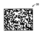
図5を参照して、S12で生成されるランダムドット画像30について説明する。ランダムドット画像30を生成するのに、キーコードと識別子を結合したものを鍵として擬似乱数列発生させている。たとえば、擬似乱数列の数値とランダムドット画像30を構成する画素とを1対1で対応させ、各擬似乱数値を2で割って、その余りが1の場合には対応の画素について点を生成し、余りが0の場合には点を生成しないようにすることにより、図5に示したような各画素について点の出現確率がおよそ50%のランダムドット画像30を生成することができる。ランダムドット画像30のサイズが決まっていれば擬似乱数列とランダムドット画像30は1対1対応しているため、復号時にキーコードと識別子さえ与えれば一意のランダムドット画像30を再生することができる。
【0089】
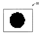
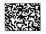
図6、図7および図8を参照して、S13にてCPU10が行う暗号画像31の生成処理を説明する。たとえば図6のような第1のマスク画像32の場合は図5に示したランダムドット画像30と図6に示した第1のマスク画像32を画素ごとに排他的論理和演算を行うことにより図7に示した暗号画像が生成される。
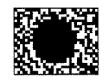
【0090】
図7に示した暗号画像は図5に示したランダムドット画像30と重ね合わせると図8のように図6に示した第1のマスク画像32が出現する。これは数1によって示すことができる。ただし、数1ではランダムドット画像30をK、暗号画像31をE、第1のマスク画像32をMとして表すものとする。
【0091】
【数1】

ランダムドット画像30と暗号画像31を重ね合わせるということはKとEの論理和で表現できる。数1からKとEの論理和はKとMの論理和と等しい。つまり、ランダムドット画像30と第1のマスク画像32を重ね合わせたものと等しいことがわかるため、ランダムドット画像30と暗号画像31を重ね合わせると第1のマスク画像32が出現するということがわかる。また、図7に示した暗号画像をスキャナで読み取り、図5に示したランダムドット画像30と排他的論理和演算することにより図6に示した第1のマスク画像32を完全に復元することもできる。これは数2によって示すことができる。
【0093】
【数2】
数2より、ランダムドット画像30のKと暗号画像31のEの排他的論理和をとると第1のマスク画像32のMと等しくなることがわかる。
【0095】
図9を用いてS15にて実行される幾何学変換について説明する。図9はプリンタにおける両面印刷のメカニズムを矢印で示す紙送り経路と処理段階ST1〜ST3を指示しながら模式的に示したものである。一般に両面印刷を行う場合、一度表面を印刷しながら所定の用紙経路を搬送しながら排紙を行い(ST1)、紙送りローラを介して逆方向に紙送りを行って用紙を反転させ(ST2、ST3)、裏面を印刷するため、表面を印刷する経路と裏面を印刷する経路が異なる。このため、紙送り精度に微妙な差が生じて裏表で紙送り方向のサイズが若干異なることになる。また、印刷のドラムの取り付け精度により印刷面が傾くこともある。さらに、表面と裏面とで印刷を開始するタイミングの違いにより印刷位置がずれることもある。一般的なプリンタではこれらは製造上の誤差として扱われ、ある程度は補正されるが完全には補正されない。このような課題は組合わさって発生するため、表面と裏面において全く同一の場所に印刷される保証はない。
【0096】
ここで裏表の紙送りの差による画像の拡大縮小は線形変換とみなすことができ、画像の変倍、回転、平行移動を組合わせた変換も線形変換である。プリンタの製造上の誤差を打ち消すためにはそれぞれ逆変換を行うことになるが、変倍、回転、平行移動の逆変換もまた変倍、回転、平行移動という線形変換となる。さらに、紙を透過させて見たとき、裏面に印刷するランダムドット画像が表面の暗号画像と同じ位置に見えるためには裏面のランダムドット画像を鏡像変換する必要があるが、鏡像変換も線形変換である。このことからS15では一度の幾何学変換を行うだけで鏡像変換、変倍変換、回転変換、平行移動変換を行うことができる。具体的には、この幾何変換は数3のように行うことができる。
【0097】
【数3】
数3では、変換前の座標をpとし、変換後の座標をp’とし、変換行列をAとし、定数をcとしている。変換行列Aと定数cはプリンタ1の特性に応じてあらかじめ求めておく。これにより、表の暗号画像と裏のランダムドット画像を正確に位置合わせを行って印刷出力することが可能になって、両面印刷によって第1のマスク画像32が視認できるようになる。逆に、通常のプリンタ、複写機では表裏で完全に画像が一致することはないため、両面コピーを行っても第1のマスク画像32が視認できるようにはならず、不正コピーを防止することができる。
【0099】
図10を用いてS16で実行される濃度変換について説明する。紙を透過させて表面から観測する場合、裏面の画像は薄く見える。このため、ランダムドット画像と暗号画像を裏表で同じ濃度で印刷すると透過させてみたときに濃度差が出るため、第1のマスク画像32が目立たなくなる。本実施の形態では、S16において図10に示すように表面に印刷する暗号画像が裏面に印刷するランダムドット画像よりも薄くなるような擬似濃淡パターンに変換する。図示の都合上、斜線で濃淡を表現しているが、擬似濃淡パターンは網点であってもよい。
【0100】
さらに図11を用いてS16で実行される濃度変換による第2のマスク画像33の埋め込みについて説明する。第2のマスク画像33を参照し、ランダムドット画像もしくは暗号画像において、第2のマスク画像33の白画素と対応する点は擬似濃淡パターンAPに変換し、黒画素と対応する点は擬似濃淡パターンBPに変換する。図11の擬似濃淡パターンAPとBPは濃度が同じに見え、擬似パターンAPは細かいパターンで、擬似パターンBPは粗いパターンとして設計されれば、印刷した段階では第2のマスク画像33は視認できず、コピーして初めて第2のマスク画像33が視認できるようになる。
【0101】
(応用例)
図12と図13に本実施の形態に係る応用例を示す。図12では紙面の表面の印刷領域全体において暗号画像が背景画像として印刷されて、裏面においては同様にランダムドット画像が背景画像として印刷されている。図13では、印刷領域全体に暗号画像またはランダムドット画像を印刷するのでなく、一部領域において印刷している。なお、この暗号画像またはランダムドット画像にはさらに何らかの潜像が埋め込まれる(合成される)ようにしてもよい。
【0102】
(実施の形態の効果)
以上のように、本発明の実施の形態によれば、印刷物に第1のマスク画像32を埋め込むことができる。これはキーコードを知らないと復元することはできないし、偽造することもできないため、本物であることの証明になる。同じキーコードを使用し続けると第三者に暗号画像を解読されてしまう危険性があるけれども、さらに、識別子を組合せて利用することでこの危険性を軽減できる。
【0103】
また、ランダムドット画像と暗号画像を両面に印刷することにより、通常の複写機(スキャナ+プリンタ)、プリンタで可視的な透かしを実現することができる。この両面印刷による透かしは正確な位置合わせを行わないと実現できないので、第三者が両面複写機で不正にコピーして透かしを再現することは困難となって、不正コピーを防止できる。
【0104】
さらに、第2のマスク画像33に対応するように擬似濃淡パターンを選択することにより、コピーすると第2のマスク画像33が浮き上がるようすることも可能になる。つまり、コピーしていない本物は透かしとして出現する第1のマスク画像32によって本物であることが見て分かり、コピーすると、第2のマスク画像33が出現することによって複製物(偽造された物)であることが見て分かるといった2つの特徴を同時に実現することが可能になる。
【0105】
今回開示された実施の形態はすべての点で例示であって制限的なものではないと考えられるべきである。本発明の範囲は上記した説明ではなくて、特許請求の範囲によって示され、特許請求の範囲と均等の意味および範囲内でのすべての変更が含まれることが意図される。
【0106】
【発明の効果】
本発明によれば、第1のランダムドット画像に第2のランダムドット画像を重ね合わせたときに、第1のマスク画像を視覚的に出現させることができる第1のランダムドット画像のみを本物(偽造されたものでない)と認証することができる。
【0107】
また、発明によれば、第2のマスク画像が埋め込まれたランダムドット画像の対応する各点については第2のマスク画像に応じて異なる密度でかつ同じ濃度に見えるパターンに変換されているから、該ランダムドット画像を複写機などでコピーすることによって第2のマスク画像を出現させることが可能となる。したがって、第2のマスク画像が出現することで、複写機などでコピーなどした偽物であって本物(複写されていないもの)でないということを識別できる。
【図面の簡単な説明】
【図1】本発明の実施の形態に係る画像出力装置を実現するプリンタの外観図である。
【図2】(A)と(B)は図1に示すプリンタの制御ブロックとメモリ内容例を示す図である。
【図3】本発明の実施の形態に係るコンピュータの構成図である。
【図4】本発明の実施の形態に係る画像出力装置で実行されるプログラムの制御構造を示すフローチャートである。
【図5】ランダムドット画像の例を説明する図である。
【図6】第1のマスク画像の例を説明する図である。
【図7】暗号画像の例を説明する図である。
【図8】暗号画像とランダムドット画像を重ね合わせた例を説明する図である。
【図9】プリンタにおける両面印刷の原理を説明する図である。
【図10】濃度変換を説明する図である。
【図11】第2のマスク画像を埋め込む方法を説明する図である。
【図12】本実施の形態に係る応用例を示す図である。
【図13】本実施の形態に係る応用例を示す図である。
【符号の説明】
1 プリンタ、10 CPU、11 ROM、12 RAM、13 操作パネル、14 外部I/F、15 印刷エンジン、16 バス、30 ランダムドット画像、31 暗号画像、32 第1のマスク画像、33 第2のマスク画像。[0001]
TECHNICAL FIELD OF THE INVENTION
The present invention relates to an image processing apparatus, an image processing method, an image processing program, and a machine-readable recording medium storing the image processing program, and more particularly, to an image processing apparatus, an image processing method, and an image that embed another image in an output image. The present invention relates to a machine-readable recording medium storing a processing program and an image processing program.
[0002]
[Prior art]
The recent development of copier technology has made it possible to easily copy and forge documents, which has become a major social problem. For this reason, there is an image embedding technology as one of the technologies which makes it easy to distinguish a genuine product from a duplicate product and makes it difficult to forge.
[0003]
Traditionally, banknotes are embedded with portraits or pictures of buildings as "watermarks" to prevent counterfeiting, but they require special paper called "made-in paper", so they are applied to general paper and copiers. I couldn't do that. In the method and the printing apparatus for generating a show-through pattern, the first halftone pattern and the second halftone pattern are arranged so as to form markings that can be visually recognized by illumination from the show-through light source. A technique for realizing a watermark in a copying machine has been provided (for example, see Patent Document 1). Since the watermark is realized by locally shifting at least one of the phase, angle, and frequency of the halftone dot of the second halftone pattern, the watermark can be obtained even if accurate alignment is not performed on both sides. Although it can be reproduced, it can be easily duplicated, and the original effect of watermarking and forgery prevention is poor. Further, since the second halftone pattern is locally deformed, there is also a problem that it is easy to visually recognize what kind of watermark is embedded simply by observing the second halftone pattern. Was.
[0004]
As a technique to make an image appear only by superimposing two images, it is not possible to see what is embedded from only one image, and information related to copyright, such as the signature of the image author, is added to the image There is a copying apparatus that embeds an embedding method and copyright information in an image (for example, see Patent Document 2). In this copying apparatus, two pattern cells are prepared in accordance with the luminance level, two different pattern cells are selected for embedding black pixels, and the same pattern cell is selected for embedding white pixels. By creating an image, when the two images are superimposed, the embedded image can be visually recognized.
[0005]
However, in order to verify the embedded image, a pair of verification images created at the time of embedding is required, and there is a problem in storage and delivery of the verification image, and there are problems in safety and convenience. . In addition, since the density pattern cell needs to have a size of at least 2 × 2, there is a problem that the resolution of an image to be embedded is reduced.
[0006]
As a technology that makes it easy to see that a copy is a duplicate when copied, in a latent image printed material suitable for preventing forgery by copying, the latent image portion is printed with fine dots, and the white background portion is printed with coarse dots that look uniform Accordingly, a technology has been proposed in which a latent image is clearly recognized when copied (for example, see Patent Document 3). This utilizes the limit of the reproducibility of a copying machine, and the same technology is applied to copying of a resident's card, and the character "copy" appears when copying.
[0007]
However, the same device and method can be used to produce the same device, and it is difficult to distinguish the device from the genuine product. Therefore, it has been difficult to prevent forgery. In addition, since the image emerges only after copying, it is difficult to recognize at first glance that the image is genuine.
[0008]
[Patent Document 1]
JP-A-2002-142105
[0009]
[Patent Document 2]
Japanese Patent Application Laid-Open No. 9-252397
[0010]
[Patent Document 3]
Japanese Patent Publication No. 55-45400
[0011]
[Problems to be solved by the invention]
Therefore, it is desired to provide a function that is difficult to forge by anyone other than the person and can be easily verified as a genuine article, that it is difficult to create a duplicate, and that it is easy to determine that the original is a duplicate even if it is duplicated. .
[0012]
Therefore, an object of the present invention is to provide an image processing apparatus, an image processing method, an image processing program, and a machine-readable recording medium storing the image processing program, which can easily verify the authenticity.
[0013]
It is another object of the present invention to provide an image processing apparatus, an image processing method, an image processing program, and a machine-readable recording medium that stores the image processing program, which makes it difficult to forge an image.
[0014]
[Means for Solving the Problems]
According to an aspect of the present invention, an image processing apparatus that processes an image to be output includes a first random dot image generating unit that generates a first random dot image in which points are randomly arranged, A second random dot image generating means for generating a second random dot image by performing a predetermined operation for each pixel corresponding to one random dot image and a first mask image prepared in advance; The predetermined calculation is performed when the generated first random dot image and the second random dot image are superimposed on each other so that the pixels are coincident with each other and are output, via the first random dot image. This is an operation for visually appearing a mask image.
[0015]
Therefore, only the person or device having (can generate) the first random dot image used when generating the second random dot image has the second random dot image received from the other party (generating). By performing an operation opposite to the predetermined operation with respect to the first random dot image, the first mask image can be restored, so that encrypted communication using the first mask image as secret information becomes possible. Also, if the first random dot image that is held (generated) is printed on a transparent sheet and the second random dot image received from the other party is overlaid, the above-described inverse operation is performed. Since the first mask image can be restored, encrypted communication using the first mask image as secret information becomes possible.
[0016]
As described above, when the second random dot image is superimposed on the first random dot image, only the first random dot image that allows the first mask image to appear visually is authentic (forged). Can not be authenticated).
[0017]
In addition, since the overlapping of the two requires that the corresponding pixels match, it is possible to make it difficult to duplicate the output product and prevent forgery.
[0018]
In addition, the second random dot image for visually appearing the first mask image via the first random dot image is generated using the first random dot image generated each time. And forgery can be more reliably prevented. Also, since the second random dot image is generated using the first random dot image, it is not necessary to store the second random dot image.
[0019]
Preferably, the image processing apparatus further includes a superimposition processing unit that processes the generated first random dot image and the second random dot image so that when the two are superimposed and output, the corresponding pixels coincide.
[0020]
Preferably, since the above-mentioned predetermined operation is an exclusive OR operation, the first mask image can be embedded in the second random dot image by a simple operation for visual appearance. In this case, the reverse operation described above is a logical sum operation.
[0021]
Further, if the second random dot image is read by a scanner or the like and exclusive OR operation is performed with the first random dot image, the first mask image can be completely restored.
[0022]
Preferably, the first random dot image generating means generates the first random dot image such that the appearance probability of a point becomes approximately 50%.
[0023]
Therefore, even in the generated second random dot image, the appearance probability of the points is also approximately 50%, so that only the dots appear to be arranged randomly, and are embedded in the second random dot image. It is possible to hide the first mask image from a third party.
[0024]
Preferably, the first random dot image generation means generates the first random dot image according to a random number sequence uniquely determined using the key data, so that the first random dot image can be easily generated and the key data is By concealing from the third party, forgery of the first random dot image can be prevented. Since the first random dot image can be generated by using the key data, it is not necessary to store the first random dot image. Also, in the case where the second random dot image is transferred, the first mask image can be restored by transferring the key data.
[0025]
In addition, a third party who does not know the key code cannot decrypt the second random dot image, and cannot forge the same. Since only the person who knows the key data can restore the first mask image, it can be easily verified that the second random dot image is genuine, and it is difficult to forge the second random dot image.
[0026]
Preferably, the key data includes a different identifier generated each time an image is output. If the same key data is continuously used, the key data does not need to be changed, so that the convenience is high, but the encryption strength generally decreases. Therefore, by including an identifier in the key data, a different first random dot image is generated if the identifier is different, so that the encryption strength is not impaired.
[0027]
Preferably, the image processing apparatus further includes a data input unit that inputs key data from outside. Therefore, the key data can be arbitrarily changed from the outside, and a decrease in encryption strength can be suppressed.
[0028]
Preferably, the identifier is output together with the second random dot image. Therefore, even if a second random dot image is generated using a different first random dot image for each image output, the identifier included in the key data is output together with the second random dot image. Since random dots can be reproduced by using the given identifier, there is no problem in decoding the second random dot image.
[0029]
Preferably, each point of at least one of the first random dot image and the second random dot image looks at a different density and the same density according to the second mask image prepared in advance. An image embedding unit is provided for performing a process of embedding the second mask image in at least one of the first and second random dot images by converting the image into a pattern.
[0030]
Therefore, two images of the first mask image and the second mask image can be embedded in the random dot image. The first mask image appears when the first and second random dot images are superimposed, and each corresponding point of the random dot image in which the second mask image is embedded is different depending on the second mask image. Since the pattern is converted into a pattern having the same density and the same density, the second mask image can be made to appear by copying the random dot image with a copying machine or the like. Therefore, the appearance of the second mask image makes it possible to identify that the image is a fake copied by a copying machine or the like and not a genuine one (not copied).
[0031]
Preferably, when printing an image on paper, the first random dot image is printed out on one side of the paper and the second random dot image is printed out on the other side of the same paper.
[0032]
Therefore, since the first random dot image is printed on one side of the printing surface of the paper and the second random dot image is printed on the other side, the first mask image appears by holding the printed matter (paper) over the light source. It is possible to do.
[0033]
Preferably, the superposition processing means has a mirror image conversion means for converting one of the first random dot image and the second random dot image into a mirror image with respect to the other, so that the superposition is performed accurately. be able to.
[0034]
Preferably, the superposition processing means performs image conversion means for performing at least one of parallel translation conversion, rotation conversion, and scaling conversion on at least one of the first random dot image and the second random dot image. Having.
[0035]
Therefore, the image is output after correcting the positional deviation at the time of double-sided printing on the paper in advance, and printing can be performed at a more accurate overlapping position. Therefore, the first mask image (watermark) can clearly appear.
[0036]
Generally, a copier capable of printing on both sides prints the first and second random dot images on both sides of the sheet because the printing positions of the front and rear sides do not completely match due to the paper feeding accuracy of the sheet and the mounting accuracy of the printing drum. It is difficult for a user to reproduce the same watermark even if both sides are copied. Therefore, whether or not the first mask image (watermark) has been forged can be quickly determined based on whether or not the first mask image (watermark) appears, and forgery can be suppressed.
[0037]
Preferably, the image processing device further includes a density of at least one of the random dot images such that an image density of the first random dot image and a density of the second random dot image are different depending on the transmittance of the printing surface of the sheet. Image density conversion means for converting the image density.
[0038]
Therefore, by making the density of the random dot image on the side where the watermark (first mask image) is observed lighter than that of the random dot image in which the watermark is embedded, the density of the random dot image on the side where the watermark is embedded becomes transparent. The density can be made equal to the density of the random dot image on the back side (the side opposite to the observation side) that can be seen, so that the watermark can be more clearly observed.
[0039]
According to another aspect of the present invention, an image processing method for processing an image to be output includes a first random dot image generating step of generating a first random dot image in which dots are randomly arranged; A second random dot image generating step of generating a second random dot image by performing a predetermined operation for each pixel corresponding to the first random dot image and the first mask image prepared in advance. The predetermined calculation is performed when the generated first random dot image and the second random dot image are superimposed on each other so that the pixels are coincident with each other and are output, via the first random dot image. Is an operation for visually appearing the mask image of.
[0040]
Therefore, only the person or device having (can generate) the first random dot image used when generating the second random dot image has the second random dot image received from the other party (generating). By performing an operation opposite to the predetermined operation with respect to the first random dot image, the first mask image can be restored, so that encrypted communication using the first mask image as secret information becomes possible. Also, if the first random dot image that is possessed (generated) is printed on a transparent sheet and the second random dot image received from the other party is superimposed, the above inverse operation has been performed. Since the first mask image can be restored, encrypted communication using the first mask image as secret information becomes possible.
[0041]
As described above, when the second random dot image is superimposed on the first random dot image, only the first random dot image that allows the first mask image to appear visually is authentic (forged). Can not be authenticated).
[0042]
In addition, since the overlapping of the two requires that the corresponding pixels match, it is possible to make it difficult to duplicate the output product and prevent forgery.
[0043]
In addition, the second random dot image for visually appearing the first mask image via the first random dot image is generated using the first random dot image generated each time. And forgery can be more reliably prevented. Also, since the second random dot image is generated using the first random dot image, it is not necessary to store the second random dot image.
[0044]
Preferably, the method further includes a superposition processing step of processing the generated first random dot image and the second random dot image so that when the two are superimposed and output, the corresponding pixels coincide.
[0045]
Preferably, the predetermined operation is an exclusive OR operation.
Preferably, in the first random dot image generation step, the first random dot image is generated such that the probability of appearance of a point becomes approximately 50%.
[0046]
Preferably, the first random dot image generating step generates the first random dot image according to a random number sequence uniquely determined using the key data.
[0047]
Preferably, the key data includes a different identifier generated each time an image is output.
[0048]
Preferably, the image processing apparatus further includes a data input step of externally inputting the key data.
[0049]
Preferably, the identifier is output together with the second random dot image.
Preferably, each point of at least one of the first random dot image and the second random dot image looks at a different density and the same density according to the second mask image prepared in advance. An image embedding step of embedding a second mask image in at least one of the first and second random dot images by converting the image into a pattern is provided.
[0050]
Preferably, when printing an image on paper, the first random dot image is printed out on one side of the paper and the second random dot image is printed out on the other side of the same paper.
[0051]
Preferably, the superimposition processing step includes a mirror image conversion step of converting one of the first random dot image and the second random dot image into a mirror image with respect to the other.
[0052]
Preferably, the superimposition processing step is an image conversion step of performing at least one of parallel translation conversion, rotation conversion, and scaling conversion on at least one of the first random dot image and the second random dot image. Having.
[0053]
Preferably, the image processing method further includes the step of changing the density of at least one of the random dot images so that the image density of the first random dot image and the image density of the second random dot image are different depending on the transmittance of the printing surface of the sheet. And an image density conversion step of performing a conversion process.
[0054]
An image processing program according to still another aspect of the present invention is a program for causing a computer to execute the above-described image processing method.
[0055]
A machine-readable recording medium according to still another aspect of the present invention is a recording medium recording the above-described image processing program.
[0056]
BEST MODE FOR CARRYING OUT THE INVENTION
Hereinafter, embodiments of the present invention will be described with reference to the drawings. In the following description, the same components are denoted by the same reference numerals. Their names and functions are the same. Therefore, detailed description thereof will not be repeated.
[0057]
Processing in the image output apparatus according to the present embodiment is realized by software executed by an image processing control engine such as a printer or a copier having both a printer function and a scanner function. It may be realized by printer driver software executed on a personal computer or a workstation, or may be realized as dedicated hardware. Further, the printer may be a device including a scanner unit like a general copying machine.
[0058]
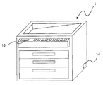
FIG. 1 shows the appearance of a printer 1 as an example of an image output device. Referring to FIG. 1, a printer 1 is realized by an
[0059]
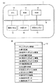
FIG. 2A shows a configuration of the printer 1 in a block diagram format. The printer 1 includes, in addition to an
[0060]
The
[0061]
As described above, the image output device according to the present embodiment is realized by the hardware of the printer 1 and the software executed by the
[0062]
The case where the image output processing according to the present embodiment is realized by printer driver software executed on a personal computer or a workstation is as follows. FIG. 3 is a configuration diagram of a computer having an image output processing function according to the present embodiment.
[0063]
Referring to FIG. 3, a computer includes a
[0064]
Output information (image) as a result of execution of the printer driver software of the computer in FIG. 3 is printed by a printer (not shown). The printer may be connected to a computer on a communication network 182 via a
[0065]
The printer driver software is stored on a computer-readable recording medium. In the present embodiment, the recording medium may be a program medium such as a memory required for performing the processing in FIG. 3, for example, a ROM itself of the
[0066]
Here, the above-described program medium is a recording medium configured to be separable from the computer main body, and may be a medium that holds a fixed program. For example, a tape system such as a magnetic tape and a cassette tape, a magnetic disk such as the
[0067]
Further, in the present embodiment, since the computer is configured to be connectable to the communication network 182 including the Internet via the
[0068]
The content stored in the recording medium is not limited to a program, but may be data.
[0069]
The printer 1 and the workstation shown in FIGS. 1 and 2 and the hardware itself of the computer shown in FIG. 3 are common. Therefore, the most essential part of the present invention is software recorded on a recording medium such as the CD-
[0070]
Note that detailed description of well-known operations of the printer 1 itself shown in FIGS. 1 and 2 will not be repeated.
[0071]
With reference to the flowchart of FIG. 4, a procedure executed by the image output device according to the present embodiment will be described. First, since the user inputs a key code using the
[0072]
When the image output apparatus according to the present embodiment is realized by printer driver software, the
[0073]
In S11,
[0074]
In S12,
[0075]
Since the algorithm for generating the pseudo-random number sequence is well known, its description is omitted. Preferably, the
[0076]
In S13, the
[0077]
In S14, the
[0078]
In S15, the
[0079]
The geometric transformation may be performed on the scaled encrypted image 31H, or at least one of the scaled random dot image 30H and the scaled encrypted image 31H.
[0080]
The geometric transformation may include a linear transformation to be described later. In this case, the mirror image transformation, the parallel movement transformation, the rotation transformation, and the scaling transformation can be performed in a single transformation.
[0081]
If only the encrypted image is printed without performing double-sided printing, S15 may be omitted. Here, printing only the encrypted image means that only the person or device having (reproducible) the random dot image used to generate the encrypted image can restore the
[0082]
In S16, the
[0083]
At this time, according to the transmittance of the printing surface, for example, a pseudo shade pattern is selected and the density is converted so that the encrypted image is lighter. Accordingly, when the encrypted image is observed from the side on which the image is printed, the density becomes close to the density of the transmitted random dot image, and the watermark (first mask image) can be visually recognized more clearly.
[0084]
Further, the
[0085]
In S17,
[0086]
In S18, the
[0087]
In S19, the
[0088]
The
[0089]
With reference to FIG. 6, FIG. 7, and FIG. 8, the process of generating the encrypted image 31 performed by the
[0090]
When the encrypted image shown in FIG. 7 is superimposed on the
[0091]
(Equation 1)
The superposition of the
[0093]
(Equation 2)
From Expression 2, it is understood that the exclusive OR of K of the
[0095]
The geometric transformation performed in S15 will be described with reference to FIG. FIG. 9 schematically shows the mechanism of double-sided printing in the printer while indicating a paper feed path indicated by an arrow and processing steps ST1 to ST3. In general, when performing double-sided printing, paper is discharged while transporting a predetermined paper path while printing the front surface once (ST1), and paper is fed in the reverse direction via a paper feed roller to invert the paper (ST2, ST3) Since the back side is printed, the path for printing the front side is different from the path for printing the back side. For this reason, a slight difference occurs in the paper feeding accuracy, and the size in the paper feeding direction is slightly different between the front and the back. Further, the printing surface may be inclined depending on the mounting accuracy of the printing drum. Further, the printing position may be shifted due to the difference in the timing of starting printing on the front surface and the back surface. In a general printer, these are treated as manufacturing errors, and are corrected to some extent but not completely. Since such problems occur in combination, there is no guarantee that printing is performed at exactly the same location on the front and back surfaces.
[0096]
Here, the enlargement / reduction of the image due to the difference in paper feed between the front and the back can be regarded as linear conversion, and the conversion combining the scaling, rotation, and parallel movement of the image is also linear conversion. In order to cancel the errors in the manufacture of the printer, inverse transformations are performed, respectively, but the inverse transformations of scaling, rotation, and translation are also linear transformations such as scaling, rotation, and translation. Furthermore, when seeing through the paper, the random dot image to be printed on the back side needs to be mirror-converted for the random dot image on the back side to appear at the same position as the encrypted image on the front side. It is. Thus, in S15, mirror image conversion, scaling conversion, rotation conversion, and translation conversion can be performed by performing only one geometrical conversion. Specifically, this geometric transformation can be performed as in
[0097]
[Equation 3]
In
[0099]
The density conversion performed in S16 will be described with reference to FIG. When observed from the front side through paper, the image on the back side looks faint. For this reason, if the random dot image and the encrypted image are printed at the same density on the front and back sides, a density difference will occur when transmitted, so that the
[0100]
Further, the embedding of the
[0101]
(Application example)
12 and 13 show application examples according to the present embodiment. In FIG. 12, the encrypted image is printed as a background image over the entire print area on the front surface of the paper, and a random dot image is similarly printed as a background image on the back surface. In FIG. 13, the encrypted image or the random dot image is not printed on the entire print area, but is printed on a partial area. Note that a certain latent image may be further embedded (combined) in the encrypted image or the random dot image.
[0102]
(Effects of Embodiment)
As described above, according to the embodiment of the present invention, the
[0103]
Further, by printing the random dot image and the encrypted image on both sides, a visible watermark can be realized by a normal copying machine (scanner + printer) or printer. Since the watermark by double-sided printing cannot be realized without accurate alignment, it is difficult for a third party to illegally copy and reproduce the watermark with a double-sided copying machine, thereby preventing illegal copying.
[0104]
Furthermore, by selecting a pseudo shade pattern so as to correspond to the
[0105]
The embodiments disclosed this time are to be considered in all respects as illustrative and not restrictive. The scope of the present invention is defined by the terms of the claims, rather than the description above, and is intended to include any modifications within the scope and meaning equivalent to the terms of the claims.
[0106]
【The invention's effect】
According to the present invention, when the first random dot image is superimposed on the second random dot image, only the first random dot image that allows the first mask image to appear visually is used as the real ( Not forged).
[0107]
According to the invention, each corresponding point of the random dot image in which the second mask image is embedded is converted into a pattern having a different density and the same density according to the second mask image. By copying the random dot image with a copying machine or the like, the second mask image can appear. Therefore, the appearance of the second mask image makes it possible to identify that the image is a fake copied by a copying machine or the like and not a genuine one (not copied).
[Brief description of the drawings]
FIG. 1 is an external view of a printer that realizes an image output device according to an embodiment of the present invention.
FIGS. 2A and 2B are diagrams showing control blocks and memory contents of the printer shown in FIG.
FIG. 3 is a configuration diagram of a computer according to the embodiment of the present invention.
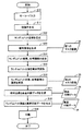
FIG. 4 is a flowchart illustrating a control structure of a program executed by the image output device according to the embodiment of the present invention.
FIG. 5 is a diagram illustrating an example of a random dot image.
FIG. 6 is a diagram illustrating an example of a first mask image.
FIG. 7 is a diagram illustrating an example of an encrypted image.
FIG. 8 is a diagram illustrating an example in which an encrypted image and a random dot image are superimposed.
FIG. 9 is a diagram illustrating the principle of double-sided printing in a printer.
FIG. 10 is a diagram illustrating density conversion.
FIG. 11 is a diagram illustrating a method of embedding a second mask image.
FIG. 12 is a diagram showing an application example according to the present embodiment.
FIG. 13 is a diagram showing an application example according to the present embodiment.
[Explanation of symbols]
1 printer, 10 CPU, 11 ROM, 12 RAM, 13 operation panel, 14 external I / F, 15 print engine, 16 bus, 30 random dot image, 31 encrypted image, 32 first mask image, 33 second mask image.
Claims (15)
点がランダムに配置される第1のランダムドット画像を生成する第1のランダムドット画像生成手段と、
生成された前記第1のランダムドット画像と予め準備された第1のマスク画像との対応する画素ごとに所定の演算を行うことにより第2のランダムドット画像を生成する第2のランダムドット画像生成手段とを備えて、
前記所定演算は、生成された前記第1のランダムドット画像と前記第2のランダムドット画像とが画素どうしが一致するよう重ね合わせられて出力されるとき、前記第1のランダムドット画像を介して前記第1のマスク画像を視覚的に出現させるための演算であることを特徴とする、画像処理装置。An image processing apparatus for processing an image to be output,
First random dot image generating means for generating a first random dot image in which points are randomly arranged;
A second random dot image generation for generating a second random dot image by performing a predetermined operation for each corresponding pixel between the generated first random dot image and a previously prepared first mask image With means,
The predetermined operation is performed through the first random dot image when the generated first random dot image and the second random dot image are output so as to be overlapped with each other so that the pixels match. An image processing apparatus, which is an operation for visually appearing the first mask image.
点がランダムに配置される第1のランダムドット画像を生成する第1のランダムドット画像生成ステップと、
生成された前記第1のランダムドット画像と予め準備された第1のマスク画像との対応する画素ごとに所定の演算を行うことにより第2のランダムドット画像を生成する第2のランダムドット画像生成ステップとを備えて、
前記所定演算は、生成された前記第1のランダムドット画像と前記第2のランダムドット画像とが画素どうしが一致するよう重ね合わせられて出力されるとき、前記第1のランダムドット画像を介して前記第1のマスク画像を視覚的に出現させるための演算であることを特徴とす、画像処理方法。An image processing method for processing an image to be output, comprising:
A first random dot image generating step of generating a first random dot image in which points are randomly arranged;
A second random dot image generation for generating a second random dot image by performing a predetermined operation for each corresponding pixel between the generated first random dot image and a previously prepared first mask image With steps
The predetermined operation is performed through the first random dot image when the generated first random dot image and the second random dot image are output so as to be overlapped with each other so that the pixels match. An image processing method, characterized in that the calculation is an operation for visually appearing the first mask image.
Priority Applications (2)
| Application Number | Priority Date | Filing Date | Title |
|---|---|---|---|
| JP2003131660A JP2004336539A (en) | 2003-05-09 | 2003-05-09 | Image processor, image processing method, image processing program, and mechanically readable recording medium having image processing program recorded therein |
| PCT/JP2004/005586 WO2004100527A1 (en) | 2003-05-09 | 2004-04-19 | Image processing device, image processing method, image processing program, and mechanically readable recordoing medium containing the image processing program |
Applications Claiming Priority (1)
| Application Number | Priority Date | Filing Date | Title |
|---|---|---|---|
| JP2003131660A JP2004336539A (en) | 2003-05-09 | 2003-05-09 | Image processor, image processing method, image processing program, and mechanically readable recording medium having image processing program recorded therein |
Publications (1)
| Publication Number | Publication Date |
|---|---|
| JP2004336539A true JP2004336539A (en) | 2004-11-25 |
Family
ID=33432137
Family Applications (1)
| Application Number | Title | Priority Date | Filing Date |
|---|---|---|---|
| JP2003131660A Pending JP2004336539A (en) | 2003-05-09 | 2003-05-09 | Image processor, image processing method, image processing program, and mechanically readable recording medium having image processing program recorded therein |
Country Status (2)
| Country | Link |
|---|---|
| JP (1) | JP2004336539A (en) |
| WO (1) | WO2004100527A1 (en) |
Cited By (2)
| Publication number | Priority date | Publication date | Assignee | Title |
|---|---|---|---|---|
| JP2009111980A (en) * | 2007-09-10 | 2009-05-21 | Konica Minolta Systems Lab Inc | Determining document authenticity in closed-loop process |
| JP2010182039A (en) * | 2009-02-04 | 2010-08-19 | Canon Inc | Layout device, layout method, and layout program |
Families Citing this family (1)
| Publication number | Priority date | Publication date | Assignee | Title |
|---|---|---|---|---|
| JP4137933B2 (en) * | 2005-10-31 | 2008-08-20 | シャープ株式会社 | Image processing apparatus, program, and recording medium |
Family Cites Families (5)
| Publication number | Priority date | Publication date | Assignee | Title |
|---|---|---|---|---|
| JPH0813568B2 (en) * | 1991-11-22 | 1996-02-14 | 大蔵省印刷局長 | Laminated image front and back pattern synthetic printed material and method for producing the same |
| JP3362171B2 (en) * | 1993-07-12 | 2003-01-07 | 財務省印刷局長 | Front and back pattern composite printed matter in which a latent image appears as a color image and method for producing the same |
| GB2282563A (en) * | 1993-10-07 | 1995-04-12 | Central Research Lab Ltd | A composite image arrangement for documents of value |
| JP3482251B2 (en) * | 1994-07-29 | 2003-12-22 | トッパン・フォームズ株式会社 | Printed copy to prevent copy forgery |
| JP2001118122A (en) * | 1999-10-22 | 2001-04-27 | Toppan Printing Co Ltd | Recording medium utilizing visual decoding type cryptography |
-
2003
- 2003-05-09 JP JP2003131660A patent/JP2004336539A/en active Pending
-
2004
- 2004-04-19 WO PCT/JP2004/005586 patent/WO2004100527A1/en active Application Filing
Cited By (4)
| Publication number | Priority date | Publication date | Assignee | Title |
|---|---|---|---|---|
| JP2009111980A (en) * | 2007-09-10 | 2009-05-21 | Konica Minolta Systems Lab Inc | Determining document authenticity in closed-loop process |
| US8170275B2 (en) | 2007-09-10 | 2012-05-01 | Konica Minolta Laboratory U.S.A., Inc. | Determining document authenticity in a closed-loop process |
| JP2010182039A (en) * | 2009-02-04 | 2010-08-19 | Canon Inc | Layout device, layout method, and layout program |
| US8954843B2 (en) | 2009-02-04 | 2015-02-10 | Canon Kabushiki Kaisha | Layout apparatus, layout method, and layout program |
Also Published As
| Publication number | Publication date |
|---|---|
| WO2004100527A1 (en) | 2004-11-18 |
Similar Documents
| Publication | Publication Date | Title |
|---|---|---|
| RU2176823C2 (en) | Program-implemented method and device for counterfeiting protection | |
| JP4495824B2 (en) | Information processing method | |
| US6731409B2 (en) | System and method for generating color digital watermarks using conjugate halftone screens | |
| TWI298231B (en) | ||
| EP1048168B1 (en) | Anti-counterfeiting method and apparatus using digital screening | |
| JP3952958B2 (en) | Image processing apparatus and image processing method | |
| ES2622490T3 (en) | Security Image Printing | |
| EP1591953A1 (en) | System and method for decoding digital encoded images | |
| JP2003242347A (en) | Method and apparatus for embedding encrypted image of signature and other data on check | |
| JP2003530737A (en) | Optical watermark | |
| WO2007057363A1 (en) | Marking images of text with speckle patterns | |
| JP5138904B2 (en) | Method and system for providing document security | |
| US8282015B2 (en) | Document with linked viewer file for correlated printing | |
| JP4290681B2 (en) | Image processing apparatus, image processing method, image processing program, machine-readable recording medium recording image processing program, and printed matter | |
| US7283261B2 (en) | Image processing method, manipulation detection method, image processing device, manipulation detection device, image processing program, manipulation detection program, and image formation medium | |
| US9579915B2 (en) | Security image printing | |
| JP2004336539A (en) | Image processor, image processing method, image processing program, and mechanically readable recording medium having image processing program recorded therein | |
| JP3993845B2 (en) | Image processing apparatus, image processing method, and image processing program | |
| CN106708449A (en) | Anti copy method based on negative color image watermark in monochrome printing | |
| US8774450B2 (en) | Unauthorized text alteration prevention with contour following background patterns | |
| JP2001344557A (en) | Method and device for managing document | |
| JP2003152979A (en) | Apparatus and method for printing document | |
| JP2006128852A (en) | Document creation method and device | |
| TW200406717A (en) | Watermarking | |
| JP3988598B2 (en) | Image processing apparatus and image processing program |
Legal Events
| Date | Code | Title | Description |
|---|---|---|---|
| A621 | Written request for application examination |
Free format text: JAPANESE INTERMEDIATE CODE: A621 Effective date: 20050810 |
|
| A131 | Notification of reasons for refusal |
Free format text: JAPANESE INTERMEDIATE CODE: A131 Effective date: 20070703 |
|
| A521 | Request for written amendment filed |
Free format text: JAPANESE INTERMEDIATE CODE: A523 Effective date: 20070831 |
|
| A02 | Decision of refusal |
Free format text: JAPANESE INTERMEDIATE CODE: A02 Effective date: 20080226 |
|
| A521 | Request for written amendment filed |
Free format text: JAPANESE INTERMEDIATE CODE: A523 Effective date: 20080326 |
|
| A911 | Transfer to examiner for re-examination before appeal (zenchi) |
Free format text: JAPANESE INTERMEDIATE CODE: A911 Effective date: 20080509 |
|
| A912 | Re-examination (zenchi) completed and case transferred to appeal board |
Free format text: JAPANESE INTERMEDIATE CODE: A912 Effective date: 20080530 |