JP2004334682A - Data transmission system determination method and transmission line monitoring device between noncontact ic card and reader/writer - Google Patents
Data transmission system determination method and transmission line monitoring device between noncontact ic card and reader/writer Download PDFInfo
- Publication number
- JP2004334682A JP2004334682A JP2003131754A JP2003131754A JP2004334682A JP 2004334682 A JP2004334682 A JP 2004334682A JP 2003131754 A JP2003131754 A JP 2003131754A JP 2003131754 A JP2003131754 A JP 2003131754A JP 2004334682 A JP2004334682 A JP 2004334682A
- Authority
- JP
- Japan
- Prior art keywords
- signal
- value
- feature point
- data transmission
- transmission method
- Prior art date
- Legal status (The legal status is an assumption and is not a legal conclusion. Google has not performed a legal analysis and makes no representation as to the accuracy of the status listed.)
- Granted
Links
- 238000000034 method Methods 0.000 title claims abstract description 273
- 230000005540 biological transmission Effects 0.000 title claims abstract description 248
- 238000012806 monitoring device Methods 0.000 title claims abstract description 35
- 238000000605 extraction Methods 0.000 claims abstract description 105
- 230000008569 process Effects 0.000 claims description 40
- 238000012545 processing Methods 0.000 claims description 30
- 238000004891 communication Methods 0.000 claims description 20
- 238000005259 measurement Methods 0.000 claims description 18
- 238000005070 sampling Methods 0.000 claims description 9
- 238000012544 monitoring process Methods 0.000 claims description 6
- 238000002360 preparation method Methods 0.000 claims 2
- 238000010586 diagram Methods 0.000 description 19
- 230000006870 function Effects 0.000 description 11
- 230000003321 amplification Effects 0.000 description 7
- 238000003199 nucleic acid amplification method Methods 0.000 description 7
- 230000008859 change Effects 0.000 description 5
- 238000001914 filtration Methods 0.000 description 5
- 239000000284 extract Substances 0.000 description 4
- 238000007796 conventional method Methods 0.000 description 3
- 238000012850 discrimination method Methods 0.000 description 3
- 230000004044 response Effects 0.000 description 3
- 238000006243 chemical reaction Methods 0.000 description 2
- 238000001514 detection method Methods 0.000 description 2
- 238000004458 analytical method Methods 0.000 description 1
- 238000004364 calculation method Methods 0.000 description 1
- 239000000969 carrier Substances 0.000 description 1
- 238000012790 confirmation Methods 0.000 description 1
- 125000004122 cyclic group Chemical group 0.000 description 1
- 230000007423 decrease Effects 0.000 description 1
- 239000003550 marker Substances 0.000 description 1
- 230000008520 organization Effects 0.000 description 1
- 230000008054 signal transmission Effects 0.000 description 1
Images


Landscapes
- Near-Field Transmission Systems (AREA)
Abstract
Description
【0001】
【発明の属する技術分野】
本発明は、非接触ICカードとリーダライタ間において、複数のデータ伝送方式で通信が為されている場合に、伝送路を流れる信号を取得し、その信号を用いてデータ伝送方式を判別する非接触ICカード/リーダライタ間のデータ伝送方式判別方法及び伝送路モニタ装置に関するものである。
【0002】
【従来の技術】
近年、非接触ICカードとリーダライタ間のデータ伝送方式として、複数の方式が提案され、標準化されてきている。また、このような複数のデータ伝送方式による通信に対応した非接触ICカードも開発されてきている。
【0003】
しかし、非接触ICカードシステムを開発する場合においては、システムのデバッグ等のため、非接触ICカードとリーダライタ間の伝送路を流れる通信信号をモニタする必要があるが、この場合は、予め決められたデータ伝送方式を指定した上でモニタする必要があり、指定されていないデータ伝送方式で通信が行われた場合には、指定を切り替えてモニタする必要があった。
【0004】
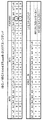
以下に、非接触ICカードシステムにおける、データ伝送方式を判別する従来の方式を説明しておく。まず、伝送路から読み取った信号をデコードし可読情報としてから、通信内容の伝送方式について記載してある位置を参照し、データ伝送方式を判別する方法である。図22、図23にISO/IEC14443(International Organization Standardization/International Electrotechnical Commission 14443)で規定されている非接触ICカードの通信規約に基いたTypeA、TypeBのリーダライタ側からのリクエストコマンドの一例を示す。以下、先ず、この図に付き説明する。
【0005】
図22は、ISO/IEC14443で規格されているTypeAのリーダライタからのリクエストコマンドを示している。本図において、SはTypeAの非接触ICカードにおけるブロック先頭ビット、b1〜b7はデータビット、EはTypeAの非接触ICカードにおけるブロック終了ビットである。REQAはTypeAのリーダライタからのリクエストコマンドであり、図22には、ビットコリジョンとタイムスロットとがコマンドとして例示されている。
【0006】
図23は、TypeBのリーダライタからのリクエストコマンドを示している。本図において、ApfはTypeBのリーダライタからのリクエストコマンドであるREQBで使用されるパラメータであり、AFIは応用分野識別子、PARAMは属性情報のパラメータ、CRC_Bは巡回冗長検査符号Bである。b1〜b7及びb8はデータビットである。REQBは前述の通り、TypeBのリーダライタからのリクエストコマンドであり、本図では、スロットマーカーとタイムスロットとがコマンドとして例示されている。
【0007】
データ伝送方式が異なる場合には、図22、図23をみればわかるとおり、通信を開始する前にリーダライタから発信される非接触ICカードへのリクエストコマンドが異なる。このとき、TypeA、TypeBのそれぞれの非接触ICカードは各々に対応するリクエストコマンドのみにレスポンスを返すため、これによりデータ伝送方式を判別することは可能であった。
【0008】
また、データ伝送方式が同じでも、アンチコリジョンの方式が異なる場合には、図22、図23の○で囲った部分を見ればわかるとおり、リクエストコマンドのパラメータが異なるので、受信したコマンドの内容が自己の目的のものとなっているかどうかに付いては判別することは可能であった。
【0009】
以下に、これら従来技術につき参考となる文献情報を列挙しておく。
【非特許文献】
“JICSAP ICカード仕様V2.0 第2部近接型ICカード”、[online]、[2003年4月21日検索]、インターネット <URL:http://www.jicsap.com/stdwork/kinsetsu.pdf>
【0010】
【発明が解決しようとする課題】
しかしながら、上述した従来方式では、非接触ICカードとリーダライタ間のデータ伝送方式が不明な場合には、伝送路を流れる信号を符号化できないため、モニタができなかった。したがって、特に複数のデータ伝送方式に対応した非接触ICカードをモニタしようとした場合には、データ伝送方式が特定できず、特に顕著な問題となっていた。
【0011】
ここにおいて、本発明の解決すべき主要な目的は以下の通りである。
即ち、本発明の第1の目的は、複数のデータ伝送方式で通信が可能である非接触ICカードとリーダライタ間の信号を取得し、その信号波形を解析することによりデータ伝送方式を判別する非接触ICカード/リーダライタ間のデータ伝送方式判別方法及び伝送路モニタ装置を提供せんとするものである。
【0012】
本発明の第2の目的は、通信が行われている最中であっても、データ伝送方式を判別することを可能とする非接触ICカード/リーダライタ間の伝送方式判別方法及び伝送路モニタ装置を提供せんとするものである。
【0013】
本発明の第3の目的は、読み取った信号をデコードすることなく、信号データそのものを解析することからデータ伝送方式を判別するため、非常に高速に判別を行うことを可能とする非接触ICカード/リーダライタ間の伝送方式判別方法及び伝送路モニタ装置を提供せんとするものである。
【0014】
本発明の第4の目的は、判別したいデータ伝送方式を特に指定することにより、その指定の範囲内のみで判別することを可能とする非接触ICカード/リーダライタ間の伝送方式判別方法及び伝送路モニタ装置を提供せんとするものである。
【0015】
本発明の他の目的は、明細書、図面、特に特許請求の範囲の各請求項の記載から自ずと明らかとなろう。
【0016】
【課題を解決するための手段】
本発明方法は、上記課題の解決に当たり、非接触ICカードとリーダライタ間の伝送路を流れる信号からデータ伝送方式を判別する方法であって、先ず、前記非接触ICカードと前記リーダライタ間の前記伝送路を流れる信号を取得し、次に、当該取得した信号の波形の電圧値を用いて2値化処理し、引続き、当該2値化された信号データから前記データ伝送方式を判別する際の特徴となりうる特徴点の抽出開始位置を検出し、その上で、当該特徴点の抽出開始位置を起点として、予め記憶されている特徴点を抽出するタイミングが記述された特徴点抽出タイミング情報にしたがって前記特徴点の信号値を抽出し、特徴点群を形成していき、最終的に、当該特徴点群の値が、予め記憶されている複数の前記データ伝送方式に特有の信号値が記述されたデータ伝送方式判別条件情報と比較して、データ伝送方式を判別するという手法を講じる。
【0017】
本発明装置は、上記課題の解決に当たり、非接触ICカードとリーダライタ間の伝送路を流れる信号からデータ伝送方式を判別する伝送路モニタ装置であって、前記伝送路を流れる信号を取得し、当該信号を2値化し、2値化された信号データとして出力する電圧取得手段と、当該電圧取得手段からの2値化された信号データから前記データ伝送方式を判別する際の特徴となり得る特徴点の抽出開始位置を特定する特徴点抽出開始位置特定手段と、前記特徴点を抽出するタイミングが記述された特徴点抽出タイミング情報が記憶されている特徴点抽出タイミング情報記憶手段と、前記2値化された信号データから前記特徴点抽出タイミング情報に従って、特徴点の値を抽出し、特徴点群を形成していく特徴点抽出手段と、複数の前記データ伝送方式に特有の信号値が記述されたデータ伝送方式判別条件情報が記憶されているデータ伝送方式判別条件記憶手段と、前記特徴点群と前記データ伝送方式判別条件情報を対比し、データ伝送方式を判別する伝送方式判別手段と、当該判別されたデータ伝送方式を出力する伝送路モニタ手段と、を具備するという手段を講じる特徴を有する。
【0018】
更に、具体的詳細に述べると、当該課題の解決では、本発明が次に列挙する上位概念から下位概念に亙る新規な特徴的構成手法又は手段を採用することにより、前記目的を達成するように為される。
【0019】
本発明方法の第1の特徴は、非接触ICカードとリーダライタ間の伝送路を流れる信号からデータ伝送方式を判別する方法であって、先ず、前記非接触ICカードと前記リーダライタ間の前記伝送路を流れる信号を取得し、次に、当該取得した信号の波形の電圧値を用いて2値化処理し、引続き、当該2値化された信号データから前記データ伝送方式を判別する際の特徴となりうる特徴点の抽出開始位置を検出し、その上で、当該特徴点の抽出開始位置を起点として、予め記憶されている特徴点を抽出するタイミングが記述された特徴点抽出タイミング情報にしたがって前記特徴点の信号値を抽出し、特徴点群を形成していき、最終的に、当該特徴点群の値が、予め記憶されている複数の前記データ伝送方式に特有の信号値が記述されたデータ伝送方式判別条件情報と比較して、データ伝送方式を判別してなる非接触ICカード/リーダライタ間のデータ伝送方式判別方法の構成採用にある。
【0020】
本発明方法の第2の特徴は、上記本発明方法の第1の特徴における2値化処理が、前記伝送路を流れる搬送波信号からフィルタを通して副搬送波信号を抽出し、当該副搬送波信号の波形の頂点の電圧値の高低をしきい値を基準として2値化してなる非接触ICカード/リーダライタ間のデータ伝送方式判別方法の構成採用にある。
【0021】
本発明方法の第3の特徴は、上記本発明方法の第1の特徴における2値化処理が、前記伝送路を流れる無変調の搬送波信号の波形の頂点の電圧値の高低をしきい値を基準として2値化してなる非接触ICカード/リーダライタ間のデータ伝送方式判別方法の構成採用にある。
【0022】
本発明方法の第4の特徴は、上記本発明方法の第2の特徴における2値化処理が、前記副搬送波信号の波形の各頂点の電圧値を予め指定した回数サンプリングし、当該サンプリングされた電圧値からキャリブレーションにより当該電圧値の平均値を求め、当該平均値から所定の割合を減算した値をしきい値としてなる非接触ICカード/リーダライタ間のデータ伝送方式判別方法の構成採用にある。
【0023】
本発明方法の第5の特徴は、上記本発明方法の第3の特徴における2値化処理が、前記無変調の搬送波信号の波形の各頂点の電圧値を予め指定した回数サンプリングし、当該サンプリングされた電圧値からキャリブレーションにより平均値を求め、当該平均値から所定の割合を減算した値をしきい値としてなる非接触ICカード/リーダライタ間のデータ伝送方式判別方法の構成採用にある。
【0024】
本発明方法の第6の特徴は、上記本発明方法の第1、第2、第3、第4又は第5の特徴における特徴点の抽出開始位置を検出する処理が、前記2値化された信号データの信号の計測を開始した位置での値を取得し、当該取得された値が予め決められた特徴点の抽出開始位置の値と等しい場合には、当該値と異なる値となるまで順次前記2値化された信号データの値を取得していき、再度取得された値が前記予め決められた特徴点抽出開始位置の値と等しくなった場合に、当該位置を特徴点の抽出開始位置と決定してなる非接触ICカード/リーダライタ間のデータ伝送方式判別方法の構成採用にある。
【0025】
本発明方法の第7の特徴は、上記本発明方法の第1、第2、第3、第4、第5又は第6の特徴における特徴点抽出タイミング情報が、判別したい前記データ伝送方式の組合せとその組合せを判別する際の前記特徴点を抽出するタイミングである非接触ICカード/リーダライタ間のデータ伝送方式判別方法の構成採用にある。
【0026】
本発明方法の第8の特徴は、上記本発明方法の第1、第2、第3、第4、第5、第6又は第7の特徴におけるデータ伝送方式判別条件情報が、前記各データ伝送方式で通信を行う前記リーダライタ及び前記非接触ICカード毎の各ビット信号の組合せから抽出される特徴点群の取り得る値の範囲である非接触ICカード/リーダライタ間のデータ伝送方式判別方法の構成採用にある。
【0027】
本発明方法の第9の特徴は、上記本発明方法の第1、第2、第3、第4、第5、第6、第7又は第8の特徴におけるデータ伝送方式判別条件情報が、誤判別に備え、前記特徴点群の信号値の取りうる値の範囲外の例外値情報をも有してなる非接触ICカード/リーダライタ間のデータ伝送方式判別方法の構成採用にある。
【0028】
一方、本発明装置の第1の特徴は、非接触ICカードとリーダライタ間の伝送路を流れる信号からデータ伝送方式を判別する伝送路モニタ装置であって、前記伝送路を流れる信号を取得し、当該信号を2値化し、2値化された信号データとして出力する電圧取得手段と、当該電圧取得手段からの2値化された信号データから前記データ伝送方式を判別する際の特徴となり得る特徴点の抽出開始位置を特定する特徴点抽出開始位置特定手段と、前記特徴点を抽出するタイミングが記述された特徴点抽出タイミング情報が記憶されている特徴点抽出タイミング情報記憶手段と、前記2値化された信号データから前記特徴点抽出タイミング情報に従って、特徴点の値を抽出し、特徴点群を形成していく特徴点抽出手段と、複数の前記データ伝送方式に特有の信号値が記述されたデータ伝送方式判別条件情報が記憶されているデータ伝送方式判別条件記憶手段と、前記特徴点群と前記データ伝送方式判別条件情報を対比し、データ伝送方式を判別する伝送方式判別手段と、当該判別されたデータ伝送方式を出力する伝送路モニタ手段と、を具備してなる伝送路モニタ装置の構成採用にある。
【0029】
本発明装置の第2の特徴は、上記本発明装置の第1の特徴における電圧取得手段が、前記伝送路を流れる信号を受信するアンテナと、当該受信した信号から搬送波信号を濾波し副搬送波信号のみを取得するローパスフィルタと、当該副搬送波信号の波形の各頂点の電圧値の高低をしきい値を基準として2値化する2値化手段と、を有してなる伝送路モニタ装置の構成採用にある。
【0030】
本発明装置の第3の特徴は、上記本発明装置の第1の特徴における電圧取得手段が、前記伝送路を流れる信号を受信するアンテナと、当該受信した信号の無変調の搬送波信号波形の各頂点の電圧値の高低をしきい値を基準として2値化する2値化手段と、を有してなる伝送路モニタ装置の構成採用にある。
【0031】
本発明装置の第4の特徴は、上記本発明装置の第2の特徴における2値化手段が、前記副搬送波信号の波形の各頂点の電圧値を取得し、当該取得した各頂点での電圧値から平均値を求めるキャリブレーションを行い、当該平均値から所定の割合を減算した値をしきい値として2値化する機能構成を有してなる伝送路モニタ装置の構成採用にある。
【0032】
本発明装置の第5の特徴は、上記本発明装置の第3の特徴における2値化手段が、当該無変調の搬送波信号の波形の各頂点の電圧値を取得し、当該取得した各頂点での電圧値から平均値を求めるキャリブレーションを行い、当該平均値から所定の割合を減算した値をしきい値として2値化する機能構成を有してなる伝送路モニタ装置の構成採用にある。
【0033】
本発明装置の第6の特徴は、上記本発明装置の第1、第2、第3、第4又は第5の特徴における特徴点抽出開始位置特定手段が、前記2値化された信号データの信号の計測を開始した位置での値を取得し、当該取得された値が予め決められた特徴点抽出開始位置の値と等しい場合には、当該値と異なる値となるまで順次前記信号データの値を取得していき、再度取得された値が前記予め決められた特徴点抽出開始位置の値と等しくなった場合に、当該位置を特徴点の抽出開始位置と決定する機能構成を有してなる伝送路モニタ装置の構成採用にある。
【0034】
本発明装置の第7の特徴は、上記本発明装置の第1、第2、第3、第4、第5又は第6の特徴における特徴点抽出タイミング情報が、判別したい前記データ伝送方式の組合せとその組合せを判別する際の前記特徴点を抽出するタイミングである伝送路モニタ装置の構成採用にある。
【0035】
本発明装置の第8の特徴は、上記本発明装置の第1、第2、第3、第4、第5、第6又は第7の特徴におけるデータ伝送方式判別条件情報が、前記各データ伝送方式で通信を行う前記リーダライタ及び前記非接触ICカード毎の各ビット信号の組合せから抽出される特徴点群の取り得る値の範囲である伝送路モニタ装置の構成採用にある。
【0036】
本発明装置の第9の特徴は、上記本発明装置の第1、第2、第3、第4、第5、第6、第7又は第8の特徴におけるデータ伝送方式判別条件情報が、誤判別に備え、前記特徴点群の取りうる値の範囲外の例外値情報をも有してなる伝送路モニタ装置の構成採用にある。
【0037】
【発明の実施の形態】
以下、図面を参照しながら、本発明の実施形態を装置例及び方法例につき詳細に説明する。まず、本発明の装置例を具現化する基本ハードウェア構成につき、簡単に説明しておく。
【0038】
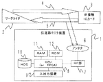
(基本ハードウェア構成)
図1に、本発明の特徴である伝送路モニタ装置1、リーダライタ2及びISO/IEC14443で規定されている非接触ICカード3で構成されるシステムを示す。4は、リーダライタ2から非接触ICカード3への伝送路を流れる信号を示し、5は、それとは逆の非接触ICカード3からリーダライタ2への伝送路を流れる信号を示している。
【0039】
リーダライタ2/非接触ICカード3間の信号は、伝送路モニタ装置1の構成要素であるアンテナ6で取得される。当該アンテナ6の仕様等の詳細については後述する。アンテナ6で受信された信号は、RF(高周波)部7で受信され、CPU(中央処理装置)又はFPGA(Field Programmable Gate Array )8の解析等の処理に供される。RAM(Ramdom Access Memory)11は、信号情報を一時的に記憶する等に利用され、ROM(Read Only Memory)12は、モニタ装置の起動処理を行うための命令等が格納されている記憶手段である。入出力装置9は、処理の入力や処理結果の出力に供され、キーボードやCRT(Cathode Ray Tube)等により実現されるものである。
【0040】
また、HDD(Hard Disk Drive )10は、CPU11がリーダライタ2と非接触ICカード3間の信号を解析する際の命令や実行形式を保存するために供される記憶手段である。本発明の特徴である伝送路モニタ装置1の構成要素である各手段は、このHDD10の内容によって具現化されるものである。
【0041】
次に、本発明の対象としているISO/IEC14443で規定されているリーダライタ2と非接触ICカード3間の通信について、その原理を簡単に説明しておく。なお、ISO/IEC14443についての詳細は、上述した文献に委ねることとする。
【0042】
(ISO/IEC14443規格のリーダライタ/非接触ICカードの通信規約)
リーダライタ2と非接触ICカード3間の通信は、13.56MHzの搬送波が利用されている。そして、リーダライタ2から非接触ICカード3への信号送信4は振幅変調方式が採用され、非接触ICカード3からリーダライタへの信号返信5は847.5kHzの副搬送波を利用した負荷変調方式が採用されている。
【0043】
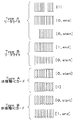
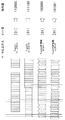
図2に、ISO/IEC14443に規定されている信号の波形を示す。前述したように、ISO/IEC14443には信号インターフェースとしてTypeAとTypeBと呼ぶ方式が規定されている。これらは、それぞれ変調方式がそれぞれ異なるものである。また、リーダライタ2から送信する信号の変調方式と非接触ICカード3から送信する信号の変調方式も異なる。
【0044】
したがって、図2に示しているとおり、TypeAとTypeBのそれぞれのリーダライタ2と非接触ICカード3により、波形が異なっている。なお、本図の波形の右にある英数字は、その信号のビット値を表したものである。
【0045】
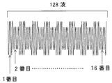
図3に図2にしめした波形の説明を詳細に示している。本図は、搬送波信号の波形を示し、図に示すように1ビット128波長からなっている(但し、本図においては64波長しかないが、図面作成の便宜上のため省略したものである。)。一方、副搬送波信号は1ビット16波長からなり、搬送波波長の8波長分である。すなわち、搬送波波長の8波長分である。そして、図3は、1ビット128波長の搬送波信号を副搬送波の波数16個で区切り、各部に1から16の番号を付すことを表している。図2は、このようにして得られた波形を、データ伝送方式、ビット毎に並べたものである。
【0046】
以上の基本ハードウェア構成、及びリーダライタ/非接触ICカード間のデータ伝送方式を踏まえて、本発明の装置例1を図4を参照しながら説明することとする。
【0047】
(装置例1)
図4に、本発明の装置例1に係る伝送路モニタ装置1の内部構成を示す。図に示すとおり、伝送路モニタ装置1は伝送路4、5を流れる信号を取得しデータ伝送方式を判別する機能を有するデータ伝送方式判別装置13と、当該データ伝送方式判別装置13の実行結果を表示する伝送路モニタ手段15からなる。
【0048】
データ伝送方式判別装置13の構成に付き、以下、詳細に説明する。データ伝送方式識別装置13は、伝送路4、5を流れる電磁波を受信し、時間とともに変化する電圧値に変換する機能を有する電圧取得手段14と、電圧取得手段14からの出力値から各種処理を行い、伝送方式を判別する各手段とから構成されている。
【0049】
まず、電圧取得手段14の構成について説明する。アンテナ16は、伝送路4、5を流れるリーダライタ2から送信される信号と、非接触ICカード3から送信される信号波形を受信する。当該アンテナ16は、例えば13.56MHzと共振するループアンテナ等が用いられ、伝送路内に設置される。
【0050】
信号増幅回路17は、アンテナ16で受信した電磁波の高周波電流を増幅するものであり、例えば、アンプなどにより構成される。ここで、アンプは受信した信号の大きさにあわせてゲインを自動的に調整する手段等を有していてもよい。
【0051】
信号増幅回路17から出力された増幅された信号波形は、ローパスフィルタ18に入力される。ローパスフィルタ18は、当該信号から13.56MHzの搬送波をマスクし、847.5kHzの副搬送波の信号電圧を出力する。図5、図6、図7にローパスフィルタ18の動作として、フィルタリングについての一例を示す。図5は、信号増幅回路17によって増幅された生信号波形の例であり、ここでは、非接触ICカード3からの信号を示しており、サンプリングレート66MS/s(MegaSamples/second)でサンプリングされている。
【0052】
図6は、ローパスフィルタによって、フィルタリングされた後の信号波形を示す。そして、最終的に、適当なしきい値で変換することにより、図7に示されるような方形波を得ることができる。
【0053】
このときの方形波は、例えば、最大値の電圧が1Vで、最小値の電圧が0Vの波形等であるが、最大値及び最小値の電圧は実装方法によって異なってもよい。
【0054】
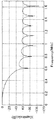
ここでは、ローパスフィルタとして、サンプリング周波数が3.39MHz、カットオフ周波数が0.3MHzの窓関数にHammingを使った20次のFIRフィルタを適用している。図8に適用したローパスフィルタの減衰特性の例を示しておく。なお、図7に示されるような方形波が得られれば、使用されるフィルタやそのフィルタリングについてはこれに限られない。
【0055】
以上のフィルタリングによって得られた方形波は、2値化手段19に入力されて2値化される。2値化手段19は、この方形波をサンプリングし、適当なしきい値を基準として電圧の大小により2値化する。図9に、この2値化過程の図を示す。図9(a)は、生信号波形であり、これをローパスフィルタにより方形波へ変換されたのが図9(b)、図9(c)は(b)に示す波形をしきい値を0.5Vとして、これを基準に電圧の大小から2値化している。ここでは、しきい値よりも電圧値が高いときは「1」((a)の信号波形において振幅が低いところ)を、しきい値よりも電圧値が低いときは「0」((a)の信号波形において振幅が高いところ)を与えている。その結果、2値化された信号データとして「000101010101」が得られる。
【0056】
また、2値化手段19は、信号増幅器17からの昇圧され出力された搬送波信号をローパスフィルタ18に入力し、その出力として得られた副搬送波信号からキャリブレーションを行う機能を有する。これは、アンテナ16と図1に示す伝送路4、5との距離の相違により受信する信号のレベルが異なるためである。具体的には、信号増幅器17によって昇圧された、伝送路4を流れる信号をローパスフィルタ18に入力し、その出力として得られた副搬送波信号の信号波形の頂点値を数ポイントづつ取得し、その電圧の平均値を信号計測のための基準値とする。これら信号電圧値はRAM等のメモリに一時的に記憶される。
【0057】
そして、取得した信号電圧の最大値と最小値の差を測定し、その範囲から無変調の搬送波であることを確認すると、先に算出された平均値を使ってしきい値を算出する機能を有する。
【0058】
ここで、平均値の求め方は、RAM等の一時記憶装置に保存した電圧を全て加算し、取得回数で除算する方法であってもよい。平均値から所定の割合(電圧値を「0」と「1」との2値データに分けるのに適当な割合)を減算した値がしきい値となる。
【0059】
また、このときのサンプリングレートは66MS/s(Mega−Samples per second )程度としてある。本発明実施の形態に示した13.56MHzの搬送波信号を判別するためには、サンプリング定理から、最小で13.56×2=27.12MS/sのサンプリングレートで信号電圧をサンプリングすればよいが、より高いS/N比(信号雑音比)を得るため、66MS/sで信号電圧をサンプリングしている。
【0060】
一方で、クロック生成回路20は、信号増幅回路17によって増幅された搬送波又はローパスフィルタ18からフィルタリングされた副搬送波の信号波形から頂点を検出して、各頂点の時間間隔を周期とするタイミングを参照クロックとして生成する。このとき、PLL(位相同期ループ)等が用いられる。また、信号増幅回路17によって増幅された信号のゼロクロス点を求めて、そのタイミングを参照クロックとしてもよい。
【0061】
以上が、電圧取得手段14内の各部の機能であり、最終的には、2値化された信号データと、クロックが出力され、データ伝送方式判別装置13のその他の各手段の処理に供される。
【0062】
次に、本発明の特徴である2値化された信号データから特徴点を抽出する過程を実現する各手段につき説明することとするが、前提となる各用語の意味に付き、図10を用いて先に説明しておく。
【0063】
本図においては、TypeAの非接触ICカード3の[01]ビットの信号を例として示している(この信号波形は、図2のTypeA非接触ICカード3の[0]ビットと[1]ビットの信号波形を用いて得られるものである。)。本発明では、信号2ビット分のデータでデータ伝送方式が異なるリーダライタ2及び非接触ICカード3からの信号を判別することができるため、2ビット分の信号が必要となる。
【0064】
ここで、信号の下に付された「10101010000000000000000010101010」という数字列はアナログ−デジタル変換によりデジタルデータとされたものであり、信号の電圧値を示すものである。以下、この信号を例として各用語の説明をする。
【0065】
先ず、「特徴点」とは、図示されているように、伝送路を流れる信号の中から、値を取得するタイミングを示すものである。本図においては、特徴点は、特徴点1〜特徴点5として矢印で示される5点と特徴点抽出開始位置として矢印で示される1点である。また、このタイミングは、判別したいデータ伝送方式の信号波形毎に予め定まっているものである。
【0066】
そして、この特徴点の信号値(図10における「1」、「0」、「0」、「0」、「0」、「0」)は、選択された特徴点の位置の信号の電圧値である。「特徴点抽出開始位置」とは、特徴点を取得する一番最初のタイミングであり、本発明の実施形態では最初に「1」が出現したときとしてある。この点の詳細は後述する。
【0067】
「特徴点群」とは、これら特徴点の電圧値を並べた時の値であり、本図においては、「100000」である。この値が、判別条件値と比較するための値となる。
【0068】
「判別条件値」は、判別するデータ伝送方式の信号の特徴点群の電圧値の取る値の範囲であり、本図においては、TypeAの非接触ICカード3の信号を用いているため、その範囲は「100000」([01]ビット信号)≦TypeAカード≦「101010」([10]ビット信号)である。
【0069】
ここで、[10]ビット信号の場合は、上述したように、最初に「1」が出現したときを「特徴点抽出開始位置」としているため、図2においてTypeAの非接触ICカード3の[1]ビット信号と[0]ビット信号を並べたものを図10で示したものと同様の方法に従い特徴点を抽出することにより得られたものである。
【0070】
本図においては、抽出された特徴点群が「100000」であるため、100000≦TypeAカード≦101000の範囲にあり、判別対象の信号は、TypeAの非接触ICカード3からリーダライタ2へ返信された信号であることがわかる。
【0071】
以上の各用語の定義を元にして、図4の残りの各手段に付き説明する。特徴点抽出開始位置特定手段21は、電圧取得手段14の2値化手段19より出力された2値化された信号データから特徴点抽出開始位置の検出を開始する。このとき、2値化された信号データの値が「0」か「1」かを判別することによって検出が行われる。本発明の実施形態では、最初に「1」を検出した位置を特徴点抽出開始位置としている。
【0072】
ここで、測定を開始した位置の値が「1」であったときは誤判別が生じうる可能性がある。この点を図11を参照しながら説明する。本図においては、信号振幅が小さい点(これに「1」というデジタルデータを付している。)から計測を開始している。この場合、上述した特徴点を抽出するタイミングで特徴点を抽出していくと、得られた特徴点群は正規の判別条件値に適合するものではない。
【0073】
したがって、このような誤判別を防ぐために、図11に示すように、一度信号振幅が上がった後、一番最初に下がった点を特徴点抽出開始位置としている。
【0074】
特徴点抽出開始位置特定手段21は、上記した誤判別を以下のように防止する機能を有している。即ち、測定を開始した位置が「1」であるというフラグをRAMなどの一時記憶に記憶し、特徴点抽出開始位置を検出している間はフラグが未だ存在しているかどうかを適時確認する。
【0075】
フラグが立っている間は、「1」を検出してもそれが正当な特徴点抽出開始位置とはならないため、何も処理せず、検出を続ける。そして、「0」が検出されると、フラグをRAMなどから消去する。次に「1」が検出されると、当該位置を特徴点抽出開始位置であると認識し、特徴点抽出開始位置を決定する。ここで、このフラグは一時記憶に保存される変数であってもよく、実現する手段の別を問うものではない。
【0076】
特徴点抽出タイミング情報記憶手段23は、特徴点を抽出するときのタイミング間隔の情報を記憶している。この特徴点抽出タイミング情報は、特徴点抽出開始位置特定手段21によって特定された特徴点抽出開始位置を起点として、どのタイミングで信号を取得していくかが記載されているものである。当該タイミング情報を例示すると以下のようになる。
【0077】
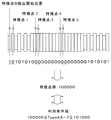
例えば、TypeAリーダライタ2及びTypeA非接触ICカード3と、TypeBリーダライタ2及びTypeB非接触ICカード3とを判別したい場合には、図3で示した1番目の部分を特徴点抽出開始位置とすると、続く2、9、10、17、18番目の各部を特徴点抽出タイミングとし、これらの番号を付された位置の信号を順次取得していくように情報が構成されている。ここで、上述したように、データ伝送方式の判別には2ビット分の信号が必要であるため、17、18番目の値は続くビットの最初の1、2を示すものである。図12に他のデータ伝送方式に従うリーダライタ2や非接触ICカード3の信号波形から特徴点群を抽出する流れを示す。本図において棒線は特徴点の位置を示す。
【0078】
また、TypeBリーダライタ2及びTypeB非接触ICカード3を判別したい場合には、1の次に2を取得すれば、判別が可能であるため、これらの特徴点抽出タイミングが情報として構成されている。
【0079】
従って、実際の情報形式は、「判別対象の伝送方式の組合せ、特徴点」として、
「TypeAリーダライタ・TypeA非接触ICカード・TypeBリーダライタ・TypeB非接触ICカード:2、9、10、17、18
TypeBリーダライタ・TypeB非接触ICカード:2
…」
のように保存されている。
【0080】
なお、保存形式は、テキスト形式やCSV形式等、後述する特徴点抽出手段22によって可読であればよく、特に限定されるものではない。
【0081】
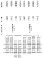
特徴点抽出手段22は、特徴点抽出開始位置特定手段21から取得した特徴点抽出開始位置と特徴点抽出タイミング情報記憶手段23に格納される特徴点抽出タイミング情報を用いて特徴点を抽出していく。ここで、特徴点を抽出していく際の信号周期のタイミングは、電圧取得手段14のクロック生成回路20にて生成されたクロックが用いられる。このようにして、特徴点抽出手段22は、特徴点の信号値を取得していく。ここで、図13、図14にTypeAリーダライタ2、TypeBリーダライタ2、TypeA非接触ICカード3及びTypeB非接触ICカード3のそれぞれの2ビットデータ分の特徴点群の値を示しておく。本図において、棒線は特徴点の位置(1、2、9、10、17、18)を示している。
【0082】
伝送方式判別条件記憶手段25には、伝送方式を判別するときの条件である伝送方式判別条件情報が記憶されている。当該条件の情報は、例えば、以下のように記述されている。
【0083】
「100000≦x≦101000:TypeA非接触ICカード
101001≦x≦101010:TypeB非接触ICカード
110000≦x≦110011:TypeAリーダライタ
111100≦x≦111111:TypeBリーダライタ」
【0084】
ここで、xは特徴点抽出手段22から得られた特徴点群であり、xが上記の4条件の内の範囲のどれかに該当すれば、該当する信号を発した媒体が判別できるというものである。なお、保存形式は、テキスト形式やCSV形式等、後述する伝送方式判別手段24によって可読であればよく、特に限定されるものではない。これにより、判別したいデータ伝送方式の変更に対応して無駄な処理を行うことなく高速にデータ伝送方式を判別することが可能となる。
【0085】
伝送方式判別手段24は、特徴点抽出手段22から得られた特徴点群をこの伝送方式判別条件情報と比較し、データ伝送方式を判別する。最終的には、伝送路モニタ手段3によって判別結果が出力される。
【0086】
以下、例外的な処理について説明しておく。例外的な処理としては2点あり、(1)TypeBリーダライタ2からの信号でビットが「1」から始まるものについては、無変調の信号と見分けがつかず、(2)特徴点抽出開始位置が信号の途中であった場合には、他の信号方式と誤判別してしまう場合がある。
【0087】
上記(1)の問題点の場合には、ビットが「0」が出現してから判別を開始することで解決できるため、特徴点開始位置特定手段21は特段の処理を行うことなく、この問題点に対処できる。
【0088】
上記(2)の問題点の場合については、図15を参照して説明する。本図において、TypeBの非接触ICカードで[01]ビットの信号の途中で計測を開始しており、開始位置の次の状態が[0]の値を取るため、この点を特徴点抽出開始位置として特徴点を抽出している。
【0089】
その結果、抽出された特徴点群は「100101」という値になり、信号を送信した対象がTypeBの非接触ICカードであるにもかかわらず、上記した伝送方式判別条件情報と比較するとTypeAの非接触ICカードとなってしまい、誤判別となる(「100000≦x≦101000」)。
【0090】
しかし、図15をみてわかるとおり、「100101」という条件値はTypeAの非接触ICカードには存在しないので、この状態をTypeBの非接触ICカードに対する例外値として含めるによって、問題を回避できる。同様にして、全ての誤判別のケースを考慮して、TypeBの非接触ICカードの許容範囲を「101101」まで広げ、「110100」を例外値として含めることで、TypeAリーダライタ2、TypeA非接触ICカード3、TypeBリーダライタ2及びTypeB非接触ICカード3の判別が可能となる。
【0091】
以上の例外処理を考慮し、データ伝送方式判別条件記憶手段25に、TypeB非接触ICカード3に対する例外値として「100101」と「110100」を判別条件として記憶させておく。これにより、通信の途中であってもデータ伝送方式を判別することが可能となる。
【0092】
以上、本発明の実施形態に係る装置例1について説明してきたが、装置構成は本発明の目的を達成する範囲内においては適宜変更して実施可能である。
【0093】
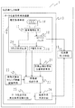
(方法例1)
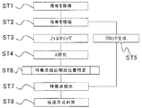
続いて、前記の装置例1を用いたデータ伝送方式判別方法につき、図16を参照しながら説明する。図16は、本発明の実施形態に係る方法例1の処理を表すフロー図である。
【0094】
先ず、電圧取得手段14内のアンテナ16が伝送路を流れる信号4、5を受信し(ST1)、信号増幅回路17により、当該信号を認識可能な電圧まで昇圧する(ST2)。
【0095】
次に、増幅された信号をローパスフィルタ18によりフィルタリングする(ST3)。このフィルタリング処理は、上述したように、13.56MHzの搬送波をマスクし、847.5kHzの副搬送波の電圧信号を取り出す。そして、ローパスフィルタ18から出力される波形は、最大値が1Vで最小値が0Vの方形波となる。前述した通り、この時の最大値及び最小値の電圧は実装方法によって異なってもよい。
【0096】
次に、ローパスフィルタ18によって出力された方形波を、2値化手段19によって2値化する(ST4)。このときのしきい値は、最大値が1Vで最小値が0Vの方形波にあっては、例えば0.5Vとする。この結果、2値化されたデータは、例えばTypeAリーダライタ2の[01]ビットを表す信号にあっては、図12から読み取れるように、「11100000000000000000000011100000」となる(ここでは、振幅が大きい部分を「0」とし、振幅が小さい部分を「1」としている。)。
【0097】
また、クロック生成回路20は、信号増幅回路17によって増幅された搬送波又はローパスフィルタ18からの副搬送波の周期を利用してクロックを生成する(ST5)。当該クロックは、特徴点抽出手段22が特徴点を抽出していく処理に供されるものである。クロックの生成は、前述のとおり、PLLなどを用いる。
【0098】
以上の処理の結果として、電圧取得手段14からは2値化されたデータとクロックが出力され、これらを用いてリーダライタ2、非接触ICカード3間のデータ伝送方式を判別するための特徴点を抽出していくことになる。
【0099】
電圧取得手段14から出力された2値化された信号データは、特徴点抽出開始位置特定手段21に入力され、当該データから特徴点抽出開始位置が決定される(ST6)。図17に当該処理を具体的に説明してある。以下、本図につき説明していくことにする。
【0100】
先ず、入力された2値化されたデータの計測開始点の信号値を取得する(ST61)。この2値化されたデータは、例えばTypeAのリーダライタ2からの[01]ビット信号である場合には、上記した通り「11100000000000000000000011100000」である。
【0101】
次に、当該計測開始点の信号値が「0」であるか「1」であるかの判断処理が行われる(ST62)。本発明の実施形態では、最初に「1」が出現したときを特徴点抽出開始位置と規定しているため、計測開始点の信号値が「0」である場合と、「1」である場合とで、別処理を行わなければならないからである。
【0102】
信号値が「0」の場合には、次の処理として、計測開始点の次の信号値の値を取得する(ST63)。そして、この信号値が「0」である場合には、さらに次の信号値を取得する(ST63)。この処理は、信号値が「1」となるまで繰り返すことになる(ST64)。
【0103】
最終的に、ST64の判断処理で、信号値が「1」であると判断された場合には、次の処理に移り、この信号値の対応する点が特徴点抽出開始位置であると認定される(ST69)。
【0104】
また、計測開始点での信号値を取得した結果、信号値が「1」であると判断された場合には(ST62)、これを特徴点抽出開始位置と判定すると、他のデータ伝送方式と誤判別する可能性があるので、一度「0」が出現してから、その後に「1」が出現した点を特徴点抽出開始位置とするようにする。
【0105】
この処理につき説明する。ST62で信号値が「1」と判断されると、RAM等の一時記憶装置に、計測開始点としてふさわしくないことを意味するフラグを立てる(ST65)。続いて、次の信号値を取得し(ST66)、この信号値が「0」であるか「1」であるかを判断する(ST67)。「1」と判断された場合には、さらに次の信号値を取得し(ST66)、ST67の判断処理を受けることになる。これらの処理は、「0」の信号値が得られるまで、繰り返される。
【0106】
ST67の処理で、信号値が「0」であると判断されると、フラグは消去される(ST68)。以後の処理は、ST62で信号が「0」であると、判断された場合の処理と同じ処理が実行されるため(ST63)、説明は省略する。
【0107】
以上の特徴点抽出開始位置特定処理(ST6)の実行後、特徴点抽出開始位置が特定され、特徴点抽出手段22は、この特徴点抽出開始位置を起点として、特徴点抽出タイミング情報記憶手段23に格納された特徴点抽出タイミング情報に記述されたタイミングで特徴点を抽出していく(ST7)。ここで、信号の周期間隔のタイミングはクロック生成回路から生成されたクロックが用いられる(ST7)。
【0108】
また、特徴点抽出タイミング情報記憶手段23に格納された特徴点抽出タイミング情報は、前述したように、
「TypeAリーダライタ・TypeA非接触ICカード・TypeBリーダライタ・TypeB非接触ICカード:2、9、10、17、18
TypeBリーダライタ・TypeB非接触ICカード:2…」
という形式で格納されている。
【0109】
特徴点抽出処理(ST7)の例として、TypeAリーダライタ2、TypeA非接触ICカード3、TypeBリーダライタ2、TypeB非接触ICカード3のデータ伝送方式を判別したい場合につき、説明する。
【0110】
ISO/IEC14443で規定されているTypeAリーダライタ2の[0]ビット+[1]ビットの信号値は、図12に示すとおり、「11100000000000000000000011100000」である。したがって、特徴点抽出開始位置は「1」となる。
【0111】
そして、特徴点抽出タイミング情報は、「2、9、10、17、18」であるから、特徴点抽出開始位置を1番目の信号値として、順次2番目、9番目、10番目、17番目、18番目の信号値を取得していくことになる。したがって、実行においては、まず、特徴点抽出開始位置の信号値である「1」をCPU内のレジスタに代入し、それから1ビットシフトして「10」として、次の特徴点抽出位置である2番目の信号値「1」を代入して特徴点群として「11」を得る。この処理を、9番目、10番目、17番目、18番目の信号値についても繰り返すと、結果として特徴点群「110000」を得る。
【0112】
この例以外の特徴点抽出処理は、各データ伝送方式のリーダライタ2や非接触ICカード3にビットデータの信号値や特徴点群が図13、図14に示されているので、上述した例と同様に実行されるため、説明は省略する。
【0113】
このように、判別したいデータ伝送方式の変更に対応して、無駄な処理を行うことなくデータ伝送方式を判別できるので、高速な判別が可能となる。
【0114】
特徴点抽出処理(ST7)により、特徴点群が抽出されると、伝送方式判別手段24は、当該特徴点群とデータ伝送方式判別条件記憶手段に記憶されているデータ伝送方式判別条件とを比較して、データ伝送方式を判別する(ST8)。ここで、データ伝送方式判別条件は上記したように、以下のような形式で保存されている。
【0115】
「100000≦x≦101000:TypeA非接触ICカード
101001≦x≦101010:TypeB非接触ICカード
110000≦x≦110011:TypeAリーダライタ
111100≦x≦111111:TypeBリーダライタ」
ここで、xは特徴点抽出手段22から得られた特徴点群であり、xが上記の4条件の内の範囲のどれかに該当すれば、該当する信号を発した媒体が判別できるというものである。
【0116】
そして、先の例で得られたTypeAのリーダライタ2の[01]ビットの特徴点群は「110000」であるため、データ伝送方式判別条件と照らし合わせると110000≦x≦110011の条件式を満たしているため、データ伝送方式判別対象となる媒体はTypeAリーダライタ2であることがわかる。
【0117】
これにより、読み取った信号をデコードすることなく、低レイヤでデータ伝送方式を判別することができるので、非常に高速な判別が実現される。
【0118】
以下、前述した例外的な処理についての本方法例1による回避策につき説明する。前述した通り、例外的な処理としては2点あり、(1)TypeBリーダライタ2からの信号でビットが「1」から始まるものについては、無変調の信号と見分けがつかず、(2)特徴点抽出開始位置が信号の途中で会った場合には、他の信号方式と誤判別してしまう場合がある。
【0119】
上記(1)の問題点の場合には、ビットが「0」が出現してから判別を開始することで解決できる。TypeBのリーダライタ2のビット[0]の信号値の1番目の値は1であるため、次に0が出現するときに判別を開始すればよく、ST6による処理を特段変更することなく、この問題に対処できる。
【0120】
また、上記(2)の問題点の場合については、前述した通り、データ伝送方式判別条件として、TypeB非接触ICカード3に対する例外値として「100101」と「110100」をも判別条件として含めることにより、ST8の処理は特段の変更も無く、この問題に対処できることになる。これにより、通信の途中であってもデータ伝送方式を判別することが可能となる。
【0121】
以上、本発明の実施形態にかかる方法例1につき説明してきたが、フィルタリング処理(ST3)、2値化処理(ST4)や特徴点抽出開始位置特定処理(ST6)等は、前述した例にとらわれるもので無く、本方法例1の実施により得られる効果を奏する範囲内で、適宜実施変更可能である。
【0122】
(装置例2)
以下に、本発明の実施形態に係る装置例2を図18を参照しながら説明する。装置例2は、装置例1に係る電圧取得手段14においてローパスフィルタ18を設けていない点が異なっているものである。すなわち、本装置例2は、装置例1と2値化する手段が異なっている。したがって、この点のみ説明し、重複する構成手段についてはその説明を省略することとする。
【0123】
アンテナ16が伝送路を流れる電磁波信号4、5を受信すると、当該信号は信号増幅回路17により、信号電圧が他の手段によって認識可能となるまで昇圧される。
【0124】
クロック生成回路20は、信号増幅器17からの昇圧された搬送波信号を受信し、クロックを生成する。クロックは、搬送波信号の頂点値を取得していき、頂点値群の周期からクロックを生成していくことになる。また、クロック生成回路20は、生成したクロックを特徴点抽出手段22と2値化手段19´に出力する。
【0125】
一方、2値化手段19´は、信号増幅器17からの昇圧された搬送波信号からキャリブレーションを行う機能を有する。これは、アンテナ16と図1に示す伝送路4、5との距離の相違により受信する信号のレベルが異なるためである。具体的には、信号増幅器17によって昇圧された、伝送路4を流れる信号の信号波形の頂点値を数ポイントづつ取得し、その電圧の平均値を信号計測のための基準値とする。これら信号電圧値はRAM等のメモリに一時的に記憶される。
【0126】
そして、取得した信号電圧の最大値と最小値の差を測定し、その範囲から無変調の搬送波であることを確認すると、先に算出された平均値を使ってしきい値を算出する機能を有する。
【0127】
ここで、平均値の求め方は、RAM等の一時記憶装置に保存した電圧を全て加算し、取得回数で除算する方法であってもよい。また、無変調の搬送波周波数を使うのは、取得した信号に含まれる無変調の信号と変調された信号の割合によってしきい値が変化してしまうことを避けるためである。そして、取得した最大値と最小値の差が測定誤差範囲内である場合に取得した値群は無変調であると認識され、平均値から所定の割合(電圧値を「0」と「1」との2値データに分けるのに適当な割合)を減算した値がしきい値となる。
【0128】
また、2値化手段19´は、クロック生成手段20´から入力されたクロックを用いて、搬送波信号のサンプリングを行う。この時のサンプリングレートは装置例1で説明した通り、66MS/s程度でよい。最終的に、特徴点を抽出していく際に必要となる2値化されたデータは、128波の搬送波を1ビット当たりの副搬送波の波数である16で区切ったものである点は、装置例1と同様である(図3参照)。そのため、クロックを利用して、搬送波8波毎に信号を取得していく。
【0129】
最終的に、2値化手段19´は、サンプリングされた信号を先に求めたしきい値により、2値化する。即ち、しきい値よりも電圧が高ければ「0」とし、電圧が低ければ「1」と判断する。この作業は、図19に示している。本図において、(a)は生信号波形を示し、(b)はこの信号波形の頂点値を適当なしきい値(ここでは、125mVとしている。)を基準として2値化している。結果として、「…010…」という2値化されたデータが得られる。
【0130】
ここで、信号増幅回路17を実現するアンプが信号の大きさを自動的に調整する機能を有する場合には、キャリブレーションを行わなくてもよく、その場合は、予め設定されたしきい値が用いられる。
【0131】
このようにして、2値化されたデータが電圧取得手段14´から出力され、以後、特徴点抽出開始位置特定手段21や特徴点抽出手段22の処理の用に供される。これら手段は、装置例1と同様であるため説明は省略する。
【0132】
以上、装置例2につき説明してきたとおり、伝送路4、5を流れるリーダライタ2又は非接触ICカード3からの搬送波信号を直接2値化することで、ローパスフィルタを介さずとも、装置例1と同様な効果を奏することが可能となる。
【0133】
(方法例2)
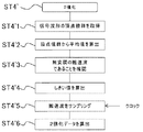
続いて、前記の装置例2を用いたデータ伝送方式判別方法につき、図20を参照しながら説明する。図20は、本発明の実施形態に係る方法例2を処理を表すフロー図であるが、2値化する処理が方法例1と異なるのみであるので、2値化する処理のみ詳細に説明することとする。
【0134】
先ず、伝送路4、5を流れる搬送波信号をアンテナによって取得し(ST1)、当該搬送波信号は認識可能な電圧まで増幅される(ST2)。その後、この増幅された信号は、クロック生成回路により、信号電圧の頂点値群を検出し周期を取得することにより、クロックが生成される(ST5)。
【0135】
次に、増幅された搬送波信号は、2値化手段19´によりキャリブレーション過程に供される。2値化処理の詳細を図21に示す。先ず、信号増幅回路17により増幅された搬送波信号の波形から頂点値群を取得していく(ST4´1)。このとき、頂点値群はRAM等の一時記憶装置に保存する。次に、頂点値群からキャリブレーションの基準値とされる平均値を算出する(ST4´2)。平均値は、頂点値群の電圧値をすべて加算し、取得回数で除算する方法を採用するが、算出方法はとくに、これに限られるものではない。
【0136】
次に、取得した頂点値群の電圧値の最大値と最小値の差から、取得した信号の範囲が無変調の搬送波であることを確認する(ST4´3)。この確認は、上述したとおり、後にしきい値を求める際に、取得した信号に含まれる無変調の信号と変調された信号の割合によってしきい値が変化してしまうことを避けるためである。
【0137】
次に、平均値から2値化するに最適となる程度に所定の割合を減算して、しきい値を算出する(ST4´4)。
【0138】
続いて、2値化手段19´は、信号増幅回路17からの増幅された搬送波信号の波形をクロック生成回路20´により入力されたクロックを用いてサンプリングする(ST4´5)。この時のサンプリングレートは、前述したとおり、66MS/s程度である。このサンプリングは、クロックを利用して、搬送波8波毎に信号を取得していく。
【0139】
最終的に、2値化手段19´は、ST4´4で求めたしきい値をもとにサンプリングされた信号を2値化する(ST4´6)。ここでは、しきい値よりも信号電圧が高ければ「0」とし、信号電圧が低ければ「1」とする。
【0140】
以上の処理を順次実施することにより、2値化されたデータが出力され、以後の特徴点開始位置特定処理(ST6)、特徴点抽出処理(ST7)が順次実施されていく。
【0141】
以上、本発明の実施形態に係る装置例1及び方法例1並びに装置例2及び方法例2について説明してきたが、本発明を実施する際には、必ずしも上記した手段、手法に限定されるものではなく、下記する効果を奏する範囲において適宜変更実施することが可能なものである。
【0142】
例えば、2値化手段での処理は、特徴点を抽出した後でもよい。この場合には、特徴点群抽出開始位置特定手段に包絡線の検波をする機能を持たせ、特徴点抽出手段は当該信号電圧を受信し、特徴点を抽出できるように機能構成をしておくことで対処でき、その後に2値化することを除けば、特段の変更無く本発明の実施形態に係る各装置例で実施することができる。本方法例についても同様である。
【0143】
【発明の効果】
以上説明したように、本発明によれば、伝送路を流れる信号を取得し、データ伝送方式に特有な信号値である特徴点を取得し、これを予め記憶されているデータ伝送方式に特有の判別条件と比較することが可能となるため、複数のデータ伝送方式のいずれで通信が行われているか不明なリーダライタ及び非接触ICカードのデータ伝送方式を適切に判別することができる。
【0144】
また、特徴点を抽出する開始位置が不適切であった場合には、特徴点抽出開始位置を再度変更したり、抽出された例外値を予め判別条件として記憶させることで、通信の途中であってもデータ伝送方式を判別することが可能となる。
【0145】
また、本発明では、取得した信号をデコードすることなく、判別のためのデータとして使用することができるので、低レイヤでデータ伝送方式を判別することができ、また、判別処理も非常に高速なものとなる。
【0146】
また、判別条件は、判別したいデータ伝送方式の組合せという形式で記述されているため、判別したいデータ伝送方式の変更に対応してデータ伝送方式を判別することができるようになるため、無駄な処理を行うことがなく非常に高速に判別することを可能としている。
【図面の簡単な説明】
【図1】本発明の実施形態に係る伝送路モニタ装置の基本ハードウェア構成を示す図である。
【図2】ISO/IEC14443に規定されるTypeA、TypeBのリーダライタ及び非接触ICカードの信号1ビット分の波形を示す図である。
【図3】リーダライタ、非接触ICカードの搬送波を副搬送波の波数分で区切り、各部分に番号を付す際の説明を示している図である。
【図4】本発明の実施形態に係る装置例1の伝送路モニタ装置のブロック図である。
【図5】ローパスフィルタによってフィルタリングされていく過程の各段階での信号波形を示すものであり、非接触ICカードからリーダライタへ送信される生信号波形である。
【図6】図5に示す波をローパスフィルタを通した後の波形を示す。
【図7】図6に示す波を適当なしきい値により方形波に変換された後の波形を示す。
【図8】各ローパスフィルタの減衰特性を示す図である。
【図9】ローパスフィルタを通した信号から2値化された信号データを生成する過程のイメージを示す図である。
【図10】本発明の各用語の定義を説明する図である。
【図11】特徴点抽出開始位置を検出する方法を示す図である。
【図12】特徴点を抽出する方法を示す図である。
【図13】TypeA、TypeBそれぞれのリーダライタの2ビット信号の組合せの特徴点群を示す図である。
【図14】TypeA、TypeBそれぞれの非接触ICカードの2ビット信号の組合せの特徴点群を示す図である。
【図15】TypeBの非接触ICカードの特徴点抽出開始位置を誤って決定してしまった場合に発生する誤判別を説明するための図である。
【図16】本発明の実施形態に係る方法例1のフローを示す図である。
【図17】本発明の実施形態に係る方法例1の特徴点抽出開始位置特定処理の詳細を示すフロー図である。
【図18】本発明の実施形態に係る装置例2の伝送路モニタ装置のブロック図である。
【図19】信号の頂点値群から2値化された信号データを生成する過程のイメージを示す図である。
【図20】本発明の実施形態に係る方法例2のフローを示す図である。
【図21】本発明の実施形態に係る方法例2の2値化処理の詳細を示すフロー図である。
【図22】ISO/IEC14443で規定されるTypeAのリーダライタから非接触ICカードへのリクエストコマンドの一例を示す図である。
【図23】ISO/IEC14443で規定されるTypeBのリーダライタから非接触ICカードへのリクエストコマンドの一例を示す図である。
【符号の説明】
1、1´…伝送路モニタ装置
2…リーダライタ
3…非接触ICカード
4…リーダライタから非接触ICカードへの伝送路を流れる信号
5…非接触ICカードからリーダライタへの伝送路を流れる信号
6…アンテナ
7…RF部
8…CPUまたはFPGA
9…入出力装置
10…HDD
11…RAM
12…ROM
13…データ伝送方式判別装置
14、14´…電圧取得手段
15…伝送路モニタ手段
16…アンテナ
17…信号増幅回路
18…ローパスフィルタ
19、19´…2値化手段
20…クロック生成回路
21…特徴点抽出開始位置特定手段
22…特徴点抽出手段
23…特徴点抽出タイミング情報記憶手段
24…伝送方式判別手段
25…データ伝送方式判別条件記憶手段[0001]
TECHNICAL FIELD OF THE INVENTION
According to the present invention, when communication is performed between a non-contact IC card and a reader / writer using a plurality of data transmission methods, a signal flowing through a transmission path is obtained, and the data transmission method is determined using the signal. The present invention relates to a method of determining a data transmission method between a contact IC card / reader / writer and a transmission path monitoring device.
[0002]
[Prior art]
In recent years, as a data transmission method between a non-contact IC card and a reader / writer, a plurality of methods have been proposed and standardized. Also, non-contact IC cards compatible with communication using such a plurality of data transmission methods have been developed.
[0003]
However, when developing a non-contact IC card system, it is necessary to monitor a communication signal flowing through a transmission path between the non-contact IC card and the reader / writer for system debugging and the like. It is necessary to monitor after specifying the specified data transmission method, and when communication is performed using an unspecified data transmission method, it is necessary to switch the specification and monitor.
[0004]
Hereinafter, a conventional method for determining a data transmission method in a contactless IC card system will be described. First, a signal read from a transmission path is decoded and becomes readable information, and then a data transmission method is determined by referring to a position describing a transmission method of communication contents. Fig. 22 and Fig. 23 show an example of a command from a reader / writer of Type A and Type B based on the communication protocol of a non-contact IC card specified in ISO / IEC14443 (International Organization Standardization / International Electrotechnical Commission 14443). Hereinafter, first, description will be given with reference to FIG.
[0005]
FIG. 22 shows a request command from a Type A reader / writer specified by ISO / IEC14443. In this figure, S is a block head bit in a Type A non-contact IC card, b1 to b7 are data bits, and E is a block end bit in a Type A non-contact IC card. REQA is a request command from a type A reader / writer, and FIG. 22 illustrates a bit collision and a time slot as commands.
[0006]
FIG. 23 shows a request command from a Type B reader / writer. In this figure, Apf is a parameter used in REQB which is a request command from a Type B reader / writer, AFI is an application field identifier, PARAM is a parameter of attribute information, and CRC_B is a cyclic redundancy check code B. b1 to b7 and b8 are data bits. As described above, REQB is a request command from a Type B reader / writer. In this drawing, a slot marker and a time slot are exemplified as commands.
[0007]
When the data transmission method is different, as can be seen from FIGS. 22 and 23, the request command to the contactless IC card transmitted from the reader / writer before starting communication is different. At this time, each of the non-contact type IC cards of Type A and Type B returns a response only to the corresponding request command, so that it was possible to determine the data transmission method.
[0008]
Also, if the anti-collision method is different even if the data transmission method is the same, the parameters of the request command are different, as can be seen from the portions circled in FIGS. It was possible to determine whether or not it was his own purpose.
[0009]
The following is a list of literature information that is helpful for these conventional techniques.
[Non-patent literature]
"JICSAP IC Card Specification V2.0 Part 2 Proximity Type IC Card", [online], [Search April 21, 2003], Internet <URL: http: // www. jicsap. com / stdwork / kinsetsu. pdf>
[0010]
[Problems to be solved by the invention]
However, in the above-described conventional method, if the data transmission method between the non-contact IC card and the reader / writer is unknown, it is impossible to monitor the signal flowing through the transmission path because the signal cannot be encoded. Therefore, particularly when trying to monitor a non-contact IC card compatible with a plurality of data transmission methods, the data transmission method cannot be specified, which has been a particularly significant problem.
[0011]
Here, the main objects to be solved by the present invention are as follows.
That is, a first object of the present invention is to obtain a signal between a non-contact IC card and a reader / writer capable of communicating by a plurality of data transmission methods and determine the data transmission method by analyzing the signal waveform. It is an object of the present invention to provide a method of determining a data transmission method between a non-contact IC card and a reader / writer and a transmission path monitoring device.
[0012]
A second object of the present invention is to provide a method of determining a transmission method between a non-contact IC card / reader / writer and a transmission path monitor which can determine a data transmission method even during communication. No device is provided.
[0013]
A third object of the present invention is to determine a data transmission method by analyzing signal data itself without decoding a read signal. And a method of determining a transmission method between a reader / writer and a transmission path monitoring device.
[0014]
A fourth object of the present invention is to provide a method and a method for determining a transmission method between a non-contact IC card and a reader / writer, which enable a determination to be made only within a specified range by specifically specifying a data transmission method to be determined. It is intended to provide a road monitoring device.
[0015]
Other objects of the present invention will become apparent from the description of the specification, drawings, and particularly from the claims.
[0016]
[Means for Solving the Problems]
In order to solve the above problem, the method of the present invention is a method of determining a data transmission method from a signal flowing through a transmission path between a non-contact IC card and a reader / writer. Obtaining a signal flowing through the transmission path, then performing a binarization process using the voltage value of the waveform of the obtained signal, and subsequently determining the data transmission method from the binarized signal data The extraction start position of a feature point that can be a feature is detected, and the extraction start position of the feature point is used as a starting point. Therefore, the signal values of the feature points are extracted to form a feature point group, and finally, the values of the feature point group are recorded with a plurality of signal values unique to the data transmission method stored in advance. Compared to data transmission method determination condition information, take technique of determining the data transmission method.
[0017]
In order to solve the above problem, the present invention is a transmission path monitoring device that determines a data transmission method from a signal flowing through a transmission path between a non-contact IC card and a reader / writer, and acquires a signal flowing through the transmission path, Voltage acquiring means for binarizing the signal and outputting it as binarized signal data, and a characteristic point which can be a feature when discriminating the data transmission system from the binarized signal data from the voltage acquiring means. A feature point extraction start position specifying means for specifying an extraction start position of the feature point; a feature point extraction timing information storage means storing feature point extraction timing information describing a timing of extracting the feature point; Feature point extracting means for extracting a feature point value from the obtained signal data in accordance with the feature point extraction timing information to form a feature point group; A data transmission method discriminating condition storing means storing data transmission method discriminating condition information in which a signal value specific to the method is described, comparing the feature point group and the data transmission method discriminating condition information, and The present invention is characterized in that there is provided a transmission method determining means for determining and a transmission path monitoring means for outputting the determined data transmission method.
[0018]
More specifically, in solving the problem, the present invention achieves the above object by adopting a novel characteristic configuration method or means ranging from a superordinate concept to a subordinate concept to be enumerated below. Done.
[0019]
A first feature of the method of the present invention is a method of determining a data transmission system from a signal flowing through a transmission path between a non-contact IC card and a reader / writer, and first, a method for determining a data transmission method between the non-contact IC card and the reader / writer. Obtain a signal flowing through the transmission path, and then perform a binarization process using the voltage value of the waveform of the obtained signal, and subsequently determine the data transmission method from the binarized signal data. A feature point extraction start position of a feature point that can be a feature is detected, and, based on the feature point extraction start position, a pre-stored feature point extraction timing is described according to feature point extraction timing information. The signal values of the feature points are extracted to form a feature point group, and finally, the value of the feature point group is described with a plurality of signal values unique to the data transmission method stored in advance. Day Compared to transmission method determination condition information, in the configuration adopting the data transmission method determination method between the non-contact IC card / reader writer made to determine the data transmission method.
[0020]
According to a second feature of the method of the present invention, the binarizing process in the first feature of the present invention extracts a subcarrier signal from a carrier signal flowing through the transmission path through a filter, and forms a waveform of the subcarrier signal. The present invention employs a configuration of a data transmission method discrimination method between a non-contact IC card / reader / writer which binarizes the level of a voltage value at a peak with reference to a threshold value.
[0021]
According to a third feature of the method of the present invention, the binarizing process in the first feature of the present invention is characterized in that the threshold value is determined by setting a voltage level at a vertex of a waveform of an unmodulated carrier signal flowing through the transmission line to a threshold value. The present invention resides in the adoption of a configuration of a data transmission method discrimination method between a non-contact IC card / reader / writer which is binarized as a reference.
[0022]
A fourth feature of the method of the present invention is that the binarization processing in the second feature of the present invention samples the voltage value of each vertex of the waveform of the subcarrier signal a predetermined number of times, and The average value of the voltage value is obtained by calibration from the voltage value, and a value obtained by subtracting a predetermined ratio from the average value is used as a threshold value to determine the data transmission method between the non-contact IC card and the reader / writer. is there.
[0023]
A fifth feature of the method of the present invention is that the binarization processing in the third feature of the present invention samples the voltage value of each vertex of the waveform of the unmodulated carrier signal a predetermined number of times. An average value is obtained by calibration from the obtained voltage values, and a data transmission system discriminating method between a non-contact IC card / reader / writer, which uses a value obtained by subtracting a predetermined ratio from the average value as a threshold, is adopted.
[0024]
The sixth feature of the method of the present invention is that the process of detecting the extraction start position of the feature point in the first, second, third, fourth or fifth feature of the method of the present invention is performed by the binarization. Obtain the value at the position where the measurement of the signal of the signal data is started, and if the obtained value is equal to the value of the extraction start position of the predetermined feature point, sequentially obtain a value different from the value. The value of the binarized signal data is acquired, and when the value acquired again becomes equal to the value of the predetermined feature point extraction start position, the position is set to the feature point extraction start position. The configuration of the method for determining the data transmission method between the non-contact IC card / reader / writer determined as follows.
[0025]
A seventh feature of the method of the present invention is that the feature point extraction timing information in the first, second, third, fourth, fifth, or sixth feature of the method of the present invention is a combination of the data transmission methods to be determined. And a method of determining a data transmission method between a non-contact IC card / reader / writer, which is a timing for extracting the feature point when determining the combination thereof.
[0026]
An eighth feature of the method of the present invention is that the data transmission method determination condition information in the first, second, third, fourth, fifth, sixth, or seventh feature of the method of the present invention is such that each of the data Method for determining a data transmission method between a non-contact IC card / reader / writer, which is a range of possible values of a feature point group extracted from a combination of each bit signal for each of the reader / writer and the non-contact IC card performing communication by a communication method Configuration.
[0027]
A ninth feature of the method of the present invention is that the data transmission method discriminating condition information in the first, second, third, fourth, fifth, sixth, seventh or eighth feature of the method of the present invention is incorrect. In another aspect, a data transmission method discrimination method between a non-contact IC card / reader / writer, which also has exceptional value information outside the range of possible values of the signal values of the feature point group, is employed.
[0028]
On the other hand, a first feature of the device of the present invention is a transmission line monitoring device that determines a data transmission method from a signal flowing through a transmission line between a non-contact IC card and a reader / writer, and acquires a signal flowing through the transmission line. A voltage acquisition unit that binarizes the signal and outputs the binarized signal data, and a feature that can be a feature in determining the data transmission method from the binarized signal data from the voltage acquisition unit. A feature point extraction start position specifying unit that specifies a point extraction start position; a feature point extraction timing information storage unit that stores feature point extraction timing information describing the timing of extracting the feature points; Feature point extraction means for extracting a value of a feature point from the converted signal data in accordance with the feature point extraction timing information to form a feature point group, and a plurality of the data transmission methods A data transmission method discriminating condition storage unit storing data transmission method discriminating condition information describing a unique signal value; comparing the feature point group with the data transmission method discriminating condition information to discriminate a data transmission method; The present invention resides in the adoption of a configuration of a transmission line monitoring device including transmission system determination means and transmission line monitoring means for outputting the determined data transmission method.
[0029]
According to a second feature of the present invention, the voltage acquiring means according to the first feature of the present invention comprises an antenna for receiving a signal flowing through the transmission line, a carrier signal filtered from the received signal, and a subcarrier signal. The configuration of a transmission path monitoring device comprising: a low-pass filter that acquires only the peak value; and a binarizing unit that binarizes the level of the voltage value at each vertex of the waveform of the subcarrier signal with reference to a threshold. In hiring.
[0030]
A third feature of the device of the present invention resides in that the voltage acquisition means in the first feature of the device of the present invention includes an antenna for receiving a signal flowing through the transmission line, and an unmodulated carrier wave signal waveform of the received signal. And a binarizing means for binarizing the level of the voltage value at the top with reference to a threshold value.
[0031]
A fourth feature of the present invention device is that the binarizing means in the second feature of the present invention device obtains a voltage value at each vertex of the waveform of the subcarrier signal, and obtains the voltage at each obtained vertex. The present invention resides in adoption of a configuration of a transmission line monitoring device having a functional configuration for performing a calibration for obtaining an average value from a value, and binarizing a value obtained by subtracting a predetermined ratio from the average value as a threshold value.
[0032]
A fifth feature of the device of the present invention resides in that the binarizing means in the third feature of the device of the present invention acquires the voltage value of each vertex of the waveform of the unmodulated carrier signal, Of the transmission line monitoring device having a functional configuration for performing a calibration for obtaining an average value from the voltage values of (1) and (2) and using a value obtained by subtracting a predetermined ratio from the average value as a threshold value.
[0033]
A sixth feature of the apparatus of the present invention resides in that the feature point extraction start position specifying means in the first, second, third, fourth or fifth feature of the above-described apparatus of the present invention is arranged such that: Obtain a value at the position where the measurement of the signal is started, and when the obtained value is equal to the value of the predetermined feature point extraction start position, sequentially obtain the signal data until a value different from the value is obtained. A function to determine the position as a feature point extraction start position when the value obtained again is equal to the value of the predetermined feature point extraction start position. In the configuration of a transmission path monitoring device.
[0034]
A seventh feature of the present invention apparatus is that the feature point extraction timing information in the first, second, third, fourth, fifth or sixth feature of the present invention apparatus is a combination of the data transmission schemes to be determined. And the timing of extracting the characteristic point when determining the combination of the transmission path and the combination thereof.
[0035]
An eighth feature of the device of the present invention is that the data transmission method determination condition information in the first, second, third, fourth, fifth, sixth, or seventh feature of the device of the present invention is such that the data transmission method The present invention is to adopt a configuration of a transmission line monitoring device which is a range of possible values of a feature point group extracted from a combination of each bit signal for each of the reader / writer and the non-contact IC card which performs communication by a system.
[0036]
A ninth feature of the device of the present invention is that the data transmission method discriminating condition information in the first, second, third, fourth, fifth, sixth, seventh or eighth feature of the device of the present invention is incorrectly determined. In addition to the above, the present invention adopts a configuration of a transmission line monitoring device that also has exceptional value information outside the range of values that the feature point group can take.
[0037]
BEST MODE FOR CARRYING OUT THE INVENTION
Hereinafter, embodiments of the present invention will be described in detail with reference to the drawings with respect to an example of an apparatus and an example of a method. First, a basic hardware configuration for embodying the apparatus example of the present invention will be briefly described.
[0038]
(Basic hardware configuration)
FIG. 1 shows a system including a transmission
[0039]
A signal between the reader / writer 2 and the
[0040]
The HDD (Hard Disk Drive) 10 is a storage unit provided for storing instructions and an execution format when the CPU 11 analyzes a signal between the reader / writer 2 and the
[0041]
Next, the principle of communication between the reader / writer 2 and the
[0042]
(Communication protocol of reader / writer / contactless IC card of ISO / IEC14443 standard)
Communication between the reader / writer 2 and the
[0043]
FIG. 2 shows a waveform of a signal defined in ISO / IEC14443. As described above, ISO / IEC14443 defines a method called Type A and Type B as a signal interface. These have different modulation schemes. Also, the modulation method of the signal transmitted from the reader / writer 2 and the modulation method of the signal transmitted from the
[0044]
Therefore, as shown in FIG. 2, the waveform differs between the reader / writer 2 and the
[0045]
FIG. 3 shows details of the waveforms shown in FIG. This figure shows the waveform of the carrier signal, and is composed of 128 wavelengths per bit as shown in the figure (however, in this figure, there are only 64 wavelengths, but they are omitted for the sake of drawing convenience). . On the other hand, the subcarrier signal is composed of 16 1-bit wavelengths, which is equivalent to 8 carrier wavelengths. That is, it is equivalent to eight carrier wavelengths. FIG. 3 shows that a 1-bit 128-wavelength carrier signal is divided by 16 sub-carriers, and the respective parts are numbered from 1 to 16. FIG. 2 shows the waveforms obtained in this manner arranged in a data transmission system and for each bit.
[0046]
Based on the above basic hardware configuration and the data transmission method between the reader / writer and the non-contact IC card, an apparatus example 1 of the present invention will be described with reference to FIG.
[0047]
(Apparatus example 1)
FIG. 4 shows an internal configuration of the transmission
[0048]
The configuration of the data transmission method determination device 13 will be described in detail below. The data transmission method identification device 13 receives the electromagnetic waves flowing through the
[0049]
First, the configuration of the
[0050]
The
[0051]
The amplified signal waveform output from the
[0052]
FIG. 6 shows a signal waveform after being filtered by the low-pass filter. Finally, by performing conversion with an appropriate threshold value, a square wave as shown in FIG. 7 can be obtained.
[0053]
The square wave at this time is, for example, a waveform having a maximum voltage of 1 V and a minimum voltage of 0 V. However, the maximum and minimum voltages may be different depending on the mounting method.
[0054]
Here, as a low-pass filter, a 20th-order FIR filter using Hamming as a window function with a sampling frequency of 3.39 MHz and a cutoff frequency of 0.3 MHz is applied. FIG. 8 shows an example of the attenuation characteristic of the low-pass filter applied. Note that if a square wave as shown in FIG. 7 is obtained, the filter used and the filtering are not limited to this.
[0055]
The square wave obtained by the above filtering is input to the binarization means 19 and binarized. The binarizing means 19 samples this square wave and binarizes it based on the magnitude of the voltage with reference to an appropriate threshold. FIG. 9 shows a diagram of this binarization process. FIG. 9A shows a raw signal waveform which is converted into a square wave by a low-pass filter, and FIG. 9C shows the waveform shown in FIG. The voltage is set to 0.5 V and the voltage is binarized based on the voltage. Here, when the voltage value is higher than the threshold value, it is “1” (where the amplitude is low in the signal waveform of (a)), and when the voltage value is lower than the threshold value, it is “0” ((a) (Where the amplitude is high in the signal waveform of (1)). As a result, “000101010101” is obtained as binarized signal data.
[0056]
Further, the binarizing means 19 has a function of inputting the boosted and output carrier signal from the
[0057]
Then, the difference between the maximum value and the minimum value of the obtained signal voltage is measured, and if it is confirmed that the carrier is an unmodulated carrier wave from the range, a function of calculating a threshold value using the previously calculated average value is provided. Have.
[0058]
Here, the method of obtaining the average value may be a method of adding all voltages stored in a temporary storage device such as a RAM and dividing by the number of acquisitions. The threshold value is a value obtained by subtracting a predetermined ratio (a ratio appropriate for dividing the voltage value into binary data of “0” and “1”) from the average value.
[0059]
The sampling rate at this time is about 66 MS / s (Mega-Samples per second). In order to determine the 13.56 MHz carrier signal shown in the embodiment of the present invention, it is sufficient to sample the signal voltage at a minimum sampling rate of 13.56 × 2 = 27.12 MS / s from the sampling theorem. In order to obtain a higher S / N ratio (signal-to-noise ratio), the signal voltage is sampled at 66 MS / s.
[0060]
On the other hand, the
[0061]
The above is the function of each unit in the
[0062]
Next, means for realizing a process of extracting a feature point from binarized signal data, which is a feature of the present invention, will be described. Will be explained first.
[0063]
In this figure, the [01] bit signal of the type A
[0064]
Here, the numeral string “101010100000000000000000000010101010” added below the signal is converted into digital data by analog-digital conversion and indicates the voltage value of the signal. Hereinafter, each term will be described using this signal as an example.
[0065]
First, the “feature point” indicates a timing at which a value is obtained from a signal flowing through a transmission path as shown in the figure. In the figure, the feature points are five points indicated by arrows as
[0066]
The signal value of this feature point (“1”, “0”, “0”, “0”, “0”, “0” in FIG. 10) is the voltage value of the signal at the position of the selected feature point. It is. The “feature point extraction start position” is the earliest timing at which a feature point is acquired. In the embodiment of the present invention, the “1” first appears. Details of this point will be described later.
[0067]
The “feature point group” is a value when the voltage values of these feature points are arranged, and is “100,000” in this drawing. This value is a value to be compared with the determination condition value.
[0068]
The “determination condition value” is a range of values of the voltage values of the characteristic point group of the signal of the data transmission method to be determined. In this drawing, since the signal of the type A
[0069]
Here, in the case of the [10] bit signal, as described above, the first appearance of “1” is defined as the “feature point extraction start position”, and thus the “A” of the
[0070]
In this figure, since the extracted feature point group is “100,000”, it is in the range of 100,000 ≦ Type A card ≦ 101,000, and the signal to be determined is returned from the
[0071]
Based on the definitions of the above terms, the remaining units in FIG. 4 will be described. The feature point extraction start
[0072]
Here, when the value of the position where the measurement is started is “1”, there is a possibility that erroneous determination may occur. This will be described with reference to FIG. In the figure, the measurement is started from a point where the signal amplitude is small (to which digital data “1” is attached). In this case, if the feature points are extracted at the timing of extracting the above-described feature points, the obtained feature point group does not conform to the normal determination condition value.
[0073]
Therefore, in order to prevent such erroneous discrimination, as shown in FIG. 11, the point at which the signal amplitude once increases and then decreases first is set as the feature point extraction start position.
[0074]
The feature point extraction start position specifying means 21 has a function of preventing the erroneous determination described above as follows. That is, a flag indicating that the position at which the measurement was started is "1" is stored in a temporary storage such as a RAM, and while the feature point extraction start position is being detected, it is timely confirmed whether the flag still exists.
[0075]
While the flag is set, even if "1" is detected, it does not become a valid feature point extraction start position, so that no processing is performed and detection is continued. When "0" is detected, the flag is deleted from the RAM or the like. Next, when "1" is detected, the position is recognized as the feature point extraction start position, and the feature point extraction start position is determined. Here, this flag may be a variable stored in the temporary storage, and does not matter on the means to be realized.
[0076]
The feature point extraction timing information storage means 23 stores information on timing intervals when feature points are extracted. The feature point extraction timing information describes at which timing a signal is to be obtained starting from the feature point extraction start position specified by the feature point extraction start
[0077]
For example, when it is desired to distinguish between the Type A reader / writer 2 and the Type A
[0078]
When the Type B reader / writer 2 and the Type B
[0079]
Therefore, the actual information format is "combination of transmission methods to be determined, feature points"
"Type A reader / writer, Type A non-contact IC card, Type B reader / writer, Type B non-contact IC card: 2, 9, 10, 17, 18
Type B reader / writer, Type B non-contact IC card: 2
… ”
It is stored like.
[0080]
The storage format is not particularly limited as long as it is readable by a feature
[0081]
The feature
[0082]
The transmission method determination condition storage means 25 stores transmission method determination condition information that is a condition for determining the transmission method. The information of the condition is described as follows, for example.
[0083]
"100000 ≦ x ≦ 101000: Type A non-contact IC card
101001 ≦ x ≦ 101010: Type B non-contact IC card
110000 ≦ x ≦ 110011: TypeA reader / writer
111100 ≦ x ≦ 111111: TypeB reader / writer ”
[0084]
Here, x is a feature point group obtained from the feature point extracting means 22, and if x falls within any of the ranges of the above four conditions, the medium that has emitted the corresponding signal can be determined. It is. The storage format is not particularly limited as long as it is readable by a transmission
[0085]
The transmission method discriminating means 24 compares the feature point group obtained from the feature point extracting means 22 with the transmission method discriminating condition information to discriminate the data transmission method. Finally, the determination result is output by the transmission path monitoring means 3.
[0086]
Hereinafter, the exceptional processing will be described. There are two exceptional processes. (1) A signal from the Type B reader / writer 2 whose bit starts with "1" cannot be distinguished from an unmodulated signal, and (2) a feature point extraction start position Is in the middle of a signal, it may be erroneously determined to be another signal method.
[0087]
In the case of the above problem (1), the problem can be solved by starting the discrimination after the bit “0” appears, so that the feature point start position specifying means 21 does not perform any special processing, and this problem can be solved. Can deal with points.
[0088]
The case of the problem (2) will be described with reference to FIG. In this figure, the measurement is started in the middle of the [01] bit signal by the type B non-contact IC card, and the next state after the start position takes the value of [0]. Feature points are extracted as positions.
[0089]
As a result, the extracted feature point group has a value of “100101”, and although the target that transmitted the signal is a Type B non-contact IC card, when compared with the above-described transmission method determination condition information, It becomes a contact IC card and is erroneously determined (“100000 ≦ x ≦ 101000”).
[0090]
However, as can be seen from FIG. 15, since the condition value of “100101” does not exist in the non-contact type IC card of Type A, the problem can be avoided by including this state as an exceptional value for the non-contact type IC card of Type B. Similarly, in consideration of all erroneous determination cases, the allowable range of the Type B non-contact IC card is expanded to “101101”, and “110100” is included as an exceptional value, so that the Type A reader / writer 2 and the Type A non-contact The
[0091]
In consideration of the exception processing described above, “100101” and “110100” are stored in the data transmission method determination
[0092]
As described above, the device example 1 according to the embodiment of the present invention has been described, but the device configuration can be appropriately changed and implemented as long as the object of the present invention is achieved.
[0093]
(Method example 1)
Next, a data transmission method determination method using the above-described apparatus example 1 will be described with reference to FIG. FIG. 16 is a flowchart illustrating a process of the method example 1 according to the embodiment of the present invention.
[0094]
First, the
[0095]
Next, the amplified signal is filtered by the low-pass filter 18 (ST3). As described above, this filtering process masks the 13.56 MHz carrier and extracts a subcarrier voltage signal of 847.5 kHz. The waveform output from the low-
[0096]
Next, the square wave output from the low-
[0097]
In addition, the
[0098]
As a result of the above processing, binarized data and a clock are output from the voltage acquisition means 14, and a feature point for discriminating a data transmission method between the reader / writer 2 and the
[0099]
The binarized signal data output from the
[0100]
First, the signal value at the measurement start point of the input binarized data is obtained (ST61). If the binarized data is, for example, a [01] bit signal from the type A reader / writer 2, it is "1111000000000000000000000011100000" as described above.
[0101]
Next, a determination process is performed to determine whether the signal value at the measurement start point is “0” or “1” (ST62). In the embodiment of the present invention, when the first appearance of “1” is defined as the feature point extraction start position, the signal value of the measurement start point is “0” and the signal value of the measurement start point is “1”. This is because another process must be performed.
[0102]
If the signal value is "0", the next process is to acquire the value of the signal value next to the measurement start point (ST63). If the signal value is "0", the next signal value is obtained (ST63). This process is repeated until the signal value becomes "1" (ST64).
[0103]
Finally, when the signal value is determined to be "1" in the determination process of ST64, the process proceeds to the next process, and the point corresponding to this signal value is recognized as the feature point extraction start position. (ST69).
[0104]
Also, as a result of acquiring the signal value at the measurement start point, when it is determined that the signal value is “1” (ST62), if this is determined as the feature point extraction start position, the other data transmission method is used. Since there is a possibility of erroneous determination, a point where "1" appears once after "0" appears once is set as a feature point extraction start position.
[0105]
This processing will be described. If the signal value is determined to be "1" in ST62, a flag is set in a temporary storage device such as a RAM to indicate that the signal value is not suitable as a measurement start point (ST65). Subsequently, the next signal value is obtained (ST66), and it is determined whether this signal value is "0" or "1" (ST67). When it is determined to be "1", the next signal value is further obtained (ST66), and the determination process of ST67 is performed. These processes are repeated until a signal value of “0” is obtained.
[0106]
If the signal value is determined to be "0" in the process of ST67, the flag is deleted (ST68). In the subsequent processing, the same processing as that performed when it is determined that the signal is “0” in ST62 is performed (ST63), and thus description thereof will be omitted.
[0107]
After executing the above-described feature point extraction start position specifying process (ST6), the feature point extraction start position is specified, and the feature
[0108]
Further, the feature point extraction timing information stored in the feature point extraction timing information storage means 23 is, as described above,
"Type A reader / writer, Type A non-contact IC card, Type B reader / writer, Type B non-contact IC card: 2, 9, 10, 17, 18
Type B reader / writer, Type B non-contact IC card: 2 ... "
It is stored in the format.
[0109]
As an example of the feature point extraction process (ST7), a case where it is desired to determine the data transmission method of the Type A reader / writer 2, the Type A
[0110]
As shown in FIG. 12, the signal value of [0] bit + [1] bit of the Type A reader / writer 2 specified by ISO / IEC14443 is “111100000000000000000000111100000”. Therefore, the feature point extraction start position is “1”.
[0111]
Since the feature point extraction timing information is “2, 9, 10, 17, 18”, the feature point extraction start position is set as the first signal value, and the second, ninth, tenth, seventeenth, The 18th signal value will be obtained. Therefore, in the execution, first, the signal value "1" of the feature point extraction start position is substituted into a register in the CPU, and then shifted by one bit to "10" to obtain the next feature point extraction position 2 By substituting the first signal value “1”, “11” is obtained as a feature point group. When this process is repeated for the ninth, tenth, seventeenth, and eighteenth signal values, a feature point group “110000” is obtained as a result.
[0112]
In the feature point extraction processing other than this example, since the signal values of bit data and the feature point groups are shown in FIG. 13 and FIG. 14 in the reader / writer 2 and the
[0113]
As described above, the data transmission method can be determined without performing unnecessary processing in response to the change of the data transmission method to be determined, so that high-speed determination can be performed.
[0114]
When the feature point group is extracted by the feature point extraction process (ST7), the transmission
[0115]
"100000 ≦ x ≦ 101000: Type A non-contact IC card
101001 ≦ x ≦ 101010: Type B non-contact IC card
110000 ≦ x ≦ 110011: TypeA reader / writer
111100 ≦ x ≦ 111111: TypeB reader / writer ”
Here, x is a feature point group obtained from the feature point extracting means 22, and if x falls within any of the ranges of the above four conditions, the medium that has emitted the corresponding signal can be determined. It is.
[0116]
Since the [01] -bit feature point group of the type A reader / writer 2 obtained in the above example is “110000”, it satisfies the condition formula of 110000 ≦ x ≦ 110011 when compared with the data transmission method determination condition. Therefore, it can be understood that the medium for which the data transmission method is to be determined is the Type A reader / writer 2.
[0117]
This makes it possible to determine the data transmission method at a low layer without decoding the read signal, thereby realizing a very high-speed determination.
[0118]
Hereinafter, a method for avoiding the above-described exceptional processing according to the first method will be described. As described above, there are two exceptional processes. (1) A signal from the Type B reader / writer 2 whose bit starts with "1" cannot be distinguished from an unmodulated signal, and (2) features If the point extraction start position meets in the middle of the signal, it may be erroneously determined to be another signal method.
[0119]
The problem (1) can be solved by starting the determination after the bit “0” appears. Since the first value of the signal value of the bit [0] of the reader / writer 2 of Type B is 1, the determination only has to be started when the next 0 appears, and the process in ST6 is not changed. Can handle problems.
[0120]
Further, in the case of the problem (2), as described above, “100101” and “110100” are also included as exceptional values for the Type B
[0121]
Although the method example 1 according to the embodiment of the present invention has been described above, the filtering process (ST3), the binarization process (ST4), the feature point extraction start position specifying process (ST6), and the like are limited to the above-described example. However, the present invention can be appropriately changed within the range in which the effects obtained by the execution of the method example 1 are exhibited.
[0122]
(Apparatus example 2)
Hereinafter, an apparatus example 2 according to the embodiment of the present invention will be described with reference to FIG. The device example 2 is different in that the low-
[0123]
When the
[0124]
The
[0125]
On the other hand, the binarizing means 19 'has a function of performing calibration from the boosted carrier signal from the
[0126]
Then, the difference between the maximum value and the minimum value of the obtained signal voltage is measured, and if it is confirmed that the carrier is an unmodulated carrier wave from the range, a function of calculating a threshold value using the previously calculated average value is provided. Have.
[0127]
Here, the method of obtaining the average value may be a method of adding all voltages stored in a temporary storage device such as a RAM and dividing by the number of acquisitions. The reason why the unmodulated carrier frequency is used is to prevent the threshold value from being changed by the ratio of the unmodulated signal to the modulated signal included in the acquired signal. When the difference between the acquired maximum value and the minimum value is within the measurement error range, the acquired value group is recognized as non-modulated, and a predetermined ratio (the voltage value is set to “0” and “1”) is calculated from the average value. The value obtained by subtracting the appropriate ratio for dividing the binary data into binary data is the threshold value.
[0128]
Further, the binarizing means 19 'samples the carrier signal using the clock input from the clock generating means 20'. The sampling rate at this time may be about 66 MS / s as described in the first example of the apparatus. Finally, the binarized data required for extracting feature points is obtained by dividing 128 carrier waves by 16 which is the number of subcarriers per bit. This is the same as in Example 1 (see FIG. 3). Therefore, a signal is acquired every eight carrier waves using a clock.
[0129]
Finally, the binarizing means 19 'binarizes the sampled signal with the previously determined threshold. That is, if the voltage is higher than the threshold value, it is determined to be “0”, and if the voltage is lower, it is determined to be “1”. This operation is shown in FIG. In this figure, (a) shows a raw signal waveform, and (b) binarizes the peak value of this signal waveform with an appropriate threshold value (here, 125 mV) as a reference. As a result, binarized data "... 010 ..." is obtained.
[0130]
Here, if the amplifier that realizes the
[0131]
In this way, the binarized data is output from the
[0132]
As described above with reference to the device example 2, by directly binarizing the carrier signal from the reader / writer 2 or the
[0133]
(Method 2)
Next, a data transmission method determination method using the above-described device example 2 will be described with reference to FIG. FIG. 20 is a flowchart showing the processing of the method example 2 according to the embodiment of the present invention. However, only the processing for binarization is different from the method example 1, so only the processing for binarization will be described in detail. It shall be.
[0134]
First, a carrier signal flowing through the
[0135]
Next, the amplified carrier signal is subjected to a calibration process by the binarizing means 19 '. FIG. 21 shows details of the binarization process. First, a group of vertex values is obtained from the waveform of the carrier signal amplified by the signal amplifier circuit 17 (ST4'1). At this time, the vertex value group is stored in a temporary storage device such as a RAM. Next, an average value serving as a calibration reference value is calculated from the peak value group (ST4'2). The average value employs a method of adding all the voltage values of the apex value group and dividing by the number of acquisitions, but the calculation method is not particularly limited to this.
[0136]
Next, it is confirmed from the difference between the maximum value and the minimum value of the voltage values of the obtained peak value group that the range of the obtained signal is an unmodulated carrier (ST4'3). This confirmation is to prevent the threshold value from being changed by the ratio of the unmodulated signal and the modulated signal included in the acquired signal when the threshold value is determined later, as described above.
[0137]
Next, a threshold value is calculated by subtracting a predetermined ratio from the average value so as to be optimal for binarization (ST4'4).
[0138]
Subsequently, the binarizing means 19 'samples the waveform of the amplified carrier wave signal from the
[0139]
Finally, the binarizing means 19 'binarizes the sampled signal based on the threshold value obtained in ST4'4 (ST4'6). Here, it is set to “0” if the signal voltage is higher than the threshold, and is set to “1” if the signal voltage is lower.
[0140]
By sequentially performing the above processes, binarized data is output, and the subsequent feature point start position specifying process (ST6) and feature point extraction process (ST7) are sequentially performed.
[0141]
As described above, the apparatus example 1 and the method example 1 and the apparatus example 2 and the method example 2 according to the embodiment of the present invention have been described. Instead, the present invention can be appropriately changed and implemented within a range in which the following effects are obtained.
[0142]
For example, the processing by the binarizing means may be performed after extracting the feature points. In this case, the feature point group extraction start position specifying means is provided with a function of detecting an envelope, and the feature point extraction means is configured to receive the signal voltage and extract a feature point. With the exception of binarization thereafter, the present invention can be implemented in each device example according to the embodiment of the present invention without any particular change. The same applies to the present method example.
[0143]
【The invention's effect】
As described above, according to the present invention, a signal flowing through a transmission path is obtained, a characteristic point which is a signal value specific to a data transmission method is obtained, and a feature point specific to a data transmission method stored in advance is obtained. Since it is possible to compare with the determination condition, it is possible to appropriately determine the data transmission method of the reader / writer and the non-contact IC card, which is unclear which of the plurality of data transmission methods is performing communication.
[0144]
If the starting point for extracting the feature point is inappropriate, the starting point for extracting the feature point may be changed again, or the extracted exception value may be stored in advance as a determination condition, so that the middle of the communication may be lost. This makes it possible to determine the data transmission method.
[0145]
Further, in the present invention, the obtained signal can be used as data for determination without decoding, so that the data transmission method can be determined at a low layer, and the determination process is also very fast. It will be.
[0146]
Further, since the determination condition is described in the form of a combination of the data transmission methods to be determined, the data transmission method can be determined according to the change of the data transmission method to be determined. It is possible to perform very high-speed discrimination without performing the operation.
[Brief description of the drawings]
FIG. 1 is a diagram showing a basic hardware configuration of a transmission path monitoring device according to an embodiment of the present invention.
FIG. 2 is a diagram showing a waveform of one bit of a signal of a type A, a type B reader / writer and a non-contact IC card specified in ISO / IEC14443.
FIG. 3 is a diagram illustrating a case where a carrier wave of a reader / writer and a non-contact IC card is divided by a wave number of a subcarrier wave and numbers are assigned to respective parts.
FIG. 4 is a block diagram of a transmission line monitoring device of a device example 1 according to the embodiment of the present invention.
FIG. 5 shows a signal waveform at each stage of a process of being filtered by a low-pass filter, and is a raw signal waveform transmitted from a non-contact IC card to a reader / writer.
FIG. 6 shows a waveform after the wave shown in FIG. 5 has passed through a low-pass filter.
FIG. 7 shows a waveform after the wave shown in FIG. 6 is converted into a square wave by an appropriate threshold value.
FIG. 8 is a diagram illustrating an attenuation characteristic of each low-pass filter.
FIG. 9 is a diagram showing an image of a process of generating binarized signal data from a signal passed through a low-pass filter.
FIG. 10 is a diagram illustrating the definition of each term of the present invention.
FIG. 11 is a diagram illustrating a method of detecting a feature point extraction start position.
FIG. 12 is a diagram illustrating a method of extracting a feature point.
FIG. 13 is a diagram illustrating a feature point group of a combination of 2-bit signals of reader / writers of Type A and Type B;
FIG. 14 is a diagram illustrating a feature point group of a combination of 2-bit signals of the non-contact IC cards of Type A and Type B, respectively.
FIG. 15 is a diagram for explaining erroneous determination that occurs when a feature point extraction start position of a Type B non-contact IC card is erroneously determined.
FIG. 16 is a diagram showing a flow of a method example 1 according to the embodiment of the present invention.
FIG. 17 is a flowchart showing details of a feature point extraction start position specifying process in Method Example 1 according to the embodiment of the present invention.
FIG. 18 is a block diagram of a transmission line monitoring device of a device example 2 according to the embodiment of the present invention.
FIG. 19 is a diagram showing an image of a process of generating binarized signal data from a vertex value group of a signal.
FIG. 20 is a diagram showing a flow of a method example 2 according to the embodiment of the present invention.
FIG. 21 is a flowchart showing details of a binarization process of Method Example 2 according to the embodiment of the present invention.
FIG. 22 is a diagram illustrating an example of a request command from a type A reader / writer specified by ISO / IEC14443 to a contactless IC card.
FIG. 23 is a diagram showing an example of a request command from a Type B reader / writer specified by ISO / IEC14443 to a contactless IC card.
[Explanation of symbols]
1, 1 '... transmission line monitoring device
2: Reader / writer
3. Non-contact IC card
4: Signal flowing through the transmission path from the reader / writer to the contactless IC card
5: Signal flowing through the transmission path from the non-contact IC card to the reader / writer
6. Antenna
7 RF part
8 CPU or FPGA
9 Input / output device
10 ... HDD
11 ... RAM
12 ... ROM
13 ... Data transmission method discriminating device
14, 14 '... voltage acquisition means
15 Transmission line monitoring means
16 Antenna
17 ... Signal amplification circuit
18 ... Low-pass filter
19, 19 '... Binarization means
20 ... Clock generation circuit
21 ... Feature point extraction start position specifying means
22. Feature point extraction means
23 ... Feature point extraction timing information storage means
24 ... Transmission method discriminating means
25 ... Data transmission method determination condition storage means
Claims (18)
先ず、前記非接触ICカードと前記リーダライタ間の前記伝送路を流れる信号を取得し、
次に、当該取得した信号の波形の電圧値を用いて2値化処理し、
引続き、当該2値化された信号データから前記データ伝送方式を判別する際の特徴となりうる特徴点の抽出開始位置を検出し、
その上で、当該特徴点の抽出開始位置を起点として、予め記憶されている特徴点を抽出するタイミングが記述された特徴点抽出タイミング情報にしたがって前記特徴点の信号値を抽出し、特徴点群を形成していき、
最終的に、当該特徴点群の値と、予め記憶されている複数の前記データ伝送方式に特有の信号値が記述されたデータ伝送方式判別条件情報とを比較して、データ伝送方式を判別する、
ことを特徴とする非接触ICカード/リーダライタ間のデータ伝送方式判別方法。A method of determining a data transmission method from a signal flowing through a transmission path between a contactless IC card and a reader / writer,
First, a signal flowing through the transmission path between the non-contact IC card and the reader / writer is obtained,
Next, binarization processing is performed using the voltage value of the waveform of the acquired signal,
Subsequently, an extraction start position of a feature point that can be a feature when determining the data transmission method is detected from the binarized signal data,
Then, starting from the extraction start position of the feature point, the signal value of the feature point is extracted in accordance with feature point extraction timing information in which the timing of extracting the feature point stored in advance is described, and a feature point group is extracted. To form
Finally, the data transmission method is determined by comparing the value of the feature point group with data transmission method determination condition information in which signal values specific to the plurality of data transmission methods stored in advance are described. ,
A method for determining a data transmission method between a non-contact IC card / reader / writer.
前記伝送路を流れる搬送波信号からフィルタを通して副搬送波信号を抽出し、
当該副搬送波信号の波形の頂点の電圧値の高低をしきい値を基準として2値化する、
ことを特徴とする請求項1に記載の非接触ICカード/リーダライタ間のデータ伝送方式判別方法。The binarization processing includes:
Extracting a sub-carrier signal from the carrier signal flowing through the transmission path through a filter,
Binarizing the level of the voltage value at the apex of the waveform of the subcarrier signal based on a threshold value;
2. The method according to claim 1, wherein the data transmission method between the contactless IC card and the reader / writer is determined.
前記伝送路を流れる搬送波信号の波形の頂点の電圧値の高低をしきい値を基準として2値化する、
ことを特徴とする請求項1に記載の非接触ICカード/リーダライタ間のデータ伝送方式判別方法。The binarization processing includes:
Binarizing the level of the voltage value at the top of the waveform of the carrier signal flowing through the transmission path with reference to a threshold value;
2. The method according to claim 1, wherein the data transmission method between the contactless IC card and the reader / writer is determined.
前記副搬送波信号の波形の各頂点の電圧値を予め指定した回数サンプリングし、
当該サンプリングされた電圧値からキャリブレーションにより当該電圧値の平均値を求め、
当該平均値から所定の割合を減算した値をしきい値とする、
ことを特徴とする請求項2に記載の非接触ICカード/リーダライタ間のデータ伝送方式判別方法。The binarization processing includes:
The voltage value of each vertex of the waveform of the sub-carrier signal is sampled a predetermined number of times,
The average value of the voltage values is obtained by calibration from the sampled voltage values,
A threshold value is a value obtained by subtracting a predetermined ratio from the average value,
3. The method according to claim 2, wherein the data transmission method between the non-contact IC card and the reader / writer is determined.
前記無変調の搬送波信号の波形の各頂点の電圧値を予め指定した回数サンプリングし、
当該サンプリングされた電圧値からキャリブレーションにより平均値を求め、
当該平均値から所定の割合を減算した値をしきい値とする、
ことを特徴とする請求項3に記載の非接触ICカード/リーダライタ間のデータ伝送方式判別方法。The binarization processing includes:
Sampling the voltage value of each vertex of the waveform of the unmodulated carrier signal a predetermined number of times,
The average value is obtained by calibration from the sampled voltage value,
A threshold value is a value obtained by subtracting a predetermined ratio from the average value,
4. The method according to claim 3, wherein the data transmission method between the non-contact IC card and the reader / writer is determined.
前記2値化された信号データの信号の計測を開始した位置での値を取得し、
当該取得された値が予め決められた特徴点の抽出開始位置の値と等しい場合には、当該値と異なる値となるまで順次前記2値化された信号データの値を取得していき、
再度取得された値が前記予め決められた特徴点抽出開始位置の値と等しくなった場合に、当該位置を特徴点の抽出開始位置と決定する、
ことを特徴とする請求項1、2、3、4又は5に記載の非接触ICカード/リーダライタ間のデータ伝送方式判別方法。The process of detecting the feature point extraction start position includes:
Obtain a value at a position where measurement of the signal of the binarized signal data is started,
If the obtained value is equal to the value of the extraction start position of the predetermined feature point, the value of the binarized signal data is sequentially obtained until the value becomes different from the value,
When the value obtained again becomes equal to the value of the predetermined feature point extraction start position, the position is determined as the feature point extraction start position,
The method according to claim 1, 2, 3, 4, or 5, wherein the data transmission method between the non-contact IC card and the reader / writer is determined.
判別したい前記データ伝送方式の組合せとその組合せを判別する際の前記特徴点を抽出するタイミングである、
ことを特徴とする請求項1、2、3、4、5又は6に記載の非接触ICカード/リーダライタ間のデータ伝送方式判別方法。The feature point extraction timing information includes:
It is a timing to extract the feature point when determining the combination of the data transmission method to be determined and the combination,
7. The method according to claim 1, 2, 3, 4, 5, or 6, wherein the data transmission method between the non-contact IC card and the reader / writer is determined.
前記各データ伝送方式で通信を行う前記リーダライタ及び前記非接触ICカード毎の各ビット信号の組合せから抽出される特徴点群の取り得る値の範囲である、
ことを特徴とする請求項1、2、3、4、5、6又は7に記載の非接触ICカード/リーダライタ間のデータ伝送方式判別方法。The data transmission method determination condition information includes:
It is a range of possible values of a feature point group extracted from a combination of each bit signal for each of the reader / writer and the non-contact IC card performing communication in each of the data transmission methods,
8. The method according to claim 1, 2, 3, 4, 5, 6, or 7, wherein the data transmission method between the non-contact IC card and the reader / writer is determined.
誤判別に備え、前記特徴点群の信号値の取りうる値の範囲外の例外値情報をも有する、
ことを特徴とする請求項8に記載の非接触ICカード/リーダライタ間のデータ伝送方式判別方法。The data transmission method determination condition information includes:
In preparation for erroneous determination, also having exception value information outside the range of possible values of the signal value of the feature point group,
9. The method according to claim 8, wherein the data transmission method between the non-contact IC card and the reader / writer is determined.
前記伝送路を流れる信号を取得し、当該信号を2値化し、2値化された信号データとして出力する電圧取得手段と、
当該電圧取得手段からの2値化された信号データから前記データ伝送方式を判別する際の特徴となり得る特徴点の抽出開始位置を特定する特徴点抽出開始位置特定手段と、
前記特徴点を抽出するタイミングが記述された特徴点抽出タイミング情報が記憶されている特徴点抽出タイミング情報記憶手段と、
前記2値化された信号データから前記特徴点抽出タイミング情報に従って、特徴点の値を抽出し、特徴点群を形成していく特徴点抽出手段と、
複数の前記データ伝送方式に特有の信号値が記述されたデータ伝送方式判別条件情報が記憶されているデータ伝送方式判別条件記憶手段と、
前記特徴点群と前記データ伝送方式判別条件情報を対比し、データ伝送方式を判別する伝送方式判別手段と、
当該判別されたデータ伝送方式を出力する伝送路モニタ手段と、
を具備する、
ことを特徴とする伝送路モニタ装置。A transmission path monitoring device that determines a data transmission method from a signal flowing through a transmission path between a contactless IC card and a reader / writer,
Voltage acquisition means for acquiring a signal flowing through the transmission line, binarizing the signal, and outputting the signal as binarized signal data;
A feature point extraction start position specifying unit that specifies an extraction start position of a feature point that can be a feature when determining the data transmission method from the binarized signal data from the voltage obtaining unit;
Feature point extraction timing information storage means storing feature point extraction timing information describing the timing of extracting the feature points,
Feature point extracting means for extracting a value of a feature point from the binarized signal data in accordance with the feature point extraction timing information to form a feature point group;
A data transmission method determination condition storage unit that stores data transmission method determination condition information in which signal values unique to the plurality of data transmission methods are described,
A transmission method determining unit that compares the feature point group and the data transmission method determination condition information and determines a data transmission method,
Transmission path monitoring means for outputting the determined data transmission method,
Comprising,
A transmission path monitoring device, characterized in that:
前記伝送路を流れる信号を受信するアンテナと、
当該受信した信号から搬送波信号を濾波し副搬送波信号のみを取得するローパスフィルタと、
当該副搬送波信号の波形の各頂点の電圧値の高低をしきい値を基準として2値化する2値化手段と、
を有する、
ことを特徴とする請求項10に記載の伝送路モニタ装置。The voltage obtaining means,
An antenna for receiving a signal flowing through the transmission path;
A low-pass filter that filters a carrier signal from the received signal to obtain only a sub-carrier signal,
Binarizing means for binarizing the level of the voltage value at each vertex of the waveform of the subcarrier signal with reference to a threshold value;
Having,
The transmission line monitoring device according to claim 10, wherein:
前記伝送路を流れる信号を受信するアンテナと、
当該受信した信号の搬送波信号波形の各頂点の電圧値の高低をしきい値を基準として2値化する2値化手段と、
を有する、
ことを特徴とする請求項10に記載の伝送路モニタ装置。The voltage obtaining means,
An antenna for receiving a signal flowing through the transmission path;
Binarizing means for binarizing the level of the voltage value at each vertex of the carrier signal waveform of the received signal with reference to a threshold value;
Having,
The transmission line monitoring device according to claim 10, wherein:
前記副搬送波信号の波形の各頂点の電圧値を取得し、
当該取得した各頂点での電圧値から平均値を求めるキャリブレーションを行い、
当該平均値から所定の割合を減算した値をしきい値として2値化する機能構成を有する、
ことを特徴とする請求項11に記載の伝送路モニタ装置。The binarizing means includes:
Obtain the voltage value of each vertex of the waveform of the sub-carrier signal,
Perform calibration to calculate the average value from the voltage values at each obtained vertex,
Having a functional configuration for binarizing a value obtained by subtracting a predetermined ratio from the average value as a threshold value,
The transmission path monitoring device according to claim 11, wherein:
当該無変調の搬送波信号の波形の各頂点の電圧値を取得し、
当該取得した各頂点での電圧値から平均値を求めるキャリブレーションを行い、
当該平均値から所定の割合を減算した値をしきい値として2値化する機能構成を有する、
ことを特徴とする請求項12に記載の伝送路モニタ装置。The binarizing means includes:
Obtain the voltage value of each vertex of the waveform of the unmodulated carrier signal,
Perform calibration to calculate the average value from the voltage values at each obtained vertex,
Having a functional configuration for binarizing a value obtained by subtracting a predetermined ratio from the average value as a threshold value,
13. The transmission line monitoring device according to claim 12, wherein:
前記2値化された信号データの信号の計測を開始した位置での値を取得し、
当該取得された値が予め決められた特徴点抽出開始位置の値と等しい場合には、当該値と異なる値となるまで順次前記信号データの値を取得していき、
再度取得された値が前記予め決められた特徴点抽出開始位置の値と等しくなった場合に、当該位置を特徴点の抽出開始位置と決定する機能構成を有する、
ことを特徴とする請求項10、11、12、13又は14に記載の伝送路モニタ装置。The feature point extraction start position specifying means,
Obtain a value at a position where measurement of the signal of the binarized signal data is started,
When the obtained value is equal to the value of the predetermined feature point extraction start position, the value of the signal data is sequentially obtained until the obtained value is different from the value,
When the value obtained again becomes equal to the value of the predetermined feature point extraction start position, the function configuration to determine the position as the feature point extraction start position,
The transmission line monitoring device according to claim 10, 11, 12, 13, or 14, wherein:
判別したい前記データ伝送方式の組合せとその組合せを判別する際の前記特徴点を抽出するタイミングである、
ことを特徴とする請求項10、11、12、13、14又は15に記載の伝送路モニタ装置。The feature point extraction timing information includes:
It is a timing to extract the feature point when determining the combination of the data transmission method to be determined and the combination,
16. The transmission line monitoring device according to claim 10, wherein:
前記各データ伝送方式で通信を行う前記リーダライタ及び前記非接触ICカード毎の各ビット信号の組合せから抽出される特徴点群の取り得る値の範囲である、
ことを特徴とする請求項10、11、12、13、14、15又は16に記載の伝送路モニタ装置。The data transmission method determination condition information includes:
It is a range of possible values of a feature point group extracted from a combination of each bit signal for each of the reader / writer and the non-contact IC card performing communication in each of the data transmission methods,
17. The transmission path monitoring device according to claim 10, 11, 12, 13, 14, 15, or 16.
誤判別に備え、前記特徴点群の取りうる値の範囲外の例外値情報をも有する、
ことを特徴とする請求項17に記載の伝送路モニタ装置。The data transmission method determination condition information includes:
In preparation for erroneous determination, also having exception value information out of the range of possible values of the feature point group,
The transmission path monitoring device according to claim 17, wherein:
Priority Applications (1)
| Application Number | Priority Date | Filing Date | Title |
|---|---|---|---|
| JP2003131754A JP4167120B2 (en) | 2003-05-09 | 2003-05-09 | Non-contact IC card / reader / writer data transmission method discrimination method and transmission line monitoring device |
Applications Claiming Priority (1)
| Application Number | Priority Date | Filing Date | Title |
|---|---|---|---|
| JP2003131754A JP4167120B2 (en) | 2003-05-09 | 2003-05-09 | Non-contact IC card / reader / writer data transmission method discrimination method and transmission line monitoring device |
Publications (2)
| Publication Number | Publication Date |
|---|---|
| JP2004334682A true JP2004334682A (en) | 2004-11-25 |
| JP4167120B2 JP4167120B2 (en) | 2008-10-15 |
Family
ID=33506850
Family Applications (1)
| Application Number | Title | Priority Date | Filing Date |
|---|---|---|---|
| JP2003131754A Expired - Lifetime JP4167120B2 (en) | 2003-05-09 | 2003-05-09 | Non-contact IC card / reader / writer data transmission method discrimination method and transmission line monitoring device |
Country Status (1)
| Country | Link |
|---|---|
| JP (1) | JP4167120B2 (en) |
Cited By (3)
| Publication number | Priority date | Publication date | Assignee | Title |
|---|---|---|---|---|
| JP2006344043A (en) * | 2005-06-09 | 2006-12-21 | Ntt Docomo Inc | Non-contact ic device and control method |
| JP2007509380A (en) * | 2003-07-28 | 2007-04-12 | カナル・プリュス・テクノロジーズ | Automatic detection method of transmission protocol for portable objects such as chip cards or chip keys |
| JP2009253913A (en) * | 2008-04-10 | 2009-10-29 | Hitachi Ltd | Receiving device, reader/writer, and rfid system |
-
2003
- 2003-05-09 JP JP2003131754A patent/JP4167120B2/en not_active Expired - Lifetime
Cited By (3)
| Publication number | Priority date | Publication date | Assignee | Title |
|---|---|---|---|---|
| JP2007509380A (en) * | 2003-07-28 | 2007-04-12 | カナル・プリュス・テクノロジーズ | Automatic detection method of transmission protocol for portable objects such as chip cards or chip keys |
| JP2006344043A (en) * | 2005-06-09 | 2006-12-21 | Ntt Docomo Inc | Non-contact ic device and control method |
| JP2009253913A (en) * | 2008-04-10 | 2009-10-29 | Hitachi Ltd | Receiving device, reader/writer, and rfid system |
Also Published As
| Publication number | Publication date |
|---|---|
| JP4167120B2 (en) | 2008-10-15 |
Similar Documents
| Publication | Publication Date | Title |
|---|---|---|
| EP2192522B1 (en) | Radio communication method | |
| US9426008B2 (en) | Signal processing device and method | |
| US7932813B2 (en) | Sampling to obtain signal from RFID card | |
| Shen et al. | Separation of multiple passive RFID signals using software defined radio | |
| CN107959549B (en) | Label signal decoding method, label decoding device and label reader | |
| US20120146771A1 (en) | Radio communication apparatus and radio communication method | |
| US5864588A (en) | Communications device | |
| KR20120025747A (en) | Method and apparatus of a passive radio frequency identification reader digital demodulation for manchester subcarrier signal | |
| JP5428364B2 (en) | Non-contact communication device and decoding unit thereof | |
| KR20110046092A (en) | Symbol synchronization apparatus and method of a passive RFID reader | |
| CN105515753A (en) | RFID (radio frequency identification) lead code detection method based on FPGA (Field-Programmable Gate Array) | |
| JP4167120B2 (en) | Non-contact IC card / reader / writer data transmission method discrimination method and transmission line monitoring device | |
| CN103973342A (en) | Signal Processing Device, Method Of Processing Signal, And Recording Medium | |
| US8612506B2 (en) | Arithmetic circuit, signal selection method, and computer program | |
| CN112235218B (en) | Manchester signal decoding method and device | |
| KR100814002B1 (en) | Data recovery method and apparatus for radio frequency identification | |
| CN103902946B (en) | Signal analysis system meeting ISO/IEC15693 standard and working method thereof | |
| KR100736228B1 (en) | Symbol detection method for rfid system | |
| JP4336969B2 (en) | RFID reader / writer device | |
| KR20090044348A (en) | Method for detecting symbol in rfid system | |
| US20120112884A1 (en) | Apparatus and method for detecting collision of rfid tags | |
| JP7215227B2 (en) | Radio signal demodulator, radio signal demodulation program, and radio signal demodulation method | |
| JP2006041817A (en) | Interrogator in wireless tag communication system | |
| JP2008289197A (en) | Wireless tag reader | |
| KR20090116853A (en) | Preamble detector for miller encoding signal having sub carrier |
Legal Events
| Date | Code | Title | Description |
|---|---|---|---|
| A621 | Written request for application examination |
Free format text: JAPANESE INTERMEDIATE CODE: A621 Effective date: 20050719 |
|
| RD01 | Notification of change of attorney |
Free format text: JAPANESE INTERMEDIATE CODE: A7426 Effective date: 20070627 |
|
| RD02 | Notification of acceptance of power of attorney |
Free format text: JAPANESE INTERMEDIATE CODE: A7422 Effective date: 20070808 |
|
| A977 | Report on retrieval |
Free format text: JAPANESE INTERMEDIATE CODE: A971007 Effective date: 20071108 |
|
| RD02 | Notification of acceptance of power of attorney |
Free format text: JAPANESE INTERMEDIATE CODE: A7422 Effective date: 20071109 |
|
| RD05 | Notification of revocation of power of attorney |
Free format text: JAPANESE INTERMEDIATE CODE: A7425 Effective date: 20080418 |
|
| A131 | Notification of reasons for refusal |
Free format text: JAPANESE INTERMEDIATE CODE: A131 Effective date: 20080606 |
|
| A521 | Request for written amendment filed |
Free format text: JAPANESE INTERMEDIATE CODE: A523 Effective date: 20080704 |
|
| TRDD | Decision of grant or rejection written | ||
| A01 | Written decision to grant a patent or to grant a registration (utility model) |
Free format text: JAPANESE INTERMEDIATE CODE: A01 Effective date: 20080729 |
|
| A01 | Written decision to grant a patent or to grant a registration (utility model) |
Free format text: JAPANESE INTERMEDIATE CODE: A01 |
|
| A61 | First payment of annual fees (during grant procedure) |
Free format text: JAPANESE INTERMEDIATE CODE: A61 Effective date: 20080731 |
|
| R150 | Certificate of patent or registration of utility model |
Free format text: JAPANESE INTERMEDIATE CODE: R150 Ref document number: 4167120 Country of ref document: JP Free format text: JAPANESE INTERMEDIATE CODE: R150 |
|
| FPAY | Renewal fee payment (event date is renewal date of database) |
Free format text: PAYMENT UNTIL: 20110808 Year of fee payment: 3 |
|
| FPAY | Renewal fee payment (event date is renewal date of database) |
Free format text: PAYMENT UNTIL: 20120808 Year of fee payment: 4 |
|
| FPAY | Renewal fee payment (event date is renewal date of database) |
Free format text: PAYMENT UNTIL: 20130808 Year of fee payment: 5 |
|
| S531 | Written request for registration of change of domicile |
Free format text: JAPANESE INTERMEDIATE CODE: R313531 |
|
| R350 | Written notification of registration of transfer |
Free format text: JAPANESE INTERMEDIATE CODE: R350 |
|
| EXPY | Cancellation because of completion of term |