JP2004309592A - Back light driving-gear, display device equipped therewith, liquid crystal television receiver, and method for driving back light - Google Patents
Back light driving-gear, display device equipped therewith, liquid crystal television receiver, and method for driving back light Download PDFInfo
- Publication number
- JP2004309592A JP2004309592A JP2003099653A JP2003099653A JP2004309592A JP 2004309592 A JP2004309592 A JP 2004309592A JP 2003099653 A JP2003099653 A JP 2003099653A JP 2003099653 A JP2003099653 A JP 2003099653A JP 2004309592 A JP2004309592 A JP 2004309592A
- Authority
- JP
- Japan
- Prior art keywords
- moving image
- backlight
- block
- image
- blocks
- Prior art date
- Legal status (The legal status is an assumption and is not a legal conclusion. Google has not performed a legal analysis and makes no representation as to the accuracy of the status listed.)
- Granted
Links
Images


Landscapes
- Circuit Arrangements For Discharge Lamps (AREA)
- Liquid Crystal Display Device Control (AREA)
- Transforming Electric Information Into Light Information (AREA)
- Control Of Indicators Other Than Cathode Ray Tubes (AREA)
- Liquid Crystal (AREA)
Abstract
Description
【0001】
【発明の属する技術分野】
本発明は、表示方式がホールド型である表示装置のバックライト駆動装置、それを備えた表示装置、液晶テレビジョン受像機並びにバックライト駆動方法に関するものである。
【0002】
【従来の技術】
液晶表示装置は、CRTと比較して小型軽量および低消費電力である点等が優れており、表示装置における主役の座をCRTから奪いつつある。表示方式では、液晶表示装置がホールド型であるのに対し、CRTはインパルス型である。
【0003】
インパルス型であるCRTでは、電子ビームを蛍光面に衝突させて発光させており、画面の各点は蛍光体残光からなる極めて短い時間しか表示されていない。CRTではこの点発光を順次走査させることにより、目の残像効果を利用して1フレームの映像を表示している。
【0004】
一方、ホールド型である液晶表示装置では、マトリクス状に配置した画素に対して、データ信号線および走査信号線を用いて1フレームに1回表示データを書き込む。書き込まれた表示データは、各画素において1フレームの間保持される。
【0005】
液晶表示装置では、CRTとの上記した表示方式の違いから、CRTと比較して動画表示性能が劣っている。この点に関しては、例えば「ホールド型ディスプレイの表示方式と動画表示における画質」(栗田 泰市朗著 液晶学会、第一回LCDフォーラム予稿集 平成10年8月28日発行)に詳細に記載されている。
【0006】
すなわち、CRTでは、1フィールド毎(例えば16.7msec毎)に蛍光体(画面)が瞬間的に光っているのみであるから、人間の目には残像効果を利用して動画が円滑な画像として映ることになる。これに対し、液晶表示装置では、透過型の場合、バックライトが常時点灯しているので、明表示データが書き込まれた画素は、1フィールド期間(例えば16.7msec期間)同一の明表示データによる明表示を行っている。したがって、人間の目には動画がぼやけた画像として映ることになる。この問題は、液晶表示装置の応答速度をいくら速くしたところで解消できるものではない。
【0007】
そこで、例えば特開2001−318614公報(第1従来技術)には、垂直同期の周期にてバックライトの点滅を繰り返すことにより、液晶表示装置においてもインパルス化を実現し、動画表示性能を改善する技術が提案されている。
【0008】
この場合、液晶表示装置は線順次走査であり、その1周期は垂直同期の周期に一致する。すなわち、単にバックライトを点滅させたのでは、バックライトの点滅における点灯タイミングと画素への信号書き込みタイミングとが場所により異なってしまい、擬似輪郭発生などの表示品位の低下を招くことになる。
【0009】
したがって、同公報では、両者のタイミングの不一致を解消するために、直下型バックライトの複数の冷陰極管を個別に順次点滅させ、バックライト自体を液晶表示装置の線順次走査に応じて走査させることにより、バックライトの点滅における点灯タイミングと画素への信号書き込みタイミングとを一致させるようにしている。
【0010】
また、特開2002−287700公報(第2従来技術)には、第1従来技術と同様、バックライトを常時点灯することによる動画像表示性能の低下を防止するため、1フィールドにおけるバックライトの点灯時間を制限する技術が提案されている。具体的には、信号書き込み時間を短縮することにより垂直同期の前半部においてバックライトを消灯した状態にてデータ信号線に表示信号を書き込み、表示信号の書き込みが終了した後半部にてバックライトを点灯するという技術が提案されている。
【0011】
【特許文献1】
特開2001−318614公報(公開日平成13年11月10日)
【0012】
【特許文献2】
特開2002−287700公報(公開日平成14年10月4日)
【0013】
【特許文献3】
特開平6−62355号公報(公開日平成6年3月4日)
【0014】
【非特許文献1】
栗田 泰市朗著「ホールド型ディスプレイの表示方式と動画表示における画質」液晶学会、第一回LCDフォーラム予稿集 平成10年8月28日発行
【0015】
【発明が解決しようとする課題】
ところが、第1従来技術では、第1には輝度ムラが発生するという問題点を有している。すなわち、第1従来技術では、バックライトを構成する複数の蛍光ランプのうち、点灯する蛍光ランプの光がその蛍光ランプに対応する画素以外の画素に照射されないように、個々の蛍光ランプの間に仕切り板を設ける必要がある。しかしながら、この仕切り板が画面に映ることにより、輝度ムラが発生する。この結果、部品点数の増加、および表示ムラ(輝度ムラ)の発生という新たな問題点を招来する。
【0016】
なお、この輝度ムラを軽減するために例えば散乱シートを付加した場合、仕切り板を越えて他の領域への光の回り込みが発生し、仕切り板を設けた効果が低下する。この結果、動画表示性能は低下し、仕切り板を設けることによる所望の性能を得ることができない。
【0017】
第2には、各蛍光ランプの点滅を独立して制御するために、蛍光ランプの本数分の数に応じたインバータ回路およびパルス発光回路が必要になる。この結果、回路構成が複雑になるとともに、コストアップを招来する。
【0018】
第3には、バックライトは、原理上、直下型に限定され、ランプ本数が少量で済む、中小型液晶ディスプレイで用いるエッジライト型を適用できないという不都合を招来する。
【0019】
一方、第2従来技術では、1フィールド期間を用いて各画素への表示信号の書き込みを行う構成に対して、信号の書き込み期間を短縮しており、このような構成では、個々の画素への信号書き込み時間を短縮する必要がある。しかしながら、単純に書き込み時間を短縮した場合には、各画素への信号の書き込みが不十分となり、すなわち充電不良となり、表示品位が低下する。これを防止するには、データ信号線、走査信号線およびTFTの電気特性を全て改める必要がある。
【0020】
また、データ信号線およびゲート信号線には、電気抵抗および容量による信号遅延が存在するために、書き込み時間の短縮は、実際上困難である。特に、大型の液晶表示装置や画素数の多いHDTV用液晶表示装置では不利である。
【0021】
また、画素への表示信号の書き込み時間を短縮するためには、スイッチング素子であるTFTのオン抵抗を小さくする必要がある。この場合には、TFTのサイズを大きくする必要があり、その結果、開口率(透過率)の低下を招来する。
【0022】
したがって、本発明の液晶表示装置は、輝度ムラやコストアップを抑制しながら動画を高品位に表示できるようにするバックライト駆動装置、それを備えた表示装置、液晶テレビジョン受像機並びにバックライト駆動方法の提供を目的としている。
【0023】
【課題を解決するための手段】
上記の課題を解決するために、本発明のバックライト駆動装置は、一方向に並ぶ複数の走査線を有し、これら走査線が順次走査されて各走査線に対応する画素に表示信号が書き込まれる表示パネルのバックライトを駆動するバックライト駆動装置において、複数の隣接する走査線群を1ブロックとして前記表示パネルの表示領域を複数のブロックに分割し、前記表示パネルに入力される1垂直期間の画像中における前記ブロック毎の動画の有無を検出する動画検出手段と、前記動画検出手段により動画を含むブロックとして検出された動画存在ブロックの1垂直期間における出現状態に応じて、1垂直期間内における前記バックライトの駆動電圧の波形および位相を調整するバックライト制御手段とを備えていることを特徴としている。
【0024】
また、本発明のバックライト駆動方法は、一方向に並ぶ複数の走査線を有し、これら走査線が順次走査されて各走査線に対応する画素に表示信号が書き込まれる表示パネルのバックライト駆動方法において、複数の隣接する走査線群を1ブロックとして前記表示パネルの表示領域を複数のブロックに分割し、前記表示パネルに入力される1垂直期間の画像中における前記ブロック毎の動画の有無を検出する第1のステップと、第1のステップにて動画を含むブロックとして検出された動画存在ブロックの1垂直期間における出現状態に応じて、1垂直期間内における前記バックライトの駆動電圧の波形および位相を調整する第2のステップとを備えていることを特徴としている。
【0025】
上記の構成によれば、バックライト制御手段にて、動画検出手段により動画を含むブロックとして検出された動画存在ブロックの1垂直期間における出現状態に応じて、1垂直期間内におけるバックライトの駆動電圧の波形および位相が調整される。
【0026】
このように、表示パネルの表示領域を複数のブロックに分割し、ブロック毎に動画の有無を検出する構成では、例えば1垂直期間の画像の一部に動画が存在するような場合に、その動画を高品位に表示することについて適切に対応可能となる。すなわち、動画存在ブロックの1垂直期間における種々の出現状態に応じて、バックライトの点灯を例えば輝度ムラを抑制する上で最適な状態に制御することができるので、動画存在ブロックにおける動画の表示を高品位に行うことができる。そして、上記のような処理は、例えばバックライトの点灯タイミングや点灯期間の制御となるから、複雑な回路や構成要素を必要とせず、低コストにて行うことができる。
【0027】
本発明のバックライト駆動装置は、一方向に並ぶ複数の走査線を有し、これら走査線が順次走査されて各走査線に対応する画素に表示信号が書き込まれる表示パネルのバックライトを駆動するバックライト駆動装置において、複数の隣接する走査線群を1ブロックとして前記表示パネルの表示領域を複数のブロックに分割し、前記表示パネルに入力される1垂直期間の画像中における前記ブロック毎の動画の有無を検出する動画検出手段と、前記表示パネルに入力される1垂直期間の画像中における前記ブロック毎の輪郭が急峻な画像の有無を検出する輪郭急峻画像検出手段と、前記動画検出手段により動画として検出され、かつ輪郭急峻画像検出手段にて輪郭急峻画像として検出された画像を含むブロックである動画存在ブロックの1垂直期間における出現状態に応じて、1垂直期間内における前記バックライトの駆動電圧の波形および位相を調整するバックライト制御手段とを備えていることを特徴としている。
【0028】
また、本発明のバックライト駆動方法は、一方向に並ぶ複数の走査線を有し、これら走査線が順次走査されて各走査線に対応する画素に表示信号が書き込まれる表示パネルのバックライト駆動方法において、複数の隣接する走査線群を1ブロックとして前記表示パネルの表示領域を複数のブロックに分割し、前記表示パネルに入力される1垂直期間の画像中における前記ブロック毎の動画の有無を検出する第1のステップと、前記表示パネルに入力される1垂直期間の画像中における前記ブロック毎の輪郭が急峻な画像の有無を検出する第2のステップと、第1のステップにて動画として検出され、かつ第2のステップにて輪郭急峻画像として検出された画像を含むブロックである動画存在ブロックの1垂直期間における出現状態に応じて、1垂直期間内における前記バックライトの駆動電圧の波形および位相を調整する第2のステップとを備えていることを特徴としている。
【0029】
上記の構成によれば、バックライト制御手段にて、動画でありかつ輪郭急峻画像である画像を含むブロックである動画存在ブロックの1垂直期間における出現状態に応じて、1垂直期間内におけるバックライトの駆動電圧の波形および位相が調整される。
【0030】
このように、表示パネルの表示領域を複数のブロックに分割し、ブロック毎に動画でありかつ輪郭急峻画像である画像の有無を検出する構成では、例えば1垂直期間の画像の一部に上記画像が存在するような場合に、その画像を高品位に表示することについて適切に対応可能となる。すなわち、動画存在ブロックの1垂直期間における種々の出現状態に応じて、バックライトの点灯を例えば輝度ムラを抑制する上で最適な状態に制御することができるので、動画存在ブロックにおける動画の表示を高品位に行うことができる。そして、上記のような処理は、例えばバックライトの点灯タイミングや点灯期間の制御となるから、複雑な回路や構成要素を必要とせず、低コストにて行うことができる。
【0031】
さらに、バックライトの点灯は、単に動画を含む動画存在ブロックの出現状態ではなく、動画でありかつ輪郭急峻画像である画像を含む動画存在ブロックの出現状態に応じて制御されるので、真に表示品位の改善が可能なブロックに対応したバックライトの点灯制御を行うことができる。これにより、無駄な点灯制御が行われる事態、および本来行われるべき点灯制御が行われずに動画の表示品位が改善されない事態を防止することができる。
【0032】
例えば、動画であっても撮影時のシャッタースピードが遅い場合には、その動画を含む動画存在ブロックの出現状態に応じてバックライトの点灯制御、例えばインパルス化を行うことの効果は小さい。
【0033】
一方、撮影時のシャッタースピードが早い映像は動画個所であっても輪郭(エッジ)が急峻であり、このような動画を含む動画存在ブロックの出現状態に応じてバックライトの点灯制御、例えばインパルス化を行うことは、動画の表示品位の改善効果が大きい。例えば、タイトルテロップが画面下方部で左右にスクロールし、背景も動画の場合、インパルス化の効果があるのは上記の画面下方部のみである。したがって、本発明の構成は、例えば画面の左右にスクロールする文字画像(例えばタイトルテロップ)の表示品位を改善する上で有効である。
【0034】
上記のバックライト駆動装置において、前記動画検出手段は、各ブロックに含まれる動画画素数の合計値を閾値と比較して動画の有無を検出するものであり、前記閾値を動画画素数の合計値が最大値となったブロックにおける動画画素数の合計値に応じて変化させる構成としてもよい。
【0035】
上記の構成によれば、動画の有無を検出するための閾値を動画画素数の合計値が最大値となったブロックにおける動画画素数の合計値に応じて変化させるので、1垂直期間の画像中に存在する動画が小さいものであっても、その動画を適切に検出することができ、その動画についての表示品位を改善することができる。
【0036】
上記のバックライト駆動装置において、前記動画検出手段は、前記閾値を動画画素数の合計値が最大値となったブロックにおける動画画素数の合計値の2のn乗分の1(nは正の整数)の値に設定する構成としてもよい。
【0037】
上記の構成によれば、動画検出手段は、ロジックが極めて単純となり、回路構成を簡素化することができる。
【0038】
上記のバックライト駆動装置において、前記バックライト制御手段は、前記動画存在ブロックに対しての表示データの書き込みによる表示のための応答、例えば表示素子の応答がほぼ完了したタイミングからバックライトが点灯するように調整する構成としてもよい。
【0039】
上記の構成によれば、バックライトが、動画存在ブロックに対しての表示データの書き込みによる表示のための応答がほぼ完了したタイミングから点灯するので、輝度ムラの発生を防止することができる。
【0040】
上記のバックライト駆動装置において、前記バックライト制御手段は、前記動画存在ブロックに対しての表示データの書き込みが開始されるタイミングではバックライトが消灯するように調整する構成としてもよい。
【0041】
上記の構成によれば、バックライトが、動画存在ブロックに対しての表示データの書き込みが開始されるタイミングでは消灯するので、輝度ムラの発生を防止することができる。
【0042】
上記のバックライト駆動装置において、前記動画存在ブロックは、全ブロックのうち1個のみのブロックが動画存在ブロックである場合のものである構成としてもよい。
【0043】
上記の構成によれば、全ブロックのうち1個のみのブロックが動画存在ブロックである場合にその動画存在ブロックに対して、例えば表示素子の応答がほぼ完了したタイミングからバックライトが点灯するように適切に調整することができ、このような動画存在ブロックの出現状態に対して、表示装置を適切にインパルス化することができる。
【0044】
上記のバックライト駆動装置において、前記動画存在ブロックは、全ブロックのうち複数のブロックが動画存在ブロックであってそれらが連続している場合のものである構成としてもよい。
【0045】
上記の構成によれば、全ブロックのうち複数のブロックが動画存在ブロックであってそれらが連続している場合に、それら動画存在ブロックに対して、例えば表示素子の応答がほぼ完了したタイミングからバックライトが点灯するように適切に調整することができ、このような動画存在ブロックの出現状態に対して、表示装置を適切にインパルス化することができる。
【0046】
上記のバックライト駆動装置において、前記バックライト制御手段は、何れのブロックも動画存在ブロックではない場合に、バックライトが常時点灯するように調整する構成としてもよい。
【0047】
上記のバックライト駆動装置において、前記バックライト制御手段は、何れのブロックも動画存在ブロックではない場合に、バックライトの点滅周波数が高くなるように調整する構成としてもよい。
【0048】
上記の構成によれば、1垂直期間の画像が全て静止画であり、この場合においてバックライトの点滅周波数が高くなるので、フリッカの発生を抑制することができる。点灯周波数を高める程度は、垂直同期周波数の2倍以上が好ましく、さらに好ましくは4倍程度である。
【0049】
なお、例えば動画存在ブロックが1個のみ存在する場合に、1垂直期間のうちの一部の一期間においてのみバックライトを点灯させて表示装置をインパルス化した場合には積分輝度が低下する。そこで、このときの積分輝度と静止画時の積分輝度とを一致させるために、1垂直期間の画像が全て静止画である場合に、1回のバックライトの点灯期間を短くし、かつバックライトのパルス周波数をアップする。例えば240Hzで点滅させる。これにより、表示装置においてホールドモード表示を行う。
【0050】
上記のバックライト駆動装置において、前記バックライト制御手段は、全てのブロックが動画存在ブロックである場合に、バックライトが常時点灯するように調整する構成としてもよい。
【0051】
上記の構成によれば、全てのブロックが動画存在ブロックである場合にバックライトを常時点灯とするので、擬似輪郭の発生を抑制することができる。すなわち、全てのブロックが動画存在ブロックである場合には、バックライトの点灯を制御して表示装置をインパルス化することはできない。そこで、バックライトを1垂直期間全点灯とし、表示装置をホールド方式で表示させる。
【0052】
上記のバックライト駆動装置において、前記バックライト制御手段は、全てのブロックが動画存在ブロックである場合に、バックライトの点滅周波数が高くなるように調整する構成としてもよい。
【0053】
上記の構成によれば、1垂直期間の画像が全て動画であり、この場合においてバックライトの点滅周波数が高くなるので、フリッカの発生を抑制することができる。点灯周波数を高める程度は、垂直同期周波数の2倍以上が好ましく、さらに好ましくは4倍程度である。
【0054】
なお、例えば動画存在ブロックが1個のみ存在する場合に、1垂直期間のうちの一部の一期間においてのみバックライトを点灯させて表示装置をインパルス化した場合には積分輝度が低下する。そこで、この積分輝度と全てのブロックが動画存在ブロックである場合の積分輝度とを一致させるため、全てのブロックが動画存在ブロックである場合に、1回のバックライトの点灯期間を短くし、かつバックライトのパルス周波数をアップする。例えば240Hzで点滅させる。これにより、表示装置においてホールドモード表示を行う。
【0055】
上記のバックライト駆動装置において、前記バックライト制御手段は、連続しない複数のブロックが動画存在ブロックである場合に、バックライトが常時点灯するように調整する構成としてもよい。
【0056】
上記の構成によれば、連続しない複数のブロックが動画存在ブロックである場合は、バックライトが常時点灯するので、何れかの動画存在ブロックに合わせてバックライトを点灯制御して表示装置をインパルス化することによる擬似輪郭の発生を防止することができる。また、バックライトの常時点灯により画面の輝度を高めておくのが好ましい。
【0057】
上記のバックライト駆動装置において、前記バックライト制御手段は、連続しない複数のブロックが動画存在ブロックである場合に、バックライトの点滅周波数が高くなるように調整する構成としてもよい。
【0058】
上記の構成によれば、バックライトの点滅周波数が高くなるので、フリッカの発生を抑制することができる。
【0059】
上記のバックライト駆動装置において、前記バックライト制御手段は、動画存在ブロックの1垂直期間における出現状態について同じ出現状態が複数の垂直期間に渡って発生したときに、1垂直期間内における前記バックライトの駆動電圧の波形および位相を調整する構成としてもよい。
【0060】
上記の構成によれば、バックラインとの点灯状態の変更が緩やかに行われるので、バックライトの点灯状態が頻繁に変更されてそれが画面のちらつきとして認識される事態を抑制することができる。
【0061】
上記のバックライト駆動装置において、前記動画検出手段は、現フレームの画像信号と現フレームの一つ前のフレームの画像信号とを比較して前記ブロック毎の動画の有無を検出する構成としてもよい。
【0062】
上記の構成によれば、プログレッシブ方式の表示装置に対応可能である。
【0063】
上記のバックライト駆動装置において、前記動画検出手段は、現フィールドの画像信号と現フィールドの二つ前のフィールドの画像信号とを比較して前記ブロック毎の動画の有無を検出する構成としてもよい。
【0064】
上記の構成によれば、インターレース方式の表示装置に対応可能であり、インターレース方式では、現フィールドの画素と前々フィールドの画素とが対応するので、動画の有無を正確に検出することができる。
【0065】
上記のバックライト駆動装置において、前記動画検出手段は、現フィールドの画像信号と現フィールドの一つ前のフィールドの画像信号とを比較して前記ブロック毎の動画の有無を検出する構成としてもよい。
【0066】
上記の構成によれば、例えばインターレース方式の表示装置において、現フィールドの画像信号と現フィールドの一つ前のフィールドの画像信号とを比較してブロック毎の動画の有無を検出するも可能であり、この場合には、現フィールドの画像信号と現フィールドの二つ前のフィールドの画像信号とを比較する場合と比べて、画像メモリに要求される記憶容量を半減させることができる。
【0067】
上記のバックライト駆動装置において、前記動画検出手段は、比較される画像信号の画素毎に階調データの差をとり、その差が第1の閾値よりも大きい動画画素数の合計値を第2の閾値と比較することにより動画の有無を検出する構成としてもよい。
【0068】
上記の構成によれば、OS駆動においてOSがオンとなる画素数をカウントする構成と同じであり、OS駆動にわずかなロジック回路を付加するだけ動画検出手段を構成することができる。
【0069】
上記のバックライト駆動装置において、前記輪郭急峻画像検出手段は文字画像を検出する構成としてもよい。
【0070】
上記の構成によれば、例えば予め撮影された画像に後から動画として文字のスクロール画像(例えばタイトルテロップ)が付加された画像について、文字のスクロール画像を動画として適切に検出し、その表示品位を改善することができる。
【0071】
本発明の表示装置は、上記の何れかのバックライト駆動装置を備えていることを特徴とする。
【0072】
上記の表示装置は、動画を検出するために画素の階調データの比較を行う比較回路と、比較回路の比較結果に基づいて動画画素を検出し、この動画画素に対して表示の応答を高速化するための信号補正を行う信号補正回路とを有する表示高速化回路を備え、動画検出手段は、前記表示高速化回路における比較回路での比較結果を利用して動画の有無を検出する構成としてもよい。
【0073】
上記の構成によれば、動画検出手段は、例えば液晶表示装置に備えられる周知の表示高速化回路における比較回路での比較結果を利用するので、構成を簡素化することができる。
【0074】
本発明の液晶テレビジョン受像機は、上記の何れかの表示装置を備えた構成である。
【0075】
【発明の実施の形態】
本発明の実施の一形態を図面に基づいて以下に説明する。
図1には本実施の形態の液晶表示装置のブロック図を示す。同図に示すように、液晶表示装置は、液晶パネル(表示パネル)1、ソースドライバ2、ゲートドライバ3、LCDコントローラ4、画像メモリ5、比較回路(動画検出手段)6、比較結果記憶回路(動画検出手段)7、BL波形制御回路(動画検出手段、バックライト制御手段)8、インバータ回路9およびバックライト10を備えている。
【0076】
液晶パネル1は、例えば、画面の縦方向に配された複数のソース信号線と横方向に配された複数のゲート信号線とが交差するように設けられ、それら交差部にアクティブ素子である例えばTFTを有するアクティブマトリクスタイプのものである。本実施の形態において、画素数は例えば640*480*RGB(VGA)である。
【0077】
ソースドライバ2は、上記の各ソースラインに表示信号を供給する。ゲートドライバ3は、上記の各ゲート信号線を順次選択して前記TFTを順次オンにし、各画素へ表示信号が書き込まれるように動作する。LCDコントローラ4は、これらソースドライバ2およびゲートドライバ3の動作を制御する。
【0078】
画像メモリ5は、1垂直同期前の映像信号(画像信号)の1画面分を記憶する。1画面分とは、インターレース方式では1フィールド分、プログレッシブ方式では1フレーム分がこれに相当する。なお、以下の説明では上記の1垂直期間を、適宜、単に1fとして記載する。本実施の形態において、入力する映像信号は例えば走査線数480本のプログレッシブ・デジタル信号とする。また、同信号の垂直周波数(フレーム周波数)は60Hzである。
【0079】
比較回路6は、画素毎に現映像信号と画像メモリ5に記憶されている1垂直同期前の映像信号(以下、前映像信号と称する)とを比較し、現映像信号が動画と静止画の何れであるかを判定する。ここでは、閾値A(第1の閾値)としての信号(0〜255の階調番号を示すデジタル信号値)の差を例えば8とし、現映像信号と前映像信号との差が8を超えているか否かを画素単位において判定する。そして、差が8を超えている場合にはその画素を動画画素と判定し、8未満である場合にはその画素を静止画画素と判定する。なお、ここではRGBの各信号について別々に比較し、これら3信号のうち、少なくとも1つの信号において差が閾値Aを超えている場合に、その画素を動画画素と判定する。
【0080】
また、閾値Aにおける8という値はこれに限定されず、適宜調整するのが好ましい。すなわち、入力映像信号においてノイズ成分が少ない場合には、閾値Aを小さめに設定することができる。一方、ノイズ成分が多い場合には、たとえ静止画であっても信号差が大きくなることがあり、誤判断をすることになる。そこで、閾値Aは大きめに設定する。また、例えば、電波状況が悪い場合、アナログビデオの場合、ゲーム用の映像信号の場合、DVDの映像信号の場合など、映像信号源によってノイズの大きさは異なる。したがって、閾値Aは映像信号源に応じて適宜設定するのが好ましい。
【0081】
比較結果記憶回路7は、図2に示すように、画面をゲート信号線の並び方向に5ブロックに分割し、それらブロック毎に閾値Aを超えた画素数をカウントする。
【0082】
BL波形制御回路8は、比較結果記憶回路7が記憶するブロック毎の閾値Aを超えた画素数のカウント値Cを調べ、そのカウント値Cが閾値B(第2の閾値)を超えているブロックを検出し、そのブロックには大きな動画物体が含まれていると判定する。ここでは、閾値Bを例えば3072とする。この値は、(640*480/ブロック数5)*5%として決定されたものである。なお、閾値Bの値はこれに限らず、他の値でもよいし、固定値でなくてもよい。例えば、閾値Bは、カウント値Cが最大となったブロックにおけるカウント値の2分の1とするのが好ましい。また、カウント値Cが最大となったブロックにおけるカウント値の2のn乗分の1とするのが好ましい。このようにすることにより、BL波形制御回路8における動画の有無を検出するための構成を簡略化することができる。
【0083】
さらに、BL波形制御回路8は、カウント値Cが閾値Bを超えるブロック(以下、動画存在ブロックと称する)の有無およびその動画存在ブロックの検出状態(出現状態)、例えば動画存在ブロックの検出数(出現数)、あるいは動画存在ブロックの検出位置(出現位置)に応じてインバータ回路9への入力電圧の位相を制御する。
【0084】
インバータ回路9は、バックライト10に駆動電圧を供給し、バックライト10を点灯および消灯させるものである。バックライト10は、液晶パネル1をその背面側から照らすものである。本実施の形態において、バックライト10は例えば複数本の蛍光管からなる場合であっても、それらは同時に点灯し、かつ同時に消灯するように駆動される。
【0085】
上記の構成において、液晶表示装置に入力された映像信号は、LCDコントローラ4および比較回路6に与えられる。LCDコントローラ4では、入力映像信号に基づいてソースドライバ2とゲートドライバ3とを制御する。これにより、ソースドライバ2から液晶パネル1のソース信号線に表示信号が与えられ、ゲートドライバ3により液晶パネル1の各ゲート信号線が走査されることにより、表示信号が各画素に書き込まれ、液晶パネル1において入力映像信号の映像が表示される。
【0086】
一方、画像メモリ5からバックライト10に至る各手段では下記の動作を行う。その動作を以下に図3のフローチャートを使用して説明する。
【0087】
比較回路6では、入力した現映像信号と画像メモリ5に記憶されている1垂直同期前の映像信号とを画素単位で比較して(S1)、両映像信号の差が閾値Aを超えているか否かを判定し(S2)、判定結果を比較結果記憶回路7に与える。
【0088】
比較結果記憶回路7では、第1〜第5のブロック毎に閾値A(A=8)を超えた画素数をカウントする(S3)。以上の処理は、液晶パネル1の全画素について行われる(S4)。
【0089】
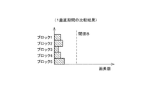
上記のカウントの結果、ブロック毎において閾値Aを超えた画素数は例えば図4に示すものとなる。
【0090】
BL波形制御回路8では、比較結果記憶回路7が記憶するブロック毎の閾値Aを超えた画素数のカウント値Cを調べ、そのカウント値Cが閾値B(B=3072)を超えたブロック、即ち動画存在ブロックを検出し、そのブロックにおいて大きな動画が存在すると判定する(S5)。
【0091】
さらに、BL波形制御回路8では、動画存在ブロックの出現状態、すなわち動画存在ブロックの有無、出現した場合の個数および出現位置等に応じて、インバータ回路9への入力電圧波形および位相を制御する(S6)。
【0092】
図4の例では、第5ブロックのカウント値Cのみが閾値Bを超えており、BL波形制御回路8は、第5ブロックのみが大きな動画物体が存在する動画存在ブロックと判定する。このように動画存在ブロックが検出される状態(ブロックに大きな動画物体が存在する状態)は頻繁に生じる。典型的な例では、テレビ番組の最後に流れる番組スタッフ名・協賛企業名などのスクロール映像である。このスクロール映像は、多くの場合、画面の下部において右から左に高速に流れるように表示され、かつはっきりとした文字の映像であるため、従来の液晶表示装置ではボケた表示が目立っていた。
【0093】
そこで、BL波形制御回路8は、図4に示すように1個のブロックのみが動画存在ブロックである場合には、インバータ回路9の入力電圧波形を図5に示すのように調整する。この場合、バックライト10は、上記パルス波形がハイレベルの期間のみ点灯する。すなわち、図5の例では、インバータ回路9への入力電圧波形が、例えば1垂直期間の40%を発光期間とする(1垂直期間の一部の期間を発行期間とする)パルス波形である場合、そのパルス波形の位相を、パルス波形の立ち下りが第5ブロックへの信号書き込み直前となるように調整している。これにより、ブロック5の画素に表示信号が書き込まれる期間および液晶がそれに応答している期間はバックライト10が発光しなくなる。この結果、擬似輪郭の発生が無くなり、動画表示品位が向上する。
【0094】
なお、第5ブロック以外の第1〜第4ブロックについては静止画であるので、それらブロックにおける表示品位は、それらブロックへの表示信号の書き込みタイミングにおいてバックライト10が点灯しているか消灯しているかによっては影響を受け難い。
【0095】
また、動画存在ブロックが存在する場合の1垂直期間におけるバックライト10の発光期間は上記の40%に限定されない。例えば、動画の表示品位を高めることのみを考えれば発光期間は短いほどよいものの、過度に短くすれば画面が暗くなり過ぎる。したがって、液晶パネル1の輝度の確保も考慮すれば、40〜50%に設定するのが好ましい。この点は、以下の他の例においても同様である。
【0096】
また、本実施の形態においては、バックライト10の点灯期間を1垂直期間において、1期間のみとしている。このようにすることにより、擬似輪郭の発生が防止されている。
【0097】
また、各ブロックへの書き込み期間は、例えば各ブロック含まれる走査線数が同じ場合、ほぼ1垂直期間をブロック数で割った期間となる。
【0098】
図6の例では、全てのブロックにおいてカウント値Cが閾値B以下である。この場合、BL波形制御回路8は、全てのブロックが動画存在ブロックでないと判定し、インバータ回路9に対して次のような制御を行う。なお、このように全てのブロックにおいてカウント値Cが閾値B以下であるのは、全てのブロックの映像を静止画と見なし得る場合である。
【0099】
この場合には、BL波形制御回路8がインバータ回路9への入力電圧波形(バックライト10の点灯)を図5のように制御しても液晶パネル1の表示品位に大きな影響は生じない。ただし、より高い表示品位を得るためには、インバータ回路9への入力電圧波形を図7に示す波形とするのが好ましい。
【0100】
図7に示す波形では、積分値を図5の波形と同じにしているものの、周波数を60Hzから240Hzに変更している。これにより、フリッカを抑制し、かつ静止画の場合の積分輝度を動画存在ブロックが存在する場合(図4、図5)の積分輝度と同じにすることができる。なお、バックライト10を常時点灯させ、かつ図5の場合と同じ積分輝度にしてもよいのは勿論である。
【0101】
さらに、バックライト10を高輝度で常時全点灯にして、静止画の明るさを高くすることも可能である。液晶表示装置はCRTと異なりピーク輝度を得ることは難しいものの、バックライト10を動画と静止画とで異なる輝度に設定することにより、すなわち静止画時にはバックライト10を常時点灯とすることにより、CRTのような鮮やかさが得られるようになる。
【0102】
図8の例では、隣接する2つのブロック、すなわち第4および第5ブロックが閾値Bを超えている。したがって、BL波形制御回路8は第4および第5ブロックを動画存在ブロックと判定する。
【0103】
BL波形制御回路8は、このように連続する2個のブロックが動画存在ブロックである場合、図9に示すように、インバータ回路9への入力電圧のパルス波形の位相を、パルス波形の立ち下りがゲートドライバ3による走査順序において上位にある第4ブロックの画素への信号書き込みの直前となるように調整する。この場合、第5ブロックの最終行の画素に信号を書き込んだ後、バックライト10が起動するまでの時間は、2/5フィールドから1/5フィールドに短縮されるものの、この程度であれば表示品位に問題は生じなかった。
【0104】
図10の例では、連続しない2個のブロック、すなわち第2ブロックと第5ブロックが閾値Bを超えている。図11の例では、全てのブロックが閾値Bを超えている。
【0105】
このように、連続しない複数のブロックが動画存在ブロックである場合、および全てのブロックが動画存在ブロックである場合、BL波形制御回路8は、インバータ回路9への入力電圧に対し、動画存在ブロックが存在しない場合(全てのブロックが静止画である場合)と同様の制御を行う。すなわち、BL波形制御回路8は、インバータ回路9への入力電圧波形を例えば図7に示したものとする。
【0106】
この場合には、液晶表示装置の表示をインパルス化する効果はなくなるものの、バックライト10の点滅と液晶応答とのタイミングが不適切であることによる擬似輪郭は発生しない。図12(a)には、バックライト10の点滅と液晶応答とのタイミングが適切な例(液晶の応答完了時点とインバータ入力波形の立ち上がりとがほぼ合致している場合)、また同図(b)には、同タイミングが不適切な例(液晶の応答完了時点とインバータ入力波形の立ち上がりとが大幅にずれている場合)を示す。
【0107】
なお、本願発明者らが種々の映像について調べた結果、バックライト10を点滅させることによる動画表示品位の向上は、たとえ上記の両タイミングが適切であったとしても、あらゆる映像において得られるとは限らないことが分かった。その理由は映像の撮影条件にある。
【0108】
例えば、映像を撮影したときのカメラのシャッタースピードが1/60sec(開放状態)の場合には、被写体が動いていているとボケて撮影されることになる。よって、元々ボケている映像に対していくらバックライト10の点滅を制御しても(インパルス化を行っても)表示品位の大きな向上効果は望めない。一方、前述のスクロール映像は、文字情報を実映像に合成しているため、文字自体は全くボケていない。このような場合には、バックライト10の点滅を制御すること(インパルス化すること)による動画の表示品位の向上効果は極めて大きいことが分かった。
【0109】
したがって、全体的に動いている動画において、カウント値Cが図11のようになった結果、インパルス化(バックライト10の点滅制御)を停止した場合であっても、シャッタースピードが1/60secであれば、表示品位にはほとんど影響しない。
【0110】
なお、上記の例では、図2に示したように、液晶パネル1の全画素をゲートドライバ3による走査方向に5個のブロックに分割しているが、分割個数についてはこれに限定されることなく、適宜設定すればよい。例えば走査線数に応じて、例えば5〜10の範囲で増減するようにしてもよい。また、分割数は、画面の真中に動画が表示されることが多い場合、奇数とし、画面の真中に1個のブロックが設定されるようにするのが好ましい。
【0111】
図13には、図1の構成に加えてエッジ検出回路(輪郭急峻画像検出手段)11を備えた液晶表示装置を示す。この液晶表示装置では、BL波形制御回路8にて動画存在ブロックと判定されたブロック、すなわち閾値Aを超えた画素数であるカウント数Cが閾値Bを超えているブロックであって、エッジ検出回路11にてエッジの存在が検出されたブロックのみを真の動画存在ブロックと判定するようになっている。そして、この動画存在ブロックの判定結果に基づいて、BL波形制御回路8がインバータ回路9への入力電圧に対する前述の制御、すなわちバックライト10の点灯制御を行うようになっている。
【0112】
上記エッジ検出回路11は、例えば文字認識に使用されるものであり、映像におけるエッジの存在を検出する従来周知の構成である。エッジ検出回路11では、現映像信号内でのデータ比較により、エッジを検出する。
【0113】
ここで、エッジ検出方法および文字認識方法の具体例について説明しておく。
(エッジ検出方法例)
エッジ検出方法としては、例えば、上下、左右、斜めといった隣接画素間の1次差分や2次差分を演算する方法や、ラプラシアン演算を行う方法が挙げられる。さらに、これら手法により抽出された点が、2次元方向(あらゆる方向)の中で、どちらかに連続している集団になっていれば、物体のエッジ(輪郭)を検出できたと判断することができる。
【0114】
なお、エッジ検出は映像信号のノイズに弱く、ノイズ成分までエッジとして検出してしまうため、あらかじめ、信号を平滑化するノイズ除去フィルタを前処理としてかけておくことが望ましい。ただし、実際のエッジまで劣化するためフィルタ処理は最小限にとどめておく必要がある。
(文字認識方法例)
タイトルテロップは、特定の輝度以上、または特定の輝度以下であることが多い。そのため、映像信号の各R、G、Bに対して、あらかじめ決めておいた2つの閾値(Eth1、Eth2)に対して、Eth1以上の点、およびEth2以下の点を抽出した画像を作成する。この画像に対して上記エッジ検出を行う。文字の部分はエッジが線状に形成されている可能性が高く、2次元方向(あらゆる方向)の中でエッジ検出個所が連続している個所を抽出する。この様にして抽出されたエッジのみの画像から文字を探索することにより、文字認識が行うことが可能である。
【0115】
なお、エッジ検出方法や文字認識方法として、上記以外の方法で行ったとしても同様の効果が得られることは言うまでも無い。
【0116】
本液晶表示装置では、動画存在ブロックの判定にさらにブロック内の映像におけるエッジの存在の条件を加えることにより、前述したバックライト10の点灯制御が有効なブロックに対してのみ、その制御を行うようにしている。これにより、無駄な動作を省き、各回路に対する負担を軽減するとともに、応答速度の低下を防止している。
【0117】
ここで、BL波形制御回路8によるバックライト10の点灯制御が有効な動画映像は、前述のように、例えば表示画面の下部において左右に流れる文字のテロップなどのスクロール映像、あるいはコンピュータグラフィックスで描かれた映像である。上記スクロール映像は、予め撮影された映像に後から付加されたものである。
【0118】
一方、バックライト10の点灯制御が有効でない動画映像は、カメラで撮影された時点で元々ぼやけている映像である。このような映像の例としては、例えばマラソンを撮影した映像がある。この映像では、カメラが走者を追っているので走者はほぼ静止画であり、鮮明な映像であるものの、動画となる背景映像はぼやけたものとなっている。
【0119】
さらには、例えば図14に示すように、予め撮影された飛行機の動画映像が第2ブロックに存在し、後から加えられた文字のスクロール映像が第5ブロックに存在するような映像の場合を例としてこの液晶表示装置の利点について説明する。
【0120】
上記映像を例えば図1に示した前記液晶表示装置にて表示する場合、飛行機と文字との何れもが動画と判定される。したがって、第2ブロックと第5ブロックとが動画存在ブロックと判定され、この結果、上記映像信号に対するバックライト10の点灯制御は、図10に示した場合と同様、静止画としての制御が行われる。これにより、第5ブロックの文字のスクロール映像はぼやけた表示となり、高品位の表示を行うことができない。
【0121】
一方、上記映像を図13に示す液晶表示装置にて表示する場合、文字のみが動画と判定される。したがって、第5ブロックのみが動画存在ブロックと判定され、この結果、上記映像信号に対するバックライト10の点灯制御は、図4および図5に示した場合と同様、動画としての制御が行われる。これにより、第5ブロックの文字のスクロール映像については、高品位の動画表示を行うことができる。なお、飛行機の動画映像については、本来、動画用の点灯制御が有効でないものであるため、上記の点灯制御によっても特に影響を受けない。
【0122】
図15には、図1に示した液晶表示装置を、従来周知の液晶高速化回路12を利用して簡単かつ低コストに構成できるようにした例を示す。この液晶高速化回路12は、前記比較回路6に相当する比較回路12aと信号補正回路12bとを備えている。液晶高速化回路12の構成を簡単なブロック図にて示せば図16(a)のようになる。
【0123】
比較回路12bは前記比較回路6と同様、動画画素を検出するための比較を行う。バックライト10の点灯制御においてはこの比較回路12aでの比較結果を利用する。
【0124】
液晶高速化回路12は、ルックアップテーブルを備え、比較回路12aでの比較の結果、動画画素と判定した画素に対して、応答を高速化するため、例えば128という入力値に対してルックアップテーブルを参照して、1f期間だけ、オーバーシュートした例えば160とう値を与える。これにより、図16(b)に示すように、通常応答波形に対して高速化応答波形による応答が行われる。
【0125】
なお、上記液晶高速化回路12については、例えば特開平6−62355号公報において詳細に説明されている。
【0126】
以上のように、本実施の形態の液晶表示装置では、複数の隣接するゲート信号線群を1ブロックとして画面を複数ブロックに分割するとともに、バックライト10の点灯期間を1垂直期間よりも短い期間とし、上記複数のブロックに動画存在ブロックが含まれている場合には、上記点灯期間が、ゲート信号線の走査方向における、動画存在ブロックの直前のブロックにおいて終了するように設定している。これにより、擬似輪郭の発生を抑制しながら、1垂直期間の映像に含まれる動画の表示品位を向上することができる。以下にこの機能についてさらに詳細に説明する。
【0127】
図17には、図4および図5に示した場合に対応する、インバータ回路9への入力電圧波形(バックライト10の点灯タイミング)と信号書き込みによる液晶応答波形との関係を示す。同図では、動画存在ブロックの直前のブロックにおいてバックライト10の点灯期間が終了しており、第5ブロックへの信号書き込みによる液晶の応答の完了タイミングとバックライト10の点灯タイミングとが合致している。したがって、擬似輪郭の発生を抑制しながら、1垂直期間の映像に含まれる動画の表示品位を向上することができる。
【0128】
なお、バックライト10の点灯期間は、上記のように、動画存在ブロックの直前のブロックにおいて終了するのが最良であるものの、これに限定されない。擬似輪郭の抑制機能は低下するもの、例えば、静止画である例えば第2および第3ブロックの期間をバックライト10の点灯期間としても、第5ブロック(動画存在ブロック)の動画表示品位は向上することができる。
【0129】
すなわち、バックライト10の点灯期間が動画存在ブロックへの信号書き込み期間(動画存在ブロックの走査期間)と一致するの最悪の状態であり、それを避ければ、少なくとも最悪の状態よりも動画表示品位を改善することができる。その上で、ブロックの分割数(各ブロックの走査期間)とバックライト10の点灯期間との関係から、表示品位として許容し得るバックライト10の点灯タイミングを設定することも可能である。
【0130】
なお、以上の実施の形態において、動画映像の検出は、画素の階調を比較することにより行っているが、これに限定されることなく、MPEG(Motion Picture Experts Group)等、他の周知の技術を使用して行うことも可能である。例えば、画像メモリ5と比較回路6の代りに、MPEGデコーダの動き検出技術を利用することにより、動画映像の検出を行ってもよい。
【0131】
また、映像信号がそもそもMPEGであれば、映像信号の一部である動きベクトルを活用することもできる。MPEGによる動き検出技術では動きベクトルの大きさによる動きの激しさを検出できるので、とくに動きの激しい個所にバックライトの点灯タイミングを合わせることも可能になり、発明の効果を極大化させることができる。
【0132】
また、例えば先述の第2従来技術では、画面全体の動き量を検出して映像全体が動画か静止画かを検出しているのに対し、本実施の形態の構成では、各ブロック別に動画映像を含むか否かを判定している。したがって、本実施の形態の構成では、バックライト10の点灯制御において、動画映像を含む動画存在ブロックに注目した点灯制御が可能となっている。例えば、予め撮影された動画映像に対して、画面の一部において文字が移動するようなスクロール映像を追加した映像に対して、このスクロール映像を画像のボケを抑制し、鮮明に表示する場合に好適である。
【0133】
また、以上の実施の形態において、BL波形制御回路8は、一つの垂直期間内における動画存在ブロックの出現状態に応じてバックライト10の点灯制御を行う、すなわち変更するようにしている。しかしながら、これに限定されることなく、BL波形制御回路8は、動画存在ブロックの出現状態について同じ結果が複数の垂直期間に渡り連続して生じた場合に、バックライト10に対する点灯制御をその結果に応じたものに変更するようにしてもよい。
【0134】
このような制御を行うことにより、バックライト10に対する点灯制御が頻繁に変更されることによるフリッカの発生を防止することができる。
【0135】
【発明の効果】
以上のように、本発明のバックライト駆動装置は、複数の隣接する走査線群を1ブロックとして前記表示パネルの表示領域を複数のブロックに分割し、前記表示パネルに入力される1垂直期間の画像中における前記ブロック毎の動画の有無を検出する動画検出手段と、前記動画検出手段により動画を含むブロックとして検出された動画存在ブロックの1垂直期間における出現状態に応じて、1垂直期間内における前記バックライトの駆動電圧の波形および位相を調整するバックライト制御手段とを備えている構成である。
【0136】
上記のように、表示パネルの表示領域を複数のブロックに分割し、ブロック毎に動画の有無を検出する構成では、例えば1垂直期間の画像の一部に動画が存在するような場合に、その動画を高品位に表示することについて適切に対応可能となる。すなわち、動画存在ブロックの1垂直期間における種々の出現状態に応じて、バックライトの点灯を例えば輝度ムラを抑制する上で最適な状態に制御することができるので、動画存在ブロックにおける動画の表示を高品位に行うことができる。そして、上記のような処理は、例えばバックライトの点灯タイミングや点灯期間の制御となるから、複雑な回路や構成要素を必要とせず、低コストにて行うことができる。
【0137】
また、本発明のバックライト駆動装置は、複数の隣接する走査線群を1ブロックとして前記表示パネルの表示領域を複数のブロックに分割し、前記表示パネルに入力される1垂直期間の画像中における前記ブロック毎の動画の有無を検出する動画検出手段と、前記表示パネルに入力される1垂直期間の画像中における前記ブロック毎の輪郭が急峻な画像の有無を検出する輪郭急峻画像検出手段と、前記動画検出手段により動画として検出され、かつ輪郭急峻画像検出手段にて輪郭急峻画像として検出された画像を含むブロックである動画存在ブロックの1垂直期間における出現状態に応じて、1垂直期間内における前記バックライトの駆動電圧の波形および位相を調整するバックライト制御手段とを備えている構成である。
【0138】
上記のように、表示パネルの表示領域を複数のブロックに分割し、ブロック毎に動画でありかつ輪郭急峻画像である画像の有無を検出する構成では、例えば1垂直期間の画像の一部に上記画像が存在するような場合に、その画像を高品位に表示することについて適切に対応可能となる。すなわち、動画存在ブロックの1垂直期間における種々の出現状態に応じて、バックライトの点灯を例えば輝度ムラを抑制する上で最適な状態に制御することができるので、動画存在ブロックにおける動画の表示を高品位に行うことができる。そして、上記のような処理は、例えばバックライトの点灯タイミングや点灯期間の制御となるから、複雑な回路や構成要素を必要とせず、低コストにて行うことができる。
【0139】
さらに、バックライトの点灯は、単に動画を含む動画存在ブロックの出現状態ではなく、動画でありかつ輪郭急峻画像である画像を含む動画存在ブロックの出現状態に応じて制御されるので、真に表示品位の改善が可能なブロックに対応したバックライトの点灯制御を行うことができる。これにより、無駄な点灯制御が行われる事態、および本来行われるべき点灯制御が行われずに動画の表示品位が改善されない事態を防止することができる。
【0140】
例えば、動画であっても撮影時のシャッタースピードが遅い場合には、その動画を含む動画存在ブロックの出現状態に応じてバックライトの点灯制御、例えばインパルス化を行うことの効果は小さい。
【0141】
一方、撮影時のシャッタースピードが早い映像は動画個所であっても輪郭(エッジ)が急峻であり、このような動画を含む動画存在ブロックの出現状態に応じてバックライトの点灯制御、例えばインパルス化を行うことは、動画の表示品位の改善効果が大きい。例えば、タイトルテロップが画面下方部で左右にスクロールし、背景も動画の場合、インパルス化の効果があるのは上記の画面下方部のみである。したがって、本発明の構成は、例えば画面の左右にスクロールする文字画像(例えばタイトルテロップ)の表示品位を改善する上で有効である。
【図面の簡単な説明】
【図1】本発明の実施の一形態における液晶表示装置を示すブロック図である。
【図2】図1に示した液晶パネルにおける表示領域を複数のブロックに分割した状態を示す説明図である。
【図3】図1に示した比較回路、比較結果記憶回路およびBL波形制御回路の動作を示すフローチャートである。
【図4】図2に示したブロック毎の動画と判定された画素のカウント値を示すグラフであって、1個のブロックが動画存在ブロックである場合を示すものである。
【図5】図4に示した動画存在ブロックの出現状態に応じたインバータ回路への入力電圧の波形図である。
【図6】図2に示したブロック毎の動画と判定された画素のカウント値を示すグラフの他の例であって、動画存在ブロックがない場合を示すものである。
【図7】図6に示したグラフから判定された、動画存在ブロックがない場合に応じたインバータ回路への入力電圧の波形図である。
【図8】図2に示したブロック毎の動画と判定された画素のカウント値を示すグラフの他の例であって、連続する2個のブロックが動画存在ブロックである場合を示すものである。
【図9】図8に示した動画存在ブロックの出現状態に応じたインバータ回路への入力電圧の波形図である。
【図10】図2に示したブロック毎の動画と判定された画素のカウント値を示すグラフのさらに他の例であって、連続しない2個のブロックが動画存在ブロックである場合を示すものである。
【図11】図2に示したブロック毎の動画と判定された画素のカウント値を示すグラフのさらに他の例であって、全てのブロックが動画存在ブロックである場合を示すものである。
【図12】図12(a)は、バックライトの点滅と液晶応答とのタイミングが適切な場合を示す波形図、図12(b)は、同タイミングが不適切な場合を示す波形図である。
【図13】本発明の実施の他の形態における液晶表示装置を示すブロック図である。
【図14】図13に示した液晶表示装置により適切に対応可能な動画映像を含む映像の例を示す模式図である。
【図15】図1に示した液晶表示装置の他の例を示すブロック図である。
【図16】図16(a)は、図15に示した液晶高速化回路の構成を示す概略のブロック図、図16(b)は、図16(a)に示した信号補正回路の動作を説明する波形図である。
【図17】図4および図5に示した場合に対応する、インバータ回路への入力電圧波形と信号書き込みによる液晶応答波形との関係を示す波形図である。
【符号の説明】
1 液晶パネル(表示パネル)
5 画像メモリ
6 比較回路(動画検出手段)
7 比較結果記憶回路(動画検出手段)
8 BL波形制御回路(動画検出手段、バックライト制御手段)
9 インバータ回路
10 バックライト
11 エッジ検出回路(輪郭急峻画像検出手段)
12 液晶高速化回路
12a 比較回路
12b 信号補正回路[0001]
TECHNICAL FIELD OF THE INVENTION
The present invention relates to a backlight driving device for a display device in which a display method is a hold type, a display device including the same, a liquid crystal television receiver, and a backlight driving method.
[0002]
[Prior art]
Liquid crystal display devices are superior in that they are smaller, lighter and have lower power consumption than CRTs, and are taking the lead role in display devices from CRTs. In the display method, the liquid crystal display device is a hold type, while the CRT is an impulse type.
[0003]
In an impulse-type CRT, an electron beam collides with a phosphor screen to emit light, and each point on the screen is displayed only for a very short time consisting of phosphor afterglow. The CRT displays one frame of video using the afterimage effect of the eyes by sequentially scanning the point emission.
[0004]
On the other hand, in a hold-type liquid crystal display device, display data is written to pixels arranged in a matrix once per frame using a data signal line and a scanning signal line. The written display data is held for one frame in each pixel.
[0005]
The liquid crystal display device is inferior to the CRT in moving image display performance due to the above-described difference in display method from the CRT. This point is described in detail in, for example, "Display Method of Hold-Type Display and Image Quality in Moving Image Display" (written by Yasushi Kurita, The Liquid Crystal Society of Japan, Proceedings of the First LCD Forum, published on August 28, 1998). .
[0006]
That is, in the CRT, the phosphor (screen) is only illuminated instantaneously every field (eg, every 16.7 msec). Will be reflected. On the other hand, in the liquid crystal display device, in the case of the transmissive type, since the backlight is always lit, the pixels to which the bright display data is written are based on the same bright display data for one field period (for example, 16.7 msec period). The display is clear. Therefore, a moving image appears as a blurred image to human eyes. This problem cannot be solved by increasing the response speed of the liquid crystal display device.
[0007]
Therefore, for example, Japanese Patent Application Laid-Open No. 2001-318614 (first prior art) discloses that a backlight is repeatedly turned on and off at a cycle of vertical synchronization, thereby realizing impulse generation in a liquid crystal display device and improving moving image display performance. Technology has been proposed.
[0008]
In this case, the liquid crystal display device performs line-sequential scanning, and one cycle thereof corresponds to the cycle of vertical synchronization. That is, if the backlight is simply turned on and off, the timing at which the backlight is turned on and off, and the timing at which the signal is written to the pixels differ depending on the location, resulting in a reduction in display quality such as generation of false contours.
[0009]
Therefore, in the same publication, in order to eliminate the mismatch between the timings, the plurality of cold cathode tubes of the direct-type backlight are blinked individually and sequentially, and the backlight itself is scanned according to the line-sequential scanning of the liquid crystal display device. In this way, the timing of turning on the backlight and the timing of writing the signal to the pixel are matched.
[0010]
Japanese Patent Application Laid-Open No. 2002-287700 (second prior art) discloses, like the first prior art, that the backlight is turned on in one field in order to prevent the deterioration of the moving image display performance due to the constant lighting of the backlight. Time limiting techniques have been proposed. Specifically, the display signal is written to the data signal line in a state where the backlight is turned off in the first half of the vertical synchronization by shortening the signal writing time, and the backlight is written in the second half after the writing of the display signal is completed. A technique of lighting is proposed.
[0011]
[Patent Document 1]
JP 2001-318614 A (published November 10, 2001)
[0012]
[Patent Document 2]
JP 2002-287700 A (publication date: October 4, 2002)
[0013]
[Patent Document 3]
JP-A-6-62355 (publication date: March 4, 1994)
[0014]
[Non-patent document 1]
Yasushi Kurita, "Display Method of Hold-Type Display and Image Quality in Moving Image Display" Published by the Liquid Crystal Society of Japan, August 28, 1998
[0015]
[Problems to be solved by the invention]
However, the first related art has a problem that luminance unevenness occurs first. That is, in the first conventional technique, among the plurality of fluorescent lamps constituting the backlight, the light of the fluorescent lamp to be turned on is not illuminated to pixels other than the pixel corresponding to the fluorescent lamp. It is necessary to provide a partition plate. However, when the partition plate is reflected on the screen, luminance unevenness occurs. As a result, new problems such as an increase in the number of components and occurrence of display unevenness (luminance unevenness) are caused.
[0016]
When a scattering sheet is added, for example, to reduce the luminance unevenness, light spills over the partition plate to another region, and the effect of providing the partition plate is reduced. As a result, the moving image display performance deteriorates, and desired performance cannot be obtained by providing the partition plate.
[0017]
Second, in order to independently control the flashing of each fluorescent lamp, an inverter circuit and a pulse light emitting circuit corresponding to the number of fluorescent lamps are required. As a result, the circuit configuration becomes complicated and the cost is increased.
[0018]
Thirdly, in principle, the backlight is limited to the direct type, which causes a disadvantage that the number of lamps is small and the edge light type used in small and medium-sized liquid crystal displays cannot be applied.
[0019]
On the other hand, in the second conventional technique, a signal writing period is shortened in comparison with a configuration in which a display signal is written to each pixel using one field period. It is necessary to shorten the signal writing time. However, if the writing time is simply shortened, the writing of the signal to each pixel becomes insufficient, that is, charging failure occurs, and the display quality deteriorates. To prevent this, it is necessary to modify all the electrical characteristics of the data signal line, the scanning signal line and the TFT.
[0020]
Further, since the data signal line and the gate signal line have a signal delay due to electric resistance and capacitance, it is practically difficult to reduce the writing time. In particular, it is disadvantageous in a large liquid crystal display device or a liquid crystal display device for HDTV having a large number of pixels.
[0021]
In addition, in order to reduce the time for writing a display signal to a pixel, it is necessary to reduce the on-resistance of a TFT serving as a switching element. In this case, it is necessary to increase the size of the TFT, and as a result, the aperture ratio (transmittance) decreases.
[0022]
Therefore, the liquid crystal display device of the present invention is a backlight driving device capable of displaying moving images with high quality while suppressing luminance unevenness and cost increase, a display device including the same, a liquid crystal television receiver, and a backlight driving device. It is intended to provide a method.
[0023]
[Means for Solving the Problems]
In order to solve the above problem, a backlight driving device of the present invention has a plurality of scanning lines arranged in one direction, and these scanning lines are sequentially scanned, and a display signal is written to a pixel corresponding to each scanning line. In a backlight driving device for driving a backlight of a display panel, a plurality of adjacent scanning line groups are taken as one block to divide the display area of the display panel into a plurality of blocks, and one vertical period inputted to the display panel is provided. A moving image detecting means for detecting the presence or absence of a moving image for each block in the image, and a moving image present block detected as a block including a moving image by the moving image detecting means within one vertical period according to an appearance state in one vertical period. And backlight control means for adjusting the waveform and phase of the backlight drive voltage.
[0024]
Further, the backlight driving method of the present invention has a plurality of scanning lines arranged in one direction, and the scanning lines are sequentially scanned, and a display signal is written to a pixel corresponding to each scanning line. In the method, a display area of the display panel is divided into a plurality of blocks by using a plurality of adjacent scanning line groups as one block, and the presence or absence of a moving image for each block in an image of one vertical period input to the display panel is determined. A first step of detecting, and a waveform of the driving voltage of the backlight in one vertical period according to an appearance state of the moving image existence block detected as a block including the moving image in the first step in one vertical period; And a second step of adjusting the phase.
[0025]
According to the above configuration, the backlight drive unit controls the driving voltage of the backlight within one vertical period in accordance with the appearance state of the moving image existence block detected as a block including the moving image by the moving image detection unit in one vertical period. Are adjusted.
[0026]
As described above, in the configuration in which the display area of the display panel is divided into a plurality of blocks and the presence or absence of a moving image is detected for each block, for example, when a moving image exists in a part of an image in one vertical period, the moving image Can be appropriately dealt with for displaying high quality. That is, according to various appearance states of the moving image existence block in one vertical period, lighting of the backlight can be controlled to an optimal state for suppressing, for example, luminance unevenness. It can be performed with high quality. The above-described processing is, for example, control of the lighting timing and the lighting period of the backlight. Therefore, the processing can be performed at low cost without requiring complicated circuits and components.
[0027]
A backlight driving device of the present invention has a plurality of scanning lines arranged in one direction, and drives the backlight of a display panel in which the scanning lines are sequentially scanned and a display signal is written to a pixel corresponding to each scanning line. In the backlight driving device, the display area of the display panel is divided into a plurality of blocks by using a plurality of adjacent scanning line groups as one block, and a moving image of each block in an image of one vertical period input to the display panel is provided. Moving image detecting means for detecting the presence / absence of an image, contour sharp image detecting means for detecting the presence or absence of an image having a sharp outline for each block in an image of one vertical period input to the display panel, and the moving image detecting means One vertical line of the moving image existing block, which is a block that includes an image that is detected as a moving image and that is detected as a sharp outline image by the sharp outline image detecting unit. Depending on the occurrence state between, it is characterized by comprising a backlight control means for adjusting the waveform and phase of the drive voltage of the backlight within a single vertical period.
[0028]
Further, the backlight driving method of the present invention has a plurality of scanning lines arranged in one direction, and the scanning lines are sequentially scanned, and a display signal is written to a pixel corresponding to each scanning line. In the method, a display area of the display panel is divided into a plurality of blocks by using a plurality of adjacent scanning line groups as one block, and the presence or absence of a moving image for each block in an image of one vertical period input to the display panel is determined. A first step of detecting, a second step of detecting the presence or absence of an image having a sharp outline for each block in an image of one vertical period input to the display panel, and a moving image in the first step. In accordance with the appearance state in one vertical period of the moving image existence block which is a block including the image detected and detected as the sharp outline image in the second step, It is characterized in that it comprises a second step of adjusting the waveform and phase of the drive voltage of the backlight in the vertical period.
[0029]
According to the above configuration, the backlight control means controls the backlight in one vertical period according to the appearance state of the moving image existence block, which is a block including an image that is a moving image and an image with sharp edges, in one vertical period. The waveform and phase of the drive voltage are adjusted.
[0030]
As described above, in the configuration in which the display area of the display panel is divided into a plurality of blocks, and the presence or absence of an image that is a moving image and a sharp outline image is detected for each block, for example, the image is included in a part of the image in one vertical period. In such a case, it is possible to appropriately cope with displaying the image with high quality. That is, according to various appearance states of the moving image existence block in one vertical period, lighting of the backlight can be controlled to an optimal state for suppressing, for example, luminance unevenness. It can be performed with high quality. The above-described processing is, for example, control of the lighting timing and the lighting period of the backlight. Therefore, the processing can be performed at low cost without requiring complicated circuits and components.
[0031]
Furthermore, since the lighting of the backlight is controlled not according to the appearance state of the moving image existence block including the moving image but to the appearance state of the moving image existence block including the image that is the moving image and the image having the sharp outline, the backlight is truly displayed. It is possible to perform lighting control of a backlight corresponding to a block whose quality can be improved. Accordingly, it is possible to prevent a situation in which useless lighting control is performed and a situation in which the display quality of a moving image is not improved because the lighting control that should be performed is not performed.
[0032]
For example, if the shutter speed at the time of shooting is slow even for a moving image, the effect of performing backlight lighting control, for example, performing impulse conversion according to the appearance state of the moving image existence block including the moving image is small.
[0033]
On the other hand, an image with a fast shutter speed at the time of shooting has a sharp outline (edge) even at a moving image portion, and the backlight is controlled in accordance with the appearance state of a moving image existence block including such a moving image, for example, impulse generation. Is effective in improving the display quality of the moving image. For example, when the title telop scrolls left and right at the lower part of the screen and the background is also a moving image, only the lower part of the screen has the effect of impulse conversion. Therefore, the configuration of the present invention is effective, for example, in improving the display quality of a character image (for example, a title telop) scrolling left and right on the screen.
[0034]
In the above backlight driving device, the moving image detecting means detects the presence or absence of a moving image by comparing a total value of the number of moving image pixels included in each block with a threshold, and sets the threshold to a total value of the number of moving image pixels. May be changed according to the total value of the number of moving picture pixels in the block having the maximum value.
[0035]
According to the above configuration, the threshold value for detecting the presence or absence of a moving image is changed according to the total value of the moving image pixels in the block having the maximum value of the total number of moving image pixels. , Even if the moving image is small, the moving image can be appropriately detected, and the display quality of the moving image can be improved.
[0036]
In the above backlight driving device, the moving image detecting means may set the threshold value to a value obtained by dividing the total value of the moving image pixels in a block having the maximum value of the moving image pixels by 1 / n (n is a positive value). (Integer).
[0037]
According to the above configuration, the logic of the moving image detection unit becomes extremely simple, and the circuit configuration can be simplified.
[0038]
In the backlight driving device described above, the backlight control unit turns on the backlight from a timing at which a response for display by writing display data to the moving image existing block, for example, a response of the display element is almost completed. The adjustment may be made as follows.
[0039]
According to the above configuration, since the backlight is turned on at the timing when the response for display by writing the display data to the moving image existing block is almost completed, it is possible to prevent the occurrence of luminance unevenness.
[0040]
In the backlight driving device described above, the backlight control unit may be configured to adjust so that the backlight is turned off at a timing when writing of display data to the moving image existing block is started.
[0041]
According to the above configuration, since the backlight is turned off at the timing when the writing of the display data to the moving image existing block is started, it is possible to prevent the occurrence of luminance unevenness.
[0042]
In the backlight driving device described above, the moving image present block may be configured such that only one block of all blocks is a moving image present block.
[0043]
According to the above configuration, when only one block of all blocks is a moving image existing block, the backlight is turned on for the moving image existing block, for example, from the timing when the response of the display element is almost completed. The display device can be appropriately adjusted, and the display device can be appropriately made into an impulse with respect to such an appearance state of the moving image existence block.
[0044]
In the backlight driving device described above, the moving image existence block may be configured such that a plurality of blocks among all blocks are moving image existence blocks and are continuous.
[0045]
According to the configuration described above, when a plurality of blocks among all blocks are moving image existing blocks and they are continuous, for example, the response to the moving image existing blocks is started from the timing when the response of the display element is almost completed. It is possible to appropriately adjust so that the light is turned on, and to appropriately impulse the display device with respect to such an appearance state of the moving image existence block.
[0046]
In the above backlight driving device, the backlight control means may be configured to adjust so that the backlight is always turned on when none of the blocks is a moving image existing block.
[0047]
In the above backlight driving device, the backlight control means may be configured to adjust the flickering frequency of the backlight to be higher when none of the blocks is a moving image present block.
[0048]
According to the above configuration, all the images in one vertical period are still images, and in this case, the flickering frequency of the backlight increases, so that the occurrence of flicker can be suppressed. The degree to which the lighting frequency is increased is preferably at least twice the vertical synchronization frequency, more preferably about four times.
[0049]
In addition, for example, when only one moving image present block exists, if the display device is impulse-lit by turning on the backlight only during a part of one vertical period, the integrated luminance decreases. Therefore, in order to match the integrated luminance at this time with the integrated luminance at the time of a still image, when all the images in one vertical period are still images, the lighting period of one backlight is shortened, and Increase the pulse frequency of For example, it blinks at 240 Hz. Thus, the hold mode display is performed on the display device.
[0050]
In the above backlight driving device, the backlight control means may be configured to adjust so that the backlight is always turned on when all the blocks are moving image existing blocks.
[0051]
According to the above configuration, the backlight is always turned on when all the blocks are moving image existing blocks, so that the occurrence of a pseudo contour can be suppressed. That is, when all the blocks are moving image existing blocks, it is not possible to control the lighting of the backlight to make the display device impulse. Therefore, the backlight is turned on for one vertical period and the display device is displayed by the hold method.
[0052]
In the backlight driving device described above, the backlight control unit may be configured to adjust the backlight blinking frequency to be higher when all blocks are moving image existing blocks.
[0053]
According to the above configuration, all the images in one vertical period are moving images, and in this case, the flickering frequency of the backlight increases, so that the occurrence of flicker can be suppressed. The degree to which the lighting frequency is increased is preferably at least twice the vertical synchronization frequency, more preferably about four times.
[0054]
In addition, for example, when only one moving image present block exists, if the display device is impulse-lit by turning on the backlight only during a part of one vertical period, the integrated luminance decreases. Therefore, in order to match this integrated luminance with the integrated luminance when all blocks are moving image existing blocks, when all the blocks are moving image existing blocks, the lighting period of one backlight is shortened, and Increase the backlight pulse frequency. For example, it blinks at 240 Hz. Thus, the hold mode display is performed on the display device.
[0055]
In the above backlight driving device, the backlight control means may be configured to adjust so that the backlight is always turned on when a plurality of discontinuous blocks are moving image existing blocks.
[0056]
According to the above configuration, when a plurality of non-consecutive blocks are moving image existing blocks, the backlight is always turned on. This can prevent the occurrence of false contours. Further, it is preferable that the brightness of the screen is increased by constantly turning on the backlight.
[0057]
In the above backlight drive device, the backlight control means may be configured to adjust the backlight blinking frequency to be higher when a plurality of discontinuous blocks are moving image existing blocks.
[0058]
According to the above configuration, the flickering frequency of the backlight increases, so that flicker can be suppressed.
[0059]
In the above backlight driving device, the backlight control unit may be configured such that when the same appearance state of a moving image existence block in one vertical period occurs over a plurality of vertical periods, the backlight in one vertical period The configuration may be such that the waveform and phase of the drive voltage are adjusted.
[0060]
According to the above configuration, the change of the lighting state with the back line is performed gently, so that it is possible to suppress a situation in which the lighting state of the backlight is frequently changed and is recognized as a screen flicker.
[0061]
In the above backlight driving device, the moving image detecting means may be configured to detect the presence or absence of a moving image for each block by comparing an image signal of a current frame with an image signal of a frame immediately before the current frame. .
[0062]
According to the above configuration, it is possible to support a progressive display device.
[0063]
In the above backlight drive device, the moving image detecting means may be configured to compare the image signal of the current field with the image signal of the field immediately before the current field to detect the presence or absence of the moving image for each block. .
[0064]
According to the above configuration, it is possible to cope with the display device of the interlace system. In the interlace system, the pixels of the current field correspond to the pixels of the field before the previous field, so that the presence or absence of a moving image can be accurately detected.
[0065]
In the above backlight driving device, the moving image detecting means may be configured to compare the image signal of the current field with the image signal of the field immediately before the current field to detect the presence or absence of the moving image for each block. .
[0066]
According to the above configuration, for example, in an interlaced display device, it is also possible to detect the presence or absence of a moving image for each block by comparing the image signal of the current field with the image signal of the field immediately before the current field. In this case, the storage capacity required for the image memory can be reduced by half as compared with the case where the image signal of the current field is compared with the image signal of the field immediately before the current field.
[0067]
In the above backlight driving device, the moving image detecting means obtains a difference in gradation data for each pixel of an image signal to be compared, and calculates a total value of the number of moving image pixels in which the difference is larger than a first threshold value as a second value. It may be configured to detect the presence or absence of a moving image by comparing with the threshold value.
[0068]
According to the above configuration, the configuration is the same as the configuration for counting the number of pixels for which the OS is turned on in the OS drive, and the moving image detecting means can be configured by adding a small logic circuit to the OS drive.
[0069]
In the backlight driving device described above, the sharp outline image detecting means may detect a character image.
[0070]
According to the above configuration, for example, for an image obtained by adding a character scroll image (for example, a title telop) as a moving image to a previously captured image, the character scroll image is appropriately detected as a moving image, and the display quality is determined. Can be improved.
[0071]
A display device according to the present invention includes any one of the backlight driving devices described above.
[0072]
The above-described display device includes a comparison circuit that compares pixel gradation data in order to detect a moving image, and detects a moving image pixel based on a comparison result of the comparison circuit, and speeds up display response to the moving image pixel. A moving image detecting means for detecting the presence or absence of a moving image using a comparison result of a comparing circuit in the display speed-up circuit. Is also good.
[0073]
According to the above configuration, the moving image detection unit uses the comparison result of the comparison circuit in the well-known display speed-up circuit provided in the liquid crystal display device, for example, so that the configuration can be simplified.
[0074]
A liquid crystal television receiver according to the present invention is configured to include any one of the display devices described above.
[0075]
BEST MODE FOR CARRYING OUT THE INVENTION
An embodiment of the present invention will be described below with reference to the drawings.
FIG. 1 shows a block diagram of the liquid crystal display device of the present embodiment. As shown in FIG. 1, the liquid crystal display device includes a liquid crystal panel (display panel) 1, a
[0076]
The
[0077]
The
[0078]
The
[0079]
The comparison circuit 6 compares the current video signal for each pixel with the video signal before one vertical synchronization stored in the image memory 5 (hereinafter referred to as a previous video signal), and determines whether the current video signal is a moving image and a still image. It is determined which one is. Here, the difference between the signal (digital signal value indicating the gradation number from 0 to 255) as the threshold value A (first threshold value) is, for example, 8, and the difference between the current video signal and the previous video signal exceeds 8. It is determined on a pixel-by-pixel basis. When the difference exceeds 8, the pixel is determined as a moving image pixel, and when the difference is less than 8, the pixel is determined as a still image pixel. Here, each of the RGB signals is compared separately, and when the difference of at least one of the three signals exceeds the threshold A, the pixel is determined as a moving image pixel.
[0080]
Further, the value of 8 in the threshold value A is not limited to this, and is preferably adjusted as appropriate. That is, when the noise component is small in the input video signal, the threshold value A can be set smaller. On the other hand, when there are many noise components, even if it is a still image, the signal difference may be large, resulting in erroneous determination. Therefore, the threshold value A is set to be relatively large. In addition, for example, the magnitude of noise varies depending on the video signal source, such as when the radio wave condition is poor, analog video, video signals for games, and DVD video signals. Therefore, it is preferable that the threshold value A is appropriately set according to the video signal source.
[0081]
As shown in FIG. 2, the comparison
[0082]
The BL
[0083]
Further, the BL
[0084]
The
[0085]
In the above configuration, the video signal input to the liquid crystal display device is provided to the
[0086]
On the other hand, each unit from the
[0087]
The comparison circuit 6 compares the input current video signal with the video signal before one vertical synchronization stored in the
[0088]
The comparison
[0089]
As a result of the above counting, the number of pixels exceeding the threshold value A for each block is as shown in FIG. 4, for example.
[0090]
The BL
[0091]
Further, the BL
[0092]
In the example of FIG. 4, only the count value C of the fifth block exceeds the threshold B, and the BL
[0093]
Therefore, when only one block is a moving image existing block as shown in FIG. 4, the BL
[0094]
Since the first to fourth blocks other than the fifth block are still images, the display quality in those blocks depends on whether the
[0095]
In addition, the emission period of the
[0096]
Further, in the present embodiment, the lighting period of the
[0097]
In addition, for example, when the number of scanning lines included in each block is the same, the writing period for each block is a period obtained by dividing substantially one vertical period by the number of blocks.
[0098]
In the example of FIG. 6, the count value C is equal to or smaller than the threshold value B in all the blocks. In this case, the BL
[0099]
In this case, even if the BL
[0100]
In the waveform shown in FIG. 7, the integrated value is the same as the waveform in FIG. 5, but the frequency is changed from 60 Hz to 240 Hz. Thus, flicker can be suppressed, and the integrated luminance in the case of a still image can be made the same as the integrated luminance in the case where a moving image existence block exists (FIGS. 4 and 5). It is needless to say that the
[0101]
Further, it is also possible to always turn on the
[0102]
In the example of FIG. 8, two adjacent blocks, that is, the fourth and fifth blocks exceed the threshold B. Therefore, the BL
[0103]
When the two consecutive blocks are moving image present blocks, the BL
[0104]
In the example of FIG. 10, two discontinuous blocks, that is, the second block and the fifth block exceed the threshold B. In the example of FIG. 11, all blocks exceed the threshold B.
[0105]
As described above, when a plurality of discontinuous blocks are moving image existing blocks, and when all blocks are moving image existing blocks, the BL
[0106]
In this case, although the effect of making the display of the liquid crystal display device into an impulse disappears, a false contour due to improper timing of the blinking of the
[0107]
In addition, as a result of examining various images by the inventors of the present application, improvement in moving image display quality by blinking the
[0108]
For example, when the shutter speed of the camera at the time of capturing an image is 1/60 sec (open state), the image is blurred when the subject is moving. Therefore, no matter how much the blinking of the
[0109]
Therefore, even if the impulse generation (blinking control of the backlight 10) is stopped as a result of the count value C being as shown in FIG. 11 in the moving image that is moving as a whole, the shutter speed remains at 1/60 sec. If it does, it hardly affects the display quality.
[0110]
In the above example, as shown in FIG. 2, all the pixels of the
[0111]
FIG. 13 shows a liquid crystal display device provided with an edge detection circuit (steep-contour image detection means) 11 in addition to the configuration of FIG. In this liquid crystal display device, the BL
[0112]
The
[0113]
Here, specific examples of the edge detection method and the character recognition method will be described.
(Example of edge detection method)
Examples of the edge detection method include a method of calculating a primary difference and a secondary difference between adjacent pixels such as up, down, left, right, and oblique, and a method of performing Laplacian calculation. Further, if the points extracted by these methods are in a continuous group in either of the two-dimensional directions (all directions), it can be determined that the edge (contour) of the object has been detected. it can.
[0114]
Since edge detection is weak to noise of a video signal and even a noise component is detected as an edge, it is desirable to apply a noise removal filter for smoothing the signal in advance as preprocessing. However, it is necessary to keep the filtering process to a minimum because the actual edge is deteriorated.
(Example of character recognition method)
Title telops are often at or above a specific luminance or below a specific luminance. Therefore, for each of R, G, and B of the video signal, an image is generated by extracting points equal to or larger than Eth1 and equal to or smaller than Eth2 for two predetermined thresholds (Eth1, Eth2). The edge detection is performed on this image. There is a high possibility that the edge of the character portion is formed in a linear shape, and a portion where edge detection portions are continuous in a two-dimensional direction (any direction) is extracted. By retrieving characters from the image of only the edges extracted in this manner, character recognition can be performed.
[0115]
It goes without saying that the same effect can be obtained even if the edge detection method or the character recognition method is performed by a method other than the above.
[0116]
In the present liquid crystal display device, by adding a condition of the presence of an edge in the video in the block to the determination of the moving image presence block, the control is performed only on the block for which the lighting control of the
[0117]
Here, as described above, the moving image image for which the backlight control of the
[0118]
On the other hand, the moving image video for which the lighting control of the
[0119]
Further, for example, as shown in FIG. 14, a video image in which a moving image image of an airplane previously captured exists in the second block and a scroll image of a character added later exists in the fifth block is exemplified. The advantages of this liquid crystal display device will be described.
[0120]
For example, when the video is displayed on the liquid crystal display device shown in FIG. 1, both the airplane and the characters are determined to be moving images. Therefore, the second block and the fifth block are determined to be moving image existing blocks. As a result, the lighting control of the
[0121]
On the other hand, when the video is displayed on the liquid crystal display device shown in FIG. 13, only characters are determined to be moving images. Therefore, only the fifth block is determined to be a moving image existing block. As a result, the lighting control of the
[0122]
FIG. 15 shows an example in which the liquid crystal display device shown in FIG. 1 can be configured simply and at low cost by using a conventionally known liquid crystal speed-
[0123]
Similar to the comparison circuit 6, the
[0124]
The liquid crystal speed-
[0125]
The liquid crystal speed-
[0126]
As described above, in the liquid crystal display device of the present embodiment, the screen is divided into a plurality of blocks by using a plurality of adjacent gate signal line groups as one block, and the lighting period of the
[0127]
FIG. 17 shows the relationship between the input voltage waveform (turn-on timing of the backlight 10) to the
[0128]
The lighting period of the
[0129]
In other words, the worst state in which the lighting period of the
[0130]
In the above embodiment, the detection of the moving image is performed by comparing the gray levels of the pixels. However, the present invention is not limited to this, and other well-known methods such as MPEG (Motion Picture Experts Group) are used. It is also possible to do this using technology. For example, instead of the
[0131]
If the video signal is MPEG in the first place, a motion vector which is a part of the video signal can be used. With the motion detection technology based on MPEG, the intensity of the motion due to the magnitude of the motion vector can be detected, so that the backlight lighting timing can be adjusted to a location where the motion is particularly severe, and the effect of the invention can be maximized. .
[0132]
Also, for example, in the above-described second related art, the amount of motion of the entire screen is detected to detect whether the entire video is a moving image or a still image, whereas in the configuration of the present embodiment, the moving image Is determined. Therefore, in the configuration of the present embodiment, in the lighting control of the
[0133]
In the above embodiment, the BL
[0134]
By performing such control, it is possible to prevent occurrence of flicker due to frequent changes in the lighting control for the
[0135]
【The invention's effect】
As described above, the backlight driving device according to the present invention divides the display area of the display panel into a plurality of blocks by using a plurality of adjacent scanning line groups as one block, and performs one vertical period input to the display panel. A moving image detecting means for detecting the presence or absence of a moving image for each block in an image, and a moving image present block detected as a block including a moving image by the moving image detecting means in one vertical period according to an appearance state in one vertical period. A backlight control unit that adjusts the waveform and phase of the backlight drive voltage.
[0136]
As described above, in the configuration in which the display area of the display panel is divided into a plurality of blocks and the presence or absence of a moving image is detected for each block, for example, when a moving image exists in a part of the image in one vertical period, the It is possible to appropriately cope with displaying a moving image with high quality. That is, according to various appearance states of the moving image existence block in one vertical period, lighting of the backlight can be controlled to an optimal state for suppressing, for example, luminance unevenness. It can be performed with high quality. The above-described processing is, for example, control of the lighting timing and the lighting period of the backlight. Therefore, the processing can be performed at low cost without requiring complicated circuits and components.
[0137]
Further, the backlight driving device of the present invention divides the display area of the display panel into a plurality of blocks by using a plurality of adjacent scanning line groups as one block, and outputs the divided image data in one vertical period image input to the display panel. Moving image detecting means for detecting the presence or absence of a moving image for each block; contour sharp image detecting means for detecting the presence or absence of a sharp image for each block in an image of one vertical period input to the display panel; According to the appearance state in one vertical period of a moving image existence block, which is a block including an image detected as a moving image by the moving image detection unit and detected as a sharp outline image by the sharp outline image detection unit, within one vertical period A backlight control unit that adjusts the waveform and phase of the backlight drive voltage.
[0138]
As described above, in the configuration in which the display area of the display panel is divided into a plurality of blocks and the presence or absence of an image that is a moving image and a sharp outline image is detected for each block, for example, a part of the image in one vertical period When an image exists, it is possible to appropriately cope with displaying the image with high quality. That is, according to various appearance states of the moving image existence block in one vertical period, lighting of the backlight can be controlled to an optimal state for suppressing, for example, luminance unevenness. It can be performed with high quality. The above-described processing is, for example, control of the lighting timing and the lighting period of the backlight. Therefore, the processing can be performed at low cost without requiring complicated circuits and components.
[0139]
Furthermore, since the lighting of the backlight is controlled not according to the appearance state of the moving image existence block including the moving image but to the appearance state of the moving image existence block including the image that is the moving image and the image having the sharp outline, the backlight is truly displayed. It is possible to perform lighting control of a backlight corresponding to a block whose quality can be improved. Accordingly, it is possible to prevent a situation in which useless lighting control is performed and a situation in which the display quality of a moving image is not improved because the lighting control that should be performed is not performed.
[0140]
For example, if the shutter speed at the time of shooting is slow even for a moving image, the effect of performing backlight lighting control, for example, performing impulse conversion according to the appearance state of the moving image existence block including the moving image is small.
[0141]
On the other hand, an image with a fast shutter speed at the time of shooting has a sharp outline (edge) even at a moving image portion, and the backlight is controlled in accordance with the appearance state of a moving image existence block including such a moving image, for example, impulse generation. Is effective in improving the display quality of the moving image. For example, when the title telop scrolls left and right at the lower part of the screen and the background is also a moving image, only the lower part of the screen has the effect of impulse conversion. Therefore, the configuration of the present invention is effective, for example, in improving the display quality of a character image (for example, a title telop) scrolling left and right on the screen.
[Brief description of the drawings]
FIG. 1 is a block diagram illustrating a liquid crystal display device according to an embodiment of the present invention.
FIG. 2 is an explanatory diagram showing a state where a display area in the liquid crystal panel shown in FIG. 1 is divided into a plurality of blocks.
FIG. 3 is a flowchart illustrating operations of a comparison circuit, a comparison result storage circuit, and a BL waveform control circuit illustrated in FIG. 1;
FIG. 4 is a graph showing count values of pixels determined to be a moving image for each block shown in FIG. 2, showing a case where one block is a moving image existing block;
5 is a waveform diagram of an input voltage to an inverter circuit according to an appearance state of a moving image existence block illustrated in FIG. 4;
FIG. 6 is another example of a graph showing a count value of a pixel determined to be a moving image for each block shown in FIG. 2, in a case where there is no moving image existing block;
FIG. 7 is a waveform diagram of an input voltage to the inverter circuit according to a case where there is no moving image existing block, determined from the graph shown in FIG. 6;
8 is another example of the graph showing the count value of the pixel determined to be a moving image for each block shown in FIG. 2, in which two continuous blocks are moving image existing blocks. .
9 is a waveform diagram of the input voltage to the inverter circuit according to the appearance state of the moving image existence block shown in FIG. 8;
10 is still another example of the graph showing the count value of pixels determined to be a moving image for each block shown in FIG. 2, in which two discontinuous blocks are moving image existing blocks. is there.
FIG. 11 is still another example of the graph showing the count value of the pixel determined as a moving image for each block shown in FIG. 2, in which all blocks are moving image existing blocks.
FIG. 12A is a waveform chart showing a case where the timing of the blinking of the backlight and the liquid crystal response is appropriate, and FIG. 12B is a waveform chart showing a case where the timing is inappropriate. .
FIG. 13 is a block diagram showing a liquid crystal display device according to another embodiment of the present invention.
FIG. 14 is a schematic diagram illustrating an example of a video including a moving image that can be appropriately handled by the liquid crystal display device illustrated in FIG. 13;
15 is a block diagram showing another example of the liquid crystal display device shown in FIG.
16 (a) is a schematic block diagram showing a configuration of the liquid crystal speed-up circuit shown in FIG. 15, and FIG. 16 (b) shows an operation of the signal correction circuit shown in FIG. 16 (a). FIG. 4 is a waveform diagram for explaining.
FIG. 17 is a waveform diagram showing a relationship between an input voltage waveform to an inverter circuit and a liquid crystal response waveform due to signal writing corresponding to the cases shown in FIGS. 4 and 5;
[Explanation of symbols]
1 liquid crystal panel (display panel)
5 Image memory
6. Comparison circuit (moving image detection means)
7 Comparison result storage circuit (moving image detection means)
8 BL waveform control circuit (moving image detection means, backlight control means)
9 Inverter circuit
10 Backlight
11 Edge detection circuit (steep contour image detection means)
12 LCD speed-up circuit
12a Comparison circuit
12b signal correction circuit
Claims (25)
複数の隣接する走査線群を1ブロックとして前記表示パネルの表示領域を複数のブロックに分割し、前記表示パネルに入力される1垂直期間の画像中における前記ブロック毎の動画の有無を検出する動画検出手段と、
前記動画検出手段により動画を含むブロックとして検出された動画存在ブロックの1垂直期間における出現状態に応じて、1垂直期間内における前記バックライトの駆動電圧の波形および位相を調整するバックライト制御手段とを備えていることを特徴とするバックライト駆動装置。In a backlight driving device which has a plurality of scanning lines arranged in one direction and drives a backlight of a display panel in which these scanning lines are sequentially scanned and a display signal is written to a pixel corresponding to each scanning line,
A moving image in which the display area of the display panel is divided into a plurality of blocks by using a plurality of adjacent scanning line groups as one block, and the presence or absence of the moving image of each block in an image of one vertical period input to the display panel is detected. Detecting means;
Backlight control means for adjusting the waveform and phase of the drive voltage of the backlight within one vertical period according to the appearance state of the moving image existence block detected as a block including a moving image by the moving image detection means during one vertical period; A backlight driving device comprising:
複数の隣接する走査線群を1ブロックとして前記表示パネルの表示領域を複数のブロックに分割し、前記表示パネルに入力される1垂直期間の画像中における前記ブロック毎の動画の有無を検出する動画検出手段と、
前記表示パネルに入力される1垂直期間の画像中における前記ブロック毎の輪郭が急峻な画像の有無を検出する輪郭急峻画像検出手段と、
前記動画検出手段により動画として検出され、かつ輪郭急峻画像検出手段にて輪郭急峻画像として検出された画像を含むブロックである動画存在ブロックの1垂直期間における出現状態に応じて、1垂直期間内における前記バックライトの駆動電圧の波形および位相を調整するバックライト制御手段とを備えていることを特徴とするバックライト駆動装置。In a backlight driving device which has a plurality of scanning lines arranged in one direction and drives a backlight of a display panel in which these scanning lines are sequentially scanned and a display signal is written to a pixel corresponding to each scanning line,
A moving image in which the display area of the display panel is divided into a plurality of blocks by using a plurality of adjacent scanning line groups as one block, and the presence or absence of the moving image of each block in an image of one vertical period input to the display panel is detected. Detecting means;
Contour sharp image detecting means for detecting the presence or absence of an image having a sharp contour for each block in an image of one vertical period input to the display panel;
According to the appearance state in one vertical period of a moving image existence block, which is a block including an image detected as a moving image by the moving image detection unit and detected as a sharp outline image by the sharp outline image detection unit, within one vertical period A backlight control unit that adjusts the waveform and phase of the backlight drive voltage.
動画検出手段は、前記表示高速化回路における比較回路での比較結果を利用して動画の有無を検出することを特徴とする請求項21に記載の表示装置。A comparison circuit that compares pixel gradation data to detect a moving image, and a signal correction for detecting a moving image pixel based on the comparison result of the comparison circuit and speeding up a display response to the moving image pixel A display speed-up circuit having a signal correction circuit that performs
22. The display device according to claim 21, wherein the moving image detecting means detects the presence or absence of a moving image by using a comparison result of a comparison circuit in the display speed-up circuit.
複数の隣接する走査線群を1ブロックとして前記表示パネルの表示領域を複数のブロックに分割し、前記表示パネルに入力される1垂直期間の画像中における前記ブロック毎の動画の有無を検出する第1のステップと、
第1のステップにて動画を含むブロックとして検出された動画存在ブロックの1垂直期間における出現状態に応じて、1垂直期間内における前記バックライトの駆動電圧の波形および位相を調整する第2のステップとを備えていることを特徴とするバックライト駆動方法。In a backlight driving method for a display panel, which has a plurality of scanning lines arranged in one direction, the scanning lines are sequentially scanned, and a display signal is written to a pixel corresponding to each scanning line.
The display area of the display panel is divided into a plurality of blocks by using a plurality of adjacent scanning line groups as one block, and the presence or absence of a moving image for each block in an image of one vertical period input to the display panel is detected. One step,
A second step of adjusting the waveform and phase of the backlight drive voltage within one vertical period according to the appearance state of the moving image existence block detected as a block including a moving image in the first step in one vertical period A backlight driving method, comprising:
複数の隣接する走査線群を1ブロックとして前記表示パネルの表示領域を複数のブロックに分割し、前記表示パネルに入力される1垂直期間の画像中における前記ブロック毎の動画の有無を検出する第1のステップと、
前記表示パネルに入力される1垂直期間の画像中における前記ブロック毎の輪郭が急峻な画像の有無を検出する第2のステップと、
第1のステップにて動画として検出され、かつ第2のステップにて輪郭急峻画像として検出された画像を含むブロックである動画存在ブロックの1垂直期間における出現状態に応じて、1垂直期間内における前記バックライトの駆動電圧の波形および位相を調整する第2のステップとを備えていることを特徴とするバックライト駆動方法。In a backlight driving method for a display panel, which has a plurality of scanning lines arranged in one direction, the scanning lines are sequentially scanned, and a display signal is written to a pixel corresponding to each scanning line.
The display area of the display panel is divided into a plurality of blocks by using a plurality of adjacent scanning line groups as one block, and the presence or absence of a moving image for each block in an image of one vertical period input to the display panel is detected. One step,
A second step of detecting the presence or absence of an image having a sharp outline for each block in an image of one vertical period input to the display panel;
According to the appearance state in one vertical period of a moving image existence block, which is a block including an image detected as a moving image in the first step and detected as a steep contour image in the second step, in one vertical period A second step of adjusting the waveform and phase of the backlight drive voltage.
Priority Applications (1)
| Application Number | Priority Date | Filing Date | Title |
|---|---|---|---|
| JP2003099653A JP4540940B2 (en) | 2003-04-02 | 2003-04-02 | Backlight driving device, display device including the same, liquid crystal television receiver, and backlight driving method. |
Applications Claiming Priority (1)
| Application Number | Priority Date | Filing Date | Title |
|---|---|---|---|
| JP2003099653A JP4540940B2 (en) | 2003-04-02 | 2003-04-02 | Backlight driving device, display device including the same, liquid crystal television receiver, and backlight driving method. |
Publications (2)
| Publication Number | Publication Date |
|---|---|
| JP2004309592A true JP2004309592A (en) | 2004-11-04 |
| JP4540940B2 JP4540940B2 (en) | 2010-09-08 |
Family
ID=33464032
Family Applications (1)
| Application Number | Title | Priority Date | Filing Date |
|---|---|---|---|
| JP2003099653A Expired - Fee Related JP4540940B2 (en) | 2003-04-02 | 2003-04-02 | Backlight driving device, display device including the same, liquid crystal television receiver, and backlight driving method. |
Country Status (1)
| Country | Link |
|---|---|
| JP (1) | JP4540940B2 (en) |
Cited By (20)
| Publication number | Priority date | Publication date | Assignee | Title |
|---|---|---|---|---|
| JP2006171737A (en) * | 2004-12-13 | 2006-06-29 | Chi Mei Electronics Corp | Liquid crystal display device and its driving method |
| JP2006251796A (en) * | 2005-03-09 | 2006-09-21 | Sharp Corp | Image display device with reduced flickering and blur |
| JP2006259624A (en) * | 2005-03-18 | 2006-09-28 | Sharp Corp | Image display device, image display monitor and television receiver |
| JP2007133242A (en) * | 2005-11-11 | 2007-05-31 | Sharp Corp | Video display control unit and program |
| JP2008020611A (en) * | 2006-07-12 | 2008-01-31 | M & S Fine Tec Kk | Liquid crystal display device and method for reducing afterimage in same |
| JP2008083427A (en) * | 2006-09-28 | 2008-04-10 | Mitsubishi Electric Corp | Liquid crystal display device |
| CN100418130C (en) * | 2004-11-25 | 2008-09-10 | Lg.菲利浦Lcd株式会社 | Apparatus and method for luminance control of liquid crystal display device |
| JP2009095029A (en) * | 2007-10-09 | 2009-04-30 | Tektronix Internatl Sales Gmbh | Method and device for image evaluation |
| WO2009128201A1 (en) * | 2008-04-18 | 2009-10-22 | パナソニック株式会社 | Video signal processor and display device |
| WO2010122724A1 (en) * | 2009-04-20 | 2010-10-28 | パナソニック株式会社 | Display device and method for driving same |
| JP2010250277A (en) * | 2009-04-16 | 2010-11-04 | Chunghwa Picture Tubes Ltd | Driving circuit and gray inserting method for liquid crystal display |
| WO2011039995A1 (en) * | 2009-09-30 | 2011-04-07 | パナソニック株式会社 | Backlight device and display apparatus |
| WO2011040075A1 (en) * | 2009-09-30 | 2011-04-07 | シャープ株式会社 | Display method and display device |
| CN102129848A (en) * | 2010-01-18 | 2011-07-20 | 三星电子株式会社 | Liquid crystal display and method of driving the same |
| WO2012005218A1 (en) * | 2010-07-07 | 2012-01-12 | シャープ株式会社 | Liquid crystal display device |
| KR101211239B1 (en) * | 2005-10-28 | 2012-12-11 | 엘지디스플레이 주식회사 | Liquid crystal display device and driving method of the same |
| KR101274655B1 (en) * | 2006-08-16 | 2013-06-12 | 엘지디스플레이 주식회사 | A display deivce and a method for driving the same |
| WO2013153974A1 (en) * | 2012-04-11 | 2013-10-17 | シャープ株式会社 | Liquid crystal display device |
| US8648780B2 (en) | 2006-07-18 | 2014-02-11 | Sharp Laboratories Of America, Inc. | Motion adaptive black data insertion |
| WO2019124254A1 (en) * | 2017-12-19 | 2019-06-27 | ソニー株式会社 | Signal processing device, signal processing method, and display device |
Citations (4)
| Publication number | Priority date | Publication date | Assignee | Title |
|---|---|---|---|---|
| JP2001060078A (en) * | 1999-06-15 | 2001-03-06 | Sharp Corp | Liquid crystal display method and liquid crystal display device |
| JP2002156950A (en) * | 2000-09-08 | 2002-05-31 | Hitachi Ltd | Liquid crystal display device |
| JP2002287700A (en) * | 2001-03-26 | 2002-10-04 | Matsushita Electric Ind Co Ltd | Device and method for displaying picture |
| JP2002323876A (en) * | 2001-04-24 | 2002-11-08 | Nec Corp | Picture display method in liquid crystal display and liquid crystal display device |
-
2003
- 2003-04-02 JP JP2003099653A patent/JP4540940B2/en not_active Expired - Fee Related
Patent Citations (4)
| Publication number | Priority date | Publication date | Assignee | Title |
|---|---|---|---|---|
| JP2001060078A (en) * | 1999-06-15 | 2001-03-06 | Sharp Corp | Liquid crystal display method and liquid crystal display device |
| JP2002156950A (en) * | 2000-09-08 | 2002-05-31 | Hitachi Ltd | Liquid crystal display device |
| JP2002287700A (en) * | 2001-03-26 | 2002-10-04 | Matsushita Electric Ind Co Ltd | Device and method for displaying picture |
| JP2002323876A (en) * | 2001-04-24 | 2002-11-08 | Nec Corp | Picture display method in liquid crystal display and liquid crystal display device |
Cited By (34)
| Publication number | Priority date | Publication date | Assignee | Title |
|---|---|---|---|---|
| CN100418130C (en) * | 2004-11-25 | 2008-09-10 | Lg.菲利浦Lcd株式会社 | Apparatus and method for luminance control of liquid crystal display device |
| JP2006171737A (en) * | 2004-12-13 | 2006-06-29 | Chi Mei Electronics Corp | Liquid crystal display device and its driving method |
| KR101211201B1 (en) * | 2004-12-13 | 2012-12-11 | 치 메이 옵토일렉트로닉스 코포레이션 | Liquid cyrstal display and driving method thereof |
| JP2006251796A (en) * | 2005-03-09 | 2006-09-21 | Sharp Corp | Image display device with reduced flickering and blur |
| US8115728B2 (en) | 2005-03-09 | 2012-02-14 | Sharp Laboratories Of America, Inc. | Image display device with reduced flickering and blur |
| JP2006259624A (en) * | 2005-03-18 | 2006-09-28 | Sharp Corp | Image display device, image display monitor and television receiver |
| KR101211239B1 (en) * | 2005-10-28 | 2012-12-11 | 엘지디스플레이 주식회사 | Liquid crystal display device and driving method of the same |
| JP2007133242A (en) * | 2005-11-11 | 2007-05-31 | Sharp Corp | Video display control unit and program |
| JP2008020611A (en) * | 2006-07-12 | 2008-01-31 | M & S Fine Tec Kk | Liquid crystal display device and method for reducing afterimage in same |
| US8648780B2 (en) | 2006-07-18 | 2014-02-11 | Sharp Laboratories Of America, Inc. | Motion adaptive black data insertion |
| KR101274655B1 (en) * | 2006-08-16 | 2013-06-12 | 엘지디스플레이 주식회사 | A display deivce and a method for driving the same |
| JP2008083427A (en) * | 2006-09-28 | 2008-04-10 | Mitsubishi Electric Corp | Liquid crystal display device |
| JP2009095029A (en) * | 2007-10-09 | 2009-04-30 | Tektronix Internatl Sales Gmbh | Method and device for image evaluation |
| WO2009128201A1 (en) * | 2008-04-18 | 2009-10-22 | パナソニック株式会社 | Video signal processor and display device |
| JP2010250277A (en) * | 2009-04-16 | 2010-11-04 | Chunghwa Picture Tubes Ltd | Driving circuit and gray inserting method for liquid crystal display |
| WO2010122724A1 (en) * | 2009-04-20 | 2010-10-28 | パナソニック株式会社 | Display device and method for driving same |
| WO2011040075A1 (en) * | 2009-09-30 | 2011-04-07 | シャープ株式会社 | Display method and display device |
| JP5087170B2 (en) * | 2009-09-30 | 2012-11-28 | パナソニック株式会社 | Backlight device and display device |
| WO2011039995A1 (en) * | 2009-09-30 | 2011-04-07 | パナソニック株式会社 | Backlight device and display apparatus |
| US8780037B2 (en) | 2009-09-30 | 2014-07-15 | Sharp Kabushiki Kaisha | Display method and display device |
| US8749471B2 (en) | 2010-01-18 | 2014-06-10 | Samsung Display Co., Ltd. | Liquid crystal display and method of driving the same |
| JP2011145673A (en) * | 2010-01-18 | 2011-07-28 | Samsung Electronics Co Ltd | Liquid crystal display device and method for driving the same |
| CN102129848A (en) * | 2010-01-18 | 2011-07-20 | 三星电子株式会社 | Liquid crystal display and method of driving the same |
| JP2012018243A (en) * | 2010-07-07 | 2012-01-26 | Sharp Corp | Liquid crystal display device |
| WO2012005218A1 (en) * | 2010-07-07 | 2012-01-12 | シャープ株式会社 | Liquid crystal display device |
| US8928574B2 (en) | 2010-07-07 | 2015-01-06 | Sharp Kabushiki Kaisha | Liquid crystal display device |
| JP2013218190A (en) * | 2012-04-11 | 2013-10-24 | Sharp Corp | Liquid crystal display device |
| WO2013153974A1 (en) * | 2012-04-11 | 2013-10-17 | シャープ株式会社 | Liquid crystal display device |
| WO2019124254A1 (en) * | 2017-12-19 | 2019-06-27 | ソニー株式会社 | Signal processing device, signal processing method, and display device |
| CN111480192A (en) * | 2017-12-19 | 2020-07-31 | 索尼公司 | Signal processing apparatus, signal processing method, and display apparatus |
| JPWO2019124254A1 (en) * | 2017-12-19 | 2021-01-14 | ソニー株式会社 | Signal processing device, signal processing method, and display device |
| EP3731222A4 (en) * | 2017-12-19 | 2021-01-20 | Sony Corporation | Signal processing device, signal processing method, and display device |
| US11222606B2 (en) | 2017-12-19 | 2022-01-11 | Sony Group Corporation | Signal processing apparatus, signal processing method, and display apparatus |
| US11942049B2 (en) | 2017-12-19 | 2024-03-26 | Saturn Licensing Llc | Signal processing apparatus, signal processing method, and display apparatus |
Also Published As
| Publication number | Publication date |
|---|---|
| JP4540940B2 (en) | 2010-09-08 |
Similar Documents
| Publication | Publication Date | Title |
|---|---|---|
| JP4540940B2 (en) | Backlight driving device, display device including the same, liquid crystal television receiver, and backlight driving method. | |
| EP1376528B1 (en) | Image display and displaying method | |
| JP4218249B2 (en) | Display device | |
| US7839380B2 (en) | Generating corrected gray scale data to improve display quality | |
| KR101443371B1 (en) | Liquid crystal display device and driving method of the same | |
| JP4831722B2 (en) | Display device, image display system, and terminal using the same | |
| US8325129B2 (en) | Liquid crystal display and driving method thereof | |
| US10621934B2 (en) | Display and display method | |
| US8217880B2 (en) | Method for driving liquid crystal display apparatus | |
| US8384652B2 (en) | Liquid crystal display | |
| EP1701332A2 (en) | Backlit display device with reduced flickering and blur | |
| US11315518B2 (en) | Dynamic overdrive for liquid crystal displays | |
| JP2002323876A (en) | Picture display method in liquid crystal display and liquid crystal display device | |
| JP2007133051A (en) | Image display apparatus | |
| WO2006100906A1 (en) | Image display apparatus, image display monitor, and television receiver | |
| US11948520B2 (en) | Variable refresh rate control using PWM-aligned frame periods | |
| US20090102771A1 (en) | Image processing apparatus, image display and image processing method | |
| JP5180339B2 (en) | Liquid crystal display device and television receiver | |
| JP2008083427A (en) | Liquid crystal display device | |
| JP2009162937A (en) | Liquid crystal display device | |
| JP2008096521A (en) | Video display apparatus | |
| WO2012029288A1 (en) | Image display device and image display method | |
| US20090010339A1 (en) | Image compensation circuit, method thereof, and lcd device using the same | |
| US8928574B2 (en) | Liquid crystal display device | |
| JP2009058718A (en) | Liquid crystal display |
Legal Events
| Date | Code | Title | Description |
|---|---|---|---|
| A621 | Written request for application examination |
Effective date: 20050810 Free format text: JAPANESE INTERMEDIATE CODE: A621 |
|
| A977 | Report on retrieval |
Effective date: 20081222 Free format text: JAPANESE INTERMEDIATE CODE: A971007 |
|
| A131 | Notification of reasons for refusal |
Free format text: JAPANESE INTERMEDIATE CODE: A131 Effective date: 20090106 |
|
| A521 | Written amendment |
Free format text: JAPANESE INTERMEDIATE CODE: A523 Effective date: 20090309 |
|
| RD02 | Notification of acceptance of power of attorney |
Free format text: JAPANESE INTERMEDIATE CODE: A7422 Effective date: 20090309 |
|
| A131 | Notification of reasons for refusal |
Free format text: JAPANESE INTERMEDIATE CODE: A131 Effective date: 20090721 |
|
| A521 | Written amendment |
Effective date: 20090903 Free format text: JAPANESE INTERMEDIATE CODE: A523 |
|
| A131 | Notification of reasons for refusal |
Free format text: JAPANESE INTERMEDIATE CODE: A131 Effective date: 20100427 |
|
| A521 | Written amendment |
Free format text: JAPANESE INTERMEDIATE CODE: A523 Effective date: 20100603 |
|
| TRDD | Decision of grant or rejection written | ||
| A01 | Written decision to grant a patent or to grant a registration (utility model) |
Effective date: 20100622 Free format text: JAPANESE INTERMEDIATE CODE: A01 |
|
| A01 | Written decision to grant a patent or to grant a registration (utility model) |
Free format text: JAPANESE INTERMEDIATE CODE: A01 |
|
| A61 | First payment of annual fees (during grant procedure) |
Effective date: 20100623 Free format text: JAPANESE INTERMEDIATE CODE: A61 |
|
| R150 | Certificate of patent (=grant) or registration of utility model |
Free format text: JAPANESE INTERMEDIATE CODE: R150 |
|
| FPAY | Renewal fee payment (prs date is renewal date of database) |
Year of fee payment: 3 Free format text: PAYMENT UNTIL: 20130702 |
|
| LAPS | Cancellation because of no payment of annual fees |