JP2004304590A - Ofdm demodulator and method therefor - Google Patents
Ofdm demodulator and method therefor Download PDFInfo
- Publication number
- JP2004304590A JP2004304590A JP2003096132A JP2003096132A JP2004304590A JP 2004304590 A JP2004304590 A JP 2004304590A JP 2003096132 A JP2003096132 A JP 2003096132A JP 2003096132 A JP2003096132 A JP 2003096132A JP 2004304590 A JP2004304590 A JP 2004304590A
- Authority
- JP
- Japan
- Prior art keywords
- signal
- ofdm
- transmission
- frequency
- transmission path
- Prior art date
- Legal status (The legal status is an assumption and is not a legal conclusion. Google has not performed a legal analysis and makes no representation as to the accuracy of the status listed.)
- Abandoned
Links
Images


Abstract
Description
【0001】
【発明の属する技術分野】
本発明は、直交周波数分割多重方式(OFDM:Orthogonal Frequency Division Multiplexing)の変調信号を復調するOFDM復調装置及び方法に関する。
【0002】
【従来の技術】
デジタル信号を伝送する方式として、直交周波数分割多重方式(以下、OFDM方式と呼ぶ。OFDM:Orthogonal Frequency Division Multiplexing)と呼ばれる変調方式が用いられている。OFDM方式は、伝送帯域内に多数の直交する副搬送波(サブキャリア)を設け、各サブキャリアの振幅及び位相にPSK(Phase Shift Keying)やQAM(Quadrature Amplitude Modulation)によりデータを割り当てて、デジタル変調する方式である。
【0003】
OFDM方式は、多数のサブキャリアで伝送帯域を分割するため、サブキャリア1波あたりの帯域は狭くなり変調速度は遅くなるが、トータルの伝送速度は、従来の変調方式と変わらないという特徴を有している。また、OFDM方式は、多数のサブキャリアが並列に伝送されるのでシンボル速度が遅くなり、シンボルの時間長に対する相対的なマルチパスの時間長を短くすることができ、マルチパス妨害を受けにくくなるという特徴を有している。
【0004】
また、OFDM方式は、複数のサブキャリアに対してデータの割り当てが行われることから、変調時には逆フーリエ変換を行うIFFT(Inverse Fast Fourier Transform)演算回路、復調時にはフーリエ変換を行うFFT(Fast Fourier Transform)演算回路を用いることにより、送受信回路を構成することができるという特徴を有している。
【0005】
以上のような特徴からOFDM方式は、マルチパス妨害の影響を強く受ける地上波デジタル放送に適用されることが多い。このようなOFDM方式を採用した地上波デジタル放送としては、例えば、DVB−T(Digital Video Broadcasting−Terrestrial)やISDB−T(Integrated Services Digital Broadcasting −Terrestrial)といった規格がある。
【0006】
OFDM方式の伝送シンボル(以下、OFDMシンボルと呼ぶ。)は、図6に示すように、送信時にIFFTが行われる信号期間である有効シンボルと、この有効シンボルの後半の一部分の波形がそのままコピーされたガードインターバルとから構成されている。ガードインターバルは、OFDMシンボルの前半部分に設けられている。OFDM方式では、このようなガードインターバルが設けられることにより、マルチパスによるシンボル間干渉を許容し、マルチパス耐性を向上させている。
【0007】
例えばISDB−TSB規格(日本で採用されている地上デジタル音声放送の放送規格。非特許文献1参照。)のモード3では、有効シンボル内に、512本のサブキャリアが含まれており、そのサブキャリア間隔は、125/126≒0.992kHzとなる。また、このISDB−TSB規格のモード3では、有効シンボル内の512本のサブキャリアのうち、433本のサブキャリアに伝送データが変調されている。また、ISDB−TSB規格のモード3では、ガードインターバルの時間長が、有効シンボルの時間長の1/4,1/8,1/16,1/32のいずれかとなる。
【0008】
また、OFDM方式では、以上のようなOFDMシンボルを複数集めて1つのOFDM伝送フレームという伝送単位を形成することが規定されている。例えば、ISDB−TSB 規格においては、204OFDMシンボルで1OFDM伝送フレームを形成している。OFDM方式では、このOFDM伝送フレーム単位を基準として、例えば、パイロット信号の挿入位置が定められている。
【0009】
また、各サブキャリアに対する変調方式としてQAM系の変調を用いるOFDM方式においては、伝送時にマルチパス等の影響により各サブキャリアに変調された信号にひずみが生じると、サブキャリア毎に振幅及び位相の特性が異なるものとなってしまう。そのため、受信側では、各サブキャリア毎の振幅及び位相が等しくなるように、受信信号を波形等化をする必要がある。OFDM方式では、送信側で伝送信号中に所定の振幅及び所定の位相のパイロット信号を伝送シンボル内に散在させておき、受信側でこのパイロット信号の振幅及び位相を監視して、伝送路の周波数特性を求め、この求めた伝送路の特性により受信信号を等化するようにしている。OFDM方式では、伝送路の特性を算出するために用いられるパイロット信号のことをスキャッタードパイロット信号(SP)信号と呼ぶ。
【0010】
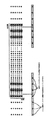
図7に、DVB−T規格やISDB−T規格で採用されているSP信号のOFDMシンボル内における配置パターンを示す。
【0011】
DVB−T規格やISDB−T規格では、サブキャリア方向(周波数方向)に12本のサブキャリアに1本の割合でBPSK変調されたSP信号が挿入されている。さらに、DVB−T規格やISDB−T規格では、SP信号の挿入位置をOFDMシンボル毎に3サブキャリアずつ周波数方向にシフトさせている。その結果、OFDMシンボル方向(時間方向)の同一のサブキャリアに対して、4OFDMシンボルに1回の割合でSP信号が挿入されることとなる。
【0012】
このようにDVB−T規格やISDB−T規格では、SP信号を空間的に散在させた状態でOFDMシンボルに挿入し、本来の情報に対するSP信号の冗長度を低くしている。
【0013】
ところで、このSP信号を用いて伝送路の特性を算出する場合、SP信号が挿入されたサブキャリアに対してはその特性を特定することはできるが、それ以外のサブキャリア即ち本来の情報が含まれているその他のサブキャリアに対しては、その特性を直接的に算出することはできない。そのため、受信側では、2次元補間フィルタを用いてSP信号をフィルタリングすることにより、本来の情報が含まれている他のサブキャリアの伝送路の特性を推定している。
【0014】
通常、2次元補間フィルタを用いた伝送路特性の推定処理は以下のように行われる。
【0015】
伝送路特性の推定処理を行う場合、まず、受信したOFDM信号から、情報成分を取り除き、図7に示した位置に挿入されたSP信号のみを抽出する。
【0016】
続いて、図8に示すように、抽出したSP信号を時間方向の補間フィルタに入力して時間方向補間処理を行い、OFDMシンボル毎に、SP信号が配置されているサブキャリアの伝送路特性を推定する。その結果、図9に示すように、全てのOFDMシンボルに対して、周波数方向に3サブキャリア毎、伝送路特性を推定することができる。
【0017】
続いて、図10に示すように、時間方向に補間したSP信号を周波数方向の補間フィルタに入力して周波数方向補間処理を行い、OFDMシンボル内の全サブキャリアの伝送路特性を推定する。その結果、受信したOFDM信号の全てのサブキャリアに対して、伝送路特性を推定することができる。
【0018】
ここで、補間処理を行う場合、一般的にフィルタの減衰特性や遷移特性を向上させるため、フィルタのタップを多くすることが望ましい。しかしながら、OFDM信号の伝送路特性の推定を行う場合、時間方向の補間処理にタップ数が多いフィルタを用いると、遅延線の遅延量が非常に大きくなってしまい実装が困難となってしまう。このような実装上の理由から、伝送路特性の推定を行う場合には、時間方向フィルタに、ハードウェア規模の小さい0次ホールドフィルタが用いられるのが一般的である。
【0019】
一方、OFDM信号の周波数方向の補間処理を行う場合は、時間方向と比較して遅延線の遅延量が小さい。そのため、時間方向フィルタよりもタップ数が多いフィルタを用いて、減衰特性や遷移特性を向上させることができる。
【0020】
21タップのFIRフィルタによって周波数方向フィルタを実現した場合の構成例を図11に示す。図11に示すFIRフィルタ200は、第1から第20の20個の遅延素子201〜220と、0番目から20番目の21個の乗算器230〜250と、加算器251とから構成される。
【0021】
このFIRフィルタ200には、入力信号として、3サブキャリア間隔で伝送路特性が推定された信号が、時間方向フィルタから周波数方向(サブキャリア方向)に順次入力される。なお、伝送路の特性が推定されていない部分(本来の情報が含まれている部分)では、0が入力される。
【0022】
第1の遅延素子201は、入力信号を1タイミング分遅延させる。第2の遅延素子202は、第1の遅延素子201の出力信号をさらに1タイミング分遅延させる。第3の遅延素子203は、第2の遅延素子202の出力信号をさらに1タイミング分遅延させる。以後、各遅延素子は、直前の遅延素子の出力信号を1タイミング分遅延させる。すなわち、各遅延素子201〜220からは、1〜20タイミング分遅延された遅延信号が出力される。また、0番目の乗算器230は遅延されていない入力信号に係数k0を乗算し、1番目の乗算器231は第1の遅延素子201の出力信号に係数k1を乗算し、2番目の乗算器232は第2の遅延素子202の出力信号に係数k2を乗算し、以後、各乗算器232〜250は対応する遅延素子203〜220の出力信号に係数k3〜k20を乗算する。そして、加算器251は、全ての乗算器230〜250の乗算出力を加算して出力する。
【0023】
そして、各係数k0〜k20は、遅延素子の中心位置にあるサブキャリアの伝送路特性を3倍補間するように、予め設定されている。
【0024】
この結果、このFIRフィルタ200では、OFDMシンボル内の各サブキャリアに対する伝送路特性を推定することができる。
【0025】
以上のように時間方向補間フィルタと周波数方向補間フィルタを用いて2次元的な補間処理を施すことにより、全てのサブキャリアにおける伝送路特性を受信側で推定することができる。
【0026】
【非特許文献1】
「地上デジタル音声放送用受信装置 標準規格(望ましい仕様) ARIB STD−B30 1.1版」,社団法人電波産業界,平成13年5月31日 策定,平成14年3月28日 1.1改定,p.10−14
【0027】
【発明が解決しようとする課題】
ところで、周波数方向の補間を行う場合、OFDMシンボル単位で、フィルタリング処理を完結させなければならない。すなわち、連続したシーケンシャルなデータではなく、ある一定のデータ単位毎に、フィルタリング処理を行わなければならない。
【0028】
そのため、周波数方向の補間処理で、OFDMシンボル内の端部分(低周波部分或いは高周波部分)のサブキャリアを補間点とするときには、図12に示すように、OFDMシンボルの帯域外の信号成分が補間用のサンプル信号としてフィルタ内に含まれてしまい、実際に受信した信号が入力されていなければならない位置の遅延素子内に真値を供給することができなかった。
【0029】
一般的に、補間処理を行う場合、所定の位置の遅延素子内に真値を供給できない場合には、そこに適当な値を仮定して補間点を求める。
【0030】
しかしながら、適当な値を仮定することに伴って補間の誤差が増大してしまう。
【0031】
従って、伝送路特性の推定値に誤差を生ずることになる。すなわち、図13に示すように、OFDMシンボルの帯域端のサブキャリア(低周波数部分及び高周波数部分のサブキャリア)の伝送路特性の推定値は、OFDMシンボルの帯域中心部分のサブキャリアの伝送路特性の推定値と比較して誤差が大きくなってしまう。
【0032】
本発明は、このような従来の実情に鑑みて提案されたものであり、高精度に伝送路の伝達特性を推定して、正確な等化処理を行うことができるOFDM復調装置及び方法を提供することを目的とする。
【0033】
【課題を解決するための手段】
本発明に係るOFDM復調装置は、所定の帯域内の複数のサブキャリアに対して情報が分割されて直交変調されることにより生成された伝送シンボルを伝送単位とし、特定の電力であって且つ特定の位相とされたパイロット信号が上記伝送シンボル内の所定のサブキャリアに離散的に挿入された直交周波数分割多重(OFDM)信号を復調するOFDM復調装置であって、上記OFDM信号を上記伝送シンボル単位で離散フーリエ変換する離散フーリエ変換手段と、上記離散フーリエ変換手段により離散フーリエ変換された信号から伝送シンボル毎に上記パイロット信号を抽出するパイロット信号抽出手段と、上記パイロット信号抽出手段により抽出された上記パイロット信号を時間方向補間フィルタ及び周波数方向補間フィルタを用いて補間することにより伝送シンボル内の全てのサブキャリアの伝送路特性を算出し、算出された各サブキャリアの伝送路特性に基づき上記離散フーリエ変換手段により離散フーリエ変換された信号を波形等化する波形等化手段とを備え、上記波形等化手段は、時間方向補間フィルタにより補間されたのちの伝送路特性に対して、低周波数側の帯域外部分の伝送路特性を高周波数側の末端部分の伝送路特性から巡回的にコピーし、高周波数側の帯域外部分の伝送路特性を低周波数側の末端部分の伝送路特性から巡回的にコピーし、周波数範囲を拡大した伝送路特性を上記周波数方向補間フィルタに入力する。
【0034】
本発明に係るOFDM復調方法は、所定の帯域内の複数のサブキャリアに対して情報が分割されて直交変調されることにより生成された伝送シンボルを伝送単位とし、特定の電力であって且つ特定の位相とされたパイロット信号が上記伝送シンボル内の所定のサブキャリアに離散的に挿入された直交周波数分割多重(OFDM)信号を復調するOFDM復調方法であって、上記OFDM信号を上記伝送シンボル単位で離散フーリエ変換し、離散フーリエ変換された信号から伝送シンボル毎に上記パイロット信号を抽出し、抽出された上記パイロット信号を時間方向補間フィルタを用いて時間方向に補間して伝送路特性を推定し、時間方向補間フィルタにより補間されたのちの伝送路特性に対して、低周波数側の帯域外部分の伝送路特性を高周波数側の末端部分の伝送路特性から巡回的にコピーし、高周波数側の帯域外部分の伝送路特性を低周波数側の末端部分の伝送路特性から巡回的にコピーし、周波数範囲を拡大した伝送路特性を生成し、上記周波数範囲が拡大された伝送路特性を周波数方向補間フィルタを用いて補間することにより伝送シンボル内の全てのサブキャリアの伝送路特性を算出し、算出された各サブキャリアの伝送路特性に基づき離散フーリエ変換された信号を波形等化することを特徴とする。
【0035】
本発明に係るOFDM復調装置及び方法では、低周波数側の帯域外部分の伝送路特性を高周波数側の末端部分の伝送路特性から巡回的にコピーし、高周波数側の帯域外部分の伝送路特性を低周波数側の末端部分の伝送路特性から巡回的にコピーし、周波数範囲を拡大した伝送路特性を生成し、上記周波数範囲が拡大された伝送路特性を周波数方向補間フィルタを用いて補間することにより、伝送シンボル内の全てのサブキャリアの伝送路特性を算出する。
【0036】
【発明の実施の形態】
以下、本発明の実施の形態として、本発明を適用したOFDM受信装置について説明をする。
【0037】
図1に、本発明の実施の形態のOFDM受信装置1のブロック構成図を示す。この図1では、ブロック間で伝達される信号が複素信号の場合には太線で信号成分を表現し、ブロック間で伝達される信号が実数信号の場合には細線で信号成分を表現している。
【0038】
OFDM受信装置1は、図1に示すように、アンテナ2と、チューナ3と、A/D変換回路4と、デジタル直交復調回路5と、FFT演算回路6と、ウィンドウ同期回路7と、等化回路8と、デマッピング回路9と、誤り訂正回路10とを備えている。
【0039】
放送局から放送されたデジタルテレビジョン放送の放送波は、OFDM受信装置1のアンテナ2により受信され、RF信号としてチューナ3に供給される。
【0040】
アンテナ2により受信されたRF信号は、チューナ3によりIF信号に周波数変換され、A/D変換回路4に供給される。IF信号は、A/D変換回路4によりデジタル化され、デジタル直交復調回路5に供給される。なお、A/D変換回路4は、DVB−T規格(2Kモード)においては、このOFDM時間領域信号の有効シンボルを2048サンプル、ガードインターバルを例えば512サンプルでサンプリングされるようなクロックで量子化する。
【0041】
デジタル直交復調回路5は、所定の周波数(キャリア周波数)のキャリア信号を用いて、デジタル化されたIF信号を直交復調し、ベースバンドのOFDM信号を出力する。このデジタル直交復調回路5から出力されるベースバンドのOFDM信号は、FFT演算される前のいわゆる時間領域の信号である。このことから、以下デジタル直交復調後でFFT演算される前のベースバンド信号を、OFDM時間領域信号と呼ぶ。OFDM時間領域信号は、直交復調された結果、実軸成分(Iチャンネル信号)と、虚軸成分(Qチャネル信号)とを含んだ複素信号となる。デジタル直交復調回路5により出力されるOFDM時間領域信号は、FFT演算回路6及びウィンドウ同期回路7に供給される。
【0042】
FFT演算回路6は、OFDM時間領域信号に対してFFT演算を行い、各サブキャリアに直交変調されているデータを抽出して出力する。このFFT演算回路6から出力される信号は、FFTされた後のいわゆる周波数領域の信号である。このことから、以下、FFT演算後の信号をOFDM周波数領域信号と呼ぶ。
【0043】
FFT演算回路6は、1つのOFDMシンボルから有効シンボル長の範囲(例えば2048サンプル)の信号を抜き出し、すなわち、1つのOFDMシンボルからガードインターバル分の範囲を除き、抜き出した2048サンプルのOFDM時間領域信号に対してFFT演算を行う。具体的にその演算開始位置は、OFDMシンボルの境界から、ガードインターバルの終了位置までの間のいずれかの位置となる。この演算範囲のことをFFTウィンドウと呼ぶ。
【0044】
このようにFFT演算回路6から出力されたOFDM周波数領域信号は、OFDM時間領域信号と同様に、実軸成分(Iチャンネル信号)と、虚軸成分(Qチャネル信号)とからなる複素信号となっている。この複素信号は、例えば、16QAM方式や64QAM方式等で直交振幅変調された信号である。OFDM周波数領域信号は、等化回路8に供給される。
【0045】
ウィンドウ同期回路7は、入力されたOFDM時間領域信号を有効シンボル期間分遅延させて、ガードインターバル部分とこのガードインターバルの複写元となる信号との相関性を求め、この相関性が高い部分に基づきOFDMシンボルの境界位置を算出し、その境界位置を示すウィンドウ同期信号Wsyncを発生する。FFTウィンドウ同期回路7は、発生したウィンドウ同期信号WsyncをFFT演算回路6に供給する。
【0046】
等化回路8は、スキャッタードパイロット信号(SP信号)を用いて、OFDM周波数領域信号の位相等化及び振幅等化を行う。位相等化及び振幅等化がされたOFDM周波数領域信号は、デマッピング回路9に供給される。
【0047】
デマッピング回路9は、等化回路8により振幅等化及び位相等化されたOFDM周波数領域信号を、16QAM方式に従ってデマッピングを行ってデータの復号をする。デマッピング回路9により復号されたデータは、誤り訂正回路10に供給される。
【0048】
誤り訂正回路10は、供給されたデータに対して、例えば、ビタビ復号やリード−ソロモン符号を用いた誤り訂正を行う。誤り訂正が行われたデータは、例えば後段のMPEG復号回路等に供給される。
【0049】
つぎに、等化回路8についてさらに詳細に説明する。
【0050】
等化回路8は、SP信号抽出回路11と、時間方向補間フィルタ12と、周波数方向補間フィルタ13と、1/X回路14と、複素乗算回路15とを備えている。
【0051】
SP信号抽出回路11は、FFT演算回路6から出力されたOFDM周波数領域信号が供給される。SP信号抽出回路11は、OFDM周波数領域信号からSP信号のみを抽出する。SP信号は、各OFDMシンボル内に離散的に挿入されており、その挿入位置は予め規格により定められている。SP信号抽出回路11は、シンボル毎に異なるサブキャリア位置にSP信号が挿入されていることから、供給されたOFDM周波数領域信号のシンボル番号を参照し、そのシンボル番号からどのインデックス番号のサブキャリアにSP信号が挿入されているかを規格に基づき算出し、SP信号を抽出する。SP信号抽出回路11は、抽出したSP信号を時間方向補間フィルタ12に供給する。
【0052】
時間方向補間フィルタ12は、例えば0ホールドフィルタから構成され、SP信号を時間軸方向にフィルタリングすることによって補間処理を行い、伝送路特性を推定する。具体的には、この時間方向補間フィルタ12は、実際に抽出されたSP信号の値を3OFDMシンボル分ホールドすることによって補間処理を行う。時間方向補間処理がされたSP信号は、OFDMシンボル単位で、周波数方向補間フィルタ13に供給される。
【0053】
周波数方向補間フィルタ13は、FIR(Finite Impulse Response)フィルタから構成され、SP信号を周波数方向(サブキャリア方向)に補間し、OFDMシンボル内のすべてのサブキャリアに対する振幅及び位相の周波数特性を推定する。
【0054】
すなわち、伝送路の周波数特性H(ω)を推定する。この周波数方向補間フィルタ13により求められた全サブキャリアに対する伝送路の周波数特性H(ω)は、1/X回路14に供給される。
【0055】
1/X回路14は、推定された伝送路の周波数特性H(ω)に対して逆数演算を行う。逆数演算が行われた伝送路の周波数特性1/H(ω)は、複素乗算回路15に供給される。
【0056】
複素乗算回路15は、FFT演算回路6からOFDM周波数領域信号と、逆演算が行われた伝送路の周波数特性1/H(ω)とを複素乗算をし、波形等化を行う。
【0057】
つぎに、等化回路8内の周波数方向補間フィルタ13の構成についてさらに説明をする。
【0058】
周波数方向補間フィルタ13は、図2に示すように、メモリ21と、アドレス発生回路22と、3倍補間を行うFIRフィルタ23とを備えている。
【0059】
メモリ21には、時間方向フィルタ12で推定された3サブキャリア間隔の伝送路特性値が入力され、この伝送路特性値を伝送シンボル単位で記憶する。伝送シンボル単位で記憶された伝送路特性値は、アドレス発生回路22のアドレス制御に従い、1サブキャリア毎に順番に、メモリ21からFIRフィルタ23に入力される。
【0060】
ここで、アドレス発生回路22は、次のようにメモリ21に対するデータの拡張を行いながら、転送制御を行う。
【0061】
まず、伝送シンボルの低周波数側の帯域外に、図3に示すように、伝送シンボルの高周波数側の末端部分から巡回的に伝送路特性値をコピーし、低周波数側の帯域外まで周波数特性を拡大する。続いて、伝送シンボルの高周波数側の帯域外に、図4に示すように、伝送シンボルの低周波数側の末端部分から巡回的に伝送路特性値をコピーし、高周波数側の帯域外まで周波数特性を拡大する。そして、アドレス発生回路24は、周波数帯域を本来の伝送シンボルよりも拡大した周波数範囲で伝送路特性値を読み出し、低周波数側から順番に遅延素子に入力していく。
【0062】
離散フーリエ変換が行われた信号に対して、このように帯域外の信号を逆側の信号から巡回的にコピーすると、離散フーリエ変換の演算特性上、帯域の端部分での好適な補間を行うことができる。
【0063】
伝送シンボルの帯域外にコピーをする伝送路特性値の数は、FIRフィルタ23のタップ数に応じて定まる。例えば、21タップのFIRフィルタ23を用いるものとすれば、伝送シンボルの高周波数側及び低周波数側のそれぞれの末端部分の9つのサブキャリア内に含まれている3つの伝送路特性値とする。
【0064】
なお、アドレス発生回路22は、伝送路特性値がまだ推定されていない部分(本来の情報が含まれている部分)には0を入力する。
【0065】
FIRフィルタ23は、従来例において説明をした図11に示すFIRフィルタ200と同一のもので構成される。このFIRフィルタ23には、周波数帯域が拡張された伝送シンボルが、低周波数側から1サンプルずつ入力される。この結果、全サブキャリアに対する伝送路の特性値、すなわち、周波数特性H(ω)を出力することができる。
【0066】
以上のように伝送路特性値の周波数帯域を実際の伝送シンボルの周波数範囲よりも拡大することによって、図5に示すように、OFDMシンボル内の端部分(低周波部分或いは高周波部分)のサブキャリアを補間点とするときでも、フィルタに実際の受信信号を入力することができるので、正確な補間を行うことができる。
【0067】
以上のように本発明の実施の形態のOFDM受信装置1では、伝送シンボルの低周波数側及び高周波数側の帯域外に、それぞれ伝送シンボルの高周波数側及び低周波数側の末端部分から巡回的に伝送路特性値をコピーし、伝送路特性を帯域外まで拡大する。
【0068】
このことにより、本発明の実施の形態のOFDM受信装置1では、正確な等化処理を行うことができる。
【0069】
なお、OFDM受信装置1では、低周波数側の帯域外と高周波数側の帯域外の両者に対して巡回的に伝送路特性値をコピーしているが、低周波数側の帯域外と高周波数側の帯域外のいずれか一方のみに対して行っても良い。また、OFDM受信装置1では、時間方向補間フィルタ12を用いているが、このフィルタを設けなくてもよい。
【0070】
【発明の効果】
本発明に係るOFDM復調装置及び方法では、低周波数側の帯域外部分の伝送路特性を高周波数側の末端部分の伝送路特性から巡回的にコピーし、高周波数側の帯域外部分の伝送路特性を低周波数側の末端部分の伝送路特性から巡回的にコピーし、周波数範囲を拡大した伝送路特性を生成し、上記周波数範囲が拡大された伝送路特性を周波数方向補間フィルタを用いて補間することにより、伝送シンボル内の全てのサブキャリアの伝送路特性を算出する。
【0071】
このことにより、本発明に係るOFDM復調装置及び方法では、高精度に伝送路の伝達特性を推定して、正確な等化処理を行うことができる。
【図面の簡単な説明】
【図1】本発明の実施の形態のOFDM受信装置のブロック構成図である。
【図2】上記OFDM受信装置に備えられる周波数方向補間フィルタの構成を示す図である。
【図3】OFDMシンボルの低周波数側の帯域外の伝送路特性値を拡大する方法について説明をする図である。
【図4】OFDMシンボルの高周波数側の帯域外の伝送路特性値を拡大する方法について説明をする図である。
【図5】図3、図4に示すように伝送路特性値を拡大した場合における周波数方向フィルタによる補間を示す図である。
【図6】OFDM信号の伝送シンボルについて説明するための図である。
【図7】OFDM信号のスキャッタードパイロット信号の挿入位置について説明するための図である。
【図8】伝送路特性を推定する際の時間方向の補間フィルタ処理について説明するための図である。
【図9】時間方向補間フィルタにより伝送路特性を推定されたサブキャリアについて説明するための図である。
【図10】伝送路特性を推定する際の周波数方向の補間フィルタ処理について説明するための図である。
【図11】21タップのFIRフィルタの構成を説明するための図である。
【図12】OFDMシンボルの端部部分での周波数方向の補間処理について説明するための図である。
【図13】仮のデータを推定元として入力したため推定誤差が発生する領域について説明するための図である。
【符号の説明】
1 OFDM受信装置、2 アンテナ、3 チューナ、4 A/D変換回路、5 デジタル直交復調回路、6 FFT演算回路、7 ウィンドウ同期回路、8
等化回路、9 デマッピング回路、10 誤り訂正回路[0001]
TECHNICAL FIELD OF THE INVENTION
The present invention relates to an orthogonal frequency division multiplexing (OFDM) demodulation apparatus and method for demodulating an OFDM (Orthogonal Frequency Division Multiplexing) modulated signal.
[0002]
[Prior art]
As a method for transmitting digital signals, a modulation method called an orthogonal frequency division multiplexing (OFDM) is used. In the OFDM system, a number of orthogonal subcarriers (subcarriers) are provided in a transmission band, and data is allocated to the amplitude and phase of each subcarrier by PSK (Phase Shift Keying) or QAM (Quadrature Amplitude Modulation), and digital modulation is performed. It is a method to do.
[0003]
The OFDM system divides the transmission band by a number of subcarriers, so the band per subcarrier wave becomes narrower and the modulation speed becomes slower, but the total transmission speed is the same as that of the conventional modulation system. are doing. Further, in the OFDM system, since a number of subcarriers are transmitted in parallel, the symbol rate is reduced, the time length of the multipath relative to the time length of the symbol can be shortened, and multipath interference is reduced. It has the feature of.
[0004]
In the OFDM system, data is allocated to a plurality of subcarriers. Therefore, an IFFT (Inverse Fast Fourier Transform) arithmetic circuit that performs inverse Fourier transform during modulation, and an FFT (Fast Fourier Transform) that performs Fourier transform during demodulation. 3.) It has a feature that a transmission / reception circuit can be configured by using an arithmetic circuit.
[0005]
From the above characteristics, the OFDM system is often applied to terrestrial digital broadcasting that is strongly affected by multipath interference. As such terrestrial digital broadcasting employing the OFDM system, there are, for example, standards such as DVB-T (Digital Video Broadcasting-Terrestrial) and ISDB-T (Integrated Services Digital Broadcasting-Terrestrial).
[0006]
As shown in FIG. 6, a transmission symbol of the OFDM scheme (hereinafter, referred to as an OFDM symbol) is an effective symbol which is a signal period in which an IFFT is performed at the time of transmission, and a waveform of a part of the latter half of the effective symbol is copied as it is. And a guard interval. The guard interval is provided in the first half of the OFDM symbol. In the OFDM method, by providing such a guard interval, inter-symbol interference due to multipath is allowed, and multipath resistance is improved.
[0007]
For example, in
[0008]
In the OFDM system, it is specified that a plurality of OFDM symbols as described above are collected to form a transmission unit called one OFDM transmission frame. For example, in the ISDB-T SB standard, to form a 1OFDM transmission frame 204OFDM symbol. In the OFDM system, for example, a pilot signal insertion position is determined based on the OFDM transmission frame unit.
[0009]
Further, in the OFDM method using QAM-based modulation as a modulation method for each subcarrier, if distortion occurs in a signal modulated on each subcarrier due to the influence of multipath or the like during transmission, the amplitude and phase of each subcarrier are changed. The characteristics will be different. Therefore, on the receiving side, it is necessary to equalize the waveform of the received signal so that the amplitude and phase of each subcarrier become equal. In the OFDM system, a pilot signal having a predetermined amplitude and a predetermined phase is scattered in a transmission symbol on a transmission side on a transmission side, and the amplitude and phase of the pilot signal are monitored on a reception side, and the frequency of a transmission path is monitored. The characteristics are determined, and the received signal is equalized based on the determined characteristics of the transmission path. In the OFDM system, a pilot signal used to calculate the characteristics of a transmission path is called a scattered pilot signal (SP) signal.
[0010]
FIG. 7 shows an arrangement pattern of an SP signal in an OFDM symbol adopted in the DVB-T standard or the ISDB-T standard.
[0011]
According to the DVB-T standard or the ISDB-T standard, an SP signal that is BPSK-modulated is inserted at a rate of one per 12 subcarriers in the subcarrier direction (frequency direction). Further, in the DVB-T standard or the ISDB-T standard, the insertion position of the SP signal is shifted in the frequency direction by three subcarriers for each OFDM symbol. As a result, the SP signal is inserted once every four OFDM symbols for the same subcarrier in the OFDM symbol direction (time direction).
[0012]
As described above, according to the DVB-T standard and the ISDB-T standard, SP signals are inserted into OFDM symbols in a state of being scattered spatially, so that the redundancy of the SP signals with respect to the original information is reduced.
[0013]
By the way, when the characteristics of the transmission path are calculated using this SP signal, the characteristics can be specified for the subcarrier into which the SP signal is inserted, but the other subcarriers, that is, the original information is not included. The characteristics of other subcarriers cannot be calculated directly. Therefore, the receiving side estimates the characteristics of the transmission path of another subcarrier including the original information by filtering the SP signal using a two-dimensional interpolation filter.
[0014]
Normally, the processing of estimating transmission path characteristics using a two-dimensional interpolation filter is performed as follows.
[0015]
When performing transmission path characteristic estimation processing, first, information components are removed from the received OFDM signal, and only the SP signal inserted at the position shown in FIG. 7 is extracted.
[0016]
Subsequently, as shown in FIG. 8, the extracted SP signal is input to a time-direction interpolation filter to perform time-direction interpolation processing, and for each OFDM symbol, the transmission path characteristics of the subcarrier on which the SP signal is arranged are determined. presume. As a result, as shown in FIG. 9, the transmission path characteristics can be estimated for every three subcarriers in the frequency direction for all OFDM symbols.
[0017]
Subsequently, as shown in FIG. 10, the SP signal interpolated in the time direction is input to an interpolation filter in the frequency direction to perform frequency direction interpolation processing, thereby estimating the transmission path characteristics of all subcarriers in the OFDM symbol. As a result, transmission path characteristics can be estimated for all subcarriers of the received OFDM signal.
[0018]
Here, when performing the interpolation processing, it is generally desirable to increase the number of filter taps in order to improve the attenuation characteristics and transition characteristics of the filter. However, when estimating the transmission path characteristics of an OFDM signal, if a filter having a large number of taps is used in the interpolation process in the time direction, the delay amount of the delay line becomes extremely large, and mounting becomes difficult. For such reasons of mounting, when estimating transmission path characteristics, it is common to use a zero-order hold filter with a small hardware scale as the time direction filter.
[0019]
On the other hand, when performing interpolation processing in the frequency direction of the OFDM signal, the delay amount of the delay line is smaller than in the time direction. Therefore, a filter having a larger number of taps than the time direction filter can be used to improve the attenuation characteristics and the transition characteristics.
[0020]
FIG. 11 shows a configuration example when a frequency direction filter is realized by a 21-tap FIR filter. The
[0021]
To the
[0022]
The
[0023]
The coefficients k0 to k20 are set in advance so that the transmission path characteristics of the subcarrier at the center position of the delay element are tripled.
[0024]
As a result, the
[0025]
As described above, by performing two-dimensional interpolation processing using the time direction interpolation filter and the frequency direction interpolation filter, it is possible to estimate the transmission path characteristics of all subcarriers on the receiving side.
[0026]
[Non-patent document 1]
"Digital Terrestrial Audio Broadcasting Receiver Standard (ARIB STD-B30 Version 1.1)", Established on May 31, 2001, Revised on March 28, 2002, 1.1 , P. 10-14
[0027]
[Problems to be solved by the invention]
By the way, when performing interpolation in the frequency direction, the filtering process must be completed in OFDM symbol units. That is, it is necessary to perform the filtering process not for continuous sequential data but for each certain data unit.
[0028]
Therefore, when the sub-carrier at the end portion (low-frequency portion or high-frequency portion) in the OFDM symbol is used as the interpolation point in the interpolation process in the frequency direction, the signal component outside the band of the OFDM symbol is interpolated as shown in FIG. And a true value cannot be supplied to a delay element at a position where an actually received signal must be input.
[0029]
Generally, when an interpolation process is performed, if a true value cannot be supplied to a delay element at a predetermined position, an interpolation point is determined by assuming an appropriate value there.
[0030]
However, assuming an appropriate value increases the interpolation error.
[0031]
Therefore, an error occurs in the estimated value of the transmission path characteristic. That is, as shown in FIG. 13, the estimated value of the channel characteristics of the subcarriers at the band edge of the OFDM symbol (the subcarriers at the low frequency portion and the high frequency portion) is calculated based on the transmission channel of the subcarrier at the band center portion of the OFDM symbol. The error becomes larger than the estimated value of the characteristic.
[0032]
The present invention has been proposed in view of such a conventional situation, and provides an OFDM demodulator and a method capable of accurately estimating a transfer characteristic of a transmission path and performing an accurate equalization process. The purpose is to do.
[0033]
[Means for Solving the Problems]
The OFDM demodulator according to the present invention uses a transmission symbol generated by dividing and orthogonally modulating information on a plurality of subcarriers within a predetermined band as a transmission unit, and has a specific power and a specific An OFDM demodulator demodulates an orthogonal frequency division multiplexing (OFDM) signal in which a pilot signal having a phase of .pi. Is discretely inserted into a predetermined subcarrier in the transmission symbol. Discrete Fourier transform means for performing a discrete Fourier transform on, pilot signal extracting means for extracting the pilot signal for each transmission symbol from the signal subjected to the discrete Fourier transform by the discrete Fourier transform means, and the pilot signal extracting means Complement the pilot signal using the time direction interpolation filter and the frequency direction interpolation filter. By calculating the channel characteristics of all the subcarriers in the transmission symbol, a waveform for equalizing the waveform of the signal subjected to the discrete Fourier transform by the discrete Fourier transform means based on the calculated channel characteristics of each subcarrier, etc. The waveform equalization means transmits the transmission path characteristic of the low frequency side outside the band to the transmission path characteristic after interpolation by the time direction interpolation filter at the end portion of the high frequency side. The transmission path characteristics are copied cyclically from the transmission path characteristics, and the transmission path characteristics for the outside of the band on the high frequency side are cyclically copied from the transmission path characteristics at the end portion on the low frequency side. Input to the interpolation filter.
[0034]
In the OFDM demodulation method according to the present invention, a transmission symbol generated by dividing and orthogonally modulating information on a plurality of subcarriers within a predetermined band is used as a transmission unit, and has a specific power and a specific An OFDM demodulation method for demodulating an orthogonal frequency division multiplexing (OFDM) signal in which a pilot signal having a phase of (i) is discretely inserted into predetermined subcarriers in the transmission symbol, wherein the OFDM signal is divided into transmission symbol units Discrete Fourier transform, extract the pilot signal for each transmission symbol from the discrete Fourier transformed signal, and estimate the transmission path characteristics by interpolating the extracted pilot signal in the time direction using a time direction interpolation filter In contrast to the transmission path characteristics interpolated by the time-direction interpolation filter, The frequency range is expanded by cyclically copying from the transmission path characteristics at the terminal part on the number side and the transmission path characteristics outside the band on the high frequency side from the transmission path characteristic at the terminal part on the low frequency side. The transmission path characteristics are generated, and the transmission path characteristics of all the subcarriers in the transmission symbol are calculated by interpolating the transmission path characteristics with the expanded frequency range using a frequency direction interpolation filter. It is characterized in that the signal subjected to discrete Fourier transform is equalized in waveform based on the transmission path characteristics of the carrier.
[0035]
In the OFDM demodulation apparatus and method according to the present invention, the transmission path characteristics for the outside of the band on the low frequency side are cyclically copied from the transmission path characteristics at the end portion on the high frequency side, and the transmission path for the outside of the band on the high frequency side is copied. The characteristics are cyclically copied from the transmission path characteristics at the end portion on the low frequency side, a transmission path characteristic with an expanded frequency range is generated, and the transmission path characteristics with the expanded frequency range are interpolated using a frequency direction interpolation filter. By doing so, the transmission path characteristics of all subcarriers in the transmission symbol are calculated.
[0036]
BEST MODE FOR CARRYING OUT THE INVENTION
Hereinafter, an OFDM receiving apparatus to which the present invention is applied will be described as an embodiment of the present invention.
[0037]
FIG. 1 shows a block diagram of an OFDM receiver 1 according to an embodiment of the present invention. In FIG. 1, when the signal transmitted between the blocks is a complex signal, the signal component is represented by a thick line, and when the signal transmitted between the blocks is a real number signal, the signal component is represented by a thin line. .
[0038]
As shown in FIG. 1, the OFDM receiver 1 includes an antenna 2, a
[0039]
A broadcast wave of a digital television broadcast broadcast from a broadcast station is received by the antenna 2 of the OFDM receiver 1 and supplied to the
[0040]
The RF signal received by the antenna 2 is frequency-converted into an IF signal by the
[0041]
The digital
[0042]
The
[0043]
The
[0044]
The OFDM frequency domain signal output from the
[0045]
The
[0046]
The equalization circuit 8 performs phase equalization and amplitude equalization of the OFDM frequency domain signal using the scattered pilot signal (SP signal). The OFDM frequency domain signal subjected to the phase equalization and the amplitude equalization is supplied to the
[0047]
The
[0048]
The
[0049]
Next, the equalizing circuit 8 will be described in more detail.
[0050]
The equalization circuit 8 includes an SP
[0051]
The SP
[0052]
The time
[0053]
The frequency
[0054]
That is, the frequency characteristic H (ω) of the transmission path is estimated. The frequency characteristics H (ω) of the transmission path for all subcarriers obtained by the frequency
[0055]
The 1 /
[0056]
The
[0057]
Next, the configuration of the frequency
[0058]
As shown in FIG. 2, the frequency
[0059]
The transmission path characteristic values at three subcarrier intervals estimated by the
[0060]
Here, the
[0061]
First, as shown in FIG. 3, the transmission line characteristic values are cyclically copied from the end portion of the transmission symbol on the high frequency side to the outside of the band on the low frequency side of the transmission symbol, and the frequency characteristic is copied out of the band on the low frequency side. To enlarge. Subsequently, as shown in FIG. 4, the transmission path characteristic values are cyclically copied from the lower end of the transmission symbol to the outside of the high frequency side of the transmission symbol. Expand the characteristics. Then, the
[0062]
When the signal out of the band is cyclically copied from the signal on the opposite side to the signal on which the discrete Fourier transform has been performed, a suitable interpolation is performed at an end portion of the band due to the operation characteristics of the discrete Fourier transform. be able to.
[0063]
The number of transmission path characteristic values that are copied outside the transmission symbol band is determined according to the number of taps of the
[0064]
The
[0065]
The
[0066]
As described above, by expanding the frequency band of the transmission path characteristic value from the frequency range of the actual transmission symbol, as shown in FIG. 5, the subcarrier at the end portion (low-frequency portion or high-frequency portion) in the OFDM symbol Can be used as an interpolation point, an actual received signal can be input to the filter, so that accurate interpolation can be performed.
[0067]
As described above, in the OFDM receiving apparatus 1 according to the embodiment of the present invention, out of the low-frequency side and the high-frequency side of the transmission symbol, the transmission symbol is cyclically shifted from the high-frequency side and the low-frequency side end portion of the transmission symbol, respectively. The transmission path characteristic value is copied, and the transmission path characteristic is expanded out of the band.
[0068]
Thus, the OFDM receiver 1 according to the embodiment of the present invention can perform an accurate equalization process.
[0069]
In the OFDM receiver 1, the transmission line characteristic values are cyclically copied for both the out-of-band on the low frequency side and the out-of-band on the high frequency side. May be performed for only one of the out-of-bands. Further, the OFDM receiver 1 uses the time-
[0070]
【The invention's effect】
In the OFDM demodulation apparatus and method according to the present invention, the transmission path characteristics for the outside of the band on the low frequency side are cyclically copied from the transmission path characteristics at the end portion on the high frequency side, and the transmission path for the outside of the band on the high frequency side is copied. The characteristics are cyclically copied from the transmission path characteristics at the end portion on the low frequency side, a transmission path characteristic with an expanded frequency range is generated, and the transmission path characteristics with the expanded frequency range are interpolated using a frequency direction interpolation filter. By doing so, the transmission path characteristics of all subcarriers in the transmission symbol are calculated.
[0071]
Thus, the OFDM demodulation apparatus and method according to the present invention can accurately estimate the transfer characteristics of the transmission path and perform accurate equalization processing.
[Brief description of the drawings]
FIG. 1 is a block diagram of an OFDM receiver according to an embodiment of the present invention.
FIG. 2 is a diagram showing a configuration of a frequency direction interpolation filter provided in the OFDM receiver.
FIG. 3 is a diagram illustrating a method of expanding a transmission path characteristic value outside a band on a low frequency side of an OFDM symbol.
FIG. 4 is a diagram illustrating a method of expanding a transmission path characteristic value outside a band on the high frequency side of an OFDM symbol.
FIG. 5 is a diagram showing interpolation by a frequency direction filter when the transmission path characteristic value is expanded as shown in FIGS. 3 and 4;
FIG. 6 is a diagram illustrating a transmission symbol of an OFDM signal.
FIG. 7 is a diagram illustrating an insertion position of a scattered pilot signal of an OFDM signal.
FIG. 8 is a diagram for describing a time-direction interpolation filter process when estimating a transmission path characteristic;
FIG. 9 is a diagram for describing subcarriers whose transmission path characteristics have been estimated by a time-direction interpolation filter.
FIG. 10 is a diagram for describing interpolation filter processing in the frequency direction when estimating transmission path characteristics.
FIG. 11 is a diagram illustrating a configuration of a 21-tap FIR filter.
FIG. 12 is a diagram for describing interpolation processing in the frequency direction at an end portion of an OFDM symbol.
FIG. 13 is a diagram for describing an area where an estimation error occurs because temporary data is input as an estimation source.
[Explanation of symbols]
Reference Signs List 1 OFDM receiver, 2 antenna, 3 tuner, 4 A / D conversion circuit, 5 digital quadrature demodulation circuit, 6 FFT operation circuit, 7 window synchronization circuit, 8
Equalization circuit, 9 demapping circuit, 10 error correction circuit
Claims (6)
上記OFDM信号を上記伝送シンボル単位で離散フーリエ変換する離散フーリエ変換手段と、
上記離散フーリエ変換手段により離散フーリエ変換された信号から伝送シンボル毎に上記パイロット信号を抽出するパイロット信号抽出手段と、
上記パイロット信号抽出手段により抽出された上記パイロット信号を周波数方向補間フィルタを用いて補間することにより伝送シンボル内の全てのサブキャリアの伝送路特性を算出し、算出された各サブキャリアの伝送路特性に基づき上記離散フーリエ変換手段により離散フーリエ変換された信号を波形等化する波形等化手段とを備え、
上記波形等化手段は、
上記周波数方向補間フィルタの入力の際に、上記所定の帯域外の周波数の伝送路特性として、上記所定の帯域内の伝送路特性を巡回的に用いること
を特徴とするOFDM復調装置。A transmission symbol generated by dividing and orthogonally modulating information for a plurality of subcarriers within a predetermined band is used as a transmission unit, and a pilot signal having a specific power and a specific phase is transmitted as described above. In an OFDM demodulator for demodulating an orthogonal frequency division multiplexing (OFDM) signal discretely inserted into a predetermined subcarrier in a transmission symbol,
Discrete Fourier transform means for performing a discrete Fourier transform of the OFDM signal in units of the transmission symbol;
Pilot signal extracting means for extracting the pilot signal for each transmission symbol from the signal subjected to discrete Fourier transform by the discrete Fourier transform means,
The pilot signal extracted by the pilot signal extracting means is interpolated using a frequency direction interpolation filter to calculate the channel characteristics of all subcarriers in the transmission symbol, and the calculated channel characteristics of each subcarrier are calculated. Waveform equalizing means for equalizing the waveform of the signal subjected to discrete Fourier transform by the discrete Fourier transform means based on
The waveform equalizing means includes:
An OFDM demodulator characterized in that, at the time of inputting the frequency direction interpolation filter, a transmission path characteristic in the predetermined band is cyclically used as a transmission path characteristic of a frequency outside the predetermined band.
を特徴とする請求項1記載のOFDM復調装置。The waveform equalizing means cyclically copies the transmission path characteristics outside the band on the low frequency side from the pilot signal at the end portion on the high frequency side, and transmits the transmission path characteristics having an expanded frequency range to the frequency direction interpolation filter. 2. The OFDM demodulator according to claim 1, wherein the signal is input to the OFDM demodulator.
を特徴とする請求項1記載のOFDM復調装置。The waveform equalizing means cyclically copies the transmission path characteristics for the outside of the band on the high frequency side from the pilot signal at the end portion on the low frequency side, and transmits the transmission path characteristics with the expanded frequency range to the frequency direction interpolation filter. 2. The OFDM demodulator according to claim 1, wherein the signal is input to the OFDM demodulator.
上記OFDM信号を上記伝送シンボル単位で離散フーリエ変換し、
離散フーリエ変換された信号から伝送シンボル毎に上記パイロット信号を抽出し、
上記所定の帯域外の周波数の伝送路特性として、上記所定の帯域内の上記パイロット信号を巡回的に用いて周波数範囲を拡大し、
上記周波数範囲が拡大された伝送路特性を周波数方向補間フィルタを用いて補間することにより伝送シンボル内の全てのサブキャリアの伝送路特性を算出し、
算出された各サブキャリアの伝送路特性に基づき離散フーリエ変換された信号を波形等化すること
を特徴とするOFDM復調方法。A transmission symbol generated by dividing and orthogonally modulating information for a plurality of subcarriers within a predetermined band is used as a transmission unit, and a pilot signal having a specific power and a specific phase is transmitted as described above. In an OFDM demodulation method for demodulating an orthogonal frequency division multiplexing (OFDM) signal discretely inserted into a predetermined subcarrier in a transmission symbol,
Performing a discrete Fourier transform of the OFDM signal in units of the transmission symbol;
Extracting the pilot signal for each transmission symbol from the signal subjected to discrete Fourier transform,
As a transmission path characteristic of a frequency outside the predetermined band, a frequency range is expanded by cyclically using the pilot signal within the predetermined band,
The transmission path characteristics of all the subcarriers in the transmission symbol are calculated by interpolating the transmission path characteristics whose frequency range has been expanded using a frequency direction interpolation filter,
An OFDM demodulation method characterized by equalizing the waveform of a signal subjected to discrete Fourier transform based on the calculated channel characteristics of each subcarrier.
を特徴とする請求項4記載のOFDM復調方法。It is characterized in that the transmission line characteristics for the outside of the band on the low frequency side are cyclically copied from the pilot signal at the end portion on the high frequency side, and the transmission line characteristics with an expanded frequency range are input to the frequency direction interpolation filter. The OFDM demodulation method according to claim 4, wherein
を特徴とする請求項4記載のOFDM復調方法。It is characterized in that the transmission line characteristics of the high frequency side outside the band are cyclically copied from the pilot signal at the lower end of the low frequency side, and the transmission line characteristics with an expanded frequency range are input to the frequency direction interpolation filter. The OFDM demodulation method according to claim 4, wherein
Priority Applications (1)
| Application Number | Priority Date | Filing Date | Title |
|---|---|---|---|
| JP2003096132A JP2004304590A (en) | 2003-03-31 | 2003-03-31 | Ofdm demodulator and method therefor |
Applications Claiming Priority (1)
| Application Number | Priority Date | Filing Date | Title |
|---|---|---|---|
| JP2003096132A JP2004304590A (en) | 2003-03-31 | 2003-03-31 | Ofdm demodulator and method therefor |
Publications (1)
| Publication Number | Publication Date |
|---|---|
| JP2004304590A true JP2004304590A (en) | 2004-10-28 |
Family
ID=33408288
Family Applications (1)
| Application Number | Title | Priority Date | Filing Date |
|---|---|---|---|
| JP2003096132A Abandoned JP2004304590A (en) | 2003-03-31 | 2003-03-31 | Ofdm demodulator and method therefor |
Country Status (1)
| Country | Link |
|---|---|
| JP (1) | JP2004304590A (en) |
Cited By (2)
| Publication number | Priority date | Publication date | Assignee | Title |
|---|---|---|---|---|
| JP2008526141A (en) * | 2004-12-22 | 2008-07-17 | クゥアルコム・インコーポレイテッド | Constrained hopping in wireless communication systems |
| JP2010517338A (en) * | 2007-01-19 | 2010-05-20 | トムソン ライセンシング | Interpolation method, channel estimation method and apparatus in OFDM system |
-
2003
- 2003-03-31 JP JP2003096132A patent/JP2004304590A/en not_active Abandoned
Cited By (3)
| Publication number | Priority date | Publication date | Assignee | Title |
|---|---|---|---|---|
| JP2008526141A (en) * | 2004-12-22 | 2008-07-17 | クゥアルコム・インコーポレイテッド | Constrained hopping in wireless communication systems |
| US8571132B2 (en) | 2004-12-22 | 2013-10-29 | Qualcomm Incorporated | Constrained hopping in wireless communication systems |
| JP2010517338A (en) * | 2007-01-19 | 2010-05-20 | トムソン ライセンシング | Interpolation method, channel estimation method and apparatus in OFDM system |
Similar Documents
| Publication | Publication Date | Title |
|---|---|---|
| CN101079866B (en) | OFDM demodulator, receiver and method | |
| JP4297093B2 (en) | Doppler frequency calculation apparatus and method, and OFDM demodulation apparatus | |
| JP5296776B2 (en) | Receiving device, receiving method, integrated circuit, digital television receiver, program | |
| KR101603342B1 (en) | Receiving apparatus, receiving method, and recording medium | |
| JP4816353B2 (en) | OFDM receiving apparatus and OFDM signal receiving method | |
| JP2008501272A (en) | Channel estimation in OFDM systems with high Doppler shift | |
| JP2005312027A (en) | Receiver | |
| EP2131512B1 (en) | OFDM reception device, OFDM reception method, OFDM reception circuit, integrated circuit and program | |
| JP2003101503A (en) | Ofdm equalizer and equalization method for ofdm | |
| JP2007134783A (en) | Apparatus and method for receiving orthogonal frequency division multiplex signal | |
| US8175204B2 (en) | Receiving device, signal processing method, and program | |
| JP2005286636A (en) | Digital broadcast receiver | |
| US20060146690A1 (en) | Methods, circuits and computer program products for estimating frequency domain channel in a DVB-T receiver using transform domain complex filtering | |
| JP4362954B2 (en) | Demodulator and demodulation method | |
| US7986615B2 (en) | Demodulating circuit, demodulating method, program, and receiving device | |
| JPH11298434A (en) | Ofdm demodulator | |
| WO2007096663A2 (en) | Ofdem channel estimation systems | |
| JP2009111749A (en) | Reception apparatus, reception method, and program | |
| WO2017013402A1 (en) | Receiver and method of receiving | |
| JP2002344411A (en) | Ofdm modulation apparatus and method | |
| JP2004304590A (en) | Ofdm demodulator and method therefor | |
| JP2002026861A (en) | Demodulator and demodulation method | |
| JP2002344410A (en) | Ofdm modulator | |
| JP2002344414A (en) | Ofdm demodulation apparatus and method | |
| JP4362955B2 (en) | Demodulator and demodulation method |
Legal Events
| Date | Code | Title | Description |
|---|---|---|---|
| A621 | Written request for application examination |
Free format text: JAPANESE INTERMEDIATE CODE: A621 Effective date: 20060118 |
|
| A762 | Written abandonment of application |
Free format text: JAPANESE INTERMEDIATE CODE: A762 Effective date: 20080226 |
|
| A977 | Report on retrieval |
Free format text: JAPANESE INTERMEDIATE CODE: A971007 Effective date: 20080303 |