【0001】
【発明の属する技術分野】
本発明は、投射光用の光源を備えるプロジェクタに関し、特に、プロジェクタの冷却方法に関するものである。
【0002】
【従来の技術】
従来より、電子機器における表示装置のひとつとして、映像源の画像を光学系を介してスクリーンに拡大投射する投射型表示装置としてのプロジェクタが知られている。
【0003】
プロジェクタは、光源、電源ユニットなどの発熱しやすい機器を有していることから、これらの発熱体の熱が光路上の光学部材に伝わると、光学部材の取り付け精度や熱特性に影響を与え、光学特性の低下を招くおそれがある。
【0004】
プロジェクタの熱対策に関する技術としては、例えば、ヒートシンクなどの放熱体を高温となる光学部材に取り付けて放熱させる技術がある(例えば、特許文献1参照)。
【0005】
【特許文献1】
特開平14−098937号公報
【0006】
【発明が解決しようとする課題】
【0007】
ところで、プロジェクタでは、光源の温度に応じて光源の光学特性が大きく変化する場合がある。光源の光学特性の変化は、投射画像の品質の不安定を招くことから、光源の温度変化はなるべく小さいのが好ましい。
【0008】
ところが、光源に対して放熱体を単に取り付けただけでは、光源の温度変化を十分に抑制できないおそれがある。特に、近年、プロジェクタの小型化や高精細化が進み、光源の温度管理がより重要になっている。
【0009】
また、光源の温度に応じて光源の光学特性が大きく変化する場合、電源投入後から光源の温度が安定するまでの間は投射画像が安定しないために使用を待機する必要がある。そのため、上記待機時間(ウォームアップ時間)の短縮化が望まれている。
【0010】
本発明は、上述する事情に鑑みてなされたものであり、投射画像の品質安定性の向上を図るとともに、電源投入後から投射画像の品質が安定するまでの待機時間を短縮することができるプロジェクタの冷却方法並びにプロジェクタを提供する。
【0011】
【課題を解決するための手段】
上記の目的を達成するために、本発明のプロジェクタの冷却方法は、投射光用の光源を備えるプロジェクタを冷却する方法であって、前記光源の温度に応じて前記光源からの放熱量を変化させることを特徴とする。
【0012】
本発明のプロジェクタの冷却方法では、光源の温度に応じて光源からの放熱量を変化させることにより、光源の温度変化を抑制することが可能となる。
すなわち、光源の温度が高い場合には光源からの放熱量を多くし、光源の温度が低い場合には光源からの放熱量を少なくすることにより、光源の温度変化が抑制される。
したがって、本発明のプロジェクタの冷却方法では、光源の温度変化に伴う輝度などの光学特性の変化が抑制され、投射画像の品質安定性の向上が図られる。
【0013】
また、上記の冷却方法によれば、電源投入後から投射画像の品質が安定するまでの待機時間(ウォームアップ時間)を短縮することが可能である。
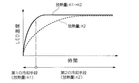
例えば、前記光源の電源投入後に、第1の放熱量で前記光源を放熱させる第1工程と、前記光源の温度上昇後に、前記第1の放熱量よりも多い第2の放熱量で前記光源を放熱させる第2工程とを有することにより、光源からの放射量が一定である場合に比べて、上記待機時間が短縮される。
【0014】
この場合、前記光源の発熱量をKm、前記第1の放熱量をK1、前記第2の放熱量をK2とするとき、 K1<Km≒K2 であるのが好ましい。
これによると、光源の電源投入直後には放熱量(K1)が少なく、光源が速やかに温度上昇するとともに、温度上昇後には光源の発熱量(Km)と放熱量(K2)とが釣り合い、光源の温度が安定する。なお、Km<K2であると、光源温度が低下し、光源特性が変化するので好ましくない。
【0015】
また、上記の冷却方法において、前記放熱量を変化させるタイミングは、熱移動に伴う時間的な遅れを考慮したものであるのが好ましい。
これにより、過度な温度上昇や温度降下が抑制され、光源の温度がさらに安定する。
【0016】
本発明のプロジェクタは、投射光用の光源を備えるプロジェクタにおいて、前記光源の温度に応じて前記光源からの放熱量を変化させる冷却装置を備えることを特徴とする。
【0017】
本発明のプロジェクタでは、冷却装置によって光源からの放熱量を変化させることにより、光源の温度変化を抑制することが可能となる。
そのため、光源の温度変化に伴う光源の光学特性の変化が抑制され、投射画像の品質安定性の向上が図られる。
【0018】
例えば、前記冷却装置は、放熱体と、前記放熱体と前記光源との接続状態を切り換える切換手段とを有するとよい。
この構成によれば、例えば、放熱体と光源とが接続することで光源からの放熱量が多くなり、放熱体と光源とが非接続となることで光源からの放熱量が少なくなる。したがって、光源の温度が高い場合には放熱体と光源とを接続し、光源の温度が低い場合には放熱体と光源とを非接続とすることにより、光源の温度変化が抑制される。
【0019】
この場合において、前記切換手段は、前記光源に熱的に接続され、温度に応じてばね定数が変化する形状記憶合金バネを含んでもよい。
この構成によれば、光源に熱的に接続された形状記憶合金バネは、光源の温度に応じてばね定数が変化する。そのため、そのばね定数の変化を利用して放熱体と光源との接続状態を切り換えることが可能となる。この場合、構成の簡素化が図られる。
【0020】
また、上記のプロジェクタにおいて、前記冷却装置は、冷却ファンと、前記冷却ファンの作動状態を制御する制御手段とを有する構成としてもよい。
この構成によれば、例えば、冷却ファンを作動させることで光源からの放熱量が多くなり、冷却ファンを停止させることで光源からの放熱量が少なくなる。したがって、光源の温度が高い場合には冷却ファンを作動し、光源の温度が低い場合には冷却ファンを停止させることにより、光源の温度変化が抑制される。
【0021】
また、上記のプロジェクタにおいて、前記光源は、発光ダイオード(Light Emitting Diode:LED)を含むLED光源であってもよい。
この構成によれば、光源がLED光源であることにより、小型化を図りやすい。
【0022】
【発明の実施の形態】
以下、本発明について図面を参照して説明する。
図1は、本発明のプロジェクタ及びその冷却方法を概念的に示す図である。
図1において、プロジェクタ1は、投射光用の光源2と、光源2を冷却するための冷却装置3とを備えている。
冷却装置3は、第1の放熱量(K1)で光源2を放熱させる第1の冷却手段4と、第1の放熱量(K1)よりも多い第2の放熱量(K2)で光源2を放熱させる第2の冷却手段5と、光源2の冷却手段として、第1の冷却手段4及び第2の冷却手段5のいずれかを選択する切換手段6とを有している。
【0023】
光源2としては、例えば、発光素子としてのLED(発光ダイオード、有機電界発光素子)を含むLED光源(LEDランプ)の他に、メタルハライドランプ、高圧水銀ランプ、ハロゲンランプ等が挙げられる。
【0024】
冷却手段4,5としては、例えば、放熱体としてのヒートシンク、冷却ファンなどを用いた空冷式の様々な冷却装置の他に、液状の冷媒を循環する装置などの液冷式の様々な冷却装置が挙げられる。なお、第1の冷却手段4は、光源2に対して強制的な冷却手段を設けないもの(例えば、自然放熱のみの場合)を含むものとする。
また、切換手段6としては、例えば、熱的な接続状態を切り換えるスイッチ類、冷却装置の作動状態を制御する制御装置、流体(冷媒)の流れを制御するバルブなどが挙げられる。
【0025】
ここで、図2はLEDの発光強度の温度依存性(温度−光強度比率)を示す図であり、図3はLEDの発光強度分布の温度依存性(光の波長−光強度分布)を示す図である。
図2及び図3に示すように、LEDの光強度は、温度上昇に伴い減少する。また、LEDにおける発光強度分布のピーク波長は、温度上昇に伴い長波長側にシフトする。そのため、LED光源を用いたプロジェクタでは、光源の温度が変化すると、光強度(輝度)が変化したり、光の波長が変化したりするため、投射映像の品質が不安定になる。
【0026】
図1に戻り、本発明のプロジェクタ1では、上述した温度変化に伴う光源2の光学特性の変化を抑制するために、冷却装置3によって光源2からの放熱量を変化させるようになっている。例えば、光源2の温度が低い場合には、第1の冷却手段4を用いて光源2を冷却して光源2からの放熱量を少なくし、光源2の温度が高い場合には、第2の冷却手段5を用いて光源2を冷却して光源2からの放熱量を多くする。
【0027】
光源2からの放熱量が少ない場合、自身の発熱に伴って光源2が温度上昇しやすくなるか、あるいは温度降下しにくくなる。また、光源2からの放熱量が多い場合、自身の発熱に伴って光源2が温度上昇しにくくなるか、あるいは温度降下しやすくなる。
【0028】
このように、プロジェクタ1では、冷却装置3によって光源2からの放熱量を変化させることにより、光源2の温度変化を抑制する。これにより、温度変化に伴う光源2の光学特性の変化が抑制され、投射画像の品質安定性の向上が図られる。
【0029】
このとき、光源2の温度は、計測してもしなくてもよい。光源2の温度を計測する場合、その計測結果に基づいて、第1の冷却手段4と第2の冷却手段5との切り換えを行うとよい。また、光源2の温度を計測しない場合は、例えば、温度に応じて物理特性が変化する物体(例えば、形状記憶合金バネなど)を用いて上記切り換えを行うとよい。なお、光源2の温度計測に代えて、光源2の近傍に配される部材や気体の温度など、光源2の温度に略比例して温度変化する部位の温度計測を行ってよい。また、予め光源2の温度変化の様子がわかっている場合には、時間の経過に応じて上記切り換えを行ってもよい。
【0030】
図4は、LED光源(LEDランプ)における、電源投入後のLED(PNジャンクション部)の温度変化の様子を示している。
図4に示すように、このLED光源では、電源投入後から約30分経過後に飽和温度に達している。すなわち、このLED光源では、電源投入後から約30分間は、温度変化が大きいために、光学特性が不安定になる。このように、電源投入後における光源の温度変化に伴って光源の光学特性が不安定になる場合には、プロジェクタの使用を待機することが好ましい(待機時間(ウォームアップ時間))。
【0031】
図1に戻り、このプロジェクタ1では、冷却装置3によって光源2からの放熱量を変化させることから、電源投入後から投射画像の品質が安定するまでの待機時間が短縮される。
【0032】
例えば、光源2の電源投入直後は、第1の冷却手段4(放熱量K1)を用いて光源2を冷却し、光源2の温度上昇後に、第2の冷却手段5(放熱量K2)を用いて光源2を冷却する。光源2の電源投入直後に、放熱量の低い第1の冷却手段4を用いることにより、自身の発熱によって光源2が速やかに温度上昇する。
【0033】
図5は、放熱量の切り換えを行う場合の電源投入直後からの光源2の温度変化の様子(実線)を示す図である。なお、図5の点線は、光源からの放熱量が一定の場合(第2の冷却手段5(放熱量K2)のみを使用した場合)を示している。
【0034】
図5の実線に示すように、光源2の電源投入後に、第1の冷却手段4(放熱量K1)で光源2を放熱させ、光源2の温度上昇後に、第2の冷却手段5(放熱量K2)で光源2を放熱させることにより、図5の点線で示す光源からの放射量が一定の場合に比べて、光源2が速やかに温度上昇し、上記飽和温度と同じ温度に達するまでの時間(待機時間)が短縮される。
【0035】
ここで、光源2の発熱量をKm、第1の冷却手段4の放熱量をK1、第2の冷却手段5の放熱量をK2、とするとき、 K1<Km≒K2 であるのが好ましい。この場合、前述したように、光源2の電源投入直後には、放熱量(K1)が少なくなり、光源2が速やかに温度上昇して待機時間の短縮化が図れる。一方、温度上昇して光源2が上記飽和温度に達した後には、光源2の発熱量(Km)と放熱量(K2)とが釣り合って、光源2の温度が安定する。
【0036】
上記放熱量の切り換えは、通常は、光源2が所定の温度(例えば、ランプ許容温度)に達した時点で行われる。ただし、光源2の温度変化の様子に熱移動に伴う時間的な遅れ(応答遅れ)が含まれる場合、その遅れを考慮して上記切り換えを行うのが好ましい。
【0037】
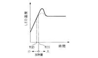
図6及び図7は、応答遅れを含む光源の温度変化の様子の例を示す図である。
例えば、図6に実線で示す例では、所定温度の時点T(1)で放熱量の切り換え(小→大)を行うとき、応答遅れによって過度な温度上昇(オーバーシュート)が生じている。これに対し、図6に点線で示すように、光源の温度上昇過程において、上記所定温度T(1)に達する少し前の時点T(2)で上記切り換えを行うことにより、過度な温度変化が抑制される。
【0038】
また、図7に実線で示す例では、光源の温度を安定させる過程で、所定温度の時点T(3)で放熱量の切り換え(大→小)を行うとき、応答遅れによって過度な温度降下(アンダーシュート)が生じている。これに対し、図7に点線で示すように、光源の温度降下過程において、所定温度T(3)に達する少し前の時点T(4)で上記切り換えを行うことにより、過度な温度変化が抑制される。
【0039】
次に、本発明のプロジェクタの具体的な実施の形態例について図面を参照して説明する。
ここでは、一実施の形態例として、空間光変調装置、すなわち光変調手段(ライトバルブ)として、R(赤)、G(緑)、B(青)の3色に対応した3枚の液晶装置(液晶パネル)を備えた3板式液晶プロジェクタについて説明する。なお、本発明は、1板式液晶プロジェクタや、ライトバルブとして他の空間光変調装置(例えば DMD;Digital Mirror Device など)を用いたプロジェクタにも適用可能である。
【0040】
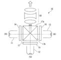
図8は液晶プロジェクタ10の概略的な全体構成を模式的に示す図である。
図8において、プロジェクタ10は、光源11,12,13、光源11,12,13からの各光を変調する液晶ライトバルブ14,15,16、変調された各光を合成するクロスダイクロイックプリズム17、及びプリズム17から出射された光を不図示のスクリーンに拡大投射する投射系18等を含んで構成される。ここで、光源11はR(赤)、12はG(緑)、13はB(青)、の光をそれぞれ発するものであり、ライトバルブ14はR、15はG、16はB、の光にそれぞれ対応している。
【0041】
光源11,12,13として、本例では、発光素子としてのLED(発光ダイオード、有機電界発光素子)を含むLED光源(LEDランプ)が用いられている。
【0042】
ライトバルブ14,15,16は、例えば、スイッチング素子としての薄膜トランジスタ(TFT;Thin Film Transistor)と透過型の液晶セルとを含み、外部からの画像情報(あるいは映像情報)に基づいて光源11,12,13からの光を変調する。
【0043】
プリズム17は、4つの直角プリズムが貼り合わされた構造からなり、全体が略立方体状に形成されている。また、プリズム17は、赤色光(R)を反射する誘電体多層膜17aと青色光(B)を反射する誘電体多層膜17bとを含み、ライトバルブ15からの緑色光(G)を透過しかつライトバルブ14からの赤色光(R)とライトバルブ16からの青色光(B)とを折り曲げてこれらの3色の光を合成し、カラー画像を形成する。
【0044】
投射系18は、拡大投射光学系を含み、プリズム17から出射された光を不図示のスクリーン上に投射する。この投射により、スクリーン上には、拡大されたカラー画像が表示される。
【0045】
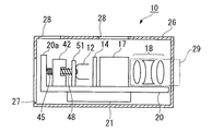
図9及び図10は、上記プロジェクタ10における各構成部材の配置の様子を模式的に示す図であり、図9は平面図、図10は側面図である。
図9及び図10において、ライトバルブ14,15,16、プリズム17、及び投射系18の各光学部材はそれぞれ、ベースプレート20に搭載されている。
また、ベースプレート20には、それぞれ発熱体である、上記光源11,12,13、及びライトバルブ14,15,16の駆動回路21(液晶駆動回路)も搭載されている。
【0046】
本例のプロジェクタ10では、光源11,12,13に対して、冷却装置40が備えられている。冷却装置40は、放熱体としてのヒートシンク41,42,43、切換手段としての形状記憶合金バネ44,45,46、バイアスバネ47,48,49、及び伝熱部材50,51,52等を含んで構成される。これらは、光源11,12,13に近い側から、伝熱部材50,51,52、バイアスバネ47,48,49、ヒートシンク41,42,43、及び形状記憶合金バネ44,45,46の順に並んでおり、隣り合うもの同士が互いに機械的に接続されかつ、光源11,12,13に対して順次熱的に接続されている。
【0047】
具体的には、光源11,12,13の背面に、良熱伝導体(例えばアルミニウム材)からなる伝熱部材50,51,52が接続されており、伝熱部材50,51,52に、バイアスバネ47,48,49の一端が接続されている。また、バイアスバネ47,48,49の他端は、ヒートシンク41,42,43の吸熱面(実際には吸熱面に形成された凹部の底面)に接続され、ヒートシンク41,42,43の放熱面は形状記憶合金バネ44,45,46の一端に接続されている。また、形状記憶合金バネ44,45,46の他端は、ベースプレート20に設けられた支持部材20aに接続されている。なお、形状記憶合金バネ44,45,46とバイアスバネ47,48,49とはバネ力が働く軸方向が互いに平行になるように配されている。
【0048】
ヒートシンク41,42,43は、伝熱部材50,51,52と支持部材20aとの間を移動自在となるように、ベースプレート20に対して非接触あるいはベースプレート20との間の摩擦が低減された状態に配されている。すなわち、光源11,12,13、及び伝熱部材50,51,52がベースプレート20に対して動かないように固定されている一方、ヒートシンク41,42,43はベースプレート20に対して移動可能に配されている。
【0049】
形状記憶合金バネ44,45,46は、高温になるとばね定数が急激に増加し、逆に、低温になるとばね定数が急激に減少する性質を有する。また、形状記憶合金バネ44,45,46、及びバイアスバネ47,48,49のいずれも収縮した状態で配されており、ばね力(付勢力)で互いに押し合う関係となるように配設されている。なお、ヒートシンク41,42,43の放熱量、及び形状記憶合金バネ44,45,46やバイアスバネ47,48,49のばね特性はそれぞれ各光源11,12,13の熱特性に応じて設計される。
【0050】
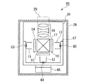
また、ベースプレート20に搭載された各部材を覆うように筐体26が配設され、この筐体26はベースプレート20に固定されている。筐体26には、吸気及び排気用の開口(吸気孔27、排気孔28)が設けられている。本例では、吸気孔27は、ヒートシンク41,42,43の放熱面に対向する筐体26の側面に設けられ、排気孔28は筐体26の上面のうちのヒートシンク41,42,43の上方位置に設けられている。なお、投射系18は、鏡筒29内に保持されている。
【0051】
図11は、上述した冷却装置40の動作を説明するための図であり、(a)は光源温度が低い状態、(b)は光源温度が高い状態を示している。なお、図11では、説明の簡単のため、光源12に関する構成について代表的に示している。
【0052】
図11(a)に示すように、例えば電源投入前など、光源12の温度が室温に近い低い状態では、バイアスバネ48のばね定数に比べて、形状記憶合金バネ45のばね定数が小さくなる(バイアスバネ>形状記憶合金バネ)。そのため、バイアスバネ48が伸長し、形状記憶合金バネ45がバイアスバネ48のばね力(付勢力)に負けて収縮する。つまり、バイアスバネ48が、ヒートシンク42と形状記憶合金バネ45を押しつけ、ヒートシンク42と伝熱部材51とが互いに離れた状態となる。
【0053】
図11(b)に示すように、例えば電源投入後など、光源12が発熱して温度上昇すると、光源12の熱が伝熱部材51等を介して、形状記憶合金バネ45に伝わる。形状記憶合金バネ45が高温になると、形状記憶合金バネ45のばね定数が急激に増加し、バイアスバネ48のばね定数に比べて、形状記憶合金バネ45のばね定数が大きくなる(バイアスバネ<形状記憶合金バネ)。その結果、形状記憶合金バネ45が伸長し、バイアスバネ48が収縮する。そして、形状記憶合金バネ45のばね力により、ヒートシンク42が光源12の側に移動し、ヒートシンク42の吸熱面と伝熱部材51とが直接接触する。ヒートシンク42と伝熱部材51とが直接接することにより、伝熱面積が増え、光源12の熱が伝熱部材51を介してヒートシンク42により多く移動し、その熱がヒートシンク42を介して放熱される。つまり、光源12からの放熱量が増加する。
【0054】
続いて、光源12が放熱によって十分に冷却され、それに伴って伝熱部材51、及び形状記憶合金バネ45が低温になると、形状記憶合金バネ45のばね定数が急激に減少し、バイアスバネ48のばね定数に比べて、 形状記憶合金バネ45のばね定数が小さくなる(バイアスバネ>形状記憶合金バネ)。その結果、図11(a)に示すように、バイアスバネ48が伸長し、形状記憶合金バネ45が収縮する。そして、ヒートシンク42が光源12から離れる側に移動し、ヒートシンク42の吸熱面と伝熱部材51とが離れる。ヒートシンク42と伝熱部材51とが離れることにより、光源12からの放熱量が減少する。
【0055】
以後、同様の動作が繰り返されることにより、光源12が所望の温度範囲に保たれる。つまり、上記構成の冷却装置40では、光源12の温度が高い場合には、ヒートシンク42と伝熱部材51とが直接接することで伝熱面積が増えて光源12からの放熱量が多くなり、光源12の温度上昇が抑制される。一方、光源12の温度が低い場合には、ヒートシンク42と伝熱部材51とが離れることで光源12からの放熱量が少なくなり、温度降下が抑制される。この繰り返しにより、光源12の温度が所望の温度範囲内に保たれる。光源11,13についてもこれと同様である。
【0056】
このように、本例のプロジェクタ10では、光源の温度に応じて光源からの放熱量が切り換えられ、これにより光源の温度変化が抑制される。そのため、投射画像の品質安定性の向上が図られる。
【0057】
また、本例のプロジェクタ10では、放熱量の切り換えを、形状記憶合金バネの物理的な特性を利用して行っている。そのため、構成の簡素化とともに、消費電力の軽減化が図られる。
【0058】
なお、上記冷却装置40において、 光源が十分に冷却された温度に対して、形状記憶合金バネのばね定数が急激に減少する際の温度が小さい場合には、ヒートシンクと伝熱部材は接触したままとなり、光源の温度は十分に冷却された温度で安定する。
【0059】
また、本例のプロジェクタ10において、光源11,12,13の温度に応じて、筐体26に設けられる開口(吸気孔27、排気孔28など)の開口度を制御して放熱量を変化させてもよい。
【0060】
また、このプロジェクタ10では、図12に示すように、発熱体のひとつである電源ユニット32(ACアダプタ)が、筐体26(プロジェクタ本体)の外部に配されている。これにより、筐体26内の発熱量が抑制され、光学特性に与える熱影響がさらに抑制される。
【0061】
次に、本発明のプロジェクタの他の実施の形態例について図13及び図14を参照して説明する。なお、先の実施形態例と同一の機能を有する構成要素は同一の符号を付し、その説明を省略または簡略化する。
【0062】
図13及び図14において、プロジェクタ60は、先の図9及び図10に示したプロジェクタ10と異なり、冷却手段としての冷却ファン61を有する冷却装置62を備えている。また、冷却装置62は、光源11,12,13の温度を計測する温度センサ63,64,65と、温度センサ63,64,65の計測結果に基づいて、冷却ファン61の作動状態を制御する制御系66(制御回路)とを有している。
【0063】
各光源11,12,13は、良熱伝導体(例えばアルミニウム材)からなる伝熱部材67を介して一のヒートシンク68に熱的に接続されている。
【0064】
冷却ファン61は、伝熱部材67及びヒートシンク68を介して放熱される光源11,12,13の熱を、ヒートシンク68の周辺から空気とともに排除するとともに、その空気を筐体26の内部から外部に排気孔28を介して排出するものである。本例では、冷却ファン61は、排気孔28の近傍(下方位置)に配置されている。
【0065】
温度センサ63,64,65としては、例えば、抵抗値が温度によって変化する抵抗サーミスタ、熱電対などが挙げられる。温度センサ63,64,65の電気信号は、制御系66に送られる。
また、制御系66は、温度センサ63,64,65からの信号に基づいて冷却ファン61の作動状態(運転/非運転、回転数など)を制御するものである。
【0066】
上記構成のプロジェクタ60では、冷却ファン61を作動させることで光源11,12,13からの放熱量が多くなり、冷却ファン61を停止させることで光源11,12,13からの放熱量が少なくなる。したがって、光源11,12,13の温度が高い場合には冷却ファン61を作動し、光源11,12,13の温度が低い場合には冷却ファン61を停止させることにより、光源11,12,13の温度変化が抑制される。
【0067】
例えば、電源投入時には、冷却ファン61は停止状態にある。電源投入後、光源11,12,13は、発熱して温度が上昇する。このとき、冷却ファン61が停止状態にあるので、光源11,12,13からの放熱量は少なく、光源11,12,13は速やかに温度上昇する。
【0068】
続いて、制御系66は、温度センサ63,64,65の計測結果に基づいて、光源11,12,13が所定の温度(ランプ許容温度範囲)に達すると、冷却ファン61の作動(回転)を開始する。
冷却ファン61の作動により、ヒートシンク68を介した光源11,12,13からの放熱量が多くなり、光源11,12,13が冷却されて温度降下する。その後、光源11,12,13の発熱量とヒートシンク68を介した放熱量とが釣り合うことにより、光源11,12,13の温度が飽和温度で安定する。
【0069】
ここで、本例では、光源11,12,13の温度上昇の過程において、冷却ファン61の作動を開始するとき、熱的な遅れ(応答遅れ)が生じることから、冷却ファン61の作動の開始のタイミングは、この応答遅れを考慮して設定されてもよい。
【0070】
すなわち、冷却ファン61を作動させると、まず、ヒートシンク68の放熱効果が高まるのでヒートシンク68が冷却され、その後、伝熱部材67、光源11,12,13の順に冷却される。つまり、冷却ファン61の作動を開始した時点から遅れて光源11,12,13が冷却される。この応答遅れのために、光源11,12,13は、冷却ファン61の作動を開始した時点からしばらくの間は温度上昇を続け(オーバーシュート)、一定時間経過後に温度降下をはじめる。過度な温度上昇(オーバーシュート)がランプ許容温度範囲を超えるような場合には、上記応答遅れに基づいて、冷却ファン61の作動開始のタイミングを少し早めることにより、過度な温度変化が抑制される。
【0071】
なお、光源11,12,13の温度変化が互いに異なる場合には、例えば、一つの光源が所定の温度(ランプ許容温度範囲)に達した時点で冷却ファン61の作動を開始させるとよい。
【0072】
また、ここでは、冷却ファン61を停止状態と作動状態との間で切り換えて放熱量を変化させる場合について説明したが、光源11,12,13の温度に基づいて、冷却ファン61の回転数を変化させてもよい。
【0073】
また、本例では、プロジェクタ60に使用時において、ベースプレート20は、ライトバルブ14,15,16、プリズム17、及び投射系18などの各光学部材に対して上方に位置する。この構成では、ベースプレート20に対して光学部材が下方に配される一方で、発熱体で暖められた空気が上方に移動する。そのため、上記各光学部材の温度上昇が抑制され、それに伴う個々の光学特性の低下が抑制される。
【0074】
また、ベースプレート20として、熱伝導率が高い材質からなる熱良導体を用いてもよい。この場合、ベースプレート20における温度ムラが少なくなり、光源11,12,13、及びライトバルブ14,15,16などの発熱体の熱影響による、ライトバルブ14,15,16、プリズム17、及び投射系18などの各光学部材の光学特性の低下が抑制される。そのため、発熱に伴う投射画像の劣化がさらに少なくなり、小型化により好ましく適用される。熱良導体としては、例えば、アルミニウム材あるいはその合金の他、銅、黄銅、金、鉄(及び鋼)、ニッケルなどの各種金属及びその合金が用いられる。
【0075】
また、ライトバルブ14,15,16、プリズム17、及び投射系18の各光学部材とベースプレート20との間に、断熱部材を配してもよい。この場合、ベースプレート20から各光学部材のそれぞれへの熱伝達が抑制され、各光学部材の個々の光学特性の低下が抑制される。
【0076】
【実施例】
次に、上述した実施の形態例のプロジェクタの冷却効果を調べた。
まず、先の図9及び図10に示すプロジェクタについて調べた。なお、プロジェクタを製作するにあたっては、光源(LEDランプ)の許容温度範囲について調べた。
【0077】
(LEDランプの許容温度範囲について)
前述したように、光源として使用するLEDランプは光強度や光波長に温度依存性があることから、使用温度によって投射画像の品質が変化する。そのため、使用するLEDランプの許容温度範囲について調べた。
LEDランプの許容温度範囲については、(1)使用するLEDランプの種類によって異なる、(2)製作するプロジェクタの用途によって変わる(すなわち、使用環境の明るさ、及び、投影画像の種類が大きく影響する因子である)、(3)温度変化によって画質が変化するのをどこまで許容するかは顧客の判断に依存する、などの条件が含まれる。
そこで、以下の手順に基づいてLEDランプの許容温度範囲を決定した。
【0078】
(実験用プロジェクタの構成)
図15及び図16に実験用プロジェクタの概略図を示す。なお、先の図9及び図10に示すプロジェクタと同一の機能を有する構成要素は同一の符号を付し、その説明を省略または簡略化する。
この実験用プロジェクタは、先の図9及び図10に示すプロジェクタ10における伝熱部材50,51,52とヒートシンク41,42,43とが常に接触している状態と同様の形態に構成されている。
光源11,12,13としては、先の図9及び図10に示すプロジェクタと同一のLEDランプ(LumiLeds社製のLuxeonシリーズ)を用いた。
この実験用プロジェクタでは、ヒートシンクから大気中への熱抵抗を変えることにより、すなわち、ヒートシンクの大きさを変えることにより、LEDランプの飽和上昇温度を変えることが出来る。
【0079】
(LEDランプの許容温度範囲を求める)
図15及び図16に示す実験用プロジェクタを用い、ヒートシンクの大きさ、使用環境の明るさが異なる水準について、画質評価を行った。環境温度は25℃に保った。
まずは、画質評価の基準条件を決める。
今回のプロジェクタが目指している使用環境の明るさは1000ルックス(労働基準法の精密作業推奨基準)である。
図15及び図16の実験用プロジェクタになるべく大きなヒートシンクを取り付け、1000ルックスの環境下でスクリーンに市松模様を投影し(図17参照)、白色部は白色光になるように、黒色部は色あせないように、各色LEDに流す電流値を調整した(この電流調整値は以降の実験において固定)。
またそのときの、消費電力(印加電圧×電流)から25℃での各色LEDの飽和温度上昇が連続使用時許容最大温度(今回のLEDは90℃)になるようにヒートシンクの大きさを設計した。
このヒートシンクの大きさを基準とし、以降の実験は、これより大きなヒートシンクの水準を振って行う。
なお、各色LEDランプには熱電対を貼り付け発熱温度を測定した。
使用環境の明るさは30ルックス(月の明るさ)、70ルックス(労働基準法の雑作業用照明基準)、150ルックス(普通作業)、300ルックス(精密作業)、1000ルックス(精密作業推奨基準)の5水準とした。
【0080】
画質評価は以下のように行った。
(a)試験者として18歳から60歳までの男女を年齢、性別をランダムに50名ほど選出した。
(b)評価した投影画像は文字、グラフからなる静止画像、及び、風景の静止画像、アニメ動画、実写動画の4種類である。
(c)良好から明確に画質劣化が見られる(色あせて見えない、または、明確に色バランスがずれている等)までの5段階評価をしてもらい、平均をとり、5から4までを良好(記号○)、4未満3以上をやや不良(記号△)、3未満を不良(記号×)とした。
【0081】
画質評価の結果を図18の表に示す。なお、図18の表には各色LEDの温度も併記する。
今回のプロジェクタは、(1)使用しているLEDランプがLumiLeds社製のLuxeonシリーズである、(2)使用環境の明るさは1000ルックス(労働基準法の精密作業推奨基準)である、(3)実写動画まで高画質を確保する、ものである。
そのため、図18の表より、LEDランプの許容温度範囲は90℃〜53℃となる。なお、30ルックスの明るさで主に使用し、ビジネスプレゼンテーション用に風景静止画まで高画質を確保すれば十分なプロジェクタを作るとすれば、LEDランプの許容温度範囲は90℃〜27℃となる。
【0082】
(ヒートシンクの設定)
同一ヒートシンクにおいて、環境温度が変化すると、LEDランプの飽和上昇温度も変化する。
今回のプロジェクタでは、動作補償範囲は10℃〜35℃環境温度としており、10℃のときが最もLEDランプの飽和上昇温度が低くなる。また、図18の表は環境温度25℃のデータであるので、ts:所定ヒートシンク使用時のLEDランプの飽和上昇温度、te:測定時の環境温度、tcs(L):動作補償温度の下限、td(L):LEDランプの許容温度下限、とすると、
ts−te+tcs(L)>td(L)
であるから、
ts−25+10>53
となり、次式(1)が得られる。
ts>68(℃)…(1)
【0083】
一方、35℃のときが最もLEDランプの飽和上昇温度が高くなるので、ts:所定ヒートシンク使用時のLEDランプの飽和上昇温度、te:測定時の環境温度、tcs(U):動作補償温度の上限、td(U):LEDランプの許容温度上限、とすると、
ts−te+tcs(U)<td(U)
であるから、
ts−25+35<90
となり、次式(2)が得られる。
ts<80(℃)…(2)
よって、式(1)及び式(2)、並びに図18の表より、ヒートシンクA、ヒートシンクBが選択される。
【0084】
(形状記憶合金バネの設定)
図19に示したように、形状記憶合金バネのばね定数温度依存性はヒステリシスになる場合が多い。したがって、図19の温度MsがLEDランプの許容温度下限(53℃)よりも大きくなるような形状記憶合金バネを選択する。
ここでは、Ms=55℃、As=60℃の形状記憶合金バネを選択した。
【0085】
(オーバーシュートの確認)
(実施例1)
次に、先の図9及び図10に示したプロジェクタに、上述の形状記憶合金バネを設置し、ヒートシンクをヒートシンクA、ヒートシンクBの2水準を取り付け、プロジェクタの動作補償下限10℃と上限35℃の2水準について、電源投入後の各色LEDランプの温度を測定した。
【0086】
図20にヒートシンクB、環境温度10℃での電源投入直後からの各色LEDランプの温度変化を示す。
各色LEDランプは環境温度10℃から電源を投入すると発熱を開始し温度が上昇する。そして、時間[Tw1]後にLEDランプ許容温度下限の53℃に達する。
次に、時間[Tc1]後に各色LEDランプ温度が60℃に達するとやや遅れて形状記憶合金バネが60℃になる。その結果、ヒートシンクが伝熱部材を介して各色LEDランプに接触する。
この時間遅れのために各色LEDランプ温度は60℃よりもΔt1だけ温度上昇(オーバーシュート)してから温度が低下し始める。
図18の表より、ヒートシンクBの環境温度25℃でのLEDランプ飽和温度上昇は69℃であった。したがって、環境温度が10℃になるとLEDランプ飽和温度上昇は54℃になる。すなわち、各色LEDランプ温度は54℃まで低下しようとする。
各色LEDランプ温度が低下し55℃に達するとやや遅れて形状記憶合金バネが55℃になる。その結果、ヒートシンクと伝熱部材は離接する。
この時間遅れのために各色LEDランプ温度は54℃まで低下してから温度が上昇し始める。
以降、各色LEDランプ温度は54℃から 60+Δt1(℃) の間を上下する。
ここで、LEDランプ、伝熱部材、ヒートシンク、形状記憶合金バネなどの条件(特性)によっては、オーバーシュートによりLED許容温度上限を超える場合がある。そのため、As:形状記憶合金バネの低温から高温に向かう時にバネ定数が増加し始める温度(図19参照)、td(U):LEDランプの許容温度上限、とするとき、
As+Δt1≦td(U)
となるように設計を行い、かつ、実験で確認しておく必要がある。
【0087】
図21にヒートシンクB、環境温度35℃での電源投入直後からの各色LEDランプの温度変化を示す。
図21に示すように、各色LEDランプは環境温度35℃から電源を投入すると発熱を開始し温度が上昇する。そして、時間[Tw2]後にLEDランプ許容温度下限の53℃に達する。
次に、時間[Tc2]後に各色LEDランプ温度が60℃に達するとやや遅れて形状記憶合金バネが60℃になる。その結果、ヒートシンクが伝熱部材を介して各色LEDランプに接触する。
ここで、図18の表より、ヒートシンクBの環境温度25℃でのLEDランプ飽和温度上昇は69℃であった。したがって、環境温度が35℃になるとLEDランプ飽和温度上昇は79℃になる。
よって、時間遅れのために各色LEDランプ温度は60℃を超えても上昇するが、LEDランプ飽和温度上昇の方が79℃と高いので、単調に79℃に達し安定する。
以上、説明したようにヒートシンクBを使用すれば、環境温度10℃〜35℃において、各色LEDランプは許容温度範囲に入る。
その時の、プロジェクタのウオームアップ時間は Tw2〜Tw1 である。
【0088】
図22にヒートシンクA、環境温度10℃での電源投入直後からの各色LEDランプの温度変化を示す。
各色LEDランプは環境温度10℃から電源を投入すると発熱を開始し温度が上昇する。そして、時間[Tw3]後にLEDランプ許容温度下限の53℃に達する。
次に、時間[Tc3]後に各色LEDランプ温度が60℃に達するとやや遅れて形状記憶合金バネが60℃になる。その結果、ヒートシンクが伝熱部材を介して各色LEDランプに接触する。
この時間遅れのために各色LEDランプ温度は60℃よりもΔt2だけ温度上昇(オーバーシュート)してから温度が低下し始める。
図18の表より、ヒートシンクAの環境温度25℃でのLEDランプ飽和温度上昇は80℃であった。したがって、環境温度が10℃になるとLEDランプ飽和温度上昇は65℃になる。
すなわち、各色LEDランプ温度は65℃まで低下して安定する。
ヒートシンクは伝熱部材を介して各色LEDランプに当接したままである。
ここで、LEDランプ、伝熱部材、ヒートシンク、形状記憶合金バネなどの条件によってオーバーシュートによりLED許容温度上限を超える場合がある。そのため、As:形状記憶合金バネの低温から高温に向かう時にバネ定数が増加し始める温度(図19参照)、td(U):LEDランプの許容温度上限、とするとき、
As+Δt2≦td(U)
となるように設計を行い、かつ、実験で確認しておく必要がある。
【0089】
図23にヒートシンクA、環境温度35℃での電源投入直後からの各色LEDランプの温度変化を示す。
各色LEDランプは環境温度35℃から電源を投入すると発熱を開始し温度が上昇する。そして、時間[Tw4]後にLEDランプ許容温度下限の53℃に達する。
次に、時間[Tc4]後に各色LEDランプ温度が60℃に達するとやや遅れて形状記憶合金バネが60℃になる。その結果、ヒートシンクが伝熱部材を介して各色LEDランプに接触する。
ここで、図18の表より、ヒートシンクAの環境温度25℃でのLEDランプ飽和温度上昇は80℃であった。したがって、環境温度が35℃になるとLEDランプ飽和温度上昇は90℃になる。
よって、時間遅れのために各色LEDランプ温度は60℃を超えても上昇するが、LEDランプ飽和温度上昇の方が90℃と高いので、単調に90℃に達し安定する。
以上、説明したようにヒートシンクAを使用すれば、環境温度10℃〜35℃において、各色LEDランプは許容温度範囲に入る。
その時の、プロジェクタのウオームアップ時間は Tw4〜Tw3 である。
【0090】
(比較例1)
次に、従来の形態のプロジェクタについても同様の評価を行った。
先の図15及び図16に示した実験用プロジェクタに、ヒートシンクA、ヒートシンクBの2水準を取り付け、プロジェクタの動作補償下限10℃と上限35℃の2水準について、電源投入後の各色LEDランプの温度を測定した(比較例1)。
この比較例1に使用する実験用プロジェクタは、先の図9及び図10に示すプロジェクタと異なり、伝熱部材とヒートシンクとが常に接した状態にあり、光源からの放熱量(冷却効率)は一定である。
【0091】
図24に比較例1のヒートシンクB、環境温度10℃での電源投入直後からの各色LEDランプの温度変化を示す。
各色LEDランプは環境温度10℃から電源を投入すると発熱を開始し温度が上昇する。そして、時間[Tw5]後にLEDランプ許容温度下限の53℃に達する。
ここで、図18の表より、ヒートシンクBの環境温度25℃でのLEDランプ飽和温度上昇は69℃であった。したがって、環境温度が10℃になるとLEDランプ飽和温度上昇は54℃になる。
よって、各色LEDランプ温度は54℃まで上昇して安定する。
【0092】
図25に比較例1のヒートシンクB、環境温度35℃での電源投入直後からの各色LEDランプの温度変化を示す。
各色LEDランプは環境温度35℃から電源を投入すると発熱を開始し温度が上昇する。そして、時間[Tw6]後にLEDランプ許容温度下限の53℃に達する。
ここで、図18の表より、ヒートシンクBの環境温度25℃でのLEDランプ飽和温度上昇は69℃であった。したがって、環境温度が35℃になるとLEDランプ飽和温度上昇は79℃になる。
よって、各色LEDランプ温度は79℃まで上昇して安定する。
【0093】
図26に比較例のヒートシンクA、環境温度10℃での電源投入直後からの各色LEDランプの温度変化を示す。
各色LEDランプは環境温度10℃から電源を投入すると発熱を開始し温度が上昇する。そして、時間[Tw7]後にLEDランプ許容温度下限の53℃に達する。
ここで、図18の表より、ヒートシンクAの環境温度25℃でのLEDランプ飽和温度上昇は80℃であった。したがって、環境温度が10℃になるとLEDランプ飽和温度上昇は65℃になる。
よって、各色LEDランプ温度は65℃まで上昇して安定する。
【0094】
図27に比較例のヒートシンクA、環境温度35℃での電源投入直後からの各色LEDランプの温度変化を示す。
各色LEDランプは環境温度35℃から電源を投入すると発熱を開始し温度が上昇する。そして、時間[Tw8]後にLEDランプ許容温度下限の53℃に達する。
ここで、図18の表より、ヒートシンクAの環境温度25℃でのLEDランプ飽和温度上昇は80℃であった。したがって、環境温度が35℃になるとLEDランプ飽和温度上昇は90℃になる。
よって、各色LEDランプ温度は90℃まで上昇して安定する。
【0095】
上記の実施例1及び比較例1における評価から次のことがわかった。
ヒートシンクを適切に設計することにより、図8及び図9に示すプロジェクタ(実施例1)、及び図15及び図16に示す実験用プロジェクタ(比較例1)のいずれも、LEDランプ許容温度範囲内に各色LEDランプ温度を収めることはできることがわかった。
しかしながら、本発明の実施の形態例である、図8及び図9に示すプロジェクタ(実施例1)では、電源投入直後から高温になるまでの間、ヒートシンクと伝熱部材とを非接触とすることにより、各色LEDランプ発熱の放熱量を減少させ、温度上昇速度を大きくすることができる。
その結果、電源投入後から投射画像の品質が安定するまでの待機時間(ウオームアップ時間)を短縮することができる(Tw1<Tw5、Tw2<Tw6、Tw3<Tw7、Tw4<Tw8)。
【0096】
(実施例2)
次に、上述した実施例1と同様に、先の図9及び図10に示したプロジェクタに、ヒートシンクC,D,E,F,Gを使用した場合について評価した(実施例2)。
つまり、実施例1ではヒートシンクA、ヒートシンクBを使用したが、本例では、ts:所定ヒートシンク使用時のLEDランプの飽和上昇温度、te:測定時の環境温度、tcs(L):動作補償温度の下限、td(L):LEDランプの許容温度下限、とするとき、
ts−te+tcs(L)<td(L)
となる、ヒートシンクC,D,E,F,Gを使用した場合を説明する。
すなわち、本例では、
Ts−25+10<53
となり、次式(3)が得られる。
Ts<68(℃)…(3)
以下、代表してヒートシンクCを用いた場合について説明する。
なお、形状記憶合金バネはMs=60℃、As=70℃(図19参照)の形状記憶合金バネを選択した。
【0097】
先の図9及び図10に示すプロジェクタに上述の形状記憶合金バネを設置し、ヒートシンクCを取り付け、プロジェクタの動作補償下限10℃と上限35℃の2水準について、電源投入後の各色LEDランプの温度を測定した。
【0098】
図28にヒートシンクC、環境温度10℃での電源投入直後からの各色LEDランプの温度変化を示す。
各色LEDランプは環境温度10℃から電源を投入すると発熱を開始し温度が上昇する。そして、時間[Tw9]後にLEDランプ許容温度下限の53℃に達する。
次に、時間[Tc9]後に各色LEDランプ温度が70℃に達するとやや遅れて形状記憶合金バネが70℃になる。その結果、ヒートシンクが伝熱部材を介して各色LEDランプに接触する。
この時間遅れのために各色LEDランプ温度は70℃よりもΔt3だけ温度上昇(オーバーシュート)してから温度が低下し始める。
図18の表より、ヒートシンクCの環境温度25℃でのLEDランプ飽和温度上昇は62℃であった。したがって、環境温度が10℃になるとLEDランプ飽和温度上昇は47℃になる。すなわち、各色LEDランプ温度は47℃まで低下しようとする。
各色LEDランプ温度が低下し60℃に達するとやや遅れて形状記憶合金バネが60℃になる。その結果、ヒートシンクと伝熱部材は離接する。
この時間遅れのために各色LEDランプ温度はΔt4まで低下(アンダーシュート)してから温度が上昇し始める。
以降、各色LEDランプ温度は60℃−Δt4(℃)から70+Δt3(℃)の間を上下する。
ここで、LEDランプ、伝熱部材、ヒートシンク、形状記憶合金バネなどの条件によってオーバーシュートによりLED許容温度上限を超える場合がある。そのため、As:形状記憶合金バネの低温から高温に向かう時にバネ定数が増加し始める温度(図19参照)、td(U):LEDランプの許容温度上限、とするとき、
As+Δt3≦td(U)
となるように設計を行い、かつ、実験で確認しておく必要がある。
かつ、アンダーシュートによりLED許容温度下限を超える場合があるので、Ms:高温から低温に向かう時にバネ定数が減少し始める温度(図19参照)、td(L):LEDランプの許容温度下限、とするとき、
Ms−Δt4≧td(L)
となるように設計を行い、かつ、実験で確認しておく必要がある。
【0099】
図29にヒートシンクC、環境温度35℃での電源投入直後からの各色LEDランプの温度変化を示す。
各色LEDランプは環境温度35℃から電源を投入すると発熱を開始し温度が上昇する。そして、時間[Tw10]後にLEDランプ許容温度下限の53℃に達する。
次に、時間[Tc10]後に各色LEDランプ温度が70℃に達するとやや遅れて形状記憶合金バネが70℃になる。その結果、ヒートシンクが伝熱部材を介して各色LEDランプに接触する。
この時間遅れのために各色LEDランプ温度は70℃よりもΔt5だけ温度上昇(オーバーシュート)してから温度が低下し始める。
図18の表より、ヒートシンクCの環境温度25℃でのLEDランプ飽和温度上昇は62℃であった。したがって、環境温度が35℃になるとLEDランプ飽和温度上昇は72℃になる。
すなわち、各色LEDランプ温度は72℃まで低下して安定する。
ヒートシンクは伝熱部材を介して各色LEDランプに当接したままである。
ここで、LEDランプ、伝熱部材、ヒートシンク、形状記憶合金バネなどの条件によってオーバーシュートによりLED許容温度上限を超える場合がある。そのため、As:形状記憶合金バネの低温から高温に向かう時にバネ定数が増加し始める温度(図19参照)、td(U):LEDランプの許容温度上限、とするとき、
As+Δt5≦td(U)
となるように設計を行い、かつ、実験で確認しておく必要がある。
【0100】
(比較例2)
先の図15及び図16に示した実験用プロジェクタに、ヒートシンクCを取り付け、プロジェクタの動作補償下限10℃と上限35℃の2水準について、電源投入後の各色LEDランプの温度を測定した(比較例2)。
図15、図16は図9、図10に示すプロジェクタと異なり、常に伝熱部材を介してヒートシンクを各色LEDに接続し、冷却効率を一定とした構成である。
この比較例2に使用する実験用プロジェクタは、先の図9及び図10に示すプロジェクタと異なり、伝熱部材とヒートシンクとが常に接した状態にあり、光源からの放熱量(冷却効率)は一定である。
【0101】
図30に比較例2のヒートシンクB、環境温度10℃での電源投入直後からの各色LEDランプの温度変化を示す。
各色LEDランプは環境温度10℃から電源を投入すると発熱を開始し温度が上昇する。図18の表より、ヒートシンクCの環境温度25℃でのLEDランプ飽和温度上昇は62℃であった。したがって、環境温度が10℃になるとLEDランプ飽和温度上昇は47℃になる。
よって、各色LEDランプ温度は47℃で安定してしまい、LEDランプ許容温度下限値にも達しない。
【0102】
図31に比較例のヒートシンクC、環境温度35℃での電源投入直後からの各色LEDランプの温度変化を示す。
各色LEDランプは環境温度35℃から電源を投入すると発熱を開始し温度が上昇する。そして、時間[Tw11]後にLEDランプ許容温度下限の53℃に達する。
ここで、図18の表より、ヒートシンクCの環境温度25℃でのLEDランプ飽和温度上昇は62℃であった。したがって、環境温度が35℃になるとLEDランプ飽和温度上昇は72℃になる。
よって、各色LEDランプ温度は72℃まで上昇して安定する。
【0103】
上記の実施例2及び比較例2における評価から次のことがわかった。
各色LEDランプ温度について、図15及び図16に示す実験用プロジェクタ(比較例2)では許容温度範囲内に収まらないのに対して、本発明の実施の形態例である、図8及び図9に示すプロジェクタ(実施例2)では、許容温度範囲内に収めることができる。
また、実施例2では、電源投入直後から高温になるまでの間、ヒートシンクと伝熱部材とを非接触とすることにより、各色LEDランプ発熱の放熱量を減少させ、温度上昇速度を大きくすることができる。
その結果、電源投入後から投射画像の品質が安定するまでの待機時間(ウオームアップ時間)を短縮することができる(Tw10<Tw11;図29及び図31参照)。
【0104】
(実施例3)
次に、先の図13及び図14に示したプロジェクタについて上記と同様の評価を行った(実施例3)。
図32に実施例3のプロジェクタの各色LEDランプの温度変化を示す。
各色LEDランプは環境温度(動作補償温度範囲内10℃〜35℃)から電源を投入すると発熱を開始し温度が上昇する。そして、時間[Tw12]後にLEDランプ許容温度下限の53℃に達する。
次に、時間[Tc12]後に各色LEDランプ温度が回転温度に達すると(温度検出素子で検出)、冷却ファン制御回路により冷却ファンの回転が開始される。
冷却ファンの回転により、ヒートシンクを通過する風量が増加する。そして、ヒートシンクが冷却され、伝熱部材が冷却され、遅れて各色LEDランプが冷却され始める。
この冷却遅れのために各色LEDランプ温度は回転温度よりもΔt6だけ温度上昇(オーバーシュート)してから温度が低下し始める。
各色LEDランプの発熱とヒートシンクの放熱が釣り合うと温度低下はなくなり、各色LEDランプの温度は飽和温度で安定する。
【0105】
ここで、(1)(回転温度)+Δt6≦(LEDランプの許容温度上限)、(2)(LEDランプの許容温度下限)≦(飽和温度)≦(LEDランプの許容温度上限)、となるように設計を行い、かつ、実験で確認しておく必要がある。
また、LEDランプは複数有り、同一の温度変化を示さない場合もある。したがって、冷却ファンの回転開始は、少なくとも一つのLEDランプが先に回転温度に達した時に行う必要がある。
【0106】
(比較例3)
次に、先の図13及び図14に示したプロジェクタについて放熱量を一定とした場合の評価を行った(比較例3)。
すなわち、比較例3として図13及び図14に示すプロジェクタで、電源投入直後から冷却ファンを回転させた場合、すなわち、放熱量(冷却効率)を一定とした場合の各色LEDランプの温度変化を調べた。なお、比較例3では温度検出素子(温度センサ)は不要、冷却ファン制御回路(制御系)も不要である。
温度の計測結果を図33に示す。
【0107】
各色LEDランプは図32と同一の環境温度から電源を投入すると発熱を開始し温度が上昇する。そして、時間[Tw13]後にLEDランプ許容温度下限の53℃に達する。
その後、各色LEDランプの発熱とヒートシンクの放熱が釣り合うと温度上昇はなくなり、各色LEDランプの温度は図32と同一の飽和温度で安定する。
【0108】
上記の実施例3及び比較例3における評価から次のことがわかった。
図32に示す実施例3及び図33に示す比較例3のいずれも、LEDランプ許容温度範囲内に各色LEDランプ温度を収めることはできる。
しかしながら、本発明の実施の形態例である、図13及び図14に示したプロジェクタでは、電源投入直後から高温になるまで冷却ファンを停止させることにより(実施例3)、各色LEDランプ発熱の放熱量を減少させ、温度上昇速度を大きくすることができる。
その結果、電源投入後から投射画像の品質が安定するまでの待機時間(ウオームアップ時間)を短縮することができる(Tw12<Tw13)を短縮することができる。
【0109】
以上、添付図面を参照しながら本発明に係る好適な実施形態について説明したが、本発明は係る例に限定されないことは言うまでもない。上述した例において示した各構成部材の諸形状や組み合わせ等は一例であって、本発明の主旨から逸脱しない範囲において設計要求等に基づき種々変更可能である。
【図面の簡単な説明】
【図1】本発明のプロジェクタ及びその冷却方法を概念的に示す図。
【図2】LEDの発光強度の温度依存性(温度−光強度比率)を示す図。
【図3】LEDの発光強度分布の温度依存性(光の波長−光強度分布)を示す図。
【図4】LED光源における、電源投入後のLEDの温度変化の様子を示す図。
【図5】放熱量の切り換えを行う場合の電源投入直後からの光源の温度変化の様子(実線)を示す図。
【図6】応答遅れを含む光源の温度変化の様子の例を示す図。
【図7】応答遅れを含む光源の温度変化の様子の他の例を示す図。
【図8】液晶プロジェクタの概略的な全体構成を模式的に示す図。
【図9】プロジェクタにおける各構成部材の配置の様子を模式的に示す平面図。
【図10】プロジェクタにおける各構成部材の配置の様子を模式的に示す側面図。
【図11】冷却装置の動作を説明するための図であり、(a)は光源温度が低い状態、(b)は光源温度が高い状態を示している。
【図12】電源ユニットの配置図。
【図13】本発明のプロジェクタの他の実施の形態例について各構成部材の配置の様子を模式的に示す平面図。
【図14】本発明のプロジェクタの他の実施の形態例について各構成部材の配置の様子を模式的に示す側面図。
【図15】評価用のプロジェクタ(実験用プロジェクタ)を模式的に示す平面図。
【図16】評価用のプロジェクタ(実験用プロジェクタ)を模式的に示す側面図。
【図17】画質評価に用いた市松模様を説明するための図。
【図18】画質評価の結果の表を示す図。
【図19】形状記憶合金バネのヒステリシスを説明するための図。
【図20】実施例1におけるLEDランプの温度変化を示す図。
【図21】実施例1におけるLEDランプの温度変化を示す図。
【図22】実施例1におけるLEDランプの温度変化を示す図。
【図23】実施例1におけるLEDランプの温度変化を示す図。
【図24】比較例1におけるLEDランプの温度変化を示す図。
【図25】比較例1におけるLEDランプの温度変化を示す図。
【図26】比較例1におけるLEDランプの温度変化を示す図。
【図27】比較例1におけるLEDランプの温度変化を示す図。
【図28】実施例2におけるLEDランプの温度変化を示す図。
【図29】実施例2におけるLEDランプの温度変化を示す図。
【図30】比較例2におけるLEDランプの温度変化を示す図。
【図31】比較例2におけるLEDランプの温度変化を示す図。
【図32】実施例3におけるLEDランプの温度変化を示す図。
【図33】比較例3におけるLEDランプの温度変化を示す図。
【符号の説明】
1,10,60…プロジェクタ、2,11,12,13…光源(発熱体)、3,40,62…冷却装置、4…第1の冷却手段、5…第2の冷却手段、6…切換手段、14,15,16…ライトバルブ、17…プリズム、18…投射系、20…ベースプレート、21…駆動回路、41,42,43,68…ヒートシンク(放熱体)、44,45,46…形状記憶合金バネ(切換手段)、47,48,49…バイアスバネ、50,51,52,67…伝熱部材、61…冷却ファン、63,64,65…温度センサ、66…制御系(制御手段)。[0001]
TECHNICAL FIELD OF THE INVENTION
The present invention relates to a projector having a light source for projection light, and more particularly to a method for cooling a projector.
[0002]
[Prior art]
2. Description of the Related Art Conventionally, as one of display devices in electronic devices, a projector as a projection display device that enlarges and projects an image of a video source onto a screen via an optical system has been known.
[0003]
Since the projector has devices that easily generate heat, such as a light source and a power supply unit, when the heat of these heating elements is transmitted to the optical members on the optical path, it affects the mounting accuracy and thermal characteristics of the optical members, There is a possibility that the optical characteristics are degraded.
[0004]
As a technique related to a heat countermeasure of a projector, for example, there is a technique in which a radiator such as a heat sink is attached to an optical member having a high temperature to dissipate heat (for example, see Patent Document 1).
[0005]
[Patent Document 1]
JP-A-14-009937
[0006]
[Problems to be solved by the invention]
[0007]
By the way, in the projector, the optical characteristics of the light source may greatly change according to the temperature of the light source. Since a change in the optical characteristics of the light source causes instability of the quality of the projected image, the temperature change of the light source is preferably as small as possible.
[0008]
However, simply attaching the heat radiator to the light source may not sufficiently suppress the temperature change of the light source. In particular, in recent years, miniaturization and high definition of projectors have been advanced, and temperature control of light sources has become more important.
[0009]
In addition, when the optical characteristics of the light source greatly change according to the temperature of the light source, it is necessary to wait until the temperature of the light source becomes stable after the power is turned on because the projected image is not stable. Therefore, reduction of the standby time (warm-up time) is desired.
[0010]
The present invention has been made in view of the above-described circumstances, and aims to improve the quality stability of a projected image and reduce a standby time from when the power is turned on until the quality of the projected image is stabilized. And a projector.
[0011]
[Means for Solving the Problems]
In order to achieve the above object, a method for cooling a projector according to the present invention is a method for cooling a projector including a light source for projection light, wherein a heat radiation amount from the light source is changed according to a temperature of the light source. It is characterized by the following.
[0012]
In the projector cooling method of the present invention, it is possible to suppress a change in the temperature of the light source by changing the amount of heat radiation from the light source according to the temperature of the light source.
That is, when the temperature of the light source is high, the amount of heat radiation from the light source is increased, and when the temperature of the light source is low, the amount of heat radiation from the light source is reduced, so that the temperature change of the light source is suppressed.
Therefore, in the projector cooling method of the present invention, a change in optical characteristics such as luminance due to a temperature change of the light source is suppressed, and the stability of the quality of the projected image is improved.
[0013]
Further, according to the cooling method described above, it is possible to reduce a standby time (warm-up time) from when the power is turned on until the quality of the projected image is stabilized.
For example, after the power of the light source is turned on, a first step of radiating the light source with a first heat radiation amount, and after the temperature rise of the light source, the light source with a second heat radiation amount larger than the first heat radiation amount. By having the second step of radiating heat, the standby time is reduced as compared with the case where the amount of radiation from the light source is constant.
[0014]
In this case, when the heat generation amount of the light source is Km, the first heat radiation amount is K1, and the second heat radiation amount is K2, it is preferable that K1 <Km ≒ K2.
According to this, the amount of heat radiation (K1) is small immediately after the light source is turned on, the temperature of the light source rises quickly, and the amount of heat generation (Km) and the amount of heat radiation (K2) of the light source are balanced after the temperature rises. Temperature stabilizes. If Km <K2, the light source temperature decreases, and the light source characteristics change, which is not preferable.
[0015]
Further, in the above cooling method, it is preferable that the timing of changing the heat release amount takes into account a time delay due to heat transfer.
As a result, excessive temperature rise and temperature drop are suppressed, and the temperature of the light source is further stabilized.
[0016]
The projector according to the present invention is characterized in that, in a projector including a light source for projection light, a cooling device that changes a heat radiation amount from the light source according to a temperature of the light source is provided.
[0017]
In the projector of the present invention, it is possible to suppress a change in the temperature of the light source by changing the amount of heat radiation from the light source by the cooling device.
Therefore, a change in the optical characteristics of the light source due to a change in the temperature of the light source is suppressed, and the stability of the quality of the projected image is improved.
[0018]
For example, the cooling device may include a radiator and switching means for switching a connection state between the radiator and the light source.
According to this configuration, for example, the amount of heat radiation from the light source is increased by connecting the radiator to the light source, and the amount of heat radiation from the light source is reduced by disconnecting the radiator from the light source. Therefore, when the temperature of the light source is high, the heat radiator and the light source are connected, and when the temperature of the light source is low, the heat radiator and the light source are disconnected, so that the temperature change of the light source is suppressed.
[0019]
In this case, the switching means may include a shape memory alloy spring that is thermally connected to the light source and changes a spring constant according to temperature.
According to this configuration, the shape memory alloy spring thermally connected to the light source changes its spring constant according to the temperature of the light source. Therefore, it is possible to switch the connection state between the heat radiator and the light source using the change in the spring constant. In this case, the configuration is simplified.
[0020]
In the above projector, the cooling device may include a cooling fan and control means for controlling an operation state of the cooling fan.
According to this configuration, for example, the amount of heat radiation from the light source is increased by operating the cooling fan, and the amount of heat radiation from the light source is reduced by stopping the cooling fan. Therefore, when the temperature of the light source is high, the cooling fan is operated, and when the temperature of the light source is low, the cooling fan is stopped, whereby the temperature change of the light source is suppressed.
[0021]
Further, in the above projector, the light source may be an LED light source including a light emitting diode (Light Emitting Diode: LED).
According to this configuration, since the light source is the LED light source, it is easy to reduce the size.
[0022]
BEST MODE FOR CARRYING OUT THE INVENTION
Hereinafter, the present invention will be described with reference to the drawings.
FIG. 1 is a diagram conceptually showing a projector of the present invention and a cooling method thereof.
In FIG. 1, a projector 1 includes a light source 2 for projection light and a cooling device 3 for cooling the light source 2.
The cooling device 3 radiates the light source 2 with the first heat radiation amount (K1) and the light source 2 with the second heat radiation amount (K2) larger than the first heat radiation amount (K1). It has a second cooling means 5 for radiating heat, and a switching means 6 for selecting one of the first cooling means 4 and the second cooling means 5 as a cooling means for the light source 2.
[0023]
Examples of the light source 2 include a metal halide lamp, a high-pressure mercury lamp, a halogen lamp, and the like, in addition to an LED light source (LED lamp) including an LED (light emitting diode, organic electroluminescent element) as a light emitting element.
[0024]
The cooling means 4 and 5 include, for example, various air-cooled cooling devices using a heat sink as a radiator, a cooling fan, and the like, and various liquid-cooled cooling devices such as a device for circulating a liquid refrigerant. Is mentioned. Note that the first cooling unit 4 includes a unit that does not have a forced cooling unit for the light source 2 (for example, only natural heat radiation).
Examples of the switching means 6 include switches for switching a thermal connection state, a control device for controlling an operation state of a cooling device, a valve for controlling a flow of a fluid (refrigerant), and the like.
[0025]
Here, FIG. 2 is a diagram showing the temperature dependence (temperature-light intensity ratio) of the light emission intensity of the LED, and FIG. 3 shows the temperature dependence (wavelength-light intensity distribution) of the light emission intensity distribution of the LED. FIG.
As shown in FIGS. 2 and 3, the light intensity of the LED decreases with increasing temperature. Further, the peak wavelength of the emission intensity distribution in the LED shifts to a longer wavelength side as the temperature rises. Therefore, in a projector using an LED light source, when the temperature of the light source changes, the light intensity (luminance) changes or the wavelength of the light changes, so that the quality of the projected image becomes unstable.
[0026]
Returning to FIG. 1, in the projector 1 of the present invention, the amount of heat radiation from the light source 2 is changed by the cooling device 3 in order to suppress the change in the optical characteristics of the light source 2 due to the above-mentioned temperature change. For example, when the temperature of the light source 2 is low, the first cooling means 4 is used to cool the light source 2 to reduce the amount of heat radiation from the light source 2, and when the temperature of the light source 2 is high, the second cooling unit 4 is used. The light source 2 is cooled using the cooling means 5 to increase the amount of heat radiation from the light source 2.
[0027]
When the amount of heat radiation from the light source 2 is small, the temperature of the light source 2 easily rises due to its own heat generation, or the temperature of the light source 2 hardly drops. When the amount of heat radiation from the light source 2 is large, the temperature of the light source 2 hardly rises due to its own heat generation, or the temperature easily falls.
[0028]
As described above, in the projector 1, the temperature change of the light source 2 is suppressed by changing the amount of heat radiation from the light source 2 by the cooling device 3. Thereby, the change in the optical characteristics of the light source 2 due to the temperature change is suppressed, and the quality stability of the projected image is improved.
[0029]
At this time, the temperature of the light source 2 may or may not be measured. When measuring the temperature of the light source 2, it is preferable to switch between the first cooling means 4 and the second cooling means 5 based on the measurement result. When the temperature of the light source 2 is not measured, for example, the switching may be performed using an object (for example, a shape memory alloy spring or the like) whose physical characteristics change according to the temperature. Instead of measuring the temperature of the light source 2, the temperature of a portion that changes in temperature substantially in proportion to the temperature of the light source 2, such as the temperature of a member or gas disposed near the light source 2, may be measured. In addition, when the state of the temperature change of the light source 2 is known in advance, the above-described switching may be performed as time passes.
[0030]
FIG. 4 shows how the temperature of the LED (PN junction) in the LED light source (LED lamp) changes after the power is turned on.
As shown in FIG. 4, in this LED light source, the saturation temperature is reached about 30 minutes after the power is turned on. That is, in this LED light source, the optical characteristics become unstable for about 30 minutes after the power is turned on because the temperature change is large. As described above, when the optical characteristics of the light source become unstable due to the temperature change of the light source after the power is turned on, it is preferable to wait for the use of the projector (standby time (warm-up time)).
[0031]
Returning to FIG. 1, in the projector 1, since the heat radiation amount from the light source 2 is changed by the cooling device 3, the standby time from when the power is turned on until the quality of the projected image is stabilized is reduced.
[0032]
For example, immediately after the power of the light source 2 is turned on, the light source 2 is cooled using the first cooling means 4 (heat release amount K1), and after the temperature of the light source 2 rises, the second cooling means 5 (heat release amount K2) is used. To cool the light source 2. Immediately after the light source 2 is turned on, by using the first cooling means 4 having a low heat radiation amount, the light source 2 quickly rises in temperature due to its own heat generation.
[0033]
FIG. 5 is a diagram illustrating a state (solid line) of a temperature change of the light source 2 immediately after the power is turned on when the heat radiation amount is switched. The dotted line in FIG. 5 shows a case where the amount of heat radiation from the light source is constant (when only the second cooling means 5 (the amount of heat radiation K2) is used).
[0034]
As shown by the solid line in FIG. 5, after the light source 2 is turned on, the first cooling means 4 (heat radiation amount K1) causes the light source 2 to radiate heat, and after the temperature of the light source 2 rises, the second cooling means 5 (heat radiation amount). By radiating the light source 2 at K2), the time required for the light source 2 to quickly rise in temperature and reach the same temperature as the above-mentioned saturation temperature as compared with the case where the radiation amount from the light source indicated by the dotted line in FIG. (Standby time) is reduced.
[0035]
Here, when the heat generation amount of the light source 2 is Km, the heat radiation amount of the first cooling means 4 is K1, and the heat radiation amount of the second cooling means 5 is K2, it is preferable that K1 <Km ≒ K2. In this case, as described above, immediately after the power of the light source 2 is turned on, the heat radiation amount (K1) decreases, and the temperature of the light source 2 rises quickly, so that the standby time can be shortened. On the other hand, after the temperature rises and the light source 2 reaches the above-mentioned saturation temperature, the calorific value (Km) of the light source 2 and the heat radiation amount (K2) are balanced, and the temperature of the light source 2 is stabilized.
[0036]
The switching of the heat release amount is usually performed when the light source 2 reaches a predetermined temperature (for example, a lamp allowable temperature). However, in the case where the state of the temperature change of the light source 2 includes a time delay (response delay) due to the heat transfer, it is preferable to perform the switching in consideration of the delay.
[0037]
6 and 7 are diagrams illustrating examples of a state of a temperature change of the light source including a response delay.
For example, in the example shown by the solid line in FIG. 6, when the heat radiation amount is switched (small → large) at the time T (1) at the predetermined temperature, an excessive temperature rise (overshoot) occurs due to a response delay. On the other hand, as shown by a dotted line in FIG. 6, in the process of increasing the temperature of the light source, by performing the switching at a time point T (2) shortly before reaching the predetermined temperature T (1), an excessive change in temperature is caused. Be suppressed.
[0038]
Further, in the example shown by the solid line in FIG. 7, when the heat radiation amount is switched (large to small) at the time T (3) of the predetermined temperature in the process of stabilizing the temperature of the light source, an excessive temperature drop ( Undershoot). On the other hand, as shown by a dotted line in FIG. 7, in the process of lowering the temperature of the light source, by performing the above-mentioned switching at a time T (4) slightly before reaching the predetermined temperature T (3), an excessive temperature change is suppressed. Is done.
[0039]
Next, specific embodiments of the projector of the present invention will be described with reference to the drawings.
Here, as an embodiment, three liquid crystal devices corresponding to three colors of R (red), G (green), and B (blue) are used as a spatial light modulator, that is, as a light modulator (light valve). A three-panel liquid crystal projector including a (liquid crystal panel) will be described. The present invention is also applicable to a single-panel liquid crystal projector and a projector using another spatial light modulator (for example, a DMD; Digital Mirror Device) as a light valve.
[0040]
FIG. 8 is a diagram schematically illustrating a schematic overall configuration of the liquid crystal projector 10.
8, a projector 10 includes light sources 11, 12, 13; liquid crystal light valves 14, 15, 16 for modulating each light from the light sources 11, 12, 13; a cross dichroic prism 17 for synthesizing each modulated light; And a projection system 18 for enlarging and projecting the light emitted from the prism 17 onto a screen (not shown). Here, the light source 11 emits R (red) light, 12 emits G (green) light, and 13 emits B (blue) light. The light valve 14 emits R light, 15 emits G light, and 16 emits B light. Respectively.
[0041]
In this example, LED light sources (LED lamps) including LEDs (light emitting diodes, organic electroluminescent elements) as light emitting elements are used as the light sources 11, 12, and 13.
[0042]
The light valves 14, 15, 16 include, for example, a thin film transistor (TFT) as a switching element and a transmissive liquid crystal cell, and the light sources 11, 12 based on external image information (or video information). , 13 are modulated.
[0043]
The prism 17 has a structure in which four right-angle prisms are bonded together, and is entirely formed in a substantially cubic shape. The prism 17 includes a dielectric multilayer film 17a that reflects red light (R) and a dielectric multilayer film 17b that reflects blue light (B), and transmits the green light (G) from the light valve 15. The red light (R) from the light valve 14 and the blue light (B) from the light valve 16 are bent to combine these three colors of light to form a color image.
[0044]
The projection system 18 includes an enlarged projection optical system, and projects the light emitted from the prism 17 on a screen (not shown). By this projection, an enlarged color image is displayed on the screen.
[0045]
9 and 10 are diagrams schematically showing the arrangement of each component in the projector 10, wherein FIG. 9 is a plan view and FIG. 10 is a side view.
9 and 10, the optical members of the light valves 14, 15, 16, the prism 17, and the projection system 18 are mounted on a base plate 20, respectively.
The base plate 20 is also provided with a driving circuit 21 (liquid crystal driving circuit) for the light sources 11, 12, 13 and the light valves 14, 15, 16 which are heating elements.
[0046]
In the projector 10 of this example, a cooling device 40 is provided for the light sources 11, 12, and 13. The cooling device 40 includes heat sinks 41, 42, 43 as radiators, shape memory alloy springs 44, 45, 46 as switching means, bias springs 47, 48, 49, and heat transfer members 50, 51, 52, and the like. It consists of. These are arranged in the order of the heat transfer members 50, 51, 52, the bias springs 47, 48, 49, the heat sinks 41, 42, 43, and the shape memory alloy springs 44, 45, 46 from the side closer to the light sources 11, 12, 13. The light sources 11, 12, and 13 are arranged side by side, and adjacent ones are mechanically connected to each other, and are sequentially thermally connected to the light sources 11, 12, and 13.
[0047]
Specifically, heat transfer members 50, 51, 52 made of a good heat conductor (for example, aluminum material) are connected to the back surfaces of the light sources 11, 12, 13. One ends of the bias springs 47, 48, 49 are connected. The other ends of the bias springs 47, 48, and 49 are connected to heat absorbing surfaces of the heat sinks 41, 42, and 43 (actually, the bottom surfaces of the concave portions formed on the heat absorbing surfaces). Is connected to one end of the shape memory alloy springs 44, 45, 46. The other ends of the shape memory alloy springs 44, 45, 46 are connected to a support member 20a provided on the base plate 20. The shape memory alloy springs 44, 45, 46 and the bias springs 47, 48, 49 are arranged so that the axial directions in which the spring force acts are parallel to each other.
[0048]
The heat sinks 41, 42, and 43 are not in contact with the base plate 20 or have reduced friction with the base plate 20 so that the heat sinks 41, 42, and 43 can move between the heat transfer members 50, 51, and 52 and the support member 20a. Arranged in state. That is, the light sources 11, 12, 13 and the heat transfer members 50, 51, 52 are fixed so as not to move with respect to the base plate 20, while the heat sinks 41, 42, 43 are movably arranged with respect to the base plate 20. Have been.
[0049]
The shape memory alloy springs 44, 45, 46 have such a property that the spring constant sharply increases at high temperatures, and conversely, the spring constant sharply decreases at low temperatures. Further, all of the shape memory alloy springs 44, 45, 46 and the bias springs 47, 48, 49 are arranged in a contracted state, and are arranged so as to be pressed against each other by a spring force (biasing force). ing. The heat radiation amount of the heat sinks 41, 42, 43 and the spring characteristics of the shape memory alloy springs 44, 45, 46 and the bias springs 47, 48, 49 are designed according to the thermal characteristics of the light sources 11, 12, 13 respectively. You.
[0050]
Further, a housing 26 is provided so as to cover each member mounted on the base plate 20, and the housing 26 is fixed to the base plate 20. The housing 26 is provided with openings for intake and exhaust (intake holes 27 and exhaust holes 28). In this example, the intake hole 27 is provided on a side surface of the housing 26 facing the heat radiation surface of the heat sinks 41, 42, 43, and the exhaust hole 28 is provided above the heat sinks 41, 42, 43 on the upper surface of the housing 26. Position. The projection system 18 is held in a lens barrel 29.
[0051]
FIGS. 11A and 11B are diagrams for explaining the operation of the cooling device 40 described above. FIG. 11A shows a state where the light source temperature is low, and FIG. 11B shows a state where the light source temperature is high. Note that FIG. 11 representatively shows a configuration related to the light source 12 for simplicity of description.
[0052]
As shown in FIG. 11A, when the temperature of the light source 12 is low near room temperature, for example, before turning on the power, the spring constant of the shape memory alloy spring 45 is smaller than the spring constant of the bias spring 48 ( Bias spring> shape memory alloy spring). Therefore, the bias spring 48 expands, and the shape memory alloy spring 45 contracts by losing the spring force (biasing force) of the bias spring 48. That is, the bias spring 48 presses the heat sink 42 and the shape memory alloy spring 45, and the heat sink 42 and the heat transfer member 51 are separated from each other.
[0053]
As shown in FIG. 11B, when the temperature of the light source 12 rises due to heat generation, for example, after the power is turned on, the heat of the light source 12 is transmitted to the shape memory alloy spring 45 via the heat transfer member 51 and the like. When the temperature of the shape memory alloy spring 45 becomes high, the spring constant of the shape memory alloy spring 45 rapidly increases, and the spring constant of the shape memory alloy spring 45 becomes larger than the spring constant of the bias spring 48 (bias spring <shape). Memory alloy spring). As a result, the shape memory alloy spring 45 expands, and the bias spring 48 contracts. Then, the heat sink 42 moves toward the light source 12 by the spring force of the shape memory alloy spring 45, and the heat absorbing surface of the heat sink 42 and the heat transfer member 51 come into direct contact. The direct contact between the heat sink 42 and the heat transfer member 51 increases the heat transfer area, and the heat of the light source 12 moves more to the heat sink 42 via the heat transfer member 51, and the heat is radiated through the heat sink 42. . That is, the amount of heat radiation from the light source 12 increases.
[0054]
Subsequently, when the light source 12 is sufficiently cooled by the heat radiation and the heat transfer member 51 and the shape memory alloy spring 45 are cooled down accordingly, the spring constant of the shape memory alloy spring 45 rapidly decreases, and the bias spring 48 The spring constant of the shape memory alloy spring 45 is smaller than the spring constant (bias spring> shape memory alloy spring). As a result, as shown in FIG. 11A, the bias spring 48 expands, and the shape memory alloy spring 45 contracts. Then, the heat sink 42 moves to the side away from the light source 12, and the heat absorbing surface of the heat sink 42 and the heat transfer member 51 separate. By separating the heat sink 42 and the heat transfer member 51, the amount of heat radiation from the light source 12 decreases.
[0055]
Thereafter, by repeating the same operation, the light source 12 is maintained in a desired temperature range. That is, in the cooling device 40 having the above configuration, when the temperature of the light source 12 is high, the heat sink 42 and the heat transfer member 51 are in direct contact with each other, so that the heat transfer area increases, and the amount of heat radiation from the light source 12 increases. 12 is suppressed from rising. On the other hand, when the temperature of the light source 12 is low, the heat sink 42 and the heat transfer member 51 are separated from each other, so that the amount of heat radiation from the light source 12 is reduced, and the temperature drop is suppressed. By repeating this, the temperature of the light source 12 is maintained within a desired temperature range. The same applies to the light sources 11 and 13.
[0056]
As described above, in the projector 10 of the present embodiment, the amount of heat radiation from the light source is switched according to the temperature of the light source, thereby suppressing a change in the temperature of the light source. Therefore, the quality stability of the projected image is improved.
[0057]
Further, in the projector 10 of the present embodiment, switching of the heat radiation amount is performed using the physical characteristics of the shape memory alloy spring. Therefore, the power consumption can be reduced as well as the configuration is simplified.
[0058]
In the cooling device 40, if the temperature at which the spring constant of the shape memory alloy spring rapidly decreases is lower than the temperature at which the light source is sufficiently cooled, the heat sink and the heat transfer member remain in contact with each other. And the temperature of the light source stabilizes at a sufficiently cooled temperature.
[0059]
Further, in the projector 10 of the present example, the heat radiation amount is changed by controlling the degree of opening of the openings (the intake holes 27 and the exhaust holes 28) provided in the housing 26 in accordance with the temperatures of the light sources 11, 12, and 13. May be.
[0060]
In the projector 10, as shown in FIG. 12, a power supply unit 32 (AC adapter), which is one of the heating elements, is provided outside the housing 26 (projector body). Thereby, the amount of heat generated in the housing 26 is suppressed, and the heat effect on the optical characteristics is further suppressed.
[0061]
Next, another embodiment of the projector according to the invention will be described with reference to FIGS. Note that components having the same functions as those of the above embodiment are given the same reference numerals, and descriptions thereof will be omitted or simplified.
[0062]
13 and 14, the projector 60 is different from the projector 10 shown in FIGS. 9 and 10 in that it has a cooling device 62 having a cooling fan 61 as cooling means. Further, the cooling device 62 controls the operating state of the cooling fan 61 based on the temperature sensors 63, 64, 65 for measuring the temperatures of the light sources 11, 12, 13 and the measurement results of the temperature sensors 63, 64, 65. And a control system 66 (control circuit).
[0063]
Each of the light sources 11, 12, and 13 is thermally connected to one heat sink 68 via a heat transfer member 67 made of a good heat conductor (for example, an aluminum material).
[0064]
The cooling fan 61 removes the heat of the light sources 11, 12, and 13 radiated through the heat transfer member 67 and the heat sink 68 together with the air from the periphery of the heat sink 68 and the air from the inside of the housing 26 to the outside. The air is exhausted through the exhaust hole 28. In the present example, the cooling fan 61 is arranged near the exhaust hole 28 (at a lower position).
[0065]
Examples of the temperature sensors 63, 64, and 65 include a resistance thermistor and a thermocouple whose resistance value changes with temperature. The electric signals of the temperature sensors 63, 64, 65 are sent to a control system 66.
The control system 66 controls the operation state (running / non-running, rotation speed, etc.) of the cooling fan 61 based on signals from the temperature sensors 63, 64, 65.
[0066]
In the projector 60 having the above configuration, the amount of heat radiation from the light sources 11, 12, and 13 is increased by operating the cooling fan 61, and the amount of heat radiation from the light sources 11, 12, and 13 is reduced by stopping the cooling fan 61. . Therefore, when the temperature of the light sources 11, 12, and 13 is high, the cooling fan 61 is operated, and when the temperature of the light sources 11, 12, and 13 is low, the cooling fan 61 is stopped. Temperature change is suppressed.
[0067]
For example, when the power is turned on, the cooling fan 61 is in a stopped state. After the power is turned on, the light sources 11, 12, and 13 generate heat and the temperature rises. At this time, since the cooling fan 61 is in the stopped state, the amount of heat radiation from the light sources 11, 12, and 13 is small, and the temperatures of the light sources 11, 12, and 13 rise quickly.
[0068]
Subsequently, when the light sources 11, 12, 13 reach a predetermined temperature (lamp allowable temperature range) based on the measurement results of the temperature sensors 63, 64, 65, the control system 66 operates (rotates) the cooling fan 61. To start.
By the operation of the cooling fan 61, the amount of heat radiation from the light sources 11, 12, and 13 via the heat sink 68 increases, and the light sources 11, 12, and 13 are cooled to lower the temperature. Thereafter, the amounts of heat generated by the light sources 11, 12, and 13 and the amount of heat radiated through the heat sink 68 are balanced, so that the temperatures of the light sources 11, 12, and 13 are stabilized at the saturation temperature.
[0069]
Here, in this example, when the operation of the cooling fan 61 is started in the process of increasing the temperature of the light sources 11, 12, and 13, a thermal delay (response delay) occurs. May be set in consideration of this response delay.
[0070]
That is, when the cooling fan 61 is operated, first, the heat radiation effect of the heat sink 68 is enhanced, so that the heat sink 68 is cooled, and then the heat transfer member 67 and the light sources 11, 12, and 13 are cooled in that order. That is, the light sources 11, 12, and 13 are cooled with a delay from the time when the operation of the cooling fan 61 is started. Due to this response delay, the light sources 11, 12, and 13 continue to rise in temperature (overshoot) for a while from the time when the operation of the cooling fan 61 is started, and begin to drop in temperature after a certain period of time. In the case where the excessive temperature rise (overshoot) exceeds the allowable temperature range of the lamp, the timing of starting the operation of the cooling fan 61 is slightly advanced based on the response delay, thereby suppressing the excessive temperature change. .
[0071]
When the temperature changes of the light sources 11, 12, and 13 are different from each other, for example, the operation of the cooling fan 61 may be started when one light source reaches a predetermined temperature (lamp allowable temperature range).
[0072]
Further, here, the case has been described where the amount of heat radiation is changed by switching the cooling fan 61 between the stopped state and the operating state, but the number of rotations of the cooling fan 61 is changed based on the temperatures of the light sources 11, 12, and 13. It may be changed.
[0073]
Further, in this example, when used for the projector 60, the base plate 20 is located above the respective optical members such as the light valves 14, 15, 16, the prism 17, and the projection system 18. In this configuration, while the optical member is disposed below the base plate 20, the air heated by the heating element moves upward. Therefore, a rise in the temperature of each of the optical members is suppressed, and a decrease in individual optical characteristics associated with the rise is suppressed.
[0074]
Further, as the base plate 20, a good thermal conductor made of a material having high thermal conductivity may be used. In this case, the temperature unevenness in the base plate 20 is reduced, and the light valves 14, 15, 16 and the prism 17 and the projection system are affected by the thermal effects of the heat sources such as the light sources 11, 12, 13 and the light valves 14, 15, 16. The deterioration of the optical characteristics of each optical member such as 18 is suppressed. Therefore, the deterioration of the projected image due to heat generation is further reduced, and this is preferably applied to downsizing. As the thermal conductor, for example, various metals such as copper, brass, gold, iron (and steel), nickel, and alloys thereof are used in addition to aluminum materials or alloys thereof.
[0075]
Further, a heat insulating member may be provided between the base plate 20 and each optical member of the light valves 14, 15, 16, the prism 17, and the projection system 18. In this case, heat transfer from the base plate 20 to each of the optical members is suppressed, and a decrease in individual optical characteristics of each optical member is suppressed.
[0076]
【Example】
Next, the cooling effect of the projector of the embodiment described above was examined.
First, the projector shown in FIGS. 9 and 10 was examined. In manufacturing the projector, the allowable temperature range of the light source (LED lamp) was examined.
[0077]
(About allowable temperature range of LED lamp)
As described above, since the LED lamp used as a light source has temperature dependence on light intensity and light wavelength, the quality of a projected image changes depending on the use temperature. Therefore, the allowable temperature range of the used LED lamp was examined.
The allowable temperature range of the LED lamp (1) varies depending on the type of the LED lamp used, and (2) varies depending on the application of the projector to be manufactured (that is, the brightness of the use environment and the type of the projected image greatly affect. And (3) how much the image quality is allowed to change due to a temperature change depends on the customer's judgment.
Therefore, the allowable temperature range of the LED lamp was determined based on the following procedure.
[0078]
(Configuration of experimental projector)
FIGS. 15 and 16 show schematic diagrams of the experimental projector. Components having the same functions as those of the projector shown in FIGS. 9 and 10 are denoted by the same reference numerals, and description thereof will be omitted or simplified.
This experimental projector is configured in the same form as the state where the heat transfer members 50, 51, 52 and the heat sinks 41, 42, 43 in the projector 10 shown in FIGS. 9 and 10 are always in contact. .
As the light sources 11, 12, and 13, the same LED lamp (Luxeon series manufactured by LumiLeds) as the projector shown in FIGS. 9 and 10 was used.
In this experimental projector, the saturation temperature of the LED lamp can be changed by changing the heat resistance from the heat sink to the atmosphere, that is, by changing the size of the heat sink.
[0079]
(Find the allowable temperature range of the LED lamp)
Using the experimental projectors shown in FIGS. 15 and 16, image quality was evaluated at different levels of the size of the heat sink and the brightness of the use environment. The ambient temperature was kept at 25 ° C.
First, reference conditions for image quality evaluation are determined.
The brightness of the operating environment that this projector aims at is 1000 lux (the recommended standard for precision work under the Labor Standards Act).
A large heat sink is attached to the experimental projector of FIGS. 15 and 16, and a checkered pattern is projected on a screen in an environment of 1000 lux (see FIG. 17). The white portion becomes white light and the black portion does not fade. Thus, the current value flowing through each color LED was adjusted (this current adjustment value was fixed in the subsequent experiments).
Also, the size of the heat sink was designed so that the saturation temperature rise of each color LED at 25 ° C from the power consumption (applied voltage x current) at that time would be the maximum allowable temperature during continuous use (90 ° C for this LED). .
On the basis of the size of the heat sink, the subsequent experiments are carried out by varying the level of the heat sink.
A thermocouple was attached to each color LED lamp, and the heat generation temperature was measured.
The brightness of the usage environment is 30 lux (brightness of the moon), 70 lux (lighting standard for rough work in the Labor Standards Law), 150 lux (normal work), 300 lux (precision work), 1000 lux (recommended precision work standard) ).
[0080]
The image quality was evaluated as follows.
(A) Approximately 50 men and women from 18 to 60 years of age and gender were randomly selected as testers.
(B) The projected images evaluated are of four types: a still image composed of characters and graphs, and a still image of a landscape, an animation moving image, and a live-action moving image.
(C) Five-step evaluation from good to clearly degraded image quality (fading is not visible or the color balance is clearly shifted, etc.), averaged, and 5 to 4 is good. (Symbol ○) Less than 4 and 3 or more were slightly defective (symbol Δ), and less than 3 were defective (symbol ×).
[0081]
The results of the image quality evaluation are shown in the table of FIG. The temperature of each color LED is also shown in the table of FIG.
In this projector, (1) the LED lamp used is the Luxeon series manufactured by LumiLeds, (2) the brightness of the operating environment is 1000 lux (the recommended standard for precision work under the Labor Standards Act), (3) ) High image quality is ensured even for live-action moving images.
Therefore, according to the table of FIG. 18, the allowable temperature range of the LED lamp is 90 ° C. to 53 ° C. In addition, if it is assumed that a projector that is mainly used at a brightness of 30 lux and ensures high image quality up to a landscape still image for a business presentation is made, an allowable temperature range of the LED lamp is 90 ° C. to 27 ° C. .
[0082]
(Setting of heat sink)
When the environmental temperature changes in the same heat sink, the saturation temperature of the LED lamp also changes.
In this projector, the operation compensation range is 10 ° C. to 35 ° C. environmental temperature, and the saturation rise temperature of the LED lamp is lowest at 10 ° C. Also, since the table in FIG. 18 is data of an environmental temperature of 25 ° C., ts: saturation temperature of the LED lamp when a predetermined heat sink is used, te: environmental temperature at the time of measurement, tcs (L): lower limit of operation compensation temperature, td (L): lower limit of allowable temperature of LED lamp,
ts−te + tcs (L)> td (L)
Because
ts−25 + 10> 53
And the following equation (1) is obtained.
ts> 68 (° C.) (1)
[0083]
On the other hand, the saturation temperature of the LED lamp is the highest when the temperature is 35 ° C., so ts: the saturation temperature of the LED lamp when a predetermined heat sink is used, te: the environmental temperature at the time of measurement, and tcs (U): the operation compensation temperature. Upper limit, td (U): allowable upper limit of LED lamp temperature,
ts−te + tcs (U) <td (U)
Because
ts−25 + 35 <90
And the following equation (2) is obtained.
ts <80 (° C.) (2)
Therefore, the heat sink A and the heat sink B are selected from the expressions (1) and (2) and the table of FIG.
[0084]
(Setting of shape memory alloy spring)
As shown in FIG. 19, the temperature dependence of the spring constant of the shape memory alloy spring often becomes hysteresis. Therefore, a shape memory alloy spring is selected such that the temperature Ms in FIG. 19 becomes higher than the allowable lower limit (53 ° C.) of the LED lamp.
Here, a shape memory alloy spring with Ms = 55 ° C. and As = 60 ° C. was selected.
[0085]
(Confirmation of overshoot)
(Example 1)
Next, the above-mentioned shape memory alloy spring was installed in the projector shown in FIGS. 9 and 10, and two levels of heat sinks, heat sink A and heat sink B, were attached. With respect to the two levels, the temperatures of the LED lamps of each color after the power was turned on were measured.
[0086]
FIG. 20 shows the temperature change of the LED lamps of each color immediately after the power is turned on at the heat sink B and the environmental temperature of 10 ° C.
When the power is turned on from an ambient temperature of 10 ° C., the LED lamps of each color start to generate heat and the temperature rises. Then, after the time [Tw1], the temperature reaches the lower limit of the LED lamp allowable temperature of 53 ° C.
Next, when the temperature of each color LED lamp reaches 60 ° C. after the time [Tc1], the shape memory alloy spring reaches 60 ° C. with a slight delay. As a result, the heat sink contacts the LED lamp of each color via the heat transfer member.
Due to this time delay, the temperature of each color LED lamp rises (overshoots) by Δt1 from 60 ° C. and then starts to decrease.
From the table in FIG. 18, the rise in the LED lamp saturation temperature at an ambient temperature of the heat sink B of 25 ° C. was 69 ° C. Therefore, when the environmental temperature reaches 10 ° C., the LED lamp saturation temperature rises to 54 ° C. That is, the LED lamp temperature of each color tends to decrease to 54 ° C.
When the temperature of each color LED lamp decreases and reaches 55 ° C., the shape memory alloy spring reaches 55 ° C. slightly later. As a result, the heat sink and the heat transfer member are separated from each other.
Due to this time delay, the temperature of each color LED lamp drops to 54 ° C. and then starts to rise.
Thereafter, the temperature of each color LED lamp fluctuates between 54 ° C. and 60 + Δt1 (° C.).
Here, depending on the conditions (characteristics) of the LED lamp, the heat transfer member, the heat sink, the shape memory alloy spring, and the like, the upper limit of the LED allowable temperature may be exceeded due to overshoot. Therefore, when As: a temperature at which the spring constant of the shape memory alloy spring starts to increase when going from a low temperature to a high temperature (see FIG. 19), td (U): an allowable temperature upper limit of the LED lamp,
As + Δt1 ≦ td (U)
It is necessary to design in such a way that it becomes as follows and confirm it by experiment.
[0087]
FIG. 21 shows the temperature change of the LED lamps of each color immediately after the power is turned on at the heat sink B and the environmental temperature of 35 ° C.
As shown in FIG. 21, when the power is turned on from an environmental temperature of 35 ° C., the LED lamps of each color start generating heat and the temperature rises. Then, after the time [Tw2], the temperature reaches the lower limit of the LED lamp allowable temperature of 53 ° C.
Next, when the temperature of each color LED lamp reaches 60 ° C. after the time [Tc2], the shape memory alloy spring reaches 60 ° C. with a slight delay. As a result, the heat sink contacts the LED lamp of each color via the heat transfer member.
Here, from the table in FIG. 18, the LED lamp saturation temperature rise at the ambient temperature of the heat sink B of 25 ° C. was 69 ° C. Therefore, when the ambient temperature reaches 35 ° C., the LED lamp saturation temperature rises to 79 ° C.
Therefore, although the LED lamp temperature of each color rises even if it exceeds 60 ° C. due to a time delay, since the LED lamp saturation temperature rises as high as 79 ° C., it monotonically reaches 79 ° C. and stabilizes.
As described above, if the heat sink B is used, the LED lamps of each color fall within the allowable temperature range at an environmental temperature of 10 ° C. to 35 ° C.
The warm-up time of the projector at that time is Tw2 to Tw1.
[0088]
FIG. 22 shows the temperature changes of the LED lamps of each color immediately after the power is turned on at the heat sink A and the environmental temperature of 10 ° C.
When the power is turned on from an ambient temperature of 10 ° C., the LED lamps of each color start to generate heat and the temperature rises. Then, after the time [Tw3], the temperature reaches the lower limit of the LED lamp allowable temperature of 53 ° C.
Next, when the temperature of each color LED lamp reaches 60 ° C. after the time [Tc3], the shape memory alloy spring reaches 60 ° C. with a slight delay. As a result, the heat sink contacts the LED lamp of each color via the heat transfer member.
Because of this time delay, the temperature of each color LED lamp rises (overshoots) from 60 ° C. by Δt2 and then starts to decrease.
From the table of FIG. 18, the rise in the LED lamp saturation temperature at an ambient temperature of the heat sink A of 25 ° C. was 80 ° C. Therefore, when the environmental temperature reaches 10 ° C., the LED lamp saturation temperature rises to 65 ° C.
That is, the LED lamp temperature of each color drops to 65 ° C. and stabilizes.
The heat sink remains in contact with each color LED lamp via the heat transfer member.
Here, depending on the conditions of the LED lamp, the heat transfer member, the heat sink, the shape memory alloy spring, and the like, the upper limit of the LED allowable temperature may be exceeded due to overshoot. Therefore, when As: a temperature at which the spring constant of the shape memory alloy spring starts to increase when going from a low temperature to a high temperature (see FIG. 19), td (U): an allowable temperature upper limit of the LED lamp,
As + Δt2 ≦ td (U)
It is necessary to design in such a way that it becomes as follows and confirm it by experiment.
[0089]
FIG. 23 shows the temperature change of the LED lamps of each color immediately after the power is turned on at the heat sink A and the environmental temperature of 35 ° C.
When the power is turned on from an ambient temperature of 35 ° C., the LED lamps of each color start generating heat and the temperature rises. Then, after the time [Tw4], the temperature reaches the lower limit of the LED lamp allowable temperature of 53 ° C.
Next, when the temperature of each color LED lamp reaches 60 ° C. after the time [Tc4], the shape memory alloy spring reaches 60 ° C. with a slight delay. As a result, the heat sink contacts the LED lamp of each color via the heat transfer member.
Here, from the table of FIG. 18, the LED lamp saturation temperature rise at the environmental temperature of the heat sink A of 25 ° C. was 80 ° C. Therefore, when the ambient temperature reaches 35 ° C., the LED lamp saturation temperature rises to 90 ° C.
Therefore, the LED lamp temperature of each color rises even if it exceeds 60 ° C. due to a time delay. However, since the LED lamp saturation temperature rises as high as 90 ° C., it monotonically reaches 90 ° C. and stabilizes.
When the heat sink A is used as described above, the LED lamps of each color fall within the allowable temperature range at an environmental temperature of 10 ° C. to 35 ° C.
The warm-up time of the projector at that time is Tw4 to Tw3.
[0090]
(Comparative Example 1)
Next, the same evaluation was performed for the projector of the conventional form.
The heat sink A and the heat sink B were attached to the experimental projector shown in FIGS. 15 and 16 above. The two levels of the operation compensation lower limit of 10 ° C. and the upper limit of 35 ° C. of the LED lamp of each color after the power was turned on were set. The temperature was measured (Comparative Example 1).
The experimental projector used in Comparative Example 1 is different from the projectors shown in FIGS. 9 and 10 in that the heat transfer member and the heat sink are always in contact with each other, and the amount of heat radiation (cooling efficiency) from the light source is constant. It is.
[0091]
FIG. 24 shows the temperature change of the LED lamps of each color immediately after the power is turned on at the heat sink B of the comparative example 1 at an environmental temperature of 10 ° C.
When the power is turned on from an ambient temperature of 10 ° C., the LED lamps of each color start to generate heat and the temperature rises. Then, after the time [Tw5], the temperature reaches the lower limit of the LED lamp allowable temperature of 53 ° C.
Here, from the table in FIG. 18, the LED lamp saturation temperature rise at the ambient temperature of the heat sink B of 25 ° C. was 69 ° C. Therefore, when the environmental temperature reaches 10 ° C., the LED lamp saturation temperature rises to 54 ° C.
Therefore, the temperature of each color LED lamp rises to 54 ° C. and stabilizes.
[0092]
FIG. 25 shows the temperature change of the LED lamp of each color immediately after the power is turned on at the heat sink B of the comparative example 1 at the environmental temperature of 35 ° C.
When the power is turned on from an ambient temperature of 35 ° C., the LED lamps of each color start generating heat and the temperature rises. Then, after the time [Tw6], the temperature reaches the lower limit of the LED lamp allowable temperature of 53 ° C.
Here, from the table in FIG. 18, the LED lamp saturation temperature rise at the ambient temperature of the heat sink B of 25 ° C. was 69 ° C. Therefore, when the ambient temperature reaches 35 ° C., the LED lamp saturation temperature rises to 79 ° C.
Therefore, the temperature of each color LED lamp rises to 79 ° C. and stabilizes.
[0093]
FIG. 26 shows the temperature change of the LED lamps of each color immediately after the power is turned on at the heat sink A of the comparative example at an environmental temperature of 10 ° C.
When the power is turned on from an ambient temperature of 10 ° C., the LED lamps of each color start to generate heat and the temperature rises. Then, after the time [Tw7], the temperature reaches the lower limit of the LED lamp allowable temperature of 53 ° C.
Here, from the table of FIG. 18, the LED lamp saturation temperature rise at the environmental temperature of the heat sink A of 25 ° C. was 80 ° C. Therefore, when the environmental temperature reaches 10 ° C., the LED lamp saturation temperature rises to 65 ° C.
Therefore, the temperature of each color LED lamp rises to 65 ° C. and stabilizes.
[0094]
FIG. 27 shows the temperature change of the LED lamp of each color immediately after the power is turned on at the heat sink A of the comparative example at the environmental temperature of 35 ° C.
When the power is turned on from an ambient temperature of 35 ° C., the LED lamps of each color start generating heat and the temperature rises. Then, after the time [Tw8], the temperature reaches the lower limit of the LED lamp allowable temperature of 53 ° C.
Here, from the table of FIG. 18, the LED lamp saturation temperature rise at the environmental temperature of the heat sink A of 25 ° C. was 80 ° C. Therefore, when the ambient temperature reaches 35 ° C., the LED lamp saturation temperature rises to 90 ° C.
Therefore, the temperature of each color LED lamp rises to 90 ° C. and stabilizes.
[0095]
From the evaluations in Example 1 and Comparative Example 1, the following was found.
By appropriately designing the heat sink, both the projector shown in FIGS. 8 and 9 (Example 1) and the experimental projector shown in FIGS. 15 and 16 (Comparative Example 1) are within the allowable temperature range of the LED lamp. It was found that the temperature of each color LED lamp could be controlled.
However, in the projector (Example 1) shown in FIGS. 8 and 9 which is an embodiment of the present invention, the heat sink and the heat transfer member are not in contact with each other from immediately after the power is turned on until the temperature becomes high. Accordingly, the amount of heat generated by the heat generated by the LED lamps of each color can be reduced, and the rate of temperature rise can be increased.
As a result, the standby time (warm-up time) from when the power is turned on until the quality of the projected image is stabilized can be reduced (Tw1 <Tw5, Tw2 <Tw6, Tw3 <Tw7, Tw4 <Tw8).
[0096]
(Example 2)
Next, as in the case of the first embodiment described above, the case where the heat sinks C, D, E, F, and G were used in the projectors shown in FIGS. 9 and 10 was evaluated (second embodiment).
That is, in the first embodiment, the heat sink A and the heat sink B are used, but in this example, ts: the saturation temperature of the LED lamp when a predetermined heat sink is used, te: the environmental temperature at the time of measurement, and tcs (L): the operation compensation temperature. Lower limit, td (L): lower limit of allowable temperature of LED lamp,
ts−te + tcs (L) <td (L)
The case where the heat sinks C, D, E, F, and G are used will be described.
That is, in this example,
Ts-25 + 10 <53
And the following equation (3) is obtained.
Ts <68 (° C.) (3)
Hereinafter, a case where the heat sink C is used as a representative will be described.
As the shape memory alloy spring, a shape memory alloy spring having Ms = 60 ° C. and As = 70 ° C. (see FIG. 19) was selected.
[0097]
The above-mentioned shape memory alloy spring was installed on the projector shown in FIGS. 9 and 10, a heat sink C was attached, and the two levels of the projector operation compensation lower limit 10 ° C. and upper limit 35 ° C. The temperature was measured.
[0098]
FIG. 28 shows the temperature changes of the LED lamps of each color immediately after the power is turned on at the heat sink C and the environmental temperature of 10 ° C.
When the power is turned on from an ambient temperature of 10 ° C., the LED lamps of each color start to generate heat and the temperature rises. Then, after the time [Tw9], the temperature reaches the lower limit of the LED lamp allowable temperature of 53 ° C.
Next, when the temperature of each color LED lamp reaches 70 ° C. after the time [Tc9], the shape memory alloy spring reaches 70 ° C. with a slight delay. As a result, the heat sink contacts the LED lamp of each color via the heat transfer member.
Due to this time delay, the temperature of each color LED lamp rises (overshoots) from 70 ° C. by Δt3 and then starts to decrease.
From the table in FIG. 18, the LED lamp saturation temperature rise at the environmental temperature of the heat sink C of 25 ° C. was 62 ° C. Therefore, when the ambient temperature reaches 10 ° C., the LED lamp saturation temperature rises to 47 ° C. That is, the LED lamp temperature of each color tends to decrease to 47 ° C.
When the temperature of each color LED lamp decreases and reaches 60 ° C., the shape memory alloy spring reaches 60 ° C. slightly later. As a result, the heat sink and the heat transfer member are separated from each other.
Due to this time delay, the temperature of each LED lamp decreases (undershoot) to Δt4 and then starts to rise.
Thereafter, the temperature of each color LED lamp fluctuates between 60 ° C.−Δt 4 (° C.) and 70 + Δt 3 (° C.).
Here, depending on the conditions of the LED lamp, the heat transfer member, the heat sink, the shape memory alloy spring, and the like, the upper limit of the LED allowable temperature may be exceeded due to overshoot. Therefore, when As: a temperature at which the spring constant of the shape memory alloy spring starts to increase when going from a low temperature to a high temperature (see FIG. 19), td (U): an allowable temperature upper limit of the LED lamp,
As + Δt3 ≦ td (U)
It is necessary to design in such a way that it becomes as follows and confirm it by experiment.
In addition, since the lower limit of the LED allowable temperature may be exceeded due to the undershoot, Ms: a temperature at which the spring constant starts to decrease when going from a high temperature to a low temperature (see FIG. 19), td (L): an allowable temperature lower limit of the LED lamp; and when,
Ms−Δt4 ≧ td (L)
It is necessary to design in such a way that it becomes as follows and confirm it by experiment.
[0099]
FIG. 29 shows the temperature changes of the LED lamps of each color immediately after the power is turned on at the heat sink C and the environmental temperature of 35 ° C.
When the power is turned on from an ambient temperature of 35 ° C., the LED lamps of each color start generating heat and the temperature rises. Then, after the time [Tw10], the temperature reaches the lower limit of the LED lamp allowable temperature of 53 ° C.
Next, when the temperature of each color LED lamp reaches 70 ° C. after the time [Tc10], the shape memory alloy spring becomes 70 ° C. slightly later. As a result, the heat sink contacts the LED lamp of each color via the heat transfer member.
Due to this time delay, the temperature of each color LED lamp rises (overshoots) from 70 ° C. by Δt5 and then starts to decrease.
From the table in FIG. 18, the LED lamp saturation temperature rise at the environmental temperature of the heat sink C of 25 ° C. was 62 ° C. Therefore, when the ambient temperature reaches 35 ° C., the LED lamp saturation temperature rises to 72 ° C.
That is, the temperature of each color LED lamp drops to 72 ° C. and stabilizes.
The heat sink remains in contact with each color LED lamp via the heat transfer member.
Here, depending on the conditions of the LED lamp, the heat transfer member, the heat sink, the shape memory alloy spring, and the like, the upper limit of the LED allowable temperature may be exceeded due to overshoot. Therefore, when As: a temperature at which the spring constant of the shape memory alloy spring starts to increase when going from a low temperature to a high temperature (see FIG. 19), td (U): an allowable temperature upper limit of the LED lamp,
As + Δt5 ≦ td (U)
It is necessary to design in such a way that it becomes as follows and confirm it by experiment.
[0100]
(Comparative Example 2)
The heat sink C was attached to the experimental projector shown in FIGS. 15 and 16 and the temperatures of the LED lamps of each color after the power was turned on were measured for two levels of the operation compensation lower limit of 10 ° C. and the upper limit of 35 ° C. (comparison). Example 2).
FIGS. 15 and 16 are different from the projectors shown in FIGS. 9 and 10 in that a heat sink is always connected to each color LED via a heat transfer member to keep the cooling efficiency constant.
The experimental projector used in Comparative Example 2 is different from the projectors shown in FIGS. 9 and 10 in that the heat transfer member and the heat sink are always in contact with each other, and the amount of heat radiation (cooling efficiency) from the light source is constant. It is.
[0101]
FIG. 30 shows the temperature change of the LED lamp of each color immediately after the power is turned on at the heat sink B of the comparative example 2 and the environmental temperature is 10 ° C.
When the power is turned on from an ambient temperature of 10 ° C., the LED lamps of each color start to generate heat and the temperature rises. From the table in FIG. 18, the LED lamp saturation temperature rise at the environmental temperature of the heat sink C of 25 ° C. was 62 ° C. Therefore, when the ambient temperature reaches 10 ° C., the LED lamp saturation temperature rises to 47 ° C.
Therefore, the LED lamp temperature of each color is stabilized at 47 ° C., and does not reach the LED lamp allowable temperature lower limit.
[0102]
FIG. 31 shows the temperature change of each color LED lamp immediately after power-on at the heat sink C of the comparative example and the environmental temperature of 35 ° C.
When the power is turned on from an ambient temperature of 35 ° C., the LED lamps of each color start generating heat and the temperature rises. Then, after the time [Tw11], the temperature reaches the lower limit of the LED lamp allowable temperature of 53 ° C.
Here, from the table of FIG. 18, the LED lamp saturation temperature rise at the environmental temperature of the heat sink C of 25 ° C. was 62 ° C. Therefore, when the ambient temperature reaches 35 ° C., the LED lamp saturation temperature rises to 72 ° C.
Accordingly, the temperature of each color LED lamp rises to 72 ° C. and stabilizes.
[0103]
The following was found from the evaluation in Example 2 and Comparative Example 2 described above.
Regarding the LED lamp temperature of each color, the experimental projector (Comparative Example 2) shown in FIGS. 15 and 16 does not fall within the allowable temperature range, whereas FIGS. 8 and 9 show the embodiment of the present invention. In the illustrated projector (Example 2), the temperature can be kept within the allowable temperature range.
In the second embodiment, the heat sink and the heat transfer member are kept out of contact with each other from immediately after the power is turned on until the temperature becomes high. Can be.
As a result, the standby time (warm-up time) from when the power is turned on until the quality of the projected image becomes stable can be reduced (Tw10 <Tw11; see FIGS. 29 and 31).
[0104]
(Example 3)
Next, the same evaluation as described above was performed for the projectors shown in FIGS. 13 and 14 (Example 3).
FIG. 32 shows a temperature change of each color LED lamp of the projector of the third embodiment.
When the power is turned on from the ambient temperature (10 ° C. to 35 ° C. within the operation compensation temperature range), the LED lamps of each color start generating heat and the temperature rises. Then, after the time [Tw12], the temperature reaches the lower limit of the LED lamp allowable temperature of 53 ° C.
Next, when the LED lamp temperature of each color reaches the rotation temperature after the time [Tc12] (detected by the temperature detection element), the cooling fan control circuit starts the rotation of the cooling fan.
The rotation of the cooling fan increases the amount of air passing through the heat sink. Then, the heat sink is cooled, the heat transfer member is cooled, and the LED lamps of each color start to be cooled with a delay.
Due to this cooling delay, the temperature of each color LED lamp rises (overshoots) from the rotation temperature by Δt6 and then starts to decrease.
When the heat generation of each color LED lamp and the heat radiation of the heat sink are balanced, the temperature does not decrease, and the temperature of each color LED lamp is stabilized at the saturation temperature.
[0105]
Here, (1) (rotating temperature) + Δt6 ≦ (upper limit of allowable temperature of LED lamp), (2) (lower limit of allowable temperature of LED lamp) ≦ (saturation temperature) ≦ (upper limit of allowable temperature of LED lamp). It is necessary to design in advance and confirm it by experiment.
In some cases, there are a plurality of LED lamps and they do not show the same temperature change. Therefore, it is necessary to start the rotation of the cooling fan when at least one of the LED lamps reaches the rotation temperature first.
[0106]
(Comparative Example 3)
Next, the projector shown in FIGS. 13 and 14 was evaluated when the heat radiation amount was fixed (Comparative Example 3).
That is, as a comparative example 3, in the projector shown in FIGS. 13 and 14, the temperature change of each color LED lamp when the cooling fan was rotated immediately after the power was turned on, that is, when the heat radiation amount (cooling efficiency) was fixed. Was. In Comparative Example 3, no temperature detection element (temperature sensor) is required, and no cooling fan control circuit (control system) is required.
FIG. 33 shows the measurement results of the temperature.
[0107]
When the power is turned on from the same environmental temperature as in FIG. 32, each color LED lamp starts to generate heat and the temperature rises. Then, after the time [Tw13], the temperature reaches the lower limit of the LED lamp allowable temperature of 53 ° C.
Thereafter, when the heat generation of each color LED lamp and the heat radiation of the heat sink are balanced, the temperature rise does not occur, and the temperature of each color LED lamp is stabilized at the same saturation temperature as in FIG.
[0108]
From the evaluations in Example 3 and Comparative Example 3, the following was found.
In each of Example 3 shown in FIG. 32 and Comparative Example 3 shown in FIG. 33, the LED lamp temperature of each color can be kept within the LED lamp allowable temperature range.
However, in the projector shown in FIG. 13 and FIG. 14 according to the embodiment of the present invention, the cooling fan is stopped immediately after the power is turned on until the temperature becomes high (Example 3), so that the heat of the LED lamps of each color is released. The amount of heat can be reduced, and the rate of temperature rise can be increased.
As a result, the waiting time (warm-up time) from when the power is turned on until the quality of the projected image is stabilized can be reduced (Tw12 <Tw13).
[0109]
As described above, the preferred embodiments according to the present invention have been described with reference to the accompanying drawings, but it is needless to say that the present invention is not limited to such examples. The shapes, combinations, and the like of the constituent members shown in the above-described examples are merely examples, and can be variously changed based on design requirements and the like without departing from the gist of the present invention.
[Brief description of the drawings]
FIG. 1 is a diagram conceptually showing a projector and a cooling method thereof according to the present invention.
FIG. 2 is a diagram showing the temperature dependence (temperature-light intensity ratio) of the light emission intensity of an LED.
FIG. 3 is a diagram showing a temperature dependence (light wavelength-light intensity distribution) of an emission intensity distribution of an LED.
FIG. 4 is a diagram showing a state of a temperature change of the LED after power is turned on in the LED light source.
FIG. 5 is a diagram illustrating a state (solid line) of a temperature change of a light source immediately after power-on when a heat radiation amount is switched.
FIG. 6 is a diagram illustrating an example of a state of a temperature change of a light source including a response delay.
FIG. 7 is a diagram showing another example of a state of a temperature change of the light source including a response delay.
FIG. 8 is a diagram schematically showing a schematic overall configuration of a liquid crystal projector.
FIG. 9 is a plan view schematically showing the arrangement of each component in the projector.
FIG. 10 is a side view schematically showing the arrangement of each component in the projector.
11A and 11B are diagrams for explaining the operation of the cooling device, wherein FIG. 11A shows a state where the light source temperature is low, and FIG. 11B shows a state where the light source temperature is high.
FIG. 12 is a layout diagram of a power supply unit.
FIG. 13 is a plan view schematically showing the arrangement of each component in another embodiment of the projector according to the invention.
FIG. 14 is a side view schematically showing the arrangement of each component in another embodiment of the projector according to the invention.
FIG. 15 is a plan view schematically showing an evaluation projector (experimental projector).
FIG. 16 is a side view schematically showing an evaluation projector (experimental projector).
FIG. 17 is a view for explaining a checkered pattern used for image quality evaluation.
FIG. 18 is a diagram showing a table of results of image quality evaluation.
FIG. 19 is a view for explaining hysteresis of a shape memory alloy spring.
FIG. 20 is a diagram showing a temperature change of the LED lamp in the first embodiment.
FIG. 21 is a diagram showing a temperature change of the LED lamp in the first embodiment.
FIG. 22 is a diagram showing a temperature change of the LED lamp in the first embodiment.
FIG. 23 is a diagram showing a temperature change of the LED lamp in the first embodiment.
FIG. 24 is a diagram showing a temperature change of the LED lamp in Comparative Example 1.
FIG. 25 is a diagram showing a temperature change of the LED lamp in Comparative Example 1.
FIG. 26 is a diagram showing a temperature change of the LED lamp in Comparative Example 1.
FIG. 27 is a diagram showing a temperature change of the LED lamp in Comparative Example 1.
FIG. 28 is a diagram showing a temperature change of the LED lamp in the second embodiment.
FIG. 29 is a diagram showing a temperature change of the LED lamp in the second embodiment.
FIG. 30 is a diagram showing a temperature change of the LED lamp in Comparative Example 2.
FIG. 31 is a diagram showing a temperature change of the LED lamp in Comparative Example 2.
FIG. 32 is a diagram showing a temperature change of the LED lamp in the third embodiment.
FIG. 33 is a diagram showing a temperature change of an LED lamp in Comparative Example 3.
[Explanation of symbols]
1, 10, 60 ... projector, 2, 11, 12, 13 ... light source (heating element), 3, 40, 62 ... cooling device, 4 ... first cooling means, 5 ... second cooling means, 6 ... switching Means 14, 15, 16 light valve, 17 prism, 18 projection system, 20 base plate, 21 drive circuit, 41, 42, 43, 68 heat sink (radiator), 44, 45, 46 shape Memory alloy springs (switching means), 47, 48, 49 bias springs, 50, 51, 52, 67 heat transfer members, 61 cooling fans, 63, 64, 65 temperature sensors, 66 control systems (control means ).