JP2004283728A - Magnetic separator for magnetic particulate - Google Patents
Magnetic separator for magnetic particulate Download PDFInfo
- Publication number
- JP2004283728A JP2004283728A JP2003079257A JP2003079257A JP2004283728A JP 2004283728 A JP2004283728 A JP 2004283728A JP 2003079257 A JP2003079257 A JP 2003079257A JP 2003079257 A JP2003079257 A JP 2003079257A JP 2004283728 A JP2004283728 A JP 2004283728A
- Authority
- JP
- Japan
- Prior art keywords
- magnetic
- magnet
- magnet holder
- holder
- separation device
- Prior art date
- Legal status (The legal status is an assumption and is not a legal conclusion. Google has not performed a legal analysis and makes no representation as to the accuracy of the status listed.)
- Granted
Links
Images


Landscapes
- Apparatus Associated With Microorganisms And Enzymes (AREA)
Abstract
Description
【0001】
【発明の属する技術分野】
本発明は、磁気微粒子の磁気分離装置に関し、特に、小型であり、磁力オンオフ制御能力の向上に関する。
【0002】
【従来の技術】
従来、磁気微粒子を用いて細胞中の核酸など生体物質の抽出や核酸の塩基配列などの同定を行うことが知られている。この種の技術の一つとして、以下に説明するハイブリダイゼーション法がある。
【0003】
核酸ハイブリダイゼーション法は、特定の遺伝子を特異的に検出するために利用される。例えば、プローブとして核酸プローブ固定化粒子を用いて、反応容器中で液体サンプルの標的核酸と核酸プローブとをハイブリダイゼーションさせ、次いで固/液分離(B/F分離)を行い、粒子上にハイブリダイズされた標的核酸量を測定する。ハイブリダイゼーション法では、B/F分離の簡便性の点から、核酸プローブ固定化用の粒子として磁気微粒子が注目されている。
【0004】
磁気微粒子を用いる場合、磁力発生源の発する磁力をオンオフする制御が必要である。従来一般には、電磁石の電流制御が行われる。また、永久磁石をサンプルに近づけたり、遠ざけたりといったように、磁石の位置(サンプルとの距離)が制御される。
【0005】
磁気微粒子を用いるB/F分離は、例えば、下記特許文献1〜3に記載されている。
【0006】
【特許文献1】
特許第3115501号
【特許文献2】
特開平11−156231号公報
【特許文献3】
特開平8−29425号公報
【0007】
【発明が解決しようとする課題】
上記のように磁気微粒子を利用するB/F分離装置を、本明細書では、磁気分離装置という。従来は、ハイブリダイゼーション装置上で、磁気分離装置は、温度制御箇所(加熱および冷却といった温度制御によりサンプルの反応を起こさせる箇所)とは分けられていた。これに対し、一カ所で温度制御と磁気分離を行おうとすると、磁気分離装置の小型化が求められる。
【0008】
すなわち、温度制御では、加熱と冷却にて速やかに温度が変化することが求められる。そのためには、サンプル保持部材の熱容量を小さくすることが効果的であり、熱容量を小さくするにはサンプル保持部材の体積を小さくすることが有効である。そして、サンプル保持部材の体積を小さくするためには、サンプル保持部材に備えられる磁気分離装置の小型化が求められる。
【0009】
しかし、従来の電磁石を制御する技術は、永久磁石に比較して磁束密度の体積効率が悪く、十分な磁力を得るにはサイズが大きくなってしまい、小型化に向いていない。
【0010】
また、電磁石を用いる場合、磁力の制御性は良いが、電磁石に電流を流すためにコイルが発熱するので、この点でも、温度調節と磁気分離を一カ所にまとめる上では不利である。
【0011】
また、サンプルと永久磁石の距離を制御する技術については、磁力をオフするときに磁石をサンプルから遠ざけなければならず、そのためのスペースが必要で、小型化が困難である。より強力な磁石を採用する程、より大きなスペースが必要になる。
【0012】
その他、サンプル容器を磁石から遠ざけることも考えられるが、これは、温度制御装置からもサンプルを遠ざけることを意味し、サンプルの温度が大幅に変化してしまう可能性が高い。
【0013】
上記のように磁気分離装置の小型化が望まれるが、さらに、磁気分離装置では、磁力オフ時に磁力を確実に遮断することが求められる。
【0014】
例えば、サンプルの溶媒が純水などの電気的に中性な液体で、かつ磁気微粒子の表面が荷電されている場合、粒子同士が反発し合う力が大きいために、粒子が凝集しにくい性質がある。このような場合に、固定化にかかる時間が長くなるのを避けるためには、強力な磁石を採用することが考えられる。しかし、磁石を強力にすると、磁力オフ時の磁力の遮断能力が低下し、磁力がサンプルに作用してしまう可能性がある。これにより、磁力オフ状態でサンプルが反応すべき時に、漏れた磁力が作用して磁気微粒子が回収されてしまう可能性がある。
【0015】
そこで、このような問題を避けるために、強力な磁石を用いるときでも、磁力オフ時に磁力を十分に遮断することが求められる。
【0016】
本発明は上記背景の下でなされたものであり、その目的は、小型で、磁力遮断能力の高い磁気分離装置を提供することにある。
【0017】
【課題を解決するための手段】
本発明の磁気分離装置は、磁力発生源である少なくとも一の磁石と、強磁性体で構成され、前記少なくとも一の磁石を、開放側の磁化方向端部が露出するように、遮蔽側の磁化方向端部で保持する磁石保持具と、前記磁石保持具を回転させる回転手段と、前記遮蔽側の磁化方向端部と前記磁石保持具の間に配置される非磁性体と、を有する。
【0018】
本発明によれば、磁石を保持した磁石保持具を回転させる構成を採用したので、磁気分離装置を小型化できる。さらに、本発明では、遮蔽側の磁化方向端部と磁石保持具の間に非磁性体を配置したので、磁力オフ時に磁力をより確実に遮断できる。
【0019】
磁石保持具は好ましくは強磁性体であり、例えば鉄またはマルテンサイト系など磁石の吸着可能なステンレスで構成される。好ましくは、複数の永久磁石が棒形の保持具上に並ぶように配置される。非磁性体は、例えば、紙、樹脂またはアルミニウムからなる。非磁性体は、空気でもよい。
【0020】
好ましくは、本発明の磁気分離装置は、前記磁石保持具が前記回転手段により回転されて、前記開放側の磁化方向端部がサンプルと異なる方向を向くときに、前記開放側の磁化方向端部を覆い、前記開放側の磁化方向端部の両側で前記磁石保持具と接するように配置される、磁性体で構成される遮断強化カバーを有する。
【0021】
本発明によれば、遮断強化カバーが、磁力オフ時に、開放側の磁化方向端部を覆い、その両側で磁石保持具に接する。遮断強化カバーと磁石保持具により磁気回路が形成され、その中に開放側の磁化方向端部が配置されるので、開放側からの磁力の影響を抑えることができ、より確実に磁力を遮断できる。
【0022】
遮断強化カバーは好ましくは強磁性体である。より好ましくは、遮断強化カバーは、透磁率が大きく、かつ、飽和磁束密度が大きい材質からなり、例えば、純鉄やパーマロイで構成される。
【0023】
好ましくは、前記磁石保持具の外周面と、前記遮断強化カバーの内周面が共に円筒面であり、前記磁石保持具の回転に伴って摺動する。小型な構成で、遮断強化カバーを備えた装置を実現できる。
【0024】
好ましくは、磁気分離装置は、前記回転手段による回転の中心から見て前記遮蔽側の磁化方向端部の外側に位置するように前記磁石保持具に設けられ、前記磁石保持具よりも透磁率の大きい材質からなる遮断強化部材を有する。
【0025】
本発明によれば、遮蔽側の磁化方向端部からの漏れ磁束が遮断強化部材により捉えられるので、より確実に磁力を遮蔽できる。遮断強化部材は、例えばパーマロイである。本発明は、保持具全体ではなく、一部に透磁率の大きい部材を用いるので、高価な材料が少なくてよく、コスト面でも有利である。
【0026】
なお、遮断強化部材は、磁石保持具を挟んで磁化方向端部から離れて設けられてもよい。そして、遮断強化部材は磁石保持具の外面に取り付けられてもよい。最大透磁率は大きいが飽和磁束密度が小さい物性をもつ材質も利用できる。また、遮断強化部材は、磁力破断側の磁化方向端部と磁石保持具の間に介在してもよい。
【0027】
本発明の別の態様は、上記の磁気微粒子の磁気分離装置を備えたハイブリダイゼーション装置である。また、本発明の別の態様は、上記の磁気微粒子の磁気分離装置を備えた核酸抽出装置である。さらに、核酸抽出増幅処理または核酸増幅処理が行われてよい。
【0028】
さらに、本発明の別の態様は、上記の磁気微粒子の磁気分離装置を備えた、核酸抽出およびハイブリダイゼーション装置である。ここで、複数の磁気分離装置がそれぞれ複数の反応部に設けられ、前記複数の反応部の各々は、核酸抽出を行う核酸抽出反応部またはハイブリダイゼーションを行うハイブリダイゼーション反応部であってもよい。一台の装置で核酸抽出処理とハイブリダイゼーション処理を行うことができる。さらに、核酸抽出増幅処理または核酸増幅処理が行われてよい。
【0029】
本発明の別の態様は、上記の磁気微粒子の磁気分離装置を備え、さらに、反応部を備えた核酸処理装置であり、前記反応部は、反応容器を保持する反応容器保持具と、前記反応容器保持具の温度を調節する温度調節手段と、を備え、前記磁気分離装置の前記磁石保持具が、前記反応容器保持具に回転可能に備えられている。核酸処理装置は、例えば、核酸抽出、核酸増幅、ハイブリダイゼーション、またはこれらのうちの2つ以上の処理を行う装置である。
【0030】
この態様では、温度制御と磁気分離が同一箇所で行われる。そして、本発明によれば、磁気分離装置の小型化により、内蔵される磁気分離装置のスペースを縮小できる。スペース縮小に伴い反応容器保持具の熱容量の低減が可能なので、温度調節能力を向上できる。温度調節能力の向上と上記の磁気遮断能力の向上により、反応部での反応の性能を向上できる。
【0031】
【発明の実施の形態】
図1は、本発明の磁気分離装置が備えられるハイブリダイゼーション装置を示している。ハイブリダイゼーション装置10は、反応部12、チップラック・廃液部14、洗浄液部16およびヘッド部18を有する。反応部12、チップラック・廃液部14および洗浄液部16は、テーブル上に並んでいる。
【0032】
反応部12は、反応容器保持具を備え、さらに、温度調節装置と磁気分離装置を備える。反応部12は、サンプルの加熱と冷却により、サンプル核酸を一本鎖化し(ディネーチャー)、次いで、一本鎖化したサンプル核酸と特定の核酸プローブとのハイブリダイゼーションを行う(アニーリング)。温度調節装置が、加熱および冷却を行い、ディネーチャーおよびアニーリングの各温度を調節する。さらに、反応部12では、磁気分離装置の動作によってB/F分離が行われる。
【0033】
チップラック・廃液部14は、チップラックと廃液収容容器を備える。チップラックは、洗浄液や試薬を分注するためのディスポーザルチップを保持する。チップラックには、ディスポーザルチップのテーパ部を支持する形状の穴が設けられており、測定開始前のチップが保持される。
【0034】
廃液収容器は、チップラックの下方に位置する。廃液収容容器は、B/F分離および洗浄時に反応部12から吸い上げられた廃液を貯めておくために用いられる。チップラックと廃液周用容器を同位置に配置することでスペースが節約されている。
【0035】
洗浄液部16は、洗浄液収容容器を備えるとともに、温度調節装置を備える。温度調節装置は、加温および冷却を行う装置であり、洗浄液の温度をアニーリング温度と同じ温度にコントロールする。これにより、洗浄時に温度変化によって反応容器内の核酸の非特異吸着、解離が生じるのを回避できる。必要に応じて複数の洗浄液部16が設けられてもよい。例えば、ハイブリダイズされた核酸を検出するために免疫反応を行う場合は2つの洗浄液部が好適に備えられる。
【0036】
ヘッド部18は、複数本のチップノズルを装備した機構を備え、チップノズルにチップが脱着される。また、ヘッド部18は、チップノズルに装着されたチップが処理液を吸引、注入するための機構を備える。さらに、ヘッド部18は、XYZ方向に移動可能なアームユニットで構成される。アームユニットはヘッド部18を移動させる。
【0037】
ハイブリダイゼーション装置10には、必要に応じてさらに試薬収容容器を備える試薬部が設けられてもよい。例えば、ハイブリダイズされた核酸を検出するために、標識試薬および酵素発色基質が収容される。標識試薬は、例えば、アルカリフォスファターゼ標識アンチ−DIG Fab’フラグメント(anti−DIG−AP)であり、酵素発色気質は、例えば、アフカリフォスファターゼ発光基質である。
【0038】
また、核酸ハイブリダイゼーション法には、1ステップ法と2ステップ法(サンドイッチ法)がある。本実施の形態のハイブリダイゼーション装置10は、どちらの方法にも使用されてよい。また、核酸プローブは、一本鎖DNA、RNAおよびPNAのいずれであってもよい。
【0039】
ハイブリダイゼーション装置10は、典型的には下記の(1)〜(8)の工程を行う。そして、反応容器中の標識核酸量が測定され、サンプル中の核酸が検出される。
【0040】
(1)核酸プローブ固定化磁性粒子と標識されたサンプル核酸が注入・混合された反応容器を反応部12に設置し、加温・冷却装置により反応容器中の温度を核酸のディネーチャー温度に設定し、その温度を所定時間保持してサンプル核酸を一本鎖化する。このとき、反応容器中の磁性粒子は、磁力制御により可動化されている(磁力オフ)。
【0041】
(2)反応容器中の温度を核酸のアニーリング温度に変更し、その温度を所定時間保持してアニーリングを行う。
【0042】
(3)磁気分離装置が動作して、磁性粒子に結合したサンプル核酸を不動化させる(磁力オン)。本実施の形態では、容器の底部において不動化が行われる。
【0043】
(4)アームユニットが動作して、チップラック・廃液部14に移動し、チップノズルにチップが装着される。
【0044】
(5)アームユニットが反応部12に移動し、反応容器中の上清をチップノズルが吸引する。
【0045】
(6)アームユニットがチップラック・廃液部14に移動し、チップノズル内の上清が廃液収容容器に排出される。
【0046】
(7)アームユニットが洗浄液部16に移動し、予め温度調節装置によりアニーリング温度に調節された洗浄液が洗浄液収容容器から吸引される。洗浄液は、反応部12の反応容器中に注入される。
【0047】
(8)上記の(5)〜(7)の洗浄動作が所定回数繰り返される。最後に反応容器に洗浄液が注入される。
【0048】
上記の処理では、(1)のディネーチャーおよび(2)のアニーリングでは、磁気分離装置の磁力がオフにされる。そして、(3)にて磁力がオンにされる。また、洗浄液が注入された状態で、磁力のオンオフを繰り返すことも好適と考えられる。
【0049】
図2は、反応部12の構成を示している。本発明の磁気分離装置は反応部12に内蔵される。反応部12は、温度制御機能と磁気分離機能の一体化により、例えば、磁気微粒子(磁気ビーズ)に固定化したターゲットDNAと蛍光標識プローブ核酸の結合/分離および磁性微粒子の磁気回収/撹拌の両方を効果的に制御可能にする。
【0050】
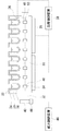
図2に示されるように、反応部12は、サンプル保持部材としての直方体形状のヒートブロック20を有する。ヒートブロック20には、サンプル容器プレート22(容器集合体)が搭載される。サンプル容器プレート22は、複数のサンプル容器24(容器ピース)で構成される。サンプル容器の数は96個(8×12)である。ヒートブロック20は、各サンプル容器24と対応する位置に容器保持穴26(ウェル)を有する。各容器保持穴26に、サンプルが入った各サンプル容器24が挿入され、保持される。この容器24と保持穴26は、底部が同じ角度のくさび形をなしており、容器24が保持穴26に挿入されると両者は良く密着し、温度の伝達効率が良い。
【0051】
ヒートブロック20の下側には、ペルチェ素子28が配置される。ペルチェ素子28は温度調節装置を構成し、ペルチェ素子28によりヒートブロック20が加熱および冷却される。
【0052】
ヒートブロック20の下方には、容器保持穴26の配列方向に沿って円形の細長い磁石収納穴30が設けられている。磁石収納穴30は、容器保持穴26の底とヒートブロック20の下面の間に配置されている。磁石収納穴30には、磁力制御棒である磁石保持具32が挿入される。磁石保持具32は、棒状であり、その断面は半円である。磁石保持具32は、複数の容器保持穴列の各々に設けられており、したがって磁石保持具32の本数は12本である。磁石保持具32には複数の磁石34が保持されている。さらに、図示されないが、磁石保持具32を磁石収納穴30内で回転させる回転装置が設けられている。回転装置は、ラックおよびピニオンで構成される。
【0053】
上記の磁石保持具32、磁石34および回転装置により本実施の形態の磁気分離装置が構成される。
【0054】
図3は、反応部12の断面図である。既に説明したように、ヒートブロック20にサンプル容器プレート22が載っており、ヒートブロック20の下面にはペルチェ素子28が配置されている。ヒートブロック20には、さらに、温度センサ36が設けられている。温度制御装置38は、温度センサ36で検出される温度に基づいてペルチェ素子28を制御し、サンプル温度を調整する。
【0055】
また、磁気分離装置としては、磁石保持具32が、上述のように磁石収納穴30に挿入されており、磁石保持具32には、複数の磁石34が保持されている。磁石保持具32は、鉄などの強磁性体で構成される。そして、磁石保持具32は、両端では円柱であるが、容器保持穴26が設置された範囲では半円柱である。
【0056】
磁石34は、各磁石34が容器保持穴26の下方に位置するように、磁石保持具32上に並んで配置されている。これら複数の磁石34は、隣合う磁石34のN極とS極の向きが逆になるように配列されている。
【0057】
各磁石34は、永久磁石であり、最大100度程度の温度に耐えられるように、高温まで熱可逆性を持つ高耐熱磁石で構成される。本実施の形態では、磁石34は、ネオジウム・ボロン磁石である。
【0058】
磁石34は以下のようにして磁石保持具32に保持されている。すなわち、磁石34は円柱形状を有し、その断面が円形である。この断面に対応する円形の開口40が、磁石保持具32の半円柱部の平坦面に設けられている。磁石34は、その半分が開口40の中に隠れるようにして、開口40に挿入され、固定されている。
【0059】
各磁石34の半分が磁石保持具32に埋め込まれているので、磁石34の2つの磁化方向端部のうち、一方の端部48が露出し、他方の端部50が磁石保持具34に覆われる。前者の端部は開放され、磁力を提供するのに対して、後者の端部は磁石保持具32により遮蔽される。そこで、前者の端部を開放側の磁化方向端部48と呼び、後者の端部を遮蔽側の磁化方向端部50と呼ぶ。
【0060】
磁石保持具32の端部には、ピニオンギア42が取り付けられており、ピニオンギア42はラック44と噛み合っている。ラック44は、磁石保持具32の長手方向と直角方向に、すなわち、磁石保持具32の端部に沿って設けられている。これらラック44およびピニオン42により磁石保持具32の回転装置が構成される。
【0061】
磁力制御装置46は、図示されないモータの回転を制御することで、ラック44の位置を制御する。ラック44が移動すると、磁石保持具32が回転する。こうして、磁力制御装置46は、磁石保持具32の角度を制御し、これにより下記のように磁力のオンオフを制御する。
【0062】
図4は、磁力のオンオフ制御を示している。磁力オン状態では、開放側の磁化方向端部48がサンプルを向くように、すなわち、露出した磁石端部がサンプルを向くように、磁石保持具32の角度が設定される。磁力をオフにするときは、回転装置により磁石保持具32が180度回転される。これにより、遮蔽側の磁化方向端部50がサンプルを向く。この状態では、強磁性体の磁石保持具32が磁石34とサンプルの間に介在し、サンプルへの磁力の作用を妨害する。こうして、磁石保持具32の反転により、磁力のオンオフが制御される。
【0063】
図5は、磁力オンおよび磁力オフにおける磁気の状態を示している。図示のように、磁力オン状態で磁力がサンプルに作用する。
【0064】
上記のように、本実施の形態では、強磁性体の磁石保持具32を用いて磁力オフ時の磁力を遮断しているが、磁気分離装置の性能の観点からは、磁力の遮断能力がより高いことが望まれる。特に、より強力な磁石を使うときは、磁力遮断能力の向上が求められる。
【0065】
例えば、サンプルの溶媒が純水などの電気的に中性な液体で、かつ磁気微粒子の表面が荷電されている場合、粒子同士が反発し合う力が大きいために、粒子が凝集しにくい性質がある。このような場合には、磁石を強力にすることが考えられるが、磁石の強化に伴って、磁力オフ時の磁力遮断能力の向上も求められる。このような要求に応えるため、本実施の形態の磁気分離装置は以下のように構成されている。
【0066】
図6は、磁石保持具32の断面図を示している。既に説明したように、磁石保持具32は半円柱であり、その断面は半円である。磁石保持具32には円形の開口40が設けられ、この開口40に円柱形の磁石34が保持されている。磁石34の遮蔽側の磁化方向端部50が開口40の中に位置し、開放側の磁化方向端部48は露出している。
【0067】
そして、本実施の形態の特徴として、開口40の底に、非磁性体であるスペーサ52が配置されている。すなわち、スペーサ52は、遮蔽側の磁化方向端部50と磁石保持具32の間に配置される。スペーサ52は、磁化方向端部50の外側に磁気的なギャップを提供する。スペーサ52は、紙、樹脂またはアルミニウム等でよい。スペーサ52の厚さは例えば0.1mm以下でよい。
【0068】
本実施の形態では、非磁性体を設けたことにより、遮蔽側の磁化方向の磁束が弱められる。磁束は、磁化方向に向かわず、その結果、開放側の方向へと効率的に向けられると考えられる。これにより、開放方向の磁束密度を変えずに、磁力遮断方向の磁束密度を効果的に減らすことができると考えられる。
【0069】
図7は、紙製のスペーサを用いたときの磁力遮蔽効果の測定結果である。測定は、サンプルに相当する位置に配置されたガウスメータを用いて行われた。図示のように、磁力オン時の値は、スペーサの有無によらずに殆ど同じである。これに対し、磁力オフ時の値は、スペーサの挿入によって半分程度に減っている。
【0070】
以上に説明したように、本実施の形態によれば、磁石を保持した磁石保持具を回転させる構成を採用したので、磁気分離装置を小型化できる。すなわち、磁石とサンプルの距離を変更する構成と比べると、磁石をその場で回転すればよいので、装置の小型化が可能である。
【0071】
このことは、サンプル保持具(図2ではヒートブロック20)の体積を小さくできることを意味し、これにより熱容量が小さくなる。これは、温度を速やかに変えられるので、温度調節にとって有利である。
【0072】
さらに、本実施の形態によれば、遮蔽側の磁化方向端部と磁石保持具の間に非磁性体を配置したので、上述のように、磁力オフ時の磁力遮断能力を向上できる。
【0073】
なお、本実施の形態では、非磁性体はスペーサであったが、本発明はこれに限定されない。非磁性体は空気でもよい。この場合、磁石と磁石保持具の間に隙間(空間)が設けられる。
【0074】
次に、別の実施の形態を説明する。本実施の形態では、遮断強化カバーが設けられる。
【0075】
図8は、本実施の形態における磁気分離装置の断面図である。上述の実施の形態と同様に、半円柱の磁石保持具32が回転可能であり、そして、磁石保持具32に磁石34が保持されている。以下、上述の実施の形態で既に説明した事項の説明は省略する。
【0076】
図8に示されるように、本実施の形態の磁気分離装置は、その特徴として、強磁性体の遮断強化カバー54を有する。図8の下側に示されるように、遮断強化カバー54は、磁力オフ状態にて開放側の磁化方向端部48を覆うように配置され、かつ、この配置にて、開放側の磁化方向端部48両側にて接触部56で磁石保持具32に接するように構成される。磁力オフ状態とは、開放側の磁化方向端部48がサンプルと異なる方向を向いている状態である。要するに、遮断強化カバー54は、磁気分離装置上で磁束を放射する側と反対側に配置される。
【0077】
より詳細には、遮断強化カバー54は略半円筒である。これにより、磁石保持具32の外周面と遮断強化カバー54の内周面が共に円筒面である。両円筒面の径がほぼ等しく設定されているので、両面は、磁石保持具32の回転に伴って摺動する。
【0078】
また、図8の断面において、磁石保持具32は完全な半円であり、その中心角は180度である。一方、遮断強化カバー54の円弧の範囲は、半円より広い。すなわち、中心角が180度より大きい。これにより、磁石保持具32を反転させたときに磁石保持具32と遮断強化カバー54を接触させる接触部56が確保される。
【0079】
本実施の形態によれば、磁力オン時は、遮断強化カバー54と同じ側に磁石保持具32が位置し、磁石保持具32が遮断強化カバー54に収容される。この状態では、上述の実施の形態と同様に磁力が上方のサンプルに提供される。
【0080】
一方、磁力オフ時は、開放側の磁化方向端部48が下方を向き、遮断強化カバー54により覆われる。遮断強化カバー54の両端の接触部56が磁石保持具32に接するので、遮断強化カバー54と磁石保持具32が作る空間に磁化方向端部48が収納される。
【0081】
これにより磁石34は外部と磁気的に遮断され、開放側からの磁束の漏れが防止される。すなわち、図8に示すように、遮断強化カバー54と磁石保持具32により、それらの外周部に沿って磁性体内部で磁気回路が形成され、これにより、外周部より外への漏れ磁束が遮断される。磁石のもつ磁束は外部へ漏洩しない。
【0082】
このようにして、本実施の形態では、磁力オフ時に、開放側の磁化方向端部48の磁力がサンプルに影響するのを効果的に抑制できる。
【0083】
遮断強化カバー54の材質は、強磁性体であればよいが、好ましくは、透磁率が大きく、かつ、飽和磁束密度が大きい材質である。適当な材質は、例えば、純鉄またはパーマロイである。
【0084】
また、図9に示されるように、本実施の形態では、遮断強化カバー54を設けたので、磁気分離装置の構成が、サンプル容器の側面に面するように配置されてもよい。すなわち、磁石保持具32が、隣合うサンプル配列の間に挿入されるように配置されてもよい。
【0085】
この理由を説明すると、遮断強化カバー54を設けない構成では、磁力オフ時に、開放側の磁化方向端部48からの磁力が、隣の列のサンプル容器に作用する。これに対し、遮断強化カバー54を設けると、磁力オフ時にも、開放側の磁化方向端部48からの漏れ磁束がないので、隣の列のサンプル容器への磁力の作用が避けられる。したがって、サンプル容器側面近傍への磁石の配置が可能となる。この例に見られるように、本実施の形態によれば、サンプル周囲の任意の位置への磁石配置が可能となる。
【0086】
以上に説明したように、本実施の形態によれば、遮断強化カバーが、磁力オフ時に、開放側の磁化方向端部を覆い、その両側で磁石保持具に接する。遮断強化カバーと磁石保持具により磁気回路が形成され、その中に開放側の磁化方向端部が配置されるので、磁力を確実に遮蔽できる。
【0087】
また、本実施の形態によれば、磁石保持具の外周面と遮断強化カバーの内周面が共に円筒面であり、磁石保持具の回転に伴って摺動する。磁石保持具の外側に同心の円筒部材を設ければよいので、小型な構成で、遮断強化カバーを備えた装置を実現でき、磁力遮断能力を一層向上できる。
【0088】
また、本実施の形態によれば、遮断強化カバーを設けたので、サンプル容器の底部以外に、サンプル容器の側面等、より広範囲の任意の位置に磁石を配置できる。これにより、例えば、容器側面近傍に磁石を配置でき、したがって、磁気微粒子の固定化による上清分離を、分注機のチップ先端を容器下端付近ぎりぎりまで移動して行わせることが可能になり、分離の精度が向上する。
【0089】
また、本実施の形態によれば、飽和磁束が小さく最高透磁率が大きい材料を遮断強化カバーに使用することで磁力の遮蔽効果をより高めることができる。
【0090】
次に、本発明のもう一つの実施の形態を説明する。本実施の形態では、磁石保持具に遮断強化部材が設けられる。
【0091】
図10は、本実施の形態における磁気分離装置の断面図である。上述の実施の形態と同様に、半円柱の磁石保持具32が回転可能であり、そして、磁石保持具32に磁石34が保持されている。以下、上述の実施の形態で既に説明した事項の説明は省略する。
【0092】
図10に示されるように、本実施の形態の磁気分離装置は、その特徴として、遮断強化部材58が磁石保持具32に設けられている。遮断強化部材58は、強磁性体であって、磁石保持具32を構成する鉄などよりも透磁率が大きい材質で構成される。本実施の形態では、遮断強化部材58はパーマロイからなる。
【0093】
遮断強化部材58は、磁石保持具32の回転の中心から見て遮蔽側の磁化方向端部50の外側に位置するように設けられている。本実施の形態では、遮断強化部材58は磁石保持具32の外面に取り付けられており、これにより、遮断強化部材58は、磁石保持具32を挟んで磁化方向端部50から離れて設けられている。
【0094】
より詳細には、遮断強化部材58は長方形の板で構成される。遮断強化部材58は、複数の磁石34の下方を網羅する大きさおよび形状を有する。そして、磁石保持具32の外面には、平坦部が設けられており、この平坦部に遮断強化部材58が設置されている。
【0095】
本実施の形態によれば、磁力オン時は、上述の実施の形態と同様に、開放側の磁化方向端部48がサンプルに面し、そこからサンプルに磁力が提供される。このとき、磁石保持具32および遮蔽側の磁化方向端部50は、サンプルと反対側に位置している。この部分では、遮断強化部材58が配置されているので、漏れ磁束を捕らえる磁気回路が形成される。したがって、漏れ磁束が効果的に低減される。
【0096】
一方、磁力オフ時、開放側の磁化方向端部48は、サンプルと反対方向を向く。そして、磁石保持具32の外周面がサンプルに面する。磁力オフ時も、磁力オン時と同様、遮断強化部材58が配置されているので、漏れ磁束を捕らえる磁気回路が形成されている。これにより、遮蔽側の磁化方向端部50からサンプルへの磁束が効果的に遮断される。
【0097】
図11は、遮断強化部材を備える構成の変形例を示している。図11の構成では、遮断強化部材60が、磁石34の遮蔽側の磁化方向端部50に直接接するように配置される。ここでも、遮断強化部材60は、パーマロイからなる長方形の板であり、複数の磁石34を網羅するように設けられる。図11の構成によっても、遮断強化部材60が設けられているので、図10の構成と同様に、磁力が効果的に遮断される。
【0098】
図11では、遮断強化部材60が磁石保持具32の内部に設けられている。例えば、磁石保持具32が分割構造を有している。そして、磁石保持具32を構成する部材間に遮断強化部材60が挟まれる。
【0099】
以上に説明したように、本実施の形態によれば、遮蔽側の磁化方向端部からの漏れ磁束が遮断強化部材により捉えられるので、より確実に磁力を遮蔽できる。
【0100】
本実施の形態は、要するに、磁石保持具を複数種類の部材で構成している。そのうち、遮断強化部材は、透磁率の大きい部材からなり、例えばパーマロイからなるが、このような材料は一般に高価である。本実施の形態は、磁石保持具全体ではなく、一部に透磁率の大きい部材を用いている。磁石保持具の材質は、鉄などの安価で加工性のよいものであり、磁石を保持する複雑な形状も容易に作成できる。このようにして、本実施の形態では、磁石保持具の一部を遮断強化部材で構成したので、低いコストで高い磁力遮断能力が得られる。
【0101】
また、図10の構成は、遮断強化部材を磁石から離して、磁石保持具の外面に設けている。本実施の形態は、最大透磁率は大きいが飽和磁束密度が小さい材質を採用できる。そして、このような材質の遮断強化部材の効果的な配置により磁気遮断能力を高めることができる。
【0102】
次に、本発明のもう一つの実施の形態を説明する。本実施の形態は、上述のすべての実施の形態の構成を備え、すなわち、遮蔽側の非磁性体、遮断強化カバーおよび遮断強化部材を備える。
【0103】
図12は、本実施の形態における磁気分離装置の断面図である。上述の実施の形態と同様に、半円柱の磁石保持具32が回転可能であり、そして、磁石保持具32に磁石34が保持されている。
【0104】
遮蔽側の非磁性体、遮断強化カバーおよび遮断強化部材の構成は、上述の各実施の形態で説明した通りである。
【0105】
すなわち、磁石34を埋め込む開口40の底に、非磁性体からなる円板形状のスペーサ52が配置されており、これによりスペーサ52が遮蔽側の磁化方向端部50と磁石保持具32の間に配置される。
【0106】
また、半円筒形状の遮断強化カバー54が、磁力オン時に磁石保持具32を収納するように配置されている。磁力オフ時は、遮断強化カバー54は動かず、磁石保持具32が反転し、開放側の磁化方向端部48が遮断強化カバー54に覆われる。
【0107】
さらに、遮断強化部材58が、磁石保持具32の外面に設けられている。これにより、遮断強化部材58は、遮蔽側の磁化方向端部50を覆っている。
【0108】
本実施の形態は、遮蔽側の非磁性体、遮断強化カバーおよび遮断強化部材の磁力遮断能力を有する。非磁性体により、遮蔽側の磁化方向の磁力が弱められる。遮断強化カバーは、磁力オフ時に、開放側の磁化方向端部からサンプルへの磁力の影響を低減する。さらに、遮断強化部材は、遮蔽側の磁化方向端部からの磁束の漏れを効果的に防止する磁気回路を形成する。このようにして、本実施の形態によれば、磁力遮断能力を一層向上できる。
【0109】
次に、上述の実施の形態の変形例を説明する。上述の実施の形態はハイブリダイゼーション装置であったが、この変形例は、核酸抽出およびハイブリダイゼーションを行う核酸処理装置である。核酸処理装置は複数の反応部を備え、各反応部が上述の構成を備える。複数の反応部の各々は、核酸抽出を行う核酸抽出反応部またはハイブリダイゼーションを行うハイブリダイゼーション反応部である。
【0110】
より詳細な構成例としては、核酸処理装置は、2つの温度制御機能付き磁気分離ユニットを備える。各ユニットは、上記の反応部に相当し、すなわち、反応容器保持具、温度調節装置および磁気分離装置を備える。
【0111】
上記2つのユニットに加えて、チップラック、廃液漕等が備えられる。例えば、5つのチップラック、2つの廃液漕、チップ廃棄ステージ、検出プローブ試薬ステージ、核酸増幅用ステージユニットが設けられる。また、2つの温度制御機能付き磁気分離ユニットが核酸抽出とハイブリダイゼーションに割り当てられており、第1のユニットが核酸抽出を行い、第2のユニットがハイブリダイゼーションを行う。
【0112】
これらのユニット、ラック、ステージ等の構成要素は、テーブル上にマトリックス状に配置される(例えば、横3列、縦4列)。これら構成要素の上を移動できるように、3次元方向に移動可能な分注ヘッドが設けられる。この分注ヘッドが動作して、第1の温度制御機能付き磁気分離ユニットでは核酸抽出が行われ、第2の温度制御機能付き磁気分離ユニットではハイブリダイゼーションが行われる。第1のユニットでは、さらに、核酸増幅、典型的にはPCR、が行われてよい。
【0113】
さらに、分注ヘッドと下方のユニット等の構成の間に介在するように、板状のカバーユニットが設けられてもよい。カバーユニットは、分注ヘッドの下方を覆うように、分注ヘッドより少し大きいサイズを有する。カバーユニットは、分注ヘッドの移動時にヘッド下方に位置し、コンタミを防止する。さらに、カバーユニットの下面にヒータを設け、これにより試薬を適当な温度に保つことも好適である。
【0114】
上記の変形例から明らかなように、本発明は、ハイブリダイゼーション装置に限定されない。本発明は核酸処理装置でよく、核酸処理装置は、典型的には、核酸抽出装置、核酸抽出増幅装置または核酸配列検出装置であり、また、これらの複数の処理を行う装置である。上記の例では、核酸抽出とハイブリダイゼーションが行われる。さらに、本発明の磁気分離装置は、細胞そのものや細胞中の核酸など生体物質の抽出や核酸の塩基配列などの同定を行う任意の装置に適用されてよい。
【0115】
また、以上に説明した実施の形態では、図1に示したように、温度制御と磁気分離を同一箇所で行う技術を取り上げた。この場合、上述したように、本発明が好適に作用する。しかし、本発明はこのような装置に限定されない。例えば、温度制御箇所と磁気分離箇所が分析装置上で離れる場合でも、本発明は適用されてよく、小型化と磁力制御能力の向上といった本発明の利点が得られ、また、分析装置の小型化が可能になる。
【0116】
その他にも、本発明は、上述の実施の形態に限定されず、上述の実施の形態が本発明の範囲内で当業者により変形可能なことはもちろんである。
【0117】
【発明の効果】
以上に説明したように、本発明によれば、磁石を保持した磁石保持具を回転させる構成を採用したので、磁気分離装置を小型化できる。さらに、本発明では、遮蔽側の磁化方向端部と磁石保持具の間に非磁性体を配置したので、磁力オフ時に磁力をより確実に遮断できる。
【0118】
また、本発明によれば、遮断強化カバーが、磁力オフ時に、開放側の磁化方向端部を覆い、その両側で磁石保持具に接する。遮断強化カバーと磁石保持具により磁気回路が形成され、その中に開放側の磁化方向端部が配置されるので、開放側からの磁力の影響を抑えることができ、より確実に磁力を遮断できる。
【0119】
また、本発明によれば、遮蔽側の磁化方向端部からの漏れ磁束が遮断強化部材により捉えられるので、より確実に磁力を遮蔽できる。本発明は、保持具全体ではなく、一部に透磁率の大きい部材を用いるので、高価な材料が少なくてよく、コスト面でも有利である。
【0120】
また、本発明によれば、上述の磁気分離装置の磁石保持具が反応部の反応容器保持具に回転可能に設けられる。磁気分離装置の小型化により、内蔵される磁気分離装置のスペースを縮小できる。スペース縮小に伴い反応容器保持具の熱容量の低減が可能なので、温度調節能力を向上できる。温度調節能力の向上と上記の磁気遮断能力の向上により、反応部での反応の性能を向上できる。
【図面の簡単な説明】
【図1】本実施の形態の磁気分離装置が備えられるハイブリダイゼーション装置を示す図である。
【図2】ハイブリダイゼーション装置の反応部の構成を示す図である。
【図3】ハイブリダイゼーション装置の反応部の断面図であり、磁気分離装置の構成を示す図である。
【図4】磁石保持具の回転による磁力オンオフ制御を示す図である。
【図5】磁力オンおよび磁力オフにおける磁気の状態を示す図である。
【図6】遮蔽側に非磁性体であるスペーサを設けた磁気分離装置の断面図である。
【図7】磁気分離装置の磁力遮断能力を示す図である。
【図8】別の実施の形態における、遮断強化カバーを設けた磁気分離装置の断面図である。
【図9】遮断強化カバーを設けた磁気分離装置の応用例を示す図である。
【図10】別の実施の形態における、遮断強化部材を設けた磁気分離装置の断面図である。
【図11】遮断強化部材を設けた磁気分離装置の変形例の断面図である。
【図12】別の実施の形態における、遮蔽側の非磁性体、遮断強化カバーおよび遮断強化部材を備えた磁気分離装置の断面図である。
【符号の説明】
20 ヒートブロック
22 サンプル容器プレート
24 サンプル容器
26 容器保持穴
28 ペルチェ素子
30 磁石収納穴
32 磁石保持具
34 磁石
42 ラック
44 ピニオン
46 磁力制御装置
48 開放側の磁化方向端部
50 遮蔽側の磁化方向端部
52 スペーサ
54 遮断強化カバー
56 接触部
58 遮断強化部材[0001]
TECHNICAL FIELD OF THE INVENTION
The present invention relates to a magnetic separation device for magnetic fine particles, and more particularly, to a small-sized magnetic separation device having improved magnetic force on / off control capability.
[0002]
[Prior art]
2. Description of the Related Art Conventionally, it has been known to extract biological substances such as nucleic acids in cells and identify the base sequence of nucleic acids using magnetic fine particles. One of such techniques is a hybridization method described below.
[0003]
The nucleic acid hybridization method is used to specifically detect a specific gene. For example, using a nucleic acid probe-immobilized particle as a probe, a target nucleic acid of a liquid sample is hybridized with a nucleic acid probe in a reaction vessel, and then solid / liquid separation (B / F separation) is performed to hybridize on the particle. The amount of the target nucleic acid thus determined is measured. In the hybridization method, magnetic fine particles have attracted attention as particles for immobilizing nucleic acid probes from the viewpoint of simplicity of B / F separation.
[0004]
When using magnetic fine particles, it is necessary to control to turn on / off the magnetic force generated by the magnetic force generation source. Conventionally, current control of an electromagnet is generally performed. Further, the position of the magnet (distance from the sample) is controlled such that the permanent magnet is moved closer to or away from the sample.
[0005]
B / F separation using magnetic fine particles is described, for example, in
[0006]
[Patent Document 1]
Patent No. 3115501
[Patent Document 2]
JP-A-11-156231
[Patent Document 3]
JP-A-8-29425
[0007]
[Problems to be solved by the invention]
The B / F separation device using the magnetic fine particles as described above is referred to as a magnetic separation device in this specification. Conventionally, on a hybridization device, a magnetic separation device is separated from a temperature control portion (a portion where a sample reaction is caused by temperature control such as heating and cooling). On the other hand, if temperature control and magnetic separation are performed in one place, the size of the magnetic separation device needs to be reduced.
[0008]
That is, in the temperature control, it is required that the temperature is rapidly changed by heating and cooling. To this end, it is effective to reduce the heat capacity of the sample holding member, and to reduce the heat capacity, it is effective to reduce the volume of the sample holding member. Then, in order to reduce the volume of the sample holding member, it is required to reduce the size of the magnetic separation device provided in the sample holding member.
[0009]
However, the conventional technology for controlling electromagnets has a lower magnetic flux density volume efficiency than permanent magnets, and is too large to obtain sufficient magnetic force, and is not suitable for miniaturization.
[0010]
In addition, when an electromagnet is used, the controllability of the magnetic force is good, but the coil generates heat when a current flows through the electromagnet. This is disadvantageous in integrating temperature control and magnetic separation into one place.
[0011]
Further, with respect to a technique for controlling the distance between the sample and the permanent magnet, the magnet must be kept away from the sample when the magnetic force is turned off, and a space for the magnet is required, and miniaturization is difficult. The use of stronger magnets requires more space.
[0012]
In addition, it is conceivable to move the sample container away from the magnet, which means that the sample is also moved away from the temperature control device, and there is a high possibility that the temperature of the sample will greatly change.
[0013]
As described above, it is desired to reduce the size of the magnetic separation device. In addition, the magnetic separation device is required to reliably shut off the magnetic force when the magnetic force is turned off.
[0014]
For example, if the solvent of the sample is an electrically neutral liquid such as pure water and the surface of the magnetic fine particles is charged, the particles are less likely to aggregate because the repulsion between the particles is large. is there. In such a case, it is conceivable to employ a strong magnet in order to avoid an increase in the time required for immobilization. However, when the magnet is made strong, the ability to cut off the magnetic force when the magnetic force is turned off is reduced, and the magnetic force may act on the sample. As a result, when the sample is to react while the magnetic force is off, there is a possibility that the leaked magnetic force acts to collect the magnetic fine particles.
[0015]
Therefore, in order to avoid such a problem, even when a strong magnet is used, it is required to sufficiently shut off the magnetic force when the magnetic force is turned off.
[0016]
The present invention has been made in view of the above background, and an object of the present invention is to provide a magnetic separation device which is small in size and has a high magnetic shielding ability.
[0017]
[Means for Solving the Problems]
The magnetic separation device according to the present invention includes at least one magnet serving as a magnetic force source and a ferromagnetic material, and magnetizes the at least one magnet on the shield side so that an end in the open magnetization direction is exposed. The magnet holder includes a magnet holder that is held at the direction end, a rotating unit that rotates the magnet holder, and a non-magnetic body disposed between the magnetized end on the shielding side and the magnet holder.
[0018]
According to the present invention, the configuration in which the magnet holder holding the magnet is rotated is employed, so that the magnetic separation device can be downsized. Further, in the present invention, since the non-magnetic material is arranged between the magnetized end on the shielding side and the magnet holder, the magnetic force can be more reliably cut off when the magnetic force is turned off.
[0019]
The magnet holder is preferably a ferromagnetic material, and is made of, for example, stainless steel such as iron or martensite, to which a magnet can be attracted. Preferably, the plurality of permanent magnets are arranged so as to line up on the rod-shaped holder. The non-magnetic material is made of, for example, paper, resin, or aluminum. The non-magnetic material may be air.
[0020]
Preferably, the magnetic separation device of the present invention is arranged such that, when the magnet holder is rotated by the rotating means and the open-side magnetized direction end faces a different direction from the sample, the open-side magnetized direction end And a shielding enhancement cover made of a magnetic material, which is disposed so as to be in contact with the magnet holder on both sides of the open end in the magnetization direction.
[0021]
According to the present invention, when the magnetic force is turned off, the cut-off reinforcing cover covers the open end in the magnetization direction and contacts the magnet holder on both sides. A magnetic circuit is formed by the shielding enhancement cover and the magnet holder, and the end of the open side in the magnetization direction is arranged therein, so that the influence of the magnetic force from the open side can be suppressed, and the magnetic force can be more reliably shut off. .
[0022]
The barrier enhancement cover is preferably ferromagnetic. More preferably, the shielding enhancement cover is made of a material having a high magnetic permeability and a high saturation magnetic flux density, and is made of, for example, pure iron or permalloy.
[0023]
Preferably, the outer peripheral surface of the magnet holder and the inner peripheral surface of the shielding enhancement cover are both cylindrical surfaces, and slide with the rotation of the magnet holder. With a small configuration, it is possible to realize an apparatus provided with a shielding enhancement cover.
[0024]
Preferably, the magnetic separation device is provided on the magnet holder so as to be located outside an end in the magnetization direction on the shield side when viewed from the center of rotation by the rotating means, and has a higher magnetic permeability than the magnet holder. It has a blocking reinforcement member made of a large material.
[0025]
According to the present invention, the leakage magnetic flux from the end portion in the magnetization direction on the shielding side is captured by the shielding reinforcing member, so that the magnetic force can be more reliably shielded. The blocking reinforcing member is, for example, permalloy. According to the present invention, since a member having high magnetic permeability is used for a part of the holder instead of the entire holder, an expensive material may be reduced and the cost is advantageous.
[0026]
Note that the cutoff reinforcing member may be provided at a distance from the end in the magnetization direction with the magnet holder interposed therebetween. Then, the blocking enhancement member may be attached to the outer surface of the magnet holder. Materials having physical properties that have high maximum magnetic permeability but low saturation magnetic flux density can also be used. Further, the cut-off reinforcing member may be interposed between the magnet direction end on the magnetic force break side and the magnet holder.
[0027]
Another embodiment of the present invention is a hybridization device provided with the magnetic separation device for magnetic fine particles described above. Another embodiment of the present invention is a nucleic acid extracting apparatus provided with the above magnetic fine particle magnetic separation apparatus. Further, a nucleic acid extraction amplification treatment or a nucleic acid amplification treatment may be performed.
[0028]
Further, another embodiment of the present invention is a nucleic acid extraction and hybridization apparatus provided with the magnetic separation apparatus for magnetic fine particles described above. Here, a plurality of magnetic separation devices may be provided in a plurality of reaction units, respectively, and each of the plurality of reaction units may be a nucleic acid extraction reaction unit for performing nucleic acid extraction or a hybridization reaction unit for performing hybridization. The nucleic acid extraction process and the hybridization process can be performed by one device. Further, a nucleic acid extraction amplification treatment or a nucleic acid amplification treatment may be performed.
[0029]
Another aspect of the present invention is a nucleic acid processing apparatus including the magnetic separation device for magnetic fine particles described above, and further including a reaction unit, wherein the reaction unit includes a reaction container holder for holding a reaction container, Temperature adjusting means for adjusting the temperature of the container holder, wherein the magnet holder of the magnetic separation device is rotatably provided on the reaction container holder. The nucleic acid processing device is, for example, a device that performs nucleic acid extraction, nucleic acid amplification, hybridization, or two or more of these processes.
[0030]
In this embodiment, temperature control and magnetic separation are performed at the same location. According to the present invention, the space for the built-in magnetic separator can be reduced by downsizing the magnetic separator. Since the heat capacity of the reaction container holder can be reduced as the space is reduced, the temperature control ability can be improved. The reaction performance in the reaction section can be improved by improving the temperature control capability and the above-described magnetic blocking capability.
[0031]
BEST MODE FOR CARRYING OUT THE INVENTION
FIG. 1 shows a hybridization device provided with the magnetic separation device of the present invention. The
[0032]
The
[0033]
The chip rack /
[0034]
The waste liquid container is located below the chip rack. The waste liquid storage container is used for storing the waste liquid sucked up from the
[0035]
The cleaning
[0036]
The
[0037]
The
[0038]
The nucleic acid hybridization method includes a one-step method and a two-step method (sandwich method). The
[0039]
The
[0040]
(1) A reaction vessel into which the nucleic acid probe-immobilized magnetic particles and the labeled sample nucleic acid are injected and mixed is set in the
[0041]
(2) The temperature in the reaction vessel is changed to the nucleic acid annealing temperature, and the temperature is maintained for a predetermined time to perform annealing.
[0042]
(3) The magnetic separation device operates to immobilize the sample nucleic acid bound to the magnetic particles (magnetic on). In the present embodiment, immobilization is performed at the bottom of the container.
[0043]
(4) The arm unit operates to move to the chip rack /
[0044]
(5) The arm unit moves to the
[0045]
(6) The arm unit moves to the chip rack /
[0046]
(7) The arm unit moves to the cleaning
[0047]
(8) The above cleaning operations (5) to (7) are repeated a predetermined number of times. Finally, the cleaning liquid is injected into the reaction vessel.
[0048]
In the above processing, the magnetic force of the magnetic separation device is turned off in the denature of (1) and the annealing of (2). Then, the magnetic force is turned on in (3). It is also considered preferable to repeatedly turn on and off the magnetic force while the cleaning liquid is being injected.
[0049]
FIG. 2 shows the configuration of the
[0050]
As shown in FIG. 2, the
[0051]
A
[0052]
Below the
[0053]
The
[0054]
FIG. 3 is a sectional view of the
[0055]
Further, as the magnetic separation device, the
[0056]
The
[0057]
Each
[0058]
The
[0059]
Since half of each
[0060]
A
[0061]
The magnetic
[0062]
FIG. 4 shows the on / off control of the magnetic force. In the magnetic force ON state, the angle of the
[0063]
FIG. 5 shows a magnetic state when the magnetic force is on and the magnetic force is off. As shown, the magnetic force acts on the sample when the magnetic force is on.
[0064]
As described above, in the present embodiment, the magnetic force when the magnetic force is turned off is blocked by using the
[0065]
For example, if the solvent of the sample is an electrically neutral liquid such as pure water and the surface of the magnetic fine particles is charged, the particles are less likely to aggregate because the repulsion between the particles is large. is there. In such a case, it is conceivable to increase the strength of the magnet, but with the strengthening of the magnet, it is also required to improve the ability to interrupt the magnetic force when the magnetic force is off. In order to meet such a demand, the magnetic separation device of the present embodiment is configured as follows.
[0066]
FIG. 6 shows a sectional view of the
[0067]
As a feature of the present embodiment, a
[0068]
In the present embodiment, the provision of the non-magnetic material weakens the magnetic flux in the magnetization direction on the shield side. It is believed that the magnetic flux does not go in the direction of magnetization and, as a result, is efficiently directed in the direction of the open side. Thus, it is considered that the magnetic flux density in the magnetic force blocking direction can be effectively reduced without changing the magnetic flux density in the opening direction.
[0069]
FIG. 7 shows a measurement result of a magnetic shielding effect when a paper spacer is used. The measurement was performed using a Gauss meter placed at a position corresponding to the sample. As shown, the values when the magnetic force is on are almost the same regardless of the presence or absence of the spacer. On the other hand, the value when the magnetic force is off is reduced to about half by inserting the spacer.
[0070]
As described above, according to the present embodiment, the configuration in which the magnet holder that holds the magnet is rotated is employed, so that the size of the magnetic separation device can be reduced. That is, as compared with the configuration in which the distance between the magnet and the sample is changed, the magnet can be rotated on the spot, so that the apparatus can be downsized.
[0071]
This means that the volume of the sample holder (the
[0072]
Further, according to the present embodiment, since the non-magnetic material is arranged between the end portion in the magnetization direction on the shield side and the magnet holder, as described above, the ability to interrupt the magnetic force when the magnetic force is off can be improved.
[0073]
In this embodiment, the nonmagnetic material is a spacer, but the present invention is not limited to this. The non-magnetic material may be air. In this case, a gap (space) is provided between the magnet and the magnet holder.
[0074]
Next, another embodiment will be described. In the present embodiment, a shielding enhancement cover is provided.
[0075]
FIG. 8 is a cross-sectional view of the magnetic separation device according to the present embodiment. As in the above-described embodiment, the
[0076]
As shown in FIG. 8, the magnetic separation device of the present embodiment has, as a feature thereof, a shielding
[0077]
More specifically, the
[0078]
In the cross section of FIG. 8, the
[0079]
According to the present embodiment, when the magnetic force is turned on, the
[0080]
On the other hand, when the magnetic force is off, the open side magnetization direction end 48 faces downward and is covered by the cut-off strengthening
[0081]
Thereby, the
[0082]
In this manner, in the present embodiment, when the magnetic force is turned off, it is possible to effectively suppress the magnetic force of the open-side magnetization direction end 48 from affecting the sample.
[0083]
The material of the shielding
[0084]
Further, as shown in FIG. 9, in the present embodiment, since the shielding
[0085]
Explaining the reason, in the configuration in which the shielding
[0086]
As described above, according to the present embodiment, when the magnetic force is turned off, the cut-out reinforcing cover covers the open end in the magnetization direction, and contacts the magnet holder on both sides. Since a magnetic circuit is formed by the shielding enhancement cover and the magnet holder, and the open side magnetization direction end is disposed therein, the magnetic force can be reliably shielded.
[0087]
Further, according to the present embodiment, both the outer peripheral surface of the magnet holder and the inner peripheral surface of the shielding reinforcement cover are cylindrical surfaces, and slide with the rotation of the magnet holder. Since a concentric cylindrical member may be provided outside the magnet holder, it is possible to realize a device having a small-sized configuration and a shielding enhancement cover, and the magnetic force shielding ability can be further improved.
[0088]
Further, according to the present embodiment, since the shielding enhancement cover is provided, the magnet can be arranged at an arbitrary position in a wider range such as the side surface of the sample container other than the bottom of the sample container. Thereby, for example, a magnet can be arranged near the side of the container, so that the supernatant can be separated by immobilizing the magnetic fine particles by moving the tip end of the dispenser to near the bottom of the container, Separation accuracy is improved.
[0089]
Further, according to the present embodiment, the shielding effect of the magnetic force can be further enhanced by using a material having a small saturation magnetic flux and a large maximum magnetic permeability for the shielding enhancement cover.
[0090]
Next, another embodiment of the present invention will be described. In the present embodiment, the magnet holding member is provided with the shielding reinforcing member.
[0091]
FIG. 10 is a cross-sectional view of the magnetic separation device according to the present embodiment. Similarly to the above-described embodiment, the
[0092]
As shown in FIG. 10, the magnetic separation device according to the present embodiment is characterized in that a
[0093]
The
[0094]
More specifically, the
[0095]
According to the present embodiment, when the magnetic force is turned on, similarly to the above-described embodiment, the open-side magnetization direction end 48 faces the sample, from which magnetic force is provided to the sample. At this time, the
[0096]
On the other hand, when the magnetic force is off, the open side magnetization direction end 48 faces in the opposite direction to the sample. Then, the outer peripheral surface of the
[0097]
FIG. 11 shows a modified example of the configuration including the blocking reinforcement member. In the configuration of FIG. 11, the shielding
[0098]
In FIG. 11, the
[0099]
As described above, according to the present embodiment, the magnetic flux leaking from the end portion in the magnetization direction on the shielding side is captured by the shielding reinforcing member, so that the magnetic force can be more reliably shielded.
[0100]
In the present embodiment, in short, the magnet holder is constituted by a plurality of types of members. Among them, the blocking reinforcement member is made of a member having high magnetic permeability, for example, permalloy, but such a material is generally expensive. In the present embodiment, a member having high magnetic permeability is used for a part of the magnet holder, not for the whole magnet holder. The material of the magnet holder is inexpensive and has good workability, such as iron, and a complicated shape for holding the magnet can be easily created. In this manner, in the present embodiment, since a part of the magnet holder is constituted by the shielding reinforcing member, a high magnetic shielding ability can be obtained at low cost.
[0101]
In the configuration of FIG. 10, the cut-off reinforcing member is provided on the outer surface of the magnet holder, away from the magnet. In the present embodiment, a material having a large maximum magnetic permeability but a small saturation magnetic flux density can be adopted. And the magnetic shielding ability can be enhanced by the effective arrangement of the shielding reinforcing member made of such a material.
[0102]
Next, another embodiment of the present invention will be described. This embodiment has the configuration of all the above-described embodiments, that is, includes a nonmagnetic material on the shielding side, a shielding enhancement cover, and a shielding enhancement member.
[0103]
FIG. 12 is a cross-sectional view of the magnetic separation device according to the present embodiment. Similarly to the above-described embodiment, the
[0104]
The configurations of the nonmagnetic material on the shielding side, the shielding enhancement cover, and the shielding enhancement member are as described in each of the above embodiments.
[0105]
That is, a disc-shaped
[0106]
In addition, a semi-cylindrical
[0107]
Further, a blocking
[0108]
In the present embodiment, the non-magnetic material on the shielding side, the shielding enhancement cover, and the shielding enhancement member have the magnetic shielding ability. The non-magnetic material weakens the magnetic force in the direction of magnetization on the shield side. When the magnetic force is turned off, the shielding enhancement cover reduces the influence of the magnetic force on the sample from the open end in the magnetization direction. Further, the shielding enhancement member forms a magnetic circuit that effectively prevents the leakage of the magnetic flux from the shield-side end in the magnetization direction. In this way, according to the present embodiment, the magnetic force blocking ability can be further improved.
[0109]
Next, a modified example of the above-described embodiment will be described. Although the above-described embodiment is a hybridization device, this modified example is a nucleic acid processing device that performs nucleic acid extraction and hybridization. The nucleic acid processing apparatus includes a plurality of reaction units, and each reaction unit has the above-described configuration. Each of the plurality of reaction sections is a nucleic acid extraction reaction section for performing nucleic acid extraction or a hybridization reaction section for performing hybridization.
[0110]
As a more detailed configuration example, the nucleic acid processing device includes two magnetic separation units with a temperature control function. Each unit corresponds to the reaction section described above, that is, includes a reaction vessel holder, a temperature controller, and a magnetic separator.
[0111]
In addition to the above two units, a chip rack, a waste liquid tank and the like are provided. For example, five chip racks, two waste liquid tanks, a chip disposal stage, a detection probe reagent stage, and a nucleic acid amplification stage unit are provided. Two magnetic separation units with temperature control function are assigned to nucleic acid extraction and hybridization, the first unit performs nucleic acid extraction, and the second unit performs hybridization.
[0112]
These components such as units, racks, and stages are arranged in a matrix on a table (for example, three rows horizontally and four rows vertically). A dispensing head that is movable in three dimensions is provided so as to be able to move on these components. The dispensing head operates, and nucleic acid extraction is performed in the first magnetic separation unit with a temperature control function, and hybridization is performed in the second magnetic separation unit with a temperature control function. In the first unit, further, nucleic acid amplification, typically PCR, may be performed.
[0113]
Further, a plate-shaped cover unit may be provided so as to be interposed between the configuration of the dispensing head and the lower unit and the like. The cover unit has a size slightly larger than the dispensing head so as to cover below the dispensing head. The cover unit is located below the dispensing head when the dispensing head moves, and prevents contamination. Further, it is also preferable to provide a heater on the lower surface of the cover unit to maintain the reagent at an appropriate temperature.
[0114]
As is evident from the above modifications, the present invention is not limited to a hybridization device. The present invention may be a nucleic acid processing device, which is typically a nucleic acid extraction device, a nucleic acid extraction / amplification device or a nucleic acid sequence detection device, and a device that performs a plurality of these processes. In the above example, nucleic acid extraction and hybridization are performed. Furthermore, the magnetic separation device of the present invention may be applied to any device that extracts biological substances such as cells themselves or nucleic acids in cells and identifies the base sequence of nucleic acids.
[0115]
Further, in the above-described embodiment, as shown in FIG. 1, a technique in which the temperature control and the magnetic separation are performed in the same place is taken up. In this case, as described above, the present invention works suitably. However, the invention is not limited to such devices. For example, the present invention may be applied even when the temperature control part and the magnetic separation part are separated on the analyzer, and the advantages of the present invention such as miniaturization and improvement of the magnetic force control ability are obtained. Becomes possible.
[0116]
In addition, the present invention is not limited to the above-described embodiment, and it goes without saying that the above-described embodiment can be modified by those skilled in the art within the scope of the present invention.
[0117]
【The invention's effect】
As described above, according to the present invention, the configuration in which the magnet holder that holds the magnet is rotated is adopted, so that the size of the magnetic separation device can be reduced. Further, in the present invention, since the non-magnetic material is arranged between the magnetized end on the shielding side and the magnet holder, the magnetic force can be more reliably cut off when the magnetic force is turned off.
[0118]
Further, according to the present invention, when the magnetic force is turned off, the cut-off strengthening cover covers the open end in the magnetization direction and comes into contact with the magnet holder on both sides. A magnetic circuit is formed by the shielding enhancement cover and the magnet holder, and the end of the open side in the magnetization direction is arranged therein, so that the influence of the magnetic force from the open side can be suppressed, and the magnetic force can be more reliably shut off. .
[0119]
Further, according to the present invention, the leakage magnetic flux from the end portion in the magnetization direction on the shielding side is captured by the shielding reinforcing member, so that the magnetic force can be more reliably shielded. According to the present invention, since a member having high magnetic permeability is used for a part of the holder instead of the entire holder, an expensive material may be reduced and the cost is advantageous.
[0120]
According to the present invention, the magnet holder of the above-described magnetic separation device is rotatably provided on the reaction container holder of the reaction section. By reducing the size of the magnetic separator, the space for the built-in magnetic separator can be reduced. Since the heat capacity of the reaction container holder can be reduced as the space is reduced, the temperature control ability can be improved. The reaction performance in the reaction section can be improved by improving the temperature control capability and the above-described magnetic blocking capability.
[Brief description of the drawings]
FIG. 1 is a diagram showing a hybridization device provided with a magnetic separation device according to an embodiment.
FIG. 2 is a diagram showing a configuration of a reaction unit of the hybridization device.
FIG. 3 is a cross-sectional view of a reaction unit of the hybridization device, showing a configuration of a magnetic separation device.
FIG. 4 is a diagram showing magnetic force on / off control by rotation of a magnet holder.
FIG. 5 is a diagram showing a state of magnetism when a magnetic force is turned on and a magnetic force is turned off.
FIG. 6 is a cross-sectional view of a magnetic separation device provided with a nonmagnetic spacer on a shielding side.
FIG. 7 is a diagram showing a magnetic force blocking ability of the magnetic separation device.
FIG. 8 is a cross-sectional view of a magnetic separator provided with a shielding enhancement cover according to another embodiment.
FIG. 9 is a diagram showing an application example of a magnetic separation device provided with a shielding enhancement cover.
FIG. 10 is a cross-sectional view of a magnetic separation device provided with a blocking reinforcing member according to another embodiment.
FIG. 11 is a cross-sectional view of a modified example of the magnetic separation device provided with the shielding reinforcement member.
FIG. 12 is a cross-sectional view of a magnetic separation device including a nonmagnetic body on a shielding side, a shielding enhancement cover, and a shielding enhancement member according to another embodiment.
[Explanation of symbols]
20 heat blocks
22 Sample container plate
24 sample containers
26 Container holding hole
28 Peltier element
30 magnet storage hole
32 magnet holder
34 magnet
42 racks
44 Pinion
46 Magnetic force control device
48 Open end of magnetization direction
50 End of magnetization direction on shield side
52 Spacer
54 Enhancement cover
56 Contact
58 Blocking reinforcement
Claims (11)
強磁性体で構成され、前記少なくとも一の磁石を、開放側の磁化方向端部が露出するように、遮蔽側の磁化方向端部で保持する磁石保持具と、
前記磁石保持具を回転させる回転手段と、
前記遮蔽側の磁化方向端部と前記磁石保持具の間に配置される非磁性体と、
を有することを特徴とする磁気微粒子の磁気分離装置。At least one magnet that is a magnetic force source;
A magnet holder configured of a ferromagnetic material and holding the at least one magnet at a magnetized end on a shield side such that an open end in a magnetized direction is exposed,
Rotating means for rotating the magnet holder,
A non-magnetic member disposed between the magnetized end of the shield side and the magnet holder;
A magnetic separation device for magnetic fine particles, comprising:
前記磁石保持具が前記回転手段により回転されて、前記開放側の磁化方向端部がサンプルと異なる方向を向くときに、前記開放側の磁化方向端部を覆い、前記開放側の磁化方向端部の両側で前記磁石保持具と接するように配置される、磁性体で構成される遮断強化カバーを有することを特徴とする磁気微粒子の磁気分離装置。The magnetic separation device for magnetic fine particles according to claim 1,
When the magnet holder is rotated by the rotating means and the open-side magnetized direction end faces a different direction from the sample, the magnet-side holder covers the open-side magnetized direction end, and the open-side magnetized direction end is A magnetic separation device for separating magnetic fine particles, comprising: a shielding enhancement cover made of a magnetic material, which is disposed so as to be in contact with the magnet holder on both sides of the magnetic member.
前記回転手段による回転の中心から見て前記遮蔽側の磁化方向端部の外側に位置するように前記磁石保持具に設けられ、前記磁石保持具よりも透磁率の大きい材質からなる遮断強化部材を有することを特徴とする磁気微粒子の磁気分離装置。The magnetic separation device for magnetic fine particles according to claim 1 or 2,
A shielding reinforcing member that is provided on the magnet holder so as to be located outside an end in the magnetization direction on the shield side when viewed from the center of rotation by the rotating means, and is made of a material having a higher magnetic permeability than the magnet holder; A magnetic separation device for magnetic fine particles, comprising:
強磁性体で構成され、前記少なくとも一の磁石を、開放側の磁化方向端部が露出し、遮蔽側の磁化方向端部が覆われるように保持する磁石保持具と、
前記磁石保持具を回転させる回転手段と、
前記磁石保持具が前記回転手段により回転されて、前記開放側の磁化方向端部がサンプルと異なる方向を向くときに、前記開放側の磁化方向端部を覆い、前記開放側の磁化方向端部の両側で前記磁石保持具と接するように配置される、磁性体で構成される遮断強化カバーと、
を有することを特徴とする磁気微粒子の磁気分離装置。At least one magnet that is a magnetic force source;
A magnet holder which is made of a ferromagnetic material and holds the at least one magnet such that an open-side magnetization direction end is exposed and a shield-side magnetization direction end is covered.
Rotating means for rotating the magnet holder,
When the magnet holder is rotated by the rotating means and the open-side magnetized direction end faces a different direction from the sample, the magnet-side holder covers the open-side magnetized direction end, and the open-side magnetized direction end is A shielding enhancement cover made of a magnetic material, which is arranged to be in contact with the magnet holder on both sides of
A magnetic separation device for magnetic fine particles, comprising:
前記磁石保持具の外周面と、前記遮断強化カバーの内周面が共に円筒面であり、前記磁石保持具の回転に伴って摺動することを特徴とする磁気微粒子の磁気分離装置。A magnetic separation device for magnetic fine particles according to claim 4,
An outer peripheral surface of the magnet holder and an inner peripheral surface of the shielding enhancement cover are both cylindrical surfaces, and slide with the rotation of the magnet holder.
強磁性体で構成され、前記少なくとも一の磁石を、開放側の磁化方向端部が露出し、遮蔽側の磁化方向端部が覆われるように保持する磁石保持具と、
前記磁石保持具を回転させる回転手段と、
前記回転手段による回転の中心から見て前記遮蔽側の磁化方向端部の外側に位置するように前記磁石保持具に設けられ、前記磁石保持具よりも透磁率の大きい材質からなる遮断強化部材と、
を有することを特徴とする磁気微粒子の磁気分離装置。At least one magnet that is a magnetic force source;
A magnet holder which is made of a ferromagnetic material and holds the at least one magnet such that an open-side magnetization direction end is exposed and a shield-side magnetization direction end is covered.
Rotating means for rotating the magnet holder,
A shielding reinforcing member provided on the magnet holder so as to be located outside the shield-side magnetization direction end when viewed from the center of rotation by the rotating means, and made of a material having a higher magnetic permeability than the magnet holder; ,
A magnetic separation device for magnetic fine particles, comprising:
前記磁気分離装置の前記磁石保持具が、前記反応容器保持具に回転可能に備えられていることを特徴とする核酸処理装置。The magnetic separation device for magnetic fine particles according to any one of claims 1 to 6, further comprising a reaction unit, wherein the reaction unit has a reaction container holder for holding a reaction container, and a temperature of the reaction container holder. Temperature control means for adjusting the
The nucleic acid processing apparatus, wherein the magnet holder of the magnetic separation device is rotatably provided on the reaction container holder.
Priority Applications (1)
| Application Number | Priority Date | Filing Date | Title |
|---|---|---|---|
| JP2003079257A JP4129864B2 (en) | 2003-03-24 | 2003-03-24 | Magnetic separation device for magnetic particles |
Applications Claiming Priority (1)
| Application Number | Priority Date | Filing Date | Title |
|---|---|---|---|
| JP2003079257A JP4129864B2 (en) | 2003-03-24 | 2003-03-24 | Magnetic separation device for magnetic particles |
Publications (2)
| Publication Number | Publication Date |
|---|---|
| JP2004283728A true JP2004283728A (en) | 2004-10-14 |
| JP4129864B2 JP4129864B2 (en) | 2008-08-06 |
Family
ID=33293424
Family Applications (1)
| Application Number | Title | Priority Date | Filing Date |
|---|---|---|---|
| JP2003079257A Expired - Fee Related JP4129864B2 (en) | 2003-03-24 | 2003-03-24 | Magnetic separation device for magnetic particles |
Country Status (1)
| Country | Link |
|---|---|
| JP (1) | JP4129864B2 (en) |
Cited By (28)
| Publication number | Priority date | Publication date | Assignee | Title |
|---|---|---|---|---|
| JP2009072774A (en) * | 2007-08-31 | 2009-04-09 | Tecan Trading Ag | Microplate carrier having magnets |
| JP2010518400A (en) * | 2007-02-08 | 2010-05-27 | バイオキット,エス.アー. | Magnetic particle cleaning station |
| JP2012147785A (en) * | 2012-02-14 | 2012-08-09 | Tamagawa Seiki Co Ltd | Apparatus for collecting/dispersing magnetic particle in liquid |
| JP2012152734A (en) * | 2012-02-14 | 2012-08-16 | Tamagawa Seiki Co Ltd | Assembly/dispersion apparatus of magnetic particle in liquid |
| JP2012152213A (en) * | 2012-02-14 | 2012-08-16 | Tamagawa Seiki Co Ltd | Device for aggregating/dispersing magnetic particle in liquid |
| JP2013508685A (en) * | 2009-10-16 | 2013-03-07 | プロメガ・コーポレーション | Apparatus for heating, exciting and magnetizing and method of operating the apparatus |
| JP2013544097A (en) * | 2010-11-18 | 2013-12-12 | バイオニア コーポレーション | Automatic purification equipment and automatic purification method for aerosol prevention |
| JP2020528754A (en) * | 2017-08-03 | 2020-10-01 | アジレント・テクノロジーズ・インクAgilent Technologies, Inc. | Sample processing device with integrated heater, shaker and magnet |
| CN111915793A (en) * | 2020-09-01 | 2020-11-10 | 全南群英达电子有限公司 | Point-contact type magnetizing device of magnetic head of cash register and implementation method thereof |
| JP2020535393A (en) * | 2017-09-25 | 2020-12-03 | ホンブレヒティコン システムズ エンジニアリング アクチェンゲゼルシャフト | Devices and methods for immobilizing biomolecules using magnetic particles |
| US10875022B2 (en) | 2007-07-13 | 2020-12-29 | Handylab, Inc. | Integrated apparatus for performing nucleic acid extraction and diagnostic testing on multiple biological samples |
| US10900066B2 (en) | 2006-03-24 | 2021-01-26 | Handylab, Inc. | Microfluidic system for amplifying and detecting polynucleotides in parallel |
| US10913061B2 (en) | 2006-03-24 | 2021-02-09 | Handylab, Inc. | Integrated system for processing microfluidic samples, and method of using the same |
| USD914231S1 (en) | 2019-11-20 | 2021-03-23 | Agilent Technologies, Inc. | Sample processing apparatus |
| JP2021052743A (en) * | 2019-09-25 | 2021-04-08 | 国立大学法人九州大学 | Nucleic acid detection method and nucleic acid detection device |
| USD917063S1 (en) | 2019-11-20 | 2021-04-20 | Agilent Technologies, Inc. | Sample processing apparatus |
| JP2021511206A (en) * | 2018-01-26 | 2021-05-06 | ザ フランシス クリック インスティチュート リミティッド | Test receptacle rack |
| US11060082B2 (en) | 2007-07-13 | 2021-07-13 | Handy Lab, Inc. | Polynucleotide capture materials, and systems using same |
| US11078523B2 (en) | 2003-07-31 | 2021-08-03 | Handylab, Inc. | Processing particle-containing samples |
| US11142785B2 (en) | 2006-03-24 | 2021-10-12 | Handylab, Inc. | Microfluidic system for amplifying and detecting polynucleotides in parallel |
| US11141734B2 (en) | 2006-03-24 | 2021-10-12 | Handylab, Inc. | Fluorescence detector for microfluidic diagnostic system |
| US11266987B2 (en) | 2007-07-13 | 2022-03-08 | Handylab, Inc. | Microfluidic cartridge |
| US11441171B2 (en) | 2004-05-03 | 2022-09-13 | Handylab, Inc. | Method for processing polynucleotide-containing samples |
| US11453906B2 (en) | 2011-11-04 | 2022-09-27 | Handylab, Inc. | Multiplexed diagnostic detection apparatus and methods |
| US11466263B2 (en) | 2007-07-13 | 2022-10-11 | Handylab, Inc. | Diagnostic apparatus to extract nucleic acids including a magnetic assembly and a heater assembly |
| US11549959B2 (en) | 2007-07-13 | 2023-01-10 | Handylab, Inc. | Automated pipetting apparatus having a combined liquid pump and pipette head system |
| US11788127B2 (en) | 2011-04-15 | 2023-10-17 | Becton, Dickinson And Company | Scanning real-time microfluidic thermocycler and methods for synchronized thermocycling and scanning optical detection |
| US11806718B2 (en) | 2006-03-24 | 2023-11-07 | Handylab, Inc. | Fluorescence detector for microfluidic diagnostic system |
Citations (4)
| Publication number | Priority date | Publication date | Assignee | Title |
|---|---|---|---|---|
| JPH0663150U (en) * | 1993-02-15 | 1994-09-06 | 東レ株式会社 | Unreacted component removal device |
| JPH09218201A (en) * | 1995-12-07 | 1997-08-19 | Seiko Instr Inc | Method for separating magnetic particle |
| JPH11500952A (en) * | 1995-02-21 | 1999-01-26 | ダブリュー. シディキー,イクバール | Mixing / separating apparatus and method using magnetic particles |
| JP2001239180A (en) * | 2000-03-01 | 2001-09-04 | Shikoku Kogyo Kk | Apparatus for separating fine sludge contained in grinding liquid |
-
2003
- 2003-03-24 JP JP2003079257A patent/JP4129864B2/en not_active Expired - Fee Related
Patent Citations (4)
| Publication number | Priority date | Publication date | Assignee | Title |
|---|---|---|---|---|
| JPH0663150U (en) * | 1993-02-15 | 1994-09-06 | 東レ株式会社 | Unreacted component removal device |
| JPH11500952A (en) * | 1995-02-21 | 1999-01-26 | ダブリュー. シディキー,イクバール | Mixing / separating apparatus and method using magnetic particles |
| JPH09218201A (en) * | 1995-12-07 | 1997-08-19 | Seiko Instr Inc | Method for separating magnetic particle |
| JP2001239180A (en) * | 2000-03-01 | 2001-09-04 | Shikoku Kogyo Kk | Apparatus for separating fine sludge contained in grinding liquid |
Cited By (40)
| Publication number | Priority date | Publication date | Assignee | Title |
|---|---|---|---|---|
| US11078523B2 (en) | 2003-07-31 | 2021-08-03 | Handylab, Inc. | Processing particle-containing samples |
| US11441171B2 (en) | 2004-05-03 | 2022-09-13 | Handylab, Inc. | Method for processing polynucleotide-containing samples |
| US11141734B2 (en) | 2006-03-24 | 2021-10-12 | Handylab, Inc. | Fluorescence detector for microfluidic diagnostic system |
| US11959126B2 (en) | 2006-03-24 | 2024-04-16 | Handylab, Inc. | Microfluidic system for amplifying and detecting polynucleotides in parallel |
| US11806718B2 (en) | 2006-03-24 | 2023-11-07 | Handylab, Inc. | Fluorescence detector for microfluidic diagnostic system |
| US11666903B2 (en) | 2006-03-24 | 2023-06-06 | Handylab, Inc. | Integrated system for processing microfluidic samples, and method of using same |
| US11085069B2 (en) | 2006-03-24 | 2021-08-10 | Handylab, Inc. | Microfluidic system for amplifying and detecting polynucleotides in parallel |
| US11142785B2 (en) | 2006-03-24 | 2021-10-12 | Handylab, Inc. | Microfluidic system for amplifying and detecting polynucleotides in parallel |
| US10913061B2 (en) | 2006-03-24 | 2021-02-09 | Handylab, Inc. | Integrated system for processing microfluidic samples, and method of using the same |
| US10900066B2 (en) | 2006-03-24 | 2021-01-26 | Handylab, Inc. | Microfluidic system for amplifying and detecting polynucleotides in parallel |
| JP2010518400A (en) * | 2007-02-08 | 2010-05-27 | バイオキット,エス.アー. | Magnetic particle cleaning station |
| JP2012063364A (en) * | 2007-02-08 | 2012-03-29 | Biokit S A | Method of using automatic light emission analysis system |
| US10875022B2 (en) | 2007-07-13 | 2020-12-29 | Handylab, Inc. | Integrated apparatus for performing nucleic acid extraction and diagnostic testing on multiple biological samples |
| US11254927B2 (en) | 2007-07-13 | 2022-02-22 | Handylab, Inc. | Polynucleotide capture materials, and systems using same |
| US11266987B2 (en) | 2007-07-13 | 2022-03-08 | Handylab, Inc. | Microfluidic cartridge |
| US11060082B2 (en) | 2007-07-13 | 2021-07-13 | Handy Lab, Inc. | Polynucleotide capture materials, and systems using same |
| US11466263B2 (en) | 2007-07-13 | 2022-10-11 | Handylab, Inc. | Diagnostic apparatus to extract nucleic acids including a magnetic assembly and a heater assembly |
| US11549959B2 (en) | 2007-07-13 | 2023-01-10 | Handylab, Inc. | Automated pipetting apparatus having a combined liquid pump and pipette head system |
| US11845081B2 (en) | 2007-07-13 | 2023-12-19 | Handylab, Inc. | Integrated apparatus for performing nucleic acid extraction and diagnostic testing on multiple biological samples |
| JP2009072774A (en) * | 2007-08-31 | 2009-04-09 | Tecan Trading Ag | Microplate carrier having magnets |
| US8658042B2 (en) | 2007-08-31 | 2014-02-25 | Tecan Trading Ag | Microplate carrier having magnets |
| US8984968B2 (en) | 2009-10-16 | 2015-03-24 | Promega Corporation | Heating, shaking, and magnetizing apparatus and method of operating the same |
| JP2013508685A (en) * | 2009-10-16 | 2013-03-07 | プロメガ・コーポレーション | Apparatus for heating, exciting and magnetizing and method of operating the apparatus |
| US20140030169A1 (en) * | 2009-10-16 | 2014-01-30 | Promega Corporation | Heating, shaking, and magnetizing apparatus and method of operating the same |
| EP2488303B1 (en) * | 2009-10-16 | 2017-03-15 | Promega Corporation | Heating, shaking, and magnetizing apparatus |
| JP2013544097A (en) * | 2010-11-18 | 2013-12-12 | バイオニア コーポレーション | Automatic purification equipment and automatic purification method for aerosol prevention |
| US11788127B2 (en) | 2011-04-15 | 2023-10-17 | Becton, Dickinson And Company | Scanning real-time microfluidic thermocycler and methods for synchronized thermocycling and scanning optical detection |
| US11453906B2 (en) | 2011-11-04 | 2022-09-27 | Handylab, Inc. | Multiplexed diagnostic detection apparatus and methods |
| JP2012147785A (en) * | 2012-02-14 | 2012-08-09 | Tamagawa Seiki Co Ltd | Apparatus for collecting/dispersing magnetic particle in liquid |
| JP2012152734A (en) * | 2012-02-14 | 2012-08-16 | Tamagawa Seiki Co Ltd | Assembly/dispersion apparatus of magnetic particle in liquid |
| JP2012152213A (en) * | 2012-02-14 | 2012-08-16 | Tamagawa Seiki Co Ltd | Device for aggregating/dispersing magnetic particle in liquid |
| JP2020528754A (en) * | 2017-08-03 | 2020-10-01 | アジレント・テクノロジーズ・インクAgilent Technologies, Inc. | Sample processing device with integrated heater, shaker and magnet |
| JP7417799B2 (en) | 2017-09-25 | 2024-01-19 | キアゲン ゲーエムベーハー | Device and method for immobilizing biomolecules using magnetic particles |
| JP2020535393A (en) * | 2017-09-25 | 2020-12-03 | ホンブレヒティコン システムズ エンジニアリング アクチェンゲゼルシャフト | Devices and methods for immobilizing biomolecules using magnetic particles |
| JP2021511206A (en) * | 2018-01-26 | 2021-05-06 | ザ フランシス クリック インスティチュート リミティッド | Test receptacle rack |
| JP2021052743A (en) * | 2019-09-25 | 2021-04-08 | 国立大学法人九州大学 | Nucleic acid detection method and nucleic acid detection device |
| JP7133867B2 (en) | 2019-09-25 | 2022-09-09 | 国立大学法人九州大学 | NUCLEIC ACID DETECTION METHOD AND NUCLEIC ACID DETECTION DEVICE |
| USD917063S1 (en) | 2019-11-20 | 2021-04-20 | Agilent Technologies, Inc. | Sample processing apparatus |
| USD914231S1 (en) | 2019-11-20 | 2021-03-23 | Agilent Technologies, Inc. | Sample processing apparatus |
| CN111915793A (en) * | 2020-09-01 | 2020-11-10 | 全南群英达电子有限公司 | Point-contact type magnetizing device of magnetic head of cash register and implementation method thereof |
Also Published As
| Publication number | Publication date |
|---|---|
| JP4129864B2 (en) | 2008-08-06 |
Similar Documents
| Publication | Publication Date | Title |
|---|---|---|
| JP4129864B2 (en) | Magnetic separation device for magnetic particles | |
| US7622046B2 (en) | Magnetic transfer method, a device for transferring microparticles and a reactor unit | |
| JP4856831B2 (en) | Apparatus and method for mixing magnetic particles with a fluid | |
| JP4886859B2 (en) | Magnetic particle cleaning station | |
| AU2006210041B2 (en) | Device and method for the elimination of magnetic or magnetizable particles from a liquid | |
| JP2004515333A (en) | System and method for manipulating magnetically responsive particles in a liquid sample and collecting DNA or RNA from the sample | |
| ES2674264T3 (en) | Method and device for microparticle treatment | |
| JP3996416B2 (en) | B / F separation method in nucleic acid hybridization | |
| US9694368B2 (en) | Magnetic reagent, magnetic reagent kit, method for treating magnetic carriers, and treatment device therefor | |
| US20030040129A1 (en) | Binding assays using magnetically immobilized arrays | |
| US7776221B2 (en) | Device and method for separating magnetic or magnetizable particles from a liquid | |
| JP2008167722A (en) | Nucleic acid isolation method by heating on magnetic support | |
| US20100300978A1 (en) | Device, system and method for washing and isolating magnetic particles in a continous fluid flow | |
| JP2007101318A (en) | Analyzer | |
| WO2012035462A1 (en) | Magnetic system for particle attraction in a plurality of chambers | |
| US20150024376A1 (en) | Trap and flow system and process for capture of target analytes | |
| JP7417799B2 (en) | Device and method for immobilizing biomolecules using magnetic particles | |
| JP4633627B2 (en) | Biological component separation device and biological component separation method using the same | |
| WO2005059929A2 (en) | Magnetic rod apparatus and method for manipulating magnetic particles for detecting analytes | |
| EP1748295A1 (en) | System for manipulating magnetic particles | |
| JP2004317363A (en) | Nucleic acid analyzer, and analytical method for nucleic acid using it | |
| US20240094099A1 (en) | Magnetic Particle Air Transfer | |
| FI115294B (en) | Handling macroparticles useful as solid phase to bind e.g. biomolecules involves performing at least two treatment steps in same vessel without moving the particles to another vessel | |
| JP2009273428A (en) | Biological substance-detecting cartridge, and biological substance detector |
Legal Events
| Date | Code | Title | Description |
|---|---|---|---|
| A621 | Written request for application examination |
Free format text: JAPANESE INTERMEDIATE CODE: A621 Effective date: 20040928 |
|
| A131 | Notification of reasons for refusal |
Free format text: JAPANESE INTERMEDIATE CODE: A131 Effective date: 20080122 |
|
| A521 | Written amendment |
Free format text: JAPANESE INTERMEDIATE CODE: A523 Effective date: 20080314 |
|
| TRDD | Decision of grant or rejection written | ||
| A01 | Written decision to grant a patent or to grant a registration (utility model) |
Free format text: JAPANESE INTERMEDIATE CODE: A01 Effective date: 20080430 |
|
| A01 | Written decision to grant a patent or to grant a registration (utility model) |
Free format text: JAPANESE INTERMEDIATE CODE: A01 |
|
| A61 | First payment of annual fees (during grant procedure) |
Free format text: JAPANESE INTERMEDIATE CODE: A61 Effective date: 20080514 |
|
| R150 | Certificate of patent or registration of utility model |
Free format text: JAPANESE INTERMEDIATE CODE: R150 |
|
| FPAY | Renewal fee payment (event date is renewal date of database) |
Free format text: PAYMENT UNTIL: 20110530 Year of fee payment: 3 |
|
| FPAY | Renewal fee payment (event date is renewal date of database) |
Free format text: PAYMENT UNTIL: 20110530 Year of fee payment: 3 |
|
| FPAY | Renewal fee payment (event date is renewal date of database) |
Free format text: PAYMENT UNTIL: 20110530 Year of fee payment: 3 |
|
| FPAY | Renewal fee payment (event date is renewal date of database) |
Free format text: PAYMENT UNTIL: 20110530 Year of fee payment: 3 |
|
| FPAY | Renewal fee payment (event date is renewal date of database) |
Free format text: PAYMENT UNTIL: 20110530 Year of fee payment: 3 |
|
| LAPS | Cancellation because of no payment of annual fees |