JP2004281027A - Optical recording medium and optical information processing device - Google Patents
Optical recording medium and optical information processing device Download PDFInfo
- Publication number
- JP2004281027A JP2004281027A JP2003339564A JP2003339564A JP2004281027A JP 2004281027 A JP2004281027 A JP 2004281027A JP 2003339564 A JP2003339564 A JP 2003339564A JP 2003339564 A JP2003339564 A JP 2003339564A JP 2004281027 A JP2004281027 A JP 2004281027A
- Authority
- JP
- Japan
- Prior art keywords
- recording medium
- optical recording
- pit
- light
- light receiving
- Prior art date
- Legal status (The legal status is an assumption and is not a legal conclusion. Google has not performed a legal analysis and makes no representation as to the accuracy of the status listed.)
- Pending
Links
Images


Classifications
-
- G—PHYSICS
- G11—INFORMATION STORAGE
- G11B—INFORMATION STORAGE BASED ON RELATIVE MOVEMENT BETWEEN RECORD CARRIER AND TRANSDUCER
- G11B7/00—Recording or reproducing by optical means, e.g. recording using a thermal beam of optical radiation by modifying optical properties or the physical structure, reproducing using an optical beam at lower power by sensing optical properties; Record carriers therefor
- G11B7/24—Record carriers characterised by shape, structure or physical properties, or by the selection of the material
- G11B7/2407—Tracks or pits; Shape, structure or physical properties thereof
- G11B7/24085—Pits
- G11B7/24088—Pits for storing more than two values, i.e. multi-valued recording for data or prepits
-
- G—PHYSICS
- G11—INFORMATION STORAGE
- G11B—INFORMATION STORAGE BASED ON RELATIVE MOVEMENT BETWEEN RECORD CARRIER AND TRANSDUCER
- G11B7/00—Recording or reproducing by optical means, e.g. recording using a thermal beam of optical radiation by modifying optical properties or the physical structure, reproducing using an optical beam at lower power by sensing optical properties; Record carriers therefor
- G11B7/007—Arrangement of the information on the record carrier, e.g. form of tracks, actual track shape, e.g. wobbled, or cross-section, e.g. v-shaped; Sequential information structures, e.g. sectoring or header formats within a track
- G11B7/0079—Zoned data area, e.g. having different data structures or formats for the user data within data layer, Zone Constant Linear Velocity [ZCLV], Zone Constant Angular Velocity [ZCAV], carriers with RAM and ROM areas
-
- G—PHYSICS
- G11—INFORMATION STORAGE
- G11B—INFORMATION STORAGE BASED ON RELATIVE MOVEMENT BETWEEN RECORD CARRIER AND TRANSDUCER
- G11B7/00—Recording or reproducing by optical means, e.g. recording using a thermal beam of optical radiation by modifying optical properties or the physical structure, reproducing using an optical beam at lower power by sensing optical properties; Record carriers therefor
- G11B7/08—Disposition or mounting of heads or light sources relatively to record carriers
- G11B7/09—Disposition or mounting of heads or light sources relatively to record carriers with provision for moving the light beam or focus plane for the purpose of maintaining alignment of the light beam relative to the record carrier during transducing operation, e.g. to compensate for surface irregularities of the latter or for track following
- G11B7/0901—Disposition or mounting of heads or light sources relatively to record carriers with provision for moving the light beam or focus plane for the purpose of maintaining alignment of the light beam relative to the record carrier during transducing operation, e.g. to compensate for surface irregularities of the latter or for track following for track following only
- G11B7/0903—Multi-beam tracking systems
-
- G—PHYSICS
- G11—INFORMATION STORAGE
- G11B—INFORMATION STORAGE BASED ON RELATIVE MOVEMENT BETWEEN RECORD CARRIER AND TRANSDUCER
- G11B7/00—Recording or reproducing by optical means, e.g. recording using a thermal beam of optical radiation by modifying optical properties or the physical structure, reproducing using an optical beam at lower power by sensing optical properties; Record carriers therefor
- G11B7/08—Disposition or mounting of heads or light sources relatively to record carriers
- G11B7/09—Disposition or mounting of heads or light sources relatively to record carriers with provision for moving the light beam or focus plane for the purpose of maintaining alignment of the light beam relative to the record carrier during transducing operation, e.g. to compensate for surface irregularities of the latter or for track following
- G11B7/0941—Methods and circuits for servo gain or phase compensation during operation
-
- G—PHYSICS
- G11—INFORMATION STORAGE
- G11B—INFORMATION STORAGE BASED ON RELATIVE MOVEMENT BETWEEN RECORD CARRIER AND TRANSDUCER
- G11B7/00—Recording or reproducing by optical means, e.g. recording using a thermal beam of optical radiation by modifying optical properties or the physical structure, reproducing using an optical beam at lower power by sensing optical properties; Record carriers therefor
- G11B7/24—Record carriers characterised by shape, structure or physical properties, or by the selection of the material
- G11B7/2407—Tracks or pits; Shape, structure or physical properties thereof
- G11B7/24085—Pits
Landscapes
- Engineering & Computer Science (AREA)
- Software Systems (AREA)
- Theoretical Computer Science (AREA)
- Optical Recording Or Reproduction (AREA)
- Optical Record Carriers And Manufacture Thereof (AREA)
- Optical Head (AREA)
Abstract
Description
本発明は、光記録媒体及び光情報処理装置に関する。 The present invention relates to an optical recording medium and an optical information processing device.
近年、映像情報、音声情報、又は、コンピュータ上のデータを保存する手段として、記録容量0.65GBのCD、記録容量4.7GBのDVDなどの光記録媒体が普及しつつある。そして、現在では、さらなる記録密度の向上及び大容量化の要求が強くなっている。 In recent years, optical recording media such as a CD with a recording capacity of 0.65 GB and a DVD with a recording capacity of 4.7 GB have become widespread as means for storing video information, audio information, or data on a computer. At present, demands for further improvement in recording density and increase in capacity are increasing.
このような光記録媒体の記録密度を上げる手段としては、光記録媒体に情報の書込み又は読出しを行う光情報処理装置において、対物レンズの開口数(NA)を大きくすること、或いは、光源の波長を短くすることにより、該対物レンズによって集光されて光記録媒体上に形成されるビームスポットを小径化することが有効である。 Means for increasing the recording density of such an optical recording medium include increasing the numerical aperture (NA) of an objective lens or increasing the wavelength of a light source in an optical information processing apparatus for writing or reading information on or from an optical recording medium. It is effective to reduce the diameter of the beam spot formed on the optical recording medium by being condensed by the objective lens by shortening.
そこで、例えば、「CD系光記録媒体」では、対物レンズの開口数が0.50、光源の波長が780nmとされているのに対して、「CD系光記録媒体」よりも高記録密度化がなされた「DVD系光記録媒体」では、対物レンズの開口数が0.65、光源の波長が660nmとされている。そして、光記録媒体は、上述したように、さらなる記録密度の向上及び大容量化が望まれており、そのためには、対物レンズの開口数を0.65よりもさらに大きく、或いは、光源の波長を660nmよりもさらに短くすることが望まれている。このような大容量の光記録媒体及び光情報処理装置として、青色の波長領域の光源を用いて、大容量確保を満足するシステム提案などがある(例えば、非特許文献1参照)。 Therefore, for example, in the “CD optical recording medium”, the numerical aperture of the objective lens is 0.50 and the wavelength of the light source is 780 nm, but the recording density is higher than that of the “CD optical recording medium”. In the “DVD optical recording medium”, the numerical aperture of the objective lens is 0.65 and the wavelength of the light source is 660 nm. As described above, the optical recording medium is desired to further improve the recording density and increase the capacity. To this end, the numerical aperture of the objective lens is set to be larger than 0.65, or the wavelength of the light source is increased. Is desired to be shorter than 660 nm. As such a large-capacity optical recording medium and optical information processing apparatus, there is a system proposal or the like that satisfies a large capacity using a light source in a blue wavelength region (for example, see Non-Patent Document 1).
しかしながら、対物レンズの開口数をより大きく、或いは光源の波長をより短くすると、光記録媒体の各種変動に伴うマージンが低下する問題がある。例えば、光記録媒体のチルト(傾き)によって発生するコマ収差が大きくなる問題がある。コマ収差が発生すると、光記録媒体の情報記録面上に形成されるスポットが劣化するため、正常な記録再生動作が行えなくなる。光記録媒体のチルトによって発生するコマ収差は、一般的に以下の式で与えられる。 However, when the numerical aperture of the objective lens is made larger or the wavelength of the light source is made shorter, there is a problem that a margin accompanying various fluctuations of the optical recording medium is reduced. For example, there is a problem that coma aberration generated due to a tilt (inclination) of an optical recording medium increases. When coma aberration occurs, the spot formed on the information recording surface of the optical recording medium deteriorates, so that a normal recording and reproducing operation cannot be performed. The coma caused by the tilt of the optical recording medium is generally given by the following equation.
W31=((n2−1)/(2n3))×(d×NA3×θ/λ)
ここで、nは光記録媒体の透明基板の屈折率、dは透明基板の厚み、NAは対物レンズの開口数、λは光源の波長、θは光記録媒体のチルト量を意味する。この式から、短波長、高NAほど収差が大きくなることが判る。同様に、光記録媒体の基板厚みの違いによって発生する球面収差も開口数:NAの4乗、波長:λの−1乗に比例するため、短波長、高NAほど球面収差が大きくなる。
W 31 = ((n 2 −1) / (2n 3 )) × (d × NA 3 × θ / λ)
Here, n is the refractive index of the transparent substrate of the optical recording medium, d is the thickness of the transparent substrate, NA is the numerical aperture of the objective lens, λ is the wavelength of the light source, and θ is the amount of tilt of the optical recording medium. From this equation, it can be seen that the aberration increases as the wavelength becomes shorter and the NA increases. Similarly, the spherical aberration caused by the difference in the substrate thickness of the optical recording medium is also proportional to the numerical aperture: NA to the fourth power and the wavelength: λ to the −1 power, so that the shorter the wavelength and the higher the NA, the larger the spherical aberration.
そこで、別の提案として、光記録媒体上に形成されたピットの信号レベルを2値以上の値に制御する多値記録再生方法が提案されている。即ち、従来の光記録媒体では、読取用レーザ光が光記録媒体上を走査したときのピットの有無による反射光量の変化を用いて信号の読出しが行われるのに対して、特許文献1に示されるようなピット深さとピット幅の組合せによる反射光量の変化から信号の読出しを行う多値記録再生方法や、特許文献2に示されるような、ピット深さとピット幅と、ピットの位置ずれの変化から読出しを行う多値記録再生方法が提案されている。 Therefore, as another proposal, a multi-level recording / reproducing method for controlling the signal level of a pit formed on an optical recording medium to a value of two or more has been proposed. That is, in a conventional optical recording medium, signal reading is performed using a change in the amount of reflected light depending on the presence or absence of a pit when a reading laser beam scans the optical recording medium. A multi-level recording / reproducing method for reading a signal from a change in the amount of reflected light due to a combination of a pit depth and a pit width, and a change in a pit depth, a pit width, and a pit position shift as disclosed in Patent Document 2 A multi-value recording / reproducing method for reading data from a device has been proposed.
また、特許文献3中には、記録マーク占有率方式で多値情報を記録する方式に関して、凹凸形状の位相ピットによる場合には、Rf信号の信号利得が最大となるように位相ピットの光学的溝深さをλ/4にすることが記載されている。
しかしながら、特許文献1,2のように、ピット深さとピット幅による多値データが記録された光記録媒体は生産性が非常に悪くなってしまう。
However, the productivity of an optical recording medium on which multi-valued data is recorded based on a pit depth and a pit width as in
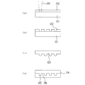
図14及び図15に従来のCD系やDVD系のピットなどの低レベルと高レベルの2値の信号が記録された再生専用光記録媒体の製造工程を示す。製造工程は、周知のように、レーザカッティング(S1)、現像(S2)、スタンパ形成(S3)、レプリケーション(S4)の各工程からなる。即ち、まず、図15(a)に示すように光ビーム100によりガラス基板101のレジスト面102上にピット1となる部分をガラス基板101にあたる深さまで露光して、図15(b)に示すように現像し、この現像した記録原盤に基づき図15(c)に示すようにマスタスタンパ103を作製する。そして、このマスタスタンパ103を用い、既知のリプリケーションプロセスに従って図15(d)に示すように再生専用光記録媒体104を大量製造する。105はグルーブ、106はランドである。
14 and 15 show a conventional process for manufacturing a read-only optical recording medium on which binary signals of low level and high level such as pits of a CD or DVD are recorded. As is well known, the manufacturing process includes laser cutting (S1), development (S2), stamper formation (S3), and replication (S4). That is, first, as shown in FIG. 15A, a portion to be a
以上の従来の製造工程において、ピット深さを制御する場合、ガラス基板101までの露光量をコントロールして、複数の深さのピットを形成する必要がある。しかし、その場合、底が平らでなくなる(丸若しくは面粗さが生じる)。また、露光量の変化に伴う深さの変化が非常に敏感であり、コントロールが難しいなどの問題が経験的に判っている。理論的には、露光量を変えれば深さ変調ができるが、これらの理由に伴い、従来のCD再生用光記録媒体或いはDVD再生用光記録媒体ではガラス基板まで露光を行い、ピットの長さ変調に相当する信号の記録を行うに留まっている。
In the conventional manufacturing process described above, when controlling the pit depth, it is necessary to control the exposure amount up to the
また、本発明が解決しようとする他の課題として、トラックエラー信号の生成方法がある。即ち、CD再生系光記録媒体やDVD再生系光記録媒体に対して採用されてきたトラックエラー信号生成方法は、上述のような短波長化、高NA化、多値記録法などの高密度化或いは高速化には不向きであるとともに、記録系光記録媒体との互換性が困難な方法である。つまり、CD再生系光記録媒体では差動プッシュプル法(以下、DPP法と記す)、DVD再生系光記録媒体では位相差法(以下、DPD法と記す)が適用されている。以下、各々の方法について説明する。 Another problem to be solved by the present invention is a method of generating a track error signal. That is, the track error signal generation method adopted for the CD reproducing system optical recording medium and the DVD reproducing system optical recording medium includes the above-described high-density recording method such as a shorter wavelength, a higher NA, and a multi-value recording method. Alternatively, this method is not suitable for high-speed operation and has difficulty in compatibility with a recording optical recording medium. That is, the differential push-pull method (hereinafter, referred to as DPP method) is applied to a CD reproducing optical recording medium, and the phase difference method (hereinafter, referred to as DPD method) is applied to a DVD reproducing optical recording medium. Hereinafter, each method will be described.
差動プッシュプル法(DPP法)について説明する。CD再生系光記録媒体には、グレーティングを用いて光記録媒体の主トラック上とその隣接トラック上に主光M1と第1及び第2の副光S1,S2とのスポットを形成するDPP(Differential Push-Pull)方式によりトラックエラー信号を生成する方式が採用されている。 The differential push-pull method (DPP method) will be described. In a CD-reproducing optical recording medium, a DPP (Differential) that forms spots of a main light M1 and first and second sub-lights S1 and S2 on a main track and an adjacent track of the optical recording medium using a grating. A method of generating a track error signal by a Push-Pull method is employed.
グレーティングを採用した従来の光ピックアップ(光情報処理装置の光学構成部分)を示した図16を参照すれば、半導体レーザ110から出射されたビームはコリメートレンズ111により平行光束化された後、グレーティング112で回折され、0次及び±1次回折光に分岐される。そして、この分岐された光は対物レンズ113により、図17に示すように光記録媒体114に集光照射される。この時、0次回折光である主光M1のスポットは光記録媒体114の主トラックT上に結ばれ、±1次回折光である第1及び第2の副光S1,S2のスポットは主光M1のスポットに対して先行及び後行し、光記録媒体114のラジアル方向に±1/2トラックピッチほど外れるように結ばれる。
Referring to FIG. 16 showing a conventional optical pickup (an optical component of an optical information processing device) employing a grating, a beam emitted from a semiconductor laser 110 is converted into a parallel light beam by a collimator lens 111, and then a
光記録媒体114から反射されて対物レンズ113を経由した主光M1と第1及び第2副光S1,S2はビームスプリッタ115により照射光と分離され、検出レンズ116を介して受光素子117に受光される。受光素子117は図17に示すように主光M1を受光する第1光検出器118aと、第1及び第2副光S1,S2を各々受光する第2及び第3光検出器118b,118cよりなる。これらの第1ないし第3光検出器118a〜118cは各々独立して光電変換し、光記録媒体114のラジアル方向に分割された2枚の分割板より構成される。
The main light M1 reflected from the
第1ないし第3差動増幅器119,120,121は各々第1ないし第3光検出器118a,118b,118cの検出信号が入力されて第1ないし第3プッシュプル信号を出力する。第1増幅器122は第3プッシュプル信号を所定ゲインG1に増幅し、第2増幅器123は第1増幅器122から出力される信号と第2プッシュプル信号との和信号を所定ゲインG2に増幅する。第4差動器124は第2増幅器123から入力される信号と第1差動器119から入力される主光M1による第1プッシュプル信号とを差動してトラックエラー信号を出力する。この時、第1及び第2増幅器122,123のゲインG1,G2は主光M1と第1及び第2副光S1,S2の強度を考慮して決まる。
The first to third
DPP法は、以上のような再生系の光記録媒体には特に問題ないが、このような構成の光ピックアップ装置で記録系の光記録媒体に対しても動作させる場合、次のような問題が生じる。即ち、光源110から出射された光をグレーティング112により3本の光M1,S1,S2に分岐させて使用するので、
(1)主光M1の光効率が低下して記録用として使用が困難となる。或いは、高速化への適用が困難となる。
(2)また、記録時に第1及び第2副光S1,S2により隣接トラックに記録された信号が消去される。
という問題点がある。
Although the DPP method has no particular problem with the above-described optical recording medium of the reproducing system, the following problem arises when the optical pickup device having such a configuration is operated also on the optical recording medium of the recording system. Occurs. That is, since the light emitted from the light source 110 is branched into three lights M1, S1, and S2 by the
(1) The light efficiency of the main light M1 is reduced, making it difficult to use for recording. Or, it becomes difficult to apply to high speed.
(2) At the time of recording, the signals recorded on the adjacent tracks are erased by the first and second sub-lights S1 and S2.
There is a problem.
次に、位相差法(DPD法)について説明する。DVD再生系光記録媒体ではトラックエラー信号方式として、位相差法或いはDPD(Differential Phase Detection)法と呼ばれる手法が採用されている。この手法は、光記録媒体に照射された光スポットがピット上を通過する際、光スポットのピットの中心からのずれにより受光素子上のピットの写像(回折パターン)が変化することを利用したものであって、受光素子をピットの写像のトラック長さ方向で分割された領域を有するように構成し、各々の領域における受光光量に応じた出力信号レベルを見ると、その変化の仕方は光スポットのピット中心からのずれの方向と量に応じて異なったものとなり、受光素子の出力を所定のレベルで2値化した後に、その2値化した信号の位相を比較し、どちらが先に変化したか、及びレベル変化の時間差(位相差)を見ることで、光スポットのずれの方向と量を示すトラックエラー信号を得ることを可能とするものである。 Next, the phase difference method (DPD method) will be described. In a DVD reproducing optical recording medium, a method called a phase difference method or a DPD (Differential Phase Detection) method is adopted as a track error signal method. This method utilizes the fact that when a light spot irradiated on an optical recording medium passes over a pit, the mapping (diffraction pattern) of the pit on the light receiving element changes due to the deviation of the light spot from the center of the pit. When the light receiving element is configured to have regions divided in the track length direction of the pit mapping, and the output signal level corresponding to the amount of received light in each region is seen, the manner of change is the light spot. After the output of the light receiving element is binarized at a predetermined level, the phases of the binarized signals are compared, and which one has changed first By observing the time difference (phase difference) of the level change, it is possible to obtain a track error signal indicating the direction and amount of displacement of the light spot.
図18ないし図20は、光スポット121が情報ピット132上を通過するときの4分割受光センサ133の受光領域a,b,c,dで受光した反射光量の強度分布パターン(遠視野像)の変化例で、これら各図の(a)は光スポット121と情報ピット132との位置関係を表しており、(b)は光スポット121が情報ピット132上を通過するときの反射光量の遠視野像を各々示している。光スポット121が記録媒体の情報トラック上にある時、その遠視野像は一様の明るさとなる。光スポット121が情報ピット132の中央を通過する場合には、図19に示すように、遠視野像は左右対称のまま変化する。また、図18、図20に示すように、光スポット121が中央からずれて通過する場合には、遠視野像の左右の対称性は崩れ、変化の仕方に時間差(位相差)が生じ、光スポット121が情報ピット132の中心より右側を通るときは、図18(b)に示すように、時計方向に回転するように変化し、反対に、光スポット121が情報ピット132の中心より左側を通るときは、図20(b)に示すように、反時計方向に回転するように変化する。このパターンの変化は、光スポット121が情報ピット132の中心からずれることにより、より鮮明になる。これにより光量を電気信号に変換し、その時間差を検出する処理を行うことによって、図21に示したようなトラックエラー信号を得ることができる。
FIGS. 18 to 20 show intensity distribution patterns (far-field images) of reflected light amounts received in the light receiving areas a, b, c, and d of the four-division
トラックエラー信号は、図18ないし図20のように、反射光量を4分割受光センサ133の受光領域a,b,c,dで受光し、各々の対角に位置する受光領域a,c、b,dの和から、信号の差分を取ればトラックエラー信号は零となり、光スポット121がトラックの真上にあるオントラック状態と呼ばれる状態となる。一方、光スポット121が情報ピットから外れるとその光量に応じ、遠視野像の強度分布の対称性が崩れてトラックエラー信号が生じる。
As shown in FIG. 18 to FIG. 20, the track error signal receives the reflected light amount in the light receiving regions a, b, c, and d of the four-divided
しかしながら、ピットの直径に対してビーム径が大きくなるような大容量光記録媒体においては、1つのビームの中に複数のエッジが存在するような場合は(図6(a)参照)、複数の回折パターンが混在してしまい、DPD法は使用できない。 However, in a large-capacity optical recording medium in which the beam diameter is larger than the pit diameter, when a plurality of edges exist in one beam (see FIG. 6A), a plurality of edges are formed. Diffraction patterns are mixed, and the DPD method cannot be used.
また、DVD再生系では、このようなDPD法が用いられているのに対して、DVD記録系光記録媒体に対しては、前述のDPP法やプッシュプル法が用いられており、記録系と再生系でトラックエラー信号の生成法を切換える必要がある。 In the DVD reproduction system, such a DPD method is used. On the other hand, the DVD recording system optical recording medium uses the DPP method or the push-pull method described above. It is necessary to switch the method of generating the track error signal in the reproducing system.
さらに、特許文献3に示されるような記録マーク占有率方式の場合には、その位相ピットの光学的溝深さがλ/4とされており、プッシュプル信号を殆ど得ることができず、トラックエラー信号検出にプッシュプル法を適用することはできない。
Further, in the case of the recording mark occupation ratio system as disclosed in
本発明の目的は、生産性の容易な多値情報が記録された再生系の光記録媒体を提供するとともに、当該再生系の光記録媒体に関して、記録系の光記録媒体とトラックエラー信号の互換を容易にすることである。 An object of the present invention is to provide an optical recording medium of a reproducing system in which multi-value information with easy productivity is recorded, and to provide an optical recording medium of the reproducing system compatible with a recording optical recording medium and a track error signal. Is to make it easier.
本発明のさらなる目的は、大容量化(小ピット化)された再生系の光記録媒体に対しても簡易なトラックエラー信号生成法を適用可能とすることである。 A further object of the present invention is to make it possible to apply a simple track error signal generation method to an optical recording medium of a reproduction system having a large capacity (small pits).
本発明のさらなる目的は、記録系で問題となるような光量低下、隣接トラックへのクロスイレースのないトラックエラー信号生成法を適用可能とすることである。 A further object of the present invention is to make it possible to apply a method of generating a track error signal without causing a decrease in light amount and causing a cross-erase to an adjacent track, which are problems in a recording system.
請求項1記載の発明は、ピットに照射されたレーザ光の反射光量から再生信号が生成される光記録媒体において、前記ピットが形成される領域が互いに等しい面積のセルに分割され、各々のセルに対するピット占有率に応じて多値の再生信号が生成される面積変調された単一のピットが前記セル毎に形成され、各々の前記ピットの深さHは、照射されるレーザ光の波長をλ、当該媒体基板の屈折率をnとしたとき、
λ/6n<H<λ/4n
を満足する。
According to the present invention, in an optical recording medium in which a reproduction signal is generated from a reflected light amount of a laser beam applied to a pit, a region where the pit is formed is divided into cells having an equal area to each other. A single area-modulated pit in which a multi-valued reproduction signal is generated in accordance with the pit occupation ratio is formed for each of the cells, and the depth H of each of the pits determines the wavelength of the laser light to be irradiated. λ, where n is the refractive index of the medium substrate,
λ / 6n <H <λ / 4n
To be satisfied.
従って、ピットが形成される領域が互いに等しい面積のセルに分割され、各々のセルに対するピット占有率に応じて多値の再生信号が生成される面積変調された1つのピットがセル毎に形成されていることにより、深さ変調により多値情報が記録されているわけでなく、面積変調により多値情報が記録されていることとなるので、ガラス基板まで露光を行う安定した現像工程を確保でき、生産性容易な多値情報が記録された再生系の光記録媒体を提供できる。この際、ピット深さとしては、プッシュプル信号振幅が最大となるλ/6nから、各ピットサイズにおける再生信号の振幅分離が最大、即ち、再生信号のS/Nが最大となるλ/4nの範囲内に設定することにより、ピットが形成された再生系の光記録媒体に対しても、記録系の光記録媒体で一般的に用いられているプッシュプル法によりトラックエラー信号を検出することが可能となる。特に、プッシュプル信号、再生信号が十分に取れるλ/5n付近に設定することが望ましい。即ち、ピット占有率により再生情報がセル単位で記録されている場合、結果的には、ピットの連続的に並んだ構成が、ビームスポットにおいては連続的な溝が形成されたものと同等に観測されるためであり、記録系の光記録媒体のトラックエラー信号の生成との互換性が取れる。 Therefore, the area where the pits are formed is divided into cells having the same area, and one area-modulated pit for generating a multi-valued reproduction signal according to the occupancy of each cell is formed for each cell. By doing so, multi-valued information is not recorded by depth modulation, but multi-valued information is recorded by area modulation, so that a stable developing process of exposing to the glass substrate can be secured. In addition, it is possible to provide a reproduction-type optical recording medium on which multi-value information with easy productivity is recorded. At this time, the pit depth is from λ / 6n at which the push-pull signal amplitude is maximum to λ / 4n at which the amplitude separation of the reproduction signal at each pit size is maximum, that is, λ / 4n at which the S / N of the reproduction signal is maximum. By setting the value within the range, the track error signal can be detected by the push-pull method generally used in the optical recording medium of the recording system even for the reproducing optical recording medium in which pits are formed. It becomes possible. In particular, it is desirable to set around λ / 5n where a push-pull signal and a reproduction signal can be sufficiently obtained. In other words, when the reproduction information is recorded in units of cells according to the pit occupation ratio, as a result, the configuration in which the pits are continuously arranged is observed in the same manner as the beam spot where continuous grooves are formed. This is compatible with the generation of the track error signal of the optical recording medium of the recording system.
請求項2記載の発明は、請求項1記載の光記録媒体において、各々の前記ピットは、各々の前記セルの中心位置に面積変調に応じて異ならせた半径の略円形パターンで形成されている。 According to a second aspect of the present invention, in the optical recording medium according to the first aspect, each of the pits is formed in a substantially circular pattern having a different radius at a center position of each of the cells according to area modulation. .
従って、生産工程において、レーザ露光により容易にピットを形成することができる。実際には光記録媒体は回転されながら露光される点と、露光ビームの強度分布が楕円分布を有するため、回転方向若しくは半径方向に、0%から10%程度の楕円形状となる場合もある。 Therefore, in the production process, pits can be easily formed by laser exposure. Actually, since the optical recording medium is exposed while being rotated and the intensity distribution of the exposure beam has an elliptical distribution, the elliptical shape may be about 0% to 10% in the rotation direction or the radial direction.
請求項3記載の発明は、請求項1又は2記載の光記録媒体において、各々の前記セルに対するピット占有率に応じてN値なる多値の再生信号が生成されるものであり、前記ピットは、面積変調に応じて(N−1)種類の異なるピット径を有し、これらの(N−1)種類のピット径は最大ピット径のピットによる場合のセルからの反射光量とピットなしの場合のセルからの反射光量との間をほぼN等分するように設定されている。 According to a third aspect of the present invention, in the optical recording medium according to the first or second aspect, a multi-valued reproduction signal having N values is generated according to a pit occupancy of each of the cells. And (N-1) types of different pit diameters depending on the area modulation. These (N-1) types of pit diameters are the amount of reflected light from the cell when the pit has the maximum pit diameter and when there is no pit. Is set so as to be approximately equal to N with respect to the amount of light reflected from the cell.
従って、任意のピット深さにおいてもピットの大きさ、即ち、ピット径を変化させることにより、複数の再生信号が得られるものであり、ピット径を変化させることにより多値データの再生が可能であることから、(N−1)種類のピット径として、最大ピット径のピットによる場合のセルからの反射光量とピットなしの場合のセルからの反射光量との間をほぼN等分するように設定することで、N値の多値記録が可能となる。 Therefore, a plurality of reproduction signals can be obtained by changing the pit size, that is, the pit diameter, even at an arbitrary pit depth. By changing the pit diameter, multi-valued data can be reproduced. Therefore, as the (N-1) types of pit diameters, the amount of reflected light from the cell in the case of the pit having the largest pit diameter and the amount of reflected light from the cell in the absence of the pit are almost equally divided into N. By setting, multi-value recording of N values becomes possible.
請求項4記載の発明は、請求項3記載の光記録媒体において、モジュレーションが、60%以上である。ここで、「モジュレーション」とは、最大ピット径での信号レベルと最小ピット径での信号レベルの比で定義される値である。 According to a fourth aspect of the present invention, in the optical recording medium of the third aspect, the modulation is 60% or more. Here, “modulation” is a value defined by the ratio of the signal level at the maximum pit diameter to the signal level at the minimum pit diameter.
従って、製造時などの検査工程においては、モジュレーション60%以上となるように管理してやればよい。このようにすることで、信頼性の高い多値信号のレベル判定が可能となる。 Therefore, in an inspection process such as a manufacturing process, the modulation may be controlled so as to be 60% or more. This makes it possible to determine the level of the multi-level signal with high reliability.
請求項5記載の発明の光情報処理装置は、請求項1ないし4の何れか一記載の光記録媒体に形成されたピットにレーザ光を集光照射する照射光学系と、前記光記録媒体からの反射光を受光する受光光学系と、この受光光学系が受光した検出信号に基づき信号処理を行う信号処理部と、を有し、前記受光光学系は、遠視野における前記ピットからの反射0次光と反射±1次回折光とが重なる領域内で前記光記録媒体のラジアル方向に対して対称に配置された少なくとも一対の第1の受光部を有し、前記信号処理部は、前記第1の受光部の検出信号の差に基づきトラックエラー信号をプッシュプル法により検出する。 According to a fifth aspect of the present invention, there is provided an optical information processing apparatus comprising: an irradiation optical system for converging and irradiating a pit formed on the optical recording medium according to any one of the first to fourth aspects with laser light; A light receiving optical system that receives the reflected light of the pit, and a signal processing unit that performs signal processing based on the detection signal received by the light receiving optical system. At least one pair of first light receiving units symmetrically arranged in the radial direction of the optical recording medium in a region where the next light and the reflected ± 1st-order diffracted light overlap, and the signal processing unit includes the first light receiving unit; The track error signal is detected by the push-pull method based on the difference between the detection signals of the light receiving sections.
従って、請求項1ないし4の何れか一記載の光記録媒体を対象としているので、ピットが形成されたこのような再生系の光記録媒体に対しても、記録系の光記録媒体で一般的に用いられているプッシュプル法によりトラックエラー信号を検出することが可能となる。即ち、ピット占有率により再生情報がセル単位で記録されている場合、結果的には、ピットの連続的に並んだ構成が、ビームスポットにおいては連続的な溝が形成されたものと同等に観測されるためであり、記録系の光記録媒体のトラックエラー信号の生成との互換性が取れる。この場合、ビームスポットの走行方向のピット間のエッジを観測しなくて済むため、DPD法の課題が解決されるとともに、1ビームトラッキングであるため、光効率やクロスイレースなどの問題も解消される。 Therefore, since the present invention is directed to the optical recording medium according to any one of the first to fourth aspects, the recording type optical recording medium is generally used for such a reproduction type optical recording medium in which pits are formed. It is possible to detect a track error signal by the push-pull method used in the above. In other words, when the reproduction information is recorded in units of cells according to the pit occupation ratio, as a result, the configuration in which the pits are continuously arranged is observed in the same manner as the beam spot where continuous grooves are formed. This is compatible with the generation of the track error signal of the optical recording medium of the recording system. In this case, it is not necessary to observe the edge between the pits in the traveling direction of the beam spot, so that the problem of the DPD method is solved. In addition, since one-beam tracking is used, problems such as light efficiency and cross-erase are also solved. .
請求項6記載の発明は、請求項5記載の光情報処理装置において、前記受光光学系は、前記第1の受光部に加えて、遠視野における前記ピットからの反射0次光のみの領域内で前記光記録媒体のラジアル方向に対して対称に配置された少なくとも一対の第2の受光部を有し、前記信号処理部は、トラックエラー信号として前記第1の受光部の検出信号の差を前記第2の受光部の検出信号の差により補正する補正手段を備える。 According to a sixth aspect of the present invention, in the optical information processing apparatus according to the fifth aspect, the light receiving optical system is provided in a region where only the 0th-order light reflected from the pit in a far field is added to the first light receiving unit. And at least a pair of second light receiving units symmetrically arranged in the radial direction of the optical recording medium, wherein the signal processing unit calculates a difference between detection signals of the first light receiving units as a track error signal. The image processing apparatus further includes a correction unit configured to perform correction based on a difference between the detection signals of the second light receiving unit.
従って、単純なプッシュプル法による場合、対物レンズの光軸が固定光学系の光軸からずれたり(シフト)、或いは傾いた(チルト)ときに受光部面上での光量分布が偏るためにトラックエラー信号にオフセットが生じる課題があるが、遠視野における該ピットからの反射0次光と反射±1次回折光とで形成される一対の干渉領域の他に、反射0次光のみの領域内でラジアル方向に対して対称配置された一対の第2の受光部による差の信号を利用して補正することにより、1ビームトラッキングにおいてもオフセットの生じないトラックエラー信号の生成が可能となる。 Therefore, in the case of the simple push-pull method, when the optical axis of the objective lens is shifted (shifted) or tilted (tilted) from the optical axis of the fixed optical system, the light amount distribution on the light receiving unit surface is biased, so that the track is There is a problem that an offset occurs in the error signal. By performing correction using the difference signal between the pair of second light receiving units symmetrically arranged in the radial direction, it is possible to generate a track error signal free from offset even in one-beam tracking.
具体的には、請求項7記載の発明のように、第1の受光部A,Bの検出信号をa,b、第2の受光部C,Dの検出信号をc,dとしたとき、所定のゲインをKを調整して、トラックエラー信号TEを、TE=[(a−b)+K(c−d)]/[(a+b)+K(c+d)]として算出すればよい。
Specifically, when the detection signals of the first light receiving portions A and B are a and b and the detection signals of the second light receiving portions C and D are c and d, as in the invention of
請求項8記載の発明は、請求項7記載の光情報処理装置において、前記補正手段は、トラックエラー信号TEに含まれるオフセット成分が最小となるように所定のゲインKを調整する。 According to an eighth aspect of the present invention, in the optical information processing apparatus of the seventh aspect, the correction means adjusts the predetermined gain K such that an offset component included in the track error signal TE is minimized.
従って、トラックエラー信号TEに含まれるオフセット成分が最小となるように所定のゲインKを調整することにより、オフセットの影響を受けないトラックエラー信号の生成が可能となる。 Therefore, by adjusting the predetermined gain K so that the offset component included in the track error signal TE is minimized, it is possible to generate a track error signal that is not affected by the offset.
請求項9記載の発明は、請求項7又は8記載の光情報処理装置において、請求項1ないし4の何れか一記載の再生系の光記録媒体に加えて、連続的な案内溝が形成された記録系の光記録媒体を適用対象とし、前記補正手段は、再生系の光記録媒体と記録系の光記録媒体とに応じて所定のゲインKを切換え調整する。 According to a ninth aspect of the present invention, in the optical information processing apparatus of the seventh or eighth aspect, in addition to the optical recording medium of the reproducing system according to any one of the first to fourth aspects, a continuous guide groove is formed. The correction means switches and adjusts a predetermined gain K according to the optical recording medium of the reproducing system and the optical recording medium of the recording system.
従って、再生系の光記録媒体と記録系の光記録媒体とに共用する場合も、各々の光記録媒体の特性に適したトラックエラー信号の生成が可能となる。 Therefore, even when the optical recording medium is used for both the reproducing optical recording medium and the recording optical recording medium, a track error signal suitable for the characteristics of each optical recording medium can be generated.
請求項10記載の発明は、請求項7又は8記載の光情報処理装置において、前記光記録媒体が、ピットが形成されたROM領域に加えて、連続的な案内溝が形成されたRAM領域を有するハイブリッド型の光記録媒体の場合には、前記補正手段は、ROM領域とRAM領域とに応じて所定のゲインKを切換え調整する。 According to a tenth aspect of the present invention, in the optical information processing apparatus according to the seventh or eighth aspect, the optical recording medium includes a RAM area having a continuous guide groove in addition to a ROM area having a pit. In the case of a hybrid type optical recording medium having the same, the correction means switches and adjusts a predetermined gain K according to the ROM area and the RAM area.
従って、ピットが形成されたROM領域に加えて、連続的な案内溝が形成されたRAM領域を有するハイブリッド型の光記録媒体に使用する場合も、各々の領域の特性に適したトラックエラー信号の生成が可能となる。 Therefore, even when used for a hybrid optical recording medium having a RAM area in which continuous guide grooves are formed in addition to a ROM area in which pits are formed, a track error signal suitable for the characteristics of each area can be obtained. Generation is possible.
請求項11記載の発明は、請求項6ないし10の何れか一記載の光情報処理装置において、前記第1,第2の受光部は、ラジアル方向に対して4分割された分割構造の受光素子よりなる。 According to an eleventh aspect of the present invention, in the optical information processing device according to any one of the sixth to tenth aspects, the first and second light receiving units have a divided structure divided into four in a radial direction. Consisting of
従って、一般的な並列4分割構造の受光素子を用いることにより、請求項6ないし10記載の発明を容易に実現できる。
Therefore, the invention according to
請求項12記載の発明は、請求項6ないし10の何れか一記載の光情報処理装置において、前記第1,第2の受光部は、前記光記録媒体のラジアル方向に対して対称配置されて遠視野における反射光を所定の方向に回折偏向させる分割構造の回折素子とこの回折素子により回折偏向された光を受光する複数の受光素子との組合せよりなる。 According to a twelfth aspect of the present invention, in the optical information processing device according to any one of the sixth to tenth aspects, the first and second light receiving units are symmetrically arranged with respect to a radial direction of the optical recording medium. It consists of a combination of a diffraction element having a divided structure for diffracting and deflecting reflected light in a far field in a predetermined direction, and a plurality of light receiving elements for receiving light diffracted and deflected by the diffraction element.
従って、受光素子の前段に分割構造の回折素子を介在させることにより、遠視野における反射光を受光素子に向けて回折偏向させることで、受光素子の構成・配置の自由度が増す。 Therefore, by interposing a diffractive element having a divided structure in front of the light receiving element to diffract and deflect reflected light in a far field toward the light receiving element, the degree of freedom in the configuration and arrangement of the light receiving element is increased.
請求項1記載の発明によれば、ピットが形成される領域が互いに等しい面積のセルに分割され、各々のセルに対するピット占有率に応じて多値の再生信号が生成される面積変調された1つのピットがセル毎に形成されていることにより、深さ変調により多値情報が記録されているわけでなく、面積変調により多値情報が記録されていることとなるので、ガラス基板まで露光を行う安定した現像工程を確保でき、生産性容易な多値情報が記録された再生系の光記録媒体を提供することができ、この際、ピット深さとしては、プッシュプル信号振幅が最大となるλ/6nから、各ピットサイズにおける再生信号の振幅分離が最大、即ち、再生信号のS/Nが最大となるλ/4nの範囲内、特にその中間値に設定するようにしたので、ピットが形成された再生系の光記録媒体に対しても、記録系の光記録媒体で一般的に用いられているプッシュプル法によりトラックエラー信号を検出することができ、記録系の光記録媒体のトラックエラー信号の生成との互換性を取ることができる。 According to the first aspect of the present invention, the area in which the pits are formed is divided into cells having the same area, and an area-modulated 1 that generates a multivalued reproduction signal in accordance with the pit occupancy of each cell. Since one pit is formed for each cell, multi-level information is not recorded by depth modulation, but multi-level information is recorded by area modulation. A stable development process to be performed can be ensured, and a reproduction type optical recording medium on which multi-value information can be easily recorded can be provided. At this time, as the pit depth, the push-pull signal amplitude is maximized. From λ / 6n, the amplitude separation of the reproduction signal at each pit size is set to the maximum, that is, within the range of λ / 4n at which the S / N of the reproduction signal is maximum, and particularly to an intermediate value thereof. Formed The track error signal can be detected by the push-pull method generally used for the optical recording medium of the recording system even for the read optical recording medium of the recording system. Compatibility with signal generation can be achieved.
請求項2記載の発明によれば、請求項1記載の光記録媒体において、各々のセルの中心位置に面積変調に応じて異ならせた半径の略円形パターンとすることで、生産工程において、レーザ露光により容易にピットを形成することができる。 According to the second aspect of the present invention, in the optical recording medium according to the first aspect, the center position of each cell is formed into a substantially circular pattern having a radius different according to the area modulation, so that the laser can be produced in the production process. Pits can be easily formed by exposure.
請求項3記載の発明によれば、請求項1又は2記載の光記録媒体において、任意のピット深さにおいてもピットの大きさ、即ち、ピット径を変化させることにより、複数の再生信号が得られるものであり、ピット径を変化させることにより多値データの再生が可能であることから、(N−1)種類のピット径として、最大ピット径のピットによる場合のセルからの反射光量とピットなしの場合のセルからの反射光量との間をほぼN等分するように設定するようにしたので、N値の多値記録が可能となる。 According to the third aspect of the present invention, in the optical recording medium according to the first or second aspect, a plurality of reproduction signals can be obtained by changing a pit size, that is, a pit diameter even at an arbitrary pit depth. Since it is possible to reproduce multi-value data by changing the pit diameter, the amount of reflected light from the cell and the pits when the pits having the maximum pit diameter are used as (N-1) types of pit diameters Since the setting is made so that the amount of light reflected from the cell in the case of no value is substantially equally divided by N, multi-value recording of N values is possible.
請求項4記載の発明によれば、請求項3記載の光記録媒体において、製造時などの検査工程においては、モジュレーション60%以上となるように管理することにより、信頼性の高い多値信号のレベル判定が可能となる。 According to the fourth aspect of the present invention, in the optical recording medium according to the third aspect, in the inspection process such as at the time of manufacturing, the modulation is controlled so as to be 60% or more, so that a highly reliable multi-level signal can be obtained. The level can be determined.
請求項5記載の発明の光情報処理装置によれば、請求項1ないし4の何れか一記載の光記録媒体を対象としているので、ピットが形成されたこのような再生系の光記録媒体に対しても、記録系の光記録媒体で一般的に用いられているプッシュプル法によりトラックエラー信号を検出することができ、記録系の光記録媒体のトラックエラー信号の生成との互換性が取れる上に、ビームスポットの走行方向のピット間のエッジを観測しなくて済むため、DPD法の課題が解決されるとともに、1ビームトラッキングであるため、光効率やクロスイレースなどの問題も解消することができる。
According to the optical information processing apparatus of the invention described in
請求項6及び7記載の発明によれば、請求項5記載の光情報処理装置において、単純なプッシュプル法による場合、対物レンズの光軸が固定光学系の光軸からずれたり(シフト)、或いは傾いた(チルト)ときに受光部面上での光量分布が偏るためにトラックエラー信号にオフセットが生じる課題があるが、遠視野における該ピットからの反射0次光と反射±1次回折光とで形成される一対の干渉領域の他に、反射0次光のみの領域内でラジアル方向に対して対称配置された一対の第2の受光部による差の信号を利用して補正するようにしたので、1ビームトラッキングにおいてもオフセットの生じないトラックエラー信号を生成することができる。 According to the sixth and seventh aspects of the present invention, in the optical information processing apparatus according to the fifth aspect, when the simple push-pull method is used, the optical axis of the objective lens is shifted (shifted) from the optical axis of the fixed optical system. Alternatively, there is a problem that an offset occurs in the track error signal because the light amount distribution on the light receiving unit surface is deviated when tilted (tilt). In addition to the pair of interference regions formed by the above, correction is performed using a difference signal between a pair of second light receiving portions symmetrically arranged in the radial direction in a region of only the reflected zero-order light. Therefore, a track error signal free from offset can be generated even in one-beam tracking.
請求項8記載の発明によれば、請求項7記載の光情報処理装置において、トラックエラー信号TEに含まれるオフセット成分が最小となるように所定のゲインKを調整するようにしたので、オフセットの影響を受けないトラックエラー信号を生成することができる。 According to the eighth aspect of the present invention, in the optical information processing apparatus according to the seventh aspect, the predetermined gain K is adjusted so that the offset component included in the track error signal TE is minimized. A track error signal that is not affected can be generated.
請求項9記載の発明によれば、請求項7又は8記載の光情報処理装置において、再生系の光記録媒体と記録系の光記録媒体とに応じて所定のゲインKを切換え調整するようにしたので、再生系の光記録媒体と記録系の光記録媒体とに共用する場合も、各々の光記録媒体の特性に適したトラックエラー信号を生成することができる。 According to the ninth aspect of the present invention, in the optical information processing apparatus according to the seventh or eighth aspect, the predetermined gain K is switched and adjusted according to the reproduction type optical recording medium and the recording type optical recording medium. Therefore, even when the optical recording medium is used for both the reproducing optical recording medium and the recording optical recording medium, a track error signal suitable for the characteristics of each optical recording medium can be generated.
請求項10記載の発明によれば、請求項7又は8記載の光情報処理装置において、前記光記録媒体がハイブリッド型の光記録媒体の場合には、ROM領域とRAM領域とに応じて所定のゲインKを切換え調整するようにしたので、ハイブリッド型の光記録媒体に使用する場合も、各々の領域の特性に適したトラックエラー信号を生成することができる。 According to the tenth aspect of the present invention, in the optical information processing apparatus according to the seventh or eighth aspect, when the optical recording medium is a hybrid type optical recording medium, a predetermined value is determined according to a ROM area and a RAM area. Since the gain K is switched and adjusted, a track error signal suitable for the characteristics of each area can be generated even when used for a hybrid optical recording medium.
請求項11記載の発明によれば、一般的な並列4分割構造の受光素子を用いることにより、請求項6ないし10記載の発明を容易に実現することができる。 According to the eleventh aspect of the present invention, the inventions of the sixth to tenth aspects can be easily realized by using a light receiving element having a general parallel four-division structure.
請求項12記載の発明によれば、請求項6ないし10の何れか一記載の光情報処理装置において、受光素子の前段に分割構造の回折素子を介在させ、遠視野における反射光を受光素子に向けて回折偏向させるようにしたので、受光素子の構成・配置の自由度を向上させることができる。 According to the twelfth aspect of the present invention, in the optical information processing apparatus according to any one of the sixth to tenth aspects, a diffraction element having a divided structure is interposed in front of the light receiving element, and reflected light in a far field is transmitted to the light receiving element. Since the light is diffracted and deflected in the direction, the degree of freedom in the configuration and arrangement of the light receiving element can be improved.
本発明の第一の実施の形態を図1ないし図9に基づいて説明する。本実施の形態は、基本的にはピットに照射されたレーザ光の反射光量から再生信号が生成される再生系の光記録媒体に関するものであり、ピットが形成される領域が互いに等しい面積のセルに分割され、各々のセルに対するピット占有率に応じて多値の再生信号が生成される面積変調された1つのピットがセル毎に形成された構造を前提とする。 A first embodiment of the present invention will be described with reference to FIGS. The present embodiment relates to an optical recording medium of a reproducing system in which a reproducing signal is basically generated from a reflected light amount of a laser beam applied to a pit, and cells in which pits are formed are equal in area to each other. It is assumed that each pit is divided into cells and one area-modulated pit for generating a multi-level reproduction signal in accordance with the pit occupancy of each cell is formed for each cell.
このような再生系の光記録媒体の妥当性を立証するために、例えば、図1に略図的に示すように、波長400nmのレーザ光を発する光源1と、NA0.65の対物レンズ2とを照射光学系3として備える光ピックアップ装置を用いて、トラックピッチ0.43μmで様々なピット深さ、ピット径を持つ光記録媒体4に対して検証を行った。なお、5はレーザ光を平行光化するコリメートレンズ、6は照射光と反射された戻り光とを分離するビームスプリッタ、7は分離された反射光を光検出器8に結像させる検出レンズであり、光検出器8とともに受光光学系9を構成する。また、トラックエラー信号の検出方法としては、記録系の光記録媒体用に一般に採用されているプッシュプル法が用いられている。
In order to prove the validity of such an optical recording medium of the reproducing system, for example, as schematically shown in FIG. 1, a
検証結果について説明する。まず、図2は、ピット深さ、ピット径とプッシュプル信号振幅との関係を表わしたものであり、横軸がピット深さ、縦軸がプッシュプル信号振幅を表し、ピット径の異なる複数の曲線がプロットされている。なお、図2のプッシュプル信号振幅は、図3(a)〜(f)のプッシュプル信号特性より求めた結果である。図3(a)〜(f)は、各々異なるピット深さ150Å,300Å,400Å,510Å,660Å,800Åのプッシュプル信号特性に相当し、さらに各図の中でピット径の異なる複数の曲線がプロットされている。図3(a)〜(f)では、何れも、プッシュプル振幅の大きい順に、ピット径(直径)が0.230μm,0.207μm,0.184μm,0.161μm,0.138μm,0.115μm,0.092μm,0.069μmの場合を図示している。 The verification result will be described. First, FIG. 2 shows the relationship between the pit depth, the pit diameter, and the push-pull signal amplitude. The horizontal axis represents the pit depth, the vertical axis represents the push-pull signal amplitude, and a plurality of pit diameters different from each other. The curve is plotted. Note that the push-pull signal amplitude in FIG. 2 is a result obtained from the push-pull signal characteristics in FIGS. 3 (a) to 3 (f). FIGS. 3A to 3F correspond to push-pull signal characteristics with different pit depths of 150 °, 300 °, 400 °, 510 °, 660 °, and 800 °, respectively. Further, in each of FIGS. Are plotted. 3A to 3F, the pit diameters (diameters) are 0.230 μm, 0.207 μm, 0.184 μm, 0.161 μm, 0.138 μm, and 0.115 μm in the descending order of the push-pull amplitude. , 0.092 μm, and 0.069 μm.
図3(a)〜(f)の各曲線の最大値をPPmax、最小値をPPminとしたとき、プッシュプル信号振幅:PPは、
PP=(PPmax−PPmin)
で表される。ピット深さ0.04μm(約λ/6n)、ピット径0.069μmでプッシュプル信号振幅は最大となり、ピット深さ0.064μm(約λ/4n)、ピット径0.23μmで最小となる。
When the maximum value of each curve in FIGS. 3A to 3F is PPmax and the minimum value is PPmin, the push-pull signal amplitude: PP is
PP = (PPmax-PPmin)
Is represented by When the pit depth is 0.04 μm (about λ / 6n) and the pit diameter is 0.069 μm, the amplitude of the push-pull signal becomes maximum, and when the pit depth is 0.064 μm (about λ / 4n) and the pit diameter is 0.23 μm, it becomes minimum.
また、図4は、ピット深さ、ピット径と再生信号(Rf信号)との関係を表わしたものであり、横軸がピット深さ、縦軸がオントラック時のRf信号を表し、ピット径の異なる複数の曲線がプロットされている。なお、図4に示すRf信号とトラック位置との関係は、図5(a)〜(f)に示すようになる。図5(a)〜(f)は各々、異なるピット深さのRf信号特性とトラック位置に相当し、さらに各図の中でピット径の異なる複数の曲線がプロットされている。図5(a)〜(f)の場合も、図3(a)〜(f)の場合と同様に、何れも、Rf信号振幅の大きい順に、ピット径(直径)が0.230μm,0.207μm,0.184μm,0.161μm,0.138μm,0.115μm,0.092μm,0.069μmの場合を図示している。 FIG. 4 shows the relationship between the pit depth, the pit diameter and the reproduction signal (Rf signal). The horizontal axis represents the pit depth, the vertical axis represents the Rf signal during on-track, and the pit diameter. Are plotted. Note that the relationship between the Rf signal and the track position shown in FIG. 4 is as shown in FIGS. 5 (a) to 5 (f) correspond to the Rf signal characteristics and track positions at different pit depths, respectively, and a plurality of curves having different pit diameters are plotted in each figure. 5A to 5F, as in the case of FIGS. 3A to 3F, the pit diameter (diameter) is 0.230 μm, 0. 207 μm, 0.184 μm, 0.161 μm, 0.138 μm, 0.115 μm, 0.092 μm and 0.069 μm are shown.
図5(a)〜(f)の各曲線のトラック中心での値が図4に相当する。ピット深さ0.066μm(約λ/4n)、ピット径0.230μmでRf信号は最小となる。 The values at the track center of each curve in FIGS. 5A to 5F correspond to FIG. When the pit depth is 0.066 μm (about λ / 4n) and the pit diameter is 0.230 μm, the Rf signal becomes minimum.
次に、プッシュプル信号とRf信号とについて図6及び図7を参照して説明する。図6(a)は、ピット11上をビームスポット12が相対的に走行しており、図6(b)は、その反射光のビームスポット12がラジアル方向に対称に2分割された分割受光領域A、Bで構成される光検出器8に導かれている様子を示している。即ち、この光検出器8は、遠視野におけるピット11からの反射0次光と反射±1次回折光とが重なる領域内で光記録媒体4のラジアル方向に対して対称に配置された少なくとも一対の第1の受光部である分割受光領域A、Bを有する。また、本実施の形態においては、特に、ピット11は面積変調に応じて異ならせた半径の円形状(真円形状)パターンとされ、セル13と呼ばれる等分割の領域毎にその中心位置に1個ずつ形成されている。このセル13の大きさはビームスポット12のサイズよりも小さく設定されている。
Next, the push-pull signal and the Rf signal will be described with reference to FIGS. FIG. 6A shows that the
トラックエラー信号であるプッシュプル信号:TE1と再生信号:Rfとは、この分割受光領域A、Bの検出信号a,bを用いると、以下の演算により求められる。 The push-pull signal: TE1 and the reproduction signal: Rf, which are track error signals, can be obtained by the following calculation using the detection signals a, b of the divided light receiving areas A, B.
TE1=(a−b)/(a+b)
Rf =(a+b)/(a+b)
TE1 = (ab) / (a + b)
Rf = (a + b) / (a + b)
ここで、図3、図5で表わされるプッシュプル信号とRf信号の現われ方を、図7を用いて説明する。Rf信号はビームスポット12を光記録媒体4に照射した際に分割受光領域A、Bに戻って来る光量の総和信号である。ビームスポット12がピット11上に位置する時点では、光はピット11による回折の影響を受け、分割受光領域A、Bへの戻り光量(即ち、反射光量)が少なくなるため、Rf信号のレベルは低下する。一方、プッシュプル信号は、ビームスポット12を光記録媒体4に照射した際に、その反射光のピット11の半径方向(ラジアル方向)における光量の偏りを示す信号である。ビームスポット12がピット11のエッジに差し掛かると、光の回折方向はピット11の長さ方向に偏り、その偏る方向はピット11の前後何れのエッジであるかによって相違するため、分割受光領域A、Bの出力a,bの差を求めると、ピット11の前・後のエッジで極性が異なるパルス状の信号が得られる。
Here, the appearance of the push-pull signal and the Rf signal shown in FIGS. 3 and 5 will be described with reference to FIG. The Rf signal is a total signal of the amount of light returning to the divided light receiving areas A and B when the
図5によれば、任意のピット深さにおいても、ピット径を変化させることにより、複数のRf信号レベルが得られることが判る。即ち、ピット径を変化させることにより、多値データの記録再生が可能なことが判る。また、図2、図3によれば、ピット径がビームスポット径に比べて小さな光記録媒体においても、所定のピット条件下では、プッシュプル信号が検出可能であることが判る。前述の通り、連続的な溝形状が形成された記録系の光記録媒体との互換性を考えると、トラックエラー信号の検出方法としてプッシュプル法が望まれる。 FIG. 5 shows that a plurality of Rf signal levels can be obtained by changing the pit diameter even at an arbitrary pit depth. That is, it can be seen that by changing the pit diameter, recording and reproduction of multi-valued data can be performed. Also, according to FIGS. 2 and 3, it can be seen that a push-pull signal can be detected under a predetermined pit condition even in an optical recording medium whose pit diameter is smaller than the beam spot diameter. As described above, in consideration of compatibility with an optical recording medium of a recording system in which a continuous groove shape is formed, a push-pull method is desired as a method of detecting a track error signal.
以上より、ピット11の深さとしては、プッシュプル信号振幅が最大となるλ/6nから、各ピットサイズのRf信号振幅の分離が最大となるλ/4nの範囲内、特に、その中間値(λ/5n付近)を選べばよいといえる。後者のRf信号振幅の分離が最大となるとは、Rf信号のS/Nが最大となる、を意味する。 As described above, the depth of the pit 11 is within a range from λ / 6n at which the push-pull signal amplitude is maximum to λ / 4n at which the separation of the Rf signal amplitude of each pit size is maximum, particularly, an intermediate value thereof ( (near λ / 5n). The latter separation of the Rf signal amplitude being maximum means that the S / N of the Rf signal is maximum.
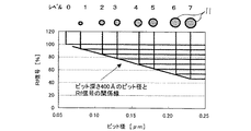
また、このような多値記録データの再生方法について説明する。ピット径(ピット占有率)とRf信号の関係を図8に示す。図4との違いは、ピット径を横軸にとっている点であり、特にここでは、ピット深さをλ/6nとしている。1つのセル13に占めるピット11の占有率(ピット占有率)の大小によって、Rf信号値は変化する。ピット11が存在しないときに最大のRf信号値となり、ピット11の占有率が最も高いときにRf信号値は最小となる。この関係を利用して、図9にピットパターン数(多値レベル数)が8の場合(レベル0,1,2,…,7)における、各ピットサイズ対応のRf信号値を示す。採用したピット11のパターンを図9中の上側に示す。
A method of reproducing such multi-valued recording data will be described. FIG. 8 shows the relationship between the pit diameter (pit occupancy) and the Rf signal. The difference from FIG. 4 is that the pit diameter is plotted on the abscissa. In particular, here, the pit depth is λ / 6n. The Rf signal value changes depending on the occupancy of the pits 11 in one cell 13 (pit occupancy). When the pit 11 does not exist, the Rf signal value becomes maximum, and when the occupancy of the pit 11 is the highest, the Rf signal value becomes minimum. Utilizing this relationship, FIG. 9 shows Rf signal values corresponding to each pit size when the number of pit patterns (the number of multilevel levels) is 8 (
即ち、各々のセル13に対するピット占有率に応じてN=8値なる多値の再生信号を生成させるとした場合、ピット11は、面積変調に応じて(N−1)=7種類の異なるピット径を有し、これらの7種類のピット径は最大ピット径のピット11による場合のセル13からの反射光量(Rf信号値は最小)とピット11なしの場合のセル13からの反射光量(Rf信号値は最大)との間をほぼN=8等分するように設定されているものである。 That is, if a multi-valued reproduction signal of N = 8 values is generated according to the pit occupancy of each cell 13, the pits 11 are (N-1) = 7 different pits according to the area modulation. The diameters of these seven types of pits are the reflected light amount (Rf signal value is minimum) from the cell 13 when the pit 11 has the maximum pit diameter and the reflected light amount (Rf) from the cell 13 when the pit 11 is not provided. The signal value is set to be approximately equal to N = 8.
従って、本実施の形態によれば、基本的に、ピット11が形成される領域が互いに等しい面積のセル13に分割され、各々のセル13に対するピット占有率に応じて多値の再生信号が生成される面積変調された1つのピット11がセル13毎に形成されることにより再生系の光記録媒体が作製されているので、深さ変調により多値情報が記録されているわけでなく、面積変調により多値情報が記録されていることとなるので、その製造工程において、ガラス基板まで露光を行う安定した現像工程を確保でき、生産性容易な多値情報が記録された再生系の光記録媒体を提供することができる。また、ピット深さとしても、プッシュプル信号振幅が最大となるλ/6nから、各ピットサイズにおける再生信号の振幅分離が最大、即ち、再生信号のS/Nが最大となるλ/4nの範囲内、特にその中間値に設定することにより、ピット11が形成された本実施の形態のような再生系の光記録媒体に対しても、記録系の光記録媒体で一般的に用いられているプッシュプル法によりトラックエラー信号を検出することが可能となる。即ち、ピット占有率により再生情報がセル単位で記録されている場合、結果的には、ピット11の連続的に並んだ構成が、ビームスポット12においては連続的な溝が形成されたものと同等に観測されるためであり、記録系の光記録媒体のトラックエラー信号の生成との互換性を取ることができる。この場合、ビームスポット12の走行方向のピット11間のエッジを観測しなくて済むため、DPD法の課題が解決されるとともに、1ビームトラッキングであるため、光効率やクロスイレースなどの問題も解消されることとなる。
Therefore, according to the present embodiment, basically, the region where pits 11 are formed is divided into cells 13 having the same area, and a multi-valued reproduction signal is generated according to the pit occupation ratio of each cell 13. Since one area-modulated pit 11 is formed for each cell 13, a reproduction type optical recording medium is manufactured, so that multi-valued information is not recorded by depth modulation. Since multi-valued information is recorded by the modulation, a stable developing process of exposing to the glass substrate can be secured in the manufacturing process, and optical recording of the reproducing system in which multi-valued information is recorded with easy productivity. A medium can be provided. The pit depth also ranges from λ / 6n, at which the push-pull signal amplitude is maximum, to λ / 4n, at which the amplitude separation of the reproduction signal at each pit size is maximum, that is, the S / N of the reproduction signal is maximum. Of these, in particular, by setting an intermediate value, a recording optical system is generally used for a reproducing optical recording medium in which the pits 11 are formed as in the present embodiment. The track error signal can be detected by the push-pull method. In other words, when the reproduction information is recorded in units of cells according to the pit occupancy, the configuration in which the pits 11 are arranged continuously is equivalent to the configuration in which continuous grooves are formed in the
本発明の第二の実施の形態を図16及び図17を参照して説明する。 A second embodiment of the present invention will be described with reference to FIGS.
本実施の形態は、前述したような再生系の光記録媒体4に対するトラックエラー信号の生成に関するもので、受光光学系と信号処理系の構成が第一の実施の形態と異なる。即ち、前述したような単純なプッシュプル法による場合、対物レンズ2の光軸が固定光学系の光軸からずれたり(シフト)、或いは傾いた(チルト)ときに受光部面上での光量分布が偏るためにトラックエラー信号にオフセットが生じる課題があるが、本実施の形態では、一般に知られる差動プッシュプル法を利用してこの課題を解決するようにしたものである。
The present embodiment relates to the generation of the track error signal for the
差動プッシュプル法(DPP法)は、光記録媒体に、グレーティングを用いて光記録媒体の主トラック上とその隣接トラック上に主光M1と第1及び第2の副光S1,S2とのスポットを形成することにより、トラックエラー信号を生成する方式である。 The differential push-pull method (DPP method) is a method in which a main light M1 and first and second sub-lights S1 and S2 are formed on a main track and an adjacent track of the optical recording medium by using a grating. In this method, a track error signal is generated by forming a spot.
グレーティングを採用した光ピックアップ(光情報処理装置の光学構成部分)を示した図16を参照すれば、半導体レーザ110から出射されたビームはコリメートレンズ111により平行光束化された後、グレーティング112で回折され、0次及び±1次回折光に分岐される。そして、この分岐された光は対物レンズ113により、図17に示すように光記録媒体114に集光照射される。この時、0次回折光である主光M1のスポットは光記録媒体114の主トラックT上に結ばれ、±1次回折光である第1及び第2の副光S1,S2のスポットは主光M1のスポットに対して先行及び後行し、光記録媒体114のラジアル方向に±1/2トラックピッチほど外れるように結ばれる。
Referring to FIG. 16 showing an optical pickup (an optical component of an optical information processing device) employing a grating, a beam emitted from a semiconductor laser 110 is collimated by a collimator lens 111 and then diffracted by a
光記録媒体114から反射されて対物レンズ113を経由した主光M1と第1及び第2副光S1,S2はビームスプリッタ115により照射光と分離され、検出レンズ116を介して受光素子117に受光される。受光素子117は図17に示すように主光M1を受光する第1光検出器118aと、第1及び第2副光S1,S2を各々受光する第2及び第3光検出器118b,118cよりなる。これらの第1ないし第3 光検出器118a〜118cは各々独立して光電変換し、光記録媒体114のラジアル方向に分割された2枚の分割板より構成される。
The main light M1 reflected from the
第1ないし第3差動増幅器119,120,121は各々第1ないし第3光検出器118a,118b,118cの検出信号が入力されて第1ないし第3プッシュプル信号を出力する。第1増幅器122は第3プッシュプル信号を所定ゲインG1に増幅し、第2増幅器123は第1増幅器122から出力される信号と第2プッシュプル信号との和信号を所定ゲインG2に増幅する。第4差動器124は第2増幅器123から入力される信号と第1差動器119から入力される主光M1による第1プッシュプル信号とを差動してトラックエラー信号を出力する。この時、第1及び第2増幅器122,123のゲインG1,G2は主光M1と第1及び第2副光S1,S2の強度を考慮して決まる。こうして、対物レンズ2が光記録媒体4のラジアル方向にシフトされるような場合であっても、プッシュプルオフセットを殆ど含まないプッシュプル信号(トラックエラー信号)を得ることができる。
The first to third
本発明の第三の実施の形態を図10及び図11に基づいて説明する。第一の実施の形態で示した部分と同一部分は同一符号を用いて示し、説明も省略する(以降の実施の形態でも同様とする)。 A third embodiment of the present invention will be described with reference to FIGS. The same parts as those described in the first embodiment are denoted by the same reference numerals, and description thereof is omitted (the same applies to the following embodiments).
本実施の形態は、前述したような再生系の光記録媒体4に対するトラックエラー信号の生成に関するもので、受光光学系と信号処理系の構成が第一、第二の実施の形態と異なる。即ち、第一の実施の形態のような単純なプッシュプル法による場合、対物レンズ2の光軸が固定光学系の光軸からずれたり(シフト)、或いは傾いた(チルト)ときに受光部面上での光量分布が偏るためにトラックエラー信号にオフセットが生じる課題がある。一方、第二の実施の形態のようなDPP法を用いた場合は、光源110から出射された光をグレーティング112により3本の光M1,S1,S2に分岐させて使用するので、(1)主光M1の光効率が低下して記録用として使用が困難となり、或いは、高速化への適用が困難となる。(2)また、記録時に第1及び第2副光S1,S2により隣接トラックに記録された信号が消去される、という問題点がある。これに対し、本実施の形態では、例えば特公平4−30094号公報に示されるような補償型のプッシュプル法を利用してこの課題を解決するようにしたものである。
This embodiment relates to the generation of the track error signal for the
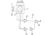
このため、受光光学系9において、光検出器としては図10に示すようにラジアル方向に4分割された分割構造の受光素子21が設けられている。この受光素子21は4つの受光領域A,B,C,Dを有するが、遠視野においてピット11からの反射0次光と反射±1次回折光とが重なる領域内で光記録媒体4のラジアル方向に対して対称に配置された一対の受光領域A,Bが第1の受光部とされ、遠視野においてピット11からの反射0次光のみの領域内で光記録媒体4のラジアル方向に対して対称に配置された一対の受光領域C,Dが第2の受光部とされている。これらの受光領域A〜Dからの検出信号をa〜dとしたとき、これらの検出信号a〜dに基づき信号処理を行いトラックエラー信号等を検出する信号処理部22が設けられている。この信号処理部22には、第1の受光部である一対の受光領域A,B間の検出信号a,bの差信号を得る差動増幅器23と、第2の受光部である一対の受光領域C,D間の検出信号c,dの差信号を得る差動増幅器24と、これらの差動増幅器23,24の演算結果を加算する加算器25とを有し、差動増幅器24と加算器25との間には補正手段としてのゲインKが可変調整可能で差動増幅器24の出力を増幅又は減少させるゲイン調整器26が介在されている。
Therefore, in the light receiving optical system 9, a
これにより、本実施の形態の場合のトラックエラー信号TE2は、
TE2=[(a−b)+K(c−d)]/[(a+b)+K(c+d)]
として算出される。この際、ゲイン調整器26のゲインKを、当該補償型のプッシュプル信号TE2に含まれるプッシュプルオフセットが最小となるように調整することにより、対物レンズ2が光記録媒体4のラジアル方向にシフトされるような場合であっても、プッシュプルオフセットを殆ど含まないプッシュプル信号(トラックエラー信号)TE2を得ることができる。
Thus, the track error signal TE2 in the case of the present embodiment is
TE2 = [(ab) + K (cd)] / [(a + b) + K (c + d)]
Is calculated as At this time, the
この点について、図11を参照して、より詳細に説明する。まず、図11は波長λが400nmの光を出射する光源1と開口数NA:0.65の対物レンズ2とを利用してトラックピッチが0.43μmの光記録媒体4のピット深さλ/6n、ピット径0.23μmのピット11に光を照射し、そこから反射された光を受光し検出した信号を示した図である。ここに、図11(b)は、通常のプッシュプル方式によるトラックエラー信号TE1を示すが、対物レンズ2のラジアル方向シフトにより実線で示すようにプッシュプルオフセットが大きく生じ、対物レンズ2のラジアル方向シフト量が大きくなるほど(x軸の右側方向に行くほど)そのプッシュプルオフセット量は増加する。
This will be described in more detail with reference to FIG. First, FIG. 11 shows a pit depth λ / of an
一方、図11(a)は図10に示したように補償型のプッシュプル法を適用することにより、対物レンズ2がラジアル方向にシフトされた場合にも、プッシュプルオフセットがほとんどないトラックエラー信号TE2を検出できる様子を示している。即ち、図10に示す構成の場合も、プッシュプル信号を構成する(a−b)、(c-d)は、各々トラックエラー信号TE1の場合と同じく、プッシュプルオフセットが相当量含まれていて、対物レンズ2のシフト量が増加するほどそのプッシュプルオフセット量が増加する。しかし、プッシュプル信号(c−d)に対してゲイン調整器26によってゲインKをかけた後で、これを加算器25でプッシュプル信号(a−b)と加算することで、図12に示すように、対物レンズ2のラジアル方向シフトに対してプッシュプルオフセットをほとんど含まないトラックエラー信号TE2が検出されるものである。
On the other hand, FIG. 11A shows a track error signal having almost no push-pull offset even when the
ところで、本実施の形態の補償型のトラックエラー信号TE2の生成方法は、前述したような本発明による再生系の光記録媒体4に限らず、記録系の光記録媒体に対しても同様に適用することができるが(互換性を有するが)、記録系の光記録媒体の情報記録面上は連続的な案内溝(グルーブ)が形成され、相変化材料などが塗布されており反射率が異なる。よって、再生系の光記録媒体に加えて、連続的な案内溝が形成された記録系の光記録媒体をも適用対象とする場合であれば、再生系の光記録媒体と記録系の光記録媒体とに応じて所定のゲインKを切換え調整するようにすれば、各々の光記録媒体の特性に適したトラックエラー信号TE2の生成が可能となる。
By the way, the method of generating the compensation type track error signal TE2 of the present embodiment is not limited to the reproduction type
また、前述したような多値情報を持たせたピット構造は、全面に形成する場合に限らず部分的とし(ピットが形成されたROM領域)、この他、連続的な案内溝が形成されたRAM領域を併有するハイブリッド型の光記録媒体を対象とする場合であれば、ROM領域とRAM領域とに応じて所定のゲインKを切換え調整するようにすれば、各々の領域の特性に適したトラックエラー信号の生成が可能となる。 In addition, the pit structure having multi-value information as described above is not limited to the case where the pit is formed on the entire surface, but is made partial (the ROM area where the pits are formed). In addition, a continuous guide groove is formed. In the case of a hybrid optical recording medium having both RAM areas, if a predetermined gain K is switched and adjusted according to the ROM area and the RAM area, the characteristic suitable for each area can be obtained. A track error signal can be generated.
本発明の第四の実施の形態を図12及び図13に基づいて説明する。本実施の形態は、基本的には、第三の実施の形態と同様であり、補償型のプッシュプル法を適用したものであるが、その受光光学系9に関して、4分割された分割構造の受光素子21に代えて、ホログラム素子(回折素子)31と複数の受光素子32A〜32Dとの組合せ構成を利用したものである。
A fourth embodiment of the present invention will be described with reference to FIGS. This embodiment is basically the same as the third embodiment, and employs a compensation-type push-pull method. However, the light receiving optical system 9 has a four-divided divided structure. Instead of the
まず、ホログラム素子31は前述の受光素子21の場合と同様に、ラジアル方向に対して4分割された4つの回折領域A,B,C,Dを有するが、遠視野においてピット11からの反射0次光と反射±1次回折光とが重なる領域内で光記録媒体4のラジアル方向に対して対称に配置されて入射光を互いに異なる角度に1次回折させるホログラムパターンが形成された一対の回折領域A,Bを有し、かつ、遠視野においてピット11からの反射0次光のみの領域内で光記録媒体4のラジアル方向に対して対称に配置されて入射光を互いに異なる角度に1次回折させるホログラムパターンが形成された一対の回折領域C,Dを有する。そして、回折領域A,Bにより回折偏向された光を受光する位置に配設させた受光素子32A,32Bとの組合せにより第1の受光部が構成され、回折領域C,Dにより回折偏向された光を受光する位置に配設させた受光素子32C,32Dとの組合せにより第2の受光部が構成されている。
First, the
本実施の形態の場合、受光光学系9中にホログラム素子31が介在されているが、受光素子32A〜32Dの検出信号a〜d自体は受光素子21による検出信号a〜dの場合と同じであり、詳細は省略するが、図10に示した信号処理部22と同じ構成でプッシュプルオフセットが最小となるようにトラックエラー信号TE2を生成することができる。
In the case of the present embodiment, the
従って、本実施の形態の場合も、第三の実施の形態の場合と同様にプッシュプルオフセットの影響を受けないトラックエラー信号TE2の生成が可能であるが、受光素子32A〜32Dの前段に分割構造のホログラム素子31を介在させ、遠視野における反射光を受光素子32A〜32Dに向けて回折偏向させることで、受光素子32A〜32Dの構成・配置の自由度が増すこととなる。
Therefore, also in the case of the present embodiment, it is possible to generate the track error signal TE2 which is not affected by the push-pull offset as in the case of the third embodiment, but it is possible to generate the track error signal TE2 before the
3 照射光学系
4 光記録媒体
9 受光光学系
11 ピット
13 セル
21 第1の受光部
22 信号処理部
26 補正手段
31 回折素子
32A〜32D 受光素子
Claims (12)
前記ピットが形成される領域が互いに等しい面積のセルに分割され、各々のセルに対するピット占有率に応じて多値の再生信号が生成される面積変調された単一のピットが前記セル毎に形成され、各々の前記ピットの深さHは、照射されるレーザ光の波長をλ、当該媒体基板の屈折率をnとしたとき、
λ/6n<H<λ/4n
を満足する光記録媒体。 In an optical recording medium in which a reproduction signal is generated from a reflected light amount of a laser beam applied to a pit,
The area in which the pits are formed is divided into cells having the same area, and a single area-modulated pit in which a multi-valued reproduction signal is generated according to the occupancy of each cell is formed for each cell. The depth H of each of the pits is, when the wavelength of the laser light to be irradiated is λ, and the refractive index of the medium substrate is n,
λ / 6n <H <λ / 4n
Optical recording medium that satisfies the following.
前記ピットは、面積変調に応じて(N−1)種類の異なるピット径を有し、これらの(N−1)種類のピット径は最大ピット径のピットによる場合のセルからの反射光量とピットなしの場合のセルからの反射光量との間をほぼN等分するように設定されている請求項1又は2記載の光記録媒体。 A multi-valued reproduction signal of N values is generated in accordance with the pit occupancy of each of the cells;
The pits have (N-1) kinds of different pit diameters according to the area modulation, and these (N-1) kinds of pit diameters are the amount of light reflected from the cell and the pit diameter when the pits have the maximum pit diameter. The optical recording medium according to claim 1, wherein the optical recording medium is set so as to divide the amount of light reflected from the cell in the case where no cell is provided into approximately N equally.
前記光記録媒体からの反射光を受光する受光光学系と、
この受光光学系が受光した検出信号に基づき信号処理を行う信号処理部と、
を有し、
前記受光光学系は、遠視野における前記ピットからの反射0次光と反射±1次回折光とが重なる領域内で前記光記録媒体のラジアル方向に対して対称に配置された少なくとも一対の第1の受光部を有し、
前記信号処理部は、前記第1の受光部の検出信号の差に基づきトラックエラー信号をプッシュプル法により検出する、
光情報処理装置。 An irradiation optical system for converging and irradiating a pit formed on the optical recording medium according to any one of claims 1 to 4 with laser light.
A light receiving optical system for receiving reflected light from the optical recording medium,
A signal processing unit that performs signal processing based on the detection signal received by the light receiving optical system;
Has,
The light receiving optical system includes at least a pair of first symmetrically arranged with respect to a radial direction of the optical recording medium in a region where a reflected zero-order light and a reflected ± first-order diffracted light from the pit in a far field overlap. Has a light receiving section,
The signal processing unit detects a track error signal by a push-pull method based on a difference between detection signals of the first light receiving unit.
Optical information processing device.
前記信号処理部は、トラックエラー信号として前記第1の受光部の検出信号の差を前記第2の受光部の検出信号の差により補正する補正手段を備える、
請求項5記載の光情報処理装置。 The light receiving optical system includes, in addition to the first light receiving unit, at least one pair of symmetrically arranged in the radial direction of the optical recording medium in a region of only the zero-order light reflected from the pit in a far field. A second light receiving unit,
The signal processing unit includes a correction unit that corrects a difference between detection signals of the first light receiving unit as a track error signal by using a difference between detection signals of the second light receiving unit.
The optical information processing device according to claim 5.
TE=[(a−b)+K(c−d)]/[(a+b)+K(c+d)]
として算出する、
請求項6記載の光情報処理装置。 When the detection signals of the first light receiving portions A and B are a and b and the detection signals of the second light receiving portions C and D are c and d, the correction means adjusts a predetermined gain K. And the track error signal TE is
TE = [(ab) + K (cd)] / [(a + b) + K (c + d)]
Calculated as
The optical information processing device according to claim 6.
請求項7記載の光情報処理装置。 The correction means adjusts a predetermined gain K such that an offset component included in the track error signal TE is minimized;
The optical information processing device according to claim 7.
前記補正手段は、再生系の光記録媒体と記録系の光記録媒体とに応じて所定のゲインKを切換え調整する、
請求項7又は8記載の光情報処理装置。 In addition to the reproducing optical recording medium according to any one of claims 1 to 4, a recording optical recording medium having a continuous guide groove is applied,
The correction means switches and adjusts a predetermined gain K according to a reproduction system optical recording medium and a recording system optical recording medium.
An optical information processing apparatus according to claim 7.
請求項7又は8記載の光情報処理装置。 In the case where the optical recording medium is a hybrid optical recording medium having a RAM area in which continuous guide grooves are formed in addition to a ROM area in which pits are formed, the correction means comprises a ROM area and a RAM. Switching and adjusting a predetermined gain K according to the region;
An optical information processing apparatus according to claim 7.
The first and second light receiving sections are arranged symmetrically with respect to a radial direction of the optical recording medium, and have a divided structure for diffracting and deflecting reflected light in a far field in a predetermined direction. The optical information processing apparatus according to claim 6, comprising a combination of a plurality of light receiving elements for receiving the light.
Priority Applications (4)
| Application Number | Priority Date | Filing Date | Title |
|---|---|---|---|
| JP2003339564A JP2004281027A (en) | 2003-02-24 | 2003-09-30 | Optical recording medium and optical information processing device |
| US10/537,830 US7382715B2 (en) | 2003-02-24 | 2004-02-20 | Optical recording medium having relationship between pit depths, wavelength and refractive index |
| EP04713220A EP1599872A2 (en) | 2003-02-24 | 2004-02-20 | Medium for optical recording and apparatus for optical information processing |
| PCT/JP2004/002046 WO2004074908A2 (en) | 2003-02-24 | 2004-02-20 | Medium for optical recording and apparatus for optical information processing |
Applications Claiming Priority (2)
| Application Number | Priority Date | Filing Date | Title |
|---|---|---|---|
| JP2003046417 | 2003-02-24 | ||
| JP2003339564A JP2004281027A (en) | 2003-02-24 | 2003-09-30 | Optical recording medium and optical information processing device |
Publications (1)
| Publication Number | Publication Date |
|---|---|
| JP2004281027A true JP2004281027A (en) | 2004-10-07 |
Family
ID=32911440
Family Applications (1)
| Application Number | Title | Priority Date | Filing Date |
|---|---|---|---|
| JP2003339564A Pending JP2004281027A (en) | 2003-02-24 | 2003-09-30 | Optical recording medium and optical information processing device |
Country Status (4)
| Country | Link |
|---|---|
| US (1) | US7382715B2 (en) |
| EP (1) | EP1599872A2 (en) |
| JP (1) | JP2004281027A (en) |
| WO (1) | WO2004074908A2 (en) |
Families Citing this family (3)
| Publication number | Priority date | Publication date | Assignee | Title |
|---|---|---|---|---|
| KR20080075916A (en) * | 2005-12-13 | 2008-08-19 | 코닌클리케 필립스 일렉트로닉스 엔.브이. | Radial tilt estimation via diagonal push-pull |
| JP2007207357A (en) * | 2006-02-02 | 2007-08-16 | Canon Inc | Optical information reproducing method and device |
| WO2008059952A1 (en) * | 2006-11-16 | 2008-05-22 | Panasonic Corporation | Optical information reproducing device tracking apparatus |
Family Cites Families (21)
| Publication number | Priority date | Publication date | Assignee | Title |
|---|---|---|---|---|
| JPS58215735A (en) | 1982-06-07 | 1983-12-15 | Sony Corp | Optical disc recording method |
| JPH0430094A (en) | 1990-05-26 | 1992-02-03 | Kumagai Gumi Co Ltd | Starting device and starting method of shield excavator for inclined shaft |
| EP0578015B1 (en) * | 1992-06-17 | 1998-12-09 | Matsushita Electric Industrial Co., Ltd. | Optical information recording medium |
| JPH07121881A (en) | 1993-10-27 | 1995-05-12 | Hitachi Ltd | Optical information recording and reproducing method |
| US5602825A (en) * | 1994-01-19 | 1997-02-11 | Kabushiki Kaisha Toshiba | Optical disk and optical disk apparatus |
| US5757763A (en) | 1994-07-12 | 1998-05-26 | Massachusetts Institute Of Technology | Optical information storage via amplitude modulation |
| KR100454379B1 (en) * | 1995-12-28 | 2004-12-17 | 소니 가부시끼 가이샤 | Optical Disk |
| JP3065529B2 (en) * | 1996-03-12 | 2000-07-17 | 株式会社リコー | Optical information recording medium and tracking servo method for optical information recording medium |
| US6175548B1 (en) * | 1998-06-29 | 2001-01-16 | Sony Corporation | Optical recording medium and optical recording and reproducing apparatus |
| JP3866016B2 (en) * | 1999-07-02 | 2007-01-10 | Tdk株式会社 | Optical information medium and reproducing method thereof |
| US6678236B1 (en) * | 1999-08-24 | 2004-01-13 | Victor Company Of Japan, Ltd. | Information recording medium method and apparatus for recording and reproducing information |
| JP3490356B2 (en) * | 1999-09-29 | 2004-01-26 | シャープ株式会社 | Optical recording medium, master for optical recording medium and method of manufacturing the same |
| KR100644581B1 (en) | 1999-10-30 | 2006-11-13 | 삼성전자주식회사 | Tracking error signal detecting apparatus and reproducing signal detecting apparatus |
| EP2113916B1 (en) * | 1999-11-25 | 2010-09-01 | Victor Company of Japan Ltd. | Optical information recording medium, and substrate and manufacturing method for the optical information recording medium |
| JP2001291244A (en) * | 2000-04-04 | 2001-10-19 | Sharp Corp | Optical recording medium, method and device for reproducing optical recording information |
| KR100636121B1 (en) * | 2000-05-23 | 2006-10-18 | 삼성전자주식회사 | Optical pickup apparatus |
| KR100694036B1 (en) * | 2000-06-01 | 2007-03-12 | 삼성전자주식회사 | Disc with grooves and pits of different depths and method for manufacturing thereof |
| US6808778B2 (en) | 2000-07-04 | 2004-10-26 | Tdk Corporation | Optical recording medium |
| JP2002117539A (en) * | 2000-10-10 | 2002-04-19 | Tdk Corp | Optical recording medium |
| JP3914704B2 (en) | 2000-11-17 | 2007-05-16 | 株式会社リコー | Multi-value recording / reproducing optical information recording medium, recording / reproducing method and recording / reproducing apparatus using the same |
| KR100408401B1 (en) | 2001-02-23 | 2003-12-06 | 삼성전자주식회사 | Optical recording/reproducing apparatus and method for detecting tracking error signal |
-
2003
- 2003-09-30 JP JP2003339564A patent/JP2004281027A/en active Pending
-
2004
- 2004-02-20 US US10/537,830 patent/US7382715B2/en not_active Expired - Fee Related
- 2004-02-20 WO PCT/JP2004/002046 patent/WO2004074908A2/en active Application Filing
- 2004-02-20 EP EP04713220A patent/EP1599872A2/en not_active Withdrawn
Also Published As
| Publication number | Publication date |
|---|---|
| EP1599872A2 (en) | 2005-11-30 |
| WO2004074908A3 (en) | 2005-01-27 |
| US7382715B2 (en) | 2008-06-03 |
| WO2004074908A2 (en) | 2004-09-02 |
| US20060013119A1 (en) | 2006-01-19 |
Similar Documents
| Publication | Publication Date | Title |
|---|---|---|
| US7558170B2 (en) | Optical pick-up head, optical information apparatus, and optical information reproducing method | |
| USRE42825E1 (en) | Optical pickup head device, information recording/reproducing apparatus, and method for recording information | |
| JP2007122779A (en) | Optical pickup and optical disk apparatus | |
| US7095686B2 (en) | Defocus error signal detection apparatus having phase comparators and a matrix circuit for an optical recording/reproduction system | |
| EP1755116A2 (en) | Optical pickup apparatus capable of detecting and compensating for spherical aberration caused by thickness variation of recording layer | |
| KR20080021120A (en) | An optical system with 3 spot radial tracking | |
| JP2004281027A (en) | Optical recording medium and optical information processing device | |
| US20100118684A1 (en) | Information recording and reproducing device | |
| US6147952A (en) | Optical disk apparatus for reproducing information from an optical recording medium | |
| KR100659293B1 (en) | Diffraction element and optical pick-up apparatus having the same | |
| US6373808B1 (en) | Optical pick-up apparatus capable of eliminating a cross-talk component from adjacent tracks | |
| JP4153195B2 (en) | Land / groove discrimination method and optical recording / reproducing apparatus | |
| US20100149951A1 (en) | Information recording and reproducing device | |
| US20100135140A1 (en) | Information recording and reproducing device | |
| KR100692574B1 (en) | Diffraction element and optical pick-up apparatus having the same | |
| JP2005339751A (en) | Optical reproducing method, optical pickup device, optical reproducing device, and optical recording medium | |
| KR100624864B1 (en) | Optical pick-up and method for detecting spherical aberration signal | |
| US20070247984A1 (en) | Optical Record Carrier and Optical Scanning Device | |
| JP2006179047A (en) | Optical information recording medium and optical information processing apparatus | |
| JP2005276391A (en) | Optical pickup device | |
| JPH0636339A (en) | Optical reproducing device |
Legal Events
| Date | Code | Title | Description |
|---|---|---|---|
| RD04 | Notification of resignation of power of attorney |
Free format text: JAPANESE INTERMEDIATE CODE: A7424 Effective date: 20041013 |
|
| RD01 | Notification of change of attorney |
Free format text: JAPANESE INTERMEDIATE CODE: A7421 Effective date: 20051021 |
|
| A621 | Written request for application examination |
Free format text: JAPANESE INTERMEDIATE CODE: A621 Effective date: 20060807 |
|
| RD01 | Notification of change of attorney |
Free format text: JAPANESE INTERMEDIATE CODE: A7421 Effective date: 20060905 |
|
| A131 | Notification of reasons for refusal |
Free format text: JAPANESE INTERMEDIATE CODE: A131 Effective date: 20080916 |
|
| A521 | Written amendment |
Free format text: JAPANESE INTERMEDIATE CODE: A523 Effective date: 20081114 |
|
| A02 | Decision of refusal |
Free format text: JAPANESE INTERMEDIATE CODE: A02 Effective date: 20090721 |