JP2004280010A - Display device having blazed diffraction grating pattern - Google Patents
Display device having blazed diffraction grating pattern Download PDFInfo
- Publication number
- JP2004280010A JP2004280010A JP2003075015A JP2003075015A JP2004280010A JP 2004280010 A JP2004280010 A JP 2004280010A JP 2003075015 A JP2003075015 A JP 2003075015A JP 2003075015 A JP2003075015 A JP 2003075015A JP 2004280010 A JP2004280010 A JP 2004280010A
- Authority
- JP
- Japan
- Prior art keywords
- diffraction grating
- pattern
- blazed
- diffraction
- display
- Prior art date
- Legal status (The legal status is an assumption and is not a legal conclusion. Google has not performed a legal analysis and makes no representation as to the accuracy of the status listed.)
- Pending
Links
Images


Landscapes
- Diffracting Gratings Or Hologram Optical Elements (AREA)
Abstract
Description
【0001】
【発明の属する技術分野】
本発明は、画像表示やセキュリティ(偽造防止)の用途に好適であって、微小な回折格子セルが複数個配置されていると共に、それらの内の所望の回折格子セルの組合せにより複数の回折格子パターンが構成されており、この複数の回折格子パターンに対応して複数の画像が観察されるようになっているディスプレイに関する。
【0002】
【従来の技術】
従来から、動画像、あるいは視点を変えることによって変化する画像を、平面状の基板上で表現させる方法として、レンチキュラー・レンズを使用する画像チェンジング技術や、ホログラフィック・ステレオグラムやホログラムを利用した画像チェンジング技術がある。また、複数の微小な回折格子から構成される回折格子パターンを用いた画像チェンジング技術もある。(例えば、特許文献1参照。)
【0003】
回折格子から構成される回折格子パターンは、通常の印刷技術では表現することのできない指向性のある光沢や色彩を表現できることから、ディスプレイの用途や偽造防止を目的とするセキュリティ商品等に広く用いられている。そして、このような回折格子パターンやこの回折格子パターンを有するディスプレイ等においては、より多彩でオリジナリティの高いものを作製することが求められている。
【0004】
ところで、このような従来の画像チェンジング技術の中で、レンチキュラー・レンズを使用するものでは、光源の位置を変えても観察者が移動しなければ画像の変化を観察することはできなかった。また、ホログラフィック・ステレオグラムやホログラムを利用した画像チェンジング技術では、複数の画像が同時に目に入ったり、ボケが生じ、クリアーな画像を表現することが難しかった。
【0005】
一方、回折格子を用いた従来の画像チェンジングは、任意の空間周波数のバイナリー型回折格子を有する微小な回折格子セルを複数個用いて最初の回折格子パターンを基板上に形成し、次に前記回折格子パターンを構成する回折格子セルの回折格子方向とは異なる回折格子方向に設定された任意の空間周波数のバイナリー型回折格子を有する微小な回折格子セルを複数個用いて次の回折格子パターンを同一の基板上に形成し、以後、所望の回折格子パターンの数だけ上記と同様の操作を繰り返し、次々と回折格子パターンを同一の基板上に形成するようにし、光源、または観察者、若しくは基板の3つの要素の相対的な位置を変えることにより、複数の回折格子パターンに対応する複数の画像を比較的にクリアーに表現できるようにした方法である。
【0006】
そして、回折格子パターンを作製する方法としては、例えばレーザー光の2光束干渉により得られる干渉縞(回折格子)を有する微小なドット(回折格子セル)を、そのピッチ、方向、および光強度を変化させて、感光性フィルムに次々とパターン状に露光する方法が採られる(例えば、特許文献2参照。)。
【0007】
一方、レーザー光ではなく電子ビーム露光装置からの電子ビームを用い、平面状の基板が載置されたX−Yステージの移動をコンピューターにより制御しながら基板の表面に回折格子からなる複数の微小なドット(回折格子セル)をパターン状に配置することにより、回折格子パターンを作製する方法も提案されている(例えば、特許文献3参照。)。
【0008】
このようにして基板表面に形成される回折格子パターンのパラメータとしては、回折格子の空間周波数あるいは格子間隔(格子のピッチ)と、回折格子の方向(回折格子方向)と、回折格子パターンを構成する微小な回折格子セルの配置の3つがある。そして、回折格子の空間周波数あるいは格子間隔(格子のピッチ)を変化させることによって見える色が変化し、また回折格子の方向(回折格子方向)を変化させることによって光って見える方向が変化し、さらには、回折格子パターンを構成する回折格子セルの配置の仕方により表示する画像(絵柄)が決定される。
【0009】
また、回折格子に照射する入射光の波長や入射角度と、回折格子の格子間隔とその回折格子から出射する回折光の出射角度との関係は、以下のように説明される。すなわち、図6は回折格子セル5に特定角度で波長λの単色の入射光1を入射した場合に観察される回折光の状態を示しているが、このような状態において、回折格子セル5の面に垂直な任意の面における回折格子セルによる任意の次数に対する回折現象は以下の式で表される。
d=mλ/(sinα−sinβ)
【0010】
図6ならびに上式において、dは着目した面における回折格子の格子間隔(空間周波数の逆数)、mは回折次数、αは当該面における0次回折光3(照明光の透過光あるいは正反射光であり、図6では正反射光にあたる)の出射角度、βは当該面における1次回折光2の出射角度(回折角)である。
従って、このような関係を踏まえ、回折格子セル面をX−Y平面とし、それに直交するX−Z平面およびY−Z平面について、3次元空間における回折光の方向などを所望の状態で様々に設定することができるようになる。
【0011】
しかし、このような関係を配慮して基板表面に形成された回折格子パターンは、設計上は異なる複数の回折格子パターンに対応する複数の画像が変化して観察できる状況であっても、前に観察されていた画像に対応する回折格子のノイズ及び基板表面の凹凸による散乱により、前に観察されていた画像が新たに見えてきた画像とオーバーラップしてぼんやりと見えてしまい、画像の切り替えが明瞭に行えなかった。
【0012】
また、回折格子としては種々の形態のものがあるが、前述した回折格子を利用した画像チェンジングにおいて、回折格子としてバイナリー型を採用した場合には、画像チャンジング技術で複数の画像を表現できる範囲はその画像に対応する回折格子パターンの回折方向が0度から180度未満での範囲に制限されてしまう。例えば、回折格子の格子方向が45度ごとに異なる回折格子パターンの場合、図11に示すように、回折格子パターンに対応する4種の画像しか表現できない。要するに、バイナリー型回折格子においては、回折格子方向が0度と180度は同等であることを意味し、画像チェンジングにおいて表現し得るチェンジング画像の数が少ないという欠点を有していた。
【0013】
【特許文献1】
特許第2630047号明細書
【特許文献2】
特開昭60−156004号公報
【特許文献3】
特開平2−72320号公報
【0014】
【発明が解決しようとする課題】
本発明は以上のような状況に鑑みなされたものであって、複数の微小な回折格子セルが基板表面に配置されていると共に、それらの内の所望の回折格子セルの組合せにより複数の回折格子パターンが複数構成されており、この複数の回折格子パターンに対応して複数の画像が観察されるようになっているディスプレイであって、観察される画像の明るさを向上させると共に、画像チェンジングが鮮明に行えることを可能とし、併せて画像チェンジングに関与する回折格子パターンの数もより多く設定できるようにしたことを特徴とするブレーズド型回折格子パターンを有するディスプレイの提供を目的とする。
【0015】
【課題を解決するための手段】
本発明は、上記の課題を解決するためになされたものであり、請求項1に記載の発明は、平面状の基板の表面に複数の微小な回折格子セルが配置されていると共に、それらの内の所望の回折格子セルの組合せにより複数の回折格子パターンが構成されており、この複数の回折格子パターンの個々に対応してそれぞれの画像が観察されるようになっているディスプレイにおいて、一個の回折格子パターンを構成する複数の回折格子セルはその回折格子方向が同一方向に設定されていて、かつそれ以外の回折格子パターンを構成する複数の回折格子セルの回折格子方向とは異なるように設定されていると共に、複数の回折格子パターンの少なくとも一つは、それを構成する複数の微小な回折格子セルの回折格子がブレーズド型回折格子であることを特徴とするブレーズド型回折格子パターンを有するディスプレイである。
【0016】
また、請求項2に記載の発明は、請求項1に記載のブレーズド型回折格子パターンを有するディスプレイにおいて、回折格子パターンを構成する回折格子セルの回折格子はいずれもブレーズド型回折格子であることを特徴とする。
【0017】
さらにまた、請求項3に記載の発明は、請求項1または2に記載のブレーズド型回折格子パターンを有するディスプレイおいて、回折格子パターンを構成する回折格子セルの回折格子方向はその他の回折格子パターンを構成する回折格子セルの回折格子方向とは5度以上異なっていることを特徴とする。
【0018】
さらにまた、請求項4に記載の発明は、請求項1ないし3のいずれかに記載のブレーズド型回折格子パターンを有するディスプレイにおいて、複数の回折格子パターンが同一領域にあり、それらの占める面積が同一であることを特徴とする。
【0019】
さらにまた、請求項5に記載の発明は、請求項1ないし4のいずれかに記載のブレーズド型回折格子パターンを有するディスプレイにおいて、回折格子パターを構成する回折格子セルは他の回折格子パターンを構成する回折格子セルと互いに隣接するように配置されていることを特徴とする。
【0020】
ここで、ブレーズド回折格子とは、図9に示すように、鋸刃状の断面形状を持つ回折格子であり、その斜面での入射光の反射もしくは屈折の角度が、回折角度と一致した場合、後述するバイナリー型回折格子に比べて非常に高い回折効率が得られることが知られている。また、図10に示すような階段状の断面形状を持つ回折格子においても高い回折効率が得られることが知られている。本明細書においてはこの階段状の回折格子もブレーズド型回折格子に含むものとする。
【0021】
また、バイナリー型回折格子とは、一般的には図8に示すような矩形波状の断面形状を持つ回折格子である。このような断面形状を有するプレス版を用いて作製される熱エンボス複製品等においては、例えばレリーフ型ホログラムに見られるような正弦波状に近い断面形状の回折格子が賦型されるのが一般的であり、本明細書ではこのような正弦波状の回折格子もバイナリー型回折格子に含むものとする(図7参照)。
【0022】
【発明の実施の形態】
以下、本発明の実施の形態を図面に基づいて説明する。なお、全ての図面はわかり易いように実際の回折格子や格子間隔の大きさよりも拡大して表現している。
【0023】
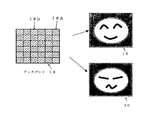
図1は本発明のディスプレイ18とこのディスプレイ18に内在する2種類のブレーズド型回折格子パターンにより表現し得る2種類の画像19、20の概略がそれぞれ示してある。
このディスプレイ18は、平面状の基板(図示せず)の表面に2種類の微小な回折格子セル18A、18Bがそれぞれ複数個配置されていると共に、それぞれの回折格子セル18A、18Bの組合せにより2種類の回折格子パターンが構成されており、この2種類の回折格子パターンに対応して2種類の画像19、20がそれぞれ観察されるようになっている。そして、一方の回折格子パターンを構成する複数の回折格子セル18A・・・はその回折格子方向が同一方向に設定されて(回折格子方向が右斜め下方向)、かつ他方の回折格子パターンを構成する複数の回折格子セル18B・・・の回折格子方向(回折格子方向が左斜め下方向)とは異なるように設定されていると共に、各回折格子パターンを構成する2種類の回折格子セル18A、18Bの回折格子がブレーズド型回折格子となっている。
【0024】
この2種類の微小な回折格子セル18A、18Bは、個々の外形は同一形状で、それぞれの回折格子方向は90度異なっており(一方が右斜め下向きで他方が左斜め下向き)、かつ各回折格子セルは互いに隣接するように組み合わされて1つ基板表面に配置されていて、ディスプレイ18を構成している。
【0025】
図示の実施形態では、回折格子パターンを構成する回折格子セル18A、18Bとしてはその外形が矩形状のもが適用されていて、さらに観察者から個々の回折格子セル18A・・・、18B・・・の存在を認識できないようにするため、その大きさを300μm以下にしてある。そして、2種類の回折格子パターン18A、18Bの表現領域は同一領域内に位置するように設定している。本発明のディスプレイ中の回折格子セルの外形は、上述した矩形状のものに限定されるものではなく、三角形状、円形状、多角形状等の種々の形状のものが適用され得る。
【0026】
ところで、上述した2種類の回折格子セルで構成される2種類の回折格子パターンの表現領域が同一となるように設定されていない場合には、単一の回折格子パターンのみが表現されている領域が存在することになり、一方の回折格子パターンのみを見せたい場合でも種々の光学的ノイズや散乱で他方の回折格子パターンが分かってしまう。しかし、複数の回折格子パターンの表現領域が同一じである場合には、回折格子パターンを構成する回折格子セルの回折格子をブレーズド型にして回折効率を向上させ、回折光の明るさを明るくすることで他の回折格子パターンのノイズ等が隠蔽できるようになり、上述のような心配無しに画像チェンジングが明瞭に行えるようになる。
また、本実施形態のように一方の回折格子パターンを構成する回折格子セルを他方の回折格子パターンを構成する回折格子セルと隣接するように配置することでさらに他の回折格子パターンのノイズや散乱を緩和でき、観察される画像をより鮮明に表現することができるようにもなる。
【0027】
このような構成のディスプレイ18に対して右斜め下に設置した光源23から光を照射すると、図2に示すように、ブレーズド型回折格子を有する回折格子セル18Aからなる回折格子パターンに対応して画像21が観察者24に明瞭に認識される。これは、前述したように、この回折格子パターンを構成する回折格子セル18Aの回折格子をブレーズド型としたからであり、しかも一方の回折格子パターンを構成する回折格子セルを他方の回折格子パターンを構成する回折格子セルと隣接するように配置したからである。
もしも回折格子セルの回折格子が従来のようにバイナリ−型の場合には他の画像もぼんやりと見えてしまう(画像22参照)。
【0028】
一方、図3に示すように、ディスプレイ18に対して左斜め下に設置した光源23から光を照射すると、今度は別個の画像25に切り替わってそれが観察者24に明瞭に認識されるようになる。この場合においても、もしも回折格子パターンを構成する回折格子セルの回折格子がバイナリ−型の場合には他の画像もぼんやりと見えてしまうことになる(画像26参照)。
【0029】
このように、バイナリー型回折格子を利用した従来の画像チェンジング技術では、設計上では隠れている画像でも回折格子のノイズや基板表面の凹凸による散乱で画像がぼんやりと見えることがあるのに対し、本発明のように回折格子パターンを構成する回折格子セルの回折格子をブレーズド型とすることにより、回折格子パターンに対応して観察される画像の明るさが2〜3倍向上し、他の回折格子パターンのノイズや散乱を緩和できるようになり、画像チェンジングに際して不要な画像(隠蔽すべき画像)がぼんやりと見えることがなくなる。
【0030】
これは、バイナリー型回折格子のように断面形状が左右対称な回折格子では、正方向と負方向からの入射光に対する回折光の回折効率はほぼ一致するため、その差は殆ど目視で判断することができないのに対し、断面形状が左右対称でないブレーズド型回折格子では、回折光の回折効率は正方向と負方向からの入射光に対して回折効率が大きく異なり、その差は目視や機械読み取りによって明瞭に区別することができるようになるからである。
【0031】
以下、この現象を図4ならびに図5により詳細に説明する。
図4には、ブレーズド型回折格子10に対して正方向の入射光6(上から照射する入射光)と負方向の入射光11(下から照明する入射光)をそれぞれ入射したときの回折光8と回折光12の見え方の違いが、また図5には、バイナリー型回折格子13に対して正方向の入射光7(上から照射する入射光)と負方向の入射光16(下から照明する入射光)をそれぞれ入射したときの回折光15と回折光17の見え方の違いが概念的に示してある。
図からも明らかなように、ブレーズド型回折格子10の場合は、正方向から入射光6を照明すると回折光8が著しく明るく観察者9に認識されるが、負方向から入射光11を照明すると回折光12が極僅かであるか見えないほど暗く観察者9に認識される(図4参照)。一方、バイナリー型回折格子13の場合は、正方向から入射光14を照射した場合でも負方向から入射光16を照射した場合でも見え方に変化ない(図5参照)。
したがって、回折格子を利用した画像チェンジングにおいては、ブレーズド型回折格子を用いることにより、前述したように、回折光の回折効率は正方向と負方向からの入射では回折効率が大きく異なり、その差は目視や機械読み取りによって明瞭に区別することができるようになり、画像の切り換えが適格に認識されるようになる。
この場合、回折格子パターンを構成する回折格子セルの回折格子を全てブレーズド型とすると画像チェンジングが鮮鋭に行われるようになる訳であるが、本発明はこれに限定されるものではなく、複数の回折格子パターンの内の少なくとも一つの回折格子パターンを構成する回折格子セルの回折格子をブレーズド型とすることにより画像チェンジングが従来に較べてより明瞭に認識されるようになる。
【0032】
一方、ある回折格子パターンを構成する回折格子の回折格子方向と他の回折格子パターンを構成する回折格子の回折格子方向の方向角度差が5度未満の場合は、それぞれの回折格子パターンが重複して現れ易くなるため、動画を描写する用途のような場合を除いては使用しないほうが好ましい。ただし、照射光を太陽光とする場合には5度程度の方向角度差で十分であるが、ハロゲンランプのような点光源からの光を照射する場合には10度以上、蛍光灯のような広い発光部分を有する光源や点光源が複数存在する場合には各回折格子の方向角度差は20度以上となるようにすることが好ましい。
【0033】
図12にはブレーズド型回折格子を用いた回折格子パターンがそれらを構成する回折格子セルのバイナリー回折格子の回折格子方向を45度の方向角度差で設定された場合に観察される画像が示してあるが、図からも明らかなように、ブレーズド型回折格子を用いると0度、45度、90度、135度、180度、225度、270度、315度の8種類までが表示、観察できるようになる。前述したようにバイナリー型回折格子を利用した従来のディスプレイでは180度の範囲内でしか表現できないが、ブレーズド型回折格子を用いたディスプレイでは360度の範囲に渡ってチェンジング画像を表現できる。
すなわち、ブレーズド型回折格子を用いた画像チェンジングにおいては、一つの基板表面上で視点を変えることによって変化できる最大画像の数は、バイナリー型回折格子を利用したものの2倍とすることが可能となる。
【0034】
またこのような構成のディスプレイは、静止した観察者が光源を動かした状態で観察すると、図2、図3に示すような画像21と画像25が次々に見える。また、複数の回折格子パターンのそれぞれの回折格子パターンが連続した動作を順次表現したものであれば、アニメーションの効果も見られるようになる。さらに、同一の位置に複数のメッセージを順次表示するようにしたり、複数の回折格子パターンを同時に表示するようにすることによって、様々な画像表現が可能となる。
【0035】
図示の実施形態では、同一の断面形状の回折格子をその回折格子方向のみを変えることで画像表現を実現させる例を示したが、本発明はこれに限定されるものではなく、回折格子の種類や方向を様々に組み合わせることで、一層多彩でセキュリティー性を向上させて画像を現出させることができる。
【0036】
因みに、このようなブレーズド型回折格子パターンを有するディスプレイは、これらの表面形状を元にメッキなどによりスタンパ(複製用版)を得、このスタンパにより熱可塑性樹脂にエンボス成形を施したり、UV硬化樹脂でUV成形することで、安価に大量複製される。
【0037】
【発明の効果】
以上説明したように、本発明のディスプレイにおいては、観察者が視点を変えた場合に、異なった画像を観察できる。また、静止した観察者の場合にも、光源の位置を変えることによって光源の位置に応じた異なる画像を観察することができる。さらに、静止した光源によって静止した観察者がこのディスプレイを観察する場合でも、ディスプレイを任意に移動させることによって、異なる画像を観察することができる。
【0038】
また、回折光の強弱が入射する光の方向性に依存するため、鮮明で的確な画像チェンジングが行える。
さらにまた、画像チェンジングする前に見えていた画像に対応する回折格子パターンを構成する回折格子セルの回折格子のノイズや基板表面の凹凸による散乱が画像チェンジング後に見えてくる画像に与える影響も、回折格子パターン自体の回折効率(明るさ)を向上させることで緩和することができ、併せて一つのディスプレイの同じ位置において表現できるチェンジング画像の数を従来のバイナリー型回折格子パターンを用いたディスプレイにおいて表現可能なチェンジング画像の数の2倍とすることができる。
【図面の簡単な説明】
【図1】本発明のディスプレイの概略の構成とこのディスプレイにおいて観察されるチェンジング画像の概略を示す説明図である。
【図2】本発明のディスプレイに対して右下から光線を照射しているときの状態とこのときに観察される画像、並びに正弦波状のバイナリー型回折格子を用いたディスプレイにおいて観察される画像を示す説明図である。
【図3】本発明のディスプレイに対して左下から光線を照射しているときの状態とこのときに観察される画像、ならびに正弦波状のバイナリー型回折格子を用いたディスプレイにおいて観察される画像を示す説明図である。
【図4】ブレーズド型回折格子のに対して正方向と負方向から入射光を照射たときに観察される回折光の様子を示す説明図である。
【図5】バイナリー型回折格子のに対して正方向と負方向から入射光を照射たときに観察される回折光の様子を示す説明図である。
【図6】回折格子セルに特定角度で単色の入射光を照射した場合に観察される回折光の様子を示す説明図である。
【図7】正弦波状のバイナリー型回折格子の断面形状を示す説明図である。
【図8】バイナリー型回折格子の断面形状を示す説明図である。
【図9】ブレーズド型回折格子の断面形状を示す説明図である。
【図10】段階形状のブレーズド型回折格子の断面形状を示す説明図である。
【図11】バイナリー型回折格子を利用したディスプレイにおいて観察される種々のチェンジング画像を示す説明図である。
【図12】ブレーズド型回折格子を利用したディスプレイにおいて観察される種々のチェンジング画像を示す説明図である。
【符号の説明】
1、6、11、14、16・・・入射光
2・・・1次回折光
3・・・0次回折光
4、9、24・・・観察者
5・・・回折格子セル
7、20・・・光源
8、12、15、17・・・回折光
10・・・ブレーズド型回折格子
13・・・バイナリー型回折格子
18・・・ディスプレイ
19、21、22、25、26・・・(観察される)画像[0001]
TECHNICAL FIELD OF THE INVENTION
INDUSTRIAL APPLICABILITY The present invention is suitable for use in image display and security (forgery prevention), in which a plurality of minute diffraction grating cells are arranged, and a plurality of diffraction gratings are formed by combining desired diffraction grating cells among them. The present invention relates to a display in which a pattern is formed, and a plurality of images are observed corresponding to the plurality of diffraction grating patterns.
[0002]
[Prior art]
Conventionally, as a method of expressing a moving image or an image that changes by changing the viewpoint on a flat substrate, an image using a lenticular lens, an image using holographic stereograms and holograms There is a changing technology. There is also an image changing technique using a diffraction grating pattern composed of a plurality of minute diffraction gratings. (For example, refer to
[0003]
Diffraction grating patterns composed of diffraction gratings can express directional luster and colors that cannot be expressed by ordinary printing technology, and are widely used for display applications and security products aimed at preventing forgery. ing. In such a diffraction grating pattern and a display having the diffraction grating pattern, it is required to produce a more diversified and highly original one.
[0004]
By the way, among such conventional image changing technologies, those using a lenticular lens cannot observe a change in an image unless the observer moves even if the position of the light source is changed. Also, with the image changing technology using holographic stereograms and holograms, it has been difficult for a plurality of images to enter the eyes at the same time or to cause blurring, and to express a clear image.
[0005]
On the other hand, in the conventional image changing using a diffraction grating, an initial diffraction grating pattern is formed on a substrate by using a plurality of minute diffraction grating cells having a binary diffraction grating of an arbitrary spatial frequency, and then the diffraction grating is formed. The next diffraction grating pattern is the same by using a plurality of small diffraction grating cells having a binary diffraction grating with an arbitrary spatial frequency set to a diffraction grating direction different from the diffraction grating direction of the diffraction grating cell constituting the grating pattern. After that, the same operation as above is repeated by the number of desired diffraction grating patterns, so that the diffraction grating patterns are successively formed on the same substrate, and the light source, the observer, or the substrate. A method in which a plurality of images corresponding to a plurality of diffraction grating patterns can be expressed relatively clearly by changing the relative positions of the three elements. A.
[0006]
As a method of producing a diffraction grating pattern, for example, a fine dot (diffraction grating cell) having interference fringes (diffraction grating) obtained by two-beam interference of laser light is changed in pitch, direction, and light intensity. Then, a method of sequentially exposing the photosensitive film in a pattern is adopted (for example, see Patent Document 2).
[0007]
On the other hand, by using an electron beam from an electron beam exposure apparatus instead of a laser beam, while controlling the movement of an XY stage on which a planar substrate is mounted by a computer, a plurality of minute gratings composed of a diffraction grating are formed on the surface of the substrate. A method of producing a diffraction grating pattern by arranging dots (diffraction grating cells) in a pattern has also been proposed (for example, see Patent Document 3).
[0008]
The parameters of the diffraction grating pattern formed on the substrate surface in this manner include the spatial frequency or the grating interval (grating pitch) of the diffraction grating, the direction of the diffraction grating (the direction of the diffraction grating), and the diffraction grating pattern. There are three arrangements of minute diffraction grating cells. By changing the spatial frequency or the grating interval (grating pitch) of the diffraction grating, the visible color changes, and by changing the direction of the diffraction grating (grating direction), the direction in which light appears can change. The image (picture) to be displayed is determined depending on the arrangement of the diffraction grating cells constituting the diffraction grating pattern.
[0009]
The relationship between the wavelength and the incident angle of the incident light irradiating the diffraction grating, the grating interval of the diffraction grating, and the emission angle of the diffracted light emitted from the diffraction grating will be described as follows. That is, FIG. 6 shows a state of the diffracted light observed when the
d = mλ / (sin α−sin β)
[0010]
In FIG. 6 and the above equation, d is the grating interval (reciprocal of the spatial frequency) of the diffraction grating on the surface of interest, m is the diffraction order, and α is the 0th-order diffracted light 3 on the surface (transmission light of illumination light or specular reflection light). In FIG. 6, β is the emission angle (diffraction angle) of the first-order diffracted
Therefore, based on such a relationship, the diffraction grating cell surface is set to the XY plane, and the direction of the diffracted light in the three-dimensional space is variously changed in a desired state with respect to the XZ plane and the YZ plane orthogonal thereto. It can be set.
[0011]
However, the diffraction grating pattern formed on the substrate surface in consideration of such a relationship, even in a situation in which a plurality of images corresponding to a plurality of diffraction grating patterns different in design can be changed and observed, has been previously described. Due to the noise of the diffraction grating corresponding to the observed image and the scattering due to unevenness on the substrate surface, the previously observed image overlaps with the newly seen image and appears blurry, and the image switching occurs. I could not do it clearly.
[0012]
In addition, there are various types of diffraction gratings. In the above-described image changing using the diffraction grating, when a binary type is adopted as the diffraction grating, a range in which a plurality of images can be expressed by the image changing technique is used. Is limited to a range in which the diffraction direction of the diffraction grating pattern corresponding to the image is from 0 degree to less than 180 degrees. For example, in the case of a diffraction grating pattern in which the grating directions of the diffraction grating differ every 45 degrees, only four types of images corresponding to the diffraction grating pattern can be expressed as shown in FIG. In short, the binary diffraction grating has the disadvantage that the diffraction grating directions are equal to 0 degree and 180 degrees, and the number of changing images that can be expressed in image changing is small.
[0013]
[Patent Document 1]
Patent No. 2630047 [Patent Document 2]
JP 60-156004 A [Patent Document 3]
JP-A-2-72320
[Problems to be solved by the invention]
The present invention has been made in view of the above situation, and a plurality of minute diffraction grating cells are arranged on a substrate surface, and a plurality of diffraction grating cells are combined by a desired combination of the diffraction grating cells. A display in which a plurality of patterns are configured and a plurality of images are observed corresponding to the plurality of diffraction grating patterns. It is an object of the present invention to provide a display having a blazed diffraction grating pattern, wherein the display can be performed sharply and the number of diffraction grating patterns involved in image changing can be set more.
[0015]
[Means for Solving the Problems]
The present invention has been made to solve the above-mentioned problems, and the invention according to
[0016]
According to a second aspect of the present invention, in the display having the blazed diffraction grating pattern according to the first aspect, each of the diffraction gratings of the diffraction grating cells constituting the diffraction grating pattern is a blazed diffraction grating. Features.
[0017]
Further, according to a third aspect of the present invention, in the display having the blazed diffraction grating pattern according to the first or second aspect, the diffraction grating directions of the diffraction grating cells constituting the diffraction grating pattern are other diffraction grating patterns. Is different from the diffraction grating direction of the diffraction grating cell by 5 degrees or more.
[0018]
Still further, according to a fourth aspect of the present invention, in the display having the blazed diffraction grating pattern according to any one of the first to third aspects, the plurality of diffraction grating patterns are in the same region, and the area occupied by them is the same. It is characterized by being.
[0019]
According to a fifth aspect of the present invention, there is provided a display having a blazed diffraction grating pattern according to any one of the first to fourth aspects, wherein a diffraction grating cell forming a diffraction grating pattern forms another diffraction grating pattern. Are arranged so as to be adjacent to each other.
[0020]
Here, the blazed diffraction grating is a diffraction grating having a sawtooth-shaped cross-sectional shape, as shown in FIG. 9, and when the angle of reflection or refraction of incident light on the slope matches the diffraction angle, It is known that a very high diffraction efficiency can be obtained as compared with a binary diffraction grating described later. It is also known that high diffraction efficiency can be obtained even in a diffraction grating having a step-like cross-sectional shape as shown in FIG. In this specification, this stepped diffraction grating is also included in the blazed diffraction grating.
[0021]
Further, the binary diffraction grating is generally a diffraction grating having a rectangular wave-like cross-sectional shape as shown in FIG. In a hot embossed duplicate product or the like manufactured using a press plate having such a cross-sectional shape, a diffraction grating having a cross-sectional shape close to a sinusoidal shape, such as that found in a relief hologram, is generally formed. In this specification, such a sinusoidal diffraction grating is also included in the binary diffraction grating (see FIG. 7).
[0022]
BEST MODE FOR CARRYING OUT THE INVENTION
Hereinafter, embodiments of the present invention will be described with reference to the drawings. In addition, all the drawings are illustrated in an enlarged manner than the actual diffraction gratings and the size of the grating intervals for easy understanding.
[0023]
FIG. 1 schematically shows a
This
[0024]
The two types of minute diffraction grating cells 18A and 18B have the same outer shape, the directions of the respective diffraction gratings are different by 90 degrees (one is obliquely downward to the right and the other is obliquely downward to the left), and each diffraction grating is different. The lattice cells are arranged adjacent to each other and are arranged on the substrate surface to form a
[0025]
In the illustrated embodiment, as the diffraction grating cells 18A, 18B constituting the diffraction grating pattern, those having a rectangular outer shape are applied, and further, individual diffraction grating cells 18A, 18B,. The size is set to 300 μm or less to make it impossible to recognize the presence of. The expression regions of the two types of diffraction grating patterns 18A and 18B are set so as to be located in the same region. The outer shape of the diffraction grating cell in the display of the present invention is not limited to the rectangular shape described above, and various shapes such as a triangular shape, a circular shape, and a polygonal shape can be applied.
[0026]
By the way, when the expression regions of the two types of diffraction grating patterns composed of the two types of diffraction grating cells described above are not set to be the same, the region where only a single diffraction grating pattern is expressed Is present, and even when it is desired to show only one diffraction grating pattern, the other diffraction grating pattern can be found due to various optical noises and scattering. However, when the expression area of a plurality of diffraction grating patterns is the same, the diffraction efficiency of the diffraction grating is increased by making the diffraction gratings of the diffraction grating cells constituting the diffraction grating pattern blazed, thereby increasing the brightness of the diffracted light. This makes it possible to conceal noises and the like of other diffraction grating patterns, so that image changing can be performed clearly without the above-mentioned concerns.
Further, by disposing the diffraction grating cell forming one diffraction grating pattern adjacent to the diffraction grating cell forming the other diffraction grating pattern as in the present embodiment, noise and scattering of the other diffraction grating pattern can be further improved. Can be alleviated, and the observed image can be more clearly expressed.
[0027]
When the
If the diffraction grating of the diffraction grating cell is of a binary type as in the prior art, other images will be blurred (see image 22).
[0028]
On the other hand, as shown in FIG. 3, when the
[0029]
As described above, in the conventional image changing technology using the binary diffraction grating, the image may be blurred due to the noise of the diffraction grating or the scattering due to the unevenness of the substrate surface, even if the image is hidden in design, By making the diffraction grating of the diffraction grating cell constituting the diffraction grating pattern a blazed type as in the present invention, the brightness of an image observed corresponding to the diffraction grating pattern is improved by a factor of 2 to 3 and other diffraction Noise and scattering of the lattice pattern can be reduced, and unnecessary images (images to be concealed) do not appear vague when changing images.
[0030]
This is because diffraction efficiency of diffracted light with respect to incident light from the positive direction and the negative direction is almost the same in a diffraction grating whose cross-sectional shape is symmetric such as a binary diffraction grating, so that the difference should be judged visually. In contrast, in a blazed diffraction grating whose cross-sectional shape is not symmetrical, the diffraction efficiency of diffracted light differs greatly for incident light from the positive direction and the negative direction, and the difference is determined by visual observation or mechanical reading. It is because it becomes possible to clearly distinguish.
[0031]
Hereinafter, this phenomenon will be described in detail with reference to FIGS.
FIG. 4 shows diffracted light when incident light 6 in the positive direction (incident light irradiated from above) and incident light 11 in the negative direction (incident light illuminated from below) enter the blazed
As is apparent from the figure, in the case of the blazed
Therefore, in image changing using a diffraction grating, by using a blazed diffraction grating, as described above, the diffraction efficiency of diffracted light is significantly different between incident light from the positive direction and the light from the negative direction. The distinction can be made clearly by visual inspection or machine reading, and the switching of the image can be properly recognized.
In this case, if all of the diffraction gratings of the diffraction grating cells constituting the diffraction grating pattern are of a blazed type, the image changing will be performed sharply. However, the present invention is not limited to this. By making the diffraction grating of the diffraction grating cells constituting at least one of the diffraction grating patterns into a blazed type, the image change can be more clearly recognized as compared with the related art.
[0032]
On the other hand, when the direction angle difference between the direction of the diffraction grating forming one diffraction grating pattern and the direction of the diffraction grating forming the other diffraction grating pattern is less than 5 degrees, the respective diffraction grating patterns overlap. It is preferable not to use it except for the purpose of depicting moving images. However, when the irradiation light is sunlight, a direction angle difference of about 5 degrees is sufficient, but when irradiating light from a point light source such as a halogen lamp, it is 10 degrees or more, such as a fluorescent lamp. When there are a plurality of light sources or point light sources having a wide light emitting portion, it is preferable that the direction angle difference between the diffraction gratings is 20 degrees or more.
[0033]
FIG. 12 shows an image observed when a diffraction grating pattern using a blazed diffraction grating is set with a direction angle difference of 45 degrees between the diffraction grating directions of the binary diffraction gratings of the diffraction grating cells constituting them. However, as is clear from the figure, up to eight types of 0 °, 45 °, 90 °, 135 °, 180 °, 225 °, 270 °, and 315 ° can be displayed and observed using a blazed diffraction grating. Become like As described above, a conventional display using a binary diffraction grating can represent only a range of 180 degrees, while a display using a blazed diffraction grating can represent a changing image over a range of 360 degrees.
That is, in the image changing using the blazed diffraction grating, the maximum number of images that can be changed by changing the viewpoint on one substrate surface can be twice as large as that using the binary diffraction grating. .
[0034]
Further, in the display having such a configuration, when the stationary observer observes the image while moving the light source, images 21 and 25 as shown in FIGS. 2 and 3 are seen one after another. In addition, if each diffraction grating pattern of the plurality of diffraction grating patterns sequentially represents a continuous operation, an animation effect can be obtained. Furthermore, various images can be displayed by sequentially displaying a plurality of messages at the same position or simultaneously displaying a plurality of diffraction grating patterns.
[0035]
In the illustrated embodiment, an example has been described in which a diffraction grating having the same cross-sectional shape is realized by changing only the direction of the diffraction grating, but the present invention is not limited to this. By combining various directions and directions, images can be displayed with more variety and improved security.
[0036]
By the way, in the display having such a blazed diffraction grating pattern, a stamper (copying plate) is obtained by plating or the like based on these surface shapes, and the thermoplastic resin is embossed with the stamper, or a UV curable resin is formed. By UV molding, large-scale replication is inexpensive.
[0037]
【The invention's effect】
As described above, in the display of the present invention, different images can be observed when the observer changes the viewpoint. Further, even in the case of a stationary observer, a different image corresponding to the position of the light source can be observed by changing the position of the light source. Further, even when a stationary observer observes the display with a stationary light source, different images can be observed by arbitrarily moving the display.
[0038]
Also, since the intensity of the diffracted light depends on the direction of the incident light, clear and accurate image changing can be performed.
Furthermore, the influence of the noise of the diffraction grating of the diffraction grating cell constituting the diffraction grating pattern corresponding to the image that was seen before the image changing and the scattering due to the unevenness of the substrate surface on the image that is seen after the image changing is also affected by the diffraction. The number of changing images that can be mitigated by improving the diffraction efficiency (brightness) of the grating pattern itself and that can be represented at the same position on one display is also represented on a display using a conventional binary diffraction grating pattern. This can be twice the number of possible changing images.
[Brief description of the drawings]
FIG. 1 is an explanatory diagram showing a schematic configuration of a display of the present invention and a schematic of a changing image observed on the display.
FIG. 2 shows a state in which light is applied to the display of the present invention from the lower right, an image observed at this time, and an image observed on a display using a sinusoidal binary diffraction grating. FIG.
FIG. 3 shows a state in which light is emitted from the lower left to the display of the present invention, an image observed at this time, and an image observed on a display using a sinusoidal binary diffraction grating. FIG.
FIG. 4 is an explanatory view showing a state of diffracted light observed when incident light is applied to a blazed diffraction grating from a positive direction and a negative direction.
FIG. 5 is an explanatory diagram showing a state of diffracted light observed when incident light is irradiated on a binary diffraction grating from a positive direction and a negative direction.
FIG. 6 is an explanatory diagram showing a state of diffracted light observed when monochromatic incident light is irradiated to a diffraction grating cell at a specific angle.
FIG. 7 is an explanatory diagram showing a cross-sectional shape of a sinusoidal binary diffraction grating.
FIG. 8 is an explanatory diagram illustrating a cross-sectional shape of a binary diffraction grating.
FIG. 9 is an explanatory diagram showing a cross-sectional shape of a blazed diffraction grating.
FIG. 10 is an explanatory diagram showing a cross-sectional shape of a blazed diffraction grating having a stepped shape.
FIG. 11 is an explanatory diagram showing various changing images observed on a display using a binary diffraction grating.
FIG. 12 is an explanatory diagram showing various changing images observed on a display using a blazed diffraction grating.
[Explanation of symbols]
1, 6, 11, 14, 16 ...
Claims (5)
Priority Applications (1)
| Application Number | Priority Date | Filing Date | Title |
|---|---|---|---|
| JP2003075015A JP2004280010A (en) | 2003-03-19 | 2003-03-19 | Display device having blazed diffraction grating pattern |
Applications Claiming Priority (1)
| Application Number | Priority Date | Filing Date | Title |
|---|---|---|---|
| JP2003075015A JP2004280010A (en) | 2003-03-19 | 2003-03-19 | Display device having blazed diffraction grating pattern |
Publications (1)
| Publication Number | Publication Date |
|---|---|
| JP2004280010A true JP2004280010A (en) | 2004-10-07 |
Family
ID=33290431
Family Applications (1)
| Application Number | Title | Priority Date | Filing Date |
|---|---|---|---|
| JP2003075015A Pending JP2004280010A (en) | 2003-03-19 | 2003-03-19 | Display device having blazed diffraction grating pattern |
Country Status (1)
| Country | Link |
|---|---|
| JP (1) | JP2004280010A (en) |
Cited By (7)
| Publication number | Priority date | Publication date | Assignee | Title |
|---|---|---|---|---|
| JP2007298777A (en) * | 2006-04-27 | 2007-11-15 | Toppan Printing Co Ltd | Information recording medium comprising diffraction grating and method for reading information from information recording medium |
| JP2010032871A (en) * | 2008-07-30 | 2010-02-12 | Sahara:Kk | Image display panel |
| JP2012118216A (en) * | 2010-11-30 | 2012-06-21 | Toppan Printing Co Ltd | Image display body and information medium |
| JP2014062992A (en) * | 2012-09-20 | 2014-04-10 | Toppan Printing Co Ltd | Optical medium and optical article |
| JP2014071233A (en) * | 2012-09-28 | 2014-04-21 | Toppan Printing Co Ltd | Image display body and information medium |
| WO2017183718A1 (en) * | 2016-04-22 | 2017-10-26 | 凸版印刷株式会社 | Difrraction grating display body and labeled article |
| JP2019536082A (en) * | 2016-10-26 | 2019-12-12 | マジック リープ, インコーポレイテッドMagic Leap,Inc. | Outer coupled gratings for augmented reality systems |
-
2003
- 2003-03-19 JP JP2003075015A patent/JP2004280010A/en active Pending
Cited By (14)
| Publication number | Priority date | Publication date | Assignee | Title |
|---|---|---|---|---|
| US8770487B2 (en) | 2006-04-27 | 2014-07-08 | Toppan Printing Co., Ltd. | Information recording medium and method of reading information from information recording medium, and image detection apparatus |
| JP2007298777A (en) * | 2006-04-27 | 2007-11-15 | Toppan Printing Co Ltd | Information recording medium comprising diffraction grating and method for reading information from information recording medium |
| US9333797B2 (en) | 2006-04-27 | 2016-05-10 | Toppan Printing Co., Ltd. | Information recording medium and method of reading information recording medium, and image detection apparatus |
| JP2010032871A (en) * | 2008-07-30 | 2010-02-12 | Sahara:Kk | Image display panel |
| JP2012118216A (en) * | 2010-11-30 | 2012-06-21 | Toppan Printing Co Ltd | Image display body and information medium |
| JP2014062992A (en) * | 2012-09-20 | 2014-04-10 | Toppan Printing Co Ltd | Optical medium and optical article |
| JP2014071233A (en) * | 2012-09-28 | 2014-04-21 | Toppan Printing Co Ltd | Image display body and information medium |
| WO2017183718A1 (en) * | 2016-04-22 | 2017-10-26 | 凸版印刷株式会社 | Difrraction grating display body and labeled article |
| JPWO2017183718A1 (en) * | 2016-04-22 | 2019-03-28 | 凸版印刷株式会社 | Diffraction grating display and labeled article |
| EP3447546A4 (en) * | 2016-04-22 | 2019-12-25 | Toppan Printing Co., Ltd. | Difrraction grating display body and labeled article |
| US11002892B2 (en) | 2016-04-22 | 2021-05-11 | Toppan Printing Co., Ltd. | Difraction grating display body and labelled article |
| JP2019536082A (en) * | 2016-10-26 | 2019-12-12 | マジック リープ, インコーポレイテッドMagic Leap,Inc. | Outer coupled gratings for augmented reality systems |
| US11054655B2 (en) | 2016-10-26 | 2021-07-06 | Magic Leap, Inc. | Outcoupling grating for augmented reality system |
| US11635626B2 (en) | 2016-10-26 | 2023-04-25 | Magic Leap, Inc. | Outcoupling grating for augmented reality system |
Similar Documents
| Publication | Publication Date | Title |
|---|---|---|
| KR101105912B1 (en) | Labeling material and labeled goods item | |
| JP5157121B2 (en) | Display and printed matter | |
| KR101129148B1 (en) | Optical Safety Element and System For Visualising Hidden Information | |
| JP2009501348A (en) | Grating mage and manufacturing method | |
| CZ2004869A3 (en) | Method of making three-dimensional picture, diffraction element and method for making thereof | |
| JP2008107483A (en) | Ovd medium, information print having ovd medium attached thereto and manufacturing method of ovd medium | |
| KR102593801B1 (en) | Indicator, article, original plate, and method of producing original plate | |
| JP2002090548A (en) | Display body consisting of diffraction grating | |
| US20070268536A1 (en) | Optically Variable Security Device | |
| US10386551B2 (en) | Nanostructure array diffractive optics for motion and animation display | |
| JP2004280010A (en) | Display device having blazed diffraction grating pattern | |
| RU2511704C2 (en) | Optical device and method of manufacture | |
| JP5589563B2 (en) | Stereoscopic image display | |
| JP2000304912A (en) | Diffraction grating pattern | |
| JP2013020084A (en) | Display body with computer-generated hologram, and labeled article | |
| JP2005010341A (en) | Optical sheet made of blazed diffraction grating | |
| JPH0784110A (en) | Display having diffraction grating pattern | |
| CN114423619A (en) | Method for producing a security element and security element | |
| JP5205946B2 (en) | Diffraction grating pattern and diffraction grating recording medium | |
| TWI422496B (en) | Microstructure with diffractive grating dots and application thereof | |
| JP2016109714A (en) | Display body | |
| EP2955564B1 (en) | Optically variable element | |
| CN113056376A (en) | Optically variable element, security document, method for producing an optically variable element, method for producing a security document | |
| JP2012208149A (en) | Image display body and information medium | |
| Huang | Holographic anticounterfeit method and device with encoded pattern |
Legal Events
| Date | Code | Title | Description |
|---|---|---|---|
| A621 | Written request for application examination |
Free format text: JAPANESE INTERMEDIATE CODE: A621 Effective date: 20060203 |
|
| A977 | Report on retrieval |
Effective date: 20080812 Free format text: JAPANESE INTERMEDIATE CODE: A971007 |
|
| A131 | Notification of reasons for refusal |
Effective date: 20080819 Free format text: JAPANESE INTERMEDIATE CODE: A131 |
|
| A521 | Written amendment |
Effective date: 20081016 Free format text: JAPANESE INTERMEDIATE CODE: A523 |
|
| A02 | Decision of refusal |
Effective date: 20090421 Free format text: JAPANESE INTERMEDIATE CODE: A02 |