JP2004272907A - Distributed computing system and architecture for automated design and development and management of distributed application - Google Patents
Distributed computing system and architecture for automated design and development and management of distributed application Download PDFInfo
- Publication number
- JP2004272907A JP2004272907A JP2004063225A JP2004063225A JP2004272907A JP 2004272907 A JP2004272907 A JP 2004272907A JP 2004063225 A JP2004063225 A JP 2004063225A JP 2004063225 A JP2004063225 A JP 2004063225A JP 2004272907 A JP2004272907 A JP 2004272907A
- Authority
- JP
- Japan
- Prior art keywords
- definition
- relationship
- schema
- definitions
- instance
- Prior art date
- Legal status (The legal status is an assumption and is not a legal conclusion. Google has not performed a legal analysis and makes no representation as to the accuracy of the status listed.)
- Pending
Links
Images


Classifications
-
- G—PHYSICS
- G06—COMPUTING; CALCULATING OR COUNTING
- G06F—ELECTRIC DIGITAL DATA PROCESSING
- G06F9/00—Arrangements for program control, e.g. control units
- G06F9/06—Arrangements for program control, e.g. control units using stored programs, i.e. using an internal store of processing equipment to receive or retain programs
- G06F9/46—Multiprogramming arrangements
- G06F9/465—Distributed object oriented systems
-
- E—FIXED CONSTRUCTIONS
- E02—HYDRAULIC ENGINEERING; FOUNDATIONS; SOIL SHIFTING
- E02B—HYDRAULIC ENGINEERING
- E02B3/00—Engineering works in connection with control or use of streams, rivers, coasts, or other marine sites; Sealings or joints for engineering works in general
- E02B3/04—Structures or apparatus for, or methods of, protecting banks, coasts, or harbours
- E02B3/10—Dams; Dykes; Sluice ways or other structures for dykes, dams, or the like
-
- E—FIXED CONSTRUCTIONS
- E02—HYDRAULIC ENGINEERING; FOUNDATIONS; SOIL SHIFTING
- E02D—FOUNDATIONS; EXCAVATIONS; EMBANKMENTS; UNDERGROUND OR UNDERWATER STRUCTURES
- E02D29/00—Independent underground or underwater structures; Retaining walls
- E02D29/02—Retaining or protecting walls
- E02D29/0225—Retaining or protecting walls comprising retention means in the backfill
- E02D29/0233—Retaining or protecting walls comprising retention means in the backfill the retention means being anchors
-
- G—PHYSICS
- G06—COMPUTING; CALCULATING OR COUNTING
- G06F—ELECTRIC DIGITAL DATA PROCESSING
- G06F9/00—Arrangements for program control, e.g. control units
- G06F9/06—Arrangements for program control, e.g. control units using stored programs, i.e. using an internal store of processing equipment to receive or retain programs
- G06F9/44—Arrangements for executing specific programs
- G06F9/448—Execution paradigms, e.g. implementations of programming paradigms
- G06F9/4488—Object-oriented
- G06F9/4492—Inheritance
Abstract
Description
本発明は、分散コンピューティングシステムのためのアーキテクチャに関する。 The present invention relates to an architecture for a distributed computing system.
インターネットの使用は、過去数年にわたって爆発的に増加しており、引き続き増加中である。人々は、電子メール、オンラインショッピング、ニュースおよび情報の収集、音楽鑑賞、ビデオクリップ視聴、求職など、ワールドワイドウェブ(または単に「ウェブ」)上で提供される多くのサービスによって非常に快適になった。インターネットベースのサービスに対する需要の増加についていくため、ウェブサイトをホストし、これらのサイトのためのバックエンドサービスを提供し、サイトに関連するデータを記憶するための専用のコンピュータシステムは、著しく増加した。 Internet use has exploded over the past several years and continues to grow. People have become very comfortable with the many services offered on the World Wide Web (or simply "Web"), such as email, online shopping, news and information gathering, listening to music, watching video clips, and job hunting. . To keep up with the increasing demand for Internet-based services, the number of dedicated computer systems for hosting websites, providing back-end services for these sites, and storing data related to the sites has increased significantly. .
分散コンピュータシステムのタイプの1つは、データセンタ(インターネットデータセンタ(IDC)やエンタープライズデータセンタ(EDC)など)だが、これは、ネットワークベースのサービスをホストするための多くのコンピュータを収容する特別設計された複合体である。データセンタは「ウェブファーム」または「サーバファーム」という名前で呼ばれることもあるが、通常、温度と湿度が調節された物理的に安全な建物内に、何百台から何千台までものコンピュータを収容する。データセンタは一般に、インターネットアクセス、信頼性のある電力供給、および安全な動作環境を提供する。 One type of distributed computer system is a data center (such as an Internet Data Center (IDC) or an Enterprise Data Center (EDC)), which is a specially designed system that houses many computers to host network-based services. This is the composite that was obtained. Data centers, sometimes referred to as "web farms" or "server farms", typically have hundreds to thousands of computers in physically secure buildings with controlled temperature and humidity. To accommodate. Data centers generally provide Internet access, reliable power supply, and a secure operating environment.
今日、大規模なデータセンタは複雑であり、しばしば複数のアプリケーションをホストすることが要求される。例えばウェブサイトの中には、数千台のコンピュータを運用し、多くの分散アプリケーションをホストするものもある。これらの分散アプリケーションは複雑なネットワーキング要件を有する場合が多く、複雑なアプリケーションをサポートするために、オペレータがコンピュータを一定のネットワークスイッチに物理接続すること、ならびにデータセンタ内の配線構成を手作業で構成することが必要である。この結果、アプリケーション要件に適合するように物理ネットワークトポロジを構築するこの作業は、時間のかかる厄介なプロセスになる可能性があり、人為的ミスを被りやすい。 Today, large data centers are complex and often required to host multiple applications. For example, some websites operate thousands of computers and host many distributed applications. These distributed applications often have complex networking requirements, and operators need to physically connect computers to certain network switches and manually configure cabling within the data center to support complex applications. It is necessary to. As a result, this task of building a physical network topology to meet application requirements can be a time-consuming and cumbersome process, and is prone to human error.
したがって、分散アプリケーションを物理的なコンピューティングシステム上で設計および展開する(deploy)ための、改善された技法が必要とされている。 Accordingly, there is a need for improved techniques for designing and deploying distributed applications on physical computing systems.
本発明は、このような状況に鑑みてなされたもので、その目的とするところは、分散アプリケーションを分散コンピューティングシステム上で設計、展開、および管理することが可能な、分散コンピューティングシステムと、分散アプリケーションの自動化された設計、展開、および管理とのためのアーキテクチャを提供することにある。 The present invention has been made in view of such a situation, and an object of the present invention is to provide a distributed computing system capable of designing, deploying, and managing a distributed application on the distributed computing system, It is to provide an architecture for the automated design, deployment, and management of distributed applications.
分散アプリケーションを分散コンピューティングシステム上で設計、展開、および管理するためのアーキテクチャおよび方法について述べる。 Describes an architecture and method for designing, deploying, and managing distributed applications on a distributed computing system.
以下、図面を参照して本発明を適用できる実施形態を詳細に説明する。各図面を通して、同じ機構を参照する場合には同じ番号を使用する。 Hereinafter, embodiments to which the present invention can be applied will be described in detail with reference to the drawings. The same numbers are used throughout the drawings to refer to the same features.
以下の開示では、大規模なアプリケーションサービスを有する分散コンピューティングシステムを設計および実現するためのアーキテクチャに関連するいくつかの態様について述べる。この開示は、システム定義モデル(SDM)(サービス定義モデルとも呼ばれる)と、SDMランタイム環境とに関する解説を含む。本開示はさらに、様々なデータセンタコンポーネントをどのようにモデル化するかといった設計側面も含む。 The following disclosure describes some aspects related to an architecture for designing and implementing a distributed computing system having large-scale application services. This disclosure includes a description of a system definition model (SDM) (also called a service definition model) and an SDM runtime environment. The present disclosure further includes design aspects such as how to model various data center components.
本明細書では、用語「配線」を「接続」、「通信」または「通信関係」と言う場合もある。また、用語「システム」を「モジュール」と言い、用語「リソース空間」を「リソース」と言う場合もある。さらに、用語「アプリケーション空間」を「アプリケーション」と言い、用語「インスタンス空間」を「インスタンス」と言う場合もある。さらに、用語「クラス」を「抽象定義」と言い、用語「ポート」を「エンドポイント」と言い、用語「型」を「定義」と言う場合もある。 In this specification, the term “wiring” may be referred to as “connection”, “communication”, or “communication relation”. The term “system” may be referred to as “module”, and the term “resource space” may be referred to as “resource”. Further, the term “application space” may be referred to as “application”, and the term “instance space” may be referred to as “instance”. Further, the term "class" may be referred to as "abstract definition", the term "port" may be referred to as "endpoint", and the term "type" may be referred to as "definition".
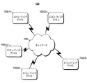
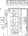
図1に、例示的なネットワーク100を示す。ネットワーク100の設定では、複数(x)のコンピューティングデバイス102(1)、102(2)、...、102(x)がネットワーク106に結合されている。ネットワーク106は、様々な従来型のネットワークプロトコル(公衆および/またはプロプラエタリプロトコルを含む)を採用した、様々な従来型のネットワークトポロジおよびタイプ(配線および/または無線ネットワークを含む)のいずれかを表すものとする。ネットワーク106には、例えばローカルエリアネットワーク(LAN)、ワイドエリアネットワーク(WAN)、インターネットの一部、その他を含めることができる。ネットワーク100の設定は、例えばデータセンタ(例えばインターネットデータセンタ(IDC))、オフィスまたはビジネス設定、家庭設定、教育または研究施設、小売または販売設定、データストレージ設定などを含めた、幅広い設定のいずれかを表す。
FIG. 1 illustrates an
コンピューティングデバイス102は、デスクトップPC(personal computer)、ワークステーション、メインフレームコンピュータ、サーバコンピュータ、インターネット装置、ゲーム用コンソール、ハンドヘルドコンピュータ、携帯電話、パーソナルディジタルアシスタント(PDA)などを含めた、様々な従来型のコンピューティングデバイスのいずれかとすることができる。1つまたは複数のデバイス102は、同じタイプのデバイスでもよく、あるいは異なるタイプのデバイスでもよい。さらに、複数のデバイスが同じタイプのデバイスである場合でも、複数のデバイスはなお、異なる形で構成することもできる(例えば、2つのデバイス102はサーバコンピュータだが、異なるプロセッサ、異なる容量のランダムアクセスメモリ(RAM)、異なるサイズのハードディスクドライブなど、異なるハードウェア構成を有することもできる)。
1つまたは複数のコンピューティングデバイス102は、ネットワーク100の設定に追加した後で再構成することもできる。例えば、特定のコンピューティングデバイス102が、ある期間にわたって(例えば分、時間、日、月などの単位で)動作して1つの機能を実施し、次いで管理者が、異なる機能が望ましいと決定することもできる(例えば、サーバコンピュータからワークステーションコンピュータへの変更、ウェブサーバからローカルなファイルサーバへの変更)。
One or
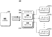
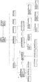
図2は、システム定義モデルを使用する例示的なアーキテクチャ200を示すブロック図である。SDMは、システムのライフサイクル全体にわたって使用されるように設計される。システムは、協働して共通の機能を達成することのできる関連するソフトウェアおよび/またはハードウェアリソースのセットである。このようなシステムの一例はアプリケーションであり、アプリケーションは、コンピューティングデバイスによって稼動または実行されて様々な機能を実施することのできる命令のセットを指す。アプリケーションの例としては、ゲームなどの娯楽アプリケーション、ワードプロセッサなどの生産性アプリケーション、電子百科辞典などの参照アプリケーション、ウェブサービスや財務分析に使用できる分散アプリケーションなどが挙げられる。このようなシステムの別の例は、アプリケーション(または別の環境)を展開することのできる環境である。環境は、アプリケーション(または別の環境)の展開先であるソフトウェアおよび/またはハードウェアリソースを指す。このような環境は、後でより詳細に論じるようにレイヤ化することができる。
FIG. 2 is a block diagram illustrating an
システムのライフサイクルは通常、3つの主要フェーズ(ステージとも言う)を含む。すなわち、設計または開発フェーズと、それに続く展開またはインストールフェーズと、それに続く運用または管理フェーズである。このモデルは、システムライフサイクルの3つのフェーズすべてに適用されるので、システムライフサイクルの様々なフェーズのための統合ポイントと見なすことができ、3つのフェーズのそれぞれを容易にする。さらに、このモデルを使用することにより、これらのフェーズの間で知識を移すことができる。知識は、システムの管理に関する知識(例えば、設計開発チームが将来のバージョンのためまたは現バージョンの性能改善のためにシステムを修正できるように、設計開発チームにフィードバックされる知識)や、システムの構造、展開要件、動作挙動の知識や、デスクトップからデータセンタへの動作環境の知識や、エンドユーザによって観察されたサービスレベルの知識などである。 The life cycle of a system typically includes three major phases (also called stages). That is, a design or development phase, followed by a deployment or installation phase, and a subsequent operation or management phase. Since this model applies to all three phases of the system life cycle, it can be viewed as an integration point for the various phases of the system life cycle, facilitating each of the three phases. In addition, using this model, knowledge can be transferred between these phases. Knowledge may include knowledge of system management (eg, feedback given to the design and development team so that the design and development team can modify the system for future versions or to improve the performance of the current version) and the structure of the system. , Deployment requirements, knowledge of operating behavior, knowledge of the operating environment from the desktop to the data center, and knowledge of the service level observed by the end user.
一般に、設計フェーズの間、SDMに影響を与える開発ツールを使用して、通信ソフトウェアおよびハードウェアコンポーネントからなるシステムを定義する。システム定義は、必要なリソース、構成、動作特徴、ポリシーなどを含めて、分散システムを展開および運用するのに必要なすべての情報を含む。展開フェーズの間、システム定義を使用してシステムを自動的に展開し、必要なソフトウェアおよびハードウェア(例えばサーバ、ストレージ、およびネットワーク)リソースを動的に割り振り、構成する。同じシステム定義を、異なるホスト環境および異なる規模への展開に使用することができる。管理フェーズの間、オペレーティングシステム中のSDMサービスが、システムを管理するためのシステムレベルのビューを提供する。これにより、新しい管理ツールが、リソース割振り、構成管理、アップグレード、およびプロセス自動化をシステムの視点から推進することができる。 Generally, during the design phase, a development tool that affects the SDM is used to define a system consisting of communication software and hardware components. The system definition contains all the information needed to deploy and operate a distributed system, including necessary resources, configurations, operating characteristics, policies, and the like. During the deployment phase, the system is automatically deployed using system definitions, and the required software and hardware (eg, server, storage, and network) resources are dynamically allocated and configured. The same system definition can be used for deployment to different host environments and different sizes. During the management phase, an SDM service in the operating system provides a system-level view for managing the system. This allows new management tools to drive resource allocation, configuration management, upgrades, and process automation from a system perspective.
アーキテクチャ200は、SDM定義モデルと、SDM定義モデル内の機能動作を定義するスキーマとを採用する。定義モデルは、異なる様々な種類のデータ構造を含み、これらは「定義」と総称される。SDMの機能は、アプリケーションプログラムインタフェース(API)など、1つまたは複数のプラットフォームサービスを介して開示(expose)される。
システムの設計フェーズの間、開発システム202が、SDM文書204のようなシステム定義を含む文書を生成する。開発システム202は、米国ワシントン州レドモンドのMicrosoft(登録商標)Corporationから入手可能なVisual Studio(登録商標)開発システムなど、様々な開発システムのいずれかとすることができる。SDM文書204は、システムの展開および管理に関係するすべての情報(本明細書では知識とも言う)を定義する。システムを展開または管理する際に必要なまたは使用されるどんな知識も、SDM文書204に含まれる。本明細書では知識を単一の文書として述べるが、別法として複数の文書に分散させて維持してもよいことを理解されたい。
During the design phase of the system, the
SDM文書204は、システムが展開および/または実行されることになる環境が満たさなければならない1つまたは複数のシステム制約(要件とも言う)を含む。環境自体も、SDM文書を使用して記述される。このような環境は、単一のコンピューティングデバイスとすることもでき、あるいは、コンピューティングデバイスの集合(例えばデータセンタ)、アプリケーションホストの集合などとすることもできる。異なるシステムを異なる環境にインストールすることができる。例えば、データセンタが50台のコンピューティングデバイスを含む場合に、あるシステムをこれらのコンピューティングデバイスのうちの5台に展開し、別のシステムをこれらのコンピューティングデバイスのうちの35台に展開することができる。これらの要件は、次のような様々な形をとる可能性がある。すなわち、システムの展開先であるコンピューティングデバイスに関するハードウェア要件(例えば最低プロセッサ速度、最低メモリ容量、最低ハードドライブ空き容量、利用可能なネットワーク帯域幅の最低量、利用可能な特定のセキュリティ機構など)や、システムの展開先であるコンピューティングデバイスに関するソフトウェア要件(例えば特定のオペレーティングシステム、共にインストールしなければならない1つまたは複数の他のアプリケーション、特定のシステムおよび/またはオペレーティングシステムをどのように構成するかに関する指定、使用される特定タイプのセキュリティまたは暗号化など)や、システムの展開先であるコンピューティングデバイスに関するその他の要件(例えば利用可能なセキュリティ鍵、施行しなければならないデータセンタポリシー、使用される認証、環境トポロジなど)等である。 SDM document 204 includes one or more system constraints (also referred to as requirements) that must be met by the environment in which the system will be deployed and / or executed. The environment itself is also described using an SDM document. Such an environment may be a single computing device, or a collection of computing devices (eg, a data center), a collection of application hosts, and so on. Different systems can be installed in different environments. For example, if a data center includes 50 computing devices, deploy one system to five of these computing devices and deploy another system to 35 of these computing devices. be able to. These requirements can take various forms: That is, the hardware requirements (eg, minimum processor speed, minimum memory, minimum hard drive space, minimum available network bandwidth, specific security mechanisms available, etc.) for the computing device on which the system is deployed. And the software requirements for the computing device on which the system is deployed (eg, a particular operating system, one or more other applications that must be installed with it, how to configure the particular system and / or operating system) Specifications, specific types of security or encryption used, and other requirements for the computing device on which the system is deployed (eg, available security keys, security Data center policies that must be, authentication used is an environment topology, etc.) and the like.
要件は別な方向に向かう可能性もある。すなわち、環境が、インストールされるシステムの構成に対して制約または要件を有する可能性もある(例えば環境の基準またはポリシーを実施するため)。これらは、環境のオペレータによって生み出される「明示的な」要件とすることができ、システムが有さなければならない特定の設定または構成や、システムが提供またはサポートしなければならない特定の機能や、システムがサポートしなければならない特定のセキュリティ機構などである。これらはまた、環境の特定の構成によって生じる「暗黙的な」要件とすることもできる。例えば、環境中のホストコンピューティングデバイスが特定タイプのファイルシステムを使用している場合に、このファイルシステムを使用して実施することができないアクションがある場合がある(別のファイルシステムを使用すればこれらのアクションを実施することができるにもかかわらず)。 Requirements may be heading in another direction. That is, the environment may have restrictions or requirements on the configuration of the system to be installed (eg, to enforce environmental standards or policies). These can be "explicit" requirements created by the environment's operators, specific settings or configurations that the system must have, specific features that the system must provide or support, Such as the specific security mechanisms that must be supported. These can also be "implicit" requirements caused by a particular configuration of the environment. For example, if the host computing device in the environment uses a particular type of file system, there may be actions that cannot be performed using this file system (if another file system is used, Although these actions can be performed).
システムの設計および開発フェーズの間、SDM文書204を使用して、1つまたは複数の特定の環境についてシステムを妥当性検査することができる。これは両方向の妥当性検査である。すなわち、システムを環境について妥当性検査し、環境をシステムについて妥当性検査する。環境をシステムについて妥当性検査することは、SDM文書204中で識別される要件を環境と比較して、すべての要件が環境によって満たされるかどうかを決定することによって行うことができる。システムを環境について妥当性検査することは、SDM文書中で環境に関して識別される要件をシステムと比較して、すべての要件がシステムによって満たされるかどうかを判定することによって行うことができる。すべての要件が環境およびシステムによって満たされる場合、設計者または開発者には、システムをこの環境で展開できること、およびシステムがこの環境で実行されることがわかる。しかし、すべての要件が環境および/またはシステムによって満たされない場合は、設計者または開発者には、任意選択で、満たされなかった要件が通知され、それにより、システムをこの環境で展開して実行するためにどんな変更をSDM文書204に(かつそれに対応してシステムに)および/または環境に加えるべきかが通知される。 During the system design and development phase, the SDM document 204 can be used to validate the system for one or more specific environments. This is a two-way validation. That is, the system is validated for the environment, and the environment is validated for the system. Validating the environment for the system may be performed by comparing the requirements identified in the SDM document 204 to the environment and determining whether all requirements are met by the environment. Validating the system for the environment can be done by comparing the requirements identified for the environment in the SDM document with the system and determining whether all requirements are met by the system. If all requirements are met by the environment and the system, the designer or developer will know that the system can be deployed in this environment and that the system will run in this environment. However, if not all requirements are met by the environment and / or the system, the designer or developer is optionally notified of the missing requirements, thereby deploying and running the system in this environment. Inform the SDM document 204 (and correspondingly to the system) and / or to the environment to make changes.
SDM文書204に含まれるシステム展開に関する知識は、システムをどのように1つまたは複数の環境で展開するかを記述する。SDM文書204は、コントローラ206に利用可能とされ、コントローラ206は、展開モジュール208および管理モジュール210を備える。ある実施形態では、SDM文書204、ならびにシステムをインストールするのに必要なシステムファイルすべて(例えばバイナリ、データ、ライブラリなど)は、SDU(システム定義ユニット)と呼ぶ単一のコンテナ(例えば単一のファイル)に共にパッケージされる。コントローラ206は、図1のコンピューティングデバイス102の1つまたは複数とすることができる。例えば、図1の単一のデバイス102が特定のデータセンタ用のコントローラであってもよく、あるいは、コントローラの任務は複数のデバイス102に分散されてもよい。
The system deployment knowledge contained in the SDM document 204 describes how to deploy the system in one or more environments. The SDM document 204 is made available to a
展開モジュール208は、システムを環境中に展開するのに使用されるサービスを含む。図2では、システムが展開される環境は、1つまたは複数のターゲットデバイス212である(またはこれらのデバイス上に展開されている)。システムはまた、コントローラ206に展開することもできる。展開モジュール208のこれらのサービスには、1つまたは複数のシステムを環境中にインストールまたは展開するために呼び出すことのできる1つまたは複数の関数が含まれる。
SDM文書204には、異なる環境で展開するための異なる知識を含めることができる。この展開知識は、環境中で行う必要のある任意の変更(例えば、システムレジストリ、作成する必要のあるフォルダ、ディレクトリ、またはファイル、特定の値に設定する必要のある、コンピューティングデバイスのその他の設定パラメータまたは構成パラメータなどの変更)、ならびに、環境中でどのファイル(例えばプログラムファイルおよび/またはデータファイル)をコンピューティングデバイスにコピーする必要があるか、またこれらのファイルに対して実施する必要のある任意の操作(例えば圧縮解除および/または暗号化解除が必要なファイルもある)を記述する。多くの実装形態では、SDM文書204中の展開知識は、例えば、システムのための通常のセットアッププログラムまたはインストールプログラム中に現在みられるような情報に類似する情報を含む。 The SDM document 204 can include different knowledge for deployment in different environments. This deployment knowledge is based on any changes that need to be made in the environment (eg, system registry, folders, directories, or files that need to be created, other settings on the computing device that need to be set to specific values, etc.). Changes to parameters or configuration parameters, etc.), and what files (eg, program files and / or data files) in the environment need to be copied to the computing device and need to be performed on these files Describe any operations (eg, some files need to be decompressed and / or decrypted). In many implementations, the deployment knowledge in the SDM document 204 includes information similar to information currently found in, for example, a normal setup or installation program for the system.
展開プロセスの間、コントローラ206は、展開に関与するソフトウェアおよびハードウェアリソースの、ならびにこれらの関係の、記録または記憶を生成する。この記録または記憶は、後で管理フェーズの間にコントローラ206が使用することができる。
During the deployment process, the
管理モジュール210は、システムが環境にインストールされた後でシステムを管理するのに使用されるサービスを含む。サービス管理モジュール210のこれらのサービスには、環境中でシステムを管理するために呼び出すことのできる1つまたは複数の関数が含まれる。SDM文書204に含まれるシステム管理に関する知識は、システムをどのように1つまたは複数の環境で管理するかを記述する。
SDM文書204には、システムを異なる環境で管理するための異なる知識を含めることができる。管理知識には、システムの管理または運用で使用される任意の知識が含まれる。管理には、例えば、構成(および任意選択で後の再構成)、パッチおよびアップグレード、保守作業(例えばバックアップ)、ヘルス監視または性能監視などが含まれる。 The SDM document 204 can include different knowledge for managing the system in different environments. Management knowledge includes any knowledge used in managing or operating the system. Management includes, for example, configuration (and optionally later reconfiguration), patches and upgrades, maintenance operations (eg, backup), health monitoring or performance monitoring, and the like.
展開されたシステムに対する変更は、管理モジュール210を介して行う。管理モジュール210のサービスには、環境中に展開された1つまたは複数のシステムに変更を加えるために呼び出すことのできる1つまたは複数の関数が含まれる。管理モジュール210を介してこれらの変更を行うことにより、いくつかの利点を実現することができる。このような利点の1つは、加えられた変更の記録をコントローラ206が維持できることである。コントローラ206は、システムについてのSDM文書204のコピーを維持し、システムに加えられたどんな変更もSDM文書204に記録することができる。あるいはコントローラ206は、システムに加えられた変更に関する別個の記録を維持してもよい。
Changes to the deployed system are made via the
コントローラ206によって維持されるこの変更記録は、システムおよび/または環境に関する問題を解決するときや、ハードウェア障害によりシステムを再インストールしなければならないとき(システムを再インストールして障害時と同じパラメータ/設定で稼動するよう元に戻せるようにする)などに、後続の操作を単純化することができる。コントローラ206によってこのような変更が行われるようにすることにより、またコントローラ206が記録を維持するようにすることにより、いくらかの人為的ミスを環境からなくすことができる(例えば、変更を行う管理者が変更を帳面に記録することになっているのにそうするのを忘れた場合、この変更の記録はないことになる。この問題は、コントローラ206に記録を維持させることによって解決する)。
This change log maintained by the
さらに、コントローラ206を介してシステムに変更を加えることにより、またコントローラ206を介してシステムを展開することにより、コントローラ206は、環境と、環境中に展開されるシステムと、これらの間の対話とに関する知識のリポジトリとして働くことができる。環境および/または環境中に展開されるシステムに関する知識は、コントローラ206から容易に得ることができる。この知識を使用して、中央のコントローラ206に記憶されている状態を環境中の被制御デバイスが反映していることを妥当性検査することにより、被制御環境の一貫性を保証することができる。
In addition, by making changes to the system via the
状況によっては、コントローラ206を介さずに、システムおよび/または環境に変更が加えられる場合もあることに留意されたい。例えば、コンピューティングデバイスが誤ってオフにされたり、作動しなくなったりすることがある。これらの状況では、このような変更をコントローラ206中に反映させるよう試みる。これらの変更は、自動的にコントローラ206中に反映させることもでき(例えば、デバイス障害を検出して、このような障害を管理モジュール210のサービスを使用してコントローラ206に通知するシステムを稼動させることができる)、あるいは手動でコントローラ206中に反映させることもできる(例えば、管理者が管理モジュール210のサービスを使用して、このような変更をコントローラ206に通知することができる)。あるいは、加えられた変更を元に戻し、システムおよび/または環境の一部を、コントローラ206によって記録された所望のシステム状態と再び一致させることもできる。
Note that in some circumstances, changes may be made to the system and / or environment without going through the
したがって、SDM文書204は、「生きた」文書と見なすことができる。すなわち、環境の変化および/またはシステムの変化に基づいて、システムのライフサイクルを通して継続的に変化することができる。 Thus, the SDM document 204 can be considered a "live" document. That is, it can change continuously throughout the life cycle of the system based on environmental changes and / or system changes.
システム定義モデル(SDM)
システム定義モデル(SDM)は、システムの定義を生み出すのに使用されるモデル化技法である。システムは、協働して共通の機能を達成する関連するソフトウェアおよび/またはハードウェアリソースのセットである。例示的なシステムには、多層LOB(line−of−business)アプリケーション、ウェブサービス、電子商取引サイト、および企業データセンタが含まれる。SDMは、アプリケーション構築者、ネットワーク構築者、データセンタ構築者、またはその他の開発者が分散コンピュータアプリケーションおよびデータセンタを抽象方式で設計するためのツールおよびコンテキストを提供する。SDMは、物理的なコンピュータリソースおよびソフトウェアによって最終的に実現されることになるシステムの機能単位を表す要素のセットを定義する。SDMはまた、システムを管理することになるオペレータまたはその他の個人に関係する要素も定義する。さらにSDMは、開発、展開、および運用に関係するデータも取り込む。SDM要素には、コンポーネントによって表される機能動作をどのように指定すべきかを指示するスキーマが関連する。
System definition model (SDM)
A system definition model (SDM) is a modeling technique used to generate a definition of a system. A system is a set of related software and / or hardware resources that work together to achieve a common function. Exemplary systems include multilayer LOB (line-of-business) applications, web services, e-commerce sites, and enterprise data centers. SDM provides tools and contexts for application builders, network builders, data center builders, or other developers to design distributed computer applications and data centers in an abstract manner. The SDM defines a set of elements that represent the functional units of the system that will ultimately be implemented by physical computer resources and software. The SDM also defines the operators or other individuals related elements that will manage the system. SDM also captures data related to development, deployment, and operation. Associated with the SDM element is a schema that dictates how the functional behavior represented by the component should be specified.
システムは、リソース、エンドポイント、関係、およびサブシステムで構成される。これらの各項目の定義が、SDM文書中で宣言される。SDM文書は、システム、リソース、エンドポイント、および関係についての1つまたは複数の定義を含むXML(Extensible Markup Language)文書である。リソースは、ハードウェアリソースまたはソフトウェアリソースとすることができる。エンドポイントは、システムを越えた通信を表す。関係は、システム、リソース、エンドポイントの関連を定義する。サブシステムは、完全なシステムとして扱うことができ、通常はより大きいシステムの一部である。 The system is composed of resources, endpoints, relationships, and subsystems. The definition of each of these items is declared in the SDM document. An SDM document is an Extensible Markup Language (XML) document that contains one or more definitions for systems, resources, endpoints, and relationships. Resources can be hardware resources or software resources. Endpoints represent communications across systems. Relationships define the relationships between systems, resources, and endpoints. Subsystems can be treated as complete systems and are usually part of a larger system.
システム定義は、動的システムの基本構造を取り込む。これは、他のすべての情報がその上に追加される骨格と見なすことができる。この構造は一般に、開発プロセスの間に設計者および開発者によって指定され、通常は頻繁に変更されることはない。構造の他に、SDMは、展開情報、インストールプロセス、構成やイベントや計測のためのスキーマ、自動化タスク、ヘルスモデル、運用ポリシーなども含むことができる。分散システムの存続期間を通して、運用スタッフ、ベンダ、および/または管理システムがその他の情報を追加することができる。 The system definition captures the basic structure of the dynamic system. This can be viewed as a skeleton on which all other information is added. This structure is generally specified by the designer and developer during the development process and usually does not change frequently. In addition to the structure, the SDM can also include deployment information, installation processes, schemas for configuration, events and measurements, automation tasks, health models, operational policies, and the like. Throughout the life of the distributed system, operations staff, vendors, and / or management systems can add other information.
SDMスキーマ設計仕様
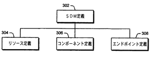
SDMは、分散システム(例えばモデル化システム)中のコンポーネントの構成、対話、および変更の記述(description)をサポートするように設計される。「定義(definition)」が、システム中に存在するエンティティを記述し、「関係(relationship)」が、様々なエンティティ間のリンクを識別する。定義および関係はさらに、SDMに関連するセマンティック情報を取り込むように定義される。図3に示すように、SDM定義302は、リソース定義304、コンポーネント定義306、エンドポイント定義308という3つのサブ定義を含む。
SDM Schema Design Specification SDM is designed to support the description of the configuration, interaction, and modification of components in a distributed system (eg, a modeling system). “Definition” describes the entities that exist in the system, and “relationship” identifies the links between the various entities. Definitions and relationships are further defined to capture semantic information related to the SDM. As shown in FIG. 3, the
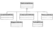
図4に示すように、SDM関係402は、包含関係404、委任関係406、接続関係408、ホスティング(hosting)関係410、参照関係412という5つのサブ関係を含む。接続関係408は、「通信関係」と呼ばれる場合もある。定義および関係に関するこれ以上の詳細は後で提供する。
As shown in FIG. 4, the
SDMは「抽象定義」を含む。これは、システムの各部分の共通範疇化と、幅広いアプリケーションのためのツールサポートと、設計時の定義チェックのための基盤とを提供する。抽象定義のセットは、サービス設計のための包括的な基盤を提供する。「具象定義」が、実際のアプリケーション設計またはデータセンタ設計の各部分を表す。具象定義の生成は、抽象定義を選択し、具象定義のメンバとそのプロパティの設定値とを定義する実装を提供することによって行う。分散アプリケーションは、これらの具象定義の集合を使用して生成する。 SDM includes "abstract definitions". It provides a common categorization of parts of the system, tool support for a wide range of applications, and a basis for design-time definition checking. The set of abstract definitions provides a comprehensive foundation for service design. The "concrete definition" represents each part of the actual application design or data center design. The generation of a concrete definition is performed by selecting an abstract definition and providing an implementation that defines the members of the concrete definition and the setting values of their properties. A distributed application is generated using a set of these concrete definitions.
SDMは「制約」も含む。制約は、関係のインスタンスが参与することのできる許容される関係のセットに基づく制限をモデル化する。制約は、関係に関与するオブジェクトの構成に応じた要件を記述する際に有用である。例えば、制約を使用して、通信プロトコルの両端の参与者が互換性のあるセキュリティ設定を使用しているかどうかを判定することができる。 SDM also includes "constraints". Constraints model constraints based on the set of allowed relationships that an instance of the relationship can participate in. Constraints are useful in describing requirements according to the composition of the objects involved in the relationship. For example, constraints can be used to determine whether participants at both ends of the communication protocol are using compatible security settings.
定義および/またはリソースの一部として、フローを識別することができる。このフローを使用して、オペレータ設定をシステム、サブシステム、またはこのような設定を利用する他のコンポーネントに伝搬させることによって、ランタイム時のアプリケーション挙動を制御する。 As part of the definition and / or resources, the flow can be identified. This flow is used to control application behavior at runtime by propagating operator settings to the system, subsystems, or other components that utilize such settings.
抽象定義および抽象関係
抽象定義は、設計時にアプリケーション構成をチェックしてからランタイム時にアプリケーションを展開および管理する構成単位を定義する。これらの構成単位は、モデル化システム中に存在するエンティティを表す。例えば抽象定義は、ファイルおよびディレクトリ、ウェブサーバ内部の構成、またはSQL(Structured Query Language)サーバ内部のデータベースをモデル化することができる。
Abstract Definitions and Abstract Relationships Abstract definitions define the compositional units that check the application configuration at design time and then deploy and manage the application at runtime. These building blocks represent entities that exist in the modeling system. For example, the abstract definition can model files and directories, a configuration inside a web server, or a database inside a Structured Query Language (SQL) server.
抽象関係は、抽象定義間で行うことのできる対話をモデル化する。関係は、バイナリおよび有向であり、関係の発現に参与するインスタンスの定義を識別する。関係は、エンティティを相互に関連付ける方法を提供し、それにより、エンティティ間の包含、構築、通信のリンクをモデル化することを可能にする。 Abstract relationships model the interactions that can take place between abstract definitions. Relationships are binary and directed and identify the definition of the instances that participate in the expression of the relationship. Relationships provide a way to correlate entities and thereby model the containment, construction, and communication links between entities.
定義が制約を使用して、定義の参与する関係を制約する。さらに、関係が制約を使用して、リンクすることのできる定義を制約する。これらの制約は、関係への参与者の定義および設定をターゲットにすることができる。 The definition uses constraints to constrain the relationships in which the definition participates. In addition, relationships use constraints to constrain the definitions that can be linked. These constraints can target the definition and setting of participants in the relationship.
抽象定義空間は、コンポーネント、エンドポイント、リソースという3つのカテゴリに分けられる。抽象コンポーネント定義は、アプリケーションの自己完結型かつ独立展開可能な部分を記述する。これらの定義は、プロセスおよびマシンの境界を横断することのできる明確に定義された通信チャネルを介して対話するアプリケーション部分を表す。抽象エンドポイント定義は、コンポーネントが開示することのできる通信エンドポイントを記述する。これらの抽象エンドポイント定義は、設計時にシステム接続性を検証するためおよびランタイム時に接続を可能にするために、システムが意識しているすべての形の通信をモデル化することができる。抽象リソース定義は、コンポーネント内に含まれる挙動(behavior)を記述する。リソース定義は、他のリソース定義への強力な従属性を有することができる。これらの従属性には、特定のインストール順序を必要とすることや、様々な通信機構を介したランタイム対話を開始することを含めることができる。 The abstract definition space is divided into three categories: components, endpoints, and resources. An abstract component definition describes a self-contained and independently deployable part of an application. These definitions represent the parts of the application that interact via well-defined communication channels that can cross process and machine boundaries. An abstract endpoint definition describes a communication endpoint that a component can disclose. These abstract endpoint definitions can model all forms of communication that the system is aware of, to verify system connectivity at design time and to enable connectivity at runtime. The abstract resource definition describes the behavior (behavior) included in the component. Resource definitions can have strong dependencies on other resource definitions. These dependencies may include requiring a particular installation order and initiating runtime interactions via various communication mechanisms.
抽象定義は、設定を開示する(expose)能力を備える。一実施形態では、これらの設定は、名前と値の単純な対であり、XMLスキーマを使用して設定の定義を定義する。設定は動的としても静的としてもよい。静的設定は、展開プロセスの間にわたり設定される。動的設定は、展開後に変更することができる。実行中のシステムに設定値を適用することを担うコードは、SDMランタイム中でホストされる。 Abstract definitions provide the ability to expose settings. In one embodiment, these settings are simple name-value pairs and use an XML schema to define the definition of the settings. The settings may be dynamic or static. Static settings are set during the deployment process. Dynamic settings can be changed after deployment. The code responsible for applying the settings to the running system is hosted in the SDM runtime.
SDMモデルは、抽象定義を越えた継承をサポートする。派生した定義は、その親によって開示されたプロパティを拡張することができ、その親のプロパティに関する値を設定することができる。派生した定義は、その親を参与者として識別する関係に参与することができる。 The SDM model supports inheritance over abstract definitions. A derived definition can extend the properties disclosed by its parent and set values for properties of its parent. The derived definition can participate in a relationship that identifies its parent as a participant.
前述のように、関係は、通信(または接続)、包含、委任、ホスティング、参照という5つのカテゴリに分けられる。通信関係は、抽象エンドポイント定義間の可能性ある通信対話を取り込む。通信関係があることは、識別された定義のエンドポイントを開示しているコンポーネントが通信することが可能かもしれないことを示す。実際のリンク確立は、エンドポイントおよびエンドポイントの開示(exposure)に対する制約を受ける。 As described above, relationships are divided into five categories: communication (or connection), containment, delegation, hosting, and reference. Communication relationships capture possible communication interactions between abstract endpoint definitions. Having a communication relationship indicates that the component disclosing the endpoint of the identified definition may be able to communicate. The actual link establishment is constrained by the endpoint and the exposure of the endpoint.
包含関係は、抽象定義が他の抽象定義のメンバを含むことができることを記述する。より具体的には、2つの抽象定義AとBの間の包含関係では、Aを実装する具象定義が、Bを実装する定義のメンバを含むことができる。包含関係は、開発者がアプリケーションを構築するときに生じる自然なネスト構造をモデル化する。別の定義のメンバを含めることにより、親は、含まれる定義の存続期間および可視性を制御することができる。ランタイム空間中のすべての定義インスタンスは、他の定義インスタンスのメンバとして存在し、完全に接続されたインスタンスセットを形成する。したがって、包含関係のセットは、ランタイム空間で生じる許容される包含パターンを記述する。 Containment describes that an abstract definition can include members of other abstract definitions. More specifically, in the containment relationship between two abstract definitions A and B, a concrete definition that implements A can include members of the definition that implements B. Containment models the natural nesting that occurs when developers build applications. By including members of another definition, the parent can control the lifetime and visibility of the included definition. All definition instances in the runtime space exist as members of other definition instances, forming a fully connected instance set. Thus, a set of containment relationships describes the allowed containment patterns that occur in the runtime space.
委任関係は、含まれるメンバを選択的に開示する。例えば委任は、コンポーネント定義からのエンドポイントメンバを開示することができる。内側のコンポーネントからエンドポイントを委任することにより、外側のコンポーネントは、特定のプロトコルを使用して、プロトコルの奥にある実装を開示することなく通信する能力を呈する。 The delegation relationship selectively discloses the members involved. For example, the delegation can disclose the endpoint members from the component definition. By delegating the endpoint from the inner component, the outer component presents the ability to communicate using a particular protocol without disclosing the underlying implementation of the protocol.
ホスティング関係および参照関係は、従属関係の2つの形を表す。ホスティング関係は、特定ホスト上に定義のインスタンスをどのように生成するかに関する知識を取り込むのに使用する。ホスティング関係により、開発者は、特定ホストの動作から独立した方式で自分自身の定義を生成することができる。この関係ではまた、ゲスト定義を書き換えずに単一の定義を複数のホストタイプ上に展開することができる。ホスティング関係は、具象定義のインスタンスが生成される前に存在する抽象定義間の主要な従属性を記述する。各インスタンスは、ホスティング関係にゲストとして参与し、それによりホスティング関係は、完全に接続されたツリーをインスタンス空間にわたって形成する。参照関係は、パラメータフローおよび構築順序付けに使用される追加の従属性を取り込む。 Hosting relationships and reference relationships represent two forms of subordination. Hosting relationships are used to capture knowledge about how to create an instance of a definition on a particular host. Hosting relationships allow developers to generate their own definitions in a manner independent of the operation of a particular host. This relationship also allows a single definition to be deployed on multiple host types without rewriting the guest definition. Hosting relationships describe the key dependencies between abstract definitions that exist before an instance of a concrete definition is created. Each instance participates as a guest in the hosting relationship, so that the hosting relationship forms a fully connected tree across the instance space. Reference relationships capture additional dependencies used for parameter flow and construction ordering.
具象定義および具象関係
抽象定義から具象定義を構築する。抽象関係から具象関係を構築する。抽象定義と抽象関係の組合せは、ターゲットシステムをモデル化するためのスキーマを定義する。具象定義は、抽象定義空間のサブセットを使用して、1つまたは複数の抽象定義の再使用可能な構成を生み出す。抽象定義空間は、データベースに関するスキーマに例えることができる。この類比では、具象定義空間は、データベース中の行のセットのための再使用可能テンプレートを表す。データベース中の行をスキーマの制約(例えば外部キーなど)に対して妥当性検査するのと同じようにして、具象定義を抽象定義空間に対して妥当性検査する。開発者は、抽象定義の知識から具象定義の知識を推論することができる。したがって、抽象定義に関連するツールが、抽象定義から派生する多くの実装と共に動作することができる。例えば、抽象ウェブサービスについて知っているツールが、開発者からの追加の情報を必要とせずに、データセンタ中に展開された任意のウェブサービスと共に動作することができる。
The concrete definition is constructed from the concrete definition and the concrete relation abstract definition. Construct concrete relationships from abstract relationships. The combination of the abstract definition and the abstract relation defines a schema for modeling the target system. Concrete definitions use a subset of the abstract definition space to create a reusable composition of one or more abstract definitions. An abstract definition space can be likened to a schema for a database. In this analogy, the concrete definition space represents a reusable template for a set of rows in a database. The concrete definition is validated against the abstract definition space in the same way that rows in the database are validated against schema constraints (for example, foreign keys). The developer can infer the knowledge of the concrete definition from the knowledge of the abstract definition. Thus, the tools associated with the abstract definition can work with many implementations that derive from the abstract definition. For example, tools that know about abstract web services can work with any web service deployed in a data center without requiring additional information from developers.
各具象定義は、特定の抽象定義に対する実装を提供し、実装は、設定スキーマに対する拡張と、設定に関する値と、定義メンバおよび関係メンバに関する宣言と、定義が参与することのできる関係に対する制約とを含む。具象定義の挙動は、抽象定義の定義に従う。具体的には、抽象コンポーネント定義がコンポーネント定義になり、抽象エンドポイント定義がエンドポイント定義になり、抽象リソース定義がリソース定義になる。 Each concrete definition provides an implementation for a particular abstract definition, which implements extensions to the configuration schema, values for the configuration, declarations for the definition and relationship members, and constraints on the relationships that the definition can participate in. Including. The behavior of the concrete definition follows the definition of the abstract definition. Specifically, the abstract component definition becomes the component definition, the abstract endpoint definition becomes the endpoint definition, and the abstract resource definition becomes the resource definition.
各具象関係は、特定の抽象関係に対する実装を提供し、実装は、設定スキーマおよび設定値と、同じ関係カテゴリ(ホスティング、包含、通信など)のネストされたメンバと、関係に参与することのできる定義に対する制約とを含む。 Each concrete relationship provides an implementation for a particular abstract relationship that can participate in relationships with configuration schemas and values and nested members of the same relationship category (hosting, containment, communication, etc.). Including constraints on definitions.
具象ホスティング関係は、ある具象定義のメンバを別の具象定義上にマッピングすることのできるホスティング関係のセットを定義する。例えば、具象ホスティング関係は、ウェブアプリケーションとそれが展開されることになるIIS(Internet information service)(商標)ホストとの間のバインドを識別することができる。特定の定義に対して複数の具象ホスティング関係が存在することができ、これにより開発者は、特定のトポロジに対して複数の展開(deployment)を定義することができる。 Concrete hosting relationships define a set of hosting relationships that allow members of one concrete definition to be mapped onto another concrete definition. For example, a concrete hosting relationship may identify a binding between a web application and an Internet Information Service (IIS) (TM) host on which it will be deployed. There can be multiple concrete hosting relationships for a particular definition, which allows a developer to define multiple deployments for a particular topology.
具象定義は、他の具象または抽象定義のメンバを宣言することができる。これらを「定義メンバ」と呼ぶ。この場合、これらの定義メンバは、定義メンバ間の関係を定義する「関係メンバ」から参照される。定義メンバは、特定の定義のインスタンスへの参照を含む。設定フローが、定義に関する値を提供することができ、あるいは、定義を生成するときに使用される構築パラメータを制約することができる。定義メンバを宣言するとき、ユーザ(例えば開発者)は、定義メンバが、外側のコンポーネントが生成されるのと同時に生成されるか(「値セマンティクス」と呼ばれる)、あるいは後で行われる新しい明示的動作によって生成されるか(「参照セマンティクス」と呼ばれる)を決定することができる。 Concrete definitions can declare members of other concrete or abstract definitions. These are called "definition members". In this case, these definition members are referred to from “relation members” that define the relationship between the definition members. A definition member contains a reference to an instance of a particular definition. The configuration flow can provide values for the definition, or can constrain the build parameters used when generating the definition. When declaring a definition member, the user (e.g., the developer) must either create the definition member at the same time that the outer component is created (called "value semantics"), or create a new explicit Can be determined by the action (called "reference semantics").
関係メンバは、定義メンバが生成されたときにそれらが参与することになる関係を定義する。定義メンバが具象定義に含まれる場合は、包含関係メンバを、定義メンバと外側の定義に対するこの参照との間で宣言する。定義メンバが委任される場合は、委任関係メンバを、定義メンバとネストされる定義メンバとの間で定義する。通信関係メンバは、定義メンバ上のエンドポイント間で宣言することができ、従属関係メンバ(参照およびホスティング)は、定義メンバまたはネストされる定義メンバ間で宣言することができる。 Relationship members define the relationships that will be involved when the definition members are created. If the definition member is included in the concrete definition, declare the containment member between the definition member and this reference to the outer definition. If the definition members are delegated, define the delegation relationship members between the definition members and the nested definition members. Communication relationship members can be declared between endpoints on definition members, and dependency relationship members (reference and hosting) can be declared between definition members or nested definition members.
関係制約は、特定の定義が参与を望む関係のセットを限定する。関係制約は、特定の関係に対する制約、および関係の他方の端の参与者に対する制約を識別する。 Relationship constraints limit the set of relationships that a particular definition wants to participate. Relationship constraints identify constraints on a particular relationship and constraints on participants at the other end of the relationship.
インスタンス空間
SDMランタイムに記憶されているインスタンス空間は、モデル化システムの現在状態を識別する。SDMランタイムは、生成されたインスタンスと、これらのインスタンス間の関係との記録を含む。各インスタンスにはバージョン履歴が関連し、バージョン履歴は、各バージョンを変更要求にリンクする。変更要求は、新しいインスタンスを生成するプロセスである。変更要求は、既存のインスタンスの特定メンバに関連する定義および関係に対する、生成、更新、削除要求のセットを定義する。ルートは特別なケースとして扱われる。
Instance Space The instance space stored in the SDM runtime identifies the current state of the modeling system. The SDM runtime contains a record of the instances created and the relationships between these instances. Associated with each instance is a version history, which links each version to a change request. A change request is the process of creating a new instance. A change request defines a set of create, update, and delete requests for definitions and relationships associated with a particular member of an existing instance. Routes are treated as a special case.
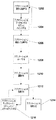
変更要求は、ランタイムによって展開され、1つまたは複数の制約に対して検証されてから構築される。展開プロセスでは、含んでいる定義の構築要求の一部として暗黙的に構築される定義インスタンスおよび関係インスタンスを識別する。展開プロセスの一部として、設定フローをすべての関係にわたって評価する。検証ステップでは、必要な関係がすべて存在すること、および関係が必要な制約を満たすことをチェックする。最後に構築プロセスでは、各インスタンスの展開、更新、または削除にわたる適切な順序付けを判定する。次いで構築プロセスでは、適切なアクションが実施されるように、各インスタンスを正しいシーケンスでインスタンスマネージャに渡す。 Change requests are deployed by the runtime and validated against one or more constraints before being built. The deployment process identifies definition instances and relationship instances that are implicitly constructed as part of the containing definition construction request. Evaluate the configuration flow across all relationships as part of the deployment process. The verification step checks that all required relationships exist and that the relationships satisfy the required constraints. Finally, the build process determines the proper ordering over deployment, update, or deletion of each instance. The build process then passes each instance in the correct sequence to the instance manager so that the appropriate actions are performed.
データセンタは、複数のソフトウェアコンポーネントを使用して生み出すことができる。複数のソフトウェアコンポーネント間で、1つまたは複数の接続を構成する。これらのソフトウェアコンポーネントのいくつかは、アプリケーションレイヤに関するホストとして機能することができる。ホストレイヤ中の例示的なコンポーネント定義としては、IIS(商標)、SQL、AD、EXCHANGE、DNS(Domain Name System)、BizTalk(商標)が挙げられる。 A data center can be created using multiple software components. Configure one or more connections between multiple software components. Some of these software components can function as hosts for the application layer. Exemplary component definitions in the host layer include IIS ™, SQL, AD, EXCHANGE, DNS (Domain Name System), BizTalk ™.
ネットワーク/OS(operating system)/ストレージレイヤは、データセンタネットワークおよびプラットフォームの構築をサポートする。このレイヤはまた、ネットワークセキュリティモデルの構成、オペレーティングシステムプラットフォームの構成、および、1つまたは複数の記憶デバイスとオペレーティングシステムプラットフォームとの関連付けもサポートする。ネットワーク/OS/ストレージレイヤ中の例示的なコンポーネント定義としては、VLAN、Windows(登録商標)、Filter、Storageが挙げられる。 The network / OS (operating system) / storage layer supports the construction of data center networks and platforms. This layer also supports the configuration of the network security model, the configuration of the operating system platform, and the association of one or more storage devices with the operating system platform. Exemplary component definitions in the network / OS / storage layer include VLAN, Windows (R), Filter, and Storage.
ハードウェアレイヤは、データセンタに存在するシステムの定義、およびこれらのシステム間に存在する物理接続を識別する。特定のコンポーネントに必要な関係を満たすために、このコンポーネントを、マッチする機能を有するホストコンポーネントにバインドする。このプロセスを「論理配置(logical placement)」と呼ぶ。展開時、ゲストコンポーネントのインスタンスを、ホストコンポーネントのインスタンス上に配置する。このプロセスを「物理配置(physical placement)」と呼ぶ。 The hardware layer identifies the definitions of the systems that exist in the data center and the physical connections that exist between these systems. Bind this component to a host component with matching functionality to satisfy the required relationship for a particular component. This process is referred to as "logical placement." During deployment, place guest component instances on host component instances. This process is called "physical placement".
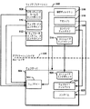
図5に、ウェブアプリケーション502をウェブサーバホスト504にマッピングする例を示す。破線506で識別される境界が、アプリケーションレイヤをホストレイヤから分離している。ウェブアプリケーション502は、リモーティングサービスエンドポイント508、ウェブサービスエンドポイント510、およびウェブユーザインタフェースエンドポイント512を含み、これらはすべて、ウェブサーバ504中のウェブサイト522にマッピングする。さらに、ウェブアプリケーション502中の仮想ディレクトリ516が、ウェブサイト522にマッピングする。ウェブアプリケーション502はコンシューマエンドポイント514も含み、コンシューマエンドポイント514は、ウェブサーバ504中のコンシューマエンドポイント524にマッピングする。ウェブアプリケーション502のアセンブリ部分518が、ウェブサービス504のランタイム部分528にマッピングする。ウェブアプリケーション502中のコンテンツディレクトリ520が、ウェブサーバ504中のウェブルートディレクトリ526にマッピングする。
FIG. 5 shows an example of mapping the
SDMモデルには、分散システムに対する変更を管理するプロセスが関連する。分散システムに対する変更は、1つまたは複数の処理ステップを経た変更要求によって進められ、その後、要求の中の動作が配信され、ターゲットシステムに対して実行される。 The SDM model involves a process that manages changes to the distributed system. Changes to the distributed system are driven by a change request through one or more processing steps, after which the actions in the request are delivered and executed on the target system.
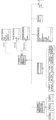
図6に、SDMランタイムを使用する例示的なアーキテクチャ600を示す。アーキテクチャ600は、図2のアーキテクチャ200の一例であり、SDMランタイム610と、後で「例示的なSDM実装形態」の章で論じるSDMの例示的な実装形態とを使用する。SDMランタイム610は、SDMファイルを受領して妥当性検査し、SDU(システム定義ユニット。1つまたは複数のSDMファイルおよびそれらに関係するファイルのパッケージ)をロードし、SDM変更要求を生成して実行し、SDMベースのシステムをターゲット環境に展開するための、コンポーネントおよびプロセスのセットを含む。このランタイム機能により、SDMを使用して記述されたシステムを定義および妥当性検査し、コンピューティングデバイスのセットに展開し、管理することができる。
FIG. 6 shows an
SDMは、後で「例示的なSDM実装形態」の章でより詳細に論じるが、分散システム(モデル化システム)中のコンポーネントの構成、対話、および変更の記述(description)をサポートするように設計される。SDMは、オブジェクト関係(relational)モデルに基づく。「定義」が、システム中に存在するエンティティを記述し、「関係(relationship)」が、様々なエンティティ間のリンクを識別する。定義および関係はさらに、SDMに関連するセマンティクス情報を取り込むように定義される。具体的には、定義はコンポーネント、エンドポイント、リソースに分けられる。関係は、接続(通信とも言う)、包含、ホスティング、委任、参照に分けられる。定義および関係に関するこれ以上の詳細は後で提供する。 The SDM is designed to support the description of the composition, interaction, and modification of components in a distributed system (modeling system), which will be discussed in more detail in the "Example SDM Implementation" section below. Is done. SDM is based on an object relational model. "Definitions" describe the entities that exist in the system, and "relationships" identify the links between the various entities. Definitions and relationships are further defined to capture semantic information related to the SDM. Specifically, definitions are divided into components, endpoints, and resources. Relationships can be broken down into connections (also called communications), inclusion, hosting, delegation, and referrals. More details on the definitions and relationships will be provided later.
SDMは「抽象定義」を含む。これは、システムの各部分の共通範疇化と、幅広いシステムのためのツールサポートと、設計時の定義チェックのための基盤とを提供する。抽象定義のセットは、サービス設計のための包括的な基盤を提供する。「具象定義」が、実際のシステム設計またはデータセンタ設計の各部分を表す。具象定義の生成は、抽象定義を選択し、具象定義のメンバとそのプロパティの設定値とを定義する実装を提供することによって行う。分散アプリケーションは、これらの具象定義の集合を使用して生成する。 SDM includes "abstract definitions". This provides a common categorization of parts of the system, tool support for a wide range of systems, and a basis for design-time definition checking. The set of abstract definitions provides a comprehensive foundation for service design. The "concrete definition" represents each part of the actual system design or data center design. The generation of a concrete definition is performed by selecting an abstract definition and providing an implementation that defines the members of the concrete definition and the setting values of their properties. A distributed application is generated using a set of these concrete definitions.
SDMは「制約(constraint)」も含む。制約は、関係のインスタンスが参与することのできる許容される関係のセットに基づく制限をモデル化する。制約は、関係に関与するオブジェクトの構成に応じた要件を記述する際に有用である。例えば、制約を使用して、通信プロトコルの両端の参与者が互換性のあるセキュリティ設定を使用しているかどうかを判定することができる。 SDM also includes "constraint". Constraints model constraints based on the set of allowed relationships that an instance of the relationship can participate in. Constraints are useful in describing requirements according to the composition of the objects involved in the relationship. For example, constraints can be used to determine whether participants at both ends of the communication protocol are using compatible security settings.
ターゲットシステムに対する変更を実施するために、SDMは、「変更要求」またはCRと呼ばれる、必要とされる変更の宣言記述を使用する。SDMは、「SDM実行モデル」の一部として変更要求を展開(expand)、妥当性検査、および実行するのに使用されるプロセスを定義する。 To implement changes to the target system, the SDM uses a declarative description of the required change, called a "change request" or CR. The SDM defines the process used to expand, validate, and execute change requests as part of the "SDM execution model".
「インスタンス空間」は、管理されるアプリケーションの所望状態と現在状態の両方を取り込む。インスタンス空間中の変更は、追跡され、その変更を開始した変更要求に関連付けられる。インスタンス空間は、SDMランタイム内に記憶され、モデル化システムの現在状態を反映する。ランタイムは、生成されたインスタンスと、これらのインスタンス間の関係との完全な記録を含む。各インスタンスにはバージョン履歴が関連し、バージョン履歴中では、各バージョンが変更要求にリンクされている。新しいインスタンスを生成するプロセスは、変更要求によって開始される。変更要求は、既存のインスタンスの特定メンバに関連する定義および関係に対する、生成、更新、削除要求のセットを定義する。 The "instance space" captures both the desired state and the current state of the managed application. Changes in the instance space are tracked and associated with the change request that initiated the change. The instance space is stored in the SDM runtime and reflects the current state of the modeling system. The runtime contains a complete record of the instances created and the relationships between these instances. Each instance is associated with a version history in which each version is linked to a change request. The process of creating a new instance is started by a change request. A change request defines a set of create, update, and delete requests for definitions and relationships associated with a particular member of an existing instance.
以下は、図6のコンポーネントがどのように協働するかについての簡単な機能上の解説である。オペレータまたは管理者が、データセンタのトポロジなど、アプリケーションを展開(deploy)できる環境を記述することができる。オペレータまたは管理者は、環境を記述するSDMファイルを作成するが、このファイルは、「論理インフラストラクチャ」(LIM)602、あるいはデータセンタ記述またはデータセンタモデルと呼ばれる。このSDMファイルは、米国ワシントン州レドモンドのMicrosoft(登録商標)Corporationから入手可能なVisual Studio(登録商標)開発システムなど、様々な開発システムのいずれかを使用して生成することができる。 The following is a brief functional description of how the components of FIG. 6 work together. Describe the environment where operators or administrators can deploy applications, such as data center topologies. The operator or administrator creates an SDM file that describes the environment, which is referred to as the "logical infrastructure" (LIM) 602, or data center description or data center model. The SDM file can be generated using any of a variety of development systems, such as the Visual Studio® development system available from Microsoft® Corporation of Redmond, Washington, USA.
さらに、アプリケーション開発者は、Visual Studio(登録商標)開発システムなどの様々な開発システムのいずれかを使用して、自分のアプリケーションを設計および開発することができる。開発者は、アプリケーションのコンポーネントと、これらのコンポーネントがどのように相互に関係するかを定義するので、アプリケーション記述をデータセンタ記述602に対して妥当性検査することができる。これを「設計時妥当性検査」とも呼ぶ。
In addition, application developers can design and develop their applications using any of a variety of development systems, such as the Visual Studio® development system. The developer can validate the application description against the
アプリケーションが完成すると、開発者は記述をSDMに保存し、アプリケーションがSDU604として展開されるようにアプリケーションのパッケージングを要求する。SDUは、アプリケーションSDMと、アプリケーションをインストールするのに使用されるアプリケーションバイナリおよびその他の参照ファイルとを含む。 When the application is completed, the developer saves the description in the SDM and requests packaging of the application so that the application is deployed as SDU 604. The SDU contains the application SDM and the application binaries and other reference files used to install the application.
LIM602およびSDU604は、展開(deployment)に向けて、コントローラデバイス620の展開ツール606に供給される。展開ツール606は、オペレータが所望のSDU604をロードできるようにするためのユーザインタフェース(UI)を備える。展開ツール606は、CR生成モジュール630と協働して、SDU604に関連するアプリケーションを、SDU604内のSDM中の情報に従ってインストールする。さらに、SDU604からのSDM定義およびインスタンスが、SDMランタイム610のSDM記憶域(store)608にポピュレートされる。SDUは、SDMランタイム610中でSDU管理モジュール640によって管理され、SDU管理モジュール640は、ランタイム610の他のコンポーネントおよびターゲット622がSDUの適切な部分を利用できるようにする。
オペレータはまた、展開中のアプリケーションの展開先であるターゲット622(例えばターゲットコンピューティングデバイス)に対してオペレータがどんなアクションを取りたいかを指定することができる。オペレータは、展開ファイルを介してこれを行うことができ、この展開ファイルは、本明細書では変更要求(CR)とも呼ばれる。CRは、1つまたは複数のエンジン612、614、616、618を通して実行される。一般に、CR展開エンジン612は、CRを展開して、関連するすべてのコンポーネントならびにそれらの接続およびアクションを識別する。値フローエンジン614は、コンポーネントに関する値(接続ストリングなど)をフローする。制約チェックエンジン616は、環境とアプリケーションとの間の制約をチェックする。アクション順序付けエンジン618は、CRに関する必要なすべてのアクションの順序を指定する。
The operator can also specify what action the operator wants to take on a target 622 (eg, a target computing device) to which the application being deployed is to be deployed. The operator can do this via a deployment file, which is also referred to herein as a change request (CR). CR is performed through one or
システムに対する変更(アプリケーションの展開を含む)、またはモデルの妥当性検査を開始するために、オペレータまたはプロセスは、CRをサブミット(submit)する。CRは、オペレータがランタイム610中のインスタンスを介して実施したいアクションのセットを含む。これらのアクションは、例えば生成アクション、更新アクション、および/または削除アクションとすることができる。
To initiate changes to the system (including application deployment) or model validation, the operator or process submits the CR. The CR contains the set of actions that the operator wants to perform via the instance in
ユーザまたはオペレータによって開始される変更要求に加えて、展開/自動生成の変更要求があるものとすることもでき、これは、後でより詳細に論じる展開プロセスの一部として生成される。変更要求は、そのソースにかかわらず、完全に展開されチェックされた後で、ターゲットインスタンスの発見、インストール、アンインストール、変更などのアクションをターゲット622に送ることによって実行される。 In addition to user or operator initiated change requests, there may be deployment / auto-generated change requests, which are generated as part of the deployment process discussed in more detail below. The change request, regardless of its source, is performed by sending actions such as discovering, installing, uninstalling, and modifying the target instance to the target 622 after it has been fully deployed and checked.
CRは、グループとして完了または失敗する原子アクションセットとして扱われる。これにより例えば、制約チェックエンジン616は、妥当性をテストするときにすべてのアクションを考慮することができる。 CRs are treated as atomic action sets that complete or fail as a group. This allows, for example, the constraint checking engine 616 to consider all actions when testing for validity.
設計時妥当性検査では、CRは、SDMコンパイラ628によって生成され、SDMファイル中の各SDMコンポーネントの1つまたは最小限を含むことになる。この、インスタンス生成コマンドのCRは、CR展開エンジン612、値フローエンジン614、および制約チェックエンジン616の中をフローする。この3つのフェーズで見つかったエラーは、ユーザが使用している開発システムを介してユーザに返される。
For design-time validation, the CR will be generated by the SDM compiler 628 and will include one or a minimum of each SDM component in the SDM file. The CR of the instance generation command flows through the
展開時は、オペレータは、展開ツール606によって提示されるUI(user interface)でCRを生成する。CRは、SDMランタイム610中のすべてのエンジン612、614、616、618の中をフローし、適切なアクションおよび情報がCR実行モジュール632から適切なターゲット622に送られ、ターゲット622で要求が実行される(例えばアプリケーションがインストールされる)。特定のインストールの場合の適切なターゲット622は、通常、アプリケーションがインストールされることになるターゲットである。
At the time of deployment, the operator generates a CR using a UI (user interface) presented by the
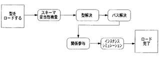
CRの処理を開始する際、定義解決フェーズで、CR生成モジュール630は、変更要求の中で参照されるすべての定義およびメンバを解決する。変更要求は、これらがすでにランタイム610によってロードされていると見なす。これらが存在しない場合は、CR生成モジュール630はロード/コンパイルアクションを開始する。CR生成モジュール630はパス解決フェーズも実施し、変更要求内の、既存のインスタンスおよび生成アクションによって定義されたインスタンスへの参照を解決する。
To begin processing the CR, in a definition resolution phase, the
CR展開エンジン612によって実施される展開は、所与の変更要求について、この要求を実行するのに必要な残りのすべてのアクションをポピュレートするプロセスである。一般にこれらのアクションは、定義インスタンスおよび関係インスタンスに対する構築(construction)アクションおよび破壊(destruction)アクションである。オペレータは任意選択で、インスタンスを構築または破壊するのに必要なすべてのアクションに関する詳細を提供することもでき、あるいはこのプロセスの一部は自動化することもできる。例えばオペレータは、メンバ(例えばbyReferenceメンバ)に対するアクションを識別することにより、オペレータが望む変更に関するキー情報を提供する。すると、ネストされたメンバ(例えばbyReferenceメンバおよびbyValueメンバ)と関係に対して、アクションの残りが埋められる。別の例として、自動化された展開は、外部リソースマネージャを参照することもでき、外部リソースマネージャは、利用可能なリソースを有するデバイスを選択することや、それが必要とするデータに近いアプリケーションを突き止めることなどに基づいて、展開決定を行うことができる。
The deployment performed by the
CR展開エンジン612は、「自動記述(writing)」も実施する。自動記述の間、CR展開エンジン612は、SDM中で指定されているコンポーネントおよび複合コンポーネントのスケール不変のグループ化を分析し、コンポーネントが要求のレベルにスケールされたときにコンポーネントがどのようにグループ化され相互接続されるべきかを判定する。
The
CR展開エンジン612は、値(value)メンバ展開、参照(reference)メンバ展開、および関係展開も実施する。
The
値メンバ展開は、すべての非参照定義メンバを識別することを指す。これらのメンバのカーディナリティ(cardinality)が示され、必要なパラメータはすべてわかるので、各メンバごとに、親の生成中であるメンバについては生成要求が変更要求に追加される。変更要求が破壊動作を含む場合は、それらに含まれるすべてのインスタンスについて破壊動作が追加される。 Value member expansion refers to identifying all non-reference defined members. Since the cardinality of these members is indicated and all necessary parameters are known, for each member, a creation request is added to the change request for the member whose parent is being created. If the change request includes a destruction operation, the destruction operation is added for all instances included in the change request.
参照メンバ展開は、参照メンバを指す(非参照定義メンバとは反対に)。参照メンバのカーディナリティはしばしば未定義であり、参照メンバは、インスタンスが構築されるための値を必要とする展開時設定を有する可能性がある。したがって、参照メンバ(例えばbyReferenceメンバ)を展開するプロセスは、インスタンスに関する情報として、ランタイムが提供できるよりも多くの情報を必要とする可能性がある。 Reference member expansion refers to reference members (as opposed to non-reference definition members). The cardinality of the reference member is often undefined, and the reference member may have an unfolding setting that requires a value for the instance to be constructed. Thus, the process of expanding a reference member (eg, a byReference member) may require more information about the instance than the runtime can provide.
参照メンバ展開には、発見と呼ばれるプロセスが関係するが、これは、すでに展開されたインスタンスを見つけるのに使用されるプロセスである。発見は、通常は環境のオペレータによって開始されるアクションである。例えばインストール要求の間、CR展開エンジン612は、インスタンスがすでに存在するかどうかを判定し、存在する場合は何が存在するかを判定し、存在しない場合はそれを生成する。コントローラ620上のインスタンスマネージャ(IM)634が、ターゲットデバイス622上のインスタンスマネージャ626と通信して、発見プロセスを開始する。発見プロセスは、インスタンスに関するデータをターゲットデバイス622からコントローラ620に返す。
Reference member expansion involves a process called discovery, which is the process used to find already expanded instances. Discovery is an action usually initiated by the environment operator. For example, during an installation request, the
発見のプロセスは、構築または更新アクションの一部として参照定義メンバをポピュレートする。通常、発見をサポートするオブジェクトマネージャ(発見を実施もするインスタンスマネージャ)に関する参照メンバだけが、このプロセスに参与する。 The discovery process populates the reference definition members as part of the build or update action. Typically, only the reference members for the object managers that support discovery (the instance managers that also perform discovery) participate in this process.
新しいインスタンスが発見されたときは、インスタンス特有のキー値を使用して、このインスタンスがまだSDMデータベース中に存在しないことをチェックする。新しいインスタンスであることがわかれば、発見されているメンバの定義に従ってインスタンスを分類する。インスタンスがメンバにマッチしない場合、または曖昧なマッチがある場合は、メンバ参照は空白のままにされ、インスタンスはオフラインおよび不完全としてマークされる。 When a new instance is discovered, use the instance-specific key value to check that this instance does not yet exist in the SDM database. If a new instance is found, the instance is classified according to the definition of the discovered member. If the instance does not match the member, or if there is an ambiguous match, the member reference is left blank and the instance is marked offline and incomplete.
関係展開は、構築されることになる定義インスタンスがすべてわかった後で、定義インスタンスを共にバインドする関係インスタンスを生成することを指す。定義インスタンスの破壊中である場合は、定義インスタンスを参照するすべての関係インスタンスを削除する。 Relationship expansion refers to creating a relationship instance that binds the definition instances together after all the definition instances to be built are known. If the definition instance is being destroyed, delete all relationship instances that reference the definition instance.
関係を生成するには、メンバ空間を使用して、インスタンス間に存在すべき関係の構成を識別する。定義メンバが1よりも大きいカーディナリティを有する場合、関係のトポロジは基底関係定義から推論する。例えば、通信関係の場合は「自動記述」を実施することができ、ホスト関係の場合は、ホスティング関係に関連するアルゴリズムに基づいてホストを選択する。 To create a relationship, the member space is used to identify the composition of the relationship that must exist between instances. If the defining member has a cardinality greater than one, the topology of the relationship is inferred from the base relationship definition. For example, in the case of a communication relationship, “automatic description” can be performed, and in the case of a host relationship, a host is selected based on an algorithm related to the hosting relationship.
フローステージの間、値フローエンジン614は、すべての関係インスタンスにわたってフローを評価する。値フローエンジン614は、改変されたパラメータフローの影響を受けたインスタンスについて、変更要求に更新要求を追加することができる。値フローエンジン614は、変更要求の結果として設定が更新されたインスタンスのセットを判定することにより、フローを評価する。これらのそれぞれにつき、修正された設定に依存する送出設定フローがあればそれを評価し、変更されたインスタンスのセットにターゲットノードを追加する。このプロセスは、そのセットが空になるまで、またはそのセットが循環を含むまで継続する。
During the flow stage, the
フローステージの後、重複検出のプロセスを実施する。重複検出は、図6に示すエンジンのうちの1つ(例えば値フローエンジン614や制約チェックエンジン616)によって実施することもでき、あるいは、図6に示していない別のエンジンによって実施することもできる(例えば重複検出エンジンをSDMランタイム610に含めることができる)。重複検出のプロセスは、展開されたインスタンスを、SDMデータ記憶域中にすでに存在するインスタンスと照合する。例えばこのプロセスは、別のアプリケーションが共有ファイルをインストールしたかどうかを検出する。すでに存在するインスタンスが検出されたときは、存在するインスタンスのバージョンに応じて、いくつかのアクションの1つを実施することができる。すなわち、インストールを失敗にすること、インスタンスを参照カウントすること、インスタンスをアップグレードすること、またはインストールを並行して実施することができる。
After the flow stage, the process of duplicate detection is performed. Duplicate detection may be performed by one of the engines shown in FIG. 6 (eg,
制約チェックエンジン616は、制約評価フェーズを実施する。このフェーズでは、モデル中のすべての制約をチェックして、変更要求が処理された後でもこれらがまだ有効となるかどうかを調べる。 The constraint check engine 616 performs a constraint evaluation phase. In this phase, all constraints in the model are checked to see if they are still valid after the change request has been processed.
制約チェックエンジン616が制約評価フェーズを終了した後には、完全なアクションリストが利用可能である。したがって、アクション順序付けエンジン618は、コンポーネント間の関係を使用して、有効な変更順序付けを判定することができる。この判定は、様々なアルゴリズムのいずれかを使用して行うことができる。 After the constraint check engine 616 has completed the constraint evaluation phase, the complete action list is available. Accordingly, the action ordering engine 618 can use the relationships between the components to determine a valid change ordering. This determination can be made using any of a variety of algorithms.
アクション順序付けエンジン618が順序付けを終了すると、マシン特有の順序付けされたアクションセットのサブセットを配信することによって展開を実施することができる。アクションがマシンによって順序付けされグループ化された後、アクションと、インスタンス情報を含むランタイムのSDM記憶域608の必要部分のコピーとが、ターゲットコンピューティングデバイス622に送られる。SDMは、一時的にターゲットデバイスの記憶キャッシュ638に記憶することができる。
Once the action sequencing engine 618 has finished sequencing, deployment can be performed by delivering a subset of the machine-specific ordered set of actions. After the actions are ordered and grouped by machine, the actions and a copy of the required portion of the runtime's SDM storage 608, including instance information, are sent to the target computing device 622. The SDM may be temporarily stored in the target device's
ターゲットコンピューティングデバイスは、SDMランタイム610と通信するSDMランタイムのターゲット部分636を備える。ターゲットコンピューティングデバイス622はエージェントも備えており、このエージェントは、実行エンジン624を備え、ターゲットデバイス上の適切なインスタンスマネージャ(IM)626と通信して、生成、更新、削除アクションなどの変更をターゲットに対して行うことができる。各アクションは、原子呼出しとしてインスタンスマネージャ626に送られる。インスタンスマネージャ626は、ステータスメッセージを返し、アクションによってはデータも返す(例えば発見の場合)。すべてのアクションがターゲット622上で完了すると、ターゲットのエージェントは、エラーがあればエラーと、ステータスとをコントローラ620に返す。次いでコントローラ620は、この情報を使用してランタイムのSDM記憶域608を更新する。
The target computing device includes a
上で論じたように、変更は、影響を受ける関係に基づいて変更要求を配信可能部分に分解することによって行われる。すべての部分が完了すると(あるいは1つまたは複数の部分が失敗した後で)、ランタイム610中で結果が照合され、概要がオペレータに返される。失敗の場合は、すべてのアクションを「ロールバック」することができ、システムを変更開始前の状態に戻すことができる。
As discussed above, changes are made by breaking the change request into deliverables based on the affected relationships. When all parts are complete (or after one or more parts have failed), the results are matched in
いくつかの実施形態では、上で論じた設計時妥当性検査の間、SDMコンパイラ628がSDMファイルを受け取り、テストCRを生成し、SDMランタイムの展開エンジン、値フローエンジン、および制約チェックエンジンを通してテストCRを実行し、エラーがあればエラーを開発システムに返す。このプロセスにより、展開に向けたSDM妥当性検査が、設計時の間に開発者にもたらされる。 In some embodiments, during the design-time validation discussed above, the SDM compiler 628 receives the SDM file, generates a test CR, and tests it through the SDM runtime's deployment engine, value flow engine, and constraint checking engine. Executes the CR and returns any errors to the development system. This process provides developers with SDM validation for deployment during design time.
SDMランタイム610および/またはコントローラ620への公開インタフェースは、オブジェクトモデル(API)ライブラリを介する。このライブラリは、マネージドコードオブジェクトモデルであり、以下の項目の実施を可能にする。
・ランタイム内でSDMを管理する。−SDMファイルをランタイムにロードすることができる。SDMは不変であり、一度に1つロードされる(すなわち、ファイルの一部だけ(例えばSDMファイルからの個々の定義、クラス、またはマッピングの1つ1つ)ではなく、1つのSDMファイルをロードすることができる)。SDMをランタイムから削除することができ、ランタイム内のSDMについてのXML文書を作成することができる。
・ランタイムによって知られるSDUを管理する。
・SDM定義を管理する。−SDM要素を見つけて検討する(ランタイムにロードされたSDMから)。新しいSDMをオーサリングするために提供される公開APIはない(すなわちこれは、SDMの不変要素に対する読出し専用オブジェクトモデルである)。これは、SDM、SDU、識別、バージョン、クラス、定義、バインド/マッピング、およびバージョニングポリシーを含む。
・SDMインスタンスを管理する。−コンポーネント、エンドポイント、リソース、および関係のインスタンスを見つけて検討する。インスタンス空間では、各インスタンスを、GUID、安定パス、またはアレイベースのパスで識別することができる。パスはストリングであり、相対的とすることができる。相対パスを含めたこれらの識別子により、変更要求文書などの文書中でインスタンスを見つけて参照することができる。
・インスタンスを操作する。−生成、トポロジ変更、アップグレード、設定変更、削除を含めて、SDMインスタンスに対して変更を行う。インスタンス変更は変更要求の範囲内で行われ、変更要求は、エラーまたは制約違反があれば要求が完全に失敗するように、更新の原子単位を提供する。インスタンス要求はまた、インスタンスが一時的にホストへのバインドなしでも存在できるようにする。というのは、要求がコミットされるときはインスタンスはホストを有さなければならないからである。また、単一のコンポーネントのインストールまたは設定に影響を与える多くの操作が行われることを可能にし、単一の更新がコンポーネント上で行われるように、インストールまたは設定の更新がコミットまで延期されるようにする。変更要求のコミット前またはコミット時にSDMモデルチェックを実施し、モデル違反または制約違反があればコミットは失敗する。
・変更要求をロードする。−変更要求は、インスタンス空間操作のセットを提示する文書、例えばXMLファイルである。この文書は、相対パスを利用して、アプリケーションインスタンスを生成または削除するための再使用可能「スクリプト」となることができる。
・変更要求を見つけて検討する。−インストール/更新タスクおよびすべてのエラー情報を得ること、ならびに要求の影響を受けるコンポーネントのインストール/更新を再試行することを含む。
・データベース中の変更要求から変更要求文書を生成する。このような文書はいくぶん移植性がある。
・進行状況、ログ、または更新されたステータスなど、変更要求タスクに関するイベントの通知に申し込む。これらのイベント加入の存続期間は、クライアントライブラリをロードしたプロセスの存続期間によって制限される(すなわちこれらは定期CLRイベントである)。
The public interface to
Manage the SDM in runtime. -SDM files can be loaded at runtime. SDMs are immutable and are loaded one at a time (ie, load one SDM file rather than just a portion of the file (eg, each individual definition, class, or mapping from the SDM file). can do). The SDM can be deleted from the runtime and an XML document can be created for the SDM in the runtime.
Managing SDUs known by the runtime.
-Manage SDM definitions. Find and review SDM elements (from SDM loaded at runtime). There is no public API provided for authoring new SDMs (ie, this is a read-only object model for SDM invariants). This includes SDM, SDU, identification, version, class, definition, binding / mapping, and versioning policy.
-Manage SDM instances. -Find and review instances of components, endpoints, resources and relationships. In the instance space, each instance can be identified by a GUID, stable path, or array-based path. Paths are strings and can be relative. These identifiers, including the relative path, allow instances to be found and referenced in documents such as change request documents.
-Operate the instance. Make changes to the SDM instance, including creation, topology change, upgrade, configuration change, delete. Instance changes are made within the scope of a change request, which provides an atomic unit of update so that any error or constraint violation causes the request to fail altogether. The instance request also allows the instance to exist temporarily without binding to the host. This is because the instance must have a host when the request is committed. It also allows many operations that affect the installation or configuration of a single component to take place, and ensures that installation or configuration updates are deferred until commit so that a single update occurs on the component. To The SDM model check is performed before or at the time of committing the change request, and if there is a model violation or a constraint violation, the commit fails.
Load the change request. The change request is a document that presents a set of instance space operations, for example an XML file. This document can be a reusable "script" for creating or deleting an application instance using a relative path.
• Find and review change requests. -Include install / update tasks and all error information, and retry install / update of components affected by the request.
Generate a change request document from the change request in the database. Such documents are somewhat portable.
Sign up for notifications of events related to change request tasks, such as progress, logs, or updated status. The lifetime of these event subscriptions is limited by the lifetime of the process that loaded the client library (ie, they are periodic CLR events).
SDMランタイムエンジンは、SDMモデル、およびAPIによって表面化された関数に対して、推論を実施する。ライブラリは、SDMをロードする、コンポーネントインスタンスを生成する、SDM全体を得る(SDMエンティティを検討するため)など、かなり粗な呼出しを使用してウェブサービスとしてランタイムエンジンに通信する。このウェブサービスに関する多くのパラメータのフォーマットは、SDMファイルの場合と同じスキーマを有するXMLである。エンジンはまた、許可に対するチェックも実施することができる。 The SDM runtime engine performs inference on SDM models and functions exposed by the API. The library communicates to the runtime engine as a web service using fairly coarse-grained calls, such as loading the SDM, creating component instances, and getting the entire SDM (to consider the SDM entity). The format of many parameters for this web service is XML with the same schema as for SDM files. The engine may also perform a check for permission.
コントローラ620は、インスタンスマネージャ(IM)を利用することができ、IMは、モデル中の任意の定義または関係に関連付けることができる。IMは、以下の役割の1つまたは複数を実施することができる。
・インスタンスの展開をサポートする。
・インスタンスが展開された後のインスタンスの妥当性検査をサポートする(監査)。
・ランタイムを介して展開されたのではない展開済みインスタンスの発見をサポートする。
・設定値のフローをサポートする。
・制約の評価をサポートする。
・変更要求の展開をサポートする。
・APIを介してインスタンスをCLRクラスとしてユーザに提示することをサポートする。
The
-Supports instance deployment.
Supports instance validation after an instance has been deployed (audit).
-Supports discovery of deployed instances that have not been deployed via the runtime.
・ Supports the flow of setting values.
・ Supports constraint evaluation.
-Support the deployment of change requests.
Support for presenting instances as CLR classes to users via APIs.
展開のために、コントローラ620上のインスタンスマネージャ(IM)プラグインがクラスホスト関係に関連付けられるが、このプラグインは、開発システム中で使用される、クラスに関する設計経験を提供し、SDU604中および設定スキーマ中の関連バイナリを作成するプラグインとは別である。インスタンスマネージャは、インスタンスマネージャインタフェースを実装するかまたは抽象クラスから継承するCLRクラスとして(例えばdllアセンブリ中で)SDMランタイム610に供給される。SDMインスタンスマネージャは、インスタンスマネージャ(IM)プラグインとも呼ばれ、以下の機能をコントローラ620に提供する。
・コンポーネントインスタンスをそれらのホストにインストール、アンインストール、または再インストールするためのファイルおよびコマンド(タスク)を生成する。−変更要求の結果、新しいコンポーネントインスタンス、またはコンポーネントインスタンスの削除、またはアンインストールおよび再インストールが必要なコンポーネント変更が生じるとき、インスタンスマネージャは、SDU604中のインスタンス、ホストインスタンス、コンポーネントに関連する定義、これらの定義に関連するバイナリの設定を利用し、手動実行の準備または展開エンジンを介したディスパッチの準備ができたターゲットサーバ上でインストールまたはアンインストールを実施するのに必要なファイルおよびコマンドを作成する。
・コンポーネントインスタンスの設定が変化したとき、またはそのエンドポイントの1つからのビューが変化したとき(例えば通信関係トポロジが変化したせいで、または見えるエンドポイントが設定変更を有するせいで)、コンポーネントインスタンスを更新するためのファイルおよびコマンド(例えばタスク)を生成する。
・コンポーネントインスタンスのエンドポイント上で見えるエンドポイントインスタンスを、コンポーネントインスタンス上の設定にマッピングする。−SDM中で、コンポーネントインスタンスは、何らかの通信関係トポロジの結果として他のエンドポイントインスタンスが見えるエンドポイントインスタンスを有する。他のエンドポイントインスタンスの詳細は、コンポーネントインスタンスがランタイム時にフェッチすることのできる、したがって通常はそれにバインドすることのできる設定にマッピングされる。例えば、ウェブサイトがデータベースクライアントエンドポイントを有し、したがって通信関係はデータベースを使用して確立することができる。正しく確立されたとき、そのデータベースクライアントエンドポイントは、このサーバエンドポイント上の単一のデータベースサーバエンドポイントインスタンスおよび設定を見ることができる。この情報をインスタンスマネージャが使用して、サーバに関する接続ストリングを、クライアントエンドポイントという名前で構成ファイル中に配置する。この結果、コードは単に、データベースに関する接続ストリングをその構成設定から読む。
・コンポーネントインスタンスを監査するためのファイルおよびコマンド(タスク)を生成する。−監査は、存在および正しい設定を確認する。これはホストインスタンス設定にも適用することができる。
・任意のタスクについてステータスを報告する。−IMは、取り込まれた出力の一部または全部を変換し、タスクのステータスを成功、失敗、または不完全として提供し、任意選択で、不完全に関する進行状況(%または最終応答)、失敗に関する詳細(エラーメッセージ)、および任意のステータスに関する人間に読めるログを提供する。インスタンスマネージャに戻ってタスクの出力を解釈することにより、インスタンスマネージャは、診断に十分なログを作成してそれを人間に読めるように維持しなければならないのではなく、そのタスクをログ構造化情報(例えばXML、さらにはSOAP(Simple Object Access Protocol))にすることが自由にできる。
・インスタンスマネージャはまた、ホストとそれらのゲストとの間の制約チェックを実施するコードを提供することもできる。インストーラは、共通の制約言語、例えばXML、XPath、XQueryに基づく言語を使用することができる。
For deployment, an instance manager (IM) plug-in on
Generate files and commands (tasks) to install, uninstall, or reinstall component instances on their hosts. When a change request results in a new component instance or a component change that requires the removal or uninstallation and reinstallation of the component instance, the instance manager may define the instance, host instance, component-related definitions in the SDU 604 Utilizes the binary settings associated with the definition of the to create the files and commands needed to perform an installation or uninstallation on a target server that is ready for manual execution or ready for dispatch via the deployment engine.
A component instance when the configuration of the component instance changes, or when the view from one of its endpoints changes (eg due to a change in the communication relationship topology or the visible endpoint has a configuration change). Generate files and commands (eg, tasks) to update
Map the endpoint instance visible on the component instance endpoint to the settings on the component instance. -In SDM, component instances have endpoint instances in which other endpoint instances are visible as a result of some communication relationship topology. The details of the other endpoint instance are mapped to settings that the component instance can fetch at runtime, and thus can usually bind to it. For example, a website has a database client endpoint, so that communication relationships can be established using a database. When properly established, the database client endpoint can see a single database server endpoint instance and settings on this server endpoint. This information is used by the instance manager to place a connection string for the server in a configuration file, named client endpoint. As a result, the code simply reads the connection string for the database from its configuration settings.
Generate files and commands (tasks) for auditing component instances. -Audits confirm existence and correct settings. This can also be applied to host instance settings.
-Report status for any task. -IM transforms some or all of the captured output and provides the status of the task as successful, failed or incomplete, optionally progress on incomplete (% or final response), on failure Provides details (error messages) and human-readable logs for any status. By returning to the instance manager and interpreting the output of the task, the instance manager does not have to create enough logs for diagnosis and keeps it readable by humans, but (For example, XML, or SOAP (Simple Object Access Protocol)).
-The instance manager can also provide code to perform constraint checks between the host and their guests. The installer can use a common constraint language, for example, a language based on XML, XPath, XQuery.
レイヤ化
SDMモデルは、アプリケーション開発者と、ソフトウェアインフラストラクチャ設計者と、データセンタ構築者との間で関心が分離されるようにする。これらの各グループは、特定のサービスに焦点を合わせ、異なる関心のセットを有する。例えば、開発者は主に、SQL、IIS、CLRなど、開発者が利用するホストの間の構成および接続性に関心を持つ。ホスト構成の設計者は主に、ネットワークトポロジおよびOS構成に関心を持つ。ネットワークトポロジ、OS構成、記憶マッピングを開発する構築者は主に、データセンタに存在するハードウェアに関心を持つ。
The layered SDM model allows for separation of interest between application developers, software infrastructure designers, and data center builders. Each of these groups focuses on a particular service and has a different set of interests. For example, developers are primarily interested in the configuration and connectivity between hosts used by developers, such as SQL, IIS, CLR, and the like. Host configuration designers are primarily interested in network topology and OS configuration. Builders who develop network topologies, OS configurations, and storage mappings are primarily interested in hardware that resides in data centers.
SDMは、システムを横軸と縦軸にわたって機能構成することを可能にする。横軸に沿った構成は、システムおよびサブシステムによって行う。縦軸に沿った構成は、「レイヤ」によって行う。アプリケーション、サービス、ネットワークトポロジ、およびハードウェアは、分散システムにおける役割を果たすが、通常は、独立して定義され、異なるチームまたは組織によって所有されている。レイヤ化は、コンポーネントがホストに対して制約セットを定義することによって、またその逆によって達成される。 SDM allows the system to be functionally configured across the horizontal and vertical axes. Configuration along the horizontal axis is performed by systems and subsystems. The configuration along the vertical axis is performed by “layer”. Applications, services, network topologies, and hardware play a role in distributed systems, but are typically defined independently and owned by different teams or organizations. Layering is achieved by the component defining a set of constraints for the host and vice versa.
この関心の分離をサポートするために、SDMは、レイヤ化の概念を呈示する。レイヤ化は、アプリケーションが依存するサービスをアプリケーションの包含構造の一部として宣言せずに、ホスティング関係を用いてアプリケーションをサービスにバインドすることを指す。レイヤ化により、異なる個人が異なる時に異なるレベルでシステムを開発することができる。 To support this separation of concerns, SDM presents the concept of layering. Layering refers to binding an application to a service using a hosting relationship without declaring the services upon which the application depends as part of the containment structure of the application. Layering allows different individuals to develop systems at different levels at different times.
図7に、例示的なレイヤ化設定を示す。図7には、4つのレイヤすなわちレイヤ702、レイヤ704、レイヤ706、レイヤ708が示されている。4つのレイヤが図7に示されているが、実際のレイヤの数は様々とすることができ、4つよりも多いか少ない可能性もある。さらに、種々のレイヤの内容も、実施形態に応じて様々とすることができる。図7からわかるように、種々のレイヤは他のレイヤの上および/または下に位置する(例えばレイヤ706は、レイヤ704の上にあるがレイヤ708の下にある)。
FIG. 7 shows an exemplary layering setting. FIG. 7 shows four layers, that is, a
レイヤ内の種々のシステムおよびサブシステムが、相互に対話することができ、また、異なるレイヤのシステムおよびサブシステムと対話することができる。例えばレイヤ708中のサブシステム710は、レイヤ708中のサブシステム712、ならびにレイヤ706中のサブシステム714と対話することができる。さらに、各レイヤは、より高い次のレイヤに対する環境と見なすことができる。例えばレイヤ706は、レイヤ708中のシステムおよびサブシステムに対する環境であり、レイヤ704は、レイヤ706中のシステムおよびサブシステムに対する環境である。各レイヤ702、704、706、708は、それ自体の関連するSDM文書を有する。
Various systems and subsystems within a layer can interact with each other and with systems and subsystems at different layers. For example,
種々のレイヤ702、704、706、708は、異なる内容を表すものとすることができる。いくつかの実施形態では、レイヤ702はハードウェアレイヤであり、レイヤ704はネットワークトポロジおよびオペレーティングシステムレイヤであり、レイヤ706はアプリケーションホストレイヤであり、レイヤ708はアプリケーションレイヤである。ハードウェアレイヤは、レイヤ化されたシステムがその上に構築される物理デバイス(例えばコンピューティングデバイス)を表す(例えば図1のデバイス102)。ネットワークトポロジおよびオペレーティングシステムレイヤは、コンピューティングデバイスのネットワークトポロジ(例えば図1のネットワーク100の設定)、ならびにこれらのコンピューティングデバイス上にインストールされるオペレーティングシステムを表す。アプリケーションホストレイヤは、コンピューティングデバイスにインストールされた、他のアプリケーションをホストすることのできるアプリケーションを表す(例えばSQL(Structured Query Language)サーバ、IIS(Internet information service)(商標)など)。アプリケーションレイヤは、コンピューティングデバイスにインストールされた、他のアプリケーションをホストしないアプリケーションを表す(例えばゲームなどの娯楽アプリケーション、ワードプロセッサなどの生産性アプリケーション、電子百科辞典などの参照アプリケーション、ウェブサービスや財務分析に使用できる分散アプリケーションなど)。
The
例示的なSDM実装形態
以下の解説では、SDMの要素を定義するスキーマの一実施形態について述べる。
Exemplary SDM Implementation The following discussion describes one embodiment of a schema that defines the elements of SDM.
1 定義 1 Definition

2 アーキテクチャの概観
システム定義モデル(SDM)は、分散システム(モデル化システム)中のコンポーネントの構成、対話、および変更の記述をサポートするように設計される。
2 Architecture Overview The System Definition Model (SDM) is designed to support the description of the composition, interaction, and change of components in a distributed system (modeling system).
SDMは、オブジェクト関係モデルに基づく。オブジェクトを使用して、システム中に存在するエンティティを記述し、関係を使用して、それらの間のリンクを識別する。SDMではさらに、SDMにとって重要なセマンティクスを取り込むようにオブジェクトおよび関係が改良される。具体的には、オブジェクトはシステム、エンドポイント、リソースに分けられ、関係は通信、包含、ホスティング、委任、参照に分けられる。 SDM is based on an object relationship model. Objects are used to describe the entities that exist in the system, and relationships are used to identify the links between them. In SDM, objects and relationships are further refined to capture semantics important to SDM. Specifically, objects are divided into systems, endpoints, and resources, and relationships are divided into communication, containment, hosting, delegation, and reference.
抽象定義を使用して、システムの各部分の共通範疇化を提供する。これにより、幅広いアプリケーションに対するツールサポートが可能になり、設計時の型チェックのための基盤がもたらされる。抽象定義のセットは、システム設計のための包括的な基盤を提供すると考えられ、これらは時の経過に伴ってゆっくり変化すると考えられる。 Use abstract definitions to provide common categorization of parts of the system. This allows tool support for a wide range of applications and provides the basis for type checking at design time. The set of abstract definitions is considered to provide a comprehensive basis for system design, and these are expected to change slowly over time.
実際のアプリケーションまたはデータセンタの設計の各部分を表す具象オブジェクト定義を構築する。抽象オブジェクト定義を利用して、具象型のメンバとそのプロパティの設定値とを定義する実装を提供する。次いで、これらの定義の集合からシステムを構築する。 Build concrete object definitions that represent parts of the actual application or data center design. Using the abstract object definition, provide an implementation that defines concrete type members and their property setting values. Next, a system is constructed from the set of these definitions.
制約を使用して、インスタンスが参与することのできる許容される関係のセットに対する制限をモデル化する。制約は、関係に関与するオブジェクトの構成に応じたきめ細かい要件を取り込むのに使用する。例えば、制約を使用して、通信プロトコルの両端の参与者が互換性のあるセキュリティ設定を使用していることを妥当性検査することができる。 Use constraints to model the limits on the set of allowed relationships that an instance can participate in. Constraints are used to capture fine-grained requirements depending on the composition of the objects involved in the relationship. For example, constraints can be used to validate that participants at both ends of a communication protocol are using compatible security settings.
ターゲットシステムに対する変更を実施するために、SDMは、変更要求と呼ばれる、必要とされる変更の宣言記述を使用する。SDMは、SDM実行モデルの一部として変更要求を展開、妥当性検査、および実行するのに使用されるプロセスを定義する。 To make changes to the target system, the SDM uses a declarative description of the required change, called a change request. SDM defines the processes used to deploy, validate, and execute change requests as part of the SDM execution model.
インスタンス空間が、管理されるアプリケーションの所望状態と現在状態の両方を取り込む。インスタンス空間中の変更は、追跡され、その変更を開始した変更要求に関連付けられる。 The instance space captures both the desired state and the current state of the managed application. Changes in the instance space are tracked and associated with the change request that initiated the change.
後続のUML(unified modeling language)図は、SDMモデル中のオブジェクト間の広範な対話を取り込むものである。簡単にするために、これらの対話のいくつかは基底型の間で定義されているが、実際の対話は派生型の間に存在し、その結果、より特殊化されている。例えば、通信関係は抽象エンドポイント定義だけを参照する場合がある。 Subsequent unified modeling language (UML) diagrams capture extensive interaction between objects in the SDM model. For simplicity, some of these conversations are defined between base types, but the actual conversations exist between derived types, and as a result are more specialized. For example, a communication relationship may reference only an abstract endpoint definition.
SDM文書は、文書と、文書中の定義に対するマネージャと、他の文書を参照するインポートステートメントと、定義セットとを記述する情報を含む。 An SDM document contains information describing the document, a manager for the definitions in the document, an import statement referring to other documents, and a definition set.
図8に例示的な文書を示す。 FIG. 8 shows an exemplary document.
図9に示すように、すべてのSDM定義は、共通基底定義から派生し、メンバを含むことができる。定義とメンバの間の関係は、後続の図に示すものよりも複雑にすることもできる。 As shown in FIG. 9, all SDM definitions are derived from a common base definition and can include members. The relationships between definitions and members can be more complex than those shown in subsequent figures.
図10に示すように、メンバは、それらが参照する定義の種類によって分けられる。 As shown in FIG. 10, members are classified according to the type of definition to which they refer.
設定宣言は、設定定義を参照する。図11に示すように、設定値および値リストが、設定に関する値を提供する。 The setting declaration refers to the setting definition. As shown in FIG. 11, the setting value and the value list provide values for the setting.
2.1 SDMアプリケーションのライフサイクル
図12に、いくつかの実施形態による例示的なSDMアプリケーションのライフサイクルを示す。
2.1 SDM Application Life Cycle FIG. 12 illustrates an example SDM application life cycle according to some embodiments.
アプリケーションをVisual Studio(登録商標)環境内で設計および実装する(ブロック1202)。開発者は、コンポーネントを実装し、次いでそれらを複合コンポーネント内で結合する。アプリケーションはSDMファイル内に記述する。開発者のアプリケーションが特定のデータセンタ内で展開されることを検証するために、開発者はアプリケーションを、やはりSDMファイル中に記述されたデータセンタ表現にバインドする(ブロック1204)。この表現は、開発者のアプリケーションコンポーネントのホストに関する定義と、開発者のアプリケーションの構成に対する制約とを含む。バインドが失敗した場合は、開発者はアプリケーション設計を修正することができる。 The application is designed and implemented within the Visual Studio® environment (block 1202). Developers implement the components and then combine them in a composite component. The application is described in the SDM file. To verify that the developer's application is deployed in a particular data center, the developer binds the application to a data center representation also described in the SDM file (block 1204). This representation includes a definition of the developer's application component host and constraints on the configuration of the developer's application. If the binding fails, the developer can modify the application design.
開発者が自分のアプリケーションに満足すれば、開発者はアプリケーションに署名して公表することができ、したがって、今やアプリケーションには厳密名(strong name)およびバージョンが関連付けられている(ブロック1206)。アプリケーションの公表された形は、ソフトウェア配信ユニット(SDU)と呼ばれる。オペレータは、開発者からのSDUを採用し、アプリケーションをSDMランタイムにロードする(ブロック1208)。アプリケーションをロードするプロセスの間、オペレータは、アプリケーションをバインドしたいと思うデータセンタのモデルを選択する。オペレータは、アプリケーションを展開することを決定すると、展開時パラメータをアプリケーションに供給し、アプリケーションのスケールを判定する(ブロック1210)。これは変更要求を使用して行う。 If the developer is satisfied with his application, he can sign and publish the application, and thus the application is now associated with a strong name and version (block 1206). The published form of the application is called a software distribution unit (SDU). The operator takes the SDU from the developer and loads the application into the SDM runtime (block 1208). During the process of loading the application, the operator selects the model of the data center to which he wants to bind the application. When the operator decides to deploy the application, it supplies the deployment parameters to the application and determines the scale of the application (block 1210). This is done using change requests.
アプリケーションを展開すると、オペレータはランタイムと対話して、アプリケーションの構成およびアプリケーションの各部分に関する設定を判定することができる(ブロック1212)。ランタイムはまた、アプリケーションの実際の構成が、ランタイム内に記録されている所望の構成とマッチすることを検証することもできる。オペレータは、変更要求をサブミットすることにより、展開したアプリケーションを削除することができる(ブロック1214)。オペレータはまた、サービスパックの削除など、実行中のアプリケーションに加えられた個々の変更をロールバックすることもできる。ブロック1216で、展開されたアプリケーションの一部をウェブフロントエンドなどに対して追加または削除することにより、実行中のアプリケーションの構成を変更することができる。アプリケーションはまた、1つまたは複数のアプリケーションコンポーネントのより新しいバージョンをインストールすることによってアップグレードすることもできる。
Upon deploying the application, the operator can interact with the runtime to determine the configuration of the application and the settings for each portion of the application (block 1212). The runtime may also verify that the actual configuration of the application matches the desired configuration recorded in the runtime. The operator can delete the deployed application by submitting a change request (block 1214). The operator can also roll back individual changes made to the running application, such as deleting a service pack. At
2.2 抽象オブジェクト定義および関係定義
抽象オブジェクト定義は、設計時にアプリケーション構成をチェックしてからランタイム時にアプリケーションを展開および管理するために必要な構成単位を定義する。これらの構成単位は、モデル化システム中に存在するエンティティを表す。例えば、抽象オブジェクト定義を使用して、ファイルおよびディレクトリ、ウェブサーバ内部の構成、またはSQLサーバ内部のデータベースがモデル化される。
2.2 Abstract Object Definitions and Relationship Definitions Abstract object definitions define the building blocks required to check the application configuration at design time and then deploy and manage the application at runtime. These building blocks represent entities that exist in the modeling system. For example, the abstract object definitions are used to model files and directories, configurations inside web servers, or databases inside SQL servers.
抽象関係定義は、抽象オブジェクト定義間で行われる可能性のある対話をモデル化するのに使用する。関係は、バイナリおよび有向であり、関係の発現に参与するインスタンスを定義するオブジェクト定義を識別する。関係は、オブジェクト間の包含、構築、通信のリンクをモデル化できるようにオブジェクトを共に結ぶ方法を提供する。 Abstract relationship definitions are used to model possible interactions between abstract object definitions. Relationships are binary and directed and identify object definitions that define the instances that participate in the manifestation of the relationship. Relationships provide a way to connect objects together so that the containment, construction, and communication links between objects can be modeled.
次いで、オブジェクトが制約を使用して、オブジェクトの参与する関係を制約し、関係が制約を使用して、リンクできるオブジェクトを制約する。これらの制約は、関係への参与者の定義と設定の両方をターゲットにすることができる。これにより制約は、関係への参与者を特定の定義から派生するインスタンスに限定することができ、また、インスタンスが特定の範囲に含まれる設定値を有することを必要とすることができる。 The object then uses the constraint to constrain the participating relationships of the object, and the relationship uses the constraint to constrain the objects that can be linked. These constraints can target both the definition and setting of participants in the relationship. This allows the constraint to limit participants to the relationship to instances that derive from a particular definition and may require that instances have settings that fall within a particular range.
オブジェクト定義は、システム、エンドポイント、リソースという3つのカテゴリに分けられる。 Object definitions fall into three categories: systems, endpoints, and resources.
抽象システム定義は、アプリケーションの自己完結型かつ独立展開可能な部分を記述するのに使用する。これらの定義は、プロセスおよびマシンの境界を横断することのできる明確に定義された通信チャネルを介して対話するアプリケーション部分を表す。 Abstract system definitions are used to describe self-contained and independently deployable parts of an application. These definitions represent the parts of the application that interact via well-defined communication channels that can cross process and machine boundaries.
抽象エンドポイント定義は、システムが開示する(expose)ことのできる通信エンドポイントを記述するのに使用する。これらを使用して、設計時にシステム接続性を検証するためおよびランタイム時に接続を可能にするためにシステムが意識すべきすべての形の通信をモデル化する。 Abstract endpoint definitions are used to describe the communication endpoints that the system can expose. These are used to model all the forms of communication that the system must be aware of to verify system connectivity at design time and to enable connectivity at runtime.
抽象リソース定義は、システム内に含まれる挙動を記述する。リソース定義は、他のリソース定義への強力な従属性を有する場合がある。これらの従属性には、特定のインストール順序を必要とすることや、公式に文書化されていない通信機構を介したランタイム対話を開始することを含めることができる。 An abstract resource definition describes the behavior contained in the system. Resource definitions may have strong dependencies on other resource definitions. These dependencies can include requiring a particular installation order, or initiating a runtime interaction via a communication mechanism that is not officially documented.
すべての抽象オブジェクト定義は、設定を開示する能力を共有する。これらの設定は、名前と値の単純な対であり、XMLスキーマを使用して設定の型を定義する。設定は動的でも静的でもよいが、静的の場合は、展開プロセスの間だけ設定することができ、動的の場合は、展開後に変更することができる。実行中のシステムに設定値を適用することを担うコードは、SDMランタイム中でホストされる。 All abstract object definitions share the ability to disclose settings. These settings are simple name-value pairs and use an XML schema to define the type of the settings. The setting can be dynamic or static, but if static, it can only be set during the deployment process; if dynamic, it can be changed after deployment. The code responsible for applying the settings to the running system is hosted in the SDM runtime.
SDMは、抽象オブジェクト定義を越えた継承をサポートする。派生した定義は、その親によって開示されたプロパティを拡張することができ、その親のプロパティに関する値を設定することができる。派生した定義は、その親を参与者として識別する関係のいずれにも参与することができる。 SDM supports inheritance over abstract object definitions. A derived definition can extend the properties disclosed by its parent and set values for properties of its parent. A derived definition can participate in any of the relationships that identify its parent as a participant.
関係定義は、通信、包含、委任、ホスティング、参照という5つのカテゴリに分けられる。 Relationship definitions fall into five categories: communication, containment, delegation, hosting, and reference.
通信関係は、抽象エンドポイント定義間の可能性ある通信対話を取り込むのに使用する。通信関係があることは、識別された定義のエンドポイントを開示しているシステムが通信することが可能かもしれないことを示す。実際のリンク確立は、エンドポイントおよびエンドポイントの開示(exposure)に対する制約を受ける。 Communication relationships are used to capture possible communication interactions between abstract endpoint definitions. Having a communication relationship indicates that the system disclosing the identified definition endpoint may be able to communicate. The actual link establishment is constrained by the endpoint and the exposure of the endpoint.
包含関係は、抽象オブジェクト定義が別の抽象オブジェクト定義のメンバを含むことができることを記述する。より具体的には、2つの抽象オブジェクト定義AとBの間の包含関係では、Aを実装する具象オブジェクト定義が、Bを実装する具象オブジェクト定義のメンバを含むことができる。 The containment relationship states that an abstract object definition can include members of another abstract object definition. More specifically, in the containment relationship between two abstract object definitions A and B, a concrete object definition that implements A can include members of a concrete object definition that implements B.
包含を使用して、開発者がアプリケーションを構築するときに生じる自然なネスト構造がモデル化される。メンバオブジェクトを含めることにより、親は、含まれたオブジェクトの存続期間および可視性を制御することができる。ランタイム空間中のすべてのオブジェクトインスタンスは、他のオブジェクトインスタンスのメンバとして存在し、完全に接続されたインスタンスセットを形成する。したがって、包含関係のセットは、インスタンス空間で生じる許容される包含パターンを記述する。 Containment is used to model the natural nesting that occurs when developers build applications. By including member objects, the parent can control the lifetime and visibility of the included objects. All object instances in the runtime space exist as members of other object instances, forming a fully connected instance set. Thus, a set of containment relationships describes the allowed containment patterns that occur in instance space.
委任関係は、含まれるオブジェクトメンバを選択的に開示するのに使用する。具体的には、委任を使用して、システム定義からのエンドポイントメンバを開示する。サブシステムからエンドポイントを委任することにより、外側のシステムは、特定のプロトコル上で、プロトコルの奥にある実装を開示することなく通信する能力を呈する。 Delegation relationships are used to selectively disclose the contained object members. Specifically, delegation is used to disclose endpoint members from the system definition. By delegating the endpoint from the subsystem, the outer system presents the ability to communicate on a particular protocol without disclosing the implementation behind the protocol.
ホスティング関係および参照関係は、従属関係の2つの形である。ホスティング関係は、具象オブジェクトのインスタンスを生成できるようになる前に存在すべき抽象オブジェクトの間の主要な従属性を記述する。あらゆるインスタンスは、ちょうど1つのホスティング関係にゲストとして参与すべきであり、この結果、ホスティング関係はまた、完全に接続されたツリーをインスタンス空間にわたって形成する。参照関係は、パラメータフローおよび構築順序付けに使用することのできる追加の従属性を取り込む。 Hosting relationships and reference relationships are two forms of dependency relationships. Hosting relationships describe key dependencies between abstract objects that must exist before an instance of a concrete object can be created. Every instance should participate as a guest in exactly one hosting relationship, so that the hosting relationship also forms a fully connected tree over the instance space. Reference relationships capture additional dependencies that can be used for parameter flow and construction ordering.
2.3 具象オブジェクト定義および関係定義
抽象オブジェクト定義から具象オブジェクト定義を構築し、抽象関係定義から具象関係定義を構築する。
2.3 Concrete object definition and relation definition A concrete object definition is constructed from an abstract object definition, and a concrete relation definition is constructed from an abstract relation definition.
抽象オブジェクト定義と抽象関係定義の組合せは、ターゲットシステムをモデル化するためのスキーマを定義する。具象オブジェクト定義の役割は、抽象定義空間のサブセットを使用して、1つまたは複数の抽象定義に基づく再使用可能な構成を生み出すことである。単純な類比として、抽象定義空間は、データベースに関するスキーマに例えることができる。この場合、具象オブジェクト定義は、データベース中の行のセットのための再使用可能テンプレートを表すことになる。行は、具象オブジェクトのインスタンスが生成されたときだけデータベース中に生成される。設計時妥当性検査を行うために、データベース中の行をスキーマの制約(例えば外部キーなど)に対して妥当性検査するのと同じようにして、具象オブジェクト定義を抽象定義空間に対して妥当性検査することができる。 The combination of the abstract object definition and the abstract relationship definition defines a schema for modeling the target system. The role of a concrete object definition is to use a subset of the abstract definition space to create a reusable composition based on one or more abstract definitions. As a simple analogy, an abstract definition space can be compared to a schema for a database. In this case, the concrete object definition will represent a reusable template for a set of rows in the database. A row is created in the database only when an instance of a concrete object is created. Validate a concrete object definition against an abstract definition space in the same way that a row in a database is validated against a schema constraint (eg, a foreign key) for design-time validation. Can be inspected.
各具象オブジェクト定義は、特定の抽象オブジェクト定義に対する実装を提供する。実装は、設定スキーマに対する拡張と、設定に関する値と、オブジェクトメンバ、関係メンバ、制約メンバ、フローメンバに関する宣言とを含む。具象オブジェクトの挙動は、抽象オブジェクトの定義に従う。すなわち、抽象システム定義が具象システム定義になり、抽象エンドポイント定義が具象エンドポイント定義になり、抽象リソース定義が具象リソース定義になる。 Each concrete object definition provides an implementation for a particular abstract object definition. The implementation includes extensions to the settings schema, values for settings, and declarations for object members, relationship members, constraint members, and flow members. The behavior of a concrete object follows the definition of an abstract object. That is, the abstract system definition becomes a concrete system definition, the abstract endpoint definition becomes a concrete endpoint definition, and the abstract resource definition becomes a concrete resource definition.
各具象関係定義は、特定の抽象関係定義に対する実装を提供する。実装は、設定宣言および値と、同じ関係カテゴリ(ホスティング、包含、通信など)のネストされたメンバと、関係に参与することのできる型に対する制約とを含むことができる。 Each concrete relationship definition provides an implementation for a particular abstract relationship definition. Implementations can include configuration declarations and values, nested members of the same relationship category (hosting, containment, communication, etc.), and constraints on the types that can participate in the relationship.
具象ホスティング関係は、ある具象オブジェクトのメンバを別の具象オブジェクト上にマッピングすることを定義するのに使用する。例えば、具象ホスティング関係を使用して、ウェブアプリケーションとそれが展開されることになるIISホストとの間のバインドを識別することができる。所与の型に対して複数の具象ホスティング関係が存在することができ、これにより開発者は、特定のトポロジに対して種々の展開構成を定義することができる。 Concrete hosting relationships are used to define the mapping of members of one concrete object onto another concrete object. For example, a concrete hosting relationship can be used to identify the binding between the web application and the IIS host where it will be deployed. There can be multiple concrete hosting relationships for a given type, which allows developers to define various deployment configurations for a particular topology.
2.4 メンバ
具象型は、他の具象または抽象オブジェクトのメンバを宣言することができる。これらをオブジェクトメンバと呼ぶ。この場合、これらのメンバは、オブジェクトメンバ間の関係を定義する関係メンバから参照される。
2.4 Members Concrete types can declare members of other concrete or abstract objects. These are called object members. In this case, these members are referenced from relationship members that define the relationship between object members.
オブジェクトメンバは、特定のオブジェクト定義のインスタンスを生成するのに使用される。設定フローを使用して、オブジェクトに関する値を提供することができる。オブジェクトメンバを宣言するとき、ユーザは、オブジェクトメンバが、外側のシステムが生成されるのと同時に生成されるか(値セマンティクス)、あるいはいくらか後で行われる新しい明示的動作によって生成されるか(参照セマンティクス)を決定することができる。 Object members are used to create instances of a particular object definition. The configuration flow can be used to provide values for the object. When declaring an object member, the user is asked whether the object member is to be created at the same time that the outer system is created (value semantics) or by some new explicit action to be taken later (see Semantics) can be determined.
関係メンバは、オブジェクトメンバが生成されたときにそれらが参与することになる関係を定義する。オブジェクトメンバがその親に含まれる場合は、包含関係メンバを型メンバと外側の型との間で宣言する。オブジェクトメンバが委任される場合は、委任関係メンバを、オブジェクトメンバとネストされたオブジェクトメンバとの間で定義する。通信関係メンバは、オブジェクトメンバ上のエンドポイント間で宣言することができ、従属関係メンバ(参照およびホスティング)は、オブジェクトメンバまたはネストされたオブジェクトメンバ間で宣言することができる。 Relationship members define the relationships they will participate in when the object members are created. If the object member is contained in its parent, declare the containment member between the type member and the outer type. If the object members are delegated, delegate relationship members are defined between the object members and the nested object members. Communication relationship members can be declared between endpoints on object members, and dependency relationship members (reference and hosting) can be declared between object members or nested object members.
関係制約は、特定のオブジェクトが参与を望む関係のセットを限定するのに使用する。これらは、特定の関係に対する制約、および関係の他方の端の参与者に対する制約を識別する。 Relationship constraints are used to limit the set of relationships that a particular object wants to participate. These identify constraints on a particular relationship and constraints on participants at the other end of the relationship.
2.5 インスタンス空間
SDMランタイムに記憶されているインスタンス空間は、モデル化システムの現在状態を反映する。ランタイムは、生成されたインスタンスと、これらのインスタンス間の関係との完全な記録を含む。各インスタンスにはバージョン履歴が関連し、バージョン履歴中では、各バージョンが変更要求にリンクされている。
2.5 Instance Space The instance space stored in the SDM runtime reflects the current state of the modeling system. The runtime contains a complete record of the instances created and the relationships between these instances. Each instance is associated with a version history in which each version is linked to a change request.
新しいインスタンスを生成するプロセスは、変更要求によって開始される。変更要求は、既存のインスタンスの特定メンバに関連する型および関係に対する、生成、更新、削除要求のセットを定義する。ルートは特別なケースである。 The process of creating a new instance is started by a change request. A change request defines a set of create, update, and delete requests for types and relationships associated with a particular member of an existing instance. Routes are a special case.
変更要求は、ランタイムによって展開され、すべての制約に対して検証されてから構築される。展開プロセスでは、オブジェクトの構築要求の一部として暗黙的に構築される、オブジェクトに含まれるオブジェクトインスタンスおよび関係インスタンスを識別し、次いで設定フローをすべての関係にわたって評価する。検証ステップでは、必要な関係がすべて存在すること、および関係がすべての制約を満たすことをチェックする。最後に構築プロセスでは、各インスタンスの展開、更新、または削除にわたる適切な順序付けを判定し、次いで、適切なアクションが実施されるように、各インスタンスを正しいシーケンスでインスタンスマネージャに渡す。 Change requests are deployed by the runtime and validated against all constraints before being built. The deployment process identifies the object instances and relationship instances contained in the object that are implicitly constructed as part of the object construction request, and then evaluates the configuration flow across all relationships. The verification step checks that all required relationships exist and that the relationships satisfy all constraints. Finally, the build process determines the proper ordering for deployment, update, or deletion of each instance, and then passes each instance in the correct sequence to the instance manager so that the appropriate action is performed.
2.6 レイヤ化
SDMモデルの目標は、アプリケーション開発者と、ソフトウェアインフラストラクチャ設計者と、データセンタ構築者との間で、関心が分離されるようにすることである。これらの各グループは、特定のサービスに焦点を合わせ、異なる従属性セットを有する。
2.6 Layering The goal of the SDM model is to allow for a separation of concerns between application developers, software infrastructure designers, and data center builders. Each of these groups focuses on a particular service and has a different set of dependencies.
例えば、開発者は主に、SQL、IIS、CLRなど、開発者が依存するホストの間の構成および接続性を気にかける。ホスト構成の設計者は、ネットワークトポロジおよびOS(operating system)構成を気にかけ、ネットワークトポロジ、OS構成、記憶マッピングを開発する構築者は、データセンタに存在するハードウェアについて知る必要がある。 For example, developers mainly care about configuration and connectivity between hosts on which they rely, such as SQL, IIS, CLR, and the like. The designer of the host configuration cares about the network topology and the operating system (OS) configuration, and the builder who develops the network topology, the OS configuration, and the storage mapping needs to know the hardware existing in the data center.
この関心の分離をサポートするために、SDMは、レイヤ化の概念を呈示する。レイヤ化は、アプリケーションが依存するサービスをアプリケーションの包含構造の一部として宣言せずに、ホスティング関係を用いてアプリケーションをサービスにバインドするものである。 To support this separation of concerns, SDM presents the concept of layering. Layering binds an application to a service using a hosting relationship without declaring the services that the application depends on as part of the containment structure of the application.
SDMモデルの一部として、以下の4つのレイヤが識別される。
アプリケーションレイヤ
・アプリケーションレイヤは、制約されたコンテキストでアプリケーションを構築することをサポートする。コンテキストは、ホストレイヤで定義されるホストの構成によって定義される。
・アプリケーションレイヤ中のシステム定義の例としては、ウェブサービス、データベース、およびBizTalk(商標)スケジュールが挙げられる。
The following four layers are identified as part of the SDM model.
Application layer
-The application layer supports building applications in a restricted context. The context is defined by the configuration of the host defined in the host layer.
-Examples of system definitions in the application layer include web services, databases, and BizTalk (TM) schedules.
ホストレイヤ
・ソフトウェアコンポーネントからデータセンタを構築する。コンポーネント間の接続を構成する。これらのコンポーネントのいくつかは、アプリケーションレイヤのためのホストとして働く。
・このレイヤ中のシステム定義の例−IIS(商標)、SQL、AD、EXCHANGE、DNS(Domain Name System)、BizTalk(商標)
Host layer-Build a data center from software components. Configure connections between components. Some of these components act as hosts for the application layer.
-Examples of system definition in this layer-IIS (trademark), SQL, AD, EXCHANGE, DNS (Domain Name System), BizTalk (trademark)
ネットワーク/OS/ストレージレイヤ
・データセンタネットワークおよびプラットフォームを構築する。ネットワークセキュリティモデルおよびオペレーティングシステムプラットフォーム構成を構成する。オペレーティングシステム構成にストレージを追加する。
・このレイヤ中のシステム定義の例−VLAN、Windows(登録商標)、Filter、Storage
Network / OS / Storage Layer Build data center network and platform. Configure the network security model and operating system platform configuration. Add storage to the operating system configuration.
-Example of system definition in this layer-VLAN, Windows (registered trademark), Filter, Storage
ハードウェアレイヤ
ハードウェアレイヤは、データセンタに存在するマシンのタイプ、およびこれらのマシン間に存在する物理接続を識別する。
Hardware Layer The hardware layer identifies the types of machines that exist in the data center and the physical connections that exist between these machines.
図13に、レイヤ4ウェブアプリケーションをレイヤ3ウェブサーバホストにマッピングする例を示す。各レイヤの外側のボックスはシステムを表し、境界上のボックスはエンドポイントを表し、内側のボックスはリソースを表す。これらの各要素を、ホスティング関係を介して下のレイヤにあるホストにマッピングする。
FIG. 13 shows an example of mapping a
システムに必要な関係を満たすために、マッチする機能を有するホストシステムにこのシステムをバインドする。このプロセスを配置(placement)と呼ぶ。設計時、可能な配置を表す具象ホスティング関係を構築する。展開時、具象ホスティング関係のインスタンスをインスタンス化して、ゲストシステムインスタンスをホストシステムインスタンスにバインドする。 Bind this system to a host system with matching features to satisfy the required relationships for the system. This process is called placement. At design time, build concrete hosting relationships that represent possible locations. Upon deployment, instantiate a concrete hosting relationship instance and bind the guest system instance to the host system instance.
2.7 モデル評価
SDMモデルには、分散システムに対する変更を管理するための明確に定義されたプロセスが関連付けられる。
2.7 Model Evaluation The SDM model is associated with a well-defined process for managing changes to the distributed system.
各変更は、いくつかの処理ステップを経た宣言変更要求によって進められ、その後、要求中の動作が配信され、次いでターゲットシステムに対して実行される。 Each change is driven by a declarative change request that goes through a number of processing steps, after which the requested action is delivered and then performed on the target system.
3 実装の詳細
3.1 名前付け
SDM中には、オブジェクトを識別するための厳密な名前付けシステムが必要な場所がいくつかある。以下の名前付けシステムによれば、型の生成者は、開発者が元々公表した定義と同じ定義であることを定義のユーザが確信できるような形で、定義に署名することができる。
3 Implementation Details 3.1 Naming There are several places in the SDM where a strict naming system is needed to identify objects. The following naming system allows a type creator to sign a definition in such a way that the user of the definition can be assured that the definition is the same as the definition originally published by the developer.
以下のヘッダは、SDM名前空間における識別子の例である。 The following header is an example of an identifier in the SDM namespace.
別の名前空間中の型を参照するには、その名前空間をインポートする必要がある。
<import alias=”FileSystem”name=”FileSystem”version=”0.1.0.0”publicKeyToken=”AAAABBBBCCCCDDDD”/>
次いで、エイリアスを使用して、その名前空間内の型を参照することができる。
FileSystem:file
To reference a type in another namespace, you need to import that namespace.
<import alias = ”FileSystem” name = ”FileSystem” version = ”0.1.0.0” publicKeyToken = ”AAAABBBBCCCCDDDD” />
The alias can then be used to refer to the type in that namespace.
FileSystem: file
3.1.1 識別
SDMの名前は、それらが定義される名前空間を範囲とする。名前空間は、名前、バージョン、言語、および公開鍵トークンで識別され、単一のファイル内に含まれる。
3.1.1 Identification SDM names cover the namespace in which they are defined. Namespaces are identified by name, version, language, and public key token and are contained within a single file.
識別の基本形は、名前、バージョン、カルチャ、プラットフォーム、および公開鍵トークンを含む。 The basic forms of identification include name, version, culture, platform, and public key token.
<xs:attributeGroup name=”Identity”>
<xs:attribute name=”name” type=”simpleName” use=”required”/>
<xs:attribute name=”version” type=”fourPartVersionType” use=”required”/>
<xs:attribute name=”publicKeyToken” type=”publicKeyTokenType” use=”optional”/>
<xs:attribute name=”culture” type=”xs:string” use=”optional”/>
<xs:attribute name=”platform” type=”xs:string” use=”optional”/>
</xs:attributeGroup>
<xs: attributeGroup name = ”Identity”>
<xs: attribute name = ”name” type = ”simpleName” use = ”required” />
<xs: attribute name = ”version” type = ”fourPartVersionType” use = ”required” />
<xs: attribute name = ”publicKeyToken” type = ”publicKeyTokenType” use = ”optional” />
<xs: attribute name = ”culture” type = ”xs: string” use = ”optional” />
<xs: attribute name = ”platform” type = ”xs: string” use = ”optional” />
</ xs: attributeGroup>
基底識別を使用して、既存の識別を参照することができ、あるいは、署名および公開鍵と共に、新しい厳密識別を生成することができる。文書には秘密鍵を使用して署名することになり、それにより文書のユーザは、公開鍵を使用してその内容を検証することができる。 The base identity can be used to reference an existing identity, or a new strong identity can be generated along with the signature and public key. The document will be signed using the private key so that the user of the document can verify its contents using the public key.
公開鍵トークンは、公開鍵/秘密鍵の対の公開部分を識別する16文字の16進ストリングである。これは公開鍵ではなく、単に公開鍵の64ビットハッシュである。 The public key token is a 16 character hexadecimal string that identifies the public part of the public / private key pair. This is not a public key, but simply a 64-bit hash of the public key.
<xs:simpleType name=”publicKeyTokenType”>
<xs:annotation>
<xs:documentation>Public Key Token: 16 hex digits in size</xs:documentation>
</xs:annotation>
<xs:restriction base=”xs:string”>
<xs:pattern value=”([0-9]|[a-f]|[A-F]){16}”/>
</xs:restriction>
</xs:simpleType>
<xs: simpleType name = ”publicKeyTokenType”>
<xs: annotation>
<xs: documentation> Public Key Token: 16 hex digits in size </ xs: documentation>
</ xs: annotation>
<xs: restriction base = ”xs: string”>
<xs: pattern value = ”([0-9] | [af] | [AF]) {16}” />
</ xs: restriction>
</ xs: simpleType>
3.1.2 バージョン
ファイルバージョンは、N.N.N.Nの形をとる4部分の数で定義され、0≦N<65535である。慣例的に、この数はメジャー.マイナー.ビルド.リビジョンを表す。
3.1.2 Version The file version is N.D. N. N. It is defined by a four-part number in the form of N, where 0 ≦ N <65535. By convention, this number is a measure. minor. Build. Represents a revision.
3.1.3 簡易名
簡易名は、英数字および限られた句読点からなる。名前は数字以外の文字で始まらなければならない。
3.1.3 Simple Names Simple names consist of alphanumeric characters and limited punctuation. The name must begin with a non-numeric character.
識別子についてはC#定義に準拠する予定である。適切な章(2.4.2)を以下に挿入してある。仕様は以下で見ることができる。
http://devdiv/SpecTool/Documents/Whidbey/VCSharp/Formal%20Language%20Specification/CSharp%20Language%20Specification.doc
SDMモデルでは、頭に「@」の付く名前はサポートされないことに留意されたい。
The identifier will be based on the C # definition. An appropriate section (2.4.2) is inserted below. The specifications can be found below.
http: //devdiv/SpecTool/Documents/Whidbey/VCSharp/Formal%20Language%20Specification/CSharp%20Language%20Specification.doc
Note that the SDM model does not support names prefixed with "$".
3.1.4 予約済みの名前
以下は、ユーザがSDMモデル中のオブジェクトの名前を生成するときに使用できない予約済みの名前のリストである。
一定のコンテキスト内で、いくつかの名前が予約されている。
3.1.4 Reserved Names The following is a list of reserved names that users cannot use when generating names for objects in the SDM model.
Some names are reserved in certain contexts.
以下の名前は、CLRとの統合により予約されている。 The following names are reserved for integration with the CLR.
3.1.5 他の名前空間の参照
他の名前空間を現在の名前空間にインポートしてからエイリアスを名前空間に関連付けることにより、名前空間が他の名前空間を参照することを可能である。インポートされた名前空間は、名前、バージョン、および公開鍵トークンで参照される。バージョニングについては3.16章で述べる。
3.1.5 Referencing Other Namespaces It is possible for a namespace to reference another namespace by importing the other namespace into the current namespace and then associating the alias with the namespace. The imported namespace is referenced by name, version, and public key token. Versioning is described in Section 3.16.
3.1.6 修飾パス
修飾パスはこの場合、現在の名前空間中またはエイリアシングされた名前空間中で定義される定義とマネージャとのいずれかを指す名前である。
[<alias>:] <simpleName> (.<simpleName>)*
エイリアスはインポートステートメント中で定義される。以下の簡易名は、型を識別し、パスの場合はネストされた型を識別する。
3.1.6 Qualified Path A qualified path is in this case a name that points to either the definition and the manager defined in the current namespace or in the aliased namespace.
[<alias>:] <simpleName> (. <simpleName>) *
Aliases are defined in import statements. The following simple names identify the type, and in the case of a path, the nested type.
3.1.7 定義およびメンバパス
パスは、メンバまたは設定を識別する一連の名前である。パスは、パスに関連するオブジェクトまたは関係によって定義される、周知の名前またはメンバ名で始まるべきである。
3.1.7 Definition and Member Path A path is a series of names that identify a member or setting. The path should begin with a well-known name or member name defined by the object or relationship associated with the path.
3.1.8 インスタンスパス
インスタンス空間中のパスはXPathに基づく。XPath中の要素名はメンバ名に対応し、XPath中の属性は設定に対応する。
3.1.8 Instance Path The path in the instance space is based on XPath. The element names in the XPath correspond to the member names, and the attributes in the XPath correspond to the settings.
3.1.9 名前解決
エイリアスで始まらない名前は、完全修飾されていない。このことは、これらが評価される範囲が、得られるバインドを変化させる可能性があることを意味する。この一例は、ネストされた定義である。ネストされた定義名を解決するとき、ローカル範囲中の定義は、より広い範囲内の定義を隠蔽する。
3.1.9 Name Resolution Names that do not begin with an alias are not fully qualified. This means that the extent to which they are evaluated can change the resulting binding. One example of this is a nested definition. When resolving nested definition names, definitions in the local scope hide definitions in the wider scope.
3.2 設定
すべての定義は、設定宣言を開示することができる。これらの設定は、抽象定義から具象定義を生成するとき、または定義を別の定義内のメンバから参照するときに、提供できる値を記述するのに使用することができる。
3.2 Settings All definitions can disclose setting declarations. These settings can be used to describe the values that can be provided when generating a concrete definition from an abstract definition, or when referencing a definition from a member in another definition.
設定を定義するには、まずXSDを使用して設定の定義を定義する必要がある。 To define a setting, you must first define the definition of the setting using XSD.
次いで、この定義を使用する設定であって、設定の挙動を定義するための属性セットを含む設定を宣言することができる。
<settingDeclaration name=”valueType”type=”registryValueType”access=”readwrite”dynamic=”false”required=”true”/>
設定宣言が得られれば、この設定の値を提供することができる。
<settingValue name=”valueType” fixed=”true”>long</settingValue>
A setting that uses this definition and that includes a set of attributes to define the behavior of the setting can then be declared.
<settingDeclaration name = ”valueType” type = ”registryValueType” access = ”readwrite” dynamic = ”false” required = ”true” />
Once the settings declaration is obtained, the value of this setting can be provided.
<settingValue name = ”valueType” fixed = ”true”> long </ settingValue>
3.2.1 設定定義
XSDスキーマを使用して、設定宣言によって使用される設定定義を定義する。スキーマからの単純型および複合型の使用がサポートされる。ただし、これらの型の定義をサポートする他のスキーマ要素がある場合もある。
3.2.1 Setting Definition The XSD schema is used to define the setting definition used by the setting declaration. Use of simple and complex types from schemas is supported. However, there may be other schema elements that support the definition of these types.
設定定義のセクションは、名前空間宣言および名前空間インポートを含めた、完全なXMLスキーマを含むべきである。XSDスキーマ中のインポートが、XSDスキーマの名前空間を除いてはSDMファイル中のインポートとマッチすることをチェックする。このことは、参照されるすべての型が別のSDMファイル中で定義されるべきであることを意味する。スキーマは、自由裁量のXSDファイル中で定義される型を参照することはできない。 The section of the configuration definition should include the complete XML schema, including namespace declarations and namespace imports. Check that the import in the XSD schema matches the import in the SDM file except for the namespace of the XSD schema. This means that all referenced types should be defined in another SDM file. A schema cannot reference types defined in a discretionary XSD file.
<xs:complexType name=”settingDefinitions”>
<xs:sequence>
<xs:element ref=”xs:schema”/>
</xs:sequence>
<xs:attribute name=”manager” type=”qualifiedName” use=”optional”/>
<xs:attribute name=”clrNamespace” type=”xs:string” use=”optional”/>
</xs:complexType>
<xs: complexType name = ”settingDefinitions”>
<xs: sequence>
<xs: element ref = ”xs: schema” />
</ xs: sequence>
<xs: attribute name = ”manager” type = ”qualifiedName” use = ”optional” />
<xs: attribute name = ”clrNamespace” type = ”xs: string” use = ”optional” />
</ xs: complexType>
設定は、以下の3つの分離可能な名前空間から解決可能であるべきである。
a)SDM名前空間−システム、リソース、エンドポイント、関係、制約、またはフロー型内の設定型を指すとき。
b)CLR名前空間−CLR内の強く型付けされたクラスを使用する設定を指すとき、および設定型が他の設定型上に構築されるとき。
c)XSD名前空間−設定型が他の設定型を使用して構築されるとき。
The settings should be resolvable from the following three separable namespaces:
a) SDM namespace-when referring to a system, resource, endpoint, relationship, constraint, or configuration type within a flow type.
b) CLR namespace-when referring to settings that use strongly typed classes in the CLR, and when setting types are built on other setting types.
c) XSD namespace-when a configuration type is built using other configuration types.
これが機能するためには、設定を宣言する方法に対していくつかの制約を課すべきである。
a)すべての設定は、CLR、SDM、およびXSDの各名前空間内で同じグループにあるべきである。すなわち、2つの設定が1つの名前空間で共にある場合、これらは3つの名前空間すべてで共にあるべきである。
b)XSDスキーマ定義内のインポートされた名前空間は、SDMファイル中のインポートされた名前空間、および関連するヘルパアセンブリ中のインポートされた名前空間とマッチすべきである。
c)XSD名前空間を除いては、XSDスキーマ中のすべてのインポートされた名前空間は、SDMファイル内で定義されるべきである。
In order for this to work, there should be some restrictions on how the settings are declared.
a) All settings should be in the same group within the CLR, SDM, and XSD namespaces. That is, if two settings are together in one namespace, they should be together in all three namespaces.
b) The imported namespace in the XSD schema definition should match the imported namespace in the SDM file, and the imported namespace in the associated helper assembly.
c) Except for the XSD namespace, all imported namespaces in the XSD schema should be defined in the SDM file.
インポートされたSDM文書からのXSD型へは、QNameを使用してアクセス可能である。
<alias>:<type-name>
したがって例えば、以下の例に示すように、Foo.sdmがBar.sdmをインポートした場合、Bar.sdmの設定型は、Foo.sdmのsettingTypes要素中で参照することができる。
The XSD type from the imported SDM document is accessible using QName.
<alias>: <type-name>
Therefore, for example, as shown in the following example, Foo. sdm is Bar. When importing sdm, Bar. The setting type of sdm is Foo. It can be referenced in the sdm settingTypes element.
<!--Foo.sdm-->
・・・
<import alias=”bar” location=”Bar.sdm”・・・/>
・・・
<settingTypes>
・・・
<xs:simpleType name=”D”>
<xs:restriction base=”bar:B”・・・/>
</xs:simpleType>
・・・
</settingTypes>
<!--Bar.sdm-->
・・・
<settingTypes>
・・・
<xs:simpleType name=”B”>
<xs:restriction base=”xs:string”・・・/>
</xs:simpleType>
・・・
</settingTypes>
<!-Foo.sdm->
...
<import alias = ”bar” location = ”Bar.sdm” ・ ・ ・ />
...
<settingTypes>
...
<xs: simpleType name = ”D”>
<xs: restriction base = ”bar: B” ・ ・ ・ />
</ xs: simpleType>
...
</ settingTypes>
<!-Bar.sdm->
...
<settingTypes>
...
<xs: simpleType name = ”B”>
<xs: restriction base = ”xs: string” ... />
</ xs: simpleType>
...
</ settingTypes>
3.2.2. 組込み単純データ型
SDMは、XSDとC#の名前空間の共通部分である限られた組込みデータ型のセットをサポートする。これらの型は、SDMランタイムによってネイティブにサポートされ、以下の表に定義される。これらの型に加えて、ユーザは、XSDとCLS型間のユーザ自身のマッピングを自由に構築して使用することができる。
3.2.2. Built-in Simple Data Types SDM supports a limited set of built-in data types that are a common part of the XSD and C # namespaces. These types are supported natively by the SDM runtime and are defined in the table below. In addition to these types, the user is free to build and use his own mapping between XSD and CLS types.
これらの型は、C#およびXSDの型空間におけるこれらの型の互換派生物にフローすることができる。例えば、stringの値を、ストリングに対する制限を定義したXSD型にフローすることができ、anyの値を、type=”any”を受け入れる設定にフローすることができる。 These types can flow to compatible derivatives of these types in the C # and XSD type spaces. For example, the value of string can flow to an XSD type that defines restrictions on strings, and the value of any can flow to a setting that accepts type = "any".
3.2.2.1 XSD組込み型
図14に、例示的な組込みデータ型階層を示す。
3.2.2.1 XSD Embedded Type FIG. 14 illustrates an exemplary embedded data type hierarchy.
3.2.2.2 C#データ型 3.2.2.2 C # data type
3.2.2.3 サポートされる変換
以下は、XSD型とCLS型の間に存在する変換である。
3.2.2.3 Supported Conversions The following are the conversions that exist between the XSD and CLS types.
3.2.3 設定宣言
設定宣言セクションでは、前のセクションからの設定宣言を使用して、名前付き設定を生成する。属性を使用して、各設定に関する情報をさらに提供する。
3.2.3 Configuration Declaration The configuration declaration section uses the configuration declaration from the previous section to generate a named configuration. Use attributes to further provide information about each setting.
3.2.4 リストサポート
多値設定の操作をサポートするために、単純な設定値リストがサポートされる。リストは、設定宣言と同じ定義の値のシーケンスである。リストは、置換またはマージできる別のリストにフローすることができる。値をリストにマージする際の重複検出はサポートされない。というのは、これは、設定フローを使用すればよりフレキシブルに行うことができるからである。また、どんな形の順序付けもサポートされない。
3.2.4 List Support A simple list of settings is supported to support the operation of multi-value settings. A list is a sequence of values with the same definition as a setting declaration. A list can flow to another list that can be replaced or merged. Duplicate detection when merging values into a list is not supported. This is because this can be done more flexibly using the configuration flow. Also, no form of ordering is supported.
リスト宣言は、以下のように真に設定された属性listを含む。
<settingDeclaration name=”roles”type=”xs:string”list=”true”/>
次いで、settingValueListを使用して値を提供する。リストを提供するとき、ユーザは、前の値と置換またはマージするかどうかを指定することができる。
The list declaration includes the attribute list set to true as follows:
<settingDeclaration name = ”roles” type = ”xs: string” list = ”true” />
The value is then provided using the settingValueList. When providing a list, the user can specify whether to replace or merge with previous values.
SDMは、値リストの単純な操作をサポートする。フローメンバからのパスが設定宣言をターゲットとするとき、結果的な挙動は、パスのどちらかの端における定義に依存する。 SDM supports simple manipulation of lists of values. When a path from a flow member targets a configuration declaration, the resulting behavior depends on the definition at either end of the path.
3.2.5 設定属性
設定属性は、ランタイムが特定の設定の挙動を記述するのに使用する。
3.2.5 Configuration attributes Configuration attributes are used by the runtime to describe the behavior of a particular configuration.
3.2.6 設定値
設定が単一の値として宣言されたかリストとして宣言されたかに応じて、設定に関する値は、設定値要素と設定値リスト要素のどちらかを使用して提供することができる。
3.2.6 Setting Values Depending on whether the setting is declared as a single value or as a list, the value for the setting may be provided using either the setting element or the setting list element. it can.
3.2.6.1 設定値
設定値は、特定の設定宣言に関する値を提供するのに使用する。値は、宣言に関連する定義とマッチすべきである。値がfixedに宣言された場合、提供された値は、値が固定されるポイントに応じて、すべての派生定義中でまたは参照するメンバ中で使用されることになる。値が固定された後は、オーバーライドすることはできない。
3.2.6.1 Setting Value Setting value is used to provide a value for a specific setting declaration. The value should match the definition associated with the declaration. If the value is declared fixed, the value provided will be used in all derived definitions or in referenced members, depending on the point at which the value is fixed. Once the value is fixed, it cannot be overridden.
3.2.6.2 設定値リスト
設定値リストは、リストとして宣言された設定に関する1つまたは複数の値を提供するのに使用する。値を宣言するとき、ユーザは、前の値とマージするか、あるいは前の値すべてを上書きするように決定することができる。
3.2.6.2 Settings List The settings list is used to provide one or more values for the settings declared as a list. When declaring a value, the user can decide to merge with the previous value or overwrite all previous values.
3.2.7 設定継承
設定継承は、派生定義が基底定義からのすべての設定宣言を暗黙的に含むことを意味する。設定継承の重要な側面のいくつかを以下に示す。
・設定継承は推移的である。CがBから派生し、BがAから派生した場合、Cは、B中で宣言された設定ならびにA中で宣言された設定を継承する。
・派生定義は、それが拡張する基底定義から継承した設定宣言に新しい設定宣言を追加することができるが、継承した設定の定義を削除することはできない。
3.2.7 Setting inheritance Setting inheritance means that the derived definition implicitly includes all setting declarations from the base definition. Some of the important aspects of setting inheritance are:
・ Setting inheritance is transitive. If C derives from B and B derives from A, C inherits the settings declared in B as well as the settings declared in A.
A derived definition can add new setting declarations to the setting declarations inherited from the base definition it extends, but cannot delete the definition of the inherited settings.
3.2.8 型変換
組込み型間のロスレス(lossless)変換がサポートされる。他の型変換は、適切な変換を実行するためにフローが必要である。
3.2.8 Type Conversion Lossless conversion between built-in types is supported. Other type conversions require a flow to perform the appropriate conversion.
3.3 属性
SDM中のオブジェクトの多くは、オブジェクトのコア挙動と直交する挙動を取り込むように属性付けることができる。以下のように定義される一般的な属性付けモデルが使用される。
3.3 Attributes Many of the objects in the SDM can be attributed to capture behavior orthogonal to the core behavior of the object. A general attribution model defined as follows is used.
3.4 定義およびメンバ 3.4 Definitions and Members
3.4.1 定義
定義(definition)は、オブジェクト定義、関係定義、制約定義、フロー定義が派生する基底である。すべての定義は、設定スキーマおよび設計表面(surface)データを含むことができる。各定義は、簡易名で識別され、マネージャを参照する。マネージャは、この特定の定義のためにSDMランタイムに拡張サポートを提供することを担う。
3.4.1 Definition Definition is the base from which object definitions, relation definitions, constraint definitions, and flow definitions are derived. All definitions can include setup schema and design surface data. Each definition is identified by a simple name and references a manager. The manager is responsible for providing extended support to the SDM runtime for this particular definition.
設定スキーマは、この定義のインスタンス上に見られる値を定義する。DesignData要素を使用して、設計表面上でこの定義の表示および編集に特有のデータを含める。 The configuration schema defines the values found on instances of this definition. Use the DesignData element to include data specific to displaying and editing this definition on the design surface.
<xs:complexType name=”Definition”>
<xs:sequence>
<xs:element name=”Description” type=”Description” minOccurs=”0”/>
<xs:element name=”DesignData” type=”DesignData” minOccurs=”0”/>
<xs:choice minOccurs=”0” maxOccurs=”unbounded”>
<xs:element name=”SettingDeclaration” type=”SettingDeclaration”/>
<xs:element name=”SettingValue” type=”SettingValue”/>
<xs:element name=”SettingValueList” type=”SettingValueList”/>
</xs:choice>
</xs:sequence>
<xs:attribute name=”Name” type=”SimpleName” use=”required”/>
<xs:attribute name=”Manager” type=”QualifiedName” use=”optional”/>
<xs:attribute name=”ClrClassName” type=”xs:string” use=”optional”/>
</xs:complexType>
<xs: complexType name = ”Definition”>
<xs: sequence>
<xs: element name = ”Description” type = ”Description” minOccurs = ”0” />
<xs: element name = ”DesignData” type = ”DesignData” minOccurs = ”0” />
<xs: choice minOccurs = ”0” maxOccurs = ”unbounded”>
<xs: element name = ”SettingDeclaration” type = ”SettingDeclaration” />
<xs: element name = ”SettingValue” type = ”SettingValue” />
<xs: element name = ”SettingValueList” type = ”SettingValueList” />
</ xs: choice>
</ xs: sequence>
<xs: attribute name = ”Name” type = ”SimpleName” use = ”required” />
<xs: attribute name = ”Manager” type = ”QualifiedName” use = ”optional” />
<xs: attribute name = ”ClrClassName” type = ”xs: string” use = ”optional” />
</ xs: complexType>
3.4.2 メンバ
メンバは、ランタイム時に存在することのできる定義インスタンスを識別するのに使用する。すべてのメンバは、型の範囲内で固有の名前で識別され、それらが参照する定義に関する設定を提供することができ、設計表面特有のデータを含むことができる。
3.4.2 Members Members are used to identify definition instances that can exist at runtime. All members are identified by unique names within the type, can provide settings for the definitions they reference, and can include design surface specific data.
3.5 設定フロー
設定フローは、オブジェクト定義のメンバ間および関係への参与者間でパラメータを渡すのに使用する。フローの一部として、ユーザは、変形を用いて設定値を結合または分離し、新しい設定値を計算することができる。
3.5 Configuration Flow The configuration flow is used to pass parameters between members of an object definition and between participants in a relationship. As part of the flow, the user can combine or separate the settings using transformations and calculate new settings.
すべての設定フローメンバは、フロー定義を使用して変形を実装する。フロー定義は、SDMファイル中で宣言される。以下は、URL(Uniform Resource Locator)を解析するフロー型である。 All configuration flow members implement the transformation using the flow definition. Flow definitions are declared in the SDM file. The following is a flow type for analyzing a URL (Uniform Resource Locator).
次いで、フローメンバをオブジェクト内または関係内で宣言する。フローメンバは、フロー定義への入力を提供し、次いでフローからの出力をターゲット設定に向けて送る。 Then, declare the flow members in objects or relationships. The flow member provides the input to the flow definition and then sends the output from the flow to target settings.
3.5.1 フロー定義
フロー定義は、設定値のセットに適用したいと思う特定の変形を定義するのに使用する。フロー定義は、入力設定(書込み専用設定)および出力設定(読出し専用設定)と、変換を定義するための入力インタフェースなど、設計表面特有の情報に関する設定データセクションと、SDMファイルを閲覧するときに使用される記述とを定義する設定スキーマを開示する。フロー定義は、それが定義される名前空間内の名前で識別される。定義はまた、ランタイムがフローを評価するときにランタイムをサポートすることになるマネージャも識別する。
3.5.1 Flow definitions Flow definitions are used to define the specific transformations that you want to apply to a set of configuration values. The flow definition is used when browsing SDM files, including input settings (write-only settings) and output settings (read-only settings), and configuration data sections for information specific to the design surface, such as input interfaces for defining transformations. Disclose a configuration schema that defines the description to be made. A flow definition is identified by a name in the namespace in which it is defined. The definition also identifies the manager that will support the runtime when it evaluates the flow.
簡単な変形が必要なときにフロー要素の構築を単純にするために、ランタイムはいくつかの標準フロー定義を含むものと考えられる。例としては、コピー、マージ、およびストリング代用が挙げられる。フロー定義はパラメータ化することができるので、構成パラメータに基づいて異なるアクションを実施する1つまたは複数の単純な変形があることも考えられる。 To simplify the construction of flow elements when simple transformations are needed, the runtime is considered to include some standard flow definitions. Examples include copy, merge, and string substitution. Since the flow definition can be parameterized, there may be one or more simple variants that perform different actions based on the configuration parameters.
3.5.2 フローメンバ
各フロー要素は、1つまたは複数のソースノード、1つまたは複数の宛先ノード、いくつかの静的設定、およびフロー定義を識別する。フローが評価されるとき、ソースノードからソースデータが収集され、フロー要素からの設定と結合され、変換のためにフロー定義に渡される。出力データは宛先ノードに渡される。
3.5.2 Flow members Each flow element identifies one or more source nodes, one or more destination nodes, some static settings, and a flow definition. When a flow is evaluated, source data is collected from source nodes, combined with settings from the flow elements, and passed to the flow definition for transformation. The output data is passed to the destination node.
ソース値の1つが変化したときは、フローの再評価がトリガされる。この理由で、値の反転を引き起こす循環フローを回避する必要がある。値が一定のままである場合は、ループは終了する。ランタイムは、スタック深度を常に把握していることによって、無限ループを検出し終了させる。 When one of the source values changes, a re-evaluation of the flow is triggered. For this reason, it is necessary to avoid circulating flows that cause value inversion. If the value remains constant, the loop ends. The runtime detects and terminates an infinite loop by keeping track of the stack depth.
3.5.3 設定ターゲット
設定ターゲットは、フローが定義されているコンテキストで周知である名前に関係するメンバまたはネストされたメンバ中の設定値へのパスを識別する。周知の名前の例としては、定義または参照宣言中のthis、ホスティング関係宣言中のhostおよびguest、または制約宣言内で定義されたtargetが挙げられる。設定ターゲットはまた、パスによって識別される設定のソース値と宛先設定のどちらかとして使用されることになる関連するフロー定義上の設定も識別する。
3.5.3 Configuration Target The configuration target identifies the path to the configuration value in a member or nested member associated with a name that is well known in the context in which the flow is defined. Examples of well-known names include this in a definition or reference declaration, host and guest in a hosting relationship declaration, or target defined in a constraint declaration. The configuration target also identifies settings on the associated flow definition that will be used as either the source value or the destination configuration of the configuration identified by the path.
出力パスは、ターゲット値を固定および置換するためのセマンティクスをサポートする、設定ターゲットの変形である。 An output path is a variant of a set target that supports the semantics for fixing and replacing target values.
3.6 設定制約
制約は、定義のメンバの設定値に対する制限、または関係への参与者に対する制限を識別するのに使用する。これらの制限は、設計時と展開時の両方においてインスタンス空間中で評価する。
3.6 Setting Constraints Constraints are used to identify restrictions on the settings of members of a definition, or on participants in a relationship. These limitations are evaluated in instance space, both at design time and at deployment time.
すべての設定制約は、制約定義を使用して設定値を評価する。制約定義は、設定宣言を使用して、それが制約する値を識別する。以下の制約定義は、2つの引数および1つの演算子を利用する単純な比較関数を実装し、次いで制約を評価し、最後に成功またはエラーを返す。 All configuration constraints evaluate the configuration values using the constraint definition. Constraint definitions use configuration declarations to identify the values they constrain. The following constraint definition implements a simple comparison function that utilizes two arguments and one operator, then evaluates the constraint, and finally returns success or error.
次いで制約メンバを使用して、評価のために制約型に値を提供する。 The constraint members are then used to provide values to the constraint types for evaluation.
3.6.1 制約定義
制約定義は、入力値のセットに作用する制約を定義する。制約をパラメータ化して、カスタム挙動を選択することができ、あるいは、パラメータを使用してその挙動を定義する単純な制約エンジンをサポートすることができる。抽象オブジェクト間の既知の関係をサポートするために、単純なパラメータ値制約および複雑な制約セットについて、標準的な制約定義のセットが書かれることが考えられる。
3.6.1 Constraint definition A constraint definition defines a constraint that acts on a set of input values. Constraints can be parameterized to select a custom behavior, or a simple constraint engine that uses parameters to define that behavior can be supported. In order to support known relationships between abstract objects, a standard set of constraint definitions could be written for simple parameter value constraints and complex constraint sets.
3.6.2 制約メンバ
制約メンバは、特定の制約定義に関する入力値のセットを識別する。メンバは、設定に関する静的な値を識別することができ、入力ステートメントを使用して制約設定をパスにバインドすることができる。
3.6.2 Constraint Member A constraint member identifies a set of input values for a particular constraint definition. Members can identify static values for settings and bind constraint settings to paths using input statements.
3.7 システムエンドポイント定義およびリソース定義
この章では、抽象および具象オブジェクト定義に関するスキーマについて述べる。
3.7 System Endpoint Definitions and Resource Definitions This section describes the schema for abstract and concrete object definitions.
抽象オブジェクト定義は、設定宣言のセットを開示し、それが参与する関係に対する制約を含むことができ、関連するマネージャをランタイム内に有する。 An abstract object definition discloses a set of configuration declarations, which can include constraints on the relationships it participates in, and has an associated manager in the runtime.
以下は、ウェブサーバについての抽象システム定義である。ウェブサーバは2つの設定を有し、また、少なくとも1つのvsite型を含むことを要する関係制約を有する。 The following is an abstract system definition for a web server. The web server has two settings and has a relational constraint that requires it to include at least one vsite type.
vsiteは、サーババインド情報を含む抽象エンドポイント定義である。 vsite is an abstract endpoint definition including server binding information.
フロントエンドウェブサーバについての具象システム定義は、ウェブサーバカテゴリを静的内容として識別し、1個から100個までの間のエンドポイントインスタンスを表すことのできる単一のbyReferenceエンドポイントメンバを含む。エンドポイントに関する具象エンドポイント定義は、システム定義内部にネストされ、vsiteに関するip EndpointをEndpoint80として定義する。 A concrete system definition for a front-end web server includes a single byReference endpoint member that can identify a web server category as static content and represent between 1 and 100 endpoint instances. The concrete endpoint definition for the endpoint is nested inside the system definition and defines ip Endpoint for vsite as Endpoint80.
<SystemDefinition name=”FrontendWebServer” implements=”WebServer” >
<SettingValue name=”category” fixed=”true”>staticContentOnly</settingValue>
<Port name=”contentOnlyVsite” type=”port80Vsite” isReference=”true” minOccurs=”1” maxOccurs=”100”/>
<PortDefinition name=”port80Vsite” implements=”vsite”>
<SettingValue name=”Endpoint” fixed=”true”>80</settingValue>
</PortDefinition >
</SystemDefinition>
<SystemDefinition name = ”FrontendWebServer” implements = ”WebServer”>
<SettingValue name = ”category” fixed = ”true”> staticContentOnly </ settingValue>
<Port name = ”contentOnlyVsite” type = ”port80Vsite” isReference = ”true” minOccurs = ”1” maxOccurs = ”100” />
<PortDefinition name = ”port80Vsite” implements = ”vsite”>
<SettingValue name = ”Endpoint” fixed = ”true”> 80 </ settingValue>
</ PortDefinition>
</ SystemDefinition>
3.7.1 オブジェクト定義
抽象および具象オブジェクトは、以下の基底オブジェクト定義を拡張する。基底型定義の要素に加えて、これらは、オブジェクトが参与する関係を制約する能力も共有する。
3.7.1 Object Definitions Abstract and concrete objects extend the following base object definitions. In addition to the elements of the base type definition, they also share the ability to constrain the relationships in which objects participate.
3.7.2 抽象オブジェクト定義
抽象オブジェクト定義は、設計表面が開示する構成単位であってすべての具象オブジェクトの派生源である構成単位を定義するのに使用する。すなわち、具象オブジェクト定義は抽象オブジェクト定義を実装すべきである。
3.7.2 Abstract object definition The abstract object definition is used to define the structural unit that the design surface discloses and that is the source of all concrete objects. That is, a concrete object definition should implement an abstract object definition.
抽象オブジェクト定義は、単純な継承を追加することによってSDMオブジェクトを拡張する。すなわち、extends属性を使用して、抽象オブジェクト定義に対する基底オブジェクト定義を識別する。次いで抽象オブジェクト定義は、基底オブジェクト定義から設定および関係制約を継承する。継承を通して、オブジェクト定義は、新しい設定および制約を追加することによって抽象オブジェクト定義の設定および制約を拡張することができる。 Abstract object definitions extend SDM objects by adding simple inheritance. That is, the extend attributes attribute is used to identify the base object definition for the abstract object definition. The abstract object definition then inherits the settings and relationship constraints from the base object definition. Through inheritance, an object definition can extend the settings and constraints of an abstract object definition by adding new settings and constraints.
抽象オブジェクト定義はまた、それらが参与したいと思う関係に対して制約を追加することもできる。例えば、抽象オブジェクト定義は、一定の関係が存在することを必要とすることができ、あるいは関係の他方の端に配置できるオブジェクト定義を制約することができ、あるいは所与の関係に参与するインスタンス上の設定を制約することができる。 Abstract object definitions can also add constraints on the relationships they want to participate in. For example, an abstract object definition may require that certain relationships exist, or may constrain the object definitions that can be placed at the other end of the relationship, or on an instance that participates in a given relationship. Can be restricted.
3.7.2.1 抽象オブジェクト定義
すべての抽象オブジェクトは、それらが関連付けられたいと思うレイヤを識別することができる。これが提供されない場合、オブジェクト定義はどのレイヤでも使用できると見なされる。抽象オブジェクト定義は、それらが拡張する基底オブジェクト定義を識別することができ、その場合、そのオブジェクト定義の設定および制約を継承し、基底オブジェクト定義が参与する関係中で基底オブジェクト定義の代わりになることができる。
3.7.2.1 Abstract Object Definitions All abstract objects can identify the layer to which they want to be associated. If this is not provided, the object definition is assumed to be usable at any layer. Abstract object definitions can identify the base object definitions that they extend, in which case they inherit the settings and constraints of the object definition and replace the base object definition in the relationships in which the base object definition participates. Can be.
3.7.2.2 抽象エンドポイント、システム、およびリソースオブジェクト定義
SDMモデル中の抽象オブジェクト定義には3つの分類がある。すなわち、抽象エンドポイント定義、抽象システム定義、および抽象リソース定義である。これらはそれぞれ、抽象オブジェクト定義の単純なリネームである。
3.7.2.2 Abstract Endpoint, System, and Resource Object Definitions There are three categories of abstract object definitions in the SDM model. That is, an abstract endpoint definition, an abstract system definition, and an abstract resource definition. Each of these is a simple rename of an abstract object definition.
エンドポイント定義は、通信エンドポイントを表す。エンドポイント上の設定は、バインドプロセスにおけるその使用に関係する。例えばクライアントサーバプロトコルの場合、サーバエンドポイント定義は、設定スキーマを使用して、エンドポイントにバインドするのに必要な設定を識別することができ、クライアントエンドポイント定義は、クライアント特有の接続属性を開示することができる。 The endpoint definition represents a communication endpoint. The settings on the endpoint relate to its use in the binding process. For example, in the case of a client-server protocol, the server endpoint definition can use a configuration schema to identify the settings needed to bind to the endpoint, and the client endpoint definition discloses client-specific connection attributes can do.
システム定義は、データ、ソフトウェア、またはハードウェアの要素の集合を表すのに使用する。例としては、ウェブサービス、データベース、およびスイッチが挙げられる。リソース定義は、システム定義の一部として識別することのできる特定要素を取り込むのに使用する。 System definitions are used to represent sets of data, software, or hardware elements. Examples include web services, databases, and switches. Resource definitions are used to capture specific elements that can be identified as part of the system definition.
3.7.3 暗黙的な基底定義
図15に示すように、別の抽象オブジェクト定義を拡張しないすべての抽象オブジェクトは、エンドポイント、システム、リソースの基底定義のうちの1つを暗黙的に拡張する。これらの基底定義は、関係宣言および制約宣言中で使用することのできる各ツリーのルートを形成する。これにより、関係または制約は、ルートから派生する任意の型を、識別されるルート定義の代わりに使用できることを示すことができる。これらのルート型は常に抽象であり、直接インスタンス化することはできない。
3.7.3 Implicit Base Definition As shown in Figure 15, all abstract objects that do not extend another abstract object definition implicitly extend one of the endpoint, system, or resource base definitions. I do. These base definitions form the root of each tree that can be used in relationship and constraint declarations. This allows the relationship or constraint to indicate that any type derived from the root can be used in place of the identified route definition. These root types are always abstract and cannot be directly instantiated.
これらの型の定義は、モデル内におけるそのインスタンス化を制御する基底制約を含む。これらはSystem.sdm.で見ることができる。 The definition of these types includes the base constraints that control their instantiation in the model. These are described in System. sdm. You can see it in
3.7.4 具象オブジェクト定義
具象オブジェクト定義は、抽象オブジェクト定義に対する実装を提供する。実装は、オブジェクトメンバおよび関係メンバと、実装される抽象定義の設定に関する値と、新しい設定宣言と、メンバ間およびメンバに対する制約間のフローとから構築される。
3.7.4 Concrete object definition A concrete object definition provides the implementation for an abstract object definition. The implementation is built from object members and relationship members, values for the settings of the abstract definitions to be implemented, new setting declarations, and flows between members and constraints on members.
具象定義はまた、ネストされた定義の宣言を含むこともできる。これらの定義は、含んでいる定義の範囲内のメンバについて使用することができ、定義の範囲外の制約中で参照することができる。 Concrete definitions can also include nested definition declarations. These definitions can be used for members within the containing definition and can be referenced in constraints outside the definition.
3.7.4.1 基底具象オブジェクト定義
基底具象型は、オブジェクト定義、継承する設定宣言、設計データ、オプションのマネージャ参照、名前、参与できる関係に対する制約、抽象定義の設定に関する値を提供する能力、その設定間およびそのメンバの設定間のフローを記述する能力を拡張する。次いで、具象定義が、実装する抽象定義を識別する能力を追加し、いくつかのオプション属性が、定義のバインド挙動をカスタマイズする能力を追加する。
3.7.4.1 Base Concrete Object Definition The base concrete type is the ability to provide values for object definitions, inherited configuration declarations, design data, optional manager references, names, constraints on participating relationships, and settings for abstract definitions. Extend the ability to describe the flow between its settings and its members. The concrete definition then adds the ability to identify the abstract definition to implement, and some optional attributes add the ability to customize the binding behavior of the definition.
3.7.4.2 オブジェクトメンバ
オブジェクトメンバは、抽象と具象のどちらかのオブジェクト定義を参照すべきである。これらはインスタンスのアレイを表すことができ、その場合、アレイの上限と下限を定義することができる。これらが参照メンバである場合は、オブジェクトをインスタンス化するユーザは、メンバに対するインスタンスを明示的に構築すべきである。参照メンバでない場合は、ランタイムは、外側のオブジェクトが生成されるのと同時にインスタンスを生成することになる。
3.7.4.2 Object Members Object members should reference either abstract or concrete object definitions. These can represent an array of instances, in which case the upper and lower bounds of the array can be defined. If they are reference members, the user instantiating the object should explicitly construct an instance for the member. If it is not a reference member, the runtime will instantiate it at the same time that the outer object is created.
SDMモデルでは、親が構築されるときに生成され親が破壊されるときに破壊されるメンバを、親に関係なく存続期間を有するメンバから区別する必要がある。この目的で、IsReference属性を使用する。単純に例えると、インスタンスの生成にnewが使用されるかどうかに基づいてスタックベースとヒープベースの構築が可能なC++宣言に似ている。メンバがIsReferenceとしてマークされた場合は、オペレータ側で、インスタンスを生成してメンバと関連付けるための明示的な新しい操作が必要である。 In the SDM model, members that are created when the parent is constructed and destroyed when the parent is destroyed need to be distinguished from members that have a lifetime regardless of the parent. For this purpose, the IsReference attribute is used. In a simple analogy, it is similar to a C ++ declaration that allows stack-based and heap-based constructions based on whether new is used to create instances. If a member is marked as IsReference, the operator needs an explicit new operation to instantiate and associate with the member.
こうすることにはいくつかの理由がある。
1.オペレータがシステムを構築するとき、IsReferenceメンバを構築できることが開示される。これはオペレータの経験を大幅に単純化する。
2.SDM文書が処理されるとき、文書のインスタンス空間が具象定義空間のインスタンス空間から変化することのできる明確な境界がある。
There are several reasons for doing this.
1. It is disclosed that when an operator builds a system, an IsReference member can be built. This greatly simplifies the operator experience.
2. When an SDM document is processed, there are clear boundaries where the instance space of the document can change from the instance space of the concrete definition space.
3.7.4.3 関係メンバ
関係メンバは、オブジェクトメンバが生成されたときにオブジェクトメンバ間に存在する関係を識別する。関係インスタンスは、オペレータによって明示的に生成されるか、あるいはランタイムによって暗黙的に生成される。前者の例はインスタンス間のホスティング関係であり、後者の例はシステム間の通信関係である。
3.7.4.3 Relationship members Relationship members identify the relationships that exist between object members when the object members are created. Relationship instances are either explicitly created by the operator or implicitly created by the runtime. The former example is a hosting relationship between instances, and the latter example is a communication relationship between systems.
3.7.4.3.1 ホスティングメンバ
ホストメンバは、2つのオブジェクトメンバ間のホスティング関係を宣言するのに使用する。オブジェクトメンバは、含んでいる定義の直接のメンバとすることもでき、定義とメンバシップ関係を有するネストされたメンバとすることもできる。参照されるメンバと含んでいる定義との間には、メンバシップ連鎖があるべきである。
3.7.4.1.3.1 Hosting Member The host member is used to declare a hosting relationship between two object members. An object member can be a direct member of the containing definition or a nested member that has a membership relationship with the definition. There should be a membership chain between the referenced member and the containing definition.
3.7.4.3.2 通信メンバ
通信メンバは、定義の直接のシステムメンバのエンドポイントメンバ間における通信関係を宣言するのに使用する。
3.7.4.3.2 Communication Member The communication member is used to declare the communication relationship between the endpoint members of the system member of the definition directly.
3.7.4.3.3 包含メンバ
包含メンバは、型メンバが型によって包含されることを宣言するのに使用する。各型メンバは、包含されるか委任されるかのどちらかとすることができる。包含メンバは、包含関係の親値を自動的に関係のthisポインタに設定する。
3.7.4.3.3 Containment members Containment members are used to declare that a type member is contained by a type. Each type member can be either contained or delegated. The containing member automatically sets the parent value of the containing relationship to the relationship's this pointer.
3.7.4.3.4 委任メンバ
委任メンバは、外側の型上のエンドポイント定義メンバと、外側の型の直接のシステムメンバ上のエンドポイント定義メンバとの間の委任関係をセットアップするのに使用する。
3.7.3.4.3.4 Delegate Member The delegate member sets up a delegate relationship between an endpoint definition member on the outer type and an endpoint definition member on a direct system member of the outer type. Used for
3.7.4.3.5 参照メンバ
参照メンバは、外側のシステムの2つの直接メンバ間またはネストされたメンバ間の参照関係をセットアップするのに使用する。
3.7.3.4.3.5 Reference Members Reference members are used to set up a reference relationship between two direct or nested members of the outer system.
3.7.4.4 エンドポイント定義
エンドポイント定義は、ネストされたソース型、リソースメンバ、ホスト関係メンバ、包含関係メンバ、参照関係メンバを宣言する能力を追加することにより、基底オブジェクトを拡張する。
3.7.4.4 Endpoint Definition Endpoint definitions extend the base object by adding the ability to declare nested source types, resource members, host relationship members, containment relationship members, and reference relationship members. .
3.7.4.5 サービス定義
システム型は、ネストされたエンドポイント、システム型、リソース型、エンドポイントメンバ、システムメンバ、リソースメンバ、ホスト関係、包含関係、接続関係、委任関係、参照関係に対するサポートを追加することにより、基底型を拡張する。
3.7.4.5 Service Definition System types are for nested endpoints, system types, resource types, endpoint members, system members, resource members, host relationships, containment relationships, connection relationships, delegation relationships, and reference relationships. Extend the base type by adding support.
3.7.4.6 リソース定義
リソース型は、ネストされたリソース型定義、リソースメンバ、ホスト関係メンバ、包含関係メンバ、参照関係メンバを含むことができる。
3.7.4.6 Resource Definitions Resource types can include nested resource type definitions, resource members, host relationship members, containment relationship members, and reference relationship members.
3.7.4.7 関係規則
オブジェクト定義の特定のインスタンスについて、このインスタンスが果たすことのできる各役割に関連するカーディナリティを、以下の表に識別する。
3.7.4.7 Relational Rules For a particular instance of an object definition, the cardinality associated with each role that this instance can play is identified in the following table.
3.7.4.7.1 システム規則 3.7.4.7.1 System rules
3.7.4.7.2 エンドポイント規則 3.7.7.4.2 Endpoint rules
3.7.4.7.3 リソース規則 3.7.7.4.3 Resource rules
3.7.4.7.4 注
あらゆるインスタンスは、ちょうど1つの包含関係と、少なくとも1つのホスティング関係とに参与すべきである。
これは以下のことを意味する。
A)非参照メンバは包含関係を識別すべきである。
b)参照メンバが構築されるためには、参照メンバは包含関係を識別すべきである。
c)包含関係を有さない参照メンバは、他のメンバに委任することができるだけである。
3.7.7.4.7.4 Note Every instance should participate in exactly one containment relationship and at least one hosting relationship.
This means that:
A) Non-referencing members should identify containment relationships.
b) For a reference member to be constructed, the reference member should identify the containment relationship.
c) Reference members that do not have an inclusion relationship can only be delegated to other members.
3.8 関係
関係は、型間の可能な対話を識別するのに使用する。これらはバイナリおよび有向であり、それぞれは、関係に参与することのできるインスタンスの型を識別する。関係はまた、関係に参与するインスタンスの設定を制約することもでき、関係にわたって設定値をフローすることができる。
3.8 Relationships Relationships are used to identify possible interactions between types. These are binary and directed, each identifying a type of instance that can participate in the relationship. Relationships can also constrain the settings of instances that participate in the relationship and can flow settings over the relationship.
以下は、型のセクションで述べたウェブサーバ上のウェブアプリケーションについての可能なホスティング関係である。この関係は、2つのシステムのセキュリティモデルが互換性を有することを検証するという制約を含み、また、サーバ名をvsiteからvdirにコピーする設定フローメンバを含む。 The following are possible hosting relationships for web applications on the web server mentioned in the types section. This relationship includes the constraint of verifying that the security models of the two systems are compatible, and includes a configuration flow member that copies the server name from vsite to vdir.
関係は、関係に参与することになる型メンバを識別する関係メンバを宣言することによって使用する。 Relationships are used by declaring relationship members that identify the type members that will participate in the relationship.
3.8.1 関係定義
基底関係定義は、オブジェクト制約およびフローを定義に追加する。オブジェクト制約は、この関係のインスタンスに参与するオブジェクトインスタンスの設定値に関するステートメントである。例えば、DCOM(Distributed Component Object Model)接続を表す通信関係が、クライアントとサーバのセキュリティ設定が互換性を有することをチェックすることができる。この場合、設定間には、設計プロセスの一部として容易に取り込むことのできる厳密な関係がある。関係に対して4つの階乗的な設定の組合せがあるが、有効な組合せはずっと少数である。
3.8.1 Relationship definition The base relationship definition adds object constraints and flows to the definition. An object constraint is a statement about the settings of an object instance participating in the instance of this relationship. For example, the communication relationship representing a DCOM (Distributed Component Object Model) connection can check that the security settings of the client and the server are compatible. In this case, there is a strict relationship between the settings that can be easily captured as part of the design process. There are four factorial settings combinations for relationships, but the valid combinations are much smaller.
フローは、関係の開発者があるインスタンスから別のインスタンスに値を転送することを可能にする。これにより、オブジェクト定義をそれらの可能な対話とは別に開発することができ、インスタンスは、特定のインスタンスを完全に記述するための関係グラフのサブセットを必要とするのではなく、情報のための参照ポイントとして自立することができる。 Flows allow a developer of a relationship to transfer a value from one instance to another. This allows object definitions to be developed separately from their possible interactions, where instances do not require a subset of the relational graph to completely describe a particular instance, but rather reference for information. You can stand alone as a point.
関係の名前は、その関係を含んでいる名前空間内で固有であるべきである。 The name of the relationship should be unique within the namespace that contains the relationship.
<xs:complexType name=”RelationshipDefinition”>
<xs:complexContent>
<xs:extension base=”Definition”>
<xs:choice minOccurs=”0” maxOccurs=”unbounded”>
<xs:element name=”ObjectConstraintGroup” type=”ObjectConstraintGroup”/>
<xs:element name=”ObjectConstraint” type=”ObjectConstraint”/>
<xs:element name=”Flow” type=”FlowMember”/>
</xs:choice>
</xs:extension>
</xs:complexContent>
</xs:complexType>
<xs: complexType name = ”RelationshipDefinition”>
<xs: complexContent>
<xs: extension base = ”Definition”>
<xs: choice minOccurs = ”0” maxOccurs = ”unbounded”>
<xs: element name = ”ObjectConstraintGroup” type = ”ObjectConstraintGroup” />
<xs: element name = ”ObjectConstraint” type = ”ObjectConstraint” />
<xs: element name = ”Flow” type = ”FlowMember” />
</ xs: choice>
</ xs: extension>
</ xs: complexContent>
</ xs: complexType>
3.8.2 抽象関係
抽象関係は、2つの抽象オブジェクト定義間で定義される関係である。これらは、2つの定義間の可能な対話を表す。
3.8.2 Abstract Relationship An abstract relationship is a relationship defined between two abstract object definitions. These represent possible interactions between the two definitions.
3.8.2.1 抽象通信関係
通信関係は、エンドポイント定義間の可能な通信リンクを取り込むのに使用する。これらを使用して、独立して展開されるソフトウェア要素間の対話を記述する。通信関係スキーマは、クライアントおよびサーバエンドポイント参照を追加することによって、基底関係スキーマを拡張する。
3.8.2.1 Abstract Communication Relationships Communication relationships are used to capture possible communication links between endpoint definitions. These are used to describe interactions between independently deployed software elements. The communication relationship schema extends the base relationship schema by adding client and server endpoint references.
通信関係では、以下の抽象型の対の組合せが有効である。 In communication relations, the following combinations of abstract types are effective.
3.8.2.2 抽象ホスティング関係
ホスティング関係は、ゲストが構築されるためにホストが必要であることを取り込むのに使用する。1つのゲストに対して複数の可能なホストがあり得るので、このことは、ホスティング関係がホスト上にゲストを構築する任務も負うことを意味する。したがって、オブジェクトのインスタンスを生成するためには、ゲストから適合するホストへのホスティング関係があるべきである。
3.8.2.2 Abstract Hosting Relationship The hosting relationship is used to capture the need for a host to be built by a guest. This means that the hosting relationship is also responsible for building guests on the host, since there can be multiple possible hosts for one guest. Therefore, in order to create an instance of an object, there should be a hosting relationship from the guest to the matching host.
例えば、ウェブサービスオブジェクト定義とIISオブジェクト定義との間にホスティング関係があるとする。この場合、MyWebserviceおよびMyIISがそれぞれウェブサービスおよびIISを実装するものとすると、この関係は、ホスティング関係に対するマネージャを使用してシステムMyIISのインスタンス上にシステムMyWebserviceのインスタンスを生成することが可能かもしれないことを示している。システムと関係の両方に存在する制約を評価し終えるまでは、この関係を生成することが可能になるかどうかはわからない。 For example, assume that there is a hosting relationship between a web service object definition and an IIS object definition. In this case, assuming that MyWebservice and MyIIs implement web services and IIS, respectively, this relationship may be able to create an instance of system MyWebservice on an instance of system MyIIS using a manager for the hosting relationship. It is shown that. Until we have evaluated the constraints that exist in both the system and the relationship, we do not know if it will be possible to create this relationship.
ホスティング関係では、以下の抽象定義の対の組合せが有効である。 For hosting relationships, the following combinations of abstract definition pairs are valid:
3.8.2.3 抽象包含関係
2つの抽象オブジェクト間の包含関係は、親型(parentType)に基づく具象型がメンバ型(memberType)に基づくメンバを包含できることを取り込む。包含は、親インスタンスがメンバインスタンスの存続期間を制御することができ、メンバインスタンスに挙動を委任することができることを意味する。
3.8.2.3 Abstract Inclusion Relationship The inclusion relationship between two abstract objects captures that a concrete type based on a parent type (parentType) can contain a member based on a member type (memberType). Containment means that the parent instance can control the lifetime of the member instance and can delegate behavior to the member instance.
包含関係では、以下の抽象定義の対の組合せが有効である。 In the inclusion relation, the following combination of abstract definition pairs is effective.
3.8.2.4 抽象委任関係
委任関係は、外側のシステムから、含まれるシステムに挙動を転送するのに使用する。これは、外側のシステム上のエンドポイントを内側のシステム上のエンドポイントに委任することによって行う。これにより、外側のシステムに向けられたであろうすべての対話を効果的に内側のシステム上のエンドポイントに転送することができる。委任は連鎖させることができ、それにより内側のシステムは、さらにその挙動を別のシステムに委任することができる。
3.8.2.4 Abstract Delegation Relationships Delegation relationships are used to transfer behavior from an external system to a contained system. This is done by delegating endpoints on the outer system to endpoints on the inner system. This allows any interaction that would have been directed to the outer system to be effectively forwarded to the endpoint on the inner system. Delegations can be chained so that the inner system can further delegate its behavior to another system.
委任関係は、委任に参与することのできる抽象エンドポイント定義の対を定義する。各関係は、プロキシとして働くことのできる抽象エンドポイント定義と、挙動の委任先とすることのできる抽象エンドポイント定義とを識別する。 Delegation relationships define pairs of abstract endpoint definitions that can participate in delegation. Each relationship identifies an abstract endpoint definition that can act as a proxy and an abstract endpoint definition that can be delegated behavior.
委任関係では、以下の抽象型の対の組合せが有効である。 In a delegation relationship, the following combinations of abstract type pairs are valid.
リソースおよびシステムの委任がレイヤ間のバインドをサポートできるようにすることもできる。例えば、IISがファイルシステムの一部を、展開する必要なしに開示できるようにすることができる。 Delegation of resources and systems may also be able to support binding between layers. For example, IIS may be able to disclose a portion of a file system without having to deploy it.
3.8.2.5 抽象参照関係
参照関係は、ホスティング関係の従属性の他にある、インスタンス間の強力な従属性を取り込むのに使用する。これらの従属性を使用して、展開中に構築順序を制御し、インストール中および更新中にシステム間でパラメータをフローする。参照関係は強力な従属性を示すので、参照関係がシステム境界を越えることは許容できない。これは、あるシステム内のリソースが別のシステム内のリソースに対して従属性を有することはできないことを意味する。このような従属性があれば、システムはもはや独立した展開単位ではなくなる。システム間に従属性がある場合は、通信関係を使用する。通信関係は、システムの再インストールを必要とせずに、時の経過に伴って変化することができる。
3.8.2.5 Abstract Reference Relationships Reference relationships are used to capture strong dependencies between instances in addition to hosting relationship dependencies. These dependencies are used to control the build order during deployment and to flow parameters between systems during installation and updates. Since reference relationships exhibit strong dependencies, it is unacceptable for reference relationships to cross system boundaries. This means that resources in one system cannot have dependencies on resources in another system. With such dependencies, the system is no longer an independent deployment unit. If there are dependencies between systems, use communication relationships. Communication relationships can change over time without requiring reinstallation of the system.
参照関係では、以下の抽象型の対の組合せが有効である。 In a reference relationship, the following combination of abstract type pairs is valid.
3.8.3 暗黙的な基底関係
図16に示すように、すべての抽象関係は、基底関係定義の1つを暗黙的に拡張する。これらの定義は、各関係ツリーのルートを形成する。こうすることにより、制約定義内からルート定義を参照することができ、ルート型から共通型制約を継承することができる。
3.8.3 Implicit Base Relationships As shown in FIG. 16, all abstract relationships implicitly extend one of the base relationship definitions. These definitions form the root of each relation tree. By doing so, the root definition can be referenced from within the constraint definition, and the common type constraint can be inherited from the root type.
3.8.4 具象関係
具象関係は、2つの具象オブジェクト定義間の関係である。各具象関係は抽象関係を実装すべきである。抽象関係は、具象オブジェクト定義によって直接的または間接的(継承によって)に実装される抽象オブジェクト定義の、マッチする対の間にあるべきである。
3.8.4 Concrete relationship A concrete relationship is a relationship between two concrete object definitions. Each concrete relationship should implement an abstract relationship. An abstract relationship should be between a matching pair of abstract object definitions that are implemented directly or indirectly (by inheritance) by concrete object definitions.
3.8.4.1 ホスティング関係
データセンタにアプリケーションを展開するとき、アプリケーション内のシステムに関するすべての未解決ホスティング関係を解決する必要がある。これを行うために、オペレータは、必要な各ホスティング関係につきホスティングメンバを生成することが必要になる。オペレータの作業を簡略化し、開発者が展開プロセスをガイドできるようにするために、開発者は、代わりに具象ホスティング関係を生成することができる。オペレータがアプリケーション展開時に単一のホスティングメンバを宣言するだけで済むような形で、具象ホスティング関係を使用してホスティング関係メンバのセットをグループ化する。
3.8.4.1 Hosting Relationships When deploying an application to a data center, all outstanding hosting relationships for the systems within the application need to be resolved. To do this, the operator will need to create a hosting member for each required hosting relationship. To simplify the operator's task and allow the developer to guide the deployment process, the developer can create a concrete hosting relationship instead. Grouping a set of hosting relationship members using concrete hosting relationships in such a way that the operator need only declare a single hosting member during application deployment.
<xs:complexType name=”HostingDefinition”>
<xs:complexContent>
<xs:extension base=”ConcreteRelationship”>
<xs:sequence>
<xs:element name=”Hosting” type=”HostingMember” minOccurs=”0” maxOccurs=”unbounded”/>
</xs:sequence>
<xs:attribute name=”GuestDefinition” type=”QualifiedName” use=”required”/>
<xs:attribute name=”HostDefinition” type=”QualifiedName” use=”required”/>
</xs:extension>
</xs:complexContent>
</xs:complexType>
<xs: complexType name = ”HostingDefinition”>
<xs: complexContent>
<xs: extension base = ”ConcreteRelationship”>
<xs: sequence>
<xs: element name = ”Hosting” type = ”HostingMember” minOccurs = ”0” maxOccurs = ”unbounded” />
</ xs: sequence>
<xs: attribute name = ”GuestDefinition” type = ”QualifiedName” use = ”required” />
<xs: attribute name = ”HostDefinition” type = ”QualifiedName” use = ”required” />
</ xs: extension>
</ xs: complexContent>
</ xs: complexType>
ホスティング関係では、以下の具象型の対の組合せが有効である。 In the hosting relation, the following combinations of concrete type pairs are effective.
ゲストは、以下の場合かつその場合に限って、ホストにバインドすることができる。
Guest中の各guestMemberにつき、
Host中の1つまたは複数のhostMemberがあり、この場合に、
guestMember.TypeがhostMember.typeとホスティング関係を有し、
guestMember.hostConstraintsがhostMember.settingsに対して妥当性を有し、
hostMember.guestConstraintsがguestMember.settingsに対して妥当性を有し、
guestMemberの各メンバにつき、hostMemberのメンバへのバインドがある。
A guest can bind to a host if and only if:
For each guest member in the Guest,
There is one or more hostMembers in the Host, where
guestMember. Type is hostMember. Has a hosting relationship with type
guestMember. hostConstraints is hostMember. have validity for settings,
hostMember. guestConstraints is guestMember. have validity for settings,
For each member of guestMember, there is a binding to a member of hostMember.
例えば、以下の具象関係は、レイヤ3システム(Bike)をレイヤ2ホスト(operatingSystem)にバインドする。この場合、ホスティング関係に関する設定が「system folder」のデフォルト値で定義される。この設定が、レイヤ3アプリケーションのシステムとレイヤ2ホストのシステムとの間のホスティング関係を定義する3つのホスティングメンバのうちの1つにフローされる。
For example, the following concrete relationship binds a
<HostingDefinition name=”DefaultBikePlacement” guestDefinition=”Bike” hostDefinition=”OperatingSystem:OperatingSystem”>
<settingDeclaration name=”fileLocationRelativeToRoot” definition=”xs:sting” access=”readwrite” dynamic=”false”/>
<settingValue name=”dirPath”>systemFolder</settingValue>
<flow name=”copyPath” definition=”copy”>
<input name=”source” path=”dirPath”/>
<output name=”destination” path=”bikeExecutableHost.hostRelativePath”/>
</flow>
<hosting name=”bikeExecutableHost” relationship=”fileDirectoryHost”
guestMember=”guest.bikeFile” hostMember=”host.FileSystem”/>
<hosting name=”bikeEventKeyHost” relationship=”registryKeyRegistryKeyHost”
guestMember=”guest.bikeEventKey” hostMember=”host.Registry.ApplicationEventKey”/>
<hosting name=”bikeSoftwareKeyHost” relationship=”registryKeyRegistryKeyHost”
guestMember=”guest.bikeSoftwareKey” hostMember=”host.Registry.HKLM”/>
</HostingDefinition >
<HostingDefinition name = ”DefaultBikePlacement” guestDefinition = ”Bike” hostDefinition = ”OperatingSystem: OperatingSystem”>
<settingDeclaration name = ”fileLocationRelativeToRoot” definition = ”xs: sting” access = ”readwrite” dynamic = ”false” />
<settingValue name = ”dirPath”> systemFolder </ settingValue>
<flow name = ”copyPath” definition = ”copy”>
<input name = ”source” path = ”dirPath” />
<output name = ”destination” path = ”bikeExecutableHost.hostRelativePath” />
</ flow>
<hosting name = ”bikeExecutableHost” relationship = ”fileDirectoryHost”
guestMember = ”guest.bikeFile” hostMember = ”host.FileSystem” />
<hosting name = ”bikeEventKeyHost” relationship = ”registryKeyRegistryKeyHost”
guestMember = ”guest.bikeEventKey” hostMember = ”host.Registry.ApplicationEventKey” />
<hosting name = ”bikeSoftwareKeyHost” relationship = ”registryKeyRegistryKeyHost”
guestMember = ”guest.bikeSoftwareKey” hostMember = ”host.Registry.HKLM” />
</ HostingDefinition>
3.8.4.2 参照関係
2つの具象型間の具象参照関係を使用して、通信関係を含まないシステム間の特定の従属性を取り込むことができる。例えば、インストールされるあるアプリケーションに対して、別のアプリケーションがすでに存在すべきであることを取り込むことができる。
3.8.4.2 Reference Relationships A concrete reference relationship between two concrete types can be used to capture specific dependencies between systems that do not include a communication relationship. For example, for one application to be installed, it can be captured that another application should already exist.
参照関係では、以下の具象型の対の組合せが有効である。 In the reference relation, the following combinations of concrete type pairs are effective.
3.9 オブジェクト制約および関係制約
オブジェクト制約および関係制約は、具象空間のトポロジを定義し、オブジェクトが特定の関係中で使用されたときのオブジェクトの設定を制約するために使用する。
3.9 Object and Relationship Constraints Object and relationship constraints define the topology of the concrete space and are used to constrain the settings of an object when it is used in a particular relationship.
例えば、ある抽象オブジェクト定義(A)内で、この抽象定義の実装が別の抽象オブジェクト定義(B)のインスタンス1つを含むべきであると識別したい場合がある。少なくとも1つの適切な制約関係がすでにあるとすると、こうするには、A内で以下のように見える関係制約を使用したことになる。 For example, within one abstract object definition (A), one may wish to identify that the implementation of this abstract definition should include one instance of another abstract object definition (B). Assuming that there is already at least one suitable constraint relationship, this would have used a relationship constraint in A that looks like this:
この制約は、Aの実装が親の役割を果たし、関係の他方の端(メンバ)における型が型Bであるという、包含関係が存在すべきであることを識別する。Bの構成に対してより多くの制御が欲しい場合は、以下のように、型Bの設定に対する制約を追加することができる。 This constraint identifies that an containment relationship exists where the implementation of A plays the role of parent and the type at the other end (member) of the relationship is type B. If more control over the configuration of B is desired, a constraint on the type B setting can be added as follows.
この場合、メンバの名前がストリング「myPort」に等しいことを必要とする制約が追加されている。 In this case, a constraint has been added that requires that the member's name be equal to the string "myPort".
また、制約は関係に追加することもできる。これらをオブジェクト制約と呼ぶ。関係内から、関係に参与するオブジェクトを制約する。関係中の各役割につき、オブジェクト定義を識別することができ、次いでこれらのオブジェクト定義に設定制約を追加することができる。関係から見ると、カーディナリティは常にminOccurs=1およびmaxOccurs=1であり、したがってこれは制約宣言には現れない。 Constraints can also be added to relationships. These are called object constraints. Restrict objects participating in the relationship from within the relationship. For each role in the relationship, object definitions can be identified, and configuration constraints can then be added to these object definitions. From a relational perspective, the cardinality is always minOccurs = 1 and maxOccurs = 1, so it does not appear in the constraint declaration.
最後に、制約はネストすることができる。これにより、制約を1つに連鎖させることができ、外側の制約が、内側の制約に関するコンテキストを設定する。以下は、webAppシステムをホストするIISシステムの例であり、IISシステムはこの場合、webAppが特定の型のエンドポイントだけを含むように制約する。 Finally, constraints can be nested. This allows the constraints to be chained together, with the outer constraints setting the context for the inner constraints. The following is an example of an IIS system hosting a webApp system, which in this case constrains the webApp to include only certain types of endpoints.
この場合、オブジェクト制約のグループを使用して、少なくとも1つが真となる可能性セットを指定する。 In this case, a group of object constraints is used to specify a set of probabilities where at least one is true.
ネストされた制約は、外から中へ評価できるパスを形成する。パス上の各制約は、パス上の前のインスタンスならびに現在のインスタンスの設定にアクセスすることができる。ネストされた制約の評価は、識別されるシステム内で制約が定義されているかのように行われる。 Nested constraints form a path that can be evaluated from outside to inside. Each constraint on the path can access the settings of the previous instance on the path as well as the current instance. The evaluation of nested constraints occurs as if the constraints were defined in the identified system.
以下の2つのシナリオは、fooから見て等価なはずである。第1のシナリオでは、fooが、含まれるシステムbarに対して、ネストされた制約を配置しており、第2のシナリオでは、型barがすでに制約を含んでいる。 The following two scenarios should be equivalent from a foo perspective. In the first scenario, foo places a nested constraint for the included system bar, and in the second scenario, the type bar already contains the constraint.
シナリオ1: Scenario 1:
シナリオ2: Scenario 2:
3.9.1 制約モデル
制約モデルには、ガードと述語という2つの部分がある。ガードは、述語を実行するコンテキストを定義するのに使用する。例えば関係内では、ガードを使用して、述語を実行したい型の特定の組合せを識別する。オブジェクト内では、ガードを使用して、他のオブジェクトに対する関係のセットを識別する。
3.9.1 Constraint Model The constraint model has two parts: guard and predicate. Guards are used to define the context in which the predicate is executed. For example, in a relationship, guards are used to identify specific combinations of types for which one wants to perform a predicate. Within an object, guards are used to identify a set of relationships to other objects.
次いで、それらのガードの要件が満たされたときに述語が実行される。述語には2つの形がある。すなわち、設定値を妥当性検査する設定制約と、制約のセットを妥当性検査するグループ制約である。 The predicate is then executed when those guard requirements are met. Predicates come in two forms. That is, there are a setting constraint for validating a set value and a group constraint for validating a set of constraints.
ガードの中にガードをネストすることができ、その場合、内側のガードは外側のガードが満たされたときだけチェックされる。これにより、関係構造の検証をサポートするパスを構築することができる。 Guards can be nested inside guards, in which case the inner guard is checked only when the outer guard is satisfied. This makes it possible to construct a path that supports the verification of the relationship structure.
ガードとその述語の組合せは、ガードがマッチし述語が真に評価される回数を示すカーディナリティを有することができる。 The combination of a guard and its predicate can have a cardinality indicating the number of times the guard matches and the predicate is truly evaluated.
より正式には以下のとおりである。 More formally:
ガードは、ObjectConstraintとRelationshipConstraintのどちらかとして定義される。オブジェクト制約は、関係のいずれかの端に関連する2つのオブジェクト定義を識別する。関係制約は、関係定義およびターゲットオブジェクト定義を識別する。オブジェクト制約は任意選択または必須とすることができ、関係制約は下限と上限を有する。このカーディナリティの違いは、関係は常に2つの型しか識別できないが、型は複数の関係に参与できることを反映している。 A guard is defined as either an ObjectConstraint or a RelationshipConstraint. An object constraint identifies two object definitions associated with either end of the relationship. Relationship constraints identify the relationship definition and the target object definition. Object constraints can be optional or mandatory, and relationship constraints have lower and upper bounds. This difference in cardinality reflects that relationships can always identify only two types, but types can participate in multiple relationships.
Predicate:==SettingsConstraint(rule)|group{(guard)*}
述語は、規則を含む設定制約と、ガードのセットを含むグループとのどちらかである。述語は、ガードのコンテキストで評価される。設定制約の場合、述語は、ルートガードのオーナからの設定と、ネストされた各ガードによって識別されるコンテキストとを識別することができる。グループは、マッチして真に評価されるべきガードを少なくとも1つ含むガードセットを識別するのに使用される。
例:
1. RelationshipConstraint(containmentRelationship,webapp,0,1{}
この例は、webappとの包含関係があるときは常に真に評価されるガードを示している。このガードは、多くても1回、真に評価されることができる。それ以上のマッチがある場合は、エラーがユーザに返される。
Predicate: == SettingsConstraint (rule) | group {(guard) *}
A predicate is either a configuration constraint containing rules or a group containing a set of guards. Predicates are evaluated in the context of a guard. For configuration constraints, the predicate can identify the configuration from the root guard's owner and the context identified by each nested guard. Groups are used to identify a set of guards that include at least one guard to be matched and truly evaluated.
Example:
1. RelationshipConstraint (containmentRelationship, webapp, 0,1 {}
This example shows a guard that is evaluated as true whenever there is an inclusion relationship with webapp. This guard can be truly evaluated at most once. If there are more matches, an error is returned to the user.
この例では、ガードに述語を追加している。ガードは、関係定義とターゲット定義がマッチし、設定制約が真に評価されるときだけ、真に評価される。関係定義とターゲット定義がマッチし、設定制約が真でない場合は、エラーがユーザに返される。関係とターゲット型がマッチし、設定制約が複数回にわたって真に評価される場合は、エラーがユーザに返される。 In this example, a predicate is added to the guard. Guards are evaluated true only when the relationship definition and the target definition match and the configuration constraint evaluates to true. If the relationship definition and the target definition match and the configuration constraint is not true, an error is returned to the user. If the relationship and target type match and the set constraint evaluates to true multiple times, an error is returned to the user.
この例では、ガードの中にガードをネストしている。外側のガードが真であるとき(制約を含む型がwebappも含む)、内側のガードは外側のガードのコンテキストで評価される。これは、内側の関係制約がwebappインスタンスのコンテキストで評価されることを意味する。webAppが0または1個のvdirを含む場合は、内側の制約は真を返す。複数のvdirを含む場合は、制約はユーザにエラーを返す。 In this example, guards are nested inside guards. When the outer guard is true (the type containing the constraint also includes webapp), the inner guard is evaluated in the context of the outer guard. This means that the inner relational constraint is evaluated in the context of the webapp instance. If webApp contains zero or one vdir, the inner constraint returns true. If it contains more than one vdir, the constraint returns an error to the user.
オブジェクト制約のコンテキストが、プライマリオブジェクト定義(第1のオブジェクト定義)である。これは、関係制約がwebappのコンテキストで評価されることを意味する。関係制約は2つの可能なコンテキストを定義する。第1は関係であり、これはオブジェクト制約のためのコンテキストになる。第2はターゲットオブジェクト定義であり、これは関係制約のためのコンテキストになる。 The context of the object constraint is the primary object definition (first object definition). This means that the relation constraints are evaluated in the context of webapp. Relationship constraints define two possible contexts. The first is the relationship, which is the context for object constraints. Second is the target object definition, which is the context for the relational constraint.
この例では、グループを使用して、共にwebappのコンテキストで評価されることになる2つの関係制約を含めている。グループは、関係の少なくとも一方が発火して真を返すまでエラーを生じる。この場合では、webappはvdirとdirectoryのどちらかを含むべきである。 In this example, a group is used to include two relationship constraints that will be evaluated together in the context of webapp. The group generates an error until at least one of the relationships fires and returns true. In this case, webapp should include either vdir or directory.
3.9.2 基底制約
<xs:complexType name=”Constraint”>
<xs:sequence>
<xs:element name=”Description” type=”Description” minOccurs=”0”/>
<xs:element name=”DesignData” type=”DesignData” minOccurs=”0”/>
</xs:sequence>
<xs:attribute name=”name” type=”SimpleName”/>
</xs:complexType>
3.9.2 Base constraints
<xs: complexType name = ”Constraint”>
<xs: sequence>
<xs: element name = ”Description” type = ”Description” minOccurs = ”0” />
<xs: element name = ”DesignData” type = ”DesignData” minOccurs = ”0” />
</ xs: sequence>
<xs: attribute name = ”name” type = ”SimpleName” />
</ xs: complexType>
3.9.3 オブジェクト制約
オブジェクト制約は、関係の役割の一方または両方に対する制約を記述する。制約は、制約が失敗した場合に制約の識別を助けるための名前を有し、役割に関連する型をターゲットとする設定制約のリストを含み、さらに、インスタンスを、役割に関連する定義から派生したオブジェクトのインスタンスになるよう制約することもできる。
3.9.3 Object constraints Object constraints describe constraints on one or both roles of a relationship. The constraint has a name to help identify the constraint if the constraint fails, contains a list of configuration constraints that target the type associated with the role, and derives an instance from the definition associated with the role. You can also constrain it to be an instance of the object.
3.9.4 オブジェクト制約グループ
オブジェクト制約グループは、オブジェクト制約のセットを少なくとも1つのセマンティクスを使用して評価できるよう1つにグループ化することを可能にする。グループは、オブジェクト制約の少なくとも1つが関係上のオブジェクトとマッチし、次いでそれに含まれる述語が真に評価されない限り、エラーを返す。型制約がグループの直接のメンバである場合は、制約に関するrequired属性は無視される。
3.9.4 Object Constraint Group An object constraint group allows a set of object constraints to be grouped together for evaluation using at least one semantics. The group returns an error unless at least one of the object constraints matches the object on the relation and then the predicates contained therein do not evaluate to true. If the type constraint is a direct member of the group, the required attribute on the constraint is ignored.
3.9.5 関係制約
関係制約は、オブジェクトが参与することのできる関係を制約するのに使用する。関係制約は、関係定義を識別し、任意選択で、関係の他方の端におけるインスタンスのオブジェクト定義と、関係のカーディナリティも識別する。エラーメッセージ中で制約を識別できるように、制約には名前が与えられる。関係制約の本体は、関係と、関係の他方の端におけるインスタンスとの両方に関する述語を含む。
3.9.5 Relationship constraints Relationship constraints are used to limit the relationships that objects can participate in. Relationship constraints identify the relationship definition and, optionally, the object definition of the instance at the other end of the relationship and the cardinality of the relationship. The constraint is given a name so that the constraint can be identified in the error message. The body of the relation constraint contains predicates on both the relation and the instance at the other end of the relation.
関係制約は、いくつかの目的で使用することができる。述語を追加せず単純にカーディナリティを使用する場合、これらは、インスタンスを正しく動作させるために提供すべき関係を識別するのに使用することができる。述語を伴う場合は、このオブジェクトが対話したいインスタンスに関する構成のセットを限定するのに使用することができる。 Relationship constraints can be used for several purposes. If we simply use cardinality without adding predicates, they can be used to identify the relationships that must be provided for the instance to work properly. With predicates, this object can be used to limit the set of configurations for the instances that we want to interact with.
<xs:complexType name=”RelationshipConstraint”>
<xs:complexContent>
<xs:extension base=”Constraint”>
<xs:choice minOccurs=”0” maxOccurs=”unbounded”>
<xs:element name=”SettingsConstraint” type=”ConstraintMember”/>
<xs:element name=”RelationshipConstraint” type=”RelationshipConstraint”/>
<xs:element name=”RelationshipConstraintGroup” type=”RelationshipConstraintGroup”/>
<xs:element name=”ObjectConstraint” type=”ObjectConstraint”/>
<xs:element name=”ObjectConstraintGroup” type=”ObjectConstraintGroup”/>
</xs:choice>
<xs:attribute name=”Relationship” type=”QualifiedName” use=”required”/>
<xs:attribute name=”MyRole” type=”RolesList” use=”required”/>
<xs:attribute name=”TargetObject” type=”QualifiedName” use=”optional”/>
<xs:attribute name=”MinOccurs” type=”MinOccurs” use=”optional”/>
<xs:attribute name=”MaxOccurs” type=”MaxOccurs” use=”optional”/>
</xs:extension>
</xs:complexContent>
</xs:complexType>
<xs: complexType name = ”RelationshipConstraint”>
<xs: complexContent>
<xs: extension base = ”Constraint”>
<xs: choice minOccurs = ”0” maxOccurs = ”unbounded”>
<xs: element name = ”SettingsConstraint” type = ”ConstraintMember” />
<xs: element name = ”RelationshipConstraint” type = ”RelationshipConstraint” />
<xs: element name = ”RelationshipConstraintGroup” type = ”RelationshipConstraintGroup” />
<xs: element name = ”ObjectConstraint” type = ”ObjectConstraint” />
<xs: element name = ”ObjectConstraintGroup” type = ”ObjectConstraintGroup” />
</ xs: choice>
<xs: attribute name = ”Relationship” type = ”QualifiedName” use = ”required” />
<xs: attribute name = ”MyRole” type = ”RolesList” use = ”required” />
<xs: attribute name = ”TargetObject” type = ”QualifiedName” use = ”optional” />
<xs: attribute name = ”MinOccurs” type = ”MinOccurs” use = ”optional” />
<xs: attribute name = ”MaxOccurs” type = ”MaxOccurs” use = ”optional” />
</ xs: extension>
</ xs: complexContent>
</ xs: complexType>
3.9.6 関係制約グループ
関係制約グループは、関係制約のセットを少なくとも1つのセマンティクスを使用して述語として評価できるよう1つにグループ化することを可能にする。グループは、含まれる関係制約の少なくとも1つが関係定義およびターゲットオブジェクトとマッチし、それに含まれる述語が真を返さない限り、エラーを返す。含まれる制約中の述語のいずれかがエラーを返す場合は、これらのエラーがユーザに伝えられる。含まれる関係制約のminOccursカーディナリティは無視されるが、maxOccursカーディナリティに違反した場合は、エラーがユーザに返される。
3.9.6 Relationship constraint groups Relationship constraint groups allow a set of relationship constraints to be grouped together for evaluation as a predicate using at least one semantic. The group returns an error unless at least one of the included relation constraints matches the relation definition and the target object and the predicate contained therein does not return true. If any of the predicates in the included constraints return errors, these errors are communicated to the user. The minOccurs cardinality of the contained relational constraint is ignored, but if the maxOccurs cardinality is violated, an error is returned to the user.
3.10 オブジェクトマネージャ
オブジェクトマネージャは、型および関係がカスタム挙動をランタイム環境に挿入するのに使用する機構である。マネージャがサポートすることのできる役割は、管理する型ごとにいくつかある。すなわち、型のインストールに参与することができ、型のCLR表現を提供することができ、型間のバインドをどのように解決するかについてのポリシー決定に関与することができ、複雑な制約およびフローの実施を提供することができる。
3.10 Object Manager The object manager is the mechanism used by types and relationships to insert custom behavior into the runtime environment. There are several roles that managers can support for each type they manage. That is, it can participate in the installation of types, can provide CLR representations of types, can participate in policy decisions on how to resolve bindings between types, and has complex constraints and flows. Can be provided.
オブジェクトマネージャのすべての役割は、厳密名が付いたクラスへのエントリポイントとしてCLRを介して開示される。オブジェクトマネージャは、SDM中の他の型と同じようにしてパッケージされバージョニングされる。すなわち、システム配信ユニットで配信され、それらのバージョンおよび厳密名は、それらが宣言されるSDMファイルに由来する。 All roles of the object manager are exposed via the CLR as entry points to strongly named classes. The object manager is packaged and versioned like any other type in the SDM. That is, delivered in the system delivery unit, their version and strong name come from the SDM file in which they are declared.
<xs:complexType name=”Manager”>
<xs:sequence>
<xs:element name=”Description” type=”Description” minOccurs=”0”/>
</xs:sequence>
<xs:attribute name=”Name” type=”SimpleName” use=”required”/>
<xs:attribute name=”AssemblyName” type=”xs:string” use=”required”/>
<xs:attribute name=”Version” type=”FourPartVersionType” use=”optional”/>
<xs:attribute name=”PublicKeyToken” type=”PublicKeyTokenType” use=”optional”/>
<xs:attribute name=”Culture” type=”xs:string” use=”optional”/>
<xs:attribute name=”Platform” type=”xs:string” use=”optional”/>
<xs:attribute name=”SourcePath” type=”xs:string” use=”optional”/>
</xs:complexType>
<xs: complexType name = ”Manager”>
<xs: sequence>
<xs: element name = ”Description” type = ”Description” minOccurs = ”0” />
</ xs: sequence>
<xs: attribute name = ”Name” type = ”SimpleName” use = ”required” />
<xs: attribute name = ”AssemblyName” type = ”xs: string” use = ”required” />
<xs: attribute name = ”Version” type = ”FourPartVersionType” use = ”optional” />
<xs: attribute name = ”PublicKeyToken” type = ”PublicKeyTokenType” use = ”optional” />
<xs: attribute name = ”Culture” type = ”xs: string” use = ”optional” />
<xs: attribute name = ”Platform” type = ”xs: string” use = ”optional” />
<xs: attribute name = ”SourcePath” type = ”xs: string” use = ”optional” />
</ xs: complexType>
3.10.1 役割
オブジェクトマネージャは、それがサポートする型ごとに、1つまたは複数の役割をサポートすることができる。これらの役割には以下のものが含まれる。
a)型または関係に関する制約の評価
b)型または関係に関するフローの評価
c)型に関する構築/破壊/更新サポート
d)型または関係上の設定に関するオブジェクト表現の開示
e)型または関係に関する発見の実施
f)型または関係をとりまく設計表面特有UIのサポート
3.10.1 Roles An object manager can support one or more roles for each type it supports. These roles include:
a) Evaluation of constraints on types or relationships b) Evaluation of flows on types or relationships c) Construction / destruction / update support on types d) Disclosure of object representations on settings on types or relationships e) Implementation of discovery on types or relationships f) Support for design surface specific UI surrounding types or relationships
3.11 SDM文書構造
SDM文書は、関係とオブジェクトとマネージャとのセットについて、強力な識別、バージョニング、およびローカライゼーション情報を提供する。
3.11 SDM Document Structure An SDM document provides strong identification, versioning, and localization information for a set of relationships, objects, and managers.
<xs:element name=”Sdm”>
<xs:complexType>
<xs:sequence>
<xs:element name=”Information” type=”Information” minOccurs=”0”/>
<xs:element name=”Import” type=”Import” minOccurs=”0” maxOccurs=”unbounded”/>
<xs:element name=”DesignData” type=”DesignData” minOccurs=”0”/>
<xs:element name=”SettingDefinitions” type=”SettingDefinitions” minOccurs=”0”/>
<xs:choice minOccurs=”0” maxOccurs=”unbounded”>
<xs:element name=”AbstractEndpointDefinition” type=”AbstractEndpointDefinition”/>
<xs:element name=”AbstractSystemDefinition” type=”AbstractSystemDefinition”/>
<xs:element name=”AbstractResourceDefinition” type=”AbstractResourceDefinition”/>
<xs:element name=”AbstractCommunicationDefinition” type=”AbstractCommunicationDefinition”/>
<xs:element name=”AbstractHostingDefinition” type=”AbstractHostingDefinition”/>
<xs:element name=”AbstractContainmentDefinition” type=”AbstractContainmentDefinition”/>
<xs:element name=”AbstractDelegationDefinition” type=”AbstractDelegationDefinition”/>
<xs:element name=”AbstractReferenceDefinition” type=”AbstractReferenceDefinition”/>
<xs:element name=”ReferenceDefinition” type=”ReferenceDefinition”/>
<xs:element name=”HostingDefinition” type=”HostingDefinition”/>
<xs:element name=”EndpointDefinition” type=”EndpointDefinition”/>
<xs:element name=”ResourceDefinition” type=”ResourceDefinition”/>
<xs:element name=”ServiceDefinition” type=”ServiceDefinition”/>
<xs:element name=”ConstraintDefinition” type=”ConstraintDefinition”/>
<xs:element name=”FlowDefinition” type=”FlowDefinition”/>
<xs:element name=”Manager” type=”Manager”/>
</xs:choice>
</xs:sequence>
<xs:attributeGroup ref=”NamespaceIdentity”/>
<xs:attribute name=”documentLanguage” type=”Culture”/>
</xs:complexType>
</xs:element>
<xs: element name = ”Sdm”>
<xs: complexType>
<xs: sequence>
<xs: element name = ”Information” type = ”Information” minOccurs = ”0” />
<xs: element name = ”Import” type = ”Import” minOccurs = ”0” maxOccurs = ”unbounded” />
<xs: element name = ”DesignData” type = ”DesignData” minOccurs = ”0” />
<xs: element name = ”SettingDefinitions” type = ”SettingDefinitions” minOccurs = ”0” />
<xs: choice minOccurs = ”0” maxOccurs = ”unbounded”>
<xs: element name = ”AbstractEndpointDefinition” type = ”AbstractEndpointDefinition” />
<xs: element name = ”AbstractSystemDefinition” type = ”AbstractSystemDefinition” />
<xs: element name = ”AbstractResourceDefinition” type = ”AbstractResourceDefinition” />
<xs: element name = ”AbstractCommunicationDefinition” type = ”AbstractCommunicationDefinition” />
<xs: element name = ”AbstractHostingDefinition” type = ”AbstractHostingDefinition” />
<xs: element name = ”AbstractContainmentDefinition” type = ”AbstractContainmentDefinition” />
<xs: element name = ”AbstractDelegationDefinition” type = ”AbstractDelegationDefinition” />
<xs: element name = ”AbstractReferenceDefinition” type = ”AbstractReferenceDefinition” />
<xs: element name = ”ReferenceDefinition” type = ”ReferenceDefinition” />
<xs: element name = ”HostingDefinition” type = ”HostingDefinition” />
<xs: element name = ”EndpointDefinition” type = ”EndpointDefinition” />
<xs: element name = ”ResourceDefinition” type = ”ResourceDefinition” />
<xs: element name = ”ServiceDefinition” type = ”ServiceDefinition” />
<xs: element name = ”ConstraintDefinition” type = ”ConstraintDefinition” />
<xs: element name = ”FlowDefinition” type = ”FlowDefinition” />
<xs: element name = ”Manager” type = ”Manager” />
</ xs: choice>
</ xs: sequence>
<xs: attributeGroup ref = ”NamespaceIdentity” />
<xs: attribute name = ”documentLanguage” type = ”Culture” />
</ xs: complexType>
</ xs: element>
3.11.1 情報
SDM文書の情報セクションは、SDM文書の識別および管理をサポートするための、人間に読める情報を含む。
3.11.1 Information The information section of an SDM document contains human-readable information to support identification and management of the SDM document.
3.12 変更要求
図17に、変更要求の例を示す。変更要求は、SDMランタイムに対する変更のセットを識別する。ランタイムに対するすべての変更は、要求の構築を可能にするAPIによる、またはXMLフォーマットの、変更要求を使用して開始される。
3.12 Change Request FIG. 17 shows an example of a change request. The change request identifies a set of changes to the SDM runtime. All changes to the runtime are initiated using an API that allows the construction of the request or using a change request in XML format.
初期の要求は、単一のアクショングループを含む。要求がランタイムによって処理されるにつれて、ネストされるグループ化によってより多くの構造が追加され、展開およびフロープロセスの結果、より多くのアクションが追加される。この評価プロセスを経て、今やターゲットマシンに対して実行される準備のできた変更要求を、完全修飾変更要求と呼ぶ。これ以上の情報については3.13章を参照されたい。 The initial request contains a single action group. As requests are processed by the runtime, more structure is added by nested groupings, and more actions are added as a result of the expansion and flow process. A change request that is now ready to be executed on the target machine after this evaluation process is called a fully qualified change request. See section 3.13 for more information.
3.12.1 一貫性規則
SDMインスタンス空間に対してアクションを実施する際は、アクション完了後にもSDMインスタンス空間中のすべてのインスタンスが一貫した状態であることを妥当性検査する。一貫した状態とは、インスタンスに適用されるすべての制約が依然として有効であることを意味する。例えば、サーバへの接続を必要とするクライアントのインスタンスを生成する場合、クライアントを生成して接続するのに使用されるアクションのシーケンスが完了したときにも、クライアントとサーバとの間に接続が存在すべきである。
3.12.1 Consistency Rules When performing an action on an SDM instance space, it validates that all instances in the SDM instance space are in a consistent state after the action is completed. Consistent state means that all constraints that apply to the instance are still valid. For example, if you create an instance of a client that requires a connection to the server, a connection exists between the client and the server even when the sequence of actions used to create and connect to the client is complete. Should.
モデル一貫性を評価するのに使用される制約は、アクションベースで、またはアクションのセットの終わりに評価することができる。この2つの型の一貫性を、動作一貫性およびトランザクション一貫性と呼ぶ。 The constraints used to evaluate model consistency can be evaluated on an action basis or at the end of a set of actions. The two types of consistency are called operation consistency and transaction consistency.
トランザクション完了後にオブジェクトの一貫性がなくなる場合、ユーザはこのインスタンスを明示的にオフラインとしてマークすることができる。インスタンスがオフラインのときは、インスタンスに適用される制約は評価されず、他のインスタンスからはこのインスタンスが存在するようには見えない。このことは、これらのインスタンスもまたすべてオフラインとしてマークすべきであることを意味する場合がある。オフラインは、親から子へ、ホストからゲストへ伝搬される。したがって、システムをオフラインとしてマークすることは、システムによって所有されるすべてのインスタンスをオフラインとしてマークし、システム上でホストされるすべてのインスタンスをオフラインとしてマークすることになる。 If the object becomes inconsistent after the transaction completes, the user can explicitly mark this instance as offline. When an instance is offline, the constraints applied to the instance are not evaluated and the instance does not appear to exist to other instances. This may mean that all of these instances should also be marked as offline. Offline is propagated from parent to child and from host to guest. Thus, marking a system as offline will mark all instances owned by the system as offline and all instances hosted on the system as offline.
3.13 モデル評価
この章では、SDMランタイムの範囲内におけるSDMモデルの挙動について述べる。
3.13 Model evaluation This section describes the behavior of SDM models within the scope of the SDM runtime.
3.13.1 定義空間
定義空間は、SDMランタイムに知られているすべての定義を含む。図18の各ステップに、新しい定義をランタイム内にロードする例示的なプロセスを規定する。このプロセスはまた、設計表面がSDM文書を妥当性検査するときに行われるコンパイルプロセスでも共有される。
3.13.1 Definition space The definition space contains all the definitions known to the SDM runtime. Each step in FIG. 18 defines an exemplary process for loading a new definition into the runtime. This process is also shared by the compilation process that occurs when the design surface validates the SDM document.
3.13.1.1 ロード
SDM文書は、SDUの一部として、またはスタンドアロン文書としてランタイムに提示される。ファイルをディスクからロードすることが試みられる。
3.13.1.1 Load The SDM document is presented at runtime as part of an SDU or as a standalone document. An attempt is made to load the file from disk.
3.13.1.2 スキーマ妥当性検査
第1のステップでは、SDM文書がSDMスキーマとマッチすることを妥当性検査する。この時点で、すべての未知要素、必要要素の不足している型、無効なデータを含む属性または型については、エラーを返す。
3.13.1.2 Schema Validation The first step is to validate that the SDM document matches the SDM schema. At this point, an error is returned for all unknown elements, missing types of required elements, and attributes or types containing invalid data.
3.13.1.3 設定値および型解決
型解決フェーズでは、SDMファイル内の型への参照をすべて解決する(スキーマ中で修飾名が使用されている位置ならどこでも)。まず、文書の範囲内にあるすべての型参照が有効であることを妥当性検査する。これらはすべて、エイリアスを含まない型参照である。次いで、すべてのインポートステートメントを解決することを試みる。インポートステートメントを解決することができない場合は、名前空間ロードエラーを生成し、インポートステートメントを解決することができる場合は、名前空間内で型を突き止めることを試みる。SDMファイルから名前空間をロードしなければならない場合、名前空間解決プロセスは他のエラーを生じる場合がある。
3.13.1.3 Settings and Type Resolution The type resolution phase resolves all references to types in the SDM file (anywhere in the schema where qualified names are used). First, validate that all type references within the document are valid. These are all type references without aliases. Then try to resolve all import statements. If the import statement cannot be resolved, it generates a namespace load error; if the import statement can be resolved, it attempts to locate the type in the namespace. If the namespace has to be loaded from an SDM file, the namespace resolution process may cause other errors.
3.13.1.4 パス解決
パス解決フェーズの間、文書中で定義されたメンバおよび設定へのパスをすべて解決することを試みる。未解決の型を有するメンバまたは設定を参照するパスはエラーを生じない。
3.13.1.4 Path Resolution During the path resolution phase, attempt to resolve all paths to the members and settings defined in the document. Paths that reference members or settings that have an unresolved type do not generate an error.
3.13.1.5 関係への参与
型空間で、型宣言がそのメンバの関係参与に関してどんな制約にも違反しないことをチェックする。これを行うために、関連する設定制約を有さないすべての型および関係制約を評価する。
3.13.1.5 Participation in relations In the type space, check that the type declaration does not violate any constraints on the relation participation of its members. To do this, evaluate all type and relationship constraints that do not have an associated set constraint.
3.13.1.6 インスタンスシミュレーション
インスタンスシミュレーションでは、失敗するとわかっている制約は識別し、ユーザ入力に基づいて失敗する場合としない場合がある制約にはフラグを立てないようにすることができるような方式で、値をフローして制約を評価することを試みる。こうするためには、インスタンス空間のモデルを構築し、このインスタンス空間に基づくフローおよび制約を評価する。フローまたは制約がエラーになることがわかっている場合はエラーを発し、エラーになる可能性がある場合は警告を発する。
3.13.1.6 Instance Simulation In instance simulation, constraints that are known to fail can be identified and constraints that may or may not fail based on user input not be flagged. Try to evaluate the constraints by flowing values in a simple way. To do this, a model of the instance space is built and flows and constraints based on this instance space are evaluated. Raises an error if the flow or constraint is known to be in error, and issues a warning if it is possible.
すべてのbyReferemceシステム上のminOccurs制約を使用して、インスタンス空間変更要求を構築する。minOccursが0のときは、単一のインスタンスを生成し、オプションとしてマークする。次いで、標準の変更要求に使用したのと同じ展開プロセスおよびフロープロセスを通して変更要求を渡す。 Construct an instance space change request using the minOccurs constraint on all byReference systems. If minOccurs is 0, create a single instance and mark it as optional. The change request is then passed through the same deployment and flow processes used for the standard change request.
次いで、完全に定義された入力値を有するすべてのフローを評価する。入力値が固定でなく、ユーザによって変更できる場合は、このフローの出力を仮としてマークする。仮入力は、それを消費するどんなフロー演算によっても連鎖することになる。フローが完全な入力値を有さず、ユーザが値を提供できる場合は、このフローのすべての出力を未定義としてマークする。オプションのシステムからのフローもまた、仮の値を生じる。 It then evaluates all flows that have fully defined input values. If the input value is not fixed and can be changed by the user, the output of this flow is marked as provisional. The tentative input will be chained by any flow operation that consumes it. If the flow does not have a complete input value and the user can provide a value, mark all outputs of this flow as undefined. Flows from optional systems also produce provisional values.
値をフローした後は、これらの値に基づいて制約を評価する。値を供給できなかった制約には警告を発する。また、未定義の値であるために制約が評価できなかったときにも警告を発する。 After flowing the values, the constraints are evaluated based on these values. Warn about constraints that could not supply a value. A warning is also issued when a constraint cannot be evaluated because of an undefined value.
3.13.2 インスタンス空間
モデル評価プロセスは、宣言変更要求をサブミットすることによって開始する。この要求は、ランタイム内のインスタンスをターゲットとした生成、更新、または削除操作のセットを含む。次いで、図19に示すように、要求を一連のパイプラインステージに通した後、必要な変更をターゲットシステムに対して実施する。
以下の各章で、各展開(expansion)ステップの役割を概説する。
3.13.2 Instance Space The model evaluation process begins by submitting a Declaration Change Request. The request includes a set of create, update, or delete operations targeted to the instance in the runtime. Then, as shown in FIG. 19, after passing the request through a series of pipeline stages, the necessary changes are made to the target system.
The following sections outline the role of each expansion step.
3.13.2.1 要求のサブミット
システムに対する変更を開始するために、オペレータまたはプロセスは、変更要求をサブミットすべきである。変更要求は、オペレータがランタイム内のインスタンスに対して実施したいと思うアクションのセットを含む。これらのアクションは、3つのグループ、すなわち生成アクション、更新アクション、削除アクションに分類される。
3.13.2.1 Submit Request To initiate a change to the system, the operator or process should submit a change request. The change request contains the set of actions that the operator wants to perform on the instance in the runtime. These actions are categorized into three groups: create actions, update actions, and delete actions.
次いで要求は、グループとして完了または失敗すべき原子アクションセットとして扱われる。これにより、制約妥当性検査プロセスは、アクションセットがモデルに対する有効な変更をもたらすかどうかを評価するときに、要求中のすべてのアクションを考慮することができる。 The requests are then treated as a set of atomic actions to complete or fail as a group. This allows the constraint validation process to consider all actions in the request when evaluating whether the action set will result in a valid change to the model.
3.13.2.1.1 型解決
型解決フェーズでは、変更要求中で参照されるすべての型およびメンバを解決する。変更要求は、これらがすでにランタイムによってロードされていると見なす。これらが存在しない場合は、ランタイムはロード/コンパイルアクションを開始する必要がある。
3.13.2.1.1 Type Resolution In the type resolution phase, all types and members referenced in the change request are resolved. Change requests consider these already loaded by the runtime. If they are not present, the runtime needs to initiate a load / compile action.
3.13.2.1.2 パス解決
パス解決フェーズの間に、変更要求内の、既存のインスタンスおよび生成アクションによって定義されたインスタンスへの参照を解決する。
3.13.2.1.2 Path Resolution During the path resolution phase, resolve references to existing instances and instances defined by the create action in the change request.
3.13.2.2 展開(Expansion)
展開は、変更要求について、要求を実行するのに必要な残りのすべてのアクションをポピュレートするプロセスである。一般にこれらのアクションは、型インスタンスおよび関係インスタンスに対する構築アクションおよび破壊アクションである。理論的には、オペレータは、インスタンスを構築または破壊するのに必要なすべてのアクションに関する詳細を提供することができるが、これは変更要求オーサリングプロセスを非常に複雑にするので、必要とされない。そうではなく、このプロセスをできるだけ自動化することが試みられる。オペレータは、byRerefenceメンバに対するアクションを識別することにより、オペレータが望む変更に関するキー情報を提供する。すると、ネストされたbyReferenceおよびbyValueメンバと関係に対して、アクションの残りが埋められる。
3.13.2.2.2 Expansion
Deployment is the process of, for a change request, populating all the remaining actions required to execute the request. Generally, these actions are build and destroy actions on type instances and relationship instances. In theory, the operator could provide details about all the actions needed to build or destroy the instance, but this is not required as it greatly complicates the change request authoring process. Instead, attempts are made to automate this process as much as possible. The operator provides key information regarding the changes the operator desires by identifying actions on the byReference members. Then, for the nested byReference and byValue members and relationships, the rest of the action is filled.
3.13.2.2.1 値メンバ
展開ステージの間、すべての非参照型メンバを識別する。これらのメンバのカーディナリティはわかっており、必要なすべてのパラメータはわかっている。したがって、各メンバごとに、親の生成中であるメンバについては生成要求を変更要求に追加する。変更要求が破壊動作を含む場合は、それらに含まれるすべてのインスタンスについて破壊動作を追加する。
3.13.2.2.1 Value members During the expansion stage, identify all non-reference type members. We know the cardinality of these members, and we know all the required parameters. Therefore, for each member, the generation request is added to the change request for the member whose parent is being generated. If the change request includes a destruction operation, the destruction operation is added for all instances included in the change request.
3.13.2.2.2 参照メンバの展開(発見)
一般に、参照メンバを構築するには、値メンバよりも多くの情報が必要である。これらのカーディナリティはしばしば未定義であり、インスタンスが構築されるための値を必要とする展開時設定を有する可能性がある。したがって、byReferenceメンバを展開するプロセスは、インスタンスに関する情報として、ランタイムが提供できるよりも多くの情報を必要とする可能性がある。この情報を得るためのプロセスを、発見と呼ぶ。
3.13.2.2.2 Expansion of reference members (discovery)
In general, building a reference member requires more information than a value member. These cardinalities are often undefined and may have deployment settings that require values for the instance to be built. Thus, the process of expanding the byReference members may require more information about the instance than the runtime can provide. The process of obtaining this information is called discovery.
発見のプロセスは、構築または更新アクションの一部として参照型メンバをポピュレートする。発見をサポートするオブジェクトマネージャを有する参照メンバだけが、このプロセスに参与する。 The discovery process populates reference type members as part of a build or update action. Only reference members that have an object manager that supports discovery participate in this process.
新しいインスタンスが発見されたときは、まず、インスタンス特有のキー値を使用して、このインスタンスがまだSDMデータベース中に存在しないことをチェックする。新しいインスタンスであることがわかれば、次いで、発見中のメンバの型に従ってインスタンスを分類する。インスタンスがメンバにマッチしない場合、または曖昧なマッチがある場合は、メンバ参照は空白のままにし、インスタンスはオフラインおよび不完全としてマークする。 When a new instance is discovered, it first checks that the instance does not yet exist in the SDM database using the instance-specific key value. If it is found to be a new instance, then classify the instance according to the type of the member being discovered. If the instance does not match the member, or if there is an ambiguous match, leave the member reference blank and mark the instance as offline and incomplete.
3.13.2.2.3 関係の展開
構築されることになる型インスタンスがすべてわかった後で、型インスタンスを1つにバインドする関係インスタンスを生成する。型インスタンスの破壊中である場合は、型インスタンスを参照するすべての関係インスタンスを削除する。
3.13.2.2.3 Relationship Evolution Once all the type instances to be constructed are known, create a relationship instance that binds the type instances together. If the type instance is being destroyed, delete all relationship instances that reference the type instance.
関係を生成するには、メンバ空間に目を向けて、インスタンス間に存在すべき関係の構成を識別する。型メンバが1よりも大きいカーディナリティを有する場合は、関係のトポロジを推論しなければならない。これをどうやって行うかについては、XX章で詳細に論じる。 To create a relationship, look into the member space and identify the composition of the relationship that should exist between the instances. If the type members have a cardinality greater than one, the topology of the relationship must be inferred. How to do this is discussed in detail in section XX.
3.13.2.3 フロー
フローステージの間、すべての関係インスタンスにわたってフローを評価する。このステージでは、改変されたパラメータフローの影響を受けたインスタンスについて、変更要求に更新要求を追加することができる。
3.13.3.2.3 Flow During the flow stage, evaluate the flow across all relationship instances. At this stage, an update request can be added to the change request for the instances affected by the modified parameter flow.
フローは、変更要求の結果として設定が更新されたインスタンスのセットを判定することによって評価する。これらのそれぞれにつき、修正された設定に依存する送出設定フローがあればそれを評価し、変更されたインスタンスのセットにターゲットノードを追加する。このプロセスは、セットが空になるまで、またはセットが循環を含むまで継続する。 The flow is evaluated by determining the set of instances whose settings have been updated as a result of a change request. For each of these, evaluate any outgoing configuration flows that depend on the modified configuration and add the target node to the set of modified instances. This process continues until the set is empty or the set contains a cycle.
3.13.2.4 重複検出
重複検出のプロセスでは、展開されたインスタンスを、SDMデータ記憶域中にすでに存在するインスタンスと照合する。例えば、別のアプリケーションが共有ファイルをインストールしたかどうかを検出する。インスタンスがすでに存在することが検出されたときは、既存のインスタンスのバージョンに応じて、以下のようないくつかのアクションの1つを実施することができる。
a)インストールを失敗にする。
b)インスタンスを参照カウントする。
c)インスタンスをアップグレードする。
d)インストールを並行して実施する。
3.13.2.4 Duplicate Detection In the process of duplicate detection, the expanded instances are matched against the instances already present in the SDM data storage. For example, it detects whether another application has installed the shared file. When it is detected that an instance already exists, one of several actions can be performed, depending on the version of the existing instance, such as:
a) Fail the installation.
b) Reference counting of instances.
c) Upgrade the instance.
d) Perform the installation in parallel.
3.13.2.5 制約評価
制約評価フェーズの間には、変更要求が処理された後でもモデル中のすべての制約がまだ有効となるかどうかをチェックする。
3.13.2.5 Constraint Evaluation During the constraint evaluation phase, it is checked whether all constraints in the model are still valid even after the change request has been processed.
3.13.2.6 要求の順序付け
この時点では完全なアクションリストがあるので、システム間の関係を使用して、有効な変更順序付けを決定することができる。
3.13.2.6 Request Ordering At this point, there is a complete action list so relationships between systems can be used to determine a valid change ordering.
3.13.2.7 実行
マシン特有の順序付けされたアクションセットのサブセットを配信する。これらのマシン特有セットのマシン間同期をサポートすべきである。
3.13.2.7 Execution Deliver a subset of the machine-specific ordered action set. These machine specific sets should support inter-machine synchronization.
3.13.2.8 要求返却
変更は、影響を受けるホスティング関係に基づいて変更要求を配信可能部分に分解することによって行う。すべての部分が完了(または失敗)すると、ランタイム内で結果を照合し、概要をユーザに返す。
3.13.2.8 Request Return Changes are made by breaking change requests into deliverables based on the affected hosting relationships. When all parts are complete (or failed), match the result in runtime and return a summary to the user.
3.13.3 展開の詳細
この章では、型および関係に関する展開(expansion)プロセスについて詳細に検討する。
3.13.3 Expansion Details This section discusses the expansion process in terms of types and relationships in detail.
3.13.3.1 参照メンバの展開(発見)
ホスティング関係が、ある型の新しいインスタンスを構築することを担うのと同様にして、ホスティング関係は、既存の型インスタンスの発見を行うのにも使用される。ある型のインスタンスがホスト上で表される方式はホスティング関係だけが意識しているので、これを行うために、ホスティング関係を独特に配置する。
3.13.3.1 Expansion of reference members (discovery)
Just as hosting relationships are responsible for building new instances of a type, hosting relationships are also used to perform discovery of existing type instances. To do this, the hosting relationship is uniquely arranged to do this, since the manner in which instances of a type are represented on the host is only conscious of the hosting relationship.
参照メンバに発見のマークが付されているとき、ホスティング関係が発見をサポートするかどうかをチェックする。サポートする場合は、その関係にホストインスタンスを渡し、関係がホスト上で見つけたゲストインスタンスに対する構築アクションを返すよう関係に要求する。 When the referencing member is marked for discovery, check if the hosting relationship supports discovery. If so, pass the host instance to the relationship and ask the relationship to return a build action for the guest instance that the relationship found on the host.
検証を使用して、インスタンスがもう存在しないことを発見する。この場合もまたホスティング関係を使用して、ホスト上のゲストの存在を検証する。ゲストがもう存在しない場合、ホスティング関係は、破壊アクションを変更要求に追加する。 Use validation to discover that the instance no longer exists. Again, a hosting relationship is used to verify the presence of a guest on the host. If the guest no longer exists, the hosting relationship adds a destroy action to the change request.
3.13.3.2 非参照メンバの展開
ランタイムは、変更要求内の構築または破壊アクションについてすでに識別された型の各非参照メンバに対して構築または破壊アクションを単に追加することにより、すべての非参照メンバ展開を処理する。
3.13.3.2 Unreferenced Member Expansion The runtime determines all build or destroy actions in a change request by simply adding a build or destroy action for each non-referenced member of the type already identified. Handle unreferenced member expansion.
3.13.3.3 通信関係の展開
2つの型メンバ間に通信関係メンバが存在する場合にオペレータが通信関係のインスタンスを指定していない場合は、完全に接続されたメッシュがメンバ間にあると仮定することにより、通信関係を展開する。
3.13.3.3 Expansion of communication relationship When there is a communication relationship member between two type members, and if the operator does not specify an instance of the communication relationship, a fully connected mesh exists between the members. The communication relationship is developed by assuming that
これは何を意味しているだろうか。2つのメンバがメンバ空間で接続されている場合、各メンバのすべてのインスタンスは相互に見えていなければならない。図20に示すように、以下の2つのメンバがある場合、インスタンス空間トポロジはメンバのカーディナリティによって制約される。1800に、例示的な2つのメンバを示す。1802に、最大の2つのインスタンス間の単純なポイントツーポイント関係を示す。1804に、接続のファンアウト(fun out)を示す。一例は、サーバのセット全体にわたって要求の負荷バランスをとることのできるクライアントであろう。1806に、接続のファンイン(fan in)を示す。一例は、単一のサーバを共有するクライアントグループであろう。1808に、これらの場合の組合せを示す。1808では、クライアントのセットがサーバのセットを共有している。 What does this mean? If two members are connected in member space, all instances of each member must be visible to each other. As shown in FIG. 20, when there are the following two members, the instance space topology is restricted by the cardinality of the members. At 1800, two exemplary members are shown. At 1802, a simple point-to-point relationship between the two largest instances is shown. At 1804, the fan out of the connection is shown. An example would be a client that can load balance requests across a set of servers. At 1806, the fan in of the connection is shown. One example would be a group of clients sharing a single server. 1808 shows a combination of these cases. At 1808, a set of clients is sharing a set of servers.
通信リンクを構築するとき、委任エンドポイントが削除されたとしても存在するであろうすべての通信関係とマッチする接続になるように、委任エンドポイントはトランスペアレントになる。図21に、2つの構造1902および1904を示す。これらは、インスタンスA、B、C間の接続に関する限り等価である。
When establishing a communication link, the delegating endpoint becomes transparent so that it has a connection that matches all communication relationships that would exist even if it were deleted. FIG. 21 shows two
3.13.3.4 ホスティング関係の展開
ホスティング関係が曖昧な場合、オペレータまたはホスティング関係のマネージャが正しいトポロジを判定することが必要である。
3.13.3.4 Evolving Hosting Relationships If the hosting relationship is ambiguous, it is necessary for the operator or manager of the hosting relationship to determine the correct topology.
ホスティング関係が展開をサポートする場合は、ホストとゲストのセットを関係マネージャに渡し、正しい構築アクションを返すようマネージャに要求する。マネージャが展開をサポートしない場合は、オペレータがより多くの情報を提供することができるように、オペレータに変更要求を返す。 If the hosting relationship supports deployment, pass the host and guest set to the relationship manager and ask the manager to return the correct build action. If the manager does not support deployment, return a change request to the operator so that the operator can provide more information.
3.13.3.5 参照関係の展開 3.13.3.5 Expansion of reference relation
3.13.3.6 包含関係の展開
包含関係が曖昧であることはないので、ランタイムは常に適切な構築アクションを変更要求に追加することができる。
3.13.3.6 Expansion of containment relationships Because the containment relationships are not ambiguous, the runtime can always add appropriate build actions to the change request.
3.13.3.7 委任関係の展開
展開では、委任関係は通信関係と同じ規則に従う。
3.13.3.7 Deployment of delegation relationships In deployment, delegation relationships follow the same rules as communication relationships.
3.13.4 フロー 3.13.4 Flow
3.13.5 実行 3.13.5 Execution
3.14 SDMインスタンス空間
以下の章では、SDMランタイムのインスタンス空間に関するオブジェクトモデルを定義する。インスタンス空間を使用して、SDMによってモデル化されるシステムの構成に対する変更を追跡する。
3.14 SDM instance space The following section defines the object model for the instance space of the SDM runtime. The instance space is used to track changes to the configuration of the system modeled by SDM.
図22に、インスタンス空間の概観を提供する例示的なUML図を示す。ボックス2002、2004、2006、2008は、この文書の他の章で定義した型を示す。
FIG. 22 shows an exemplary UML diagram that provides an overview of the instance space.
インスタンス空間は、変更要求によって開始されるバージョニングされた変更をとりまいて構築される。各インスタンスは、実行中のインスタンスに加えられた原子的な変更を表す線形に連続するバージョンを有することができる。将来のバージョンが、実行中のシステムに伝わる前にランタイム内に存在することもできる。 The instance space is built around versioned changes initiated by change requests. Each instance can have a linearly continuous version that represents the atomic changes made to the running instance. Future versions may be present in the runtime before it reaches the running system.
SDMモデルのこのバージョンでは、所与のインスタンスに対して線形変更だけが可能である。将来は、バージョン分岐が可能になり、バージョン解決モデルが導入されるであろう。これにより、特定のインスタンスに対して複数の変更を未解決とすることが可能になる。 In this version of the SDM model, only linear changes are possible for a given instance. In the future, version branching will be possible and a version resolution model will be introduced. This allows multiple changes to be outstanding for a particular instance.
線形バージョニングが可能なので、前の変更の上に形成される一連の変更要求をロードすることができる。これは、ローリングアップグレードなどのプロセス中に実施される場合のある一連のアクションの事前妥当性検査をサポートする。 Since linear versioning is possible, it is possible to load a series of change requests that build on the previous change. This supports pre-validation of a series of actions that may be performed during a process such as a rolling upgrade.
3.14.1 SDMインスタンス
すべてのインスタンスは、SDMインスタンスから派生する。これらは、設定スキーマに関する値を定義する要素と、インスタンスの定義上のメンバとマッチするメンバのリストを定義する要素とを共有する。これらはまた、インスタンスの固有の識別子と、インスタンスのバージョン番号と、インスタンスの名前と、このバージョンがシステムの実行状態を表すかどうかを示すフラグとを定義する属性のセットも共有する。
3.14.1 SDM instances All instances are derived from SDM instances. They share elements that define values for the configuration schema and elements that define a list of members that match members on the instance definition. They also share a set of attributes that define the unique identifier of the instance, the version number of the instance, the name of the instance, and a flag indicating whether this version represents the running state of the system.
3.14.2 メンバ
memberは、インスタンスのメンバを、参照されるインスタンスのセットに関連付けるのに使用する。インスタンスのメンバは、インスタンスの定義によって定義される。参照されるインスタンスは、メンバに対して生成されたインスタンス、またはメンバが委任されるインスタンスである。メンバはアレイを表すことができ、その場合は複数の被参照インスタンスがあるものとすることができる。
3.14.2 Member The member member is used to associate a member of an instance with a set of referenced instances. The members of an instance are defined by the definition of the instance. The referenced instance is the instance created for the member or the instance to which the member is delegated. A member can represent an array, in which case there can be multiple referenced instances.
3.14.3 変更
changeは、インスタンス状態に対する変更を表す。これは、変更要求を、影響を受けるインスタンスのセットに関連付ける。また、変更のステータス(XXX章参照)、および変更が実行された場合の変更応答も識別する。
3.14.3 Change The change indicates a change to the instance state. This associates the change request with the set of affected instances. It also identifies the status of the change (see section XXX) and the change response if the change was made.
3.14.3.1 変更ステータス
変更要求は、以下の状態の1つまたは複数をとることができる。
・notStarted−変更要求に対して実行が試みられていないことを示す。
・inProgress−現在実行されていることを示す。
・complete−変更要求がうまく完了したことを示す。
・failed−変更要求が失敗し、変更が未完了の状態であることを示す。
・rolledBack−失敗した変更要求がうまくロールバックされたことを示す。
3.14.3.1 Change Status A change request can take one or more of the following states:
NotStarted-Indicates that no execution has been attempted for the change request.
InProgress-indicates that it is currently running.
Complete-indicates that the change request was successfully completed.
Failed—indicates that the change request has failed and the change is incomplete.
RolledBack-Indicates that a failed change request was successfully rolled back.
3.14.4 具象オブジェクトインスタンス
具象オブジェクトインスタンスは、型属性によって識別される具象型のインスタンスを表す。インスタンスには実世界表現がある可能性があるので、インスタンスがその実世界の相対物と同期しているかどうか追跡する必要がある。また、この変更の結果としてインスタンスがオンラインになるかどうかを知ることも望まれる。オンラインのインスタンスは、そのすべての制約に関して有効であるべきである。オフラインのインスタンスは、それが参与している通信関係の他の参与者には見えない。インスタンスが不完全な場合は、インスタンスをオンラインにできるようになる前に、さらに変更要求が必要である。
3.14.4 Concrete Object Instance A concrete object instance represents an instance of a concrete type identified by a type attribute. Since an instance can have a real-world representation, you need to keep track of whether the instance is in sync with its real-world counterpart. It is also desirable to know if the instance will be online as a result of this change. An online instance should be valid for all its constraints. An offline instance is invisible to other participants in the communication relationship in which it is participating. If the instance is incomplete, a further change request is required before the instance can be brought online.
<xs:complexType name=”ObjectInstance”>
<xs:complexContent>
<xs:extension base=”sdmInstance”>
<xs:attribute name=”inSync” type=”xs:boolean” use=”required”/>
<xs:attribute name=”online” type=”xs:boolean” use=”required”/>
<xs:attribute name=”type” type=”qualifiedName” use=”required”/>
</xs:extension>
</xs:complexContent>
</xs:complexType>
<xs: complexType name = ”ObjectInstance”>
<xs: complexContent>
<xs: extension base = ”sdmInstance”>
<xs: attribute name = ”inSync” type = ”xs: boolean” use = ”required” />
<xs: attribute name = ”online” type = ”xs: boolean” use = ”required” />
<xs: attribute name = ”type” type = ”qualifiedName” use = ”required” />
</ xs: extension>
</ xs: complexContent>
</ xs: complexType>
3.14.5 関係インスタンス
relationship instanceは、識別された関係型のインスタンスを表す。関係には直接的な実世界表現がないので、関係が同期しているまたはオンラインであるかどうかに関する情報を保持している必要がある。また関係は、それらの制約を満たせない可能性もあるが、相対的に単純なので、不完全であることは予想されない。
3.14.5 Relation Instance The relation instance represents an instance of the identified relation type. Because relationships do not have a direct real-world representation, they need to keep information about whether the relationship is synchronized or online. Also, relationships may not be able to meet these constraints, but are relatively simple and are not expected to be incomplete.
3.14.5.1 containment instance
これは包含関係のインスタンスを表す。
3.14.5.1 Containment instance
This represents an instance of the containment relationship.
3.14.5.2 communication instance
これは通信関係のインスタンスを表す。
3.14.5.2. Communication instance
This represents an instance of a communication relationship.
3.14.5.3 delegation instance
これは委任関係のインスタンスを表す。
3.14.5.3 delegation instance
It represents an instance of a delegation relationship.
3.14.5.4 hosting instance
これはホスティング関係のインスタンスを表す。
3.14.5.4 hosting instance
This represents an instance of the hosting relationship.
3.14.5.5 reference instance
これは参照関係のインスタンスを表す。
3.14.5.5 reference instance
This represents an instance of the reference relationship.
3.14.6 インスタンス
instancesグループは、SDMインスタンスファイル中に存在することのできるインスタンス要素のセットを表す。
3.14.6 Instances The instances group represents a set of instance elements that can be present in the SDM instance file.
<xs:group name=”instances”>
<xs:choice minOccurs=”0” maxOccurs=”unbounded”>
<xs:element name=”SystemInstance” type=”concreteTypeInstance”/>
<xs:element name=”portInstance” type=”concreteTypeInstance”/>
<xs:element name=”resourceInstance” type=”concreteTypeInstance”/>
<xs:element name=”member” type=”member”/>
<xs:element name=”containmentInstance” type=”containmentInstance”/>
<xs:element name=”communicationInstance” type=”communicationInstance”/>
<xs:element name=”hostingInstance” type=”hostingInstance”/>
<xs:element name=”delegationInstance” type=”delegationInstance”/>
<xs:element name=”referenceInstance” type=”referenceInstance”/>
<xs:element name=”placementInstance” type=”placementInstance”/>
</xs:choice>
</xs:group>
<xs: group name = ”instances”>
<xs: choice minOccurs = ”0” maxOccurs = ”unbounded”>
<xs: element name = ”SystemInstance” type = ”concreteTypeInstance” />
<xs: element name = ”portInstance” type = ”concreteTypeInstance” />
<xs: element name = ”resourceInstance” type = ”concreteTypeInstance” />
<xs: element name = ”member” type = ”member” />
<xs: element name = ”containmentInstance” type = ”containmentInstance” />
<xs: element name = ”communicationInstance” type = ”communicationInstance” />
<xs: element name = ”hostingInstance” type = ”hostingInstance” />
<xs: element name = ”delegationInstance” type = ”delegationInstance” />
<xs: element name = ”referenceInstance” type = ”referenceInstance” />
<xs: element name = ”placementInstance” type = ”placementInstance” />
</ xs: choice>
</ xs: group>
3.14.7 インスタンス参照 3.14.7 Refer to instance
3.14.7.1 instance Ref
instance Refは、インスタンスへの単純な参照である。参照が変更要求のコンテキストでなされ、インスタンスが変更要求の影響を受けるのでない限り、デフォルトではisCurrentインスタンスになる。
3.14.7.1 instance Ref
instance Ref is a simple reference to the instance. Unless the reference is made in the context of a change request and the instance is not affected by the change request, it defaults to the isCurrent instance.
3.14.7.2 instance Version Ref
instance Version Refは、インスタンスの特定のバージョンを識別する。
3.14.7.2 instance Version Ref
instance Version Ref identifies a particular version of the instance.
3.15 展開(deployment)ユニットの構造
要件
・SDM型のセットをインストールするのに必要なすべてのビットを含む。
・署名およびバージョニングができる。
・容易に構築/パッケージ/出荷できる。
・参照または包含によって他のSDUを参照することができる。
・SDM型定義の展開セクションがSDU中のファイルを直接参照する。
3.15 Deployment Unit Structure Requirements • Includes all bits needed to install the SDM-type set.
・ Can sign and version.
・ Easy to build / package / ship.
-Other SDUs can be referenced by reference or inclusion.
The expansion section of the SDM type definition directly refers to the file in the SDU
3.16 ローカライゼーション
SDMモデルのどの部分がローカライゼーションをサポートし、システムの設計および展開を通してどのようにローカライゼーションがサポートされるかを決定する必要がある。
3.16 Localization It is necessary to determine which parts of the SDM model support localization and how localization is supported through system design and deployment.
第1の手法:
ローカライゼーションは、個々の型および管理すべき型に完全に任される。ローカライゼーションは、制約を介して暗黙的である。ローカライゼーションは第1タイプ市民(first type citizen)ではない。これは以下のことを意味する。
First method:
Localization is completely up to the individual types and the types to be managed. Localization is implicit through constraints. Localization is not a first type citizen. This means that:
a)SDUは、特定バージョンの型の実装を含むことができる。すなわち、特定バージョンの実装が1つある。このことは、違いがローカライゼーションのみに基づく実装はあり得ないことを意味する。したがって、各実装は一定範囲のロケールをサポートすべきであり、あるいは実装は異なる型とすべきである(この目的でバージョニングを使用するのは良くないことである!)。
b)次いで、リソースをmixinとして使用して特定バージョンをサポートすることによって、あるいは、異なるバージョンをサポートする実装を識別する型のセットを使用することによって、ローカライゼーションを達成する。
c)クライアントは、ローカライズされたバージョンのサーバを区別/要求することはできない。
a) The SDU may contain a specific version of the type implementation. That is, there is one implementation of a particular version. This means that there can be no implementation where the differences are based solely on localization. Therefore, each implementation should support a range of locales, or the implementations should be of different types (it is not good to use versioning for this purpose!).
b) The localization is then achieved by using the resource as a mixin to support a particular version, or by using a set of types that identify implementations that support different versions.
c) The client cannot distinguish / request a localized version of the server.
第2の手法:
ローカライゼーションは、名前およびバージョンに沿った識別の第1タイプ市民である。このことは、型への参照が行われる位置ではどこでもローカライゼーションを考慮すべきであることを意味する。
a)クライアントはこの場合、包含関係、ホスティング関係、通信関係のいずれでも、ローカライズされたバージョンのサーバを区別することができる。
b)展開エンジンは、ローカライゼーションを意識すべきであり、ローカライズされたバージョンの型間でオペレータが選択できるようにすべきである。
c)SDUは名前、バージョン、およびロケールで識別される。あるいはSDUは、違いが場所のみに基づく複数の実装を含むことができる。(第1の場合は、ローカライズされないコードを別個のSDU中に配置すべきなので、よりきめ細かいSDUのパッケージングを意味する。第2の場合は、同じ名前で複数のSDUを有することができることを意味する。)
Second method:
Localization is a first type citizen of identification along name and version. This means that localization should be considered wherever a reference to a type is made.
a) In this case, the client can distinguish the localized version of the server in any of the inclusion relation, the hosting relation, and the communication relation.
b) The deployment engine should be localization aware and allow the operator to choose between localized versions of the mold.
c) SDUs are identified by name, version, and locale. Alternatively, the SDU may include multiple implementations where the differences are based only on location. (In the first case, this implies more granular SDU packaging since the non-localized code should be placed in a separate SDU. The second case means that you can have multiple SDUs with the same name Yes.)
第2の手法は、ロケールが制約として広く使用された場合、設計/UIから見て非常に複雑になる可能性がある。例えば、エンドポイントがローカライズされた場合、またはホストがそれらのゲストをローカライズした場合、接続/配置を見つけるのはずっと複雑になる。第2の手法を、提案した機構として第1の手法のb)と共に使用した場合、複雑さはより扱いやすいかもしれないが、ローカライズされたリソースを誰かが識別し、パッケージし、発送しなければならない。 The second approach can be very complex from a design / UI perspective if locales are widely used as constraints. For example, if the endpoints were localized, or if the host localized their guests, finding the connection / placement would be much more complicated. If the second approach is used in conjunction with b) of the first approach as the proposed mechanism, the complexity may be more manageable, but someone must identify, package and ship the localized resources. No.
3.17 バージョニングおよび変更管理 3.17 Versioning and Change Management
3.17.1 一般的なコメント
・システムをその場でバージョニングできることが望ましい。すなわち、インスタンス識別を変更せずにQFEをSQLに適用できることが望ましい。これは、インスタンスの型を変更することを意味する。
・バージョニングポリシーが、許容されるバージョン変更を制御できるようにすることが望ましい。例えば、システム型の設計者が、システムのメンバに対するバージョニングポリシーがどのくらい厳しいかを選択することができ、あるいはオペレータが、セキュリティ上の理由から一方的にメンバのバージョンをアップグレードすることができる。
・バージョニング変更の伝搬を制限することが望ましい。例えば、メンバの型を変更した場合に、システムの型を変更しなければならず、したがって型変更をルートに伝搬しなければならないのは望ましくない。
・途切れのある変更は、バージョン番号の最初の2つの部分の変化によって示され、途切れのない変更は、バージョン番号の第2の2つの部分の変化によって示される。
3.17.1 General comments • It is desirable to be able to version the system on the fly. That is, it is desirable that QFE can be applied to SQL without changing the instance identification. This means changing the type of the instance.
-It is desirable that the versioning policy be able to control the allowed version changes. For example, a system-type designer can select how stringent the versioning policy for members of the system, or an operator can unilaterally upgrade member versions for security reasons.
It is desirable to limit the propagation of versioning changes. For example, if the type of a member changes, it is undesirable to have to change the type of the system and thus propagate the type change to the root.
• A continuous change is indicated by a change in the first two parts of the version number, and a continuous change is indicated by a change in the second two parts of the version number.
例示的なコンピュータ環境
図23に、本明細書に述べた技法を実施するのに使用できる一般的なコンピュータ環境2300の例を示す。コンピュータ環境2300は、コンピューティング環境の一例にすぎず、コンピュータおよびネットワークアーキテクチャの使用または機能の範囲に関してどんな制限も意味するものではない。またコンピュータ環境2300は、この例示的なコンピュータ環境2300に示すコンポーネントのいずれか1つまたは組合せに関してどんな依存も要件も有するものと解釈すべきではない。
Exemplary Computer Environment FIG. 23 illustrates an example of a
コンピュータ環境2300は、コンピュータ2302の形の汎用コンピューティングデバイスを含む。コンピュータ2302は、例えば図1のコンピューティングデバイス102とすることもでき、図2の開発システム202を実装することもでき、図2のコントローラ206とすることもでき、図2のターゲットデバイス232とすることもでき、図6のコントローラ520またはターゲット522とすることもできる。コンピュータ2302のコンポーネントには、限定しないが、1つまたは複数のプロセッサまたは処理ユニット2304と、システムメモリ2306と、プロセッサ2304を含めた様々なシステムコンポーネントをシステムメモリ2306に結合するシステムバス2308とを含めることができる。
システムバス2308は、様々なバスアーキテクチャのいずれかを用いた、メモリバスまたはメモリコントローラ、周辺バス、AGP(accelerated graphics port)、プロセッサバスまたはローカルバスを含めて、いくつかのタイプのバス構造の任意の1つまたは複数を表す。例えばこのようなアーキテクチャには、ISA(Industry Standard Architecture)バス、MCA(Micro Channel Architecture)バス、EISA(Enhanced ISA)バス、VESA(Video Electronics Standards Association)ローカルバス、およびメザニンバスとも呼ばれるPCI(Peripheral Component Interconnects)バスを含めることができる。
コンピュータ2302は通常、様々なコンピュータ可読媒体を備える。このような媒体は、コンピュータ2302からアクセス可能な任意の利用可能な媒体とすることができ、揮発性と不揮発性、リムーバブルとノンリムーバブルの両方の媒体が含まれる。
システムメモリ2306は、ランダムアクセスメモリ(RAM)2310などの揮発性メモリ、および/または、読出し専用メモリ(ROM)2312などの不揮発性メモリの形のコンピュータ可読媒体を含む。ROM2312には、起動中などにコンピュータ2302内の要素間で情報を転送するのを助ける基本ルーチンを含むBIOS(basic input/output system)2314が記憶されている。RAM2310は通常、プロセッサ2304からすぐにアクセス可能な、かつ/またはプロセッサ2304が現在作用している、データおよび/またはプログラムモジュールを含む。
System memory 2306 includes a computer-readable medium in the form of volatile memory, such as random access memory (RAM) 2310, and / or non-volatile memory, such as read-only memory (ROM) 2312. The
コンピュータ2302は、その他のリムーバブル/ノンリムーバブル、揮発性/不揮発性コンピュータ記憶媒体を備えることもできる。例えば図21には、ノンリムーバブルかつ不揮発性の磁気媒体(図示せず)に対して読み書きするためのハードディスクドライブ2316と、リムーバブルかつ不揮発性の磁気ディスク2320(例えば「フロッピー(登録商標)ディスク」)に対して読み書きするための磁気ディスクドライブ2318と、CD(compact disc)−ROMやDVD(Digital Versatile Disc)−ROMやその他の光媒体などリムーバブルかつ不揮発性の光ディスク2324に対して読み書きするための光ディスクドライブ2322を示す。ハードディスクドライブ2316、磁気ディスクドライブ2318、および光ディスクドライブ2322はそれぞれ、1つまたは複数のデータ媒体インタフェース2326によってシステムバス2308に接続される。あるいは、ハードディスクドライブ2316、磁気ディスクドライブ2318、および光ディスクドライブ2322は、1つまたは複数のインタフェース(図示せず)によってシステムバス2308に接続されてもよい。
各ディスクドライブおよびそれらに関連するコンピュータ可読媒体は、コンピュータ可読命令、データ構造、プログラムモジュール、およびその他のデータの不揮発性記憶域をコンピュータ2302に提供する。この例では、ハードディスク2316、リムーバブルな磁気ディスク2320、およびリムーバブルな光ディスク2324が示してあるが、磁気カセットまたは他の磁気記憶デバイス、フラッシュメモリカード、CD−ROM、DVDまたは他の光記憶装置、ランダムアクセスメモリ(RAM)、読出し専用メモリ(ROM)、EEPROM(Electronically Erasable and Programmable Read Only Memory)など、コンピュータからアクセス可能なデータを記憶することのできる他のタイプのコンピュータ可読媒体も、この例示的なコンピューティングシステムおよび環境を実現するのに利用できることを理解されたい。
Each disk drive and its associated computer-readable medium provides nonvolatile storage of computer-readable instructions, data structures, program modules, and other data for
ハードディスク2316、磁気ディスク2320、光ディスク2324、ROM2312、および/またはRAM2310には、任意の数のプログラムモジュールを記憶することができる。例えばこれらには、オペレーティングシステム2326、1つまたは複数のアプリケーションプログラム2328、その他のプログラムモジュール2330、およびプログラムデータ2332が含まれる。このようなオペレーティングシステム2326、1つまたは複数のアプリケーションプログラム2328、その他のプログラムモジュール2330、およびプログラムデータ2332(またはこれらの何らかの組合せ)はそれぞれ、分散ファイルシステムをサポートする常駐コンポーネントの全部または一部を実装することができる。
The
ユーザは、キーボード2334やポインティングデバイス2336(例えば「マウス」)などの入力デバイスを介して、コンピュータ2302にコマンドおよび情報を入力することができる。その他の入力デバイス2338(具体的には図示せず)には、マイクロホン、ジョイスティック、ゲームパッド、衛星受信アンテナ、シリアルポート、スキャナ、および/またはその他を含めることができる。これらおよび他の入力デバイスは、システムバス2308に結合された入出力インタフェース2340を介してプロセッサ2304に接続されるが、パラレルポート、ゲームポート、ユニバーサルシリアルバス(USB)など、その他のインタフェースおよびバス構造で接続されてもよい。
A user can enter commands and information into the
モニタ2342または他のタイプの表示デバイスも、ビデオアダプタ2344などのインタフェースを介してシステムバス2308に接続することができる。モニタ2342に加えて、その他の出力周辺デバイスには、スピーカ(図示せず)やプリンタ2346などのコンポーネントを含めることができ、これらは入出力インタフェース2340を介してコンピュータ2302に接続することができる。
A
コンピュータ2302は、リモートコンピューティングデバイス2348など1つまたは複数のリモートコンピュータへの論理接続を用いて、ネットワーク化された環境で動作することができる。例えばリモートコンピューティングデバイス2348は、パーソナルコンピュータ、携帯コンピュータ、サーバ、ルータ、ネットワークコンピュータ、ピアデバイス、またはその他の一般的なネットワークノードなどとすることができる。リモートコンピューティングデバイス2348は、コンピュータ2302に関して本明細書に述べた要素および機能の多くまたはすべてを備えることのできる携帯コンピュータとして示されている。
コンピュータ2302とリモートコンピュータ2348との間の論理接続を、ローカルエリアネットワーク(LAN)2350および一般的なワイドエリアネットワーク(WAN)2352として示す。このようなネットワーキング環境は、オフィス、企業全体のコンピュータネットワーク、イントラネット、およびインターネットでよくみられるものである。
Logical connections between
コンピュータ2302は、LANネットワーキング環境で実現されるときは、ネットワークインタフェースまたはアダプタ2354を介してローカルネットワーク2350に接続される。WANネットワーキング環境で実現されるときは通常、ワイドネットワーク2352を介した通信を確立するためのモデム2356または他の手段を備える。モデム2356は、コンピュータ2302に内蔵でも外付けでもよく、入出力インタフェース2340または他の適切な機構を介してシステムバス2308に接続することができる。図示のネットワーク接続は例示的なものであり、コンピュータ2302と2348の間に通信リンクを確立する他の手段を採用することもできることを理解されたい。
When implemented in a LAN networking environment, the
コンピューティング環境2300で示すようなネットワーク化された環境では、コンピュータ2302に関して示すプログラムモジュールまたはその一部を、リモートのメモリ記憶デバイスに記憶することができる。例として、リモートアプリケーションプログラム2358が、リモートコンピュータ2348のメモリデバイス上にある。アプリケーションプログラム、およびオペレーティングシステムなどその他の実行可能プログラムコンポーネントは、ここでは説明のために個別のブロックとして示してある。ただし、このようなプログラムおよびコンポーネントは、様々な時点でコンピューティングデバイス2302の種々の記憶コンポーネント中にあり、コンピュータのデータプロセッサによって実行されることを理解されたい。
In a networked environment, such as that depicted by
本明細書で、様々なモジュールおよび技法は、1つまたは複数のコンピュータまたは他のデバイスによって実行されるプログラムモジュールなどのコンピュータ実行可能命令の一般的な状況で述べることができる。一般にプログラムモジュールは、特定のタスクを実施するか特定の抽象データ型を実装するルーチン、プログラム、オブジェクト、コンポーネント、データ構造などを含む。通常、プログラムモジュールの機能は、様々な実施形態で望まれるように結合または分散させることができる。 Various modules and techniques may be described herein in the general context of computer-executable instructions, such as program modules, being executed by one or more computers or other devices. Generally, program modules include routines, programs, objects, components, data structures, etc. that perform particular tasks or implement particular abstract data types. Generally, the functionality of the program modules can be combined or distributed as desired in various embodiments.
これらのモジュールおよび技法の実装形態は、何らかの形のコンピュータ可読媒体に記憶するか、コンピュータ可読媒体を介して送信することができる。コンピュータ可読媒体は、コンピュータからアクセスできる任意の利用可能な媒体とすることができる。限定ではなく例として、コンピュータ可読媒体には、「コンピュータ記憶媒体」および「通信媒体」を含めることができる。 Implementations of these modules and techniques may be stored on or transmitted over some form of computer readable media. Computer readable media can be any available media that can be accessed by a computer. By way of example, and not limitation, computer readable media may comprise "computer storage media" and "communications media."
「コンピュータ記憶媒体」には、コンピュータ可読命令、データ構造、プログラムモジュール、その他のデータなどの情報を記憶するための任意の方法または技術で実現された、揮発性および不揮発性、リムーバブルおよびノンリムーバブルな媒体が含まれる。コンピュータ記憶媒体には、限定しないがRAM、ROM、EEPROM、フラッシュメモリまたは他のメモリ技術、CD−ROM、DVDまたは他の光記憶装置、磁気カセット、磁気テープ、磁気ディスク記憶装置または他の磁気記憶デバイスが含まれ、あるいは、所望の情報を記憶するのに使用できコンピュータからアクセスできる他の任意の媒体が含まれる。 "Computer storage media" includes volatile and non-volatile, removable and non-removable media implemented by any method or technique for storing information such as computer readable instructions, data structures, program modules, and other data. Medium is included. Computer storage media includes, but is not limited to, RAM, ROM, EEPROM, flash memory or other memory technology, CD-ROM, DVD or other optical storage device, magnetic cassette, magnetic tape, magnetic disk storage device or other magnetic storage A device may be included, or any other medium that can be used to store desired information and accessible from a computer.
「通信媒体」は通常、搬送波や他のトランスポート機構などの変調データ信号中に、コンピュータ可読命令、データ構造、プログラムモジュール、またはその他のデータを組み入れたものである。通信媒体には、任意の情報送達媒体も含まれる。「変調データ信号」という語は、情報が信号中に符号化される形で1つまたは複数の特性が設定または変更された信号を意味する。限定ではなく例として、通信媒体には、配線式ネットワークや直接配線式接続などの配線式媒体と、音響、無線周波、赤外線、その他の無線媒体などの無線媒体とが含まれる。以上の任意の組合せもコンピュータ可読媒体の範囲に含めるべきである。 A "communications medium" typically incorporates computer readable instructions, data structures, program modules, or other data in a modulated data signal, such as a carrier wave or other transport mechanism. Communication media also includes any information delivery media. The term "modulated data signal" means a signal that has one or more of its characteristics set or changed in such a manner that information is encoded in the signal. By way of example, and not limitation, communication media includes wired media such as a wired network or direct-wired connection, and wireless media such as acoustic, radio frequency, infrared and other wireless media. Any combination of the above should also be included within the scope of computer readable media.
別法として、このフレームワークの一部をハードウェアで、あるいはハードウェア、ソフトウェア、および/またはファームウェアの組合せで実現することもできる。例えば、1つまたは複数の特定用途向け集積回路(ASIC)またはプログラム可能論理デバイス(PLD)を、このフレームワークの1つまたは複数の部分を実現するように設計またはプログラムすることができる。 Alternatively, portions of this framework may be implemented in hardware or a combination of hardware, software, and / or firmware. For example, one or more application specific integrated circuits (ASICs) or programmable logic devices (PLDs) can be designed or programmed to implement one or more portions of the framework.
結び
本発明を構造上の特徴および/または方法上の動作に特定の言葉で述べたが、添付の特許請求の範囲に定義する本発明は、述べた具体的な特徴または動作に必ずしも限定されないことを理解されたい。そうではなく、これらの具体的な特徴および動作は、特許請求する本発明を実施する例示的な形として開示するものである。さらに、これらの特許請求の範囲は、範囲および主題の点で例示的なものである。本明細書に述べた特徴に関するその他多くの組合せおよび下位の組合せが、後に、本出願に対する優先権を主張する特許出願において請求される場合もある。
Conclusion Although the invention has been described in terms of structural features and / or methodical operations, the invention as defined in the appended claims is not necessarily limited to the specific features or operations described. I want to be understood. Rather, these specific features and acts are disclosed as exemplary forms of implementing the claimed invention. Furthermore, the claims are exemplary in scope and subject matter. Many other combinations and sub-combinations of the features described herein may be subsequently claimed in a patent application claiming priority to the present application.
200 例示的なアーキテクチャ
202 開発システム
204 SDM文書
206 コントローラ
208 展開モジュール
210 管理モジュール
212 ターゲットデバイス
200
Claims (40)
前記分散コンピューティングシステム中の前記エンティティ間のリンクを識別する少なくとも1つの関係と
を備え、開発ツールおよび展開ツールによって使用される
ことを特徴とするスキーマ。 At least one definition that describes an entity in the distributed computing system;
At least one relationship identifying a link between the entities in the distributed computing system, wherein the schema is used by development and deployment tools.
ことを特徴とする請求項1に記載のスキーマ。 The schema of claim 1, further used by a management tool.
ことを特徴とする請求項1に記載のスキーマ。 The schema according to claim 1, wherein the schema enables the user of the development tool to identify a desired operation intention.
ことを特徴とする請求項1に記載のスキーマ。 The schema of claim 1, wherein the at least one definition includes a resource definition, a system definition, and an endpoint definition.
ことを特徴とする請求項1に記載のスキーマ。 The schema of claim 1, wherein the at least one definition includes a resource definition that describes a behavior associated with the system.
ことを特徴とする請求項1に記載のスキーマ。 The schema of claim 1, wherein the at least one definition includes a system definition that describes a portion of an application deployed in the distributed computing system.
ことを特徴とする請求項1に記載のスキーマ。 The schema of claim 1, wherein the at least one definition includes an endpoint definition that describes communication information related to a system.
ことを特徴とする請求項1に記載のスキーマ。 The schema of claim 1, wherein the at least one relationship includes a containment relationship, a delegation relationship, a connection relationship, a hosting relationship, and a reference relationship.
ことを特徴とする請求項1に記載のスキーマ。 The schema of claim 1, wherein the at least one relationship includes an inclusion relationship that states that a particular definition can include members of other definitions.
ことを特徴とする請求項1に記載のスキーマ。 The schema of claim 1, wherein the at least one relationship includes a delegation relationship that discloses members included in a particular definition.
ことを特徴とする請求項1に記載のスキーマ。 The schema of claim 1, wherein the at least one relationship includes a communication relationship that identifies available communication interactions between a plurality of definitions.
ことを特徴とする請求項1に記載のスキーマ。 The schema of claim 1, wherein the at least one relationship includes a hosting relationship that describes dependencies between a plurality of definitions.
ことを特徴とする請求項1に記載のスキーマ。 The schema of claim 1, wherein the at least one relationship includes a reference relationship that identifies an ordering relationship between a plurality of definitions.
ことを特徴とする請求項1に記載のスキーマ。 The schema of claim 1, further comprising an abstract portion associated with a template for the distributed application and a concrete portion associated with a particular implementation of the distributed application.
ことを特徴とする請求項1に記載のスキーマ。 The schema of claim 1, further comprising a plurality of relationships, enabling communication of settings across the plurality of relationships.
ことを特徴とする請求項1に記載のスキーマ。 The schema of claim 1, further comprising a plurality of relationships, wherein communication of behavior information across the plurality of relationships is enabled.
分散コンピューティングシステムに関連するアプリケーションの一部を記述する少なくとも1つのシステム定義と、
前記システムに関連する挙動を記述する少なくとも1つのリソース定義と、
前記システムに関連する通信情報を記述する少なくとも1つのエンドポイント定義と
を備えたことを特徴とする1つまたは複数のコンピュータ読み取り可能な記録媒体。 One or more computer-readable storage media storing a plurality of instructions for implementing a schema, the schema comprising:
At least one system definition describing a portion of an application associated with the distributed computing system;
At least one resource definition describing behaviors associated with the system;
One or more computer-readable storage media, comprising: at least one endpoint definition describing communication information associated with the system.
ことを特徴とする請求項17に記載の1つまたは複数のコンピュータ読み取り可能な記録媒体。 The one or more computer-readable media of claim 17, wherein the schema further comprises at least one relationship that defines a link between entities in the distributed computing system.
ことを特徴とする請求項17に記載の1つまたは複数のコンピュータ読み取り可能な記録媒体。 The one or more computer-readable media of claim 17, wherein the schema further comprises an inclusion relationship describing that a particular definition can include members of other definitions.
ことを特徴とする請求項17に記載の1つまたは複数のコンピュータ読み取り可能な記録媒体。 The one or more computer-readable media of claim 17, wherein the schema further comprises a communication relationship identifying available communication interactions between the plurality of definitions.
ことを特徴とする請求項17に記載の1つまたは複数のコンピュータ読み取り可能な記録媒体。 The one or more computer-readable media of claim 17, wherein the schema is used by one of a development tool, a deployment tool, and a management tool.
ことを特徴とする請求項17に記載の1つまたは複数のコンピュータ読み取り可能な記録媒体。 18. The one or more computer-readable storage media according to claim 17, wherein the schema models a target system on which the application is to be installed.
前記システム定義モデル内の機能動作をどのように指定すべきかを指示するためのスキーマと
を備えたことを特徴とする設計ツール。 A system definition model for enabling abstract description of distributed computing systems and applications;
A schema for instructing how to specify a functional operation in the system definition model.
ことを特徴とする請求項23に記載の設計ツール。 The design tool according to claim 23, which is a distributed application deployment tool.
ことを特徴とする請求項23に記載の設計ツール。 The design tool according to claim 23, which is a distributed application management tool.
ことを特徴とする請求項23に記載の設計ツール。 The design tool according to claim 23, wherein the distributed application is scale-invariant.
分散アプリケーションのコンポーネントを記述する少なくとも1つのシステム定義と、
前記コンポーネントに関連する挙動を記述する少なくとも1つのリソース定義と、
前記コンポーネントに関連する通信情報を記述する少なくとも1つのエンドポイント定義と、
特定の定義が他の定義のメンバを包含できることを記述する少なくとも1つの包含関係と、
前記特定の定義に含まれるメンバを開示する少なくとも1つの委任関係と、
複数の定義間の利用可能な通信対話を識別する少なくとも1つの通信関係と、
前記複数の定義間の従属性を記述する少なくとも1つのホスティング関係と、
前記複数の定義間の順序付け関係を識別する少なくとも1つの参照関係と
を備えたことを特徴とするデータ構造。 A data structure stored on one or more computer-readable storage media and instantiated according to a schema, wherein the schema comprises:
At least one system definition that describes the components of the distributed application;
At least one resource definition that describes behavior associated with the component;
At least one endpoint definition describing communication information associated with the component;
At least one containment relationship stating that a particular definition can contain members of other definitions;
At least one delegation relationship disclosing members included in said particular definition;
At least one communication relationship identifying available communication interactions between the plurality of definitions;
At least one hosting relationship describing dependencies between the plurality of definitions;
At least one reference relation for identifying an ordering relation between the plurality of definitions.
ことを特徴とする請求項28に記載のデータ構造。 The data structure of claim 28, wherein said distributed application is scale-invariant.
ことを特徴とする請求項28に記載のデータ構造。 The data structure of claim 28, wherein the schema is accessible from an application development tool and an application deployment tool.
ことを特徴とする請求項28に記載のデータ構造。 The data structure of claim 28, wherein the schema is accessible from an application deployment tool and an application management tool.
アプリケーション開発ツール、
アプリケーション展開ツール、および
アプリケーション管理ツールからアクセス可能である
ことを特徴とする請求項28に記載のデータ構造。 In the schema,
Application development tools,
29. The data structure of claim 28, accessible from an application deployment tool and an application management tool.
前記データ構造をポピュレートするステップと
を備えることを特徴とする方法。 Generating a data structure according to a schema, the schema including at least one definition that describes an entity in the distributed computing system and at least one definition that a particular definition can include members of other definitions. An inclusion relationship, at least one delegation relationship disclosing members included in the particular definition, at least one communication relationship identifying available communication interactions between the plurality of definitions, and dependencies between the plurality of definitions. Defining at least one hosting relationship describing and at least one reference relationship identifying an ordering relationship between the plurality of definitions;
Populating the data structure.
分散コンピューティングシステム中のエンティティを記述する定義をロードするステップと、
前記分散コンピューティングシステム中の前記エンティティ間のリンクを識別する関係をロードするステップと
を前記プロセッサに行わせ、前記定義および前記関係のデータが、前記分散コンピューティングシステムの開発中および展開中に使用される
ことを特徴とするコンピュータ読み取り可能な記録媒体。 One or more computer-readable storage media storing a plurality of instructions, the instructions when executed by a processor,
Loading a definition that describes an entity in the distributed computing system;
Loading the relationship identifying links between the entities in the distributed computing system, wherein the definition and the data of the relationship are used during development and deployment of the distributed computing system. A computer-readable recording medium characterized by being recorded.
ことを特徴とする請求項34に記載のコンピュータ読み取り可能な記録媒体。 The computer-readable medium of claim 34, wherein the data of the definition and the relationship are further used during management of the distributed computing system.
ことを特徴とする請求項34に記載のコンピュータ読み取り可能な記録媒体。 The computer-readable medium of claim 34, wherein the definitions include a resource definition, a system definition, and an endpoint definition.
ことを特徴とする請求項34に記載のコンピュータ読み取り可能な記録媒体。 The computer-readable medium of claim 34, wherein the relationships include an inclusion relationship, a delegation relationship, a communication relationship, a hosting relationship, and a reference relationship.
前記分散コンピューティングシステム中の前記エンティティ間のリンクを識別する関係をロードするステップと
を備え、前記定義および関係のデータが、前記分散コンピューティングシステムの開発中、展開中、および管理中に使用される
ことを特徴とする方法。 Loading a definition that describes an entity in the distributed computing system;
Loading relationships identifying links between the entities in the distributed computing system, wherein the data of the definitions and relationships is used during development, deployment, and management of the distributed computing system. A method characterized in that:
ことを特徴とする請求項38に記載の方法。 The method of claim 38, wherein the definitions include a resource definition, a system definition, and an endpoint definition.
ことを特徴とする請求項38に記載の方法。
The method of claim 38, wherein the relationships include a containment relationship, a delegation relationship, a communication relationship, a hosting relationship, and a reference relationship.
Applications Claiming Priority (2)
| Application Number | Priority Date | Filing Date | Title |
|---|---|---|---|
| US45273603P | 2003-03-06 | 2003-03-06 | |
| US10/693,004 US7890543B2 (en) | 2003-03-06 | 2003-10-24 | Architecture for distributed computing system and automated design, deployment, and management of distributed applications |
Related Child Applications (1)
| Application Number | Title | Priority Date | Filing Date |
|---|---|---|---|
| JP2011005864A Division JP2011070707A (en) | 2003-03-06 | 2011-01-14 | Architecture for distributed computing system and automated design, development and management of distributed application |
Publications (2)
| Publication Number | Publication Date |
|---|---|
| JP2004272907A true JP2004272907A (en) | 2004-09-30 |
| JP2004272907A5 JP2004272907A5 (en) | 2007-04-19 |
Family
ID=32776306
Family Applications (2)
| Application Number | Title | Priority Date | Filing Date |
|---|---|---|---|
| JP2004063225A Pending JP2004272907A (en) | 2003-03-06 | 2004-03-05 | Distributed computing system and architecture for automated design and development and management of distributed application |
| JP2011005864A Withdrawn JP2011070707A (en) | 2003-03-06 | 2011-01-14 | Architecture for distributed computing system and automated design, development and management of distributed application |
Family Applications After (1)
| Application Number | Title | Priority Date | Filing Date |
|---|---|---|---|
| JP2011005864A Withdrawn JP2011070707A (en) | 2003-03-06 | 2011-01-14 | Architecture for distributed computing system and automated design, development and management of distributed application |
Country Status (5)
| Country | Link |
|---|---|
| US (2) | US7890543B2 (en) |
| EP (1) | EP1457877A3 (en) |
| JP (2) | JP2004272907A (en) |
| KR (1) | KR101117945B1 (en) |
| CN (1) | CN100559366C (en) |
Cited By (4)
| Publication number | Priority date | Publication date | Assignee | Title |
|---|---|---|---|---|
| JP2006146917A (en) * | 2004-11-15 | 2006-06-08 | Palo Alto Research Center Inc | Architecture independent programming, and network application composition system and method |
| JP2009540469A (en) * | 2006-06-15 | 2009-11-19 | インターナショナル・ビジネス・マシーンズ・コーポレーション | Method and apparatus for on-demand synthesis and disassembly of service infrastructure |
| JP2011502309A (en) * | 2007-10-26 | 2011-01-20 | マイクロソフト コーポレーション | Declarative model transformation |
| JP2013534659A (en) * | 2010-06-07 | 2013-09-05 | アルカテル−ルーセント | A framework for managing outgoing message failures |
Families Citing this family (204)
| Publication number | Priority date | Publication date | Assignee | Title |
|---|---|---|---|---|
| US7191394B1 (en) | 2000-06-21 | 2007-03-13 | Microsoft Corporation | Authoring arbitrary XML documents using DHTML and XSLT |
| US7000230B1 (en) | 2000-06-21 | 2006-02-14 | Microsoft Corporation | Network-based software extensions |
| US6883168B1 (en) | 2000-06-21 | 2005-04-19 | Microsoft Corporation | Methods, systems, architectures and data structures for delivering software via a network |
| US7346848B1 (en) | 2000-06-21 | 2008-03-18 | Microsoft Corporation | Single window navigation methods and systems |
| US6907395B1 (en) * | 2000-10-24 | 2005-06-14 | Microsoft Corporation | System and method for designing a logical model of a distributed computer system and deploying physical resources according to the logical model |
| US7606898B1 (en) | 2000-10-24 | 2009-10-20 | Microsoft Corporation | System and method for distributed management of shared computers |
| US7225228B2 (en) * | 2002-03-25 | 2007-05-29 | Sun Microsystems, Inc. | Efficient binary content distribution using propagating messages |
| US8122106B2 (en) | 2003-03-06 | 2012-02-21 | Microsoft Corporation | Integrating design, deployment, and management phases for systems |
| US7689676B2 (en) | 2003-03-06 | 2010-03-30 | Microsoft Corporation | Model-based policy application |
| US7765501B2 (en) * | 2003-03-06 | 2010-07-27 | Microsoft Corporation | Settings and constraints validation to enable design for operations |
| US7890543B2 (en) | 2003-03-06 | 2011-02-15 | Microsoft Corporation | Architecture for distributed computing system and automated design, deployment, and management of distributed applications |
| US7072807B2 (en) * | 2003-03-06 | 2006-07-04 | Microsoft Corporation | Architecture for distributed computing system and automated design, deployment, and management of distributed applications |
| WO2004081762A2 (en) * | 2003-03-12 | 2004-09-23 | Lammina Systems Corporation | Method and apparatus for executing applications on a distributed computer system |
| US7415672B1 (en) | 2003-03-24 | 2008-08-19 | Microsoft Corporation | System and method for designing electronic forms |
| US7421438B2 (en) * | 2004-04-29 | 2008-09-02 | Microsoft Corporation | Metadata editing control |
| US7240292B2 (en) * | 2003-04-17 | 2007-07-03 | Microsoft Corporation | Virtual address bar user interface control |
| US7370066B1 (en) | 2003-03-24 | 2008-05-06 | Microsoft Corporation | System and method for offline editing of data files |
| US7275216B2 (en) | 2003-03-24 | 2007-09-25 | Microsoft Corporation | System and method for designing electronic forms and hierarchical schemas |
| US7823077B2 (en) * | 2003-03-24 | 2010-10-26 | Microsoft Corporation | System and method for user modification of metadata in a shell browser |
| US7627552B2 (en) | 2003-03-27 | 2009-12-01 | Microsoft Corporation | System and method for filtering and organizing items based on common elements |
| US7925682B2 (en) * | 2003-03-27 | 2011-04-12 | Microsoft Corporation | System and method utilizing virtual folders |
| US7913159B2 (en) | 2003-03-28 | 2011-03-22 | Microsoft Corporation | System and method for real-time validation of structured data files |
| US7296017B2 (en) * | 2003-03-28 | 2007-11-13 | Microsoft Corporation | Validation of XML data files |
| US7590736B2 (en) * | 2003-06-30 | 2009-09-15 | Microsoft Corporation | Flexible network load balancing |
| US7636917B2 (en) * | 2003-06-30 | 2009-12-22 | Microsoft Corporation | Network load balancing with host status information |
| US7606929B2 (en) * | 2003-06-30 | 2009-10-20 | Microsoft Corporation | Network load balancing with connection manipulation |
| US7406660B1 (en) | 2003-08-01 | 2008-07-29 | Microsoft Corporation | Mapping between structured data and a visual surface |
| US7334187B1 (en) | 2003-08-06 | 2008-02-19 | Microsoft Corporation | Electronic form aggregation |
| US8024335B2 (en) | 2004-05-03 | 2011-09-20 | Microsoft Corporation | System and method for dynamically generating a selectable search extension |
| US20050132054A1 (en) * | 2003-12-10 | 2005-06-16 | International Business Machines Corporation | Fine-grained authorization by traversing generational relationships |
| US8819072B1 (en) | 2004-02-02 | 2014-08-26 | Microsoft Corporation | Promoting data from structured data files |
| US7778422B2 (en) | 2004-02-27 | 2010-08-17 | Microsoft Corporation | Security associations for devices |
| US7363211B1 (en) * | 2004-03-03 | 2008-04-22 | Sun Microsystems, Inc. | Method and apparatus for modeling topology objects |
| US8707209B2 (en) | 2004-04-29 | 2014-04-22 | Microsoft Corporation | Save preview representation of files being created |
| US20050246529A1 (en) | 2004-04-30 | 2005-11-03 | Microsoft Corporation | Isolated persistent identity storage for authentication of computing devies |
| US7774620B1 (en) | 2004-05-27 | 2010-08-10 | Microsoft Corporation | Executing applications at appropriate trust levels |
| US20050289559A1 (en) * | 2004-06-08 | 2005-12-29 | Daniel Illowsky | Method and system for vertical layering between levels in a processing unit facilitating direct event-structures and event-queues level-to-level communication without translation |
| US20060069774A1 (en) * | 2004-06-17 | 2006-03-30 | International Business Machine Corporation | Method and apparatus for managing data center using Web services |
| US20050283531A1 (en) * | 2004-06-17 | 2005-12-22 | International Business Machines Corporation | Method and apparatus for combining resource properties and device operations using stateful Web services |
| EP1621945B1 (en) * | 2004-07-30 | 2017-03-29 | Siemens Aktiengesellschaft | Ensuring data consistency in an automation system |
| US7809763B2 (en) * | 2004-10-15 | 2010-10-05 | Oracle International Corporation | Method(s) for updating database object metadata |
| US8487879B2 (en) | 2004-10-29 | 2013-07-16 | Microsoft Corporation | Systems and methods for interacting with a computer through handwriting to a screen |
| US7721190B2 (en) | 2004-11-16 | 2010-05-18 | Microsoft Corporation | Methods and systems for server side form processing |
| US7937651B2 (en) | 2005-01-14 | 2011-05-03 | Microsoft Corporation | Structural editing operations for network forms |
| US7725834B2 (en) | 2005-03-04 | 2010-05-25 | Microsoft Corporation | Designer-created aspect for an electronic form template |
| US7797147B2 (en) | 2005-04-15 | 2010-09-14 | Microsoft Corporation | Model-based system monitoring |
| US8010515B2 (en) | 2005-04-15 | 2011-08-30 | Microsoft Corporation | Query to an electronic form |
| US8489728B2 (en) * | 2005-04-15 | 2013-07-16 | Microsoft Corporation | Model-based system monitoring |
| US7873732B2 (en) * | 2005-04-28 | 2011-01-18 | International Business Machines Corporation | Maintaining service reliability in a data center using a service level objective provisioning mechanism |
| US20070016393A1 (en) * | 2005-06-29 | 2007-01-18 | Microsoft Corporation | Model-based propagation of attributes |
| US8200975B2 (en) | 2005-06-29 | 2012-06-12 | Microsoft Corporation | Digital signatures for network forms |
| US8549513B2 (en) | 2005-06-29 | 2013-10-01 | Microsoft Corporation | Model-based virtual system provisioning |
| US7665028B2 (en) | 2005-07-13 | 2010-02-16 | Microsoft Corporation | Rich drag drop user interface |
| US7702788B2 (en) * | 2005-10-25 | 2010-04-20 | International Business Machines Corporation | Method and apparatus for performance and policy analysis in distributed computing systems |
| US7941309B2 (en) | 2005-11-02 | 2011-05-10 | Microsoft Corporation | Modeling IT operations/policies |
| US8001459B2 (en) | 2005-12-05 | 2011-08-16 | Microsoft Corporation | Enabling electronic documents for limited-capability computing devices |
| US8539496B1 (en) * | 2005-12-12 | 2013-09-17 | At&T Intellectual Property Ii, L.P. | Method and apparatus for configuring network systems implementing diverse platforms to perform business tasks |
| US7849144B2 (en) * | 2006-01-13 | 2010-12-07 | Cisco Technology, Inc. | Server-initiated language translation of an instant message based on identifying language attributes of sending and receiving users |
| US7505995B2 (en) * | 2006-06-30 | 2009-03-17 | Microsoft Corporation | Object-relational model based user interfaces |
| US20080189638A1 (en) * | 2006-10-16 | 2008-08-07 | Invensys Systems, Inc. | Bridging human machine interface technologies in a process automation and information management environment |
| US7743244B2 (en) * | 2006-10-31 | 2010-06-22 | Hewlett-Packard Development Company, L.P. | Computer system model generation with tracking of actual computer system configuration |
| US8880615B2 (en) * | 2006-12-15 | 2014-11-04 | International Business Machines Corporation | Managing a workflow using an instant messaging system to gather task status information |
| US20080154857A1 (en) * | 2006-12-22 | 2008-06-26 | Haithem Derouiche | Method of maintenance of dependent variables, and a semantic module for performing the same |
| US20080183608A1 (en) * | 2007-01-26 | 2008-07-31 | Andrew Gavin | Payment system and method for web-based video editing system |
| WO2008113718A1 (en) | 2007-03-16 | 2008-09-25 | International Business Machines Corporation | Method, system and computer program for distributing customized software products |
| US7886289B2 (en) * | 2007-03-20 | 2011-02-08 | Microsoft Corporation | Extensibility mechanism for analysis services unified dimensional model |
| KR101399356B1 (en) * | 2007-04-02 | 2014-05-27 | 삼성전자주식회사 | Developer terminal and target device, which communicate with each other according to same communication protocol and system and method for emulating the target device |
| US9330230B2 (en) * | 2007-04-19 | 2016-05-03 | International Business Machines Corporation | Validating a cabling topology in a distributed computing system |
| US7853669B2 (en) | 2007-05-04 | 2010-12-14 | Microsoft Corporation | Mesh-managing data across a distributed set of devices |
| US20080288622A1 (en) * | 2007-05-18 | 2008-11-20 | Microsoft Corporation | Managing Server Farms |
| US20080294777A1 (en) * | 2007-05-25 | 2008-11-27 | Alexei Karve | Method and apparatus for template-based provisioning in a service delivery environment |
| US8271934B2 (en) | 2007-06-14 | 2012-09-18 | International Business Machines Corporation | Developing software applications with increased modularity |
| US8239505B2 (en) * | 2007-06-29 | 2012-08-07 | Microsoft Corporation | Progressively implementing declarative models in distributed systems |
| US8918490B1 (en) * | 2007-07-12 | 2014-12-23 | Oracle America Inc. | Locality and time based dependency relationships in clusters |
| US20090047893A1 (en) * | 2007-08-15 | 2009-02-19 | Larry Zimmerman | Building Plenum |
| EP2650783A1 (en) * | 2007-08-17 | 2013-10-16 | Salesforce.Com, Inc. | On-demand database service system, method, and computer program product for verifying that a developed application will operate properly with at least one other application |
| US8230386B2 (en) | 2007-08-23 | 2012-07-24 | Microsoft Corporation | Monitoring distributed applications |
| US8490078B2 (en) * | 2007-09-25 | 2013-07-16 | Barclays Capital, Inc. | System and method for application management |
| US8181151B2 (en) * | 2007-10-26 | 2012-05-15 | Microsoft Corporation | Modeling and managing heterogeneous applications |
| ATE536720T1 (en) * | 2007-10-26 | 2011-12-15 | France Telecom | ACCESS NODE SWITCHING METHOD |
| US20090112932A1 (en) * | 2007-10-26 | 2009-04-30 | Microsoft Corporation | Visualizing key performance indicators for model-based applications |
| US20090113292A1 (en) * | 2007-10-26 | 2009-04-30 | Microsoft Corporation | Flexibly editing heterogeneous documents |
| US7974939B2 (en) * | 2007-10-26 | 2011-07-05 | Microsoft Corporation | Processing model-based commands for distributed applications |
| US8069434B2 (en) * | 2007-10-29 | 2011-11-29 | Sap Ag | Integrated model checking and issue resolution framework |
| US20090157848A1 (en) * | 2007-12-18 | 2009-06-18 | Western Digital Technologies, Inc. | Application server processing tcp/ip requests from a client by invoking an asynchronous function |
| US9753712B2 (en) * | 2008-03-20 | 2017-09-05 | Microsoft Technology Licensing, Llc | Application management within deployable object hierarchy |
| US8572033B2 (en) | 2008-03-20 | 2013-10-29 | Microsoft Corporation | Computing environment configuration |
| US9298747B2 (en) | 2008-03-20 | 2016-03-29 | Microsoft Technology Licensing, Llc | Deployable, consistent, and extensible computing environment platform |
| US8484174B2 (en) * | 2008-03-20 | 2013-07-09 | Microsoft Corporation | Computing environment representation |
| US20090248737A1 (en) * | 2008-03-27 | 2009-10-01 | Microsoft Corporation | Computing environment representation |
| US8443352B2 (en) * | 2008-03-31 | 2013-05-14 | International Business Machines Corporation | Processing strings based on whether the strings are short strings or long strings |
| US8837465B2 (en) | 2008-04-02 | 2014-09-16 | Twilio, Inc. | System and method for processing telephony sessions |
| EP2266269B1 (en) | 2008-04-02 | 2019-01-02 | Twilio Inc. | System and method for processing telephony sessions |
| US7886021B2 (en) * | 2008-04-28 | 2011-02-08 | Oracle America, Inc. | System and method for programmatic management of distributed computing resources |
| US9092243B2 (en) | 2008-05-28 | 2015-07-28 | Red Hat, Inc. | Managing a software appliance |
| US10657466B2 (en) * | 2008-05-29 | 2020-05-19 | Red Hat, Inc. | Building custom appliances in a cloud-based network |
| US8868721B2 (en) | 2008-05-29 | 2014-10-21 | Red Hat, Inc. | Software appliance management using broadcast data |
| US8606806B2 (en) * | 2008-07-25 | 2013-12-10 | Microsoft Corporation | Static typing of xquery expressions in lax validation content |
| EP2335402A4 (en) | 2008-10-01 | 2013-04-24 | Twilio Inc | Telephony web event system and method |
| US9766869B2 (en) | 2009-01-16 | 2017-09-19 | Microsoft Technology Licensing, Llc | Parameterized installation packages |
| CA2789942C (en) | 2009-03-02 | 2017-05-23 | Jeffrey Lawson | Method and system for a multitenancy telephone network |
| US9569282B2 (en) | 2009-04-24 | 2017-02-14 | Microsoft Technology Licensing, Llc | Concurrent mutation of isolated object graphs |
| US9329951B2 (en) | 2009-07-31 | 2016-05-03 | Paypal, Inc. | System and method to uniformly manage operational life cycles and service levels |
| US8386498B2 (en) * | 2009-08-05 | 2013-02-26 | Loglogic, Inc. | Message descriptions |
| US9210275B2 (en) | 2009-10-07 | 2015-12-08 | Twilio, Inc. | System and method for running a multi-module telephony application |
| KR20110062937A (en) * | 2009-12-04 | 2011-06-10 | 삼성전자주식회사 | Server connected to image forming apparatus and client, client, and remote installing method for driver thereof |
| US20110289515A1 (en) * | 2010-05-19 | 2011-11-24 | Microsoft Corporation | Generating service-access activities for workflow applications |
| US20110289424A1 (en) * | 2010-05-21 | 2011-11-24 | Microsoft Corporation | Secure application of custom resources in multi-tier systems |
| US9590849B2 (en) * | 2010-06-23 | 2017-03-07 | Twilio, Inc. | System and method for managing a computing cluster |
| US20120208495A1 (en) | 2010-06-23 | 2012-08-16 | Twilio, Inc. | System and method for monitoring account usage on a platform |
| US9092576B2 (en) * | 2010-06-25 | 2015-07-28 | International Business Machines Corporation | Non-intrusive measurement of content quality using dry runs with roll-back |
| US8838707B2 (en) | 2010-06-25 | 2014-09-16 | Twilio, Inc. | System and method for enabling real-time eventing |
| US9697042B2 (en) * | 2010-07-30 | 2017-07-04 | Sap Se | Extensibility of business process and application logic |
| US20120060167A1 (en) * | 2010-09-08 | 2012-03-08 | Salsburg Michael A | Method and system of simulating a data center |
| US10108993B2 (en) * | 2010-12-15 | 2018-10-23 | Red Hat, Inc. | Data driven rules engine to dynamically change product business rules |
| US10620988B2 (en) | 2010-12-16 | 2020-04-14 | Et International, Inc. | Distributed computing architecture |
| US8649268B2 (en) | 2011-02-04 | 2014-02-11 | Twilio, Inc. | Method for processing telephony sessions of a network |
| US20140044123A1 (en) | 2011-05-23 | 2014-02-13 | Twilio, Inc. | System and method for real time communicating with a client application |
| US9648006B2 (en) | 2011-05-23 | 2017-05-09 | Twilio, Inc. | System and method for communicating with a client application |
| WO2012162397A1 (en) | 2011-05-23 | 2012-11-29 | Twilio, Inc. | System and method for connecting a communication to a client |
| US9342254B2 (en) * | 2011-06-04 | 2016-05-17 | Microsoft Technology Licensing, Llc | Sector-based write filtering with selective file and registry exclusions |
| US9092466B1 (en) | 2011-06-30 | 2015-07-28 | Emc Corporation | Trait definitions |
| US8819077B1 (en) | 2011-06-30 | 2014-08-26 | Emc Corporation | Dynamic data structures |
| US8719305B1 (en) * | 2011-06-30 | 2014-05-06 | Emc Corporation | Object type definitions |
| US20150149980A1 (en) * | 2013-09-11 | 2015-05-28 | Tongling Yucheng Software Technology Co., Ltd. | Service model-oriented software operation platform and operation method thereof |
| US11144333B2 (en) * | 2011-07-12 | 2021-10-12 | Tongling Yuchen Software Technology Co., Ltd. | Service model-oriented software system and operation method thereof |
| US10182147B2 (en) | 2011-09-21 | 2019-01-15 | Twilio Inc. | System and method for determining and communicating presence information |
| US8893084B2 (en) * | 2012-01-04 | 2014-11-18 | Apple Inc. | Methods and apparatuses for deferred object customization |
| US9495227B2 (en) | 2012-02-10 | 2016-11-15 | Twilio, Inc. | System and method for managing concurrent events |
| CN104067258A (en) * | 2012-04-26 | 2014-09-24 | 惠普发展公司,有限责任合伙企业 | Platform runtime abstraction |
| US9602586B2 (en) | 2012-05-09 | 2017-03-21 | Twilio, Inc. | System and method for managing media in a distributed communication network |
| US20130311220A1 (en) * | 2012-05-18 | 2013-11-21 | International Business Machines Corporation | Evaluating deployment readiness in delivery centers through collaborative requirements gathering |
| US9247062B2 (en) | 2012-06-19 | 2016-01-26 | Twilio, Inc. | System and method for queuing a communication session |
| GB2503463A (en) * | 2012-06-27 | 2014-01-01 | Ibm | Overriding abstract resource manager methods to provide resources to implement nodes in a service definition |
| US8737962B2 (en) | 2012-07-24 | 2014-05-27 | Twilio, Inc. | Method and system for preventing illicit use of a telephony platform |
| US8938053B2 (en) | 2012-10-15 | 2015-01-20 | Twilio, Inc. | System and method for triggering on platform usage |
| US8948356B2 (en) | 2012-10-15 | 2015-02-03 | Twilio, Inc. | System and method for routing communications |
| US9489110B2 (en) | 2012-10-29 | 2016-11-08 | Bank Of America Corporation | Automatic deployment, configuration, and lifecycle management of applications and infrastructure components |
| US9282124B2 (en) | 2013-03-14 | 2016-03-08 | Twilio, Inc. | System and method for integrating session initiation protocol communication in a telecommunications platform |
| US9160696B2 (en) | 2013-06-19 | 2015-10-13 | Twilio, Inc. | System for transforming media resource into destination device compatible messaging format |
| US9225840B2 (en) | 2013-06-19 | 2015-12-29 | Twilio, Inc. | System and method for providing a communication endpoint information service |
| US9201913B2 (en) | 2013-06-21 | 2015-12-01 | Sap Se | Managing a file-based versioning system |
| US10341199B2 (en) * | 2013-07-16 | 2019-07-02 | Adobe Inc. | State synchronization in a service environment |
| US20150052095A1 (en) * | 2013-08-15 | 2015-02-19 | Cisco Technology, Inc. | Model-based approach to intelligent automation in a computing domain |
| US9274858B2 (en) | 2013-09-17 | 2016-03-01 | Twilio, Inc. | System and method for tagging and tracking events of an application platform |
| US9137127B2 (en) | 2013-09-17 | 2015-09-15 | Twilio, Inc. | System and method for providing communication platform metadata |
| US10521753B2 (en) * | 2013-10-09 | 2019-12-31 | Sap Se | Usage description language |
| US9553799B2 (en) | 2013-11-12 | 2017-01-24 | Twilio, Inc. | System and method for client communication in a distributed telephony network |
| US9325624B2 (en) | 2013-11-12 | 2016-04-26 | Twilio, Inc. | System and method for enabling dynamic multi-modal communication |
| US10223410B2 (en) * | 2014-01-06 | 2019-03-05 | Cisco Technology, Inc. | Method and system for acquisition, normalization, matching, and enrichment of data |
| US9344573B2 (en) | 2014-03-14 | 2016-05-17 | Twilio, Inc. | System and method for a work distribution service |
| US9705995B2 (en) * | 2014-03-18 | 2017-07-11 | Axis Ab | Capability monitoring in a service oriented architecture |
| CN104980459B (en) * | 2014-04-04 | 2018-06-26 | 中国移动通信集团广东有限公司 | A kind of method and website access device of application program operation |
| KR101585048B1 (en) * | 2014-04-15 | 2016-01-13 | 주식회사 셈웨어 | Algorithm simulation system based on diagram |
| KR101602658B1 (en) | 2014-04-15 | 2016-03-21 | 주식회사 셈웨어 | Diagram automatic alignment module for algorithm simulation system |
| US9226217B2 (en) | 2014-04-17 | 2015-12-29 | Twilio, Inc. | System and method for enabling multi-modal communication |
| US9374417B1 (en) | 2014-05-27 | 2016-06-21 | Amazon Technologies, Inc. | Dynamic specification auditing for a distributed system |
| US9774687B2 (en) | 2014-07-07 | 2017-09-26 | Twilio, Inc. | System and method for managing media and signaling in a communication platform |
| US9251371B2 (en) | 2014-07-07 | 2016-02-02 | Twilio, Inc. | Method and system for applying data retention policies in a computing platform |
| US9246694B1 (en) | 2014-07-07 | 2016-01-26 | Twilio, Inc. | System and method for managing conferencing in a distributed communication network |
| US9516101B2 (en) | 2014-07-07 | 2016-12-06 | Twilio, Inc. | System and method for collecting feedback in a multi-tenant communication platform |
| US9990492B2 (en) * | 2014-07-23 | 2018-06-05 | Grammatech, Inc. | Systems and/or methods for automatically protecting against memory corruption vulnerabilities |
| WO2016065080A1 (en) | 2014-10-21 | 2016-04-28 | Twilio, Inc. | System and method for providing a miro-services communication platform |
| US10078619B2 (en) | 2014-12-16 | 2018-09-18 | International Business Machines Corporation | Dynamic association of application workload tiers to infrastructure elements in a cloud computing environment |
| US9477975B2 (en) | 2015-02-03 | 2016-10-25 | Twilio, Inc. | System and method for a media intelligence platform |
| US20160246582A1 (en) * | 2015-02-25 | 2016-08-25 | Red Hat, Inc. | Generic Semantic Configuration Service |
| US10015268B2 (en) * | 2015-05-12 | 2018-07-03 | Equinix, Inc. | Multi-cloud, multi-service data model |
| US10419891B2 (en) | 2015-05-14 | 2019-09-17 | Twilio, Inc. | System and method for communicating through multiple endpoints |
| US9948703B2 (en) | 2015-05-14 | 2018-04-17 | Twilio, Inc. | System and method for signaling through data storage |
| CN104899032B (en) * | 2015-06-02 | 2017-12-01 | 浪潮集团有限公司 | A kind of OpenDaylight development of automation methods based on data analysis |
| US10599447B2 (en) * | 2015-08-27 | 2020-03-24 | Nec Corporation | System construction assistance system and method, and storage medium |
| US10182122B2 (en) | 2015-08-31 | 2019-01-15 | Open Text Corporation | Action flow fragment management |
| US9904536B1 (en) | 2015-09-18 | 2018-02-27 | Quest Software Inc. | Systems and methods for administering web widgets |
| US9843651B1 (en) * | 2015-12-21 | 2017-12-12 | Dell Software Inc. | Systems and methods of localizing distributed software applications |
| US10659349B2 (en) | 2016-02-04 | 2020-05-19 | Twilio Inc. | Systems and methods for providing secure network exchanged for a multitenant virtual private cloud |
| US10686902B2 (en) | 2016-05-23 | 2020-06-16 | Twilio Inc. | System and method for a multi-channel notification service |
| US10063713B2 (en) | 2016-05-23 | 2018-08-28 | Twilio Inc. | System and method for programmatic device connectivity |
| US10049088B1 (en) * | 2016-05-26 | 2018-08-14 | Kirio Inc. | Automated configuration system for complex system requiring exhaustive custom programming |
| US9654599B1 (en) | 2016-10-06 | 2017-05-16 | Brian Wheeler | Automatic concurrent installation refresh of a large number of distributed heterogeneous reconfigurable computing devices upon a booting event |
| US10180827B2 (en) | 2016-12-14 | 2019-01-15 | International Business Machines Corporation | Suppressing storing of context information |
| US20180165073A1 (en) | 2016-12-14 | 2018-06-14 | International Business Machines Corporation | Context information based on type of routine being called |
| US10241769B2 (en) | 2016-12-14 | 2019-03-26 | International Business Machines Corporation | Marking sibling caller routines |
| US10152338B2 (en) * | 2016-12-14 | 2018-12-11 | International Business Machines Corporation | Marking external sibling caller routines |
| US10235190B2 (en) | 2016-12-14 | 2019-03-19 | International Business Machines Corporation | Executing instructions to store context information based on routine to be executed |
| US10095493B2 (en) | 2016-12-14 | 2018-10-09 | International Business Machines Corporation | Call sequence generation based on type of routine |
| CN106878095B (en) * | 2017-04-28 | 2020-06-02 | 北京仿真中心 | Network configuration method based on scenario distributed simulation |
| US11055264B2 (en) * | 2017-05-10 | 2021-07-06 | Dropbox, Inc. | Automatically coordinating application schema changes in a distributed data storage system |
| CN107566171A (en) * | 2017-08-28 | 2018-01-09 | 东南大学 | A kind of publish/subscribe distributed system is layered location of mistake method |
| US10698884B2 (en) * | 2017-11-06 | 2020-06-30 | Bank Of America Corporation | Dynamic lineage validation system |
| US10866963B2 (en) * | 2017-12-28 | 2020-12-15 | Dropbox, Inc. | File system authentication |
| JP6847885B2 (en) * | 2018-03-20 | 2021-03-24 | 株式会社東芝 | Information processing equipment, information processing methods and programs |
| WO2019195817A1 (en) * | 2018-04-07 | 2019-10-10 | Zte Corporation | Application mobility mechanism for edge computing |
| US10942788B2 (en) * | 2018-06-15 | 2021-03-09 | Vmware, Inc. | Policy constraint framework for an sddc |
| US10812337B2 (en) | 2018-06-15 | 2020-10-20 | Vmware, Inc. | Hierarchical API for a SDDC |
| US11403315B2 (en) | 2019-11-21 | 2022-08-02 | Bank Of America Corporation | Reporting and knowledge discovery for databases |
| US11100009B2 (en) | 2020-01-03 | 2021-08-24 | Bank Of America Corporation | Intelligent detection and ejection of unused application components |
| EP4078901A4 (en) | 2020-04-01 | 2023-10-11 | VMWare, Inc. | Auto deploying network elements for heterogeneous compute elements |
| US11321158B2 (en) * | 2020-05-28 | 2022-05-03 | Sumo Logic, Inc. | Clustering of structured log data by key schema |
| US11803408B2 (en) | 2020-07-29 | 2023-10-31 | Vmware, Inc. | Distributed network plugin agents for container networking |
| US11863352B2 (en) | 2020-07-30 | 2024-01-02 | Vmware, Inc. | Hierarchical networking for nested container clusters |
| US20230231741A1 (en) | 2022-01-14 | 2023-07-20 | Vmware, Inc. | Per-namespace ip address management method for container networks |
| CN114816355B (en) * | 2022-06-24 | 2022-09-20 | 基石酷联微电子技术(北京)有限公司 | Software architecture system based on port structure body |
| US11848910B1 (en) | 2022-11-11 | 2023-12-19 | Vmware, Inc. | Assigning stateful pods fixed IP addresses depending on unique pod identity |
| US11831511B1 (en) | 2023-01-17 | 2023-11-28 | Vmware, Inc. | Enforcing network policies in heterogeneous systems |
Citations (1)
| Publication number | Priority date | Publication date | Assignee | Title |
|---|---|---|---|---|
| JPH11345180A (en) * | 1998-06-03 | 1999-12-14 | Nec Corp | Distributed processing system and processing method therefor |
Family Cites Families (447)
| Publication number | Priority date | Publication date | Assignee | Title |
|---|---|---|---|---|
| US4200770A (en) | 1977-09-06 | 1980-04-29 | Stanford University | Cryptographic apparatus and method |
| US4218582A (en) | 1977-10-06 | 1980-08-19 | The Board Of Trustees Of The Leland Stanford Junior University | Public key cryptographic apparatus and method |
| US4405829A (en) | 1977-12-14 | 1983-09-20 | Massachusetts Institute Of Technology | Cryptographic communications system and method |
| US4424414A (en) | 1978-05-01 | 1984-01-03 | Board Of Trustees Of The Leland Stanford Junior University | Exponentiation cryptographic apparatus and method |
| JPS6024297B2 (en) | 1980-11-27 | 1985-06-12 | 三菱自動車工業株式会社 | Control method for engine fuel supply system |
| US5031089A (en) | 1988-12-30 | 1991-07-09 | United States Of America As Represented By The Administrator, National Aeronautics And Space Administration | Dynamic resource allocation scheme for distributed heterogeneous computer systems |
| US5495610A (en) * | 1989-11-30 | 1996-02-27 | Seer Technologies, Inc. | Software distribution system to build and distribute a software release |
| US5396635A (en) | 1990-06-01 | 1995-03-07 | Vadem Corporation | Power conservation apparatus having multiple power reduction levels dependent upon the activity of the computer system |
| JPH0488489A (en) | 1990-08-01 | 1992-03-23 | Internatl Business Mach Corp <Ibm> | Character recognizing device and method using generalized half conversion |
| ATE154850T1 (en) | 1990-09-17 | 1997-07-15 | Cabletron Systems Inc | NETWORK MANAGEMENT SYSTEM WITH MODEL-BASED INTELLIGENCE |
| JPH04287290A (en) | 1990-11-20 | 1992-10-12 | Imra America Inc | Hough transformation picture processor |
| AU1645092A (en) | 1991-03-18 | 1992-10-21 | Echelon Corporation | Binder interface structure |
| WO1992016905A1 (en) | 1991-03-18 | 1992-10-01 | Echelon Corporation | Programming language structures for use in a network for communicating, sensing and controlling information |
| US6115393A (en) | 1991-04-12 | 2000-09-05 | Concord Communications, Inc. | Network monitoring |
| US5442557A (en) * | 1991-07-26 | 1995-08-15 | Pioneer Electronic Corporation | Navigation device |
| RU2111625C1 (en) | 1992-03-20 | 1998-05-20 | Эй Ти энд Ти Корп | Remote control telemetry call system |
| TW274675B (en) * | 1992-09-08 | 1996-04-21 | Motorola Inc | |
| US5729746A (en) * | 1992-12-08 | 1998-03-17 | Leonard; Ricky Jack | Computerized interactive tool for developing a software product that provides convergent metrics for estimating the final size of the product throughout the development process using the life-cycle model |
| US5557774A (en) | 1993-03-22 | 1996-09-17 | Hitachi, Ltd. | Method for making test environmental programs |
| US7043407B2 (en) * | 1997-03-10 | 2006-05-09 | Trilogy Development Group, Inc. | Method and apparatus for configuring systems |
| JPH076026A (en) * | 1993-05-28 | 1995-01-10 | Xerox Corp | Method for guarantee of interchangeablity of configuration management and component and method for exclusion of non- interchangeability of resident software and migration software |
| US5686940A (en) | 1993-12-24 | 1997-11-11 | Rohm Co., Ltd. | Display apparatus |
| US5668995A (en) * | 1994-04-22 | 1997-09-16 | Ncr Corporation | Method and apparatus for capacity planning for multiprocessor computer systems in client/server environments |
| EP1691316A1 (en) | 1994-10-27 | 2006-08-16 | Intarsia Software LLC | Data copyright management system |
| EP0715241B1 (en) | 1994-10-27 | 2004-01-14 | Mitsubishi Corporation | Apparatus for data copyright management system |
| WO1996016497A1 (en) | 1994-11-21 | 1996-05-30 | Oracle Corporation | Transferring binary large objects (blobs) in a network environment |
| US5872928A (en) * | 1995-02-24 | 1999-02-16 | Cabletron Systems, Inc. | Method and apparatus for defining and enforcing policies for configuration management in communications networks |
| US5758351A (en) | 1995-03-01 | 1998-05-26 | Sterling Software, Inc. | System and method for the creation and use of surrogate information system objects |
| US5724508A (en) | 1995-03-09 | 1998-03-03 | Insoft, Inc. | Apparatus for collaborative computing |
| US5895499A (en) | 1995-07-03 | 1999-04-20 | Sun Microsystems, Inc. | Cross-domain data transfer using deferred page remapping |
| US5917730A (en) | 1995-08-17 | 1999-06-29 | Gse Process Solutions, Inc. | Computer implemented object oriented visualization system and method |
| US5774689A (en) * | 1995-09-22 | 1998-06-30 | Bell Atlantic Network Services, Inc. | Network configuration management system for digital communication networks |
| US6047323A (en) | 1995-10-19 | 2000-04-04 | Hewlett-Packard Company | Creation and migration of distributed streams in clusters of networked computers |
| US5684800A (en) | 1995-11-15 | 1997-11-04 | Cabletron Systems, Inc. | Method for establishing restricted broadcast groups in a switched network |
| US5801970A (en) | 1995-12-06 | 1998-09-01 | Martin Marietta Corporation | Model-based feature tracking system |
| GB2309558A (en) | 1996-01-26 | 1997-07-30 | Ibm | Load balancing across the processors of a server computer |
| CA2243359A1 (en) | 1996-01-31 | 1997-08-07 | Ipsilon Networks, Inc. | Improved method and apparatus for dynamically shifting between routing and switching packets in a transmission network |
| US5898830A (en) | 1996-10-17 | 1999-04-27 | Network Engineering Software | Firewall providing enhanced network security and user transparency |
| JPH09244940A (en) | 1996-03-12 | 1997-09-19 | Hitachi Ltd | Method for managing distributed computer resource |
| US5768271A (en) | 1996-04-12 | 1998-06-16 | Alcatel Data Networks Inc. | Virtual private network |
| US6085238A (en) | 1996-04-23 | 2000-07-04 | Matsushita Electric Works, Ltd. | Virtual LAN system |
| US5748958A (en) | 1996-04-30 | 1998-05-05 | International Business Machines Corporation | System for utilizing batch requests to present membership changes to process groups |
| US5845124A (en) | 1996-05-01 | 1998-12-01 | Ncr Corporation | Systems and methods for generating and displaying a symbolic representation of a network model |
| US6075776A (en) | 1996-06-07 | 2000-06-13 | Nippon Telegraph And Telephone Corporation | VLAN control system and method |
| KR100204029B1 (en) | 1996-06-19 | 1999-06-15 | 이계철 | Allocation method of virtual link at atm switching system |
| US6434598B1 (en) * | 1996-07-01 | 2002-08-13 | Sun Microsystems, Inc. | Object-oriented system, method and article of manufacture for a client-server graphical user interface (#9) framework in an interprise computing framework system |
| US5822531A (en) | 1996-07-22 | 1998-10-13 | International Business Machines Corporation | Method and system for dynamically reconfiguring a cluster of computer systems |
| US5796830A (en) | 1996-07-29 | 1998-08-18 | International Business Machines Corporation | Interoperable cryptographic key recovery system |
| US5818937A (en) | 1996-08-12 | 1998-10-06 | Ncr Corporation | Telephone tone security device |
| US5930798A (en) * | 1996-08-15 | 1999-07-27 | Predicate Logic, Inc. | Universal data measurement, analysis and control system |
| US6236365B1 (en) | 1996-09-09 | 2001-05-22 | Tracbeam, Llc | Location of a mobile station using a plurality of commercial wireless infrastructures |
| US6237020B1 (en) * | 1996-10-01 | 2001-05-22 | International Business Machines Corporation | Task-oriented automatic distribution of software |
| US5832529A (en) | 1996-10-11 | 1998-11-03 | Sun Microsystems, Inc. | Methods, apparatus, and product for distributed garbage collection |
| GB2318486B (en) | 1996-10-16 | 2001-03-28 | Ibm | Data communications system |
| US5790895A (en) | 1996-10-18 | 1998-08-04 | Compaq Computer Corporation | Modem sharing |
| GB2318479B (en) * | 1996-10-21 | 2001-04-04 | Northern Telecom Ltd | Problem model for alarm correlation |
| US5784463A (en) | 1996-12-04 | 1998-07-21 | V-One Corporation | Token distribution, registration, and dynamic configuration of user entitlement for an application level security system and method |
| AU5775898A (en) | 1996-12-13 | 1998-07-03 | Maves International Software, Inc. | Method, system and data structures for computer software application developmentand execution |
| GB9626241D0 (en) * | 1996-12-18 | 1997-02-05 | Ncr Int Inc | Secure data processing method and system |
| US5845277A (en) | 1996-12-19 | 1998-12-01 | Mci Communications Corporation | Production of statistically-based network maps |
| US6424992B2 (en) | 1996-12-23 | 2002-07-23 | International Business Machines Corporation | Affinity-based router and routing method |
| US6112243A (en) | 1996-12-30 | 2000-08-29 | Intel Corporation | Method and apparatus for allocating tasks to remote networked processors |
| US5826015A (en) | 1997-02-20 | 1998-10-20 | Digital Equipment Corporation | Method and apparatus for secure remote programming of firmware and configurations of a computer over a network |
| US6151688A (en) | 1997-02-21 | 2000-11-21 | Novell, Inc. | Resource management in a clustered computer system |
| US5958009A (en) * | 1997-02-27 | 1999-09-28 | Hewlett-Packard Company | System and method for efficiently monitoring quality of service in a distributed processing environment |
| US5968126A (en) | 1997-04-02 | 1999-10-19 | Switchsoft Systems, Inc. | User-based binding of network stations to broadcast domains |
| US6065058A (en) | 1997-05-09 | 2000-05-16 | International Business Machines Corp. | Dynamic push filtering based on information exchanged among nodes in a proxy hierarchy |
| US6189109B1 (en) | 1997-05-13 | 2001-02-13 | Micron Electronics, Inc. | Method of remote access and control of environmental conditions |
| US6167438A (en) | 1997-05-22 | 2000-12-26 | Trustees Of Boston University | Method and system for distributed caching, prefetching and replication |
| US6578077B1 (en) | 1997-05-27 | 2003-06-10 | Novell, Inc. | Traffic monitoring tool for bandwidth management |
| US6389464B1 (en) | 1997-06-27 | 2002-05-14 | Cornet Technology, Inc. | Device management system for managing standards-compliant and non-compliant network elements using standard management protocols and a universal site server which is configurable from remote locations via internet browser technology |
| US6049528A (en) | 1997-06-30 | 2000-04-11 | Sun Microsystems, Inc. | Trunking ethernet-compatible networks |
| FR2765702B1 (en) * | 1997-07-02 | 2001-07-06 | Bull Sa | INFORMATION PROCESSING SYSTEM ARCHITECTURE |
| US6185308B1 (en) | 1997-07-07 | 2001-02-06 | Fujitsu Limited | Key recovery system |
| US6233610B1 (en) | 1997-08-27 | 2001-05-15 | Northern Telecom Limited | Communications network having management system architecture supporting reuse |
| US6041054A (en) | 1997-09-24 | 2000-03-21 | Telefonaktiebolaget Lm Ericsson | Efficient transport of internet protocol packets using asynchronous transfer mode adaptation layer two |
| JP3649367B2 (en) | 1997-09-26 | 2005-05-18 | ソニー株式会社 | Packet transmission control method and apparatus |
| US6377993B1 (en) | 1997-09-26 | 2002-04-23 | Mci Worldcom, Inc. | Integrated proxy interface for web based data management reports |
| EP0907145A3 (en) | 1997-10-03 | 2003-03-26 | Nippon Telegraph and Telephone Corporation | Method and equipment for extracting image features from image sequence |
| US6427171B1 (en) | 1997-10-14 | 2002-07-30 | Alacritech, Inc. | Protocol processing stack for use with intelligent network interface device |
| US6192401B1 (en) | 1997-10-21 | 2001-02-20 | Sun Microsystems, Inc. | System and method for determining cluster membership in a heterogeneous distributed system |
| US6134594A (en) * | 1997-10-28 | 2000-10-17 | Microsoft Corporation | Multi-user, multiple tier distributed application architecture with single-user access control of middle tier objects |
| US6178529B1 (en) | 1997-11-03 | 2001-01-23 | Microsoft Corporation | Method and system for resource monitoring of disparate resources in a server cluster |
| US6088734A (en) | 1997-11-12 | 2000-07-11 | International Business Machines Corporation | Systems methods and computer program products for controlling earliest deadline first scheduling at ATM nodes |
| US6125447A (en) | 1997-12-11 | 2000-09-26 | Sun Microsystems, Inc. | Protection domains to provide security in a computer system |
| US6269396B1 (en) | 1997-12-12 | 2001-07-31 | Alcatel Usa Sourcing, L.P. | Method and platform for interfacing between application programs performing telecommunications functions and an operating system |
| US6035405A (en) | 1997-12-22 | 2000-03-07 | Nortel Networks Corporation | Secure virtual LANs |
| US6370584B1 (en) | 1998-01-13 | 2002-04-09 | Trustees Of Boston University | Distributed routing |
| US6182275B1 (en) | 1998-01-26 | 2001-01-30 | Dell Usa, L.P. | Generation of a compatible order for a computer system |
| US6086618A (en) | 1998-01-26 | 2000-07-11 | Microsoft Corporation | Method and computer program product for estimating total resource usage requirements of a server application in a hypothetical user configuration |
| US6484261B1 (en) | 1998-02-17 | 2002-11-19 | Cisco Technology, Inc. | Graphical network security policy management |
| US6442557B1 (en) | 1998-02-27 | 2002-08-27 | Prc Inc. | Evaluation of enterprise architecture model including relational database |
| US6076108A (en) | 1998-03-06 | 2000-06-13 | I2 Technologies, Inc. | System and method for maintaining a state for a user session using a web system having a global session server |
| US6208649B1 (en) | 1998-03-11 | 2001-03-27 | Cisco Technology, Inc. | Derived VLAN mapping technique |
| US6691148B1 (en) * | 1998-03-13 | 2004-02-10 | Verizon Corporate Services Group Inc. | Framework for providing quality of service requirements in a distributed object-oriented computer system |
| TW374965B (en) | 1998-03-17 | 1999-11-21 | Winbond Electronics Corp | Method of processing of transmission of confidential data and the network system |
| US6393386B1 (en) * | 1998-03-26 | 2002-05-21 | Visual Networks Technologies, Inc. | Dynamic modeling of complex networks and prediction of impacts of faults therein |
| US6236901B1 (en) | 1998-03-31 | 2001-05-22 | Dell Usa, L.P. | Manufacturing system and method for assembly of computer systems in a build-to-order environment |
| JP4243019B2 (en) | 1998-04-03 | 2009-03-25 | ヴァーティカル・ネットワークス・インコーポレーテッド | System and method for transmitting voice and data using intelligent bridge TDM and packet bus |
| US6118785A (en) | 1998-04-07 | 2000-09-12 | 3Com Corporation | Point-to-point protocol with a signaling channel |
| US6466985B1 (en) | 1998-04-10 | 2002-10-15 | At&T Corp. | Method and apparatus for providing quality of service using the internet protocol |
| US6317438B1 (en) * | 1998-04-14 | 2001-11-13 | Harold Herman Trebes, Jr. | System and method for providing peer-oriented control of telecommunications services |
| US6059842A (en) | 1998-04-14 | 2000-05-09 | International Business Machines Corp. | System and method for optimizing computer software and hardware |
| US6208345B1 (en) | 1998-04-15 | 2001-03-27 | Adc Telecommunications, Inc. | Visual data integration system and method |
| US6898791B1 (en) * | 1998-04-21 | 2005-05-24 | California Institute Of Technology | Infospheres distributed object system |
| US6167052A (en) | 1998-04-27 | 2000-12-26 | Vpnx.Com, Inc. | Establishing connectivity in networks |
| US20020049573A1 (en) | 1998-05-13 | 2002-04-25 | El Ata Nabil A. Abu | Automated system and method for designing model based architectures of information systems |
| US6311144B1 (en) | 1998-05-13 | 2001-10-30 | Nabil A. Abu El Ata | Method and apparatus for designing and analyzing information systems using multi-layer mathematical models |
| FR2779018B1 (en) | 1998-05-22 | 2000-08-18 | Activcard | TERMINAL AND SYSTEM FOR IMPLEMENTING SECURE ELECTRONIC TRANSACTIONS |
| US6269076B1 (en) | 1998-05-28 | 2001-07-31 | 3Com Corporation | Method of resolving split virtual LANs utilizing a network management system |
| JP3617770B2 (en) * | 1998-05-29 | 2005-02-09 | 株式会社日立製作所 | Network management system and network management method |
| US6947987B2 (en) | 1998-05-29 | 2005-09-20 | Ncr Corporation | Method and apparatus for allocating network resources and changing the allocation based on dynamic workload changes |
| US6259448B1 (en) * | 1998-06-03 | 2001-07-10 | International Business Machines Corporation | Resource model configuration and deployment in a distributed computer network |
| GB2338154B (en) | 1998-06-05 | 2003-01-29 | 3Com Technologies Ltd | System for providing fair access for vlans to a shared transmission medium |
| IL134612A (en) | 1998-06-19 | 2004-06-01 | Juniper Networks Inc | System for encapsulating/decapsulating data in hardware |
| US6360265B1 (en) | 1998-07-08 | 2002-03-19 | Lucent Technologies Inc. | Arrangement of delivering internet protocol datagrams for multimedia services to the same server |
| US6427163B1 (en) | 1998-07-10 | 2002-07-30 | International Business Machines Corporation | Highly scalable and highly available cluster system management scheme |
| US6226788B1 (en) | 1998-07-22 | 2001-05-01 | Cisco Technology, Inc. | Extensible network management system |
| US6438100B1 (en) | 1998-08-07 | 2002-08-20 | Alcatel Canada Inc. | Method and apparatus for routing server redundancy in a network having carrier scale internetworking |
| US6266707B1 (en) | 1998-08-17 | 2001-07-24 | International Business Machines Corporation | System and method for IP network address translation and IP filtering with dynamic address resolution |
| US6473791B1 (en) | 1998-08-17 | 2002-10-29 | Microsoft Corporation | Object load balancing |
| US6336138B1 (en) * | 1998-08-25 | 2002-01-01 | Hewlett-Packard Company | Template-driven approach for generating models on network services |
| US6717949B1 (en) | 1998-08-31 | 2004-04-06 | International Business Machines Corporation | System and method for IP network address translation using selective masquerade |
| US6311270B1 (en) | 1998-09-14 | 2001-10-30 | International Business Machines Corporation | Method and apparatus for securing communication utilizing a security processor |
| US6167383A (en) | 1998-09-22 | 2000-12-26 | Dell Usa, Lp | Method and apparatus for providing customer configured machines at an internet site |
| US6253230B1 (en) | 1998-09-22 | 2001-06-26 | International Business Machines Corporation | Distributed scalable device for selecting a server from a server cluster and a switched path to the selected server |
| US6230312B1 (en) | 1998-10-02 | 2001-05-08 | Microsoft Corporation | Automatic detection of per-unit location constraints |
| US6546553B1 (en) * | 1998-10-02 | 2003-04-08 | Microsoft Corporation | Service installation on a base function and provision of a pass function with a service-free base function semantic |
| US6728885B1 (en) | 1998-10-09 | 2004-04-27 | Networks Associates Technology, Inc. | System and method for network access control using adaptive proxies |
| US6570875B1 (en) | 1998-10-13 | 2003-05-27 | Intel Corporation | Automatic filtering and creation of virtual LANs among a plurality of switch ports |
| CA2287813C (en) | 1998-10-22 | 2005-03-29 | At&T Corp. | System and method for network load balancing |
| US6286052B1 (en) | 1998-12-04 | 2001-09-04 | Cisco Technology, Inc. | Method and apparatus for identifying network data traffic flows and for applying quality of service treatments to the flows |
| US6393485B1 (en) | 1998-10-27 | 2002-05-21 | International Business Machines Corporation | Method and apparatus for managing clustered computer systems |
| US6212559B1 (en) | 1998-10-28 | 2001-04-03 | Trw Inc. | Automated configuration of internet-like computer networks |
| US6691165B1 (en) * | 1998-11-10 | 2004-02-10 | Rainfinity, Inc. | Distributed server cluster for controlling network traffic |
| JP3820777B2 (en) | 1998-11-12 | 2006-09-13 | 富士ゼロックス株式会社 | Private key deposit system and method |
| US6330605B1 (en) | 1998-11-19 | 2001-12-11 | Volera, Inc. | Proxy cache cluster |
| US6154543A (en) | 1998-11-25 | 2000-11-28 | Hush Communications Anguilla, Inc. | Public key cryptosystem with roaming user capability |
| US6393456B1 (en) | 1998-11-30 | 2002-05-21 | Microsoft Corporation | System, method, and computer program product for workflow processing using internet interoperable electronic messaging with mime multiple content type |
| US7058704B1 (en) | 1998-12-01 | 2006-06-06 | Network Appliance, Inc.. | Method and apparatus for implementing a service-level agreement |
| US6108702A (en) | 1998-12-02 | 2000-08-22 | Micromuse, Inc. | Method and apparatus for determining accurate topology features of a network |
| US6243746B1 (en) | 1998-12-04 | 2001-06-05 | Sun Microsystems, Inc. | Method and implementation for using computer network topology objects |
| US6336171B1 (en) | 1998-12-23 | 2002-01-01 | Ncr Corporation | Resource protection in a cluster environment |
| US6691168B1 (en) | 1998-12-31 | 2004-02-10 | Pmc-Sierra | Method and apparatus for high-speed network rule processing |
| US6570847B1 (en) | 1998-12-31 | 2003-05-27 | At&T Corp. | Method and system for network traffic rate control based on fractional tokens |
| US6393474B1 (en) * | 1998-12-31 | 2002-05-21 | 3Com Corporation | Dynamic policy management apparatus and method using active network devices |
| US6628671B1 (en) | 1999-01-19 | 2003-09-30 | Vtstarcom, Inc. | Instant activation of point-to point protocol (PPP) connection using existing PPP state |
| US6449650B1 (en) * | 1999-02-01 | 2002-09-10 | Redback Networks Inc. | Methods and apparatus for deploying quality of service policies on a data communication network |
| JP3765949B2 (en) * | 1999-02-17 | 2006-04-12 | 富士通株式会社 | Object-oriented software development support apparatus and development support method |
| US6377996B1 (en) | 1999-02-18 | 2002-04-23 | International Business Machines Corporation | System for seamless streaming of data stored on a network of distributed primary and target servers using segmentation information exchanged among all servers during streaming |
| US6829770B1 (en) | 1999-02-23 | 2004-12-07 | Microsoft Corporation | Object connectivity through loosely coupled publish and subscribe events |
| US6470464B2 (en) * | 1999-02-23 | 2002-10-22 | International Business Machines Corporation | System and method for predicting computer system performance and for making recommendations for improving its performance |
| US6549934B1 (en) | 1999-03-01 | 2003-04-15 | Microsoft Corporation | Method and system for remote access to computer devices via client managed server buffers exclusively allocated to the client |
| US6760775B1 (en) | 1999-03-05 | 2004-07-06 | At&T Corp. | System, method and apparatus for network service load and reliability management |
| US6782408B1 (en) | 1999-03-30 | 2004-08-24 | International Business Machines Corporation | Controlling a number of instances of an application running in a computing environment |
| US6442713B1 (en) | 1999-03-30 | 2002-08-27 | International Business Machines Corporation | Cluster node distress signal |
| US6801949B1 (en) * | 1999-04-12 | 2004-10-05 | Rainfinity, Inc. | Distributed server cluster with graphical user interface |
| US6839348B2 (en) | 1999-04-30 | 2005-01-04 | Cisco Technology, Inc. | System and method for distributing multicasts in virtual local area networks |
| JP2000322288A (en) * | 1999-05-06 | 2000-11-24 | Fujitsu Ltd | Distributed object development system and computer readable recording medium for recording program for execution of distributed object development by computer |
| US6564261B1 (en) | 1999-05-10 | 2003-05-13 | Telefonaktiebolaget Lm Ericsson (Publ) | Distributed system to intelligently establish sessions between anonymous users over various networks |
| US6757744B1 (en) | 1999-05-12 | 2004-06-29 | Unisys Corporation | Distributed transport communications manager with messaging subsystem for high-speed communications between heterogeneous computer systems |
| US6971072B1 (en) | 1999-05-13 | 2005-11-29 | International Business Machines Corporation | Reactive user interface control based on environmental sensing |
| US7089530B1 (en) | 1999-05-17 | 2006-08-08 | Invensys Systems, Inc. | Process control configuration system with connection validation and configuration |
| US6425126B1 (en) * | 1999-05-19 | 2002-07-23 | International Business Machines Corporation | Apparatus and method for synchronizing software between computers |
| US6631141B1 (en) | 1999-05-27 | 2003-10-07 | Ibm Corporation | Methods, systems and computer program products for selecting an aggregator interface |
| US6957186B1 (en) | 1999-05-27 | 2005-10-18 | Accenture Llp | System method and article of manufacture for building, managing, and supporting various components of a system |
| GB9912494D0 (en) | 1999-05-28 | 1999-07-28 | Hewlett Packard Co | Configuring computer systems |
| ATE360937T1 (en) * | 1999-06-10 | 2007-05-15 | Alcatel Internetworking Inc | SYSTEM AND METHOD FOR SELECTIVE LDAP DATABASE SYNCHRONIZATION |
| US6539494B1 (en) | 1999-06-17 | 2003-03-25 | Art Technology Group, Inc. | Internet server session backup apparatus |
| US6505244B1 (en) | 1999-06-29 | 2003-01-07 | Cisco Technology Inc. | Policy engine which supports application specific plug-ins for enforcing policies in a feedback-based, adaptive data network |
| US6665714B1 (en) | 1999-06-30 | 2003-12-16 | Emc Corporation | Method and apparatus for determining an identity of a network device |
| US6367010B1 (en) | 1999-07-02 | 2002-04-02 | Postx Corporation | Method for generating secure symmetric encryption and decryption |
| US6480955B1 (en) | 1999-07-09 | 2002-11-12 | Lsi Logic Corporation | Methods and apparatus for committing configuration changes to managed devices prior to completion of the configuration change |
| US6823299B1 (en) * | 1999-07-09 | 2004-11-23 | Autodesk, Inc. | Modeling objects, systems, and simulations by establishing relationships in an event-driven graph in a computer implemented graphics system |
| US6584499B1 (en) | 1999-07-09 | 2003-06-24 | Lsi Logic Corporation | Methods and apparatus for performing mass operations on a plurality of managed devices on a network |
| US20010020228A1 (en) | 1999-07-09 | 2001-09-06 | International Business Machines Corporation | Umethod, system and program for managing relationships among entities to exchange encryption keys for use in providing access and authorization to resources |
| US6820042B1 (en) * | 1999-07-23 | 2004-11-16 | Opnet Technologies | Mixed mode network simulator |
| JP3656716B2 (en) | 1999-07-27 | 2005-06-08 | 株式会社日立製作所 | Service management system |
| US6601233B1 (en) * | 1999-07-30 | 2003-07-29 | Accenture Llp | Business components framework |
| EP1076279A1 (en) | 1999-08-13 | 2001-02-14 | Hewlett-Packard Company | Computer platforms and their methods of operation |
| US6813778B1 (en) * | 1999-08-16 | 2004-11-02 | General Instruments Corporation | Method and system for downloading and managing the enablement of a list of code objects |
| US7162427B1 (en) | 1999-08-20 | 2007-01-09 | Electronic Data Systems Corporation | Structure and method of modeling integrated business and information technology frameworks and architecture in support of a business |
| US6779016B1 (en) | 1999-08-23 | 2004-08-17 | Terraspring, Inc. | Extensible computing system |
| US6597956B1 (en) * | 1999-08-23 | 2003-07-22 | Terraspring, Inc. | Method and apparatus for controlling an extensible computing system |
| US6587876B1 (en) | 1999-08-24 | 2003-07-01 | Hewlett-Packard Development Company | Grouping targets of management policies |
| US6370573B1 (en) | 1999-08-31 | 2002-04-09 | Accenture Llp | System, method and article of manufacture for managing an environment of a development architecture framework |
| US6256773B1 (en) | 1999-08-31 | 2001-07-03 | Accenture Llp | System, method and article of manufacture for configuration management in a development architecture framework |
| US7139999B2 (en) * | 1999-08-31 | 2006-11-21 | Accenture Llp | Development architecture framework |
| US6772333B1 (en) * | 1999-09-01 | 2004-08-03 | Dickens Coal Llc | Atomic session-start operation combining clear-text and encrypted sessions to provide id visibility to middleware such as load-balancers |
| US7103185B1 (en) * | 1999-12-22 | 2006-09-05 | Cisco Technology, Inc. | Method and apparatus for distributing and updating private keys of multicast group managers using directory replication |
| JP3773716B2 (en) | 1999-09-13 | 2006-05-10 | 富士通株式会社 | Graphical user interface display device and recording medium storing program for causing computer to execute processing in the device |
| US6598223B1 (en) | 1999-10-06 | 2003-07-22 | Dell Usa, L.P. | Method and system for installing and testing build-to-order components in a defined configuration computer system |
| US6738736B1 (en) | 1999-10-06 | 2004-05-18 | Accenture Llp | Method and estimator for providing capacacity modeling and planning |
| US6654796B1 (en) | 1999-10-07 | 2003-11-25 | Cisco Technology, Inc. | System for managing cluster of network switches using IP address for commander switch and redirecting a managing request via forwarding an HTTP connection to an expansion switch |
| US7404175B2 (en) * | 2000-10-10 | 2008-07-22 | Bea Systems, Inc. | Smart generator |
| JP4001698B2 (en) | 1999-10-14 | 2007-10-31 | 富士通株式会社 | Load balancing system |
| US6654782B1 (en) * | 1999-10-28 | 2003-11-25 | Networks Associates, Inc. | Modular framework for dynamically processing network events using action sets in a distributed computing environment |
| US6351685B1 (en) | 1999-11-05 | 2002-02-26 | International Business Machines Corporation | Wireless communication between multiple intelligent pickers and with a central job queue in an automated data storage library |
| JP3463803B2 (en) | 1999-11-09 | 2003-11-05 | 松下電器産業株式会社 | Cluster server device |
| US6609148B1 (en) | 1999-11-10 | 2003-08-19 | Randy Salo | Clients remote access to enterprise networks employing enterprise gateway servers in a centralized data center converting plurality of data requests for messaging and collaboration into a single request |
| AU1481901A (en) | 1999-11-10 | 2001-06-06 | Peter Badovinatz | A decision based system for managing distributed resources and modeling the global optimization problem |
| US6829639B1 (en) * | 1999-11-15 | 2004-12-07 | Netvision, Inc. | Method and system for intelligent global event notification and control within a distributed computing environment |
| AU4717901A (en) | 1999-12-06 | 2001-06-25 | Warp Solutions, Inc. | System and method for dynamic content routing |
| US6529953B1 (en) | 1999-12-17 | 2003-03-04 | Reliable Network Solutions | Scalable computer network resource monitoring and location system |
| US6304972B1 (en) * | 2000-01-03 | 2001-10-16 | Massachusetts Institute Of Technology | Secure software system and related techniques |
| US6862613B1 (en) | 2000-01-10 | 2005-03-01 | Sun Microsystems, Inc. | Method and apparatus for managing operations of clustered computer systems |
| US6769008B1 (en) | 2000-01-10 | 2004-07-27 | Sun Microsystems, Inc. | Method and apparatus for dynamically altering configurations of clustered computer systems |
| US7315801B1 (en) * | 2000-01-14 | 2008-01-01 | Secure Computing Corporation | Network security modeling system and method |
| US6754716B1 (en) | 2000-02-11 | 2004-06-22 | Ensim Corporation | Restricting communication between network devices on a common network |
| US7093005B2 (en) | 2000-02-11 | 2006-08-15 | Terraspring, Inc. | Graphical editor for defining and creating a computer system |
| WO2001061969A2 (en) | 2000-02-18 | 2001-08-23 | Cedere Corporation | Auto control of network monitoring and simulation |
| DE60011990T2 (en) | 2000-02-22 | 2005-07-07 | Telefonaktiebolaget Lm Ericsson (Publ) | Method and device in a communication network |
| US6983317B1 (en) | 2000-02-28 | 2006-01-03 | Microsoft Corporation | Enterprise management system |
| US6701363B1 (en) * | 2000-02-29 | 2004-03-02 | International Business Machines Corporation | Method, computer program product, and system for deriving web transaction performance metrics |
| US7155490B1 (en) | 2000-03-01 | 2006-12-26 | Freewebs Corporation | System and method for providing a web-based operating system |
| US7506034B2 (en) | 2000-03-03 | 2009-03-17 | Intel Corporation | Methods and apparatus for off loading content servers through direct file transfer from a storage center to an end-user |
| US6601101B1 (en) | 2000-03-15 | 2003-07-29 | 3Com Corporation | Transparent access to network attached devices |
| US6678821B1 (en) | 2000-03-23 | 2004-01-13 | E-Witness Inc. | Method and system for restricting access to the private key of a user in a public key infrastructure |
| US6868062B1 (en) * | 2000-03-28 | 2005-03-15 | Intel Corporation | Managing data traffic on multiple ports |
| US6718361B1 (en) | 2000-04-07 | 2004-04-06 | Network Appliance Inc. | Method and apparatus for reliable and scalable distribution of data files in distributed networks |
| US6748447B1 (en) | 2000-04-07 | 2004-06-08 | Network Appliance, Inc. | Method and apparatus for scalable distribution of information in a distributed network |
| US7403901B1 (en) * | 2000-04-13 | 2008-07-22 | Accenture Llp | Error and load summary reporting in a health care solution environment |
| JP2004534973A (en) * | 2000-04-14 | 2004-11-18 | ゴー アヘッド ソフトウェア インコーポレイテッド | Network device upgrade system and method |
| US6574195B2 (en) | 2000-04-19 | 2003-06-03 | Caspian Networks, Inc. | Micro-flow management |
| US6904458B1 (en) | 2000-04-26 | 2005-06-07 | Microsoft Corporation | System and method for remote management |
| US7054943B1 (en) | 2000-04-28 | 2006-05-30 | International Business Machines Corporation | Method and apparatus for dynamically adjusting resources assigned to plurality of customers, for meeting service level agreements (slas) with minimal resources, and allowing common pools of resources to be used across plural customers on a demand basis |
| US6640303B1 (en) | 2000-04-28 | 2003-10-28 | Ky Quy Vu | System and method for encryption using transparent keys |
| WO2001084313A2 (en) * | 2000-05-02 | 2001-11-08 | Sun Microsystems, Inc. | Method and system for achieving high availability in a networked computer system |
| US6675308B1 (en) | 2000-05-09 | 2004-01-06 | 3Com Corporation | Methods of determining whether a network interface card entry within the system registry pertains to physical hardware or to a virtual device |
| CN100350027C (en) | 2000-05-09 | 2007-11-21 | 索罗蒂亚公司 | Functional fluid compositions containing epoxide acid scavengers |
| US7222147B1 (en) | 2000-05-20 | 2007-05-22 | Ciena Corporation | Processing network management data in accordance with metadata files |
| US6671699B1 (en) * | 2000-05-20 | 2003-12-30 | Equipe Communications Corporation | Shared database usage in network devices |
| EP1158740B1 (en) * | 2000-05-24 | 2009-09-16 | Sony Deutschland GmbH | Quality of Service negotiation |
| JP3457259B2 (en) | 2000-05-30 | 2003-10-14 | 日本電信電話株式会社 | Provider switching communication method and device |
| US6801937B1 (en) | 2000-05-31 | 2004-10-05 | International Business Machines Corporation | Method, system and program products for defining nodes to a cluster |
| US6742020B1 (en) | 2000-06-08 | 2004-05-25 | Hewlett-Packard Development Company, L.P. | System and method for managing data flow and measuring service in a storage network |
| US6718379B1 (en) | 2000-06-09 | 2004-04-06 | Advanced Micro Devices, Inc. | System and method for network management of local area networks having non-blocking network switches configured for switching data packets between subnetworks based on management policies |
| US7032031B2 (en) * | 2000-06-23 | 2006-04-18 | Cloudshield Technologies, Inc. | Edge adapter apparatus and method |
| US6928482B1 (en) * | 2000-06-29 | 2005-08-09 | Cisco Technology, Inc. | Method and apparatus for scalable process flow load balancing of a multiplicity of parallel packet processors in a digital communication network |
| FR2811179B1 (en) | 2000-06-30 | 2002-09-27 | Thomson Csf | METHOD FOR ROUTING IP FRAME BETWEEN USERS OF A VARIABLE GRAPH NETWORK |
| JP2004503011A (en) | 2000-07-05 | 2004-01-29 | アーンスト & ヤング エルエルピー | Method and apparatus for providing computer services |
| US7366755B1 (en) * | 2000-07-28 | 2008-04-29 | International Business Machines Corporation | Method and apparatus for affinity of users to application servers |
| US6971063B1 (en) | 2000-07-28 | 2005-11-29 | Wireless Valley Communications Inc. | System, method, and apparatus for portable design, deployment, test, and optimization of a communication network |
| US6609213B1 (en) | 2000-08-10 | 2003-08-19 | Dell Products, L.P. | Cluster-based system and method of recovery from server failures |
| US6823373B1 (en) * | 2000-08-11 | 2004-11-23 | Informatica Corporation | System and method for coupling remote data stores and mobile devices via an internet based server |
| DE60031266T2 (en) | 2000-08-17 | 2007-04-19 | Sun Microsystems, Inc., Palo Alto | Method and system for load balancing |
| US6820121B1 (en) | 2000-08-24 | 2004-11-16 | International Business Machines Corporation | Methods systems and computer program products for processing an event based on policy rules using hashing |
| US6976269B1 (en) | 2000-08-29 | 2005-12-13 | Equinix, Inc. | Internet co-location facility security system |
| US20030172135A1 (en) | 2000-09-01 | 2003-09-11 | Mark Bobick | System, method, and data structure for packaging assets for processing and distribution on multi-tiered networks |
| JP2002084302A (en) | 2000-09-06 | 2002-03-22 | Nippon Telegr & Teleph Corp <Ntt> | Method and apparatus for communication by network |
| US6973622B1 (en) | 2000-09-25 | 2005-12-06 | Wireless Valley Communications, Inc. | System and method for design, tracking, measurement, prediction and optimization of data communication networks |
| JP2002108910A (en) | 2000-09-27 | 2002-04-12 | Nec Soft Ltd | Enciphered filing system, enciphered file retrieving method and computer readable recording medium |
| US7058826B2 (en) | 2000-09-27 | 2006-06-06 | Amphus, Inc. | System, architecture, and method for logical server and other network devices in a dynamically configurable multi-server network environment |
| US7069204B1 (en) * | 2000-09-28 | 2006-06-27 | Cadence Design System, Inc. | Method and system for performance level modeling and simulation of electronic systems having both hardware and software elements |
| US7272653B2 (en) | 2000-09-28 | 2007-09-18 | International Business Machines Corporation | System and method for implementing a clustered load balancer |
| US6944759B1 (en) | 2000-09-29 | 2005-09-13 | Hewlett-Packard Development Company, L.P. | Automatic system configuration management |
| US6976079B1 (en) | 2000-09-29 | 2005-12-13 | International Business Machines Corporation | System and method for upgrading software in a distributed computer system |
| WO2002030044A2 (en) | 2000-10-05 | 2002-04-11 | Wind River Systems, Inc. | A system and method for implementing multi-level network drivers |
| US7113900B1 (en) | 2000-10-24 | 2006-09-26 | Microsoft Corporation | System and method for logical modeling of distributed computer systems |
| US7606898B1 (en) | 2000-10-24 | 2009-10-20 | Microsoft Corporation | System and method for distributed management of shared computers |
| US6886038B1 (en) | 2000-10-24 | 2005-04-26 | Microsoft Corporation | System and method for restricting data transfers and managing software components of distributed computers |
| US6915338B1 (en) | 2000-10-24 | 2005-07-05 | Microsoft Corporation | System and method providing automatic policy enforcement in a multi-computer service application |
| US7093288B1 (en) | 2000-10-24 | 2006-08-15 | Microsoft Corporation | Using packet filters and network virtualization to restrict network communications |
| US6907395B1 (en) * | 2000-10-24 | 2005-06-14 | Microsoft Corporation | System and method for designing a logical model of a distributed computer system and deploying physical resources according to the logical model |
| US6769060B1 (en) | 2000-10-25 | 2004-07-27 | Ericsson Inc. | Method of bilateral identity authentication |
| US6853841B1 (en) | 2000-10-25 | 2005-02-08 | Sun Microsystems, Inc. | Protocol for a remote control device to enable control of network attached devices |
| US6754816B1 (en) | 2000-10-26 | 2004-06-22 | Dell Products L.P. | Scalable environmental data calculation method customized by system configuration |
| US8250570B2 (en) | 2000-10-31 | 2012-08-21 | Hewlett-Packard Development Company, L.P. | Automated provisioning framework for internet site servers |
| US20020082818A1 (en) * | 2000-10-31 | 2002-06-27 | Glenn Ferguson | Data model for automated server configuration |
| US7124289B1 (en) | 2000-10-31 | 2006-10-17 | Opsware Inc. | Automated provisioning framework for internet site servers |
| US7003574B1 (en) | 2000-11-01 | 2006-02-21 | Microsoft Corporation | Session load balancing and use of VIP as source address for inter-cluster traffic through the use of a session identifier |
| US7313614B2 (en) | 2000-11-02 | 2007-12-25 | Sun Microsystems, Inc. | Switching system |
| US6985956B2 (en) | 2000-11-02 | 2006-01-10 | Sun Microsystems, Inc. | Switching system |
| AU2002248158A1 (en) | 2000-11-02 | 2002-08-12 | Pirus Networks | Tcp/udp acceleration |
| US7028307B2 (en) * | 2000-11-06 | 2006-04-11 | Alcatel | Data management framework for policy management |
| US20040073443A1 (en) | 2000-11-10 | 2004-04-15 | Gabrick John J. | System for automating and managing an IP environment |
| US7027412B2 (en) | 2000-11-10 | 2006-04-11 | Veritas Operating Corporation | System for dynamic provisioning of secure, scalable, and extensible networked computer environments |
| US7046680B1 (en) | 2000-11-28 | 2006-05-16 | Mci, Inc. | Network access system including a programmable access device having distributed service control |
| US7089281B1 (en) | 2000-12-08 | 2006-08-08 | Sun Microsystems, Inc. | Load balancing in a dynamic session redirector |
| AU2002238797A1 (en) * | 2000-12-14 | 2002-06-24 | Appilog Logview Ltd. | System for collecting, correlating, querying and viewing topology information |
| US20020075844A1 (en) | 2000-12-15 | 2002-06-20 | Hagen W. Alexander | Integrating public and private network resources for optimized broadband wireless access and method |
| US6856591B1 (en) | 2000-12-15 | 2005-02-15 | Cisco Technology, Inc. | Method and system for high reliability cluster management |
| US7421505B2 (en) | 2000-12-21 | 2008-09-02 | Noatak Software Llc | Method and system for executing protocol stack instructions to form a packet for causing a computing device to perform an operation |
| US20030046615A1 (en) * | 2000-12-22 | 2003-03-06 | Alan Stone | System and method for adaptive reliability balancing in distributed programming networks |
| US7225441B2 (en) | 2000-12-27 | 2007-05-29 | Intel Corporation | Mechanism for providing power management through virtualization |
| JP2002354006A (en) | 2001-05-24 | 2002-12-06 | Oki Electric Ind Co Ltd | Network system for duplicate address |
| US6581000B2 (en) | 2001-01-04 | 2003-06-17 | Carnegie Mellon University | Position location system and method |
| US20020090089A1 (en) | 2001-01-05 | 2002-07-11 | Steven Branigan | Methods and apparatus for secure wireless networking |
| US7213231B1 (en) | 2001-01-11 | 2007-05-01 | Cisco Technology, Inc. | Cross-spectrum application model for dynamic computing environments in software lifecycle |
| US6963981B1 (en) | 2001-01-29 | 2005-11-08 | Akamai Technologies, Inc. | Method and apparatus for remote installation of an operating system over a network connection |
| CN1368694A (en) | 2001-02-01 | 2002-09-11 | 安德华科技股份有限公司 | Method and system for dynamically discriminating job entity |
| US7383329B2 (en) | 2001-02-13 | 2008-06-03 | Aventail, Llc | Distributed cache for state transfer operations |
| US20020152086A1 (en) | 2001-02-15 | 2002-10-17 | Smith Ned M. | Method and apparatus for controlling a lifecycle of an electronic contract |
| US7246351B2 (en) * | 2001-02-20 | 2007-07-17 | Jargon Software | System and method for deploying and implementing software applications over a distributed network |
| EP1241447A1 (en) | 2001-03-13 | 2002-09-18 | Matsushita Electric Industrial Co., Ltd. | Information terminal and cartographic information providing system |
| JP2002271312A (en) | 2001-03-14 | 2002-09-20 | Hitachi Ltd | Disclosed key managing method |
| US7069337B2 (en) | 2001-03-20 | 2006-06-27 | Mci, Inc. | Policy-based synchronization of per-class resources between routers in a data network |
| US7050961B1 (en) | 2001-03-21 | 2006-05-23 | Unisys Corporation | Solution generation method for thin client sizing tool |
| US7003562B2 (en) | 2001-03-27 | 2006-02-21 | Redseal Systems, Inc. | Method and apparatus for network wide policy-based analysis of configurations of devices |
| US7028228B1 (en) | 2001-03-28 | 2006-04-11 | The Shoregroup, Inc. | Method and apparatus for identifying problems in computer networks |
| US7076633B2 (en) | 2001-03-28 | 2006-07-11 | Swsoft Holdings, Ltd. | Hosting service providing platform system and method |
| US20020156900A1 (en) | 2001-03-30 | 2002-10-24 | Brian Marquette | Protocol independent control module |
| US20020198995A1 (en) * | 2001-04-10 | 2002-12-26 | International Business Machines Corporation | Apparatus and methods for maximizing service-level-agreement profits |
| US7162634B2 (en) | 2001-04-18 | 2007-01-09 | Thomson Licensing | Method for providing security on a powerline-modem network |
| US7231430B2 (en) | 2001-04-20 | 2007-06-12 | Egenera, Inc. | Reconfigurable, virtual processing system, cluster, network and method |
| US7152109B2 (en) | 2001-04-20 | 2006-12-19 | Opsware, Inc | Automated provisioning of computing networks according to customer accounts using a network database data model |
| US6836750B2 (en) | 2001-04-23 | 2004-12-28 | Hewlett-Packard Development Company, L.P. | Systems and methods for providing an automated diagnostic audit for cluster computer systems |
| US7058858B2 (en) | 2001-04-23 | 2006-06-06 | Hewlett-Packard Development Company, L.P. | Systems and methods for providing automated diagnostic services for a cluster computer system |
| US6895534B2 (en) | 2001-04-23 | 2005-05-17 | Hewlett-Packard Development Company, L.P. | Systems and methods for providing automated diagnostic services for a cluster computer system |
| US7131123B2 (en) | 2001-04-30 | 2006-10-31 | Opsware Inc. | Automated provisioning of computing networks using a network database model |
| US6816897B2 (en) | 2001-04-30 | 2004-11-09 | Opsware, Inc. | Console mapping tool for automated deployment and management of network devices |
| US7194439B2 (en) | 2001-04-30 | 2007-03-20 | International Business Machines Corporation | Method and system for correlating job accounting information with software license information |
| US7543066B2 (en) * | 2001-04-30 | 2009-06-02 | International Business Machines Corporation | Method and apparatus for maintaining session affinity across multiple server groups |
| US20030014644A1 (en) | 2001-05-02 | 2003-01-16 | Burns James E. | Method and system for security policy management |
| US7013462B2 (en) | 2001-05-10 | 2006-03-14 | Hewlett-Packard Development Company, L.P. | Method to map an inventory management system to a configuration management system |
| US20020184327A1 (en) * | 2001-05-11 | 2002-12-05 | Major Robert Drew | System and method for partitioning address space in a proxy cache server cluster |
| US20020171690A1 (en) | 2001-05-15 | 2002-11-21 | International Business Machines Corporation | Method and system for scaling a graphical user interface (GUI) widget based on selection pointer proximity |
| US7134122B1 (en) | 2001-05-31 | 2006-11-07 | Oracle International Corporation | One click deployment |
| WO2002098526A1 (en) | 2001-06-04 | 2002-12-12 | Playnet, Inc. | System and method for distributing a multi-client game/application over a communications network |
| US6735596B2 (en) | 2001-06-07 | 2004-05-11 | Guy Charles Corynen | Computer method and user interface for decision analysis and for global system optimization |
| US6968551B2 (en) * | 2001-06-11 | 2005-11-22 | John Hediger | System and user interface for generation and processing of software application installation instructions |
| US20020188941A1 (en) * | 2001-06-12 | 2002-12-12 | International Business Machines Corporation | Efficient installation of software packages |
| US6944678B2 (en) | 2001-06-18 | 2005-09-13 | Transtech Networks Usa, Inc. | Content-aware application switch and methods thereof |
| US6879926B2 (en) * | 2001-06-29 | 2005-04-12 | National Instruments Corporation | Measurement system software architecture for easily creating high-performance measurement applications |
| US7082464B2 (en) | 2001-07-06 | 2006-07-25 | Juniper Networks, Inc. | Network management system |
| US20030009559A1 (en) | 2001-07-09 | 2003-01-09 | Naoya Ikeda | Network system and method of distributing accesses to a plurality of server apparatus in the network system |
| US7409420B2 (en) * | 2001-07-16 | 2008-08-05 | Bea Systems, Inc. | Method and apparatus for session replication and failover |
| US7174379B2 (en) * | 2001-08-03 | 2007-02-06 | International Business Machines Corporation | Managing server resources for hosted applications |
| US6922791B2 (en) | 2001-08-09 | 2005-07-26 | Dell Products L.P. | Failover system and method for cluster environment |
| US7367028B2 (en) | 2001-08-14 | 2008-04-29 | National Instruments Corporation | Graphically deploying programs on devices in a system |
| AU2002326117A1 (en) | 2001-08-15 | 2003-03-03 | Ariel Noy | Service provisioning in a distributed network management architecture |
| US7043393B2 (en) | 2001-08-15 | 2006-05-09 | National Instruments Corporation | System and method for online specification of measurement hardware |
| US20030041159A1 (en) | 2001-08-17 | 2003-02-27 | David Tinsley | Systems and method for presenting customizable multimedia presentations |
| US6823382B2 (en) | 2001-08-20 | 2004-11-23 | Altaworks Corporation | Monitoring and control engine for multi-tiered service-level management of distributed web-application servers |
| US20030041142A1 (en) | 2001-08-27 | 2003-02-27 | Nec Usa, Inc. | Generic network monitoring tool |
| US6880002B2 (en) | 2001-09-05 | 2005-04-12 | Surgient, Inc. | Virtualized logical server cloud providing non-deterministic allocation of logical attributes of logical servers to physical resources |
| US6986135B2 (en) * | 2001-09-06 | 2006-01-10 | Cognos Incorporated | Deployment manager for organizing and deploying an application in a distributed computing environment |
| US6973620B2 (en) | 2001-09-06 | 2005-12-06 | International Business Machines Corporation | Method and apparatus for providing user support based on contextual information |
| US6980978B2 (en) | 2001-09-07 | 2005-12-27 | International Business Machines Corporation | Site integration management system for operational support service in an internet data center |
| US7500069B2 (en) | 2001-09-17 | 2009-03-03 | Hewlett-Packard Development Company, L.P. | System and method for providing secure access to network logical storage partitions |
| CA2669171C (en) | 2001-09-26 | 2012-05-01 | Interact Devices | System and method for communicating media signals |
| WO2003029963A2 (en) * | 2001-09-28 | 2003-04-10 | Codagen Technologies Corp. | A system and method for managing architectural layers within a software model |
| US7769823B2 (en) | 2001-09-28 | 2010-08-03 | F5 Networks, Inc. | Method and system for distributing requests for content |
| US7309498B2 (en) | 2001-10-10 | 2007-12-18 | Belenkaya Bronislava G | Biodegradable absorbents and methods of preparation |
| US7257817B2 (en) | 2001-10-16 | 2007-08-14 | Microsoft Corporation | Virtual network with adaptive dispatcher |
| US7200665B2 (en) | 2001-10-17 | 2007-04-03 | Hewlett-Packard Development Company, L.P. | Allowing requests of a session to be serviced by different servers in a multi-server data service system |
| EP1307018B1 (en) | 2001-10-24 | 2006-10-11 | Sun Microsystems, Inc. | Load balancing unit and method of its operation |
| US7035930B2 (en) | 2001-10-26 | 2006-04-25 | Hewlett-Packard Development Company, L.P. | Method and framework for generating an optimized deployment of software applications in a distributed computing environment using layered model descriptions of services and servers |
| US7194616B2 (en) | 2001-10-27 | 2007-03-20 | International Business Machines Corporation | Flexible temporary capacity upgrade/downgrade in a computer system without involvement of the operating system |
| US7024451B2 (en) | 2001-11-05 | 2006-04-04 | Hewlett-Packard Development Company, L.P. | System and method for maintaining consistent independent server-side state among collaborating servers |
| US20030126464A1 (en) | 2001-12-04 | 2003-07-03 | Mcdaniel Patrick D. | Method and system for determining and enforcing security policy in a communication session |
| US7305556B2 (en) | 2001-12-05 | 2007-12-04 | Canon Kabushiki Kaisha | Secure printing with authenticated printer key |
| US7188364B2 (en) | 2001-12-20 | 2007-03-06 | Cranite Systems, Inc. | Personal virtual bridged local area networks |
| US7188335B1 (en) * | 2001-12-28 | 2007-03-06 | Trilogy Development Group, Inc. | Product configuration using configuration patterns |
| US20030138105A1 (en) | 2002-01-18 | 2003-07-24 | International Business Machines Corporation | Storing keys in a cryptology device |
| US7412502B2 (en) * | 2002-04-18 | 2008-08-12 | International Business Machines Corporation | Graphics for end to end component mapping and problem-solving in a network environment |
| US6954930B2 (en) * | 2002-02-19 | 2005-10-11 | International Business Machines Corporation | Remote validation of installation input data |
| US7254634B1 (en) | 2002-03-08 | 2007-08-07 | Akamai Technologies, Inc. | Managing web tier session state objects in a content delivery network (CDN) |
| US6990666B2 (en) | 2002-03-18 | 2006-01-24 | Surgient Inc. | Near on-line server |
| US7257584B2 (en) | 2002-03-18 | 2007-08-14 | Surgient, Inc. | Server file management |
| US20030214908A1 (en) | 2002-03-19 | 2003-11-20 | Anurag Kumar | Methods and apparatus for quality of service control for TCP aggregates at a bottleneck link in the internet |
| US20030217263A1 (en) | 2002-03-21 | 2003-11-20 | Tsutomu Sakai | System and method for secure real-time digital transmission |
| US6968535B2 (en) * | 2002-03-21 | 2005-11-22 | Sun Microsystems, Inc. | Service mapping method of enterprise application modeling and development for multi-tier service environments |
| US7099936B2 (en) | 2002-03-29 | 2006-08-29 | International Business Machines Corporation | Multi-tier service level agreement method and system |
| CN1625870A (en) | 2002-04-12 | 2005-06-08 | 诺基亚公司 | Policy-based QoS management in multi-radio access networks |
| US7379982B2 (en) | 2002-04-15 | 2008-05-27 | Bassam Tabbara | System and method for custom installation of an operating system on a remote client |
| US7120797B2 (en) | 2002-04-24 | 2006-10-10 | Microsoft Corporation | Methods for authenticating potential members invited to join a group |
| US7117158B2 (en) * | 2002-04-25 | 2006-10-03 | Bilcare, Inc. | Systems, methods and computer program products for designing, deploying and managing interactive voice response (IVR) systems |
| US7130881B2 (en) * | 2002-05-01 | 2006-10-31 | Sun Microsystems, Inc. | Remote execution model for distributed application launch and control |
| US6681262B1 (en) | 2002-05-06 | 2004-01-20 | Infinicon Systems | Network data flow optimization |
| US7203911B2 (en) | 2002-05-13 | 2007-04-10 | Microsoft Corporation | Altering a display on a viewing device based upon a user proximity to the viewing device |
| US20030225563A1 (en) | 2002-05-30 | 2003-12-04 | Gonos Dan G. | Capacity planning |
| US7376125B1 (en) * | 2002-06-04 | 2008-05-20 | Fortinet, Inc. | Service processing switch |
| US6888807B2 (en) | 2002-06-10 | 2005-05-03 | Ipr Licensing, Inc. | Applying session services based on packet flows |
| US20050193103A1 (en) | 2002-06-18 | 2005-09-01 | John Drabik | Method and apparatus for automatic configuration and management of a virtual private network |
| JP4118092B2 (en) | 2002-06-19 | 2008-07-16 | 株式会社ルネサステクノロジ | Storage device and information processing device |
| US20040002878A1 (en) | 2002-06-28 | 2004-01-01 | International Business Machines Corporation | Method and system for user-determined authentication in a federated environment |
| US6801528B2 (en) | 2002-07-03 | 2004-10-05 | Ericsson Inc. | System and method for dynamic simultaneous connection to multiple service providers |
| US7210143B2 (en) * | 2002-07-17 | 2007-04-24 | International Business Machines Corporation | Deployment of applications in a multitier compute infrastructure |
| US20040078787A1 (en) | 2002-07-19 | 2004-04-22 | Michael Borek | System and method for troubleshooting, maintaining and repairing network devices |
| US7191344B2 (en) | 2002-08-08 | 2007-03-13 | Authenex, Inc. | Method and system for controlling access to data stored on a data storage device |
| US7143420B2 (en) | 2002-08-29 | 2006-11-28 | Sun Microsystems, Inc. | Strategic technology architecture roadmap |
| US7275156B2 (en) | 2002-08-30 | 2007-09-25 | Xerox Corporation | Method and apparatus for establishing and using a secure credential infrastructure |
| US6847970B2 (en) * | 2002-09-11 | 2005-01-25 | International Business Machines Corporation | Methods and apparatus for managing dependencies in distributed systems |
| US7505872B2 (en) * | 2002-09-11 | 2009-03-17 | International Business Machines Corporation | Methods and apparatus for impact analysis and problem determination |
| IL151771A0 (en) * | 2002-09-15 | 2003-04-10 | Beth El Zikhron Ya Aqov Ind Lt | A sealable lead-through system |
| US7072822B2 (en) | 2002-09-30 | 2006-07-04 | Cognos Incorporated | Deploying multiple enterprise planning models across clusters of application servers |
| US20040073795A1 (en) | 2002-10-10 | 2004-04-15 | Jablon David P. | Systems and methods for password-based connection |
| US8154741B2 (en) | 2002-10-16 | 2012-04-10 | Xerox Corporation | Apparatus for low cost embedded platform for device-side, distributed services enablement |
| EP1426919A1 (en) | 2002-12-02 | 2004-06-09 | Sony International (Europe) GmbH | Method for operating a display device |
| US7933983B2 (en) | 2002-12-17 | 2011-04-26 | Hewlett-Packard Development Company, L.P. | Method and system for performing load balancing across control planes in a data center |
| JP2006518080A (en) | 2003-02-14 | 2006-08-03 | プリベンシス,インコーポレイティド | Network audit and policy assurance system |
| US7436965B2 (en) | 2003-02-19 | 2008-10-14 | Microsoft Corporation | Optical out-of-band key distribution |
| US7406692B2 (en) * | 2003-02-24 | 2008-07-29 | Bea Systems, Inc. | System and method for server load balancing and server affinity |
| US7069553B2 (en) | 2003-03-03 | 2006-06-27 | Computer Associates Think, Inc. | Universal deployment tool |
| US7152157B2 (en) | 2003-03-05 | 2006-12-19 | Sun Microsystems, Inc. | System and method for dynamic resource configuration using a dependency graph |
| US7689676B2 (en) | 2003-03-06 | 2010-03-30 | Microsoft Corporation | Model-based policy application |
| US7072807B2 (en) | 2003-03-06 | 2006-07-04 | Microsoft Corporation | Architecture for distributed computing system and automated design, deployment, and management of distributed applications |
| US8122106B2 (en) | 2003-03-06 | 2012-02-21 | Microsoft Corporation | Integrating design, deployment, and management phases for systems |
| US7890543B2 (en) | 2003-03-06 | 2011-02-15 | Microsoft Corporation | Architecture for distributed computing system and automated design, deployment, and management of distributed applications |
| US7765501B2 (en) | 2003-03-06 | 2010-07-27 | Microsoft Corporation | Settings and constraints validation to enable design for operations |
| US7350186B2 (en) | 2003-03-10 | 2008-03-25 | International Business Machines Corporation | Methods and apparatus for managing computing deployment in presence of variable workload |
| US7386721B1 (en) | 2003-03-12 | 2008-06-10 | Cisco Technology, Inc. | Method and apparatus for integrated provisioning of a network device with configuration information and identity certification |
| CA2520933A1 (en) * | 2003-03-31 | 2004-10-21 | System Management Arts, Inc. | Method and apparatus for multi-realm system modeling |
| US6987838B2 (en) | 2003-04-16 | 2006-01-17 | Entrisphere, Inc. | System and method for deploying new equipment and services in conjunction with a legacy provisioning system |
| US7603442B2 (en) | 2003-06-20 | 2009-10-13 | Microsoft Corporation | Method and system for maintaining service dependency relationships in a computer system |
| US7613822B2 (en) | 2003-06-30 | 2009-11-03 | Microsoft Corporation | Network load balancing with session information |
| US7636917B2 (en) | 2003-06-30 | 2009-12-22 | Microsoft Corporation | Network load balancing with host status information |
| US7606929B2 (en) | 2003-06-30 | 2009-10-20 | Microsoft Corporation | Network load balancing with connection manipulation |
| US7567504B2 (en) | 2003-06-30 | 2009-07-28 | Microsoft Corporation | Network load balancing with traffic routing |
| US7590736B2 (en) | 2003-06-30 | 2009-09-15 | Microsoft Corporation | Flexible network load balancing |
| US7146353B2 (en) | 2003-07-22 | 2006-12-05 | Hewlett-Packard Development Company, L.P. | Resource allocation for multiple applications |
| WO2005022416A1 (en) | 2003-08-21 | 2005-03-10 | The Trustees Of Columbia University In The City Of New York | Methods and systems for autonomously managing a network |
| US7127625B2 (en) | 2003-09-04 | 2006-10-24 | Hewlett-Packard Development Company, L.P. | Application management based on power consumption |
| US7313573B2 (en) | 2003-09-17 | 2007-12-25 | International Business Machines Corporation | Diagnosis of equipment failures using an integrated approach of case based reasoning and reliability analysis |
| US20050080811A1 (en) | 2003-10-10 | 2005-04-14 | Cendura Corporation | Configuration management architecture |
| US7237267B2 (en) | 2003-10-16 | 2007-06-26 | Cisco Technology, Inc. | Policy-based network security management |
| US7103874B2 (en) * | 2003-10-23 | 2006-09-05 | Microsoft Corporation | Model-based management of computer systems and distributed applications |
| US7765540B2 (en) * | 2003-10-23 | 2010-07-27 | Microsoft Corporation | Use of attribution to describe management information |
| US6968291B1 (en) * | 2003-11-04 | 2005-11-22 | Sun Microsystems, Inc. | Using and generating finite state machines to monitor system status |
| US20050102513A1 (en) * | 2003-11-10 | 2005-05-12 | Nokia Corporation | Enforcing authorized domains with domain membership vouchers |
| JP2005155729A (en) | 2003-11-21 | 2005-06-16 | Toyota Motor Corp | Hydraulic control device for belt type continuously variable transmission |
| US20050138416A1 (en) | 2003-12-19 | 2005-06-23 | Microsoft Corporation | Object model for managing firewall services |
| US7278273B1 (en) | 2003-12-30 | 2007-10-09 | Google Inc. | Modular data center |
| US7231410B1 (en) | 2004-03-10 | 2007-06-12 | Qlogic, Corporation | Revision control system for large-scale systems management |
| US7302608B1 (en) | 2004-03-31 | 2007-11-27 | Google Inc. | Systems and methods for automatic repair and replacement of networked machines |
| US20050246529A1 (en) | 2004-04-30 | 2005-11-03 | Microsoft Corporation | Isolated persistent identity storage for authentication of computing devies |
| US7484237B2 (en) | 2004-05-13 | 2009-01-27 | Hewlett-Packard Development Company, L.P. | Method and apparatus for role-based security policy management |
| US8095959B2 (en) | 2004-05-27 | 2012-01-10 | Hewlett-Packard Development Company, L.P. | Method and system for integrating policies across systems |
| US20060025984A1 (en) | 2004-08-02 | 2006-02-02 | Microsoft Corporation | Automatic validation and calibration of transaction-based performance models |
| US8627149B2 (en) | 2004-08-30 | 2014-01-07 | International Business Machines Corporation | Techniques for health monitoring and control of application servers |
| US7506338B2 (en) * | 2004-08-30 | 2009-03-17 | International Business Machines Corporation | Method and apparatus for simplifying the deployment and serviceability of commercial software environments |
| JP4799419B2 (en) | 2004-10-20 | 2011-10-26 | 富士通株式会社 | Setting program, setting method, and setting device |
| US7333000B2 (en) | 2004-11-12 | 2008-02-19 | Afco Systems Development, Inc. | Tracking system and method for electrically powered equipment |
| US9043781B2 (en) | 2004-12-03 | 2015-05-26 | International Business Machines Corporation | Algorithm for automated enterprise deployments |
| US7730183B2 (en) | 2005-01-13 | 2010-06-01 | Microsoft Corporation | System and method for generating virtual networks |
| US20060161879A1 (en) * | 2005-01-18 | 2006-07-20 | Microsoft Corporation | Methods for managing standards |
| US7552208B2 (en) | 2005-01-18 | 2009-06-23 | Microsoft Corporation | Methods for managing capacity |
| US7624086B2 (en) * | 2005-03-04 | 2009-11-24 | Maxsp Corporation | Pre-install compliance system |
| US7653903B2 (en) * | 2005-03-25 | 2010-01-26 | Sony Corporation | Modular imaging download system |
| US7797147B2 (en) * | 2005-04-15 | 2010-09-14 | Microsoft Corporation | Model-based system monitoring |
| US20060235664A1 (en) | 2005-04-15 | 2006-10-19 | Microsoft Corporation | Model-based capacity planning |
| US7350068B2 (en) | 2005-04-22 | 2008-03-25 | International Business Machines Corporation | Server blade network boot method that minimizes required network bandwidth |
| US7743373B2 (en) * | 2005-05-06 | 2010-06-22 | International Business Machines Corporation | Method and apparatus for managing software catalog and providing configuration for installation |
| US7805496B2 (en) | 2005-05-10 | 2010-09-28 | International Business Machines Corporation | Automatic generation of hybrid performance models |
| US7941309B2 (en) | 2005-11-02 | 2011-05-10 | Microsoft Corporation | Modeling IT operations/policies |
| US7587453B2 (en) * | 2006-01-05 | 2009-09-08 | International Business Machines Corporation | Method and system for determining application availability |
-
2003
- 2003-10-24 US US10/693,004 patent/US7890543B2/en active Active
-
2004
- 2004-03-05 JP JP2004063225A patent/JP2004272907A/en active Pending
- 2004-03-05 CN CNB2004100330277A patent/CN100559366C/en not_active Expired - Fee Related
- 2004-03-05 EP EP04005315A patent/EP1457877A3/en not_active Ceased
- 2004-03-06 KR KR1020040015343A patent/KR101117945B1/en active IP Right Grant
-
2005
- 2005-09-08 US US11/222,514 patent/US7684964B2/en not_active Expired - Fee Related
-
2011
- 2011-01-14 JP JP2011005864A patent/JP2011070707A/en not_active Withdrawn
Patent Citations (1)
| Publication number | Priority date | Publication date | Assignee | Title |
|---|---|---|---|---|
| JPH11345180A (en) * | 1998-06-03 | 1999-12-14 | Nec Corp | Distributed processing system and processing method therefor |
Cited By (4)
| Publication number | Priority date | Publication date | Assignee | Title |
|---|---|---|---|---|
| JP2006146917A (en) * | 2004-11-15 | 2006-06-08 | Palo Alto Research Center Inc | Architecture independent programming, and network application composition system and method |
| JP2009540469A (en) * | 2006-06-15 | 2009-11-19 | インターナショナル・ビジネス・マシーンズ・コーポレーション | Method and apparatus for on-demand synthesis and disassembly of service infrastructure |
| JP2011502309A (en) * | 2007-10-26 | 2011-01-20 | マイクロソフト コーポレーション | Declarative model transformation |
| JP2013534659A (en) * | 2010-06-07 | 2013-09-05 | アルカテル−ルーセント | A framework for managing outgoing message failures |
Also Published As
| Publication number | Publication date |
|---|---|
| US20060034263A1 (en) | 2006-02-16 |
| EP1457877A3 (en) | 2007-01-24 |
| EP1457877A2 (en) | 2004-09-15 |
| KR101117945B1 (en) | 2012-08-09 |
| CN100559366C (en) | 2009-11-11 |
| US7684964B2 (en) | 2010-03-23 |
| US7890543B2 (en) | 2011-02-15 |
| KR20040079336A (en) | 2004-09-14 |
| CN1551006A (en) | 2004-12-01 |
| US20040199572A1 (en) | 2004-10-07 |
| JP2011070707A (en) | 2011-04-07 |
Similar Documents
| Publication | Publication Date | Title |
|---|---|---|
| JP2004272907A (en) | Distributed computing system and architecture for automated design and development and management of distributed application | |
| AU2004200639B2 (en) | Integrating design, deployment, and management phases for systems | |
| López‐Pintado et al. | Caterpillar: a business process execution engine on the Ethereum blockchain | |
| US20180024814A1 (en) | Automated enterprise software development | |
| US7945596B2 (en) | Programming model for customized data objects | |
| US8930941B2 (en) | Capability model for deploying componentized applications | |
| JP2004280820A (en) | Framework for supporting business software application | |
| KR20070049166A (en) | System and method for extraction and creation of application meta-information within a software application repository | |
| Madduri et al. | A configuration management database architecture in support of IBM Service Management | |
| EP1498813A2 (en) | Design time validation of systems | |
| KR101044182B1 (en) | Disign time validation of system | |
| Ciliberti et al. | Getting the Most from the New Features in ASP. NET Core MVC | |
| Karus | XML development with plug‐ins as a service | |
| Mayo | C# Cookbook | |
| Griffin et al. | DTOs, Entities, and Value Objects | |
| Singleton et al. | A Layered Approach to Specification Authoring, Sharing, and Usage | |
| EP1975785A1 (en) | Design time validation of systems | |
| Krum et al. | Building Hosts with Puppet | |
| Awad et al. | Interoperable Distributed Data Warehouse Components | |
| Moemeka et al. | Leveraging Existing Code | |
| RODRÍGUEZ | Master of Software Engineering Portfolio | |
| Northcott | Managing dependencies and constraints in assembled software systems | |
| Crookshanks et al. | Design Patterns and Architecture | |
| Jawzal | On-Line Football Tickets Reservation System | |
| Beydeda | Christian Schneider |
Legal Events
| Date | Code | Title | Description |
|---|---|---|---|
| A521 | Written amendment |
Free format text: JAPANESE INTERMEDIATE CODE: A523 Effective date: 20070305 |
|
| A621 | Written request for application examination |
Free format text: JAPANESE INTERMEDIATE CODE: A621 Effective date: 20070305 |
|
| A131 | Notification of reasons for refusal |
Free format text: JAPANESE INTERMEDIATE CODE: A131 Effective date: 20100420 |
|
| A601 | Written request for extension of time |
Free format text: JAPANESE INTERMEDIATE CODE: A601 Effective date: 20100720 |
|
| A602 | Written permission of extension of time |
Free format text: JAPANESE INTERMEDIATE CODE: A602 Effective date: 20100723 |
|
| A521 | Written amendment |
Free format text: JAPANESE INTERMEDIATE CODE: A523 Effective date: 20100819 |
|
| A131 | Notification of reasons for refusal |
Free format text: JAPANESE INTERMEDIATE CODE: A131 Effective date: 20100914 |
|
| A601 | Written request for extension of time |
Free format text: JAPANESE INTERMEDIATE CODE: A601 Effective date: 20101214 |
|
| A602 | Written permission of extension of time |
Free format text: JAPANESE INTERMEDIATE CODE: A602 Effective date: 20101217 |
|
| A521 | Written amendment |
Free format text: JAPANESE INTERMEDIATE CODE: A523 Effective date: 20110114 |
|
| A02 | Decision of refusal |
Free format text: JAPANESE INTERMEDIATE CODE: A02 Effective date: 20110204 |
|
| A521 | Written amendment |
Free format text: JAPANESE INTERMEDIATE CODE: A523 Effective date: 20110606 |
|
| RD13 | Notification of appointment of power of sub attorney |
Free format text: JAPANESE INTERMEDIATE CODE: A7433 Effective date: 20110607 |
|
| A521 | Written amendment |
Free format text: JAPANESE INTERMEDIATE CODE: A821 Effective date: 20110607 |
|
| A911 | Transfer of reconsideration by examiner before appeal (zenchi) |
Free format text: JAPANESE INTERMEDIATE CODE: A911 Effective date: 20110628 |
|
| A912 | Removal of reconsideration by examiner before appeal (zenchi) |
Free format text: JAPANESE INTERMEDIATE CODE: A912 Effective date: 20110722 |
|
| RD15 | Notification of revocation of power of sub attorney |
Free format text: JAPANESE INTERMEDIATE CODE: A7435 Effective date: 20121004 |