JP2004266568A - Name resolution server and packet transfer apparatus - Google Patents
Name resolution server and packet transfer apparatus Download PDFInfo
- Publication number
- JP2004266568A JP2004266568A JP2003054648A JP2003054648A JP2004266568A JP 2004266568 A JP2004266568 A JP 2004266568A JP 2003054648 A JP2003054648 A JP 2003054648A JP 2003054648 A JP2003054648 A JP 2003054648A JP 2004266568 A JP2004266568 A JP 2004266568A
- Authority
- JP
- Japan
- Prior art keywords
- name resolution
- user
- information
- attribute information
- server
- Prior art date
- Legal status (The legal status is an assumption and is not a legal conclusion. Google has not performed a legal analysis and makes no representation as to the accuracy of the status listed.)
- Pending
Links
Images


Classifications
-
- H—ELECTRICITY
- H04—ELECTRIC COMMUNICATION TECHNIQUE
- H04L—TRANSMISSION OF DIGITAL INFORMATION, e.g. TELEGRAPHIC COMMUNICATION
- H04L61/00—Network arrangements, protocols or services for addressing or naming
- H04L61/45—Network directories; Name-to-address mapping
- H04L61/4505—Network directories; Name-to-address mapping using standardised directories; using standardised directory access protocols
- H04L61/4511—Network directories; Name-to-address mapping using standardised directories; using standardised directory access protocols using domain name system [DNS]
-
- B—PERFORMING OPERATIONS; TRANSPORTING
- B23—MACHINE TOOLS; METAL-WORKING NOT OTHERWISE PROVIDED FOR
- B23P—METAL-WORKING NOT OTHERWISE PROVIDED FOR; COMBINED OPERATIONS; UNIVERSAL MACHINE TOOLS
- B23P19/00—Machines for simply fitting together or separating metal parts or objects, or metal and non-metal parts, whether or not involving some deformation; Tools or devices therefor so far as not provided for in other classes
- B23P19/04—Machines for simply fitting together or separating metal parts or objects, or metal and non-metal parts, whether or not involving some deformation; Tools or devices therefor so far as not provided for in other classes for assembling or disassembling parts
- B23P19/08—Machines for placing washers, circlips, or the like on bolts or other members
-
- H—ELECTRICITY
- H04—ELECTRIC COMMUNICATION TECHNIQUE
- H04L—TRANSMISSION OF DIGITAL INFORMATION, e.g. TELEGRAPHIC COMMUNICATION
- H04L67/00—Network arrangements or protocols for supporting network services or applications
- H04L67/2866—Architectures; Arrangements
- H04L67/30—Profiles
- H04L67/306—User profiles
-
- H—ELECTRICITY
- H04—ELECTRIC COMMUNICATION TECHNIQUE
- H04L—TRANSMISSION OF DIGITAL INFORMATION, e.g. TELEGRAPHIC COMMUNICATION
- H04L9/00—Cryptographic mechanisms or cryptographic arrangements for secret or secure communications; Network security protocols
- H04L9/40—Network security protocols
-
- B—PERFORMING OPERATIONS; TRANSPORTING
- B23—MACHINE TOOLS; METAL-WORKING NOT OTHERWISE PROVIDED FOR
- B23P—METAL-WORKING NOT OTHERWISE PROVIDED FOR; COMBINED OPERATIONS; UNIVERSAL MACHINE TOOLS
- B23P19/00—Machines for simply fitting together or separating metal parts or objects, or metal and non-metal parts, whether or not involving some deformation; Tools or devices therefor so far as not provided for in other classes
- B23P19/001—Article feeders for assembling machines
-
- H—ELECTRICITY
- H04—ELECTRIC COMMUNICATION TECHNIQUE
- H04L—TRANSMISSION OF DIGITAL INFORMATION, e.g. TELEGRAPHIC COMMUNICATION
- H04L63/00—Network architectures or network communication protocols for network security
- H04L63/02—Network architectures or network communication protocols for network security for separating internal from external traffic, e.g. firewalls
- H04L63/0281—Proxies
-
- H—ELECTRICITY
- H04—ELECTRIC COMMUNICATION TECHNIQUE
- H04L—TRANSMISSION OF DIGITAL INFORMATION, e.g. TELEGRAPHIC COMMUNICATION
- H04L63/00—Network architectures or network communication protocols for network security
- H04L63/08—Network architectures or network communication protocols for network security for authentication of entities
-
- H—ELECTRICITY
- H04—ELECTRIC COMMUNICATION TECHNIQUE
- H04L—TRANSMISSION OF DIGITAL INFORMATION, e.g. TELEGRAPHIC COMMUNICATION
- H04L69/00—Network arrangements, protocols or services independent of the application payload and not provided for in the other groups of this subclass
- H04L69/30—Definitions, standards or architectural aspects of layered protocol stacks
- H04L69/32—Architecture of open systems interconnection [OSI] 7-layer type protocol stacks, e.g. the interfaces between the data link level and the physical level
- H04L69/322—Intralayer communication protocols among peer entities or protocol data unit [PDU] definitions
- H04L69/329—Intralayer communication protocols among peer entities or protocol data unit [PDU] definitions in the application layer [OSI layer 7]
Abstract
Description
【0001】
【発明の属する技術分野】
本発明は、名前解決サーバおよびパケット転送装置に関し、特に名前解決要求メッセージの送信者の属性情報に基づいて名前解決応答をカスタマイズできる名前解決サーバおよびパケット転送装置に関する。
【0002】
【従来の技術】
従来この種の名前解決サーバとしてDNS(Domain Name System)サーバが知られている。このDNSサーバは、例えばRFC1034に示されるように、IP(Internet Protocol)網において、主にFQDN(Fully Qualified Domain Name)からIPアドレスまたはIPアドレスからFQDNへの名前解決を行うために用いられている。名前解決を要求するクライアントは、DNSサーバに対して名前解決要求メッセージであるDNSクエリメッセージを送信することで名前解決の要求を行い、DNSサーバから名前解決応答としてDNS応答メッセージを受信する。
【0003】
一般的なDNSサーバは、同一の名前(FQDNやIPアドレスなど)について問い合わされた場合は、常に同一の解決結果(IPアドレスやFQDNなど)を返すことを基本としている。しかし、近年、同一の名前について問い合わされても、状況に応じて異なる名前解決結果を返すという付加機能を備えたDNSサーバを用いるケースも増えている。以下、前記の付加機能の具体例を挙げる。
【0004】
まず挙げられるのが、DNSのサーバソフトウェアとして広く普及しているBIND(Berkeley Internet Name Domain)の、Viewと呼ばれる機能である。Viewを用いることにより、DNSサーバは同一の名前について問い合わされたとしても、DNSクエリメッセージのソースIPアドレスまたはDNSクエリメッセージにより問い合わせたFQDNもしくはIPアドレスによって、クライアントに返す解決結果を変えることができる。
【0005】
例えば、DNSクエリメッセージのソースIPアドレスがプライベートアドレスである場合には、FQDN:www.aaa.comについての問い合わせに対してイントラネットに設置されたウェブサーバのIPアドレスを返し、逆に、DNSクエリメッセージのソースIPアドレスがグローバルIPアドレスである場合には、FQDN:www.aaa.comについての問い合わせに対してエクストラネットに設置されたウェブサーバのIPアドレスを返す、といったことができる。
【0006】
また、CDN(Content Delivery Network)において、コンテンツ配信サーバの負荷分散やユーザパフォーマンスの向上のために、DNSサーバの前記付加機能が利用される場合がある。CDNでは、サーバ間負荷分散及びユーザパフォーマンス向上を目的として、一つのコンテンツを複数のサーバに配置しておき、各ユーザからのリクエストを適切なサーバに振り分けることが一般的に行われている。ここで、DNSサーバはユーザのリクエストを送信するサーバを選択する際に利用される。
【0007】
DNSサーバにおいて、一つのFQDNに対して同一のコンテンツを持つ複数のコンテンツ配信サーバのIPアドレスを登録しておき、クライアントがかかるFQDNに対して問い合わせを行った場合、DNSサーバは、サーバ負荷及びユーザパフォーマンスの観点から最適なコンテンツ配信サーバのIPアドレスをクライアントに返す。ここで、クライアントに関する情報として、一般的にクライアントまたはローカルDNSサーバ(クライアントからのDNSクエリメッセージを受信し、名前解決処理を引き受けるDNSサーバ)が送信したDNSクエリメッセージのソースIPアドレスが用いられる。
【0008】
さらに、特開2001−273225号公報(以下、特許文献1)では、DNSサーバがコンテンツ配信サーバの負荷状況及び位置情報の他、クライアントに関する情報として、DNSクエリメッセージのソースIPアドレスだけではなく、クライアントの位置情報(緯度・軽度など)も取得し、クライアントからのDNSクエリに対して、これらの情報に基づいてクライアントとって最適なサーバを選択し、そのサーバのIPアドレスを返すという方法が示されている。
【0009】
DNSサーバがクライアントの位置情報を取得できるようにするために、クライアントのリゾルバは、該クライアントの位置情報をDNSクエリメッセージに埋め込み、DNSサーバに送信する。DNSサーバは位置情報が含められたDNSクエリメッセージを受信することにより、該クライアントの位置情報を取得することができる。
【0010】
【特許文献1】
特開2001−273225号公報
【0011】
【本発明が解決しようとする課題】
従来技術の第1の問題点は、DNSサーバが、DNSクエリメッセージを送信したユーザの多様な属性情報に基づいて名前解決をカスタマイズできないことである。また、仮にカスタマイズできたとしても、DNSクエリメッセージ内に該クエリメッセージを送信したユーザの多様な属性情報を埋めこまなくてはならないため、クライアントまたはDNSクエリを行うノード上のリゾルバの変更が必要となる。
【0012】
ところで、名前解決を要求する個々のユーザは、位置や嗜好、利用端末やネットワークへの接続状況などの非常に多様な属性を持ち、また、これらの属性はユーザ毎に異なる。名前解決のカスタマイズとは、このようにユーザ毎に異なる属性を考慮して、応答する名前解決結果を名前解決を要求したユーザの属性に応じて変えることである。名前解決のカスタマイズの例としては、動画配信を行っているサーバのFQDNに対応するIPアドレスの解決を行う際に、同一のFQDNに対するDNSクエリであっても、例えば接続回線種別がADSL回線のユーザには広帯域で配信を行っているサーバのIPアドレスを解決したり、逆に接続回線種別がISDN回線のユーザには狭帯域で配信を行っているサーバのIPアドレスを解決したりするといったことが挙げられる。さらに、ユーザの位置や嗜好、利用端末等、より多くのユーザ属性情報を考慮して名前解決を行うことにより、名前解決のカスタマイズを行うことができる。
【0013】
しかし、従来のDNSサーバは、DNSクエリメッセージ内に埋めこまれたデータに基づいてしか名前解決をカスタマイズできない。一般的なDNSにおいて、ユーザに関する情報としてDNSクエリメッセージに含まれるのは、多くともDNSクエリメッセージのソースIPアドレスのみである。このため、一般的なDNSサーバはユーザに関して、DNSクエリメッセージのソースIPアドレス以外の情報を取得することができない。前述したBINDのView機能においても、DNSサーバが名前解決の際に考慮できるのは、DNSクエリメッセージのソースIPアドレスのみである。
【0014】
また、従来の技術において、DNSクエリメッセージのソースIPアドレス以外の情報も用いて名前解決のカスタマイズを行おうとする場合、DNSクエリメッセージ内に必要な情報を全て埋めこむ必要があった。
【0015】
特許文献1では、DNSサーバにおいてユーザの位置情報に基づいた名前解決を行うために、クライアントが送信するDNSクエリメッセージ内にユーザの位置情報を埋めこむ方式が記載されている。しかしながら、この方式は2つの点において問題がある。まず第1の点は、名前解決のカスタマイズを行うために必要な情報をDNSクエリメッセージ内に埋めこむためには、ユーザが利用するOSやアプリケーションソフトウェア等のユーザ環境を変更しなければならない。
【0016】
昨今普及しているリゾルバには、ユーザ属性情報を把握しそれをDNSクエリメッセージに埋め込むという機能が無いためリゾルバを変更する必要があるが、DNSサーバを利用する全てのユーザのリゾルバを変更することは大きなコストが必要である。
【0017】
さらに、第2の点は、リゾルバを変更しDNSクエリメッセージ内にユーザ属性情報を埋めこむとしても、埋めこまれるユーザ属性情報の種類は固定的であるため、DNSサーバが必要とするユーザ属性情報が各々のDNSサーバによって異なる場合は対応できない。以上より、従来の技術によって、DNSサーバが名前解決をカスタマイズするために必要なユーザ属性情報を得ることは困難である。
【0018】
従来技術の第2の問題点は、DNSサーバからクライアントに対して応答されるDNS応答メッセージに含まれる情報(FQDNに対するIPアドレスなど)を、DNSサーバとクライアント間の経路上に設置されているパケット転送装置が利用することができないことである。
【0019】
例えば、クライアントがあるWebサイトに接続することを考える。クライアントは該Webサイトに接続するために、まず該WebサイトのFQDNに対するIPアドレスをDNSによって解決し、解決の結果得られたIPアドレスに対して接続を行う。DNSサーバは、クライアントとWebサイトの接続に関する制御において、該WebサイトのIPアドレスをクライアントに教えるという、すなわち接続先の制御しか行わない。
【0020】
クライアントとWebサイトの接続に関する制御には、他にも、該接続上を通過するパケットをどのように転送するか(ヘッダ書換え、出方路制御、優先転送制御、など)といったパケット転送方法の制御があるが、これらのパケット転送方法の制御は、クライアントによってではなく、クライアントとWebサイト間の通過経路上に設置されているパケット転送装置上に静的にまたはルーティングプロトコル等で動的に設定されることによりなされるため、DNSサーバではこれらのパケット転送方法の制御を行うことはできない。
【0021】
ここでパケット転送装置とは、イーサネット(R)スイッチ、ATM(Asynchronous Transfer Mode)スイッチ、ルータ、レイヤ4スイッチ、レイヤ7スイッチなど、パケットの転送処理を行う装置全般を指す。
【0022】
もしクライアントにおける接続先の制御とパケット転送装置における転送方法の制御の両方を、DNSサーバによって同時に行うことができるようになれば、2つの制御が連携する効果があるといえる。例えば、先のクライアントとWebサイトとの間の接続において、クライアントの接続先を最も負荷の低いWebサーバとし、途中のパケット転送装置における該クライアントと該Webサーバとの接続上を通過するパケットに対して優先転送する制御を、DNSサーバによって同時に行えば、クライアントとWebサイト間のアクセスの高速化を効果的に実現することが可能となる。
【0023】
しかしながら、現状において、クライアントにおける接続先の制御とパケット転送装置における転送方法の制御は分離されている。パケット転送装置の立場からは、DNSサーバがクライアントに対して送信するDNS応答メッセージに含まれる情報を利用することができず、また、DNSサーバの立場からは、クライアントに対して送信するDNS応答メッセージによってパケット転送装置における転送方法を制御することができない。
【0024】
本発明の第1の目的は、現在のユーザ環境(ユーザが利用する端末やOS、アプリケーションソフトウェアなど)に変更を強いることなく、名前解決サーバが名前解決をカスタマイズするために必要なユーザ属性情報を取得し、取得したユーザ属性情報に基づききめ細かに名前解決をカスタマイズできる名前解決サーバを提供することである。
【0025】
本発明の第2の目的は、現在のユーザ環境(ユーザが利用する端末やOS、アプリケーションソフトウェアなど)に変更を強いることなく、名前解決サーバが名前解決をカスタマイズするために必要なユーザ属性情報を動的に取得し、取得したユーザ属性情報に基づききめ細かに名前解決をカスタマイズできるだけではなく、該ユーザ属性情報を動的に取得し、管理する機能を有する名前解決サーバを提供することである。
【0026】
本発明の第3の目的は、クライアントにおける接続先とパケット転送装置におけるパケット転送方法の両者を制御することができる名前解決サーバを提供することである。
【0027】
本発明の第4の目的は、クライアントと名前解決サーバとの間でやり取りされる名前解決メッセージによって、パケット転送方法の制御がなされることができるパケット転送装置を提供することである。
【0028】
【課題を解決するための手段】
請求項1の本発明は、受信した名前解決要求メッセージに対して名前解決を行い、名前解決応答メッセージによって前記名前解決の結果を返す名前解決サーバであって、前記名前解決要求メッセージに含まれる情報に基づいて、名前解決要求メッセージに含まれない送信者であるユーザに関する属性情報を取得し、当該属性情報に基づいて前記名前解決を行なうことを特徴とする。
【0029】
請求項2の本発明は、受信した名前解決要求メッセージに対して名前解決を行い、名前解決応答メッセージによって前記名前解決の結果を返す名前解決サーバであって、前記受信した名前解決要求メッセージの送信者であるユーザに関する属性情報として、前記名前解決要求メッセージに含まれる情報以外の前記属性情報を取得するユーザ情報取得部と、前記ユーザ情報取得部により取得した前記属性情報を用いて前記名前解決を行い名前解決応答メッセージを作成する応答作成部とを備えたことを特徴とする。
【0030】
請求項3の本発明の名前解決サーバは、前記ユーザ情報取得部が取得する前記属性情報は、2種類以上であることを特徴とする。
【0031】
請求項4の本発明の名前解決サーバは、前記ユーザ情報取得部が取得する前記属性情報が、ユーザID、ユーザの位置情報、利用端末に関する情報、接続回線種別や接続回線速度や接続しているNASのIPアドレスを含むネットワークに関する情報のうち、任意の1つ以上を含むことを特徴とする。
【0032】
請求項5の本発明の名前解決サーバは、前記属性情報が格納されたユーザ情報データベースを内部要素として備え、前記ユーザ情報取得部は、前記ユーザ情報データベースから前記属性情報を取得することを特徴とする。
【0033】
請求項6の本発明の名前解決サーバは、前記ユーザ情報取得部は、前記属性情報が格納されたユーザ情報データベースを備える外部のデータベースサーバから、前記属性情報を取得することを特徴とする。
【0034】
請求項7の本発明の名前解決サーバは、前記ユーザ情報取得部は、前記外部のデータベースサーバからの前記属性情報の取得において、名前解決要求メッセージを用いることを特徴とする。
【0035】
請求項8の本発明の名前解決サーバは、前記外部のデータベースサーバが、外部に設置された他の名前解決サーバであることを特徴とする。
【0036】
請求項9の本発明の名前解決サーバは、前記応答作成部は、前記ユーザ情報取得部が取得した前記属性情報を含む名前解決要求メッセージを、他の名前解決サーバに対して送信することにより、前記他の名前解決サーバで前記名前解決が行なわれるように処理することを特徴とする。
【0037】
請求項10の本発明の名前解決サーバは、ユーザからの認証要求に対して前記ユーザの認証を行う認証サーバから、前記認証サーバが前記ユーザの認証処理を行う際に得られる前記属性情報を取得する認証情報取得部と、取得した前記属性情報に基づいて、前記ユーザ情報データベースの内容を更新するユーザ情報更新部とを備えたことを特徴とする。
【0038】
請求項11の本発明の名前解決サーバは、前記認証情報取得部が、ユーザのログイン状況の変化を検出し、ログインの場合に、ユーザ情報更新部が、ログイン状況を示す情報と前記属性情報を前記ユーザ情報データベースに登録し、ログアウトの場合に、前記ログイン状況を示す情報と前記属性情報を前記ユーザ情報データベースから削除することを特徴とする。
【0039】
請求項12の本発明の名前解決サーバは、前記認証情報取得部は、RADIUSプロトコルにおけるProxy機能を用いて前記属性情報を取得することを特徴とする。
【0040】
請求項13の本発明の名前解決サーバは、前記認証情報取得部は、RADIUSプロトコルにおけるRelay機能を用いて前記属性情報を取得することを特徴とする。
【0041】
請求項14の本発明の名前解決サーバは、前記認証情報取得部は、NFSプロトコルを用いて前記属性情報を取得することを特徴とする。
【0042】
請求項15の本発明の名前解決サーバは、前記認証情報取得部は、SNMPプロトコルを用いて前記属性情報を取得することを特徴とする。
【0043】
請求項16の本発明の名前解決サーバは、前記ユーザ情報更新部は、前記ユーザ情報データベースの内容を更新するために、DNS Dynamic Update機能を用いることを特徴とする。
【0044】
請求項17の本発明は、受信したパケットを他のノードに転送するパケット転送装置であって、前記受信したパケットを前記他のノードに転送する方法であるパケット転送方法の制御を、名前解決サーバからクライアントへ送信された名前解決応答メッセージに含まれる情報に基づいて行うことを特徴とする。
【0045】
請求項18の本発明は、受信したパケットを他のノードに転送するパケット転送装置であって、名前解決サーバからクライアントへ送信された名前解決応答メッセージを一旦受信し、前記名前解決応答メッセージに含まれる情報に基づいて、前記受信したパケットを前記他のノードに転送する方法であるパケット転送方法が保持されているルーティングテーブルの内容を書き換えるDNSプロキシ部を備えたことを特徴とする。
【0046】
請求項19の本発明のパケット転送装置は、前記パケット転送方法とは、パケット転送優先度、論理ネットワークID、論理チャネルID、ヘッダ書き換え、追加、削除方法、のいずれか1つ以上を含むことを特徴とする。
【0047】
請求項20の本発明のパケット転送装置は、前記DNSプロキシ部は、一旦受信した前記名前解決応答メッセージに対して、前記名前解決応答メッセージに含まれる情報のうち、前記パケット転送方法に関する情報を削除してから、前記クライアントに対して前記名前解決応答メッセージを送信することを特徴とする。
【0048】
請求項21の本発明のパケット転送装置は、受信したパケットを他のノードに転送するパケット転送装置であって、クライアントから名前解決サーバへ送信された名前解決要求メッセージの送信者であるユーザに関する属性情報を取得するユーザ情報取得部を備え、前記名前解決要求メッセージを一旦受信し、前記名前解決要求メッセージのユーザに関する属性情報を前記ユーザ情報取得部を介して取得し、前記属性情報を前記名前解決要求メッセージに対して付加して前記名前解決要求メッセージを前記名前解決サーバへ送信するDNSプロキシ部を備えたことを特徴とする。
【0049】
請求項22の本発明のパケット転送装置は、前記クライアントから前記名前解決サーバへ送信された名前解決要求メッセージの送信者に関する属性情報を取得するユーザ情報取得部を備え、前記DNSプロキシ部は、前記名前解決要求メッセージを一旦受信し、前記名前解決要求メッセージの送信者に関する属性情報を前記ユーザ情報取得部を介して取得し、前記属性情報を付加した前記名前解決要求メッセージを前記名前解決サーバへ送信することを特徴とする。
【0050】
請求項23の本発明のパケット転送装置は、前記属性情報が格納されたユーザ情報データベースを内部要素として備え、前記ユーザ情報取得部は、前記ユーザ情報データベースから、前記属性情報を取得することを特徴とする。
【0051】
請求項24の本発明のパケット転送装置は、前記ユーザ情報取得部は、前記属性情報が格納されたユーザ情報データベースを備える外部のデータベースサーバから、前記属性情報を取得することを特徴とする。
【0052】
請求項25の本発明のパケット転送装置は、前記ユーザ情報取得部は、前記外部のデータベースサーバからの前記属性情報の取得において、名前解決要求メッセージを用いることを特徴とする。
【0053】
請求項26の本発明のパケット転送装置は、前記外部のデータベースサーバが、外部に設置された名前解決サーバであることを特徴とする。
【0054】
請求項27の本発明のパケット転送装置は、自ノードに接続するクライアントにおけるユーザを識別、認証するユーザ認証部と、認証時に得られた前記ユーザに関する属性情報に基づいて、前記ユーザ情報データベースの内容を更新するユーザ情報更新部とを備えたことを特徴とする。
【0055】
請求項28の本発明は、受信した名前解決要求メッセージに対して名前解決を行い、名前解決応答メッセージによって前記名前解決の結果を返す名前解決サーバであって、前記名前解決応答メッセージにパケット転送装置におけるパケット転送方法を含むことを特徴とする。
【0056】
請求項29の本発明の名前解決サーバは、前記名前解決応答メッセージにパケット転送装置におけるパケット転送方法を含むことを特徴とする。
【0057】
請求項30の本発明は、名前解決サーバ上で動作し、受信した名前解決要求メッセージに対して名前解決を行い、名前解決応答メッセージによって前記名前解決の結果を返す処理を行う名前解決プログラムであって、前記名前解決要求メッセージに含まれる情報に基づいて、名前解決要求メッセージに含まれない送信者であるユーザに関する属性情報を取得し、当該属性情報に基づいて前記名前解決を行なう機能を実行することを特徴とする。
【0058】
請求項31の本発明は、名前解決サーバ上で動作し、受信した名前解決要求メッセージに対して名前解決を行い、名前解決応答メッセージによって前記名前解決の結果を返す処理を行う名前解決プログラムであって、前記受信した名前解決要求メッセージの送信者であるユーザに関する属性情報として、前記名前解決要求メッセージに含まれる情報以外の前記属性情報を取得するユーザ情報取得機能と、前記ユーザ情報取得機能により取得した前記属性情報を用いて前記名前解決を行い名前解決応答メッセージを作成する応答作成機能とを実行することを特徴とする。
【0059】
請求項32の本発明の名前解決プログラムは、前記ユーザ情報取得機能が取得する前記属性情報は、2種類以上であることを特徴とする。
【0060】
請求項33の本発明の名前解決プログラムは、前記ユーザ情報取得機能が取得する前記属性情報が、ユーザID、ユーザの位置情報、利用端末に関する情報、接続回線種別や接続回線速度や接続しているNASのIPアドレスを含むネットワークに関する情報のうち、任意の1つ以上を含むことを特徴とする。
【0061】
請求項34の本発明の名前解決プログラムは、前記属性情報が格納されたユーザ情報データベースを内部要素として備え、前記ユーザ情報取得機能が、前記ユーザ情報データベースから前記属性情報を取得することを特徴とする。
【0062】
請求項35の本発明の名前解決プログラムは、前記ユーザ情報取得機能は、前記属性情報が格納されたユーザ情報データベースを備える外部のデータベースサーバから、前記属性情報を取得することを特徴とする。
【0063】
請求項36の本発明の名前解決プログラムは、前記ユーザ情報取得機能は、前記外部のデータベースサーバからの前記属性情報の取得において、名前解決要求メッセージを用いることを特徴とする。
【0064】
請求項37の本発明の名前解決プログラムは、前記外部のデータベースサーバが、外部に設置された他の名前解決サーバであることを特徴とする。
【0065】
請求項38の本発明の名前解決プログラムは、前記応答作成機能は、前記ユーザ情報取得機能が取得した前記属性情報を含む名前解決要求メッセージを、他の名前解決サーバに対して送信することにより、前記他の名前解決サーバで前記名前解決が行なわれるように処理することを特徴とする。
【0066】
請求項39の本発明の名前解決プログラムは、ユーザからの認証要求に対して前記ユーザの認証を行う認証サーバから、前記認証サーバが前記ユーザの認証処理を行う際に得られる前記属性情報を取得する認証情報取得機能と、取得した前記属性情報に基づいて、前記ユーザ情報データベースの内容を更新するユーザ情報更新機能を実行することを特徴とする。
【0067】
請求項40の本発明の名前解決プログラムは、前記認証情報取得機能が、ユーザのログイン状況の変化を検出し、ログインの場合に、ユーザ情報更新機能が、ログイン状況を示す情報と前記属性情報を前記ユーザ情報データベースに登録し、ログアウトの場合に、前記ログイン状況を示す情報と前記属性情報を前記ユーザ情報データベースから削除することを特徴とする。
【0068】
請求項41の本発明の名前解決プログラムは、前記認証情報取得機能は、RADIUSプロトコルにおけるProxy機能を用いて前記属性情報を取得することを特徴とする。
【0069】
請求項42の本発明の名前解決プログラムは、前記認証情報取得機能は、RADIUSプロトコルにおけるRelay機能を用いて前記属性情報を取得することを特徴とする。
【0070】
請求項43の本発明の名前解決プログラムは、前記認証情報取得機能は、NFSプロトコルを用いて前記属性情報を取得することを特徴とする。
【0071】
請求項44の本発明の名前解決プログラムは、前記認証情報取得機能は、SNMPプロトコルを用いて前記属性情報を取得することを特徴とする。
【0072】
請求項45の本発明の名前解決プログラムは、前記ユーザ情報更新機能は、前記ユーザ情報データベースの内容を更新するために、DNS Dynamic Update機能を用いることを特徴とする。
【0073】
請求項46の本発明は、パケット転送装置上で動作し、受信したパケットを他のノードに転送する処理を行うパケット転送プログラムであって、前記受信したパケットを前記他のノードに転送する方法であるパケット転送方法の制御を、名前解決サーバからクライアントへ送信された名前解決応答メッセージに含まれる情報に基づいて行う機能を実行することを特徴とする。
【0074】
請求項47の本発明は、パケット転送装置上で動作し、受信したパケットを他のノードに転送する処理を行うパケット転送プログラムであって、名前解決サーバからクライアントへ送信された名前解決応答メッセージを一旦受信し、前記名前解決応答メッセージに含まれる情報に基づいて、前記受信したパケットを前記他のノードに転送する方法であるパケット転送方法が保持されているルーティングテーブルの内容を書き換えるDNSプロキシ機能をを備えたことを特徴とする。
【0075】
請求項48の本発明のパケット転送プログラムは、前記パケット転送方法とは、パケット転送優先度、論理ネットワークID、論理チャネルID、ヘッダ書き換え、追加、削除方法、のいずれか1つ以上を含むことを特徴とする。
【0076】
請求項49の本発明のパケット転送プログラムは、前記DNSプロキシ機能は、一旦受信した前記名前解決応答メッセージに対して、前記名前解決応答メッセージに含まれる情報のうち、前記パケット転送方法に関する情報を削除してから、前記クライアントに対して前記名前解決応答メッセージを送信することを特徴とする。
【0077】
請求項50の本発明は、パケット転送装置上で動作し、受信したパケットを他のノードに転送する処理を行うパケット転送プログラムであって、クライアントから名前解決サーバへ送信された名前解決要求メッセージの送信者であるユーザに関する属性情報を取得するユーザ情報取得機能を備え、前記名前解決要求メッセージを一旦受信し、前記名前解決要求メッセージのユーザに関する属性情報を前記ユーザ情報取得機能によって取得し、前記属性情報を前記名前解決要求メッセージに対して付加して前記名前解決要求メッセージを前記名前解決サーバへ送信するDNSプロキシ機能を実行することを特徴とする。
【0078】
請求項51の本発明は、受信した名前解決要求メッセージに対して名前解決を行い、名前解決応答メッセージによって前記名前解決の結果を返す処理を行う名前解決サーバによる名前解決方法であって、前記名前解決要求メッセージに含まれる情報に基づいて、名前解決要求メッセージに含まれない送信者であるユーザに関する属性情報を取得し、当該属性情報に基づいて前記名前解決を行なうことを特徴とする。
【0079】
請求項52の本発明は、受信した名前解決要求メッセージに対して名前解決を行い、名前解決応答メッセージによって前記名前解決の結果を返す処理を行う名前解決サーバによる名前解決方法であって、前記受信した名前解決要求メッセージの送信者であるユーザに関する属性情報として、前記名前解決要求メッセージに含まれる情報以外の前記属性情報を取得し、取得した前記属性情報を用いて前記名前解決を行い名前解決応答メッセージを作成することを特徴とする。
【0080】
請求項53の本発明は、受信したパケットを他のノードに転送する処理を行うパケット転送方法であって、前記受信したパケットを前記他のノードに転送する方法であるパケット転送方法の制御を、名前解決サーバからクライアントへ送信された名前解決応答メッセージに含まれる情報に基づいて行うことを特徴とする。
【0081】
請求項54の本発明は、受信したパケットを他のノードに転送する処理を行うパケット転送方法であって、名前解決サーバからクライアントへ送信された名前解決応答メッセージを一旦受信し、前記名前解決応答メッセージに含まれる情報に基づいて、前記受信したパケットを前記他のノードに転送する方法であるパケット転送方法が保持されているルーティングテーブルの内容を書き換えることを特徴とする。
【0082】
請求項55の本発明は、受信したパケットを他のノードに転送する処理を行うパケット転送方法であって、クライアントから名前解決サーバへ送信された名前解決要求メッセージの送信者であるユーザに関する属性情報を取得し、前記名前解決要求メッセージを一旦受信し、前記名前解決要求メッセージのユーザに関する属性情報を前記ユーザ情報取得機能によって取得し、前記属性情報を前記名前解決要求メッセージに対して付加して前記名前解決要求メッセージを前記名前解決サーバへ送信することを特徴とする。
【0083】
本発明の第1の名前解決サーバは、名前解決要求メッセージを送信したユーザの属性情報が登録されているユーザ情報データベースを参照することにより、名前解決要求メッセージを送信したユーザの属性情報を取得するユーザ情報取得部と、取得した属性情報に基づいて名前解決をきめ細かにカスタマイズする応答作成部を有する。このような構成を採用することにより、本発明の第1の名前解決サーバは、受信した名前解決要求メッセージには含まれていない該メッセージ送信者の属性情報を用いて名前解決をカスタマイズすることができるため、クライアントは名前解決サーバが名前解決をカスタマイズするために必要な属性情報を該メッセージに含める必要はない。すなわち現在のユーザ環境(ユーザが利用する端末やOS、アプリケーションソフトウェアなど)を変更する必要なく、名前解決サーバにおいて多様な属性情報に基づく名前解決のカスタマイズが可能になる。したがって本発明の第1の目的を達成することができる。
【0084】
本発明の第2の名前解決サーバは、本発明の第1の名前解決サーバの構成に加えて、ユーザ情報管理部を含む。ユーザ情報管理部は、認証サーバが収集した属性情報及びログイン状況についての情報を認証サーバから取得する認証情報取得部と、さらに取得した属性情報及びログイン状況についての情報に基づいて、ユーザ情報データベースに属性情報を動的に登録したり、またはユーザ情報データベースから属性情報を動的に削除したりするユーザ情報管理部とを有する。このような構成を採用し、名前解決の際に参照される属性情報の登録または削除をユーザ情報データベースに対して自動的に行うことにより、本発明の第2の目的を達成することができる。
【0085】
本発明の第3の名前解決サーバは、名前に対応する接続先と該接続先へのパケット転送方法との両方が登録されている応答用データベースを参照し、名前解決要求メッセージにより問い合わされた名前に対応する接続先と該接続先へのパケット転送方法との両方を含む名前解決応答メッセージを作成する応答作成部を有する。このような構成を採用し、名前解決要求メッセージ受信した場合は、問い合わされた名前に対応する接続先と該接続先へのパケット転送方法を含む名前解決応答メッセージをクライアントに送信することにより、本発明のパケット転送装置が該名前解決応答メッセージに含まれるパケット転送方法を利用することが可能となる。したがって本発明の第3の目的を達成することができる。
【0086】
本発明のパケット転送装置は、名前解決要求メッセージを送信したユーザの属性情報を取得するユーザ情報取得部と、ユーザ情報取得部が取得した属性情報を名前解決要求メッセージに埋め込み、さらに本発明の第2の名前解決サーバが送信した名前解決応答メッセージからパケット転送方法を抜き取り、これをルーティングテーブルに保存するDNSプロキシ部とを有する。このような構成を採用し、パケットを転送する際には、本発明の第2の名前解決サーバが送信した名前解決応答メッセージから抽出したパケット転送方法を参照することにより、本発明の第4の目的を達成することができる。
【0087】
【発明の実施の形態】
次に、本発明の実施の形態について図面を参照して詳細に説明する。
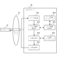
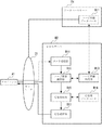
図1を参照すると、本発明の第1の実施の形態は、クライアントA1と名前解決サーバであるDNSサーバB1とによって実現される。クライアントA1とDNSサーバB1はネットワークC1を介して接続されている。DNSサーバB1は、DNSにおける名前解決機能をもつサーバだけではなく、他の用途における名前解決機能をもつサーバとして一般化することもできる。他の用途における名前解決機能をもつサーバの例として、WINS(Windows(R) Internet Name Service)サーバやNIS(Network Information Service)サーバが挙げられる。ただし、以下では名前解決機能を持つサーバとしてDNSサーバを例にとり説明する。
【0088】
クライアントA1は、「www.biglobe.ne.jp」や、「ftp.nec.com」など、ネットワーク上のノードのFQDNに対応するIPアドレスを解決するため、あるいは逆にあるIPアドレスに対応するFQDNを解決するためにDNSサーバB1に対して名前解決要求メッセージとしてDNSクエリメッセージを送信する。他にも、クライアントA1がDNSサーバB1を利用する目的の例としては、RFC2782に記載されているような、ftpやhttpなどのサービス名に対応する該サービスを提供するホストとポート番号の解決や、RFC2916に記載されているような、電話番号に対応するURI(Universal Resource Identifier)の解決などが挙げられる。ただし、以下、DNSサーバB1によってFQDNからIPアドレスの解決またはIPアドレスからFQDNの解決を行なう場合を中心にして説明する。
【0089】
クライアントA1は、送信したDNSクエリメッセージに対して、DNSサーバB1から返される名前解決応答メッセージとしてDNS応答メッセージを受信する。DNS応答メッセージには、名前解決の結果が含まれる。
【0090】
クライアントA1の例としては、一般的にはPC(Personal Computer)や携帯端末、ワークステーションなどの端末ノード(利用端末)が挙げられるが、その他、DNSサーバB1以外の別のDNSサーバが何らかの名前解決を行うためにDNSサーバB1に対して再帰的なDNSクエリを行う場合もあり、このようなDNSサーバをクライアントA1に含めて考えることができる。
【0091】
DNSサーバB1は、クエリ受信部B11と、ユーザ情報識別部B12と、ユーザ情報取得部B13と、ユーザ情報データベースB14と、応答作成部B15と、応答用データベースB16と、応答送信部B17とを含む。
【0092】
DNSサーバB1は、従来のDNSサーバの構成と比べ、ユーザ情報識別部12と、ユーザ情報取得部B13と、ユーザ情報データベースB14とを新たに有する点が大きく異なる。
【0093】
クエリ受信部B11は、クライアントA1が送信したDNSクエリメッセージを受信し、それをユーザ情報識別部B12に渡す。
【0094】
ユーザ情報識別部B12は、DNSクエリメッセージを受け取ると、該メッセージ内に、該メッセージの送信者であるユーザのユーザ属性情報が含まれているかを調べ、含まれている場合は該ユーザ属性情報を読み取って識別する。もし含まれていない場合は、ユーザ情報取得部B13を介してユーザ情報データベースB14からDNSクエリメッセージの送信者のユーザ属性情報を取得する処理を行う。
【0095】
また、ユーザ情報識別部B12は、ユーザ属性情報を取得できた場合は、ユーザ属性情報とDNSクエリメッセージを応答作成部B15に渡す。ユーザ属性情報を取得できなかった場合は、DNSクエリメッセージのみを応答作成部B15に渡す。
【0096】
ここで、ユーザ属性情報とは、例えばユーザ(クライアントA1)のユーザID、位置情報、趣味若しくは行動履歴などの嗜好に関する情報、携帯電話やPDA(Personal Digital Assistants)、ノートパソコンといった利用端末種別、利用端末にインストールされているOS(Operating System)、装備されているネットワークインタフェースやCPU速度、メモリ量といった利用端末に関する情報、利用端末のIPアドレスおよびMACアドレス、ADSL(Asymmetric Digital Subscriber Line)やISDN(Integrated Services Digital Network)といった接続回線種別、接続回線速度、接続しているNAS(Network Access Server)のIPアドレスといったネットワークへの接続状況に関する情報などの、ユーザに関する情報全般を指す。
【0097】
ユーザ情報取得部B13は、DNSサーバB1が受信したDNSクエリメッセージ内に該メッセージの送信者のユーザ属性情報が含まれていない場合に、ユーザ情報識別部B12から渡された情報(該メッセージのソースIPアドレスまたはソースMACアドレスなど)を基にユーザ情報データベースB14から該ユーザ属性情報を取得し、ユーザ情報識別部B12へ渡す。
【0098】
ユーザ情報データベースB14には、DNSサーバB1に対して名前解決を行うユーザのユーザ属性情報及びユーザ属性情報を取得するための参照先が登録されている。ユーザ情報データベースB14には、必要に応じて任意のユーザ属性情報を登録しておくことができる。
【0099】
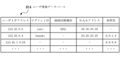
ユーザ情報データベースB14の内容例を図2に示す。図2のユーザ情報データベースB14では、ISP(Internet Service Provider)が運営するネットワークへのログインID、利用端末のIPアドレス、接続回線種別、接続しているNASのIPアドレス、及びユーザ情報データベースB14には直接登録されていないが外部のサーバから必要なユーザ属性情報が取得できる場合に、該ユーザ属性情報を取得するための参照先が登録されている。
【0100】
図2において「―」は、該当する項目の内容がこのユーザ情報データベースB14に登録されていないことを示している。例えば1番目のエントリでは参照先が「―」となっており、このエントリに属性情報が登録されているユーザに関してはこれ以上の属性情報を得るための参照先が不明または存在しないことを示している。また2番目のエントリは、接続回線種別が不明であることが示されており、登録されていないユーザ属性情報については参照先に登録されているIPアドレス「8.9.1.4」で指定されるノードを参照することで取得可能であることが示されている。さらに3番目のエントリでは、利用端末のIPアドレスが「123.45.1.0/24」の範囲にあるユーザ属性情報を、IPアドレスが「9.9.9.9」で指定されるノードを参照することで取得可能であることが示されている。
【0101】
応答作成部B15は、応答用データベースB16を参照し、DNSクエリメッセージにより要求されたFQDN→IPアドレスまたは、IPアドレス→FQDNなどの名前解決処理を行う。ここで、ユーザ情報識別部B12からDNSクエリメッセージと共に、ユーザ属性情報を渡された場合は、ユーザ属性情報を考慮した名前解決処理を行う。ユーザ属性情報を考慮することにより、例えばユーザが動画の配信を行っているサーバのFQDN→IPアドレスの名前解決を要求した際、同一のFQDNに関するDNSクエリであっても、例えば接続回線種別がADSL回線であるユーザには広帯域で配信を行っているサーバのIPアドレスを解決したり、接続回線種別がISDN回線であるユーザには狭帯域で配信を行っているサーバのIPアドレスを解決したりするといったユーザ毎の名前解決処理のカスタマイズを行うことができる。
【0102】
応答用データベースB16には、ユーザの属性毎にFQDN→IPアドレス及び、IPアドレス→FQDNなどの解決方法を示すエントリが登録されている。ユーザ属性情報に依存しないデフォルトの名前解決方法も登録されている。
【0103】
応答用データベースB16の例を図3に示す。図3に示した応答用データベースB16は2種類のテーブルから構成される。一つはFQDN→IPアドレスなどの具体的な名前解決方法が登録されているテーブル(ゾーンファイル)であり、ゾーンファイル202及び203が該当する。このゾーンファイル202、203に登録される主な情報には、エントリの種類を示すTYPE、名前解決のキーとなるFQDN、名前解決により応答するデータを示すDATAがある。用いられるTYPEの例としては、あるFQDNに対応するIPアドレスの解決を示すAレコード、あるFQDNに対応するメールサーバのアドレスの解決を示すMXレコード、あるFQDNの別名を示すCNAMEレコードなどがある。ここで、ゾーンファイル202の1番目のエントリを参照すると、エントリの種類(TYPE)がFQDNからIPアドレスの解決を示すAレコードであり、FQDN:www.aaa.comに対応するIPアドレス(DATA)が「9.8.7.6」であることが示されている。
【0104】
もう一つは、ユーザ属性情報及びドメイン空間毎に名前解決方法の参照先が登録されているテーブル(名前解決テーブル)であり、名前解決テーブル201が該当する。名前解決テーブル201では、ユーザIPアドレス、ユーザID、接続回線種別及びNASのIPアドレスといったユーザ属性情報の組み合わせ毎に、名前解決方法の参照先が登録されている。
【0105】
名前解決テーブル201において、「−」は名前解決の際に考慮しないユーザ属性情報を示している。例えば1番目のエントリでは、ユーザ属性情報のうち、ユーザIPアドレス及びユーザIDは考慮されず、接続回線種別およびNASアドレスのみが考慮されることになる。1番目のエントリは、ユーザIPアドレス及びユーザIDが任意であって、接続回線種別がADSL回線でありかつ、接続しているNASのIPアドレスが「30.30.30.30」であるユーザが、ドメイン空間aaa.comに属するFQDNの問い合わせを行った際に、ゾーンファイルadsl_aaa_com.dat(ゾーンファイル202)が参照されることを示している。同様に、3番目のエントリは、ユーザ属性情報のうち、ユーザIPアドレス、アクセス回線種別及びNASのIPアドレスが任意で、ユーザIDが「jiro」のユーザが、ドメイン空間bbb.comに属するFQDNの問い合わせを行った際に、ゾーンファイルjiro_bbb_com.datが参照されることを示している。また、4番目のエントリは、IPアドレス「123.45.1.5」から、ドメイン空間bbb.comに属するFQDNのDNSクエリがあった場合は、IPアドレス「1.2.3.4」で指定される他のDNSサーバにおいて名前解決処理が行われることを示している。
【0106】
また、最後のエントリ(DEFAULT)にはユーザ属性情報に依存しないデフォルトのIPアドレスの解決方法が登録されている。このエントリは、ユーザ属性情報が名前解決テーブル201に登録されているユーザ属性情報のいずれにも該当しない場合、またはユーザ情報識別部B12においてDNSクエリメッセージに対応するユーザ属性情報が取得できなかった場合に参照される。
【0107】
応答送信部B17は、応答作成部B15から渡された名前解決の処理結果を元にDNS応答メッセージを生成し、クライアントA1へ送信する。
【0108】
次に、図4を参照して、本実施の形態において、DNSサーバB1がDNSクエリメッセージを受信してから応答メッセージを送信するまでの動作について詳細に説明する。
【0109】
クエリ受信部B11は、クライアントA1からDNSクエリメッセージを受信すると(図4のステップS101)、該メッセージをユーザ情報識別部B12に渡す。
【0110】
ユーザ情報識別部B12は、DNSクエリメッセージを受け取ると、該メッセージの送信者のユーザ属性情報の取得処理を行う(ステップS102)。
【0111】
ここで、図5を参照して、ステップS102のユーザ属性情報の取得処理を詳細に説明する。
【0112】
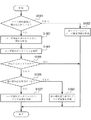
まず、ユーザ情報識別部B12は、受信したDNSクエリメッセージに、ユーザ属性情報が埋め込まれているか否かを判断する(図5のステップS1021)。ユーザ属性情報が埋め込まれている場合はこれを読み出して取得し(ステップS1022)、ユーザ属性情報の取得処理は終了する。
【0113】
ステップS1021でユーザ属性情報が埋め込まれていない場合は、受信したDNSクエリメッセージはユーザ情報識別部B12からユーザ情報取得部B13へ渡され、ユーザ情報取得部B13は該メッセージを送信したユーザを特定する手がかりとなる情報を抽出する(ステップS1023)。抽出する手がかりとなる情報の例としては、DNSクエリメッセージのソースIPアドレスが挙げられる。クライアントA1がユーザ利用端末のリゾルバである場合、DNSクエリメッセージのソースIPアドレスはユーザの利用端末のIPアドレスであるためである。また、クライアントA1がユーザ利用端末のリゾルバであり、クライアントA1とDNSサーバB1が途中にルータを介さず直接接続されている場合は、クライアントA1のソースMACアドレスも同様にDNSクエリメッセージを送信したユーザを特定する手がかりとして利用することができる。
【0114】
次に、ユーザ情報取得部B13は、ユーザ情報データベースB14からステップS1023で抽出した情報に該当するエントリを検索する(ステップS1024)。
【0115】
ステップS1024において、対応するエントリが存在しない場合は、ステップS103の取得処理は終了する(ステップS1025)。
【0116】
ステップS1024において、対応するエントリが存在した場合、ユーザ情報取得部B13は、対応するエントリの内容をもとに、ユーザ属性情報をローカルのユーザ情報データベースB14以外の情報源も参照して取得すべきか否かを判断する(ステップS1025、S1026)。ユーザ属性情報をローカルのユーザ情報データベースB14以外の他の情報源を参照して取得する必要がないと判断した場合は、ユーザ情報取得部B13はステップS1025で発見したエントリからユーザ属性情報を取得する(ステップS1027)。
【0117】
他の情報源も参照してユーザ属性情報を取得すべきと判断した場合は、ユーザ情報取得部B13はステップS1025で発見したエントリからユーザ属性情報を取得するのに加えて、更にユーザ情報データベースB14以外の情報源も参照してユーザ属性情報の取得処理を行う。(ステップS1028)。
【0118】
上記において、ローカルのユーザ情報データベースB14以外の情報源も参照して取得すべきか否かは、ユーザ情報データベースB14に外部のサーバ等の参照先が登録されているかどうかによって判断する。
【0119】
例えば、ユーザ情報データベースB14が図2に示す内容である場合のステップS1025〜S1028の例を述べる。DNSクエリメッセージからユーザを特定する手がかりとなる情報としてソースIPアドレスを抽出し、そのIPアドレスが「123.45.0.2」であった場合、ユーザ情報取得部B13は、ユーザ情報データベースB14からIPアドレスが「123.45.0.2」となっているエントリを検索する(ステップS1025)。この場合発見されるエントリは1番目のエントリであり、その参照先は「―」となっているため、ユーザ情報取得部B13は、他のノード(外部のサーバ等)を参照せず、ユーザ情報データベースB14のみを参照して取得すると判断し(ステップS1026)、1番目のエントリに示されているユーザ属性情報を取得する(ステップS1027)。
【0120】
DNSクエリメッセージのソースIPアドレスが「123.45.0.4」であった場合は、2番目のエントリが発見される。その参照先には、参照先のノードのIPアドレスが登録されているため、ユーザ情報取得部B13は、他のノードを参照すべきだと判断し(ステップS1026)、2番目のエントリに登録されているユーザ属性情報を取得するとともに、登録されているIPアドレスのノードが保持するユーザ属性情報のデータベースからもユーザ属性情報を取得する(ステップS1028)。
【0121】
図4のフローチャートの説明に戻る。ユーザ情報識別部B12は、ステップS102におけるユーザ属性情報取得処理の後、DNSサーバB1が受信したDNSクエリメッセージと該メッセージ送信者のユーザ属性情報とを一緒に応答作成部B15へ渡す。ステップS102において、該メッセージ送信者のユーザ属性情報が取得できなかった場合は、対応するユーザ属性情報はないものとして該メッセージを取り扱い、該DNSクエリメッセージだけを応答作成部B15へ渡す。
【0122】
応答作成部B15は、DNSクエリメッセージと対応するユーザ属性情報を一緒に渡された場合、DNSクエリメッセージで問い合わされたFQDN又はIPアドレス、及びユーザ属性情報に該当するエントリを、応答用データベースB16を参照して検索する(ステップS103)。DNSクエリメッセージだけを受け取った場合は、受け取ったDNSクエリメッセージで問い合わされたFQDN又はIPアドレスに該当するデフォルトのエントリを、応答用データベースB16を参照して検索する(ステップS103)。
【0123】
応答作成部B15は、検索したエントリの内容から名前解決が他のDNSサーバで行われるべきか否かを判断する(ステップS104)。ここでは、図3に示す応答用データベースB16の名前解決テーブル201の参照先として他のDNSサーバのアドレスが登録されている場合に、名前解決が他のDNSサーバで行われるべきと判断される。
【0124】
ステップS104において、他のDNSサーバで行われるべきであると判断した場合は、名前解決処理が他のDNSサーバによって行なわれるように処理する(ステップS106)。名前解決処理が他のDNSサーバで行われるように処理する方法の例として、以下の二つの方法が挙げられる。
【0125】
第1の方法は、他のDNSサーバに、ユーザ情報識別部B12から渡されたユーザ属性情報とDNSクエリメッセージの両方またはDNSクエリメッセージのみを、転送する方法である。この方法を採用する場合の応答作成部B15の構成を図6に示す。
【0126】
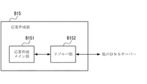
図6を参照すると、応答作成部B15は応答作成メイン部B151とリゾルバ部B152とを含む。応答作成メイン部B151は、上記のステップS103及びステップS104の処理を行い、ステップS104において名前解決が他のDNSサーバで行われるべきであると判断した場合、リゾルバ部B152に対して、ユーザ情報識別部B12から渡されたユーザ属性情報とDNSクエリメッセージの両方またはDNSクエリメッセージのみを渡し、さらに名前解決が行われるべき他のDNSサーバを通知する。リゾルバ部B152は、応答作成メイン部B151から渡された情報を元に、ユーザ属性情報とDNSクエリメッセージの両方またはDNSクエリメッセージのみの転送を行う。
【0127】
リゾルバ部B152がユーザ属性情報とDNSクエリメッセージの両方を他のDNSサーバへ転送する方法としては、例えばDNSクエリメッセージをDNSメッセージのフォーマットに従って構築し、その中にユーザ属性情報を埋め込んで送信する方法が考えられる。DNSメッセージのフォーマットには、付加的な情報を埋め込むために付加情報部と呼ばれるフィールドが用意されており、付加情報部には任意の情報をDNSの資源レコードの形式で埋め込むことができる。
【0128】
この方法では、受け取ったユーザ属性情報を資源レコードの形式にエンコードし、それをDNSクエリメッセージの付加情報部に埋め込み、他のDNSサーバに転送する(ステップS106)。そしてリゾルバ部B152は、該DNSクエリメッセージを転送した他のDNSサーバから、対応するDNS応答メッセージを受信すると、それを応答送信部B17に渡し、応答送信部B17が該応答メッセージをクライアントA1へ転送する(ステップS107)。
【0129】
この転送方法をとることで、ユーザ属性情報が埋め込まれたDNSクエリメッセージを従来のDNSサーバにおいて処理することも可能となるため、本発明によるDNSサーバB1とそれ以外の従来からのDNSサーバの共存を図ることができる。
【0130】
第2の方法は、クライアントA1に、名前解決が他のDNSサーバで行われるべき旨を通知するメッセージをDNS応答メッセージとして返し、通知を受け取ったクライアントA1が改めて他のDNSサーバにDNSクエリメッセージを送信する方法である。この場合、応答送信部B17は、クライアントA1が改めてDNSクエリメッセージを送信すべき他のDNSサーバのIPアドレスを含むDNS応答メッセージをクライアントA1へ送信する(ステップS107)。
【0131】
一方、ステップS104において、応答作成部B15が、自サーバにおいて名前解決を行うべきであると判断した場合は、検索したエントリの内容に従って、FQDN→IPアドレスまたはIPアドレス→FQDNの名前解決を行い(ステップS105)、その結果を応答送信部B17に渡す。
【0132】
応答送信部B17は、受け取った名前解決結果を元にDNS応答メッセージを生成し、それをクライアントA1へ送信する(ステップS107)。
【0133】
以上の第1の実施の形態の説明においては、DNSサーバB1はユーザ情報データベースB14をその構成要素として含むものであった。他の構成として、ユーザ情報データベースB14がDNSサーバB1内ではなく別のサーバ内に保持される形態も考えられる。この場合の構成を第1の実施の形態の他例として図7に示す。
【0134】
この他例では、先に示した図1の構成と比べ、先に示したDNSサーバB1の代わりに、ユーザ情報データベースB14を含まないDNSサーバB2が用いられ、さらに、ユーザ情報データベースD11をその構成要素として含むデータベースサーバD1が用いられる。
【0135】
図7に示す構成におけるDNSサーバB2の動作については、上述したDNSサーバB1の動作においてユーザ情報データベースB14をユーザ情報データベースD11と置きかえることにより同様に考えることができる。
【0136】
データベースサーバD1の機能は、専用のノードにより実現することも、他のDNSサーバB1またはB2の一機能として実現することも可能である。後者の場合、ユーザ情報データベースD11は応答用データベースB16として管理され、ユーザ情報取得部B13は当該他のDNSサーバB1またはB2に対してDNSメッセージを用いてユーザ属性情報を取得することになる。
【0137】
この場合の応答用データベースB16の内容例を図8に示す。図8に示す名前解決テーブル301は、図3に示した名前解決テーブル201と同様の形式をとっており、ユーザ属性情報は3番目のエントリを参照することで取得される。3番目のエントリは、ユーザ属性情報がファイルuser_com.dat(ゾーンファイル302)に格納されていることを示している。ゾーンファイル302には、図2に示したユーザ情報データベースB14と同じユーザ属性情報が格納されており、ユーザ属性情報はユーザの利用端末のIPアドレスを含むFQDNをキーとして、DNSの資源レコードの一種であるTXTレコードの形で格納されている。
【0138】
例えば、ゾーンファイル302の1番目のエントリからは、利用端末のIPアドレスが「123.45.0.2」であるユーザのユーザ属性情報として、ログインIDがtaro(login id=taro)、接続回線種別がADSL回線(access media=ADSL)、接続しているNASのIPアドレスが「30.30.30.30」(NAS address=30.30.30.30)であることが分かる。ユーザ情報取得部B13は、利用端末のIPアドレスが「123.45.0.2」であるユーザのユーザ属性情報を取得したい場合、データベースサーバD1に対して、ドメイン名が「123.45.0.2.user.com」のTXTレコードを要求するDNSクエリメッセージを送信する。
【0139】
次に第1の実施の形態の効果について説明する。
【0140】
本実施の形態では、DNSサーバB1が、ユーザ属性情報が管理されているユーザ情報データベースB14を参照することにより、ユーザ属性情報を考慮した名前解決処理のカスタマイズを行う。ユーザ情報データベースB14に予めユーザ属性情報を登録しておけば、DNSサーバB1は、ユーザ情報データベースB14を参照することで、任意のユーザ属性情報を考慮した名前解決処理を行うことができる。
【0141】
前述のように、従来の技術では、DNSサーバがユーザに関する属性情報として利用できるのは、受信したDNSクエリメッセージのソースIPアドレスだけであった。もしくは、その他の属性情報も利用しようとする場合は、クライアントが送信するDNSクエリメッセージ内に必要な属性情報を全て埋めこむ必要があり、クライアントにおけるリゾルバの変更が必要であった。
【0142】
本実施の形態では、DNSサーバB1はユーザ情報データベースB14を参照することにより、クライアントにおけるリゾルバの変更の必要がない。また、DNSサーバごとに考慮するユーザ属性情報の種類が異なる場合でも、従来技術では対応が困難であったが、本実施の形態によりユーザ情報データベースB14に登録するユーザ属性情報の種類をDNSサーバごとに変えるだけで柔軟かつ容易に実現できる。
【0143】
次に、本発明の第2の実施の形態について図面を参照して詳細に説明する。
【0144】
図9を参照すると、本発明の第2の実施の形態は、図1の第1の実施の形態で示されたクライアントA1とネットワークC1に加え、本発明によるDNSサーバB3と認証サーバE1とを備えて実現される。
【0145】
本発明の第2の実施の形態では、ユーザ情報データベースB14の管理を、DNSサーバB3の構成要素であるユーザ情報管理部B18が認証サーバE1と連携することによって自動的に行う点が、本発明の第1の実施の形態と異なる。以下、クライアントA1、DNSサーバB3、認証サーバE1から構成されるシステムを本システムと呼ぶ。
【0146】
認証サーバE1は、システム内のユーザ(クライアントA1)の認証要求に応じてユーザ認証を行い、ユーザのシステムへのログインを許可または禁止する。ここでのシステムとは、本システムに限らず、例えばISPが運営するネットワークやASP(Application Service Provider)が運営する会員制WEBサービスなど、利用する際にユーザ認証が行われるもの全般を指す。本システム内のユーザは、ここでのシステムのユーザの一部若しくは全てである。
【0147】
認証サーバE1は、ユーザ認証を行うとともに、認証要求を送信したユーザ(クライアントA1)がシステムにログインしたのかログアウトしたのかというユーザのログイン状況を把握し、さらにユーザ属性情報を収集し、これらの情報をログとして保持する。認証サーバE1が収集するユーザ属性情報の例としては、第1の実施の形態の説明で述べたのと同様に、ユーザ(クライアントA1)の位置情報、趣味若しくは行動履歴などの嗜好に関する情報、携帯電話やPDA、ノートパソコンといった利用端末種別、利用端末にインストールされているOS、装備されているネットワークインタフェースやCPU速度、メモリ量といった利用端末に関する情報、利用端末のIPアドレス、ADSL回線やISDN回線といった接続回線種別、接続回線速度、接続しているNASのIPアドレスといったネットワークへの接続状況に関する情報などが挙げられる。
【0148】
認証サーバE1の例としては、ISP等でユーザ認証および課金処理に広く利用されているRADIUSサーバが挙げられる。RADIUSサーバは、RADIUSプロトコルによるユーザ認証処理において、ユーザから受信した認証要求に含まれるIDとパスワードを元にユーザの認証を行い、ユーザのログインを許可または禁止する。RADIUSプロトコルは、ISPが運用するネットワークに限らず、多くのネットワークシステムにおいてユーザ認証に用いられている。
【0149】
また、RADIUSサーバには、ユーザがネットワークシステムにログインまたはログアウトする度に、ユーザのログイン状況及びユーザ属性情報が、NASなどのRADIUSクライアントから送信される。RADIUSサーバは、これらの情報を課金やバックトレースの目的で収集し、Account Logとして保持する。RADIUSクライアントがRADIUSサーバに送信するユーザ属性情報としては、例えばユーザのISPのログインID、ユーザが利用している端末のIPアドレス、ユーザが接続しているNASのIPアドレス、接続回線種別などが含まれる。
【0150】
ユーザ情報管理部B18は、認証情報取得部B181とユーザ情報更新部B182とを含む。
【0151】
認証情報取得部B181は、ユーザのログイン状況の変化を検出し、認証サーバE1からユーザのログイン状況を示す情報及びユーザ属性情報を取得し、これらの情報をユーザ情報更新部B182に渡す。ユーザのログイン状況の変化の検出と、ユーザのログイン状況を示す情報及びユーザ属性情報の取得を実現する方法の例として、次の2つの方法が挙げられる。
【0152】
第1の方法は、認証サーバE1がユーザのログイン状況の変化を検出した際に、ユーザのログイン状況を示す情報とユーザ属性情報とを認証サーバE1から認証情報取得部B181に通知してもらう方法である。
【0153】
第2の方法は、認証情報取得部B181が、認証サーバE1にユーザのログイン状況を問い合わせることによって、ユーザのログイン状況の変化を検出し、ログイン状況の変化を検出した際に、認証サーバE1からユーザのログイン状況を示す情報とユーザ属性情報を取得する方法である。
【0154】
第1の方法では、認証情報取得部B181は認証サーバE1からの通知を待つという受動的な処理で、ユーザのログイン状況の変化を検出するのに対し、第2の方法では、ユーザのログイン状況の変化を検出するために、認証情報取得部B181が認証サーバE1にユーザのログイン状況を問い合わせるという能動的な処理を行う。
【0155】
以下、それぞれの方法の具体例について述べる。
【0156】
まず、第1の方法の具体例としては、RADIUSプロトコルのProxy機能及びRelay機能を利用する方法が挙げられる。Proxy機能は、RADIUSサーバがRADIUSクライアントからユーザのログイン状況及びユーザ属性情報を受信する度に、これらの情報を他のノードへ転送する機能である。Proxy機能は標準化された機能であり、現在利用されているRADIUSサーバのほぼ全てに実装されている。
【0157】
Proxy機能を用いてユーザのログイン状況及び属性情報を取得する場合のシーケンスの例を図10に示す。図10ではユーザがシステムにログインした際のシーケンス例を示している。なお、図10において認証サーバE1はRADIUSサーバである。ユーザ認証が成功し、ユーザがシステムにログインすると、RADIUSクライアントから認証サーバE1に対して、Accounting
Requestメッセージが送信される。
【0158】
Accounting Requestメッセージには、ユーザ属性情報が、属性=属性値の形で含まれている。図に示した例では、Accounting Requestメッセージに、ユーザIDがtaro((1)User Name = taro)、NASのIPアドレスが「30.30.30.30」((4)NAS−IP−Address = 30.30.30.30)、ユーザ利用端末のIPアドレスが123.45.0.2((8)Framed−IP−Address = 123.45.0.2)、接続回線種別がADSL((61)NAS−Port−Type=ADSL)であることを示す情報が含まれる。また、ユーザがシステムにログインした旨を示す情報((40)Acct−Status−Type=Start )も含まれる。
【0159】
認証サーバE1はAccounting Requestメッセージを受信すると、Proxy機能を利用して、受信したAccounting Requestメッセージをユーザ情報管理部B18へ送信する。ユーザ情報管理部B18は受信したAccounting Requestメッセージからユーザ属性情報を取得する。ユーザ情報管理部B18は、Accounting Requestメッセージを受信後、認証サーバE1に対してAccounting Responseメッセージを送信する。
【0160】
次に、Relay機能を用いたユーザ情報の取得について説明する。Relay機能は、Account Logに新たなログが追加されるたびに、RADIUSサーバがそれを他のノードへ送信する機能である。Relay機能はデファクト化された機能であり、多くのRADIUSサーバに実装されている。
【0161】
Relay機能を用いてユーザのログイン状況及び属性情報を取得する場合のシーケンスの例を図11に示す。図11では、ユーザがシステムにログインした際のシーケンスを示している。なお、図11において認証サーバE1はRADIUSサーバである。ユーザ認証が成功し、ユーザがシステムにログインすると、認証サーバE1が保持するAccount Logに新たなログが追加される。認証サーバE1は新たに追加されたログを元に、Accounting Requestメッセージを生成し、これをユーザ情報管理部B18へ送信する。
【0162】
図11では、Accounting Requestメッセージに、ユーザIDがtaro((1)User Name = taro)、NASのIPアドレスが「30.30.30.30」((4)NAS−IP−Address =30.30.30.30)、ユーザ利用端末のIPアドレスが123.45.0.2((8)Framed−IP−Address = 123.45.0.2)、接続回線種別がADSL((61)NAS−Port−Type=ADSL)であることを示す情報が含まれる。また、ユーザがシステムにログインした旨を示す情報((40)Acct−Status−Type=Start )も含まれる。ユーザ情報管理部B18は受信したAccounting Requestメッセージからユーザ属性情報を取得する。ユーザ情報管理部B18は、Accounting Requestメッセージを受信後、認証サーバE1に対してAccounting Responseメッセージを送信する。
【0163】
次に、第2の方法の具体例を説明する。認証情報取得部B181は、定期的にユーザのログイン状況を問い合わせるメッセージを認証サーバE1に送信し、ユーザのログイン状況に変化があるか否かを確認する。ユーザのログイン状況に変化がある場合には、認証サーバE1に対して、ユーザのログイン状況を示す情報とユーザ属性情報の送信を要求する。
【0164】
第2の方法の更に具体的な例としては、NFS(Network File System)機能を用いる方法とSNMP(Simple Network Management Protocol)を用いる方法が挙げられる。NFSは、TCP/IP環境で一般的に使用されるネットワーク経由のファイルサービスであり、ネットワークで接続されている他のノードが保持するファイルを、自ノード上にマウントすることにより、あたかもローカルファイルのように扱えるようにする機能を持つ。NFS機能を用いる方法では、ユーザ情報管理部B18が、認証サーバE1が保持するユーザのログイン状況とユーザ属性情報を含むログファイルを、マウントする。認証情報取得部B181は、自ノード上にマウントされているログファイルを定期的にチェックすることにより、ユーザのログイン状況の変化を検出する。ユーザのログイン状況の変化を検出した場合は、マウントされているログファイルから、ログイン状況が変化したユーザ属性情報を取得する。
【0165】
一方、SNMPはTCP/IPネットワーク環境で、他のノードの管理及び監視を行うためのプロトコルである。管理する側の「SNMPマネージャ」と管理される側の「SNMPエージェント」の2つでMIB(Management Information Base)と呼ばれる管理情報を交換することで、他のノードの管理が行なわれる。SNMPを用いる方法では、認証情報取得部B181がSNMPマネージャとなり、認証サーバE1をSNMPエージェントとして、認証サーバE1のMIBのうち、ユーザのログイン状況を示す部分を定期的にチェックする。ユーザのログイン状況の変化を検出した場合は、認証サーバE1のMIBから、ログイン状況が変化したユーザ属性情報に該当する部分を取得する。
【0166】
ユーザ情報更新部B182は、認証情報取得部B182から渡された情報を基に、ユーザ情報データベースB14の管理を行う。例えば、本システムにログインしたユーザのユーザ属性情報をユーザ情報データベースB14に追加したり、逆にログアウトしたユーザのユーザ属性情報をユーザ情報データベースB14から削除したりする。
【0167】
次に、第2の実施の形態の動作を図面を参照して詳細に説明する。なお、DNSサーバB1がクライアントA1からDNSクエリメッセージを受信してからDNS応答メッセージを送信するまでの動作は、図4で示した第1の実施の形態における動作と同一のため説明は省略する。以下、図12を参照して、ユーザ情報管理部B18における、ユーザ情報データベースB14の管理について詳細に説明する。
【0168】
認証情報取得部B181は、ユーザのログイン状況の変化を検出すると(図12のステップS201)、当該ログイン状況の変化がユーザのログインかログアウトかを判断する(ステップS202)。
【0169】
ユーザがシステムへログインした場合は、認証サーバE1からユーザのログイン状況を示す情報とユーザ属性情報を取得し、これらの情報をユーザ情報更新部B182に渡す(ステップS203)。ユーザ情報更新部B182は、ユーザのログイン状況を示す情報を調査し、ユーザ属性情報をユーザ情報データベースB14に追加登録する(ステップS204)。
【0170】
ステップS202で、ユーザがシステムからログアウトした場合は、認証情報取得部B181が認証サーバE1からユーザのログイン状況を示す情報とユーザ属性情報を取得し、これらの情報をユーザ情報更新部B182に渡し(ステップS205)、ユーザ情報更新部B182がユーザ属性情報を元にユーザ情報データベースB14からユーザに該当するエントリを検索し、そのエントリを削除する(ステップS206)。
【0171】
以上の第2の実施の形態の説明において、DNSサーバB1はユーザ情報データベースB14をその構成要素として含むものであった。他の構成として、第1の実施の形態と同様に、ユーザ情報データベースB14がDNSサーバB1内ではなく別のサーバ内に保持される形態も考えられる。この場合の構成を第2の実施の形態の他例として図13に示す。
【0172】
図13に示す構成では、先に示した図9の構成と比べ、先に示したDNSサーバB3の代わりに、ユーザ情報データベースB14を含まないDNSサーバB4が用いられ、さらに、ユーザ情報データベースD11をその構成要素として含むデータベースサーバD1が用いられている。
【0173】
なお、図13に示す構成において、従来のDNSサーバまたは本発明におけるDNSサーバB1、B2、B3、B4(後述する第3の実施の形態におけるDNSサーバB5も含む)をデータベースサーバD1の用途として用いてもよい。この場合、DNSサーバにおける応答用データベースB16がユーザ情報データベースD11として用いられる。
【0174】
また、この場合、ユーザ情報更新部B182がユーザ情報データベースD11に対してユーザ属性情報を更新する方法として、DNS Dynamic Updateを用いる方法が考えられる。DNS Dynamic Updateとは、DNSサーバが保持するデータベースに対して、エントリの追加及び削除を他のノードから行うための方式である。DNS Dynamic Updateを行うノードは、追加または削除を行う情報をDNSで規定されている資源レコードの形式にエンコードし、これを埋め込んだメッセージをDNSサーバに送信する。DNSサーバはメッセージを受信すると、保持する応答用データベースに対してエントリの追加または削除を行う。
【0175】
DNS Dynamic Updateを用いる方法では、ユーザ情報更新部B182が、認証情報取得部B181から渡されたユーザ属性情報をDNSの資源レコードにエンコードし、これを埋め込んだメッセージをDNSサーバに送信する。DNSサーバは、メッセージを受信すると、応答用データベース(ユーザ情報データベースD11に対応)に対して、メッセージに埋め込まれた資源レコードに該当するエントリを追加または削除する。作成される応答用データベース内のエントリの例として、図8に示したゾーンファイル302が挙げられる。
【0176】
図13に示す構成におけるDNSサーバB4の動作については、上述したDNSサーバB3の動作において、ユーザ情報データベースB14をユーザ情報データベースD11と置き換えることにより、同様に考えることができる。
【0177】
次に、第2の実施の形態の効果について説明する。
【0178】
DNSサーバが名前解決をカスタマイズするために必要なユーザ属性情報を取得して管理するにあたって、該属性情報を人的に管理するのは非常に手間とコストがかかることになる。
【0179】
例えば、ISP(Internet Service Provider)網には膨大な数のユーザが存在し、さらに個々のユーザの属性情報(位置、IPアドレス、接続回線種別など)は動的に変化するため、これを人的に管理するのは極めて困難となる。
【0180】
本実施の形態では、ユーザ情報管理部B18が、認証サーバE1と連携することにより、ユーザ情報データベースB14の管理を行う。ユーザ情報データベースB14に対するユーザ属性情報の登録及び削除が、ユーザ情報管理部B18により自動的に行われる。このため、ユーザ情報データベースB14の設定管理(ユーザ属性情報の登録及び削除)に要する手間やコストを第1の実施の形態と比較して低減することができる。
【0181】
また、本実施の形態では、認証情報取得部B181は認証サーバE1からユーザ情報を取得するが、ユーザ情報の取得にあたり、認証サーバに特別な機能を必要とならない。ユーザ情報を取得する方法として、上記ではRADIUSサーバのProxy機能またはRelay機能を用いる方法、NFSを用いる方法及びSNMPを用いる方法を例として示したが、これらの機能は標準化またはデファクト化された機能であり、今日利用されている多くの認証サーバにおいて設定変更を行うのみで利用可能な機能である。したがって本システムを既存のシステムに導入する際、新たな認証サーバを設置したり、既存の認証サーバを専用の認証サーバに置き換えたりするなどの導入コストが必要ない。また、本システム導入後も、同一の認証サーバで認証処理やログの収集が行われるため、既存のシステムにおける認証処理や課金処理などの運用形態を変更するためのコストが発生しない。
【0182】
次に、本発明の第3の実施の形態について図面を参照して詳細に説明する。
【0183】
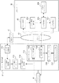
図14を参照すると、本発明の第3の実施の形態は、図9の第2の実施の形態で示されたクライアントA1と認証サーバE1に加え、DNSサーバB5とパケット転送装置F1とを備えて実現される。DNSサーバB5と認証サーバE1とパケット転送装置F1は、ネットワークC1によって相互接続される。クライアントA1がネットワークC1側と送受信するパケットは、必ずパケット転送装置E1を経由する。ここでパケット転送装置とは、イーサネット(R)スイッチ、ATMスイッチ、ルータ、レイヤ4スイッチ、レイヤ7スイッチなど、パケットの転送処理機能をもつ装置全般を指す。
【0184】
DNSサーバB5は、図1に示した第1の実施の形態におけるDNSサーバB1の構成と比べ、ユーザ情報取得部B13およびユーザ情報データベースB14をその構成要素として必要としない点が異なる。以下、DNSサーバB5を含む構成について説明するが、DNSサーバB5の代わりに第1、第2の実施の形態で示したDNSサーバB1、B2、B3、B4のいずれかを用いてもよい。
【0185】
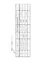
また、応答用データベースB16において登録される内容例を図15に示す。この応答用データベースB16には、名前解決テーブル401、ゾーンファイル402、403が含まれている。名前解決テーブル401およびゾーンファイル402(または403)はそれぞれ、本発明の第1の実施の形態において説明した図3における名前解決テーブル201およびゾーンファイル202(または203)に対応するものである。
【0186】
ここで、第3の実施の形態では、ユーザ属性情報として、第1、第2の実施の形態で述べたユーザ属性情報の例に加えて、パケット転送装置に関する属性情報を含めて取り扱うものとする。すなわち、名前解決テーブル401は、名前解決テーブル201と比べ、ユーザ属性情報として、ユーザIDや接続回線種別といった属性情報だけではなく、パケット転送装置F1に関する属性情報を含み、このパケット転送装置F1に関する属性情報毎にも名前解決方法の参照先が登録できる点が異なる。ここで、パケット転送装置F1に関する属性情報の例として、パケット転送装置F1の識別子(ID)、パケット転送装置F1がサポートする転送方法(例として、イーサネット(R)のvlanをサポートするか、URLベースのスイッチングをサポートするか、など)などの情報が挙げられる。
【0187】
図15に示す名前解決テーブル401では、ユーザ属性として、ユーザID、接続回線種別、グループIDといった属性情報だけではなく、パケット転送装置IDを含み、このパケット転送装置ID毎にも名前解決方法の参照先が登録できるようになっている。また、ゾーンファイル402(または403)は、ゾーンファイル202(または203)で示したフィールド(Type,FQDN,Data)に加え、各エントリにおける付加的な情報を格納するフィールド(Additional Data)をもつ点が異なる。
【0188】
本実施の形態では、この付加的な情報を格納するフィールドを、パケット転送装置F1におけるパケットに対する転送方法を格納するために用いる。パケットに対する転送方法の例として、該パケットを転送する優先度(パケット転送優先度)、該パケットが転送されるべき論理ネットワーク(VPN(VirtualPrivate Network)、vlanなど)のID(論理ネットワークID)、該パケットが転送される論理チャネル(ATMのVCI(Virtual Channel Identifier)、MPLS(MultiProtocol Label Switching)のLSP(Label Switched Path)など)のID、該パケットのヘッダに対する書き換え・追加・削除の方法、などが挙げられる。
【0189】
ゾーンファイル402における1番目のエントリでは、www.ddd.comに対するAレコードの応答は「20.1.1.1」であり、さらに、クライアントA1が該エントリを参照した結果送信する、宛先IPアドレスが「20.1.1.1」であるパケットに対して、パケット転送装置F1において、ソースIPアドレス(SrcIPAddr)を「40.1.1.1」に書換え、MACヘッダ内のvlan−ID(vlanID)を「111」に書換え、出力ポート21から、通常の転送優先度(priority)で転送するという転送方法を用いるということを示している。
【0190】
応答作成部B15は、DNSクエリメッセージに対するDNS応答メッセージを作成するときに、参照される応答用データベースB16内のエントリにおいてAdditional Dataフィールドが登録されている場合は、作成されるDNS応答メッセージ内に、Additional Dataに記されている内容を格納する。この格納方法として、先に述べたDNSメッセージにおける付加情報部にAdditional Dataに記されている内容を格納するなどの方法が挙げられる。
【0191】
DNS応答メッセージにおける付加情報部にAdditional Dataに記されている内容を格納することにより、該応答メッセージは、クライアントA1から問合わせされたFQDNに対するIPアドレス(またはその他のリソースレコードデータ)だけではなく、パケット転送装置F1におけるクライアントA1から該IPアドレス宛てに送信されたパケットに対する転送方法も同時に含むことができる。
【0192】
パケット転送装置F1は、ユーザ認証部F11と、ユーザ情報更新部F12と、ユーザ情報データベースF13と、ユーザ情報取得部F14と、DNSプロキシ部F15と、ルーティングテーブルF16と、フォワーディング部F17とを含む。
【0193】
ユーザ認証部F11は、パケット転送装置F1に対して接続するクライアントA1におけるユーザを識別、認証する機能を有する。さらに、認証時に得られたユーザのさまざまなユーザ属性情報を、ユーザ情報更新部F12を介してユーザ情報データベースF13に格納する。パケット転送装置F1においてユーザ認証を行う代表的な例として、イーサネット(R)スイッチにおいて標準化されているユーザ認証機構であるIEEE 802.1xが挙げられる。
【0194】
パケット転送装置F1がIEEE 802.1xをサポートする場合、クライアントA1上のユーザのユーザID、パスワードなどの情報を基にして、ユーザ認証部F11が認証サーバC1とRADIUSプロトコルを用いて通信を行って認証を行うことにより、クライアントA1がネットワークC1側と通信することを許可すべきかどうか判定する。
【0195】
ユーザ情報更新部F12は、ユーザ認証部F11から渡された情報を基に、ユーザ情報データベースF13の管理を行う。例えば、パケット転送装置F1にログインして通信を行うユーザのユーザ属性情報をユーザ情報データベースF13に追加し、逆にログアウトしたユーザのユーザ属性情報をユーザ情報データベースF13から削除するといった処理を行なう。
【0196】
ユーザ情報データベースF13は、ユーザ認証部F11が認証したユーザのユーザ属性情報を格納するデータベースである。ユーザ情報データベースF13に格納されるユーザ属性情報の例は、第1の実施の形態で述べたユーザ属性情報の例と同様である。ユーザ情報データベースの例を、図16のユーザ情報データベース501に示す。ユーザ情報データベース501では、パケット転送装置F1が受信したパケットに対応する入力ポートおよびソースMACアドレスに対して、該パケットのユーザID,接続回線種類、接続回線速度、グループIDが記述されている。
【0197】
例えば、1番目のエントリでは、入力ポートが「02」で、ソースMACアドレスが「00:12:34:56:78:9a」であるパケットに対しては、該パケットの送信者のユーザIDが「taro」であり、接続している回線の種類がイーサネット(R)であり、その速度が100Mbpsであり、該パケット送信者が含まれるグループのIDが「silver」であることを示している。
【0198】
ユーザ情報取得部F14は、DNSプロキシ部F15内のクエリ書換部F151において受信したDNSクエリメッセージの送信者に対応するユーザ属性情報を、ユーザ情報データベースF13から取得し、該ユーザ属性情報をクエリ書換部F151へ渡す機能を有する。
【0199】
DNSプロキシ部F15は、クライアントA1とDNSサーバB5との間に流れるDNSクエリメッセージおよびDNS応答メッセージに対してその内容を読み込んで解析し、メッセージの内容を書きかえて送信する機能を有する。DNSプロキシ部F15は、その構成要素として、クエリ書換部F151と応答解析部F152とを含む。
【0200】
クエリ書換部F151は、クライアントA1がDNSサーバB5へ向けて送信したDNSクエリメッセージに対して、該DNSクエリメッセージを送信したユーザに関するユーザ属性情報を該DNSクエリメッセージに対して付加してDNSサーバB5へ送信する機能を有する。この際に必要に応じてユーザ属性情報にパケット転送装置F1に関する属性情報を含めることができる。ここで、該DNSクエリメッセージを送信したユーザに関するユーザ属性情報は、ユーザ情報取得部F14を介してユーザ情報データベースF13から取得され、必要に応じてパケット転送装置F1に関する属性情報が付加される。
【0201】
応答解析部F152は、DNSサーバB5がクライアントA1へ向けて送信したDNS応答メッセージから、該メッセージ内に埋めこまれたパケット転送方法を抽出する機能を有する。さらに、抽出したパケット転送方法に対応するエントリをルーティングテーブルF16に登録する。
【0202】
ルーティングテーブルF16は、フォワーディング部F17が受信したパケットの転送方法が格納されたデータベースである。ルーティングテーブルF16が示すテーブルの例として、ルータにおける受信パケットの転送方法が格納されたテーブル、イーサネット(R)スイッチにおけるスイッチング方法が格納されたテーブル、などが挙げられる。ルーティングテーブルF16内のエントリは、従来のように、静的に設定されたりあるいはルーティングプロトコルによって動的に得られた情報を基に作成される方法の他に、応答解析部F152によって作成されることも可能である。
【0203】
ルーティングテーブルF16の内容例を図17に示す。ルーティングテーブルF16における2番目のエントリでは、パケット転送装置F1が受信したパケットの入力ポート、ソースMACアドレス、宛先IPアドレス、vlan−IDがそれぞれ「11」、「00:bc:de:f0:12:34」、「60.1.1.1」、「200」である場合に、該パケットに対して、ソースIPアドレス、宛先IPアドレス、vlan−IDをそれぞれ、「40.1.1.1」、「90.1.1.1」、「333」に書換え、出力ポート「31」から送信するということを示している。さらに、優先度が「優先」となっており、パケット転送の優先度を高くして送信することを示している。
【0204】
フォワーディング部F17は、パケット転送装置F1が受信したパケットの転送方法を解決し、該転送方法に基づいて該パケットを転送する機能を有する。ここで受信したパケットの転送方法は、ルーティングテーブルF16を参照することにより解決される。
【0205】
次に、本実施の形態において、クライアントA1がDNSクエリメッセージをDNSサーバB5に対して送信し、対応するDNS応答メッセージがクライアントA1へ返されるまでのパケット転送装置F1およびDNSサーバB5の動作を図面を参照して詳細に説明する。
【0206】
まず、クライアントA1がDNSサーバB5へDNSクエリメッセージを送信した際のパケット転送装置F1における動作を図18のフローチャートを参照して説明する。
【0207】
クライアントA1がDNSクエリメッセージをネットワークC1側へ送信すると、パケット転送装置F1は該メッセージを検出し、該メッセージを受信する。パケット転送装置F1によって受信されたDNSクエリメッセージは、DNSプロキシ部F15内のクエリ書換部F151へと渡される(図18のステップS301)。
【0208】
ここで、該メッセージには、宛先IPアドレスとしてDNSサーバB5のIPアドレスが指定されているため、該メッセージだけを通常のパケットと同様に転送せずにクエリ書換部F151へ渡す方法が必要となる。この方法として、DNSクエリメッセージであることを示す特定のポート番号をもつパケットだけをクエリ書換部F151へ渡す(一般的にDNSクエリメッセージは宛先ポート番号53番であるパケットであることを基に識別できる)、などの方法がある。
【0209】
次に、クエリ書換部F151において、受信したDNSクエリメッセージの送信者のユーザ属性情報をユーザ情報データベースF13を参照することにより検索する(ステップS302)。
【0210】
例えば、ユーザ情報データベースF13が、図16に示したユーザ情報データベース501と同じエントリを格納しているとすると、ポート11から受信し、ソースMACアドレスが「00:bc:de:f0:12:34」であるDNSクエリメッセージは、ユーザ情報データベースF13を参照することにより、送信者のユーザIDが「hanako」であり、接続回線の種類がイーサネット(R)であり、接続回線の速度が10Mbps等のユーザ属性情報が検索される。グループIDの項目は「―」となっており、グループIDが不明であるか、あるいは取得する必要のない属性であることを示している。
【0211】
ステップS302におけるユーザ属性情報の検索の結果、受信したDNSクエリメッセージの送信者に対応するユーザ属性情報が存在する場合、クエリ書換部F151で対応するユーザ属性情報を該DNSクエリメッセージに付加し、該メッセージをDNSサーバB5へ送信する(ステップS303、S304)。
【0212】
ステップS304において、ユーザ情報データベースF13を参照して解決したユーザ属性情報の他、ユーザ属性情報としてパケット転送装置F1に関する属性情報を該DNSクエリメッセージに対して付加する必要があれば、パケット転送装置F1に関する属性情報も該メッセージに付加し、DNSサーバB5へ送信する。例えば、ユーザ情報データベースF13を参照して解決したユーザ属性情報の他に、パケット転送装置F1のIDを該メッセージに対して付加する。
【0213】
ステップS302におけるユーザ属性情報の検索の結果、受信したDNSクエリメッセージの送信者に対応するユーザ属性情報が存在しなかった場合、クエリ書換部F131は該メッセージに対しては何も情報を付加することなくそのままDNSサーバB5へ送信する(ステップS303、S305)。
【0214】
次に、DNSサーバB5がパケット転送装置F1を経由してDNSクエリメッセージを受信した際のDNSサーバB5における動作について図19を参照して説明する。
【0215】
まず、クエリ受信部B11がDNSクエリメッセージを受信すると(図19のステップS401)、該メッセージをユーザ情報識別部B12へ渡す。
【0216】
ユーザ情報識別部B12は、受け取ったDNSクエリメッセージ内に、送信者のユーザ属性情報が埋めこまれているかどうかを識別する(ステップS402)。
【0217】
ステップS402の結果、該メッセージ内に、送信者のユーザ属性情報が埋めこまれている場合は、埋めこまれている送信者のユーザ属性情報を読み出し識別し、識別したユーザ属性情報と一緒に該メッセージを応答作成部B15へ渡す(ステップS403)。
【0218】
ステップS402の結果、該メッセージ内に、送信者のユーザ属性情報が埋めこまれていない場合は、該メッセージに対応する送信者のユーザ属性情報はないものとして該メッセージを応答作成部B15へ渡す。
【0219】
ステップS402、S403の後、ステップS404〜ステップS408の動作については、第1の実施の形態において説明した図4のステップS103〜ステップS107と同様である。
【0220】
また、ステップS408では、応答作成部B15が作成したDNS応答メッセージにおいて、パケット転送装置F1におけるパケット転送方法も同時に付加されている場合、応答送信部B17はパケット転送装置F1におけるパケット転送方法を含むDNS応答メッセージをクライアントA1に対して送信する。
【0221】
次に、パケット転送装置F1がDNSサーバB5からDNS応答メッセージを受信したときの動作を図20のフローチャートを参照して説明する。
【0222】
DNSサーバB5がDNS応答メッセージをクライアントA1へ送信すると、パケット転送装置F1は該メッセージを検出し、該メッセージを受信する。パケット転送装置F1によって受信されたDNS応答メッセージは、DNSプロキシ部F15内の応答解析部F152へと渡される(図20のステップS501)。
【0223】
ここで、該メッセージには、宛先IPアドレスとしてクライアントA1のアドレスが指定されているため、該メッセージだけを通常のパケットと同様に転送せずに応答解析部F152へ渡す方法が必要となるが、この方法に関しては、図18のステップS301の動作の説明で述べた方法と同様に考えられる(DNS応答メッセージはソースポート番号53番であるパケットであることを基に識別できる)。
【0224】
次に、応答解析部F152は、受信したDNS応答メッセージの内容を調べ、該メッセージにパケット転送装置F1におけるパケット転送方法が埋めこまれているかどうかを調べる(ステップS502)。
【0225】
ステップS502の結果、パケット転送方法が埋めこまれている場合、応答解析部F152は埋めこまれたパケット転送方法を読み出す(ステップS503)。以下、DNSサーバB5において、図15に示したゾーンファイル402における1番目のエントリを用いてDNS応答メッセージが作成され、該メッセージがDNSサーバB5からクライアントA1へ送信された場合について説明する。
【0226】
次に、応答解析部F132はルーティングテーブルF16内に登録されているエントリを参照し、受信したDNS応答メッセージ内に埋めこまれたパケット転送方法から作成されるエントリと同一のエントリが存在するかどうか調べる(ステップS504、S505)。
【0227】
ステップS505の結果、同一の転送方法を示すエントリが存在しない場合、応答解析部F152は、ルーティングテーブルF16に対して、受信したDNS応答メッセージ内に埋めこまれたパケット転送方法に対応するエントリを作成する(ステップS506)。
【0228】
ここで、ルーティングテーブルF16に対してパケット転送方法を示すエントリを作成する例を示す。DNSサーバB5が、図15に示した応答用データベースB16におけるゾーンファイル402の1番目のエントリを用いてDNS応答メッセージを作成し、クライアントA1へ向けて送信された該メッセージをパケット転送装置F1が受信したとする。さらに、該メッセージの送信先であるクライアントA1のMACアドレスが「00:12:34:56:78:9a」であり、クライアントA1とパケット転送装置F1との間は、パケット転送装置F1のポート「02」を経由し、vlan−IDが「100」のイーサネット(R)vlanを用いて転送されるとすると、図17に示したルーティングテーブルF16における1番目のエントリが作成される。
【0229】
ステップS505の結果、同一の転送方法を示すエントリが存在する場合は、重複するエントリを作成することを避けるために、ステップS506の動作はスキップする。
【0230】
次に、応答解析部F152は、受信したDNS応答メッセージ内に埋めこまれたパケット転送方法を該メッセージから削除し(ステップS507)、該メッセージをクライアントA1に対して転送する(ステップS508)。
【0231】
ステップS502の結果、パケット転送方法が埋めこまれていない場合は、応答解析部F152は、受信したDNS応答メッセージをそのままクライアントA1に対して転送する(ステップS508)。
【0232】
以上で図14を用いて説明した本実施の形態において、パケット転送装置F1内のユーザ情報データベースF13は、ユーザ認証部F11と認証サーバE1との間での認証時に得られたユーザ属性情報をユーザ認証部F11がユーザ情報更新部F12を介して格納することによって作成された。この他にも、パケット転送装置F1の管理者などによって、外部から手動でユーザ情報データベースF13内にユーザ属性情報が書きこまれる形態も考えられる。この場合、ユーザ認証部F11およびユーザ情報更新部F12および認証サーバE1は本実施の形態における構成要素としては必要ない。
【0233】
また、図14を用いて説明した第3の実施の形態において、パケット転送装置F1はユーザ情報データベースF13をその構成要素として含むものであった。他の構成として、ユーザ情報データベースF13がパケット転送装置F1内ではなく、他のサーバ(外部データベースなど)内に保持される形態も考えられる。この場合の構成を第3の実施の形態の他例として図21に示す。
【0234】
図21に示す構成では、先に示した図14の構成に比べ、先に示したパケット転送装置F1に代わりに、ユーザ情報データベースF13を含まないパケット転送装置F2が用いられ、さらに、第1の実施の形態の説明において図7で示したデータベースサーバD1が用いられる。データベースサーバD1の機能は、第1の実施の形態で説明したのと同様に、DNSサーバB1、B2あるいはB5の一機能として実現することも可能である。この場合、ユーザ情報取得部F14はDNSメッセージを用いてユーザ属性情報の取得を行う。
【0235】
図21に示す構成におけるパケット転送装置F2の動作については、上述したパケット転送装置F1の動作の説明において、ユーザ情報データベースF13をユーザ情報データベースD11と置きかえることにより同様に考えることができる。
【0236】
さらに、図14を用いて説明した本実施の形態において、パケット転送装置のDNSプロキシ部F15がクエリ書換部F151と応答解析部F152との両方を有する構成について説明したが、DNSプロキシ部F15が、クエリ書換部F151または応答解析部F152のいずれか一方のみを有する構成も考えられる。
【0237】
DNSプロキシ部F15がクエリ書換部F151のみを有するパケット転送装置F3の構成例を図22に示す。この構成の場合、パケット転送装置F3は、クライアントA1から受信したDNSクエリメッセージに対して送信者のユーザ属性情報を埋めこみ、DNSサーバB5へ送信する一方、DNSサーバB5から返されたDNS応答メッセージに対しては、そのままクライアントA1へ送信する。
【0238】
また、DNSプロキシ部F15が応答解析部F152のみを有するパケット転送装置F4の構成例を図23に示す。この構成の場合、パケット転送装置F4は、クライアントA1から受信したDNSクエリメッセージに対してはそのままDNSサーバB5へ送信する一方、DNSサーバB5から返されたDNS応答メッセージに対しては、埋めこまれたパケット転送方法を抽出し、ルーティングテーブルに対してエントリの作成を行う。
【0239】
次に、第3の実施の形態の効果について説明する。
【0240】
本実施の形態では、クライアントA1がDNSサーバB5に対して送信したDNSクエリメッセージを、パケット転送装置F1が途中で一旦受信し、該DNSクエリメッセージを送信したユーザに関するユーザ属性情報を該DNSクエリメッセージに埋め込む。この際に必要に応じてユーザ属性情報としてパケット転送装置F1に関する属性情報をも埋め込みDNSサーバB5へ転送する。さらに、DNSサーバB5は該DNSクエリメッセージを受信すると、該DNSクエリメッセージ内に埋め込まれたユーザ属性情報を基に、DNS応答および該応答に対応するパケット転送装置F1におけるパケット転送方法をDNS応答メッセージに埋めこみクライアントA1へ送信する。パケット転送装置F1は、該応答メッセージを一旦受信し、該応答メッセージ内に埋めこまれたパケット転送方法を抽出してルーティングテーブルF16に対応するエントリを作成する。
【0241】
従来、DNSサーバからクライアントに対して送信されたDNS応答メッセージは、クライアントが利用するものであったが、本実施の形態により、クライアントだけではなく、クライアントとDNSサーバ間に設置されているパケット転送装置も該DNS応答メッセージ内に格納された情報を利用することが可能になる。
【0242】
本実施の形態では、該DNS応答メッセージ内に、該応答メッセージを受信した結果クライアントが送信するパケットに対するパケット転送装置F1における転送方法が埋めこまれる。これにより、例えばWebのアプリケーションの場合、クライアントA1に負荷の低いWebサーバに接続させると同時に、パケット転送装置F1においてクライアントA1と該Webサーバ間の接続上を通過するパケットに対して優先的に転送させる、などといった制御をDNSサーバが行うことが可能になる。
【0243】
さらに、本発明の第1の実施の形態で述べたDNS応答のカスタマイズ機能により、パケット転送装置F1における転送方法の制御も同様にユーザ属性情報およびパケット転送装置F1に関する属性情報を基にカスタマイズすることが可能である。例えば、特権ユーザの送受信するパケットは優先的に転送したり、特権ユーザ用のvlanを用いて転送するなどの制御を行うことが可能となる。
【0244】
【実施例】
次に、本発明の第1の実施例を、図面を参照して説明する。かかる実施例は本発明の第1の実施の形態に対応するものである。また、本実施例は図1に示した構成をとるものとする。実施例において、クライアントA1は、DNSサーバB1に対して名前解決を要求するユーザが利用する端末である。また、DNSサーバB1は図2に示した内容をユーザ情報データベースB14として保持し、図3に示した名前解決テーブル201、ゾーンファイル202、203を応答用データベースB16として保持するものとする。
【0245】
今、IPアドレスが「123.45.0.2」である端末を利用するユーザ1と、IPアドレスが「123.45.0.4」である端末を利用するユーザ2がFQDN:www.aaa.comの名前解決をDNSサーバB1に要求したとする。www.aaa.comは、地域情報を提供するウェブサイトのFQDNであり、かかるウェブサイトでは、アクセスしてくるユーザの位置情報(接続しているNASのIPアドレス)とネットワークへの接続回線種別を考慮し、これらのユーザ属性情報に適したウェブページを表示するサービスが提供されているものとする。
【0246】
具体的に川崎市からネットワーク接続しているユーザ(以下では、IPアドレスが「30.30.30.30」のNASに接続しているユーザが川崎市からネットワーク接続しているユーザであるものとする)には、川崎市の地域情報が提供され、横浜市からネットワーク接続しているユーザ(以下では、IPアドレスが「20.20.20.20」のNASに接続しているユーザが横浜市からネットワーク接続しているユーザであるものとする)には、横浜市の地域情報が提供される。
【0247】
また、ADSL回線で接続しているユーザには、地域情報が、広帯域アクセスに適したマルチメディアコンテンツを主とするウェブページにより表示され、逆にISDN回線でネットワークに接続しているユーザに対しては、狭帯域アクセスに適したテキストベースのコンテンツを主とするウェブページにより表示される。これらのウェブページは異なるウェブサーバにホスティングされているものとし、以下では、川崎市からADSL回線によりネットワーク接続しているユーザ向けのウェブページはIPアドレス「9.8.7.6」のウェブサーバにホスティングされており、また、横浜市からISDN回線によりネットワーク接続しているユーザ向けのウェブページはIPアドレス「9.8.7.3」のウェブサーバにホスティングされているものとする。
【0248】
まず、ユーザ1及びユーザ2はそれぞれの利用端末を通じてDNSサーバB1にDNSクエリメッセージを送信する。DNSサーバB1のクエリ受信部B11は、受信したDNSクエリメッセージをユーザ情報識別部B12に渡す。DNSクエリメッセージには、ユーザ属性情報が埋め込まれていないため、ユーザ情報識別部B12は、DNSクエリメッセージをユーザ情報取得部B13に渡す。ユーザ情報取得部B13は、まず受け取ったDNSクエリメッセージのソースIPアドレスを調査する。この場合、ユーザ1の送信したDNSクエリメッセージのソースIPアドレスは「123.45.0.2」であり、ユーザ2の送信したDNSクエリメッセージのソースIPアドレスは「123.45.0.4」である。
【0249】
次にソースIPアドレスを元に、ユーザ情報データベースB14からユーザ1及びユーザ2に該当するエントリを検索する。この場合、ユーザ1に該当するエントリは、図2に示したユーザ情報データベースB14の1番目のエントリであり、ユーザ1の属性情報として、ログインIDが「taro」、接続回線種別がADSL回線、接続しているNASのIPアドレスが「30.30.30.30」であるという情報が得られる。
【0250】
また、ユーザ2に該当するエントリは、ユーザ情報データベースB14の2番目のエントリであり、ユーザ2の属性情報として、ログインIDがhanako、IPアドレスが「123.45.0.4」、接続しているNASのIPアドレスが「20.20.20.20」であるという情報が得られる。更に、IPアドレスが「8.9.1.4」であるノードを参照することで、他の属性情報が得られることが分かる。ここでは、ユーザ情報取得部B13が、IPアドレス「8.9.1.4」のノードを参照し、ユーザ2の属性情報として更に接続回線種別がISDN回線であるという情報を得られたとする。
【0251】
ユーザ情報取得部B13は、上記のようにして得られたユーザ1及びユーザ2の属性情報を、ユーザ情報識別部B12に渡し、さらに、ユーザ情報識別部B12は、ユーザ1及びユーザ2の属性情報と、クエリ受信部B11から渡されたユーザ1及びユーザ2が送信したDNSクエリメッセージを応答作成部B15に渡す。応答作成部B15は、ユーザ属性情報及び問い合わせのあったFQDNに該当するエントリを応答用データベースB16から検索する。
【0252】
この場合、ユーザ1からのDNSクエリに該当するエントリとして、図3に示した名前解決テーブル201の1番目のエントリが発見され、さらに、名前解決方法として、ゾーンファイル202の1番目のエントリが発見される。この結果、ユーザ1のFQDN:www.aaa.comに対するDNSクエリに対しては、IPアドレス「9.8.7.6」が名前解決される。
【0253】
また、ユーザ2のDNSクエリメッセージに該当するエントリとして、名前解決テーブル201の2番目のエントリが発見され、さらに、名前解決方法として、ゾーンファイル203の1番目のエントリが発見される。この結果、ユーザ2のFQDN:www.aaa.comに対するDNSクエリに対しては、IPアドレス「9.8.7.3」が名前解決される。
【0254】
応答作成部B17は名前解決結果を応答送信部B17に渡す。応答送信部B17は、受け取った名前解決結果をDNS応答メッセージの中に埋め込み、ユーザ1及びユーザ2に送信する。
【0255】
ユーザ1は、DNSサーバB1からDNS応答メッセージを受信すると、IPアドレスが「9.8.7.6」のウェブサーバにアクセスすることになる。前述した通り、IPアドレスが「9.8.7.6」のウェブサーバには、川崎市からADSL回線によりネットワーク接続しているユーザに適したウェブページがホスティングされており、ユーザ1にはユーザ1の属性に適したウェブページが表示されることになる。
【0256】
また、ユーザ2も同様に、DNSサーバB1からDNS応答メッセージを受信すると、IPアドレスが「9.8.7.3」のウェブサーバにアクセスすることになる。前述した通り、IPアドレスが「9.8.7.3」のウェブサーバには、横浜市からISDN回線によりネットワーク接続しているユーザに適したウェブページがホスティングされており、ユーザ2にはユーザ2の属性に適したウェブページが表示されることになる。
【0257】
次に第2の実施例を、図面を参照して説明する。かかる実施例は、第2の実施の形態に対応するものである。また、本実施例は図9に示した構成をとるものとする。本実施例において、認証サーバE1はRADIUSサーバであり、ISPが運営しているネットワークにログインするユーザのユーザ認証および課金処理に利用されているものとする。また、クライアントA1は、上記ISPが運営するネットワークにログインするユーザの利用端末であり、このユーザはクライアントA1を利用してDNSサーバB3に対して名前解決を要求するものとする。
【0258】
今、ユーザがISPの運営するネットワークにログインしたとする。図9に示すようにユーザがログインすると、認証サーバE1はRADIUSクライアントからAccounting Requestメッセージを受信し、Proxy機能を利用して受信したAccounting RequestメッセージをDNSサーバB3に転送する。ここで、Accounting Requestメッセージには、図9に示すように、ユーザ属性情報として、ユーザのログインIDがtaro、接続しているNASのIPアドレスが30.30.30.30、ユーザの利用端末(クライアントA1)のIPアドレスが123.45.0.2、接続性回線種別がADSL回線であることが記載されており、またユーザがネットワークにログインした旨が記載されているものとする。
【0259】
ユーザ情報管理部B18の認証情報取得部B181は、AccountingRequestメッセージを受信すると、これをユーザ情報管理部B182に渡す。この場合、Accounting Requestメッセージには、ユーザがネットワークにログインした旨が記載されているため、ユーザ情報管理部B182は、Accounting Requestメッセージに記載されたユーザ属性情報をユーザ情報データベースB14に登録する。この結果、ユーザ情報データベースB14には、例えば図2に示すユーザ情報データベースの1番目のエントリが追加される。なお、ユーザがネットワークにログイン後、DNSサーバB1に名前解決を要求した場合の動作は、前述した第1の実施例と同様である。
【0260】
次に、本発明の第3の実施例を、図面を参照して説明する。かかる実施例は本発明の第3の実施の形態に対応するものである。また、本実施例は図14に示した構成をとるものとする。実施例において、クライアントA1は、DNSサーバB5に対して名前解決を要求するユーザが利用する端末である。また、DNSサーバB5は図15に示した名前解決テーブル401、ゾーンファイル402、403を応答用データベースB16として保持し、パケット転送装置F1はNAT(Network Address Translation)機能を有し、図16に示す内容をユーザ情報データベースF13として保持するものとする。また、パケット転送装置F1の識別子(ID)は「switch99」であるとする。
【0261】
今、MACアドレスが「00:12:34:56:78:9a」であり、パケット転送装置F1のポート「02」にvlanIDが「100」のvlanで接続されている端末を利用するユーザ1と、MACアドレスが「00:bc:de:f0:12:34」であり、パケット転送装置F1のポート「11」にvlanIDが「200」のvlanで接続されている端末を利用するユーザ2の各々が、http://www.ddd.com/index.htmlのURLをもつWebサイトにアクセスするものとする。
【0262】
まず、ユーザ1またはユーザ2が利用する端末に対応するクライアントA1は、FQDN:www.ddd.comに対するIPアドレスを解決すべくDNSサーバB5にDNSクエリメッセージを送信する。該DNSクエリメッセージがパケット転送装置F1を経由する際に、パケット転送装置F1では、DNSメッセージの宛先ポート番号(53)にマッチするパケットをDNSプロキシ部F15内のクエリ書換部F151に渡す。クエリ書換部F151は、該クエリメッセージの送信者に対応するユーザ属性情報をユーザ取得部F14を介してユーザ情報データベースF13から取得する。
【0263】
ユーザ1の場合、ユーザ情報データベース501の1番目のエントリにマッチし、ユーザ2の場合、2番目のエントリにマッチする。クエリ書換部F151は、受信したDNSクエリメッセージの付加情報部に取得したユーザ属性情報およびパケット転送装置F1のID(「switch99」)を埋めこみ、DNSサーバB5へ転送する。
【0264】
DNSサーバB5は、ユーザ属性情報が埋めこまれたDNSクエリメッセージを受信すると、ユーザ情報識別部B12で該DNSクエリメッセージ内に埋めこまれたユーザ属性情報を識別し、応答作成部B15で該ユーザ属性情報およびクエリの内容に対応するエントリを検索する。ユーザ1からのDNSクエリメッセージの場合は、応答用データベースB16内の名前解決テーブル401の1番目のエントリにマッチし、さらに名前解決方法としてゾーンファイル402の1番目のエントリにマッチする。
【0265】
この結果、ユーザ1のFQDN:www.ddd.comに対するDNSクエリメッセージに対して応答されるDNS応答メッセージには、IPアドレス20.1.1.1が応答部に入れられ、さらに対応するパケットに対するパケット転送装置F1における転送方法である、「SrcIPAddr=40.1.1.1,vlanID=111,outport=21,priority=0」が付加情報部に入れられる。また、ユーザ2のDNSクエリメッセージの場合は、名前解決テーブル401の3番目のエントリにマッチし、さらに名前解決方法としてゾーンファイル403の1番目のエントリにマッチする。
【0266】
この結果、ユーザ2のFQDN:www.ddd.comに対するDNSクエリメッセージに対して応答されるDNS応答メッセージには、IPアドレス「60.1.1.1」が応答部に入れられ、さらに対応するパケットに対するパケット転送装置F1における転送方法である、「SrcIPAddr=40.1.1.1,DestIPAddr=90.1.1.1,vlanID=333,outport=31,priority=1」が付加情報部に入れられる。応答作成部B15で作成されたDNS応答メッセージは応答送信部B17によってクライアントA1(ユーザ1またはユーザ2)へ送信される。
【0267】
DNSサーバB5からクライアントA1へ送信されたDNS応答メッセージは、途中でパケット転送装置F1を経由する。該応答メッセージがパケット転送装置F1を経由する際に、パケット転送装置F1では、DNSメッセージのソースポート番号(53)にマッチするパケットをDNSプロキシ部F15内の応答解析部F152に渡す。応答解析部F152は、該応答メッセージに含まれている情報を解析し、該情報に基づいてルーティングテーブルF16にエントリを作成する。
【0268】
ユーザ1へのDNS応答メッセージの場合、該応答メッセージの応答部および付加情報部に含まれている情報に基づいて、図17に示す内容例の1番目のエントリがルーティングテーブルF16に作成される。また、ユーザ2へのDNS応答メッセージの場合、該応答メッセージの応答部および付加情報部に含まれている情報に基づいて、図17に示す内容例の2番目のエントリがルーティングテーブルF16に作成される。
【0269】
応答解析部F152は、ルーティングテーブルF16へのエントリ作成を行うと、受信したDNS応答メッセージ内の付加情報部フィールドを削除し、クライアントA1へ転送する。
【0270】
クライアントA1は、送信したDNSクエリメッセージに対応するDNS応答メッセージを受信すると、該応答メッセージによって応答されたwww.ddd.comのIPアドレスに対して、HTTPコネクションを確立し、該コネクション上でリクエスト処理等を行う。ユーザ1の場合は、IPアドレス「20.1.1.1」に対してHTTPコネクションを確立し、ユーザ2の場合はIPアドレス「60.1.1.1」に対してHTTPコネクションを確立する。これらのコネクション上を流れるパケットは全てパケット転送装置F1を通過する。
【0271】
この際、ユーザ1とIPアドレス「20.1.1.1」との間のコネクション上を流れるパケットに関しては、図17のルーティングテーブル601における1番目のエントリに基づく転送方法が適用され、ユーザ2とIPアドレス「60.1.1.1」との間のコネクション上を流れるパケットに関しては、ルーティングテーブルF16における2番目のエントリに基づく転送方法が適用される。
【0272】
例えば、ユーザ1が送信したパケットは、ルーティングテーブルF16において、転送優先度が「通常」となっているため、通常の転送優先度で転送が行われるが、ユーザ1が送信したパケットは、転送優先度が「優先」となっているため、通常の転送優先度で転送されるパケットと比べ優先的に転送が行われる。すなわち、ユーザ2はユーザ1と比べてスムーズなWeb接続を行えると期待される。
【0273】
本実施例によって、DNSサーバB5およびパケット転送装置F1を用いることにより、従来のDNSサーバが提供するFQDNからIPアドレスへの解決機能だけではなく、クライアントA1が送信したパケットが通過するパケット転送装置F1におけるパケット転送方法も同時に制御できることが分かる。
【0274】
本発明のDNSサーバおよびパケット転送装置は、構成要素である各装置の機能をハードウェア的に実現することは勿論として、上記した各装置の機能を実行して名前解決処理を行う名前解決プログラム(アプリケーション)をDNSサーバを実現するコンピュータ処理装置のメモリにロードして実行することで実現することができる。すなわち、上述したDNSサーバおよびパケット転送装置の機能をソフトウェアによって実現することができる。この名前解決プログラムプログラムは、磁気ディスク、半導体メモリその他の記録媒体に格納され、その記録媒体からコンピュータ処理部にロードされ、コンピュータ処理部の動作を制御することにより、上述した各機能を実現する。
【0275】
以上好ましい実施の形態及び実施例をあげて本発明を説明したが、本発明は必ずしも上記実施の形態及び実施例に限定されるものではなく、その技術的思想の範囲内において様々に変形して実施することができる。
【0276】
【発明の効果】
第1の効果は、クライアントにおけるリゾルバの変更なしに、名前解決サーバにおける名前解決応答を、名前解決要求メッセージの送信者(ユーザ)の任意の属性情報に基づいて柔軟にカスタマイズできる。
【0277】
その理由は、本発明の第1の名前解決サーバが、ユーザ属性情報が格納されたユーザ情報データベースを保持し、名前解決要求メッセージ受信時に、該データベースを参照することにより、ユーザ属性情報を考慮した名前解決処理のカスタマイズを行うことができるからである。
【0278】
第2の効果は、名前解決サーバにおいて、名前解決応答をカスタマイズするために用いる名前解決要求メッセージの送信者に関するユーザ属性情報を含むデータベースを自動的に作成・管理することができる。
【0279】
その理由は、本発明の第2の名前解決サーバが認証サーバと連携し、該認証サーバから該ユーザ属性情報を動的に取得し、該データベースに対して該ユーザ属性情報の登録・削除を自動的に行うことができるからである。
【0280】
第3の効果は、名前解決サーバがクライアントに対して送信する名前解決応答メッセージに含まれる情報を、クライアントだけではなく、クライアントとDNSサーバ間に設置されているパケット転送装置も利用することが可能になる。
【0281】
その理由は、本発明の名前解決サーバがクライアントに名前解決応答メッセージを送信する際に、通常の名前解決応答とともに該応答に対応する本発明のパケット転送装置におけるパケット転送方法も埋めこんで送信し、さらに本発明のパケット転送装置は該応答メッセージがクライアントに到達する前に該応答メッセージを一旦受信し、該応答メッセージ内に埋めこまれたパケット転送方法を抽出して自ノード内のルーティングテーブルに対応するエントリを作成するからである。
【図面の簡単な説明】
【図1】本発明の第1の実施の形態の構成を示すブロック図である。
【図2】本発明の第1の実施の形態のユーザ情報データベースの例を示す図である。
【図3】本発明の第1の実施の形態の応答用データベースの例を示す図である。
【図4】本発明の第1の実施の形態のDNSサーバの動作を示すフローチャートである。
【図5】本発明の第1の実施の形態におけるDNSサーバのユーザ属性情報の取得の動作を示すフローチャートである。
【図6】本発明の第1の実施の形態におけるDNSサーバ内の応答作成部の構成を示すブロック図である。
【図7】本発明の第1の実施の形態においてユーザ情報データベースをデータベースサーバが保持する場合の構成を示すブロック図である。
【図8】本発明の第1の実施の形態のユーザ属性情報が登録されている応答用データベースの例を示す図である。
【図9】本発明の第2の実施の形態の構成を示すブロック図である。
【図10】本発明の第2の実施の形態において認証サーバがRADIUSサーバである場合に認証情報取得部がユーザ属性情報をRADIUSプロトコルのProxy機能を利用して認証サーバから取得する際のメッセージシーケンスの例を示すシーケンス図である。
【図11】本発明の第2の実施の形態において認証サーバがRADIUSサーバである場合に認証情報取得部がユーザ属性情報をRADIUSサーバのRelay機能を利用して認証サーバから取得する際のメッセージシーケンスの例を示すシーケンス図である。
【図12】本発明の第2の実施の形態におけるユーザ情報管理部の動作を示すフローチャートである。
【図13】本発明の第2の実施の形態においてユーザ情報データベースをデータベースサーバが保持する場合の構成を示すブロック図である。
【図14】本発明の第3の実施の形態の構成を示すブロック図である。
【図15】本発明の第3の実施の形態の応答用データベースの例を示す図である。
【図16】本発明の第3の実施の形態のユーザ情報データベースの例を示す図である。
【図17】本発明の第3の実施の形態のルーティングテーブルの例を示す図である。
【図18】本発明の第3の実施の形態においてクライアントからDNSクエリメッセージを受信した際のパケット転送装置の動作を示すフローチャートである。
【図19】本発明の第3の実施の形態のDNSサーバの動作を示すフローチャートである。
【図20】本発明の第3の実施の形態においてDNSサーバからDNS応答メッセージを受信した際のパケット転送装置の動作を示すフローチャートである。
【図21】本発明の第3の実施の形態においてユーザ情報データベースをデータベースサーバが保持する場合の構成を示すブロック図である。
【図22】本発明の第3の実施の形態における他の構成例を示すブロック図である。
【図23】本発明の第3の実施の形態におけるさらに他の構成例を示すブロック図である。
【符号の説明】
A1:クライアント
B1:DNSサーバ
B11:クエリ受信部
B12:ユーザ情報識別部
B13:ユーザ情報取得部
B14:ユーザ情報データベース
B15:応答作成部
B151:応答作成メイン部
B152:リゾルバ部
B16:応答用データベース
B17:応答送信部
B18:ユーザ情報管理部
B181:認証情報取得部
B182:ユーザ情報管理部
B2:DNSサーバ
B3:DNSサーバ
B4:DNSサーバ
B5:DNSサーバ
C1:ネットワーク
D1:データベースサーバ
D11:ユーザ情報データベース
E1:認証サーバ
F1:パケット転送装置
F11:ユーザ認証部
F12:ユーザ情報更新部
F13:ユーザ情報データベース
F14:ユーザ情報取得部
F15:DNSプロキシ部
F151:クエリ書換部
F152:応答解析部
F16:ルーティングテーブル
F17:フォワーディング部
F2:パケット転送装置
201:名前解決テーブル
202:ゾーンファイル
203:ゾーンファイル
301:名前解決テーブル
302:ゾーンファイル
401:名前解決テーブル
402:ゾーンファイル
403:ゾーンファイル
601:ルーティングテーブル[0001]
TECHNICAL FIELD OF THE INVENTION
The present invention relates to a name resolution server and a packet transfer device, and more particularly to a name resolution server and a packet transfer device that can customize a name resolution response based on attribute information of a sender of a name resolution request message.
[0002]
[Prior art]
Conventionally, a DNS (Domain Name System) server is known as this type of name resolution server. This DNS server is used in an IP (Internet Protocol) network to perform name resolution from an FQDN (Fully Qualified Domain Name) to an IP address or from an IP address to an FQDN, as shown in RFC 1034, for example. . The client requesting name resolution makes a request for name resolution by transmitting a DNS query message, which is a name resolution request message, to the DNS server, and receives a DNS response message as a name resolution response from the DNS server.
[0003]
Generally, a general DNS server always returns the same solution result (IP address, FQDN, etc.) when inquired about the same name (FQDN, IP address, etc.). However, in recent years, there has been an increasing number of cases in which a DNS server having an additional function of returning a different name resolution result depending on the situation even when inquired about the same name is used. Hereinafter, specific examples of the additional functions will be described.
[0004]
The first is a function called View of BIND (Berkeley Internet Name Domain), which is widely used as DNS server software. By using View, even if the DNS server is queried for the same name, the resolution returned to the client can be changed depending on the source IP address of the DNS query message or the FQDN or IP address queried by the DNS query message.
[0005]
For example, if the source IP address of the DNS query message is a private address, FQDN: www. aaa. com returns the IP address of the web server installed on the intranet in response to the inquiry about com.com. Conversely, if the source IP address of the DNS query message is a global IP address, FQDN: www. aaa. For example, the IP address of a web server installed on the extranet can be returned in response to an inquiry about com.
[0006]
Also, in a CDN (Content Delivery Network), the additional function of the DNS server may be used in order to distribute the load of the content distribution server and improve the user performance. In the CDN, it is common practice to place one content on a plurality of servers and distribute requests from each user to an appropriate server for the purpose of load balancing between servers and improving user performance. Here, the DNS server is used when selecting a server that transmits a user request.
[0007]
In the DNS server, the IP addresses of a plurality of content distribution servers having the same content are registered for one FQDN, and when the client makes an inquiry to the FQDN, the DNS server is set to the server load and the user The optimal IP address of the content distribution server is returned to the client from the viewpoint of performance. Here, the source IP address of the DNS query message transmitted by the client or the local DNS server (the DNS server that receives the DNS query message from the client and performs the name resolution process) is generally used as the information on the client.
[0008]
Further, in Japanese Patent Application Laid-Open No. 2001-273225 (hereinafter, referred to as Patent Document 1), in addition to the load status and the position information of the content distribution server, the DNS server uses not only the source IP address of the DNS query message but also the client A method is also shown in which the location information (latitude, mildness, etc.) of the client is also acquired, and in response to a DNS query from the client, an optimal server for the client is selected based on the information, and the IP address of the server is returned. ing.
[0009]
In order to enable the DNS server to obtain the client's location information, the client's resolver embeds the client's location information in a DNS query message and sends it to the DNS server. The DNS server can acquire the location information of the client by receiving the DNS query message including the location information.
[0010]
[Patent Document 1]
JP 2001-273225 A
[0011]
[Problems to be solved by the present invention]
A first problem of the related art is that a DNS server cannot customize name resolution based on various attribute information of a user who transmitted a DNS query message. Further, even if customization can be performed, it is necessary to embed various attribute information of the user who transmitted the query message in the DNS query message, so that it is necessary to change the resolver on the client or the node performing the DNS query. Become.
[0012]
By the way, each user who requests name resolution has very various attributes such as a position, a preference, a use terminal and a connection status to a network, and these attributes are different for each user. Customizing name resolution means changing the response name resolution result according to the attribute of the user who has requested name resolution, taking into account such different attributes for each user. As an example of customizing name resolution, when resolving an IP address corresponding to the FQDN of a server that distributes moving images, even if the DNS query is for the same FQDN, for example, a user whose connection line type is an ADSL line To resolve the IP address of a server that distributes in a wide band, or to resolve the IP address of a server that distributes in a narrow band to a user whose connection line type is an ISDN line. No. Furthermore, name resolution can be customized by taking into account more user attribute information such as the user's position, preference, and use terminal.
[0013]
However, conventional DNS servers can only customize name resolution based on the data embedded in the DNS query message. In general DNS, at most only the source IP address of the DNS query message is included in the DNS query message as information about the user. For this reason, a general DNS server cannot acquire information on a user other than the source IP address of the DNS query message. Also in the above-described BIND view function, the DNS server can only consider the source IP address of the DNS query message when resolving the name.
[0014]
Further, in the related art, when customizing name resolution using information other than the source IP address of the DNS query message, it is necessary to embed all necessary information in the DNS query message.
[0015]
[0016]
It is necessary to change the resolver because there is no function of grasping the user attribute information and embedding it in the DNS query message in the resolvers that have been widely used these days. Requires large costs.
[0017]
Further, the second point is that even if the resolver is changed and the user attribute information is embedded in the DNS query message, the type of the user attribute information to be embedded is fixed, so that the user attribute information required by the DNS server is changed. Is different for each DNS server. As described above, it is difficult for the DNS server to obtain the user attribute information necessary for customizing the name resolution by the conventional technology.
[0018]
The second problem of the prior art is that information (such as an IP address for FQDN) included in a DNS response message returned from a DNS server to a client is transmitted to a packet installed on a path between the DNS server and the client. That is, the transfer device cannot be used.
[0019]
For example, consider that a client connects to a Web site. In order to connect to the Web site, the client first resolves the IP address for FQDN of the Web site by DNS, and connects to the IP address obtained as a result of the resolution. In controlling the connection between the client and the Web site, the DNS server only informs the client of the IP address of the Web site, that is, only controls the connection destination.
[0020]
In addition to the control related to the connection between the client and the Web site, the control of a packet transfer method such as how to transfer a packet passing on the connection (header rewriting, output route control, priority transfer control, etc.) However, the control of these packet transfer methods is set not by the client but statically or dynamically by a routing protocol or the like on a packet transfer device installed on a passage route between the client and the Web site. Therefore, the DNS server cannot control these packet transfer methods.
[0021]
Here, the packet transfer device refers to all devices that perform packet transfer processing, such as an Ethernet (R) switch, an ATM (Asynchronous Transfer Mode) switch, a router, a
[0022]
If both the control of the connection destination in the client and the control of the transfer method in the packet transfer device can be performed simultaneously by the DNS server, it can be said that there is an effect that the two controls cooperate. For example, in the connection between the previous client and the Web site, the connection destination of the client is set to the Web server with the lowest load, and the packet passing through the connection between the client and the Web server in the packet transfer device on the way. If the DNS server performs the priority transfer control at the same time, it is possible to effectively realize the high-speed access between the client and the Web site.
[0023]
However, at present, control of the connection destination in the client and control of the transfer method in the packet transfer device are separated. From the viewpoint of the packet transfer device, the information contained in the DNS response message transmitted from the DNS server to the client cannot be used, and from the viewpoint of the DNS server, the DNS response message transmitted to the client cannot be used. Cannot control the transfer method in the packet transfer device.
[0024]
A first object of the present invention is to provide user name information necessary for the name resolution server to customize name resolution without forcing the current user environment (terminal, OS, application software, etc. used by the user) to change. An object of the present invention is to provide a name resolution server which can acquire and obtain a name resolution that can be finely customized based on the acquired user attribute information.
[0025]
A second object of the present invention is to provide user name information required for the name resolution server to customize name resolution without forcing the current user environment (terminal, OS, application software, etc. used by the user) to change. It is an object of the present invention to provide a name resolution server having a function of dynamically acquiring and managing name resolution based on dynamically acquired and acquired user attribute information and dynamically acquiring and managing the user attribute information.
[0026]
A third object of the present invention is to provide a name resolution server capable of controlling both a connection destination in a client and a packet transfer method in a packet transfer device.
[0027]
A fourth object of the present invention is to provide a packet transfer apparatus capable of controlling a packet transfer method by a name resolution message exchanged between a client and a name resolution server.
[0028]
[Means for Solving the Problems]
The present invention according to
[0029]
The present invention according to
[0030]
The name resolution server according to a third aspect of the present invention is characterized in that the attribute information acquired by the user information acquisition unit is two or more types.
[0031]
According to a fourth aspect of the present invention, in the name resolution server, the attribute information acquired by the user information acquisition unit includes a user ID, a user's location information, information on a terminal used, a connection line type, a connection line speed, and connection. It is characterized by including any one or more of the information on the network including the IP address of the NAS.
[0032]
The name resolution server of the present invention according to claim 5, further comprising a user information database storing the attribute information as an internal element, wherein the user information acquisition unit acquires the attribute information from the user information database. I do.
[0033]
The name resolution server according to a sixth aspect of the present invention is characterized in that the user information acquisition unit acquires the attribute information from an external database server including a user information database in which the attribute information is stored.
[0034]
A name resolution server according to a seventh aspect of the present invention is characterized in that the user information acquisition unit uses a name resolution request message in acquiring the attribute information from the external database server.
[0035]
The name resolution server according to the invention of
[0036]
The name resolution server according to the ninth aspect of the present invention, wherein the response creation unit transmits a name resolution request message including the attribute information acquired by the user information acquisition unit to another name resolution server, Processing is performed so that the name resolution is performed by the other name resolution server.
[0037]
The name resolution server according to the present invention of claim 10 obtains the attribute information obtained when the authentication server performs the user authentication process from an authentication server that performs authentication of the user in response to an authentication request from the user. And a user information updating unit that updates the content of the user information database based on the acquired attribute information.
[0038]
The name resolution server of the present invention according to
[0039]
According to a twelfth aspect of the present invention, in the name resolution server, the authentication information acquisition unit acquires the attribute information by using a proxy function in a RADIUS protocol.
[0040]
A name resolution server according to a thirteenth aspect of the present invention is characterized in that the authentication information acquisition unit acquires the attribute information using a Relay function in a RADIUS protocol.
[0041]
A name resolution server according to a fourteenth aspect of the present invention is characterized in that the authentication information acquisition unit acquires the attribute information using an NFS protocol.
[0042]
The name resolution server according to a fifteenth aspect of the present invention is characterized in that the authentication information acquisition unit acquires the attribute information using an SNMP protocol.
[0043]
A name resolution server according to a sixteenth aspect of the present invention is characterized in that the user information updating unit uses a DNS Dynamic Update function to update the contents of the user information database.
[0044]
The present invention according to claim 17 is a packet transfer device for transferring a received packet to another node, wherein the control of the packet transfer method for transferring the received packet to the other node is performed by a name resolution server. This is performed based on information included in the name resolution response message transmitted from the client to the client.
[0045]
The present invention according to claim 18 is a packet transfer device for transferring a received packet to another node, wherein the packet transfer device temporarily receives a name resolution response message transmitted from a name resolution server to a client, and includes the name resolution response message in the name resolution response message. A DNS proxy unit that rewrites the contents of a routing table that holds a packet transfer method for transferring the received packet to the another node based on the information to be received.
[0046]
The packet transfer method according to
[0047]
21. The packet transfer device according to
[0048]
22. The packet transfer device according to
[0049]
The packet transfer device according to claim 22, further comprising a user information acquisition unit that acquires attribute information on a sender of a name resolution request message transmitted from the client to the name resolution server, wherein the DNS proxy unit is Once the name resolution request message is received, attribute information on the sender of the name resolution request message is obtained via the user information obtaining unit, and the name resolution request message with the attribute information added is transmitted to the name resolution server. It is characterized by doing.
[0050]
24. The packet transfer device according to claim 23, further comprising a user information database storing the attribute information as an internal element, wherein the user information acquisition unit acquires the attribute information from the user information database. And
[0051]
A packet transfer device according to a twenty-fourth aspect of the present invention is characterized in that the user information acquisition unit acquires the attribute information from an external database server having a user information database in which the attribute information is stored.
[0052]
A packet transfer device according to a twenty-fifth aspect of the present invention is characterized in that the user information acquisition unit uses a name resolution request message in acquiring the attribute information from the external database server.
[0053]
In a twenty-sixth aspect of the present invention, the external database server is a name resolution server installed outside.
[0054]
28. The packet transfer device according to claim 27, wherein a user authentication unit that identifies and authenticates a user in a client connected to the own node and contents of the user information database based on attribute information on the user obtained at the time of authentication. And a user information updating unit that updates the user information.
[0055]
29. The name resolution server according to claim 28, wherein the name resolution server performs name resolution on the received name resolution request message and returns a result of the name resolution by a name resolution response message. In which the packet transfer method is included.
[0056]
A name resolution server according to a twenty-ninth aspect of the present invention is characterized in that the name resolution response message includes a packet transfer method in a packet transfer device.
[0057]
The present invention according to
[0058]
The present invention according to
[0059]
The name resolution program according to the invention of claim 32, wherein the attribute information acquired by the user information acquisition function is of two or more types.
[0060]
The name resolution program according to
[0061]
The name resolution program according to the present invention of
[0062]
A name resolution program according to a thirty-fifth aspect of the present invention is characterized in that the user information acquisition function acquires the attribute information from an external database server having a user information database in which the attribute information is stored.
[0063]
A name resolution program according to a thirty-sixth aspect of the present invention is characterized in that the user information obtaining function uses a name resolution request message in obtaining the attribute information from the external database server.
[0064]
The name resolution program of the present invention according to claim 37 is characterized in that the external database server is another name resolution server installed outside.
[0065]
The name resolution program according to claim 38, wherein the response creation function transmits a name resolution request message including the attribute information acquired by the user information acquisition function to another name resolution server, Processing is performed so that the name resolution is performed by the other name resolution server.
[0066]
40. The name resolution program according to claim 39, wherein the attribute information obtained when the authentication server performs the user authentication process is obtained from an authentication server that authenticates the user in response to an authentication request from the user. And a user information updating function for updating the contents of the user information database based on the acquired attribute information.
[0067]
The name resolution program of the present invention according to
[0068]
The name resolution program according to claim 41, wherein the authentication information acquisition function acquires the attribute information by using a Proxy function in a RADIUS protocol.
[0069]
In a preferred embodiment of the present invention, the authentication information acquisition function acquires the attribute information by using a Relay function in a RADIUS protocol.
[0070]
The name resolution program according to claim 43, wherein the authentication information acquisition function acquires the attribute information by using an NFS protocol.
[0071]
The name resolution program according to claim 44, wherein the authentication information acquisition function acquires the attribute information by using an SNMP protocol.
[0072]
In a preferred embodiment of the present invention, the user information updating function uses a DNS Dynamic Update function to update the contents of the user information database.
[0073]
The present invention according to claim 46 is a packet transfer program that operates on a packet transfer device and performs a process of transferring a received packet to another node, wherein the packet transfer program transfers the received packet to the other node. It is characterized by executing a function of controlling a certain packet transfer method based on information included in a name resolution response message transmitted from the name resolution server to the client.
[0074]
The present invention according to claim 47 is a packet transfer program that operates on a packet transfer device and performs a process of transferring a received packet to another node, wherein the name resolution response message transmitted from the name resolution server to the client is transmitted. A DNS proxy function for once receiving and rewriting the contents of a routing table holding a packet transfer method that is a method of transferring the received packet to the other node based on information included in the name resolution response message. It is characterized by having.
[0075]
The packet transfer program according to claim 48, wherein the packet transfer method includes one or more of a packet transfer priority, a logical network ID, a logical channel ID, a header rewriting, an addition and a deletion method. Features.
[0076]
50. The packet transfer program according to claim 49, wherein the DNS proxy function deletes information regarding the packet transfer method from information included in the name resolution response message, for the name resolution response message once received. Then, transmitting the name resolution response message to the client.
[0077]
The present invention according to claim 50 is a packet transfer program which operates on a packet transfer device and performs processing for transferring a received packet to another node, wherein the packet transfer program transmits a name resolution request message transmitted from a client to a name resolution server. A user information acquisition function for acquiring attribute information about the user who is the sender, once receiving the name resolution request message, acquiring attribute information about the user of the name resolution request message by the user information acquisition function, A DNS proxy function of adding information to the name resolution request message and transmitting the name resolution request message to the name resolution server is performed.
[0078]
52. The name resolution method according to claim 51, wherein the name resolution is performed by the name resolution server for performing name resolution on the received name resolution request message and returning a result of the name resolution by a name resolution response message. The method is characterized in that, based on the information included in the resolution request message, attribute information on the user who is the sender who is not included in the name resolution request message is obtained, and the name resolution is performed based on the attribute information.
[0079]
53. The name resolution method according to claim 52, wherein the name resolution is performed by the name resolution server for performing name resolution on the received name resolution request message and returning a result of the name resolution by a name resolution response message. Acquiring the attribute information other than the information included in the name resolution request message as the attribute information about the user who is the sender of the name resolution request message, performing the name resolution using the acquired attribute information, and resolving the name resolution. It is characterized by creating a message.
[0080]
The present invention according to claim 53 is a packet transfer method for performing a process of transferring a received packet to another node, wherein the control of the packet transfer method is a method of transferring the received packet to the other node. It is performed based on information included in a name resolution response message transmitted from the name resolution server to the client.
[0081]
The present invention according to claim 54 is a packet transfer method for performing a process of transferring a received packet to another node, wherein the name resolution response message transmitted from the name resolution server to the client is temporarily received, and the name resolution response is transmitted. Based on information included in a message, the contents of a routing table holding a packet transfer method for transferring the received packet to the another node are rewritten.
[0082]
The present invention according to claim 55 is a packet transfer method for performing processing for transferring a received packet to another node, wherein attribute information about a user who is a sender of a name resolution request message transmitted from a client to a name resolution server. Obtain the name resolution request message once, obtain attribute information on the user of the name resolution request message by the user information obtaining function, add the attribute information to the name resolution request message, A name resolution request message is transmitted to the name resolution server.
[0083]
The first name resolution server of the present invention acquires the attribute information of the user who transmitted the name resolution request message by referring to the user information database in which the attribute information of the user who transmitted the name resolution request message is registered. It has a user information acquisition unit and a response creation unit for finely customizing name resolution based on the acquired attribute information. By adopting such a configuration, the first name resolution server of the present invention can customize name resolution using the attribute information of the message sender not included in the received name resolution request message. As such, the client does not need to include in the message the attribute information needed for the name resolution server to customize name resolution. That is, the name resolution server can customize name resolution based on various attribute information without changing the current user environment (terminal, OS, application software, and the like used by the user). Therefore, the first object of the present invention can be achieved.
[0084]
The second name resolution server of the present invention includes a user information management unit in addition to the configuration of the first name resolution server of the present invention. The user information management unit includes: an authentication information acquisition unit that acquires the attribute information and the login status information collected by the authentication server from the authentication server; and a user information database based on the acquired attribute information and the login status information. A user information management unit for dynamically registering attribute information or dynamically deleting attribute information from a user information database. The second object of the present invention can be achieved by adopting such a configuration and automatically registering or deleting attribute information referred to at the time of name resolution in the user information database.
[0085]
The third name resolution server according to the present invention refers to a response database in which both a connection destination corresponding to the name and a packet transfer method to the connection destination are registered, and refers to the name inquired by the name resolution request message. And a response creation unit that creates a name resolution response message that includes both a connection destination corresponding to the connection destination and a packet transfer method to the connection destination. When such a configuration is adopted and a name resolution request message is received, a name resolution response message including a connection destination corresponding to the queried name and a method of transferring a packet to the connection destination is transmitted to the client, whereby The packet transfer device of the present invention can use the packet transfer method included in the name resolution response message. Therefore, the third object of the present invention can be achieved.
[0086]
The packet transfer device of the present invention includes a user information obtaining unit that obtains attribute information of a user who has transmitted a name resolution request message, and embeds the attribute information obtained by the user information obtaining unit in the name resolution request message. And a DNS proxy unit for extracting a packet transfer method from the name resolution response message transmitted by the second name resolution server and storing it in a routing table. When such a configuration is adopted and a packet is transferred, the fourth embodiment of the present invention is referred to by referring to the packet transfer method extracted from the name resolution response message transmitted by the second name resolution server of the present invention. The goal can be achieved.
[0087]
BEST MODE FOR CARRYING OUT THE INVENTION
Next, embodiments of the present invention will be described in detail with reference to the drawings.
Referring to FIG. 1, the first embodiment of the present invention is realized by a client A1 and a DNS server B1, which is a name resolution server. The client A1 and the DNS server B1 are connected via a network C1. The DNS server B1 can be generalized not only as a server having a name resolution function in DNS but also as a server having a name resolution function for other uses. Examples of a server having a name resolution function for other uses include a WINS (Windows (R) Internet Name Service) server and a NIS (Network Information Service) server. However, a DNS server will be described below as an example of a server having a name resolution function.
[0088]
The client A1 resolves the IP address corresponding to the FQDN of the node on the network such as “www.biglove.ne.jp” or “ftp.nec.com”, or the FQDN corresponding to the reverse IP address. Is transmitted to the DNS server B1 as a name resolution request message. Other examples of the purpose of the client A1 using the DNS server B1 include the resolution of a host and a port number that provide the service corresponding to a service name such as ftp or http as described in RFC2782. , RFC 2916, and the like, such as the resolution of a URI (Universal Resource Identifier) corresponding to a telephone number. However, the following description focuses on the case where the DNS server B1 resolves an IP address from FQDN or resolves an FQDN from an IP address.
[0089]
The client A1 receives a DNS response message as a name resolution response message returned from the DNS server B1 in response to the transmitted DNS query message. The DNS response message includes the result of name resolution.
[0090]
Examples of the client A1 generally include a terminal node (use terminal) such as a PC (Personal Computer), a portable terminal, and a workstation. In addition, another DNS server other than the DNS server B1 performs some name resolution. In some cases, a recursive DNS query is made to the DNS server B1 in order to perform the above operation, and such a DNS server can be included in the client A1.
[0091]
The DNS server B1 includes a query receiving unit B11, a user information identifying unit B12, a user information acquiring unit B13, a user information database B14, a response creating unit B15, a response database B16, and a response transmitting unit B17. .
[0092]
The DNS server B1 is significantly different from the conventional DNS server in that the DNS server B1 newly includes a user
[0093]
The query receiving unit B11 receives the DNS query message transmitted by the client A1, and passes it to the user information identifying unit B12.
[0094]
Upon receiving the DNS query message, the user information identification unit B12 checks whether or not the message includes the user attribute information of the user who is the sender of the message. Read and identify. If it is not included, a process of acquiring the user attribute information of the sender of the DNS query message from the user information database B14 via the user information acquisition unit B13 is performed.
[0095]
Further, when the user attribute information can be acquired, the user information identification unit B12 passes the user attribute information and the DNS query message to the response creation unit B15. If the user attribute information cannot be obtained, only the DNS query message is passed to the response creating unit B15.
[0096]
Here, the user attribute information includes, for example, user ID of the user (client A1), information on tastes such as position information, hobbies or action histories, types of use terminals such as mobile phones, PDAs (Personal Digital Assistants), and notebook personal computers. OS (Operating System) installed in the terminal, information on the used terminal such as an installed network interface, CPU speed, and memory amount, IP address and MAC address of the used terminal, ADSL (Asymmetric Digital Subscriber Line) and ISDN (Integrated) Connection line type such as Services Digital Network, connection line speed, and connected NAS (Network Such as information about the connection status to the rk Access Server) IP address, such as network, refer to the information in general about the user.
[0097]
When the DNS query message received by the DNS server B1 does not include the user attribute information of the sender of the message, the user information acquisition unit B13 outputs the information (source of the message) transmitted from the user information identification unit B12. The user attribute information is acquired from the user information database B14 based on the IP address or the source MAC address, etc., and passed to the user information identification unit B12.
[0098]
In the user information database B14, user attribute information of a user who performs name resolution on the DNS server B1 and a reference destination for acquiring the user attribute information are registered. Any user attribute information can be registered in the user information database B14 as needed.
[0099]
FIG. 2 shows an example of the contents of the user information database B14. In the user information database B14 of FIG. 2, the login ID to the network operated by the ISP (Internet Service Provider), the IP address of the terminal used, the connection line type, the IP address of the connected NAS, and the user information database B14 In a case where necessary user attribute information is not directly registered but can be obtained from an external server, a reference destination for obtaining the user attribute information is registered.
[0100]
In FIG. 2, "-" indicates that the content of the corresponding item is not registered in the user information database B14. For example, in the first entry, the reference destination is "-", indicating that the user whose attribute information is registered in this entry has no or no reference destination for obtaining further attribute information. I have. The second entry indicates that the connection line type is unknown, and the unregistered user attribute information is specified by the IP address “8.9.1.4” registered at the reference destination. It is shown that it can be obtained by referring to the node to be executed. Further, in the third entry, the user attribute information whose IP address of the user terminal is in the range of "123.45.1.0/24" is stored in the node whose IP address is specified by "9.9.9.9". It is shown that it can be obtained by referring to.
[0101]
The response creation unit B15 refers to the response database B16 and performs name resolution processing such as FQDN → IP address or IP address → FQDN requested by the DNS query message. Here, when the user attribute information is passed from the user information identification unit B12 together with the DNS query message, a name resolution process is performed in consideration of the user attribute information. By considering the user attribute information, for example, when the user requests the name resolution of the FQDN → IP address of the server distributing the moving image, even if the DNS query for the same FQDN is, for example, the connection line type is ADSL It resolves the IP address of a server that distributes over a wide band to a user who is a line, or resolves the IP address of a server that distributes over a narrow band to a user whose connection line type is an ISDN line. The name resolution process can be customized for each user.
[0102]
In the response database B16, entries indicating solutions such as FQDN → IP address and IP address → FQDN are registered for each attribute of the user. A default name resolution method that does not depend on user attribute information is also registered.
[0103]
FIG. 3 shows an example of the response database B16. The response database B16 shown in FIG. 3 is composed of two types of tables. One is a table (zone file) in which specific name resolution methods such as FQDN → IP address are registered, and the zone files 202 and 203 correspond to the table. Main information registered in the zone files 202 and 203 includes TYPE indicating the type of entry, FQDN serving as a key for name resolution, and DATA indicating data responding by name resolution. Examples of TYPE used include an A record indicating resolution of an IP address corresponding to a certain FQDN, an MX record indicating resolution of a mail server address corresponding to a certain FQDN, and a CNAME record indicating an alias of a certain FQDN. Here, referring to the first entry of the
[0104]
The other is a table (name resolution table) in which the user attribute information and the reference destination of the name resolution method are registered for each domain space. The name resolution table 201 corresponds to this table. In the name resolution table 201, a reference destination of the name resolution method is registered for each combination of user attribute information such as a user IP address, a user ID, a connection line type, and a NAS IP address.
[0105]
In the name resolution table 201, "-" indicates user attribute information that is not taken into account during name resolution. For example, in the first entry, among the user attribute information, the user IP address and the user ID are not considered, but only the connection line type and the NAS address are considered. The first entry is for a user whose user IP address and user ID are arbitrary, whose connection line type is an ADSL line, and whose connected NAS IP address is “30.30.30.30”. , Domain space aaa. com when inquiring about the FQDN belonging to the zone file adsl_aaa_com.com. dat (zone file 202) is referenced. Similarly, in the third entry, of the user attribute information, the user IP address, the access line type, and the NAS IP address are arbitrary, and the user whose user ID is “jiro” is in the domain space bbb. com when the inquiry about the FQDN belonging to the zone file jiro_bbb_com. dat is referred to. The fourth entry is the domain space bbb. From the IP address “123.45.1.5”. When the DNS query of the FQDN belonging to “com” is received, it indicates that the name resolution processing is performed in another DNS server specified by the IP address “1.2.3.4”.
[0106]
In the last entry (DEFAULT), a default IP address resolution method not depending on the user attribute information is registered. This entry indicates that the user attribute information does not correspond to any of the user attribute information registered in the name resolution table 201, or that the user information identification unit B12 cannot acquire the user attribute information corresponding to the DNS query message. Referred to.
[0107]
The response transmitting unit B17 generates a DNS response message based on the processing result of the name resolution passed from the response generating unit B15, and transmits the generated DNS response message to the client A1.
[0108]
Next, with reference to FIG. 4, in the present embodiment, the operation from when the DNS server B1 receives the DNS query message until when it transmits the response message will be described in detail.
[0109]
When receiving the DNS query message from the client A1 (Step S101 in FIG. 4), the query receiving unit B11 passes the message to the user information identifying unit B12.
[0110]
Upon receiving the DNS query message, the user information identification unit B12 performs a process of acquiring user attribute information of the sender of the message (step S102).
[0111]
Here, the process of acquiring the user attribute information in step S102 will be described in detail with reference to FIG.
[0112]
First, the user information identification unit B12 determines whether or not user attribute information is embedded in the received DNS query message (Step S1021 in FIG. 5). If the user attribute information is embedded, it is read and acquired (step S1022), and the process of acquiring the user attribute information ends.
[0113]
If the user attribute information is not embedded in step S1021, the received DNS query message is passed from the user information identification unit B12 to the user information acquisition unit B13, and the user information acquisition unit B13 specifies the user who transmitted the message. Information to be a clue is extracted (step S1023). An example of information to be extracted is a source IP address of a DNS query message. This is because when the client A1 is a resolver of the user's terminal, the source IP address of the DNS query message is the IP address of the user's terminal. If the client A1 is a resolver of the user terminal and the client A1 and the DNS server B1 are directly connected without a router in the middle, the source MAC address of the client A1 is also the user who transmitted the DNS query message. Can be used as a clue to specify
[0114]
Next, the user information acquisition unit B13 searches the user information database B14 for an entry corresponding to the information extracted in step S1023 (step S1024).
[0115]
If there is no corresponding entry in step S1024, the acquisition process in step S103 ends (step S1025).
[0116]
If a corresponding entry exists in step S1024, the user information acquisition unit B13 should acquire user attribute information by referring to an information source other than the local user information database B14 based on the content of the corresponding entry? It is determined whether or not it is (steps S1025, S1026). If it is determined that there is no need to acquire the user attribute information by referring to another information source other than the local user information database B14, the user information acquisition unit B13 acquires the user attribute information from the entry found in step S1025. (Step S1027).
[0117]
If it is determined that the user attribute information should be acquired with reference to another information source, the user information acquisition unit B13 acquires the user attribute information from the entry found in step S1025 and further acquires the user information database B14. The user attribute information is obtained with reference to other information sources. (Step S1028).
[0118]
In the above, whether or not to acquire by referring to an information source other than the local user information database B14 is determined based on whether or not a reference destination such as an external server is registered in the user information database B14.
[0119]
For example, an example of steps S1024 to S1028 when the user information database B14 has the contents shown in FIG. 2 will be described. A source IP address is extracted from the DNS query message as clues for identifying a user, and when the IP address is “123.45.0.2”, the user information acquisition unit B13 sends the user IP address from the user information database B14. An entry whose IP address is "123.45.0.2" is searched (step S1025). In this case, the entry found is the first entry, and the reference destination is "-". Therefore, the user information acquisition unit B13 does not refer to another node (such as an external server) and It is determined that the information is acquired with reference to only the database B14 (step S1026), and the user attribute information indicated in the first entry is acquired (step S1027).
[0120]
If the source IP address of the DNS query message is “123.45.0.4”, the second entry is found. Since the IP address of the reference destination node is registered in the reference destination, the user information acquisition unit B13 determines that another node should be referred to (step S1026), and is registered in the second entry. In addition to acquiring the user attribute information, the user attribute information is also acquired from the user attribute information database held by the node having the registered IP address (step S1028).
[0121]
Returning to the description of the flowchart of FIG. After the user attribute information acquisition process in step S102, the user information identification unit B12 passes the DNS query message received by the DNS server B1 and the user attribute information of the message sender together to the response creation unit B15. If the user attribute information of the message sender cannot be obtained in step S102, the message is handled as if there is no corresponding user attribute information, and only the DNS query message is passed to the response creating unit B15.
[0122]
When the DNS query message and the corresponding user attribute information are passed together, the response creating unit B15 stores the FQDN or the IP address queried in the DNS query message and the entry corresponding to the user attribute information in the response database B16. A search is performed with reference to the reference (step S103). When only the DNS query message is received, a default entry corresponding to the FQDN or the IP address queried in the received DNS query message is searched with reference to the response database B16 (step S103).
[0123]
The response creating unit B15 determines whether or not name resolution should be performed by another DNS server based on the content of the searched entry (step S104). Here, when an address of another DNS server is registered as a reference destination of the name resolution table 201 of the response database B16 shown in FIG. 3, it is determined that the name resolution should be performed by another DNS server.
[0124]
If it is determined in step S104 that the DNS resolution should be performed by another DNS server, the name resolution process is performed by another DNS server (step S106). The following two methods are given as examples of a method for processing so that the name resolution processing is performed by another DNS server.
[0125]
The first method is a method of transferring both the user attribute information passed from the user information identification unit B12 and the DNS query message, or only the DNS query message, to another DNS server. FIG. 6 shows the configuration of the response creation unit B15 when this method is adopted.
[0126]
Referring to FIG. 6, the response creating unit B15 includes a response creating main unit B151 and a resolver unit B152. The response creation main unit B151 performs the processing of steps S103 and S104 described above, and when determining in step S104 that the name resolution should be performed by another DNS server, the response creation main unit B151 sends the user information identification to the resolver unit B152. It passes both the user attribute information and the DNS query message passed from the unit B12 or only the DNS query message, and notifies another DNS server that should be subjected to name resolution. The resolver unit B152 transfers both the user attribute information and the DNS query message or only the DNS query message based on the information passed from the response creation main unit B151.
[0127]
As a method for the resolver unit B152 to transfer both the user attribute information and the DNS query message to another DNS server, for example, a method of constructing the DNS query message according to the format of the DNS message, embedding the user attribute information therein, and transmitting the message. Can be considered. In the format of the DNS message, a field called an additional information section is provided for embedding additional information, and arbitrary information can be embedded in the additional information section in the form of a DNS resource record.
[0128]
In this method, the received user attribute information is encoded into a resource record format, embedded in the additional information part of the DNS query message, and transferred to another DNS server (step S106). When the resolver unit B152 receives a corresponding DNS response message from another DNS server that has forwarded the DNS query message, it passes it to the response transmission unit B17, and the response transmission unit B17 forwards the response message to the client A1. (Step S107).
[0129]
By adopting this transfer method, it is possible to process the DNS query message in which the user attribute information is embedded in the conventional DNS server, so that the DNS server B1 according to the present invention coexists with the other conventional DNS servers. Can be achieved.
[0130]
In the second method, a message notifying that the name resolution should be performed by another DNS server is returned to the client A1 as a DNS response message, and the client A1 that has received the notification sends a DNS query message to another DNS server again. How to send. In this case, the response transmitting unit B17 transmits to the client A1 a DNS response message including the IP address of another DNS server to which the client A1 should transmit a DNS query message again (step S107).
[0131]
On the other hand, in step S104, when the response creating unit B15 determines that name resolution should be performed in the own server, name resolution of FQDN → IP address or IP address → FQDN is performed according to the contents of the searched entry ( Step S105), and pass the result to the response transmitting section B17.
[0132]
The response transmitting unit B17 generates a DNS response message based on the received name resolution result, and transmits it to the client A1 (step S107).
[0133]
In the above description of the first embodiment, the DNS server B1 includes the user information database B14 as a component. As another configuration, a form in which the user information database B14 is held in another server instead of the DNS server B1 is also conceivable. The configuration in this case is shown in FIG. 7 as another example of the first embodiment.
[0134]
In this other example, a DNS server B2 that does not include the user information database B14 is used in place of the DNS server B1 described above in comparison with the configuration of FIG. The database server D1 that is included as an element is used.
[0135]
The operation of the DNS server B2 in the configuration shown in FIG. 7 can be similarly considered by replacing the user information database B14 with the user information database D11 in the operation of the DNS server B1 described above.
[0136]
The function of the database server D1 can be realized by a dedicated node, or can be realized as one function of another DNS server B1 or B2. In the latter case, the user information database D11 is managed as a response database B16, and the user information acquisition unit B13 acquires user attribute information from the other DNS server B1 or B2 using a DNS message.
[0137]
FIG. 8 shows an example of the contents of the response database B16 in this case. The name resolution table 301 shown in FIG. 8 has the same format as the name resolution table 201 shown in FIG. 3, and the user attribute information is obtained by referring to the third entry. The third entry indicates that the user attribute information is in the file user_com. dat (zone file 302). The
[0138]
For example, from the first entry of the
[0139]
Next, effects of the first embodiment will be described.
[0140]
In the present embodiment, the DNS server B1 customizes the name resolution process in consideration of the user attribute information by referring to the user information database B14 in which the user attribute information is managed. If the user attribute information is registered in the user information database B14 in advance, the DNS server B1 can perform name resolution processing in consideration of arbitrary user attribute information by referring to the user information database B14.
[0141]
As described above, in the related art, the DNS server can use only the source IP address of the received DNS query message as the attribute information about the user. Alternatively, when trying to use other attribute information, it is necessary to embed all necessary attribute information in a DNS query message transmitted by the client, and it is necessary to change the resolver in the client.
[0142]
In the present embodiment, the DNS server B1 does not need to change the resolver at the client by referring to the user information database B14. Also, in the case where the types of user attribute information to be considered are different for each DNS server, it is difficult to cope with the conventional technology. Can be realized flexibly and easily simply by changing
[0143]
Next, a second embodiment of the present invention will be described in detail with reference to the drawings.
[0144]
Referring to FIG. 9, the second embodiment of the present invention includes a DNS server B3 and an authentication server E1 according to the present invention in addition to the client A1 and the network C1 shown in the first embodiment of FIG. It is realized in preparation.
[0145]
The second embodiment of the present invention is characterized in that the user information database B14 is automatically managed by the user information management unit B18, which is a component of the DNS server B3, cooperating with the authentication server E1. Is different from the first embodiment. Hereinafter, a system including the client A1, the DNS server B3, and the authentication server E1 is referred to as the present system.
[0146]
The authentication server E1 performs user authentication in response to an authentication request of a user (client A1) in the system, and permits or prohibits the user from logging in to the system. The system in this case is not limited to the present system, but refers to a general system in which user authentication is performed at the time of use, such as a network operated by an ISP or a membership-based WEB service operated by an ASP (Application Service Provider). The users in the system are some or all of the users of the system here.
[0147]
The authentication server E1 performs user authentication, grasps the user's login status whether the user (client A1) who transmitted the authentication request has logged in or logged out of the system, and further collects user attribute information. As a log. As an example of the user attribute information collected by the authentication server E1, as described in the description of the first embodiment, information on the user (client A1), such as position information, hobbies or information on preferences such as action history, Types of terminals used, such as telephones, PDAs, and notebook computers, OS installed on the terminals, information on the terminals used, such as the installed network interface, CPU speed, and amount of memory, IP addresses of the terminals used, ADSL lines, ISDN lines, etc. Information on the status of connection to the network, such as the connection line type, connection line speed, and the IP address of the connected NAS, and the like.
[0148]
An example of the authentication server E1 is a RADIUS server widely used for user authentication and billing processing in ISPs and the like. The RADIUS server authenticates the user based on the ID and password included in the authentication request received from the user in the user authentication process based on the RADIUS protocol, and permits or prohibits the user from logging in. The RADIUS protocol is used for user authentication not only in networks operated by ISPs but also in many network systems.
[0149]
In addition, every time a user logs in or logs out of the network system, the RADIUS server transmits the user's login status and user attribute information to a RADIUS server such as a NAS. The RADIUS server collects such information for the purpose of billing and back tracing, and retains the information as an Account Log. The user attribute information transmitted from the RADIUS client to the RADIUS server includes, for example, the login ID of the user's ISP, the IP address of the terminal used by the user, the IP address of the NAS to which the user is connected, and the type of connection line. It is.
[0150]
The user information management unit B18 includes an authentication information acquisition unit B181 and a user information update unit B182.
[0151]
The authentication information acquisition unit B181 detects a change in the login status of the user, acquires information indicating the login status of the user and user attribute information from the authentication server E1, and passes the information to the user information update unit B182. The following two methods are examples of methods for detecting a change in the user's login status and acquiring information indicating the user's login status and user attribute information.
[0152]
In the first method, when the authentication server E1 detects a change in the login status of the user, the authentication server E1 notifies the authentication information acquisition unit B181 of information indicating the login status of the user and user attribute information. It is.
[0153]
In the second method, the authentication information acquisition unit B181 detects a change in the login status of the user by inquiring of the login status of the user to the authentication server E1, and when the change in the login status is detected, the authentication information is acquired from the authentication server E1. This is a method of acquiring information indicating a user's login status and user attribute information.
[0154]
In the first method, the authentication information acquisition unit B181 detects a change in the login status of the user by passive processing of waiting for a notification from the authentication server E1, whereas in the second method, the authentication information acquisition unit B181 detects the login status of the user. In order to detect the change in the authentication information, the authentication information acquisition unit B181 performs an active process of inquiring the authentication server E1 about the login status of the user.
[0155]
Hereinafter, specific examples of each method will be described.
[0156]
First, as a specific example of the first method, there is a method using the Proxy function and the Relay function of the RADIUS protocol. The Proxy function is a function that transfers the information to another node every time the RADIUS server receives the user's login status and user attribute information from the RADIUS client. The Proxy function is a standardized function, and is mounted on almost all currently used RADIUS servers.
[0157]
FIG. 10 shows an example of a sequence in a case where the login status and the attribute information of the user are acquired using the Proxy function. FIG. 10 shows a sequence example when the user logs in to the system. In FIG. 10, the authentication server E1 is a RADIUS server. When the user authentication is successful and the user logs in to the system, the RADIUS client sends an authentication message to the authentication server E1.
Request message is sent.
[0158]
The Accounting Request message contains user attribute information in the form of attribute = attribute value. In the example shown in the figure, in the Accounting Request message, the user ID is taro ((1) User Name = taro), and the IP address of the NAS is “30.30.30.30” ((4) NAS-IP-Address = 30.30.30.30), the IP address of the user terminal is 123.45.0.2 ((8) Framed-IP-Address = 123.45.0.2), and the connection line type is ADSL ((61 ) NAS-Port-Type = ADSL). Further, information indicating that the user has logged in to the system ((40) Acct-Status-Type = Start) is also included.
[0159]
Upon receiving the Accounting Request message, the authentication server E1 uses the Proxy function to transmit the received Accounting Request message to the user information management unit B18. The user information management unit B18 acquires user attribute information from the received Accounting Request message. After receiving the Accounting Request message, the user information management unit B18 transmits an Accounting Response message to the authentication server E1.
[0160]
Next, acquisition of user information using the Relay function will be described. The Relay function is a function in which the RADIUS server sends a new log to another node every time a new log is added to the Account Log. The Relay function is a de facto function and is implemented in many RADIUS servers.
[0161]
FIG. 11 shows an example of a sequence in a case where the user's login status and attribute information are acquired using the Relay function. FIG. 11 shows a sequence when a user logs in to the system. In FIG. 11, the authentication server E1 is a RADIUS server. When the user authentication is successful and the user logs in to the system, a new log is added to the Account Log held by the authentication server E1. The authentication server E1 generates an Accounting Request message based on the newly added log, and transmits this to the user information management unit B18.
[0162]
In FIG. 11, in the Accounting Request message, the user ID is taro ((1) User Name = taro), and the IP address of the NAS is “30.30.30.30” ((4) NAS-IP-Address = 30.30). .30.30), the IP address of the user terminal is 123.45.0.2 ((8) Framed-IP-Address = 123.45.0.2), and the connection line type is ADSL ((61) NAS- Information indicating that Port-Type = ADSL is included. Further, information indicating that the user has logged in to the system ((40) Acct-Status-Type = Start) is also included. The user information management unit B18 acquires user attribute information from the received Accounting Request message. After receiving the Accounting Request message, the user information management unit B18 transmits an Accounting Response message to the authentication server E1.
[0163]
Next, a specific example of the second method will be described. The authentication information acquisition unit B181 periodically transmits a message inquiring about the user's login status to the authentication server E1, and checks whether there is a change in the user's login status. When there is a change in the user login status, the authentication server E1 is requested to transmit information indicating the user login status and user attribute information.
[0164]
More specific examples of the second method include a method using an NFS (Network File System) function and a method using an SNMP (Simple Network Management Protocol). NFS is a file service via a network that is generally used in a TCP / IP environment. By mounting a file held by another node connected to the network on its own node, it is possible to create a local file. It has a function to be able to handle it. In the method using the NFS function, the user information management unit B18 mounts a log file that includes the login status of the user and the user attribute information held by the authentication server E1. The authentication information acquisition unit B181 detects a change in the login status of the user by periodically checking the log file mounted on the own node. If a change in the user's login status is detected, the user attribute information whose login status has changed is acquired from the mounted log file.
[0165]
On the other hand, SNMP is a protocol for managing and monitoring other nodes in a TCP / IP network environment. The management of another node is performed by exchanging management information called MIB (Management Information Base) between the “SNMP manager” on the managing side and the “SNMP agent” on the managed side. In the method using SNMP, the authentication information acquisition unit B181 functions as an SNMP manager, and uses the authentication server E1 as an SNMP agent to periodically check a part of the MIB of the authentication server E1 indicating a user's login status. If a change in the user's login status is detected, a part corresponding to the user attribute information whose login status has changed is acquired from the MIB of the authentication server E1.
[0166]
The user information update unit B182 manages the user information database B14 based on the information passed from the authentication information acquisition unit B182. For example, the user attribute information of the user who has logged in to the present system is added to the user information database B14, and the user attribute information of the user who has logged out is deleted from the user information database B14.
[0167]
Next, the operation of the second embodiment will be described in detail with reference to the drawings. The operation from when the DNS server B1 receives the DNS query message from the client A1 to when the DNS server B1 transmits the DNS response message is the same as the operation in the first embodiment shown in FIG. Hereinafter, the management of the user information database B14 in the user information management unit B18 will be described in detail with reference to FIG.
[0168]
Upon detecting a change in the user's login status (step S201 in FIG. 12), the authentication information acquisition unit B181 determines whether the change in the login status is the user's login or logout (step S202).
[0169]
If the user has logged in to the system, information indicating the user's login status and user attribute information are obtained from the authentication server E1, and these information are passed to the user information updating unit B182 (step S203). The user information update unit B182 investigates information indicating the user's login status, and additionally registers user attribute information in the user information database B14 (Step S204).
[0170]
If the user has logged out of the system in step S202, the authentication information acquiring unit B181 acquires information indicating the user's login status and user attribute information from the authentication server E1, and passes these information to the user information updating unit B182 ( In step S205, the user information updating unit B182 searches the user information database B14 for an entry corresponding to the user based on the user attribute information, and deletes the entry (step S206).
[0171]
In the above description of the second embodiment, the DNS server B1 includes the user information database B14 as a component. As another configuration, as in the first embodiment, a form in which the user information database B14 is held not in the DNS server B1 but in another server is also conceivable. The configuration in this case is shown in FIG. 13 as another example of the second embodiment.
[0172]
In the configuration shown in FIG. 13, a DNS server B4 that does not include the user information database B14 is used instead of the DNS server B3 shown above in comparison to the configuration shown in FIG. The database server D1 is used as a component.
[0173]
In the configuration shown in FIG. 13, a conventional DNS server or DNS servers B1, B2, B3, and B4 of the present invention (including a DNS server B5 according to a third embodiment described later) is used as an application of the database server D1. You may. In this case, the response database B16 in the DNS server is used as the user information database D11.
[0174]
In this case, as a method of updating the user attribute information in the user information database D11 by the user information updating unit B182, a method using DNS Dynamic Update may be considered. The DNS Dynamic Update is a method for adding and deleting entries to and from a database held by a DNS server from another node. A node that performs DNS Dynamic Update encodes information to be added or deleted in a resource record format specified by DNS, and transmits a message in which the information is embedded to a DNS server. Upon receiving the message, the DNS server adds or deletes an entry from the held response database.
[0175]
In the method using the DNS Dynamic Update, the user information update unit B182 encodes the user attribute information passed from the authentication information acquisition unit B181 into a DNS resource record, and transmits a message in which the resource record is embedded to the DNS server. Upon receiving the message, the DNS server adds or deletes an entry corresponding to the resource record embedded in the message to the response database (corresponding to the user information database D11). An example of an entry in the response database to be created is the
[0176]
The operation of the DNS server B4 in the configuration shown in FIG. 13 can be similarly considered by replacing the user information database B14 with the user information database D11 in the operation of the DNS server B3 described above.
[0177]
Next, effects of the second embodiment will be described.
[0178]
When a DNS server acquires and manages user attribute information necessary for customizing name resolution, it takes a lot of trouble and cost to manually manage the attribute information.
[0179]
For example, an ISP (Internet Service Provider) network has a huge number of users, and the attribute information (position, IP address, connection line type, etc.) of each user dynamically changes. Is extremely difficult to manage.
[0180]
In the present embodiment, the user information management unit B18 manages the user information database B14 in cooperation with the authentication server E1. Registration and deletion of user attribute information in the user information database B14 are automatically performed by the user information management unit B18. Therefore, the labor and cost required for setting management (registration and deletion of user attribute information) of the user information database B14 can be reduced as compared with the first embodiment.
[0181]
Further, in the present embodiment, the authentication information acquisition unit B181 acquires the user information from the authentication server E1, but does not require the authentication server to have a special function in acquiring the user information. As a method for acquiring user information, a method using the Proxy function or the Relay function of the RADIUS server, a method using the NFS, and a method using the SNMP have been described above as examples, but these functions are standardized or de facto functions. Yes, it is a function that can be used only by changing settings in many authentication servers used today. Therefore, when introducing this system into an existing system, there is no need for installation costs such as installing a new authentication server or replacing the existing authentication server with a dedicated authentication server. Further, even after the introduction of the present system, the authentication processing and the log collection are performed by the same authentication server, so that there is no cost for changing the operation mode of the existing system such as the authentication processing and the billing processing.
[0182]
Next, a third embodiment of the present invention will be described in detail with reference to the drawings.
[0183]
Referring to FIG. 14, the third embodiment of the present invention includes a DNS server B5 and a packet transfer device F1 in addition to the client A1 and the authentication server E1 shown in the second embodiment of FIG. Is realized. The DNS server B5, the authentication server E1, and the packet transfer device F1 are interconnected by a network C1. Packets transmitted and received by the client A1 with the network C1 always pass through the packet transfer device E1. Here, the packet transfer device refers to all devices having a packet transfer processing function, such as an Ethernet (R) switch, an ATM switch, a router, a
[0184]
The DNS server B5 is different from the configuration of the DNS server B1 in the first embodiment shown in FIG. 1 in that the DNS server B5 does not require the user information acquisition unit B13 and the user information database B14 as its components. Hereinafter, a configuration including the DNS server B5 will be described. However, any one of the DNS servers B1, B2, B3, and B4 described in the first and second embodiments may be used instead of the DNS server B5.
[0185]
FIG. 15 shows an example of contents registered in the response database B16. The response database B16 includes a name resolution table 401 and
[0186]
Here, in the third embodiment, in addition to the examples of the user attribute information described in the first and second embodiments, the attribute information on the packet transfer device is handled as the user attribute information. . That is, the name resolution table 401 is different from the name resolution table 201 in that the user attribute information includes not only the attribute information such as the user ID and the connection line type but also the attribute information about the packet transfer device F1. The difference is that the reference destination of the name resolution method can be registered for each information. Here, as an example of the attribute information regarding the packet transfer device F1, an identifier (ID) of the packet transfer device F1 and a transfer method supported by the packet transfer device F1 (for example, vlan of Ethernet (R) is supported or URL-based Support switching, etc.).
[0187]
The name resolution table 401 shown in FIG. 15 includes, as user attributes, not only attribute information such as a user ID, a connection line type, and a group ID, but also a packet transfer device ID. The destination can be registered. The zone file 402 (or 403) has a field (Additional Data) for storing additional information in each entry in addition to the fields (Type, FQDN, Data) shown in the zone file 202 (or 203). Are different.
[0188]
In the present embodiment, the field for storing the additional information is used to store a transfer method for the packet in the packet transfer device F1. As an example of a transfer method for a packet, a priority for transferring the packet (packet transfer priority), an ID (logical network ID) of a logical network (Virtual Private Network (VPN), vlan, etc.) to which the packet is to be transferred, The ID of a logical channel (Virtual ATM Identifier (VCI) of ATM), LSP (Label Switched Path) of MPLS (Multi Protocol Label Switching), etc., the method of rewriting / adding / deleting the header of the packet, etc. No.
[0189]
In the first entry in the
[0190]
When creating a DNS response message to the DNS query message, the response creating unit B15 includes, in the DNS response message to be created, an entry in the referenced database B16 for which the Additional Data field is registered, Stores the contents described in Additional Data. As a storage method, there is a method of storing the content described in Additional Data in the additional information section of the DNS message described above.
[0191]
By storing the content described in the Additional Data in the additional information section of the DNS response message, the response message can include not only the IP address (or other resource record data) for the FQDN queried from the client A1, but also The transfer method for the packet transmitted from the client A1 to the IP address in the packet transfer device F1 can be included at the same time.
[0192]
The packet transfer device F1 includes a user authentication unit F11, a user information update unit F12, a user information database F13, a user information acquisition unit F14, a DNS proxy unit F15, a routing table F16, and a forwarding unit F17.
[0193]
The user authentication unit F11 has a function of identifying and authenticating a user of the client A1 connected to the packet transfer device F1. Further, various user attribute information of the user obtained at the time of authentication is stored in the user information database F13 via the user information updating unit F12. A typical example of performing user authentication in the packet transfer device F1 is IEEE 802.1x, which is a user authentication mechanism standardized in an Ethernet (R) switch.
[0194]
When the packet transfer device F1 supports IEEE 802.1x, the user authentication unit F11 communicates with the authentication server C1 using the RADIUS protocol based on information such as the user ID and password of the user on the client A1. By performing the authentication, it is determined whether to permit the client A1 to communicate with the network C1.
[0195]
The user information updating unit F12 manages the user information database F13 based on the information passed from the user authentication unit F11. For example, a process of adding the user attribute information of the user who logs in to the packet transfer apparatus F1 and performing communication, to the user information database F13, and deleting the user attribute information of the user who has logged out from the user information database F13 is performed.
[0196]
The user information database F13 is a database that stores the user attribute information of the user authenticated by the user authentication unit F11. An example of the user attribute information stored in the user information database F13 is the same as the example of the user attribute information described in the first embodiment. An example of the user information database is shown in the
[0197]
For example, in the first entry, for a packet whose input port is “02” and whose source MAC address is “00: 12: 34: 56: 78: 9a”, the user ID of the sender of the packet is "Taro", the type of the connected line is Ethernet (R), the speed is 100 Mbps, and the ID of the group including the packet sender is "silver".
[0198]
The user information acquisition unit F14 acquires, from the user information database F13, user attribute information corresponding to the sender of the DNS query message received by the query rewriting unit F151 in the DNS proxy unit F15, and stores the user attribute information in the query rewriting unit. It has a function to pass to F151.
[0199]
The DNS proxy unit F15 has a function of reading and analyzing the contents of a DNS query message and a DNS response message flowing between the client A1 and the DNS server B5, rewriting the contents of the message, and transmitting the rewritten message. The DNS proxy unit F15 includes a query rewriting unit F151 and a response analysis unit F152 as its components.
[0200]
The query rewriting unit F151 adds, to the DNS query message transmitted by the client A1 to the DNS server B5, user attribute information on the user who transmitted the DNS query message to the DNS query message, and adds the attribute information to the DNS query message. It has the function of sending to At this time, the attribute information on the packet transfer device F1 can be included in the user attribute information as needed. Here, the user attribute information on the user who transmitted the DNS query message is obtained from the user information database F13 via the user information obtaining unit F14, and the attribute information on the packet transfer device F1 is added as necessary.
[0201]
The response analysis unit F152 has a function of extracting the packet transfer method embedded in the DNS response message transmitted from the DNS server B5 to the client A1. Further, an entry corresponding to the extracted packet transfer method is registered in the routing table F16.
[0202]
The routing table F16 is a database in which the forwarding method of the packet received by the forwarding unit F17 is stored. Examples of the table indicated by the routing table F16 include a table storing a transfer method of a received packet in a router, a table storing a switching method in an Ethernet (R) switch, and the like. The entry in the routing table F16 may be created by the response analyzer F152 in addition to a method of being statically set or created based on information dynamically obtained by a routing protocol as in the related art. Is also possible.
[0203]
FIG. 17 shows an example of the contents of the routing table F16. In the second entry in the routing table F16, the input port, the source MAC address, the destination IP address, and the vlan-ID of the packet received by the packet transfer device F1 are “11” and “00: bc: de: f0: 12: 34 "," 60.1.1.1 ", and" 200 ", the source IP address, destination IP address, and vlan-ID of the packet are respectively" 40.1.1.1 ". , "90.1.1.1", and "333", and transmit from the output port "31". Further, the priority is “priority”, which indicates that transmission is performed with a higher priority of packet transfer.
[0204]
The forwarding unit F17 has a function of resolving a transfer method of a packet received by the packet transfer device F1, and transferring the packet based on the transfer method. The method of transferring the received packet is solved by referring to the routing table F16.
[0205]
Next, in the present embodiment, the operation of the packet transfer apparatus F1 and the operation of the DNS server B5 until the client A1 transmits a DNS query message to the DNS server B5 and the corresponding DNS response message is returned to the client A1 will be described. This will be described in detail with reference to FIG.
[0206]
First, the operation of the packet transfer device F1 when the client A1 transmits a DNS query message to the DNS server B5 will be described with reference to the flowchart of FIG.
[0207]
When the client A1 transmits a DNS query message to the network C1, the packet transfer device F1 detects the message and receives the message. The DNS query message received by the packet transfer device F1 is passed to the query rewriting unit F151 in the DNS proxy unit F15 (Step S301 in FIG. 18).
[0208]
Here, since the IP address of the DNS server B5 is specified as the destination IP address in the message, a method of passing only the message to the query rewriting unit F151 without transferring the message in the same manner as a normal packet is required. . As this method, only a packet having a specific port number indicating a DNS query message is passed to the query rewriting unit F151 (generally, a DNS query message is identified based on a packet having the destination port number 53). Yes), and so on.
[0209]
Next, the query rewriting unit F151 searches for user attribute information of the sender of the received DNS query message by referring to the user information database F13 (step S302).
[0210]
For example, if the user information database F13 stores the same entry as the
[0211]
As a result of the search for the user attribute information in step S302, if there is user attribute information corresponding to the sender of the received DNS query message, the query rewriting unit F151 adds the corresponding user attribute information to the DNS query message. The message is transmitted to the DNS server B5 (steps S303 and S304).
[0212]
In step S304, in addition to the user attribute information resolved with reference to the user information database F13, if it is necessary to add attribute information on the packet transfer device F1 as user attribute information to the DNS query message, the packet transfer device F1 The attribute information is also added to the message and transmitted to the DNS server B5. For example, in addition to the user attribute information resolved with reference to the user information database F13, the ID of the packet transfer device F1 is added to the message.
[0213]
As a result of the search for the user attribute information in step S302, if there is no user attribute information corresponding to the sender of the received DNS query message, the query rewriting unit F131 adds no information to the message. Instead, it is transmitted to the DNS server B5 as it is (steps S303 and S305).
[0214]
Next, the operation of the DNS server B5 when the DNS server B5 receives the DNS query message via the packet transfer device F1 will be described with reference to FIG.
[0215]
First, when the query receiving unit B11 receives a DNS query message (Step S401 in FIG. 19), it passes the message to the user information identifying unit B12.
[0216]
The user information identification unit B12 identifies whether or not the user attribute information of the sender is embedded in the received DNS query message (step S402).
[0219]
As a result of step S402, when the user attribute information of the sender is embedded in the message, the embedded user attribute information of the sender is read and identified, and the message is identified together with the identified user attribute information. The message is passed to the response creation unit B15 (step S403).
[0218]
As a result of step S402, when the user attribute information of the sender is not embedded in the message, it is determined that there is no user attribute information of the sender corresponding to the message, and the message is passed to the response creating unit B15.
[0219]
After steps S402 and S403, the operations of steps S404 to S408 are the same as steps S103 to S107 of FIG. 4 described in the first embodiment.
[0220]
In step S408, if the packet transfer method in the packet transfer device F1 is also added to the DNS response message created by the response creation unit B15, the response transmission unit B17 performs the DNS including the packet transfer method in the packet transfer device F1. A response message is transmitted to the client A1.
[0221]
Next, the operation when the packet transfer device F1 receives a DNS response message from the DNS server B5 will be described with reference to the flowchart in FIG.
[0222]
When the DNS server B5 transmits a DNS response message to the client A1, the packet transfer device F1 detects the message and receives the message. The DNS response message received by the packet transfer device F1 is passed to the response analysis unit F152 in the DNS proxy unit F15 (Step S501 in FIG. 20).
[0223]
Here, since the address of the client A1 is specified as the destination IP address in the message, a method of passing only the message to the response analyzing unit F152 without transferring the message in the same manner as a normal packet is required. This method can be considered in the same manner as the method described in the description of the operation in step S301 in FIG. 18 (the DNS response message can be identified based on the fact that the source port number is 53).
[0224]
Next, the response analysis unit F152 checks the contents of the received DNS response message, and checks whether the packet transfer method in the packet transfer device F1 is embedded in the message (step S502).
[0225]
If the result of step S502 indicates that the packet transfer method is embedded, the response analyzer F152 reads the embedded packet transfer method (step S503). Hereinafter, a case will be described where a DNS response message is created in the DNS server B5 using the first entry in the
[0226]
Next, the response analysis unit F132 refers to the entry registered in the routing table F16, and determines whether there is an entry identical to the entry created from the packet transfer method embedded in the received DNS response message. Check (steps S504 and S505).
[0227]
As a result of step S505, when there is no entry indicating the same transfer method, the response analysis unit F152 creates an entry corresponding to the packet transfer method embedded in the received DNS response message in the routing table F16. (Step S506).
[0228]
Here, an example in which an entry indicating the packet transfer method is created in the routing table F16 will be described. The DNS server B5 creates a DNS response message using the first entry of the
[0229]
If there is an entry indicating the same transfer method as a result of step S505, the operation of step S506 is skipped in order to avoid creating duplicate entries.
[0230]
Next, the response analyzing unit F152 deletes the packet transfer method embedded in the received DNS response message from the message (Step S507), and transfers the message to the client A1 (Step S508).
[0231]
As a result of step S502, when the packet transfer method is not embedded, the response analysis unit F152 transfers the received DNS response message to the client A1 as it is (step S508).
[0232]
In the present embodiment described above with reference to FIG. 14, the user information database F13 in the packet transfer device F1 stores the user attribute information obtained at the time of authentication between the user authentication unit F11 and the authentication server E1. It is created by the authentication unit F11 storing the information via the user information updating unit F12. In addition, a form in which user attribute information is manually written into the user information database F13 from outside by an administrator of the packet transfer apparatus F1 can be considered. In this case, the user authentication unit F11, the user information update unit F12, and the authentication server E1 are not necessary as components in the present embodiment.
[0233]
In the third embodiment described with reference to FIG. 14, the packet transfer device F1 includes the user information database F13 as a constituent element. As another configuration, a form in which the user information database F13 is held not in the packet transfer device F1 but in another server (such as an external database) can be considered. The configuration in this case is shown in FIG. 21 as another example of the third embodiment.
[0234]
In the configuration shown in FIG. 21, a packet transfer device F2 that does not include the user information database F13 is used instead of the packet transfer device F1 shown above in comparison with the configuration shown in FIG. In the description of the embodiment, the database server D1 shown in FIG. 7 is used. The function of the database server D1 can be realized as one function of the DNS server B1, B2, or B5, as described in the first embodiment. In this case, the user information acquisition unit F14 acquires user attribute information using a DNS message.
[0235]
The operation of the packet transfer device F2 in the configuration shown in FIG. 21 can be similarly considered by replacing the user information database F13 with the user information database D11 in the above description of the operation of the packet transfer device F1.
[0236]
Further, in the present embodiment described with reference to FIG. 14, the configuration in which the DNS proxy unit F15 of the packet transfer device has both the query rewriting unit F151 and the response analysis unit F152 has been described. A configuration having only one of the query rewriting unit F151 and the response analysis unit F152 is also conceivable.
[0237]
FIG. 22 shows a configuration example of a packet transfer device F3 in which the DNS proxy unit F15 has only the query rewriting unit F151. In the case of this configuration, the packet transfer device F3 embeds the user attribute information of the sender in the DNS query message received from the client A1, transmits the information to the DNS server B5, and transmits the DNS response message returned from the DNS server B5 to the DNS response message. On the other hand, it transmits to the client A1 as it is.
[0238]
FIG. 23 illustrates a configuration example of the packet transfer device F4 in which the DNS proxy unit F15 includes only the response analysis unit F152. In the case of this configuration, the packet transfer device F4 transmits the DNS query message received from the client A1 to the DNS server B5 as it is, and embeds the DNS response message returned from the DNS server B5. The extracted packet transfer method is extracted, and an entry is created in the routing table.
[0239]
Next, effects of the third embodiment will be described.
[0240]
In the present embodiment, the packet forwarding device F1 temporarily receives a DNS query message transmitted from the client A1 to the DNS server B5, and transmits user attribute information on the user who transmitted the DNS query message to the DNS query message. Embed in At this time, attribute information on the packet transfer device F1 is embedded as user attribute information and transferred to the DNS server B5 as necessary. Further, upon receiving the DNS query message, the DNS server B5 determines, based on the user attribute information embedded in the DNS query message, a DNS response and a packet transfer method in the packet transfer apparatus F1 corresponding to the DNS response message. And send it to the client A1. The packet transfer device F1 receives the response message once, extracts the packet transfer method embedded in the response message, and creates an entry corresponding to the routing table F16.
[0241]
Conventionally, a DNS response message transmitted from a DNS server to a client has been used by the client. However, according to the present embodiment, not only the client but also the packet transfer installed between the client and the DNS server. The device can also use the information stored in the DNS response message.
[0242]
In the present embodiment, the transfer method in the packet transfer device F1 for the packet transmitted by the client as a result of receiving the response message is embedded in the DNS response message. Thus, for example, in the case of a Web application, the client A1 is connected to a Web server with a low load, and at the same time, the packet transfer device F1 preferentially transfers a packet passing over the connection between the client A1 and the Web server It is possible for the DNS server to perform such control as to perform the control.
[0243]
Further, by the DNS response customizing function described in the first embodiment of the present invention, the control of the transfer method in the packet transfer apparatus F1 can be similarly customized based on the user attribute information and the attribute information on the packet transfer apparatus F1. Is possible. For example, it is possible to perform control such that a packet transmitted / received by a privileged user is preferentially transferred or transferred using a vlan for a privileged user.
[0244]
【Example】
Next, a first embodiment of the present invention will be described with reference to the drawings. Such an example corresponds to the first embodiment of the present invention. In addition, this embodiment has the configuration shown in FIG. In the embodiment, the client A1 is a terminal used by a user who requests name resolution to the DNS server B1. The DNS server B1 holds the contents shown in FIG. 2 as a user information database B14, and holds the name resolution table 201 and the zone files 202 and 203 shown in FIG. 3 as a response database B16.
[0245]
Now, a
[0246]
Specifically, a user connected to the network from Kawasaki City (hereinafter, a user connected to the NAS whose IP address is “30.30.30.30” is a user connected to the network from Kawasaki City Is provided with information on the area of Kawasaki City, and a user connected to the network from Yokohama (hereinafter, a user connected to the NAS whose IP address is "20.20.20.20" Is assumed to be a user who has a network connection), is provided with the local information of Yokohama city.
[0247]
In addition, for a user connected by an ADSL line, regional information is displayed by a web page mainly including multimedia contents suitable for broadband access, and conversely, for a user connected to a network by an ISDN line. Is displayed by a web page mainly composed of text-based content suitable for narrowband access. These web pages are assumed to be hosted on different web servers. In the following, a web page for a user who has a network connection from Kawasaki City via an ADSL line is a web server with an IP address “9.8.7.6”. It is assumed that a web page for a user who is connected to the network from Yokohama via an ISDN line is hosted on a web server having an IP address “9.8.7.3”.
[0248]
First, the
[0249]
Next, based on the source IP address, an entry corresponding to the
[0250]
The entry corresponding to the
[0251]
The user information acquisition unit B13 passes the attribute information of the
[0252]
In this case, the first entry of the name resolution table 201 shown in FIG. 3 is found as an entry corresponding to the DNS query from the
[0253]
Also, the second entry of the name resolution table 201 is found as an entry corresponding to the DNS query message of the
[0254]
The response creating unit B17 passes the name resolution result to the response transmitting unit B17. The response transmitting unit B17 embeds the received name resolution result in the DNS response message and transmits the result to the
[0255]
Upon receiving the DNS response message from the DNS server B1, the
[0256]
Similarly, when the
[0257]
Next, a second embodiment will be described with reference to the drawings. This example corresponds to the second embodiment. This embodiment has the configuration shown in FIG. In the present embodiment, it is assumed that the authentication server E1 is a RADIUS server and is used for user authentication and billing processing of a user who logs in to a network operated by the ISP. The client A1 is a terminal used by a user who logs in to a network operated by the ISP, and the user requests the DNS server B3 to perform name resolution using the client A1.
[0258]
Now, assume that the user logs in to the network operated by the ISP. As shown in FIG. 9, when the user logs in, the authentication server E1 receives the Accounting Request message from the RADIUS client, and transfers the received Accounting Request message to the DNS server B3 using the Proxy function. Here, in the Accounting Request message, as shown in FIG. 9, as the user attribute information, the login ID of the user is taro, the IP address of the connected NAS is 30.30.30.30, and the user's terminal ( It is assumed that the IP address of the client A1) is 123.45.0.2, the connectivity line type is ADSL line, and that the user has logged in to the network.
[0259]
Upon receiving the AccountingRequest message, the authentication information acquisition unit B181 of the user information management unit B18 passes the message to the user information management unit B182. In this case, since the Accounting Request message describes that the user has logged in to the network, the user information management unit B182 registers the user attribute information described in the Accounting Request message in the user information database B14. As a result, for example, the first entry of the user information database shown in FIG. 2 is added to the user information database B14. The operation when the user logs in to the network and requests name resolution to the DNS server B1 is the same as in the first embodiment.
[0260]
Next, a third embodiment of the present invention will be described with reference to the drawings. Such an example corresponds to the third embodiment of the present invention. This embodiment has the configuration shown in FIG. In the embodiment, the client A1 is a terminal used by a user who requests name resolution to the DNS server B5. The DNS server B5 holds the name resolution table 401 and the zone files 402 and 403 shown in FIG. 15 as a response database B16, and the packet transfer device F1 has a NAT (Network Address Translation) function, as shown in FIG. It is assumed that the content is held as a user information database F13. It is also assumed that the identifier (ID) of the packet transfer device F1 is “switch99”.
[0261]
Now, the
[0262]
First, the client A1 corresponding to the terminal used by the
[0263]
In the case of
[0264]
When the DNS server B5 receives the DNS query message in which the user attribute information is embedded, the user information identification unit B12 identifies the user attribute information embedded in the DNS query message, and the response creation unit B15 identifies the user attribute information. Search for entries corresponding to attribute information and query contents. In the case of the DNS query message from the
[0265]
As a result, the
[0266]
As a result, the FQDN: www. ddd. In the DNS response message that is responded to the DNS query message for “com.com”, the IP address “60.1.1.1” is included in the response unit, and the transmission method for the corresponding packet in the packet transmission device F1. "SrcIPAddr = 40.1.1.1, DestIPAddr = 90.1.1.1, vlanID = 333, output = 31, priority = 1" is entered in the additional information section. The DNS response message created by the response creation unit B15 is transmitted to the client A1 (
[0267]
The DNS response message transmitted from the DNS server B5 to the client A1 passes through the packet transfer device F1 on the way. When the response message passes through the packet transfer device F1, the packet transfer device F1 passes a packet that matches the source port number (53) of the DNS message to the response analysis unit F152 in the DNS proxy unit F15. The response analysis unit F152 analyzes information included in the response message, and creates an entry in the routing table F16 based on the information.
[0268]
In the case of the DNS response message to the
[0269]
When creating an entry in the routing table F16, the response analysis unit F152 deletes the additional information field in the received DNS response message and transfers it to the client A1.
[0270]
When the client A1 receives the DNS response message corresponding to the transmitted DNS query message, the client A1 responds to the www. ddd. An HTTP connection is established with respect to the IP address of “com”, and request processing and the like are performed on the connection. In the case of the
[0271]
At this time, for the packet flowing on the connection between the
[0272]
For example, the packet transmitted by the
[0273]
According to the present embodiment, by using the DNS server B5 and the packet transfer device F1, not only the function of resolving the FQDN to the IP address provided by the conventional DNS server but also the packet transfer device F1 through which the packet transmitted by the client A1 passes. It can be understood that the packet transfer method in can be controlled simultaneously.
[0274]
The DNS server and the packet transfer device of the present invention not only realize the function of each device as a constituent element in hardware but also execute a function of each device described above to perform a name resolution process ( Application) is loaded into the memory of a computer processing device that implements a DNS server and executed. That is, the functions of the DNS server and the packet transfer device described above can be realized by software. The name resolution program is stored in a recording medium such as a magnetic disk, a semiconductor memory, or the like, loaded from the recording medium into the computer processing unit, and controls the operation of the computer processing unit to realize the above-described functions.
[0275]
Although the present invention has been described with reference to the preferred embodiments and examples, the present invention is not necessarily limited to the above embodiments and examples, and various modifications may be made within the scope of the technical idea. Can be implemented.
[0276]
【The invention's effect】
The first effect is that the name resolution response in the name resolution server can be flexibly customized based on arbitrary attribute information of the sender (user) of the name resolution request message without changing the resolver in the client.
[0277]
The reason is that the first name resolution server of the present invention holds the user information database in which the user attribute information is stored, and considers the user attribute information by referring to the database when the name resolution request message is received. This is because name resolution processing can be customized.
[0278]
The second effect is that the name resolution server can automatically create and manage a database containing user attribute information on the sender of the name resolution request message used to customize the name resolution response.
[0279]
The reason is that the second name resolution server of the present invention cooperates with the authentication server, dynamically acquires the user attribute information from the authentication server, and automatically registers / deletes the user attribute information in the database. This is because it can be performed in a targeted manner.
[0280]
The third effect is that the information contained in the name resolution response message transmitted from the name resolution server to the client can be used not only by the client but also by the packet transfer device installed between the client and the DNS server. become.
[0281]
The reason is that, when the name resolution server of the present invention transmits a name resolution response message to a client, it also embeds a packet transfer method in the packet transfer apparatus of the present invention corresponding to the normal name resolution response and transmits the same. Further, the packet transfer apparatus of the present invention once receives the response message before the response message reaches the client, extracts the packet transfer method embedded in the response message, and stores the packet transfer method in the routing table in its own node. This is because a corresponding entry is created.
[Brief description of the drawings]
FIG. 1 is a block diagram showing a configuration of a first exemplary embodiment of the present invention.
FIG. 2 is a diagram illustrating an example of a user information database according to the first embodiment of this invention.
FIG. 3 is a diagram illustrating an example of a response database according to the first embodiment of this invention.
FIG. 4 is a flowchart illustrating an operation of the DNS server according to the first embodiment of this invention.
FIG. 5 is a flowchart illustrating an operation of acquiring user attribute information of a DNS server according to the first embodiment of the present invention.
FIG. 6 is a block diagram illustrating a configuration of a response creating unit in the DNS server according to the first embodiment of the present invention.
FIG. 7 is a block diagram showing a configuration in a case where a database server holds a user information database in the first embodiment of the present invention.
FIG. 8 is a diagram illustrating an example of a response database in which user attribute information is registered according to the first embodiment of this invention.
FIG. 9 is a block diagram showing a configuration of a second exemplary embodiment of the present invention.
FIG. 10 is a message sequence when the authentication information acquisition unit acquires user attribute information from the authentication server using the proxy function of the RADIUS protocol when the authentication server is a RADIUS server in the second embodiment of the present invention. FIG. 9 is a sequence diagram showing an example of the example.
FIG. 11 is a message sequence when the authentication information acquisition unit acquires user attribute information from the authentication server using the Relay function of the RADIUS server when the authentication server is a RADIUS server in the second embodiment of the present invention. FIG. 9 is a sequence diagram showing an example of the example.
FIG. 12 is a flowchart illustrating an operation of a user information management unit according to the second embodiment of the present invention.
FIG. 13 is a block diagram showing a configuration in a case where a database server holds a user information database in the second embodiment of the present invention.
FIG. 14 is a block diagram illustrating a configuration of a third exemplary embodiment of the present invention.
FIG. 15 is a diagram illustrating an example of a response database according to the third embodiment of this invention.
FIG. 16 is a diagram illustrating an example of a user information database according to the third embodiment of this invention.
FIG. 17 is a diagram illustrating an example of a routing table according to the third embodiment of this invention.
FIG. 18 is a flowchart illustrating an operation of the packet transfer device when a DNS query message is received from a client in the third embodiment of the present invention.
FIG. 19 is a flowchart illustrating an operation of the DNS server according to the third embodiment of this invention.
FIG. 20 is a flowchart showing an operation of the packet transfer device when a DNS response message is received from a DNS server in the third embodiment of the present invention.
FIG. 21 is a block diagram showing a configuration in a case where a database server holds a user information database in the third embodiment of the present invention.
FIG. 22 is a block diagram showing another configuration example according to the third embodiment of the present invention.
FIG. 23 is a block diagram showing still another configuration example according to the third embodiment of the present invention.
[Explanation of symbols]
A1: Client
B1: DNS server
B11: Query receiving unit
B12: User information identification unit
B13: User information acquisition unit
B14: User information database
B15: Response creation unit
B151: Response creation main part
B152: Resolver part
B16: Response database
B17: Response transmission unit
B18: User information management unit
B181: Authentication information acquisition unit
B182: User information management unit
B2: DNS server
B3: DNS server
B4: DNS server
B5: DNS server
C1: Network
D1: Database server
D11: User information database
E1: Authentication server
F1: Packet transfer device
F11: User authentication unit
F12: User information update unit
F13: User information database
F14: User information acquisition unit
F15: DNS proxy unit
F151: Query rewriting unit
F152: Response analysis unit
F16: Routing table
F17: Forwarding section
F2: Packet transfer device
201: Name resolution table
202: Zone file
203: Zone file
301: Name resolution table
302: Zone file
401: name resolution table
402: Zone file
403: Zone file
601: routing table
Claims (55)
前記名前解決要求メッセージに含まれる情報に基づいて、名前解決要求メッセージに含まれない送信者であるユーザに関する属性情報を取得し、当該属性情報に基づいて前記名前解決を行なうことを特徴とする名前解決サーバ。A name resolution server that performs name resolution on a received name resolution request message and returns a result of the name resolution by a name resolution response message,
A name that obtains attribute information on a user who is a sender who is not included in the name resolution request message based on the information included in the name resolution request message, and performs the name resolution based on the attribute information. Resolution server.
前記受信した名前解決要求メッセージの送信者であるユーザに関する属性情報として、前記名前解決要求メッセージに含まれる情報以外の前記属性情報を取得するユーザ情報取得部と、
前記ユーザ情報取得部により取得した前記属性情報を用いて前記名前解決を行い名前解決応答メッセージを作成する応答作成部と
を備えたことを特徴とする名前解決サーバ。A name resolution server that performs name resolution on a received name resolution request message and returns a result of the name resolution by a name resolution response message,
A user information acquisition unit that acquires the attribute information other than the information included in the name resolution request message, as the attribute information about the user who is the sender of the received name resolution request message,
A name creation server that performs the name solution using the attribute information acquired by the user information acquisition unit and creates a name solution response message.
ユーザID、ユーザの位置情報、利用端末に関する情報、接続回線種別や接続回線速度や接続しているNASのIPアドレスを含むネットワークに関する情報のうち、任意の1つ以上を含むことを特徴とする請求項2または請求項3に記載の名前解決サーバ。The attribute information acquired by the user information acquisition unit,
Claims include any one or more of a user ID, user location information, information about a use terminal, information about a network including a connection line type, a connection line speed, and an IP address of a connected NAS. The name resolution server according to claim 2 or 3.
前記ユーザ情報取得部は、前記ユーザ情報データベースから前記属性情報を取得することを特徴とする請求項2から請求項4のいずれか1項に記載の名前解決サーバ。A user information database storing the attribute information as an internal element,
The name resolution server according to claim 2, wherein the user information acquisition unit acquires the attribute information from the user information database.
を特徴とする請求項6に記載の名前解決サーバ。The name resolution server according to claim 6, wherein the user information acquisition unit uses a name resolution request message in acquiring the attribute information from the external database server.
を特徴とする請求項2から請求項8のいずれか1項に記載の名前解決サーバ。The response creation unit transmits a name resolution request message including the attribute information acquired by the user information acquisition unit to another name resolution server, so that the name resolution is performed by the other name resolution server. The name resolution server according to any one of claims 2 to 8, wherein the server is processed so that the name is resolved.
取得した前記属性情報に基づいて、前記ユーザ情報データベースの内容を更新するユーザ情報更新部と
を備えたことを特徴とする請求項5から請求項9のいずれか1項に記載の名前解決サーバ。From an authentication server that authenticates the user in response to an authentication request from a user, an authentication information acquisition unit that acquires the attribute information obtained when the authentication server performs the user authentication process,
The name resolution server according to any one of claims 5 to 9, further comprising: a user information updating unit configured to update contents of the user information database based on the acquired attribute information.
前記受信したパケットを前記他のノードに転送する方法であるパケット転送方法の制御を、
名前解決サーバからクライアントへ送信された名前解決応答メッセージに含まれる情報に基づいて行うこと
を特徴とするパケット転送装置。A packet transfer device for transferring a received packet to another node,
Controlling a packet transfer method that is a method of transferring the received packet to the other node,
A packet transfer device that performs the process based on information included in a name resolution response message transmitted from a name resolution server to a client.
名前解決サーバからクライアントへ送信された名前解決応答メッセージを一旦受信し、前記名前解決応答メッセージに含まれる情報に基づいて、
前記受信したパケットを前記他のノードに転送する方法であるパケット転送方法が保持されているルーティングテーブルの内容を書き換えるDNSプロキシ部
を備えたことを特徴とするパケット転送装置。A packet transfer device for transferring a received packet to another node,
Once receiving the name resolution response message sent from the name resolution server to the client, based on the information contained in the name resolution response message,
A packet transfer device, comprising: a DNS proxy unit for rewriting the contents of a routing table holding a packet transfer method for transferring the received packet to the another node.
パケット転送優先度、論理ネットワークID、論理チャネルID、ヘッダ書き換え、追加、削除方法、
のいずれか1つ以上を含むこと
を特徴とする請求項17または請求項18に記載のパケット転送装置。The packet transfer method,
Packet transfer priority, logical network ID, logical channel ID, header rewriting, addition / deletion method,
19. The packet transfer device according to claim 17, comprising one or more of the following.
を特徴とする請求項18または請求項19に記載のパケット転送装置。The DNS proxy unit deletes the information related to the packet transfer method from the information included in the name resolution response message with respect to the name resolution response message once received, and then performs the name resolution to the client. The packet transfer device according to claim 18 or 19, wherein the packet transfer device transmits a response message.
クライアントから名前解決サーバへ送信された名前解決要求メッセージの送信者であるユーザに関する属性情報を取得するユーザ情報取得部を備え、
前記名前解決要求メッセージを一旦受信し、前記名前解決要求メッセージのユーザに関する属性情報を前記ユーザ情報取得部を介して取得し、前記属性情報を前記名前解決要求メッセージに対して付加して前記名前解決要求メッセージを前記名前解決サーバへ送信するDNSプロキシ部
を備えたことを特徴とするパケット転送装置。A packet transfer device for transferring a received packet to another node,
A user information acquisition unit that acquires attribute information about a user who is a sender of the name resolution request message transmitted from the client to the name resolution server,
The name resolution request message is received once, the attribute information about the user of the name resolution request message is obtained through the user information obtaining unit, and the attribute information is added to the name resolution request message to obtain the name resolution request message. A packet transfer device comprising a DNS proxy unit for transmitting a request message to the name resolution server.
前記DNSプロキシ部は、前記名前解決要求メッセージを一旦受信し、前記名前解決要求メッセージの送信者に関する属性情報を前記ユーザ情報取得部を介して取得し、前記属性情報を付加した前記名前解決要求メッセージを前記名前解決サーバへ送信すること
を特徴とする請求項18から請求項20のいずれか1項に記載のパケット転送装置。A user information acquisition unit that acquires attribute information about a sender of a name resolution request message transmitted from the client to the name resolution server,
The DNS proxy unit receives the name resolution request message once, obtains attribute information on a sender of the name resolution request message via the user information obtaining unit, and adds the attribute information to the name resolution request message. 21. The packet transfer device according to claim 18, wherein the packet transfer device transmits the packet to the name resolution server.
前記ユーザ情報取得部は、前記ユーザ情報データベースから、前記属性情報を取得することを特徴とする請求項21または請求項22に記載のパケット転送装置。A user information database storing the attribute information as an internal element,
23. The packet transfer device according to claim 21, wherein the user information obtaining unit obtains the attribute information from the user information database.
を特徴とする請求項24に記載のパケット転送装置。25. The packet transfer device according to claim 24, wherein the user information acquisition unit uses a name resolution request message in acquiring the attribute information from the external database server.
認証時に得られた前記ユーザに関する属性情報に基づいて、前記ユーザ情報データベースの内容を更新するユーザ情報更新部と
を備えたことを特徴とする請求項23から請求項26のいずれか1項に記載のパケット転送装置。A user authentication unit for identifying and authenticating a user in a client connected to the own node;
27. A user information updating unit for updating contents of the user information database based on attribute information on the user obtained at the time of authentication, and comprising: Packet transfer device.
前記名前解決応答メッセージにパケット転送装置におけるパケット転送方法を含むこと
を特徴とする名前解決サーバ。A name resolution server that performs name resolution on a received name resolution request message and returns a result of the name resolution by a name resolution response message,
A name resolution server, wherein the name resolution response message includes a packet transfer method in a packet transfer device.
を特徴とする請求項1から請求項16のいずれか1項に記載の名前解決サーバ。The name resolution server according to any one of claims 1 to 16, wherein the name resolution response message includes a packet transfer method in a packet transfer device.
前記名前解決要求メッセージに含まれる情報に基づいて、名前解決要求メッセージに含まれない送信者であるユーザに関する属性情報を取得し、当該属性情報に基づいて前記名前解決を行なう機能を実行することを特徴とする名前解決プログラム。A name resolution program that operates on a name resolution server, performs name resolution on a received name resolution request message, and performs a process of returning a result of the name resolution by a name resolution response message.
Based on information included in the name resolution request message, acquiring attribute information about a user who is a sender not included in the name resolution request message, and performing a function of performing the name resolution based on the attribute information. Characteristic name resolution program.
前記受信した名前解決要求メッセージの送信者であるユーザに関する属性情報として、前記名前解決要求メッセージに含まれる情報以外の前記属性情報を取得するユーザ情報取得機能と、
前記ユーザ情報取得機能により取得した前記属性情報を用いて前記名前解決を行い名前解決応答メッセージを作成する応答作成機能とを実行する
ことを特徴とする名前解決プログラム。A name resolution program that operates on a name resolution server, performs name resolution on a received name resolution request message, and performs a process of returning a result of the name resolution by a name resolution response message.
A user information acquisition function for acquiring the attribute information other than the information included in the name resolution request message, as attribute information about the user who is the sender of the received name resolution request message;
A name resolution program that performs the name resolution using the attribute information acquired by the user information acquisition function and creates a name resolution response message.
ユーザID、ユーザの位置情報、利用端末に関する情報、接続回線種別や接続回線速度や接続しているNASのIPアドレスを含むネットワークに関する情報のうち、任意の1つ以上を含むことを特徴とする請求項31または32に記載の名前解決プログラム。The attribute information acquired by the user information acquisition function,
Claims include any one or more of a user ID, a user's location information, information about a use terminal, and information about a network including a connection line type, a connection line speed, and an IP address of a connected NAS. Item 33. The name resolution program according to Item 31 or 32.
前記ユーザ情報取得機能が、前記ユーザ情報データベースから前記属性情報を取得することを特徴とする請求項31から請求項33のいずれか1項に記載の名前解決プログラム。A user information database storing the attribute information as an internal element,
The name resolution program according to any one of claims 31 to 33, wherein the user information acquisition function acquires the attribute information from the user information database.
を特徴とする請求項35に記載の名前解決プログラム。36. The name resolution program according to claim 35, wherein the user information acquisition function uses a name resolution request message in acquiring the attribute information from the external database server.
を特徴とする請求項31から請求項37のいずれか1項に記載の名前解決プログラム。The response creation function transmits a name resolution request message including the attribute information acquired by the user information acquisition function to another name resolution server, so that the name resolution is performed by the other name resolution server. The name resolution program according to any one of claims 31 to 37, wherein the name resolution program is processed so as to be executed.
取得した前記属性情報に基づいて、前記ユーザ情報データベースの内容を更新するユーザ情報更新機能を実行する
ことを特徴とする請求項34から請求項38のいずれか1項に記載の名前解決プログラム。From an authentication server that authenticates the user in response to an authentication request from the user, an authentication information acquisition function that acquires the attribute information obtained when the authentication server performs the user authentication process,
The name resolution program according to any one of claims 34 to 38, wherein a user information update function for updating contents of the user information database is executed based on the acquired attribute information.
前記受信したパケットを前記他のノードに転送する方法であるパケット転送方法の制御を、
名前解決サーバからクライアントへ送信された名前解決応答メッセージに含まれる情報に基づいて行う機能を実行すること
を特徴とするパケット転送プログラム。A packet transfer program that operates on a packet transfer device and performs a process of transferring a received packet to another node,
Controlling a packet transfer method that is a method of transferring the received packet to the other node,
A packet transfer program for executing a function based on information contained in a name resolution response message transmitted from a name resolution server to a client.
名前解決サーバからクライアントへ送信された名前解決応答メッセージを一旦受信し、前記名前解決応答メッセージに含まれる情報に基づいて、
前記受信したパケットを前記他のノードに転送する方法であるパケット転送方法が保持されているルーティングテーブルの内容を書き換えるDNSプロキシ機能を
を備えたことを特徴とするパケット転送プログラム。A packet transfer program that operates on a packet transfer device and performs a process of transferring a received packet to another node,
Once receiving the name resolution response message sent from the name resolution server to the client, based on the information contained in the name resolution response message,
A packet transfer program comprising: a DNS proxy function for rewriting the contents of a routing table holding a packet transfer method for transferring the received packet to the another node.
パケット転送優先度、論理ネットワークID、論理チャネルID、ヘッダ書き換え、追加、削除方法、
のいずれか1つ以上を含むこと
を特徴とする請求項46または請求項47に記載のパケット転送プログラム。The packet transfer method,
Packet transfer priority, logical network ID, logical channel ID, header rewriting, addition / deletion method,
48. The packet transfer program according to claim 46, further comprising one or more of the following.
を特徴とする請求項47または請求項48に記載のパケット転送プログラム。The DNS proxy function deletes the information related to the packet transfer method from the information included in the name resolution response message for the name resolution response message once received, and then performs the name resolution to the client. 49. The packet transfer program according to claim 47, wherein the packet transfer program transmits a response message.
クライアントから名前解決サーバへ送信された名前解決要求メッセージの送信者であるユーザに関する属性情報を取得するユーザ情報取得機能を備え、
前記名前解決要求メッセージを一旦受信し、前記名前解決要求メッセージのユーザに関する属性情報を前記ユーザ情報取得機能によって取得し、前記属性情報を前記名前解決要求メッセージに対して付加して前記名前解決要求メッセージを前記名前解決サーバへ送信するDNSプロキシ機能を実行する
ことを特徴とするパケット転送プログラム。A packet transfer program that operates on a packet transfer device and performs a process of transferring a received packet to another node,
A user information acquisition function for acquiring attribute information about a user who is a sender of the name resolution request message transmitted from the client to the name resolution server,
Temporarily receiving the name resolution request message, acquiring attribute information on a user of the name resolution request message by the user information acquisition function, adding the attribute information to the name resolution request message, A DNS proxy function of transmitting a packet to the name resolution server.
前記名前解決要求メッセージに含まれる情報に基づいて、名前解決要求メッセージに含まれない送信者であるユーザに関する属性情報を取得し、当該属性情報に基づいて前記名前解決を行なうことを特徴とする名前解決方法。A name resolution method by a name resolution server that performs a name resolution on a received name resolution request message and returns a result of the name resolution by a name resolution response message,
A name that obtains attribute information on a user who is a sender who is not included in the name resolution request message, based on the information included in the name resolution request message, and performs the name resolution based on the attribute information. Solution.
前記受信した名前解決要求メッセージの送信者であるユーザに関する属性情報として、前記名前解決要求メッセージに含まれる情報以外の前記属性情報を取得し、
取得した前記属性情報を用いて前記名前解決を行い名前解決応答メッセージを作成する
ことを特徴とする名前解決方法。A name resolution method by a name resolution server that performs a name resolution on a received name resolution request message and returns a result of the name resolution by a name resolution response message,
As the attribute information about the user who is the sender of the received name resolution request message, to obtain the attribute information other than the information included in the name resolution request message,
A name resolution method, wherein the name resolution is performed using the acquired attribute information to create a name resolution response message.
前記受信したパケットを前記他のノードに転送する方法であるパケット転送方法の制御を、
名前解決サーバからクライアントへ送信された名前解決応答メッセージに含まれる情報に基づいて行うこと
を特徴とするパケット転送方法。A packet transfer method for performing a process of transferring a received packet to another node,
Controlling a packet transfer method that is a method of transferring the received packet to the other node,
A packet transfer method which is performed based on information included in a name resolution response message transmitted from a name resolution server to a client.
名前解決サーバからクライアントへ送信された名前解決応答メッセージを一旦受信し、前記名前解決応答メッセージに含まれる情報に基づいて、
前記受信したパケットを前記他のノードに転送する方法であるパケット転送方法が保持されているルーティングテーブルの内容を書き換える
ことを特徴とするパケット転送プログラム。A packet transfer method for performing a process of transferring a received packet to another node,
Once receiving the name resolution response message sent from the name resolution server to the client, based on the information contained in the name resolution response message,
A packet transfer program for rewriting contents of a routing table holding a packet transfer method for transferring the received packet to the another node.
クライアントから名前解決サーバへ送信された名前解決要求メッセージの送信者であるユーザに関する属性情報を取得し、
前記名前解決要求メッセージを一旦受信し、前記名前解決要求メッセージのユーザに関する属性情報を前記ユーザ情報取得機能によって取得し、前記属性情報を前記名前解決要求メッセージに対して付加して前記名前解決要求メッセージを前記名前解決サーバへ送信する
ことを特徴とするパケット転送方法。A packet transfer method for performing a process of transferring a received packet to another node,
Acquires attribute information about the user who is the sender of the name resolution request message sent from the client to the name resolution server,
The name resolution request message is received once, the attribute information about the user of the name resolution request message is obtained by the user information obtaining function, and the attribute information is added to the name resolution request message to obtain the name resolution request message. And transmitting the packet to the name resolution server.
Priority Applications (8)
| Application Number | Priority Date | Filing Date | Title |
|---|---|---|---|
| JP2003054648A JP2004266568A (en) | 2003-02-28 | 2003-02-28 | Name resolution server and packet transfer apparatus |
| TW93104558A TW200420020A (en) | 2003-02-28 | 2004-02-24 | Name resolution server and packet transfer device |
| US10/785,191 US7840699B2 (en) | 2003-02-28 | 2004-02-25 | Name resolution server and packet transfer device |
| SG200401491A SG115640A1 (en) | 2003-02-28 | 2004-02-26 | Name resolution server and packet transfer device |
| EP20040090074 EP1453278A3 (en) | 2003-02-28 | 2004-02-27 | Name resolution server and packet transfer device |
| CA 2459072 CA2459072A1 (en) | 2003-02-28 | 2004-02-27 | Name resolution server and packet transfer device |
| KR1020040013479A KR20040077549A (en) | 2003-02-28 | 2004-02-27 | Name resolution server and packet transfer device |
| CNB200410007676XA CN100525242C (en) | 2003-02-28 | 2004-03-01 | Name resolution server and packet transfer device |
Applications Claiming Priority (1)
| Application Number | Priority Date | Filing Date | Title |
|---|---|---|---|
| JP2003054648A JP2004266568A (en) | 2003-02-28 | 2003-02-28 | Name resolution server and packet transfer apparatus |
Related Child Applications (1)
| Application Number | Title | Priority Date | Filing Date |
|---|---|---|---|
| JP2005180014A Division JP4013967B2 (en) | 2005-06-20 | 2005-06-20 | Name resolution server and packet transfer device |
Publications (1)
| Publication Number | Publication Date |
|---|---|
| JP2004266568A true JP2004266568A (en) | 2004-09-24 |
Family
ID=32767867
Family Applications (1)
| Application Number | Title | Priority Date | Filing Date |
|---|---|---|---|
| JP2003054648A Pending JP2004266568A (en) | 2003-02-28 | 2003-02-28 | Name resolution server and packet transfer apparatus |
Country Status (8)
| Country | Link |
|---|---|
| US (1) | US7840699B2 (en) |
| EP (1) | EP1453278A3 (en) |
| JP (1) | JP2004266568A (en) |
| KR (1) | KR20040077549A (en) |
| CN (1) | CN100525242C (en) |
| CA (1) | CA2459072A1 (en) |
| SG (1) | SG115640A1 (en) |
| TW (1) | TW200420020A (en) |
Cited By (14)
| Publication number | Priority date | Publication date | Assignee | Title |
|---|---|---|---|---|
| JP2005210513A (en) * | 2004-01-23 | 2005-08-04 | Nippon Telegr & Teleph Corp <Ntt> | View access control method classified by domain name, dns server system device, view access control program classified by domain name, and storage medium storing view access control program classified by domain name |
| JP2006246395A (en) * | 2005-03-07 | 2006-09-14 | Fujitsu Ltd | Multicast proxy device |
| JP2008104076A (en) * | 2006-10-20 | 2008-05-01 | Canon Inc | Method of setting communication parameter, communication apparatus, method and program for controlling communication apparatus |
| JP2008546282A (en) * | 2005-05-24 | 2008-12-18 | パックスファイアー インコーポレイテッド | Enhanced characteristics for communication traffic guidance |
| JP2009522702A (en) * | 2006-02-01 | 2009-06-11 | サムスン エレクトロニクス カンパニー リミテッド | System and method for handling authentication and authorization for a simple network management protocol |
| JP2011512101A (en) * | 2008-02-11 | 2011-04-14 | ドルビー・ラボラトリーズ・ライセンシング・コーポレーション | Dynamic DNS system for private networks |
| JP2012507246A (en) * | 2008-10-29 | 2012-03-22 | ドルビー ラボラトリーズ ライセンシング コーポレイション | Internetworking domain and key system |
| JP2012142790A (en) * | 2010-12-28 | 2012-07-26 | Yahoo Japan Corp | User terminal correspondence analysis system and method |
| US8655946B2 (en) | 2009-12-21 | 2014-02-18 | Fujitsu Limited | Authenticating method, conversion device, and relay device |
| JP2014241562A (en) * | 2013-06-12 | 2014-12-25 | 株式会社Nttドコモ | Relay device, dns server, communication system having the same, communication program of dns server, and communication program of relay device |
| JP2019022200A (en) * | 2017-07-21 | 2019-02-07 | 日本電信電話株式会社 | Traffic control system and method |
| JP2019506692A (en) * | 2015-12-24 | 2019-03-07 | ナム テクノロジー リミテッド | Method, apparatus and computer program for processing data and zone file of hierarchical domain name system |
| JP2021034946A (en) * | 2019-08-28 | 2021-03-01 | Necプラットフォームズ株式会社 | Router, communication system, router control method, and computer program |
| JP7299416B2 (en) | 2019-10-10 | 2023-06-27 | 中国移動通信有限公司研究院 | Information processing method and related network equipment |
Families Citing this family (91)
| Publication number | Priority date | Publication date | Assignee | Title |
|---|---|---|---|---|
| US7426553B1 (en) * | 2001-08-02 | 2008-09-16 | At&T Intellectual Property I, L.P. | Provisioning data link connection identifiers in a communications network |
| US7864709B2 (en) * | 2004-06-25 | 2011-01-04 | Apple Inc. | Method and apparatus for looking up configuration information for a network node |
| JP2006209462A (en) * | 2005-01-28 | 2006-08-10 | Kyocera Corp | Terminal device |
| US7257631B2 (en) * | 2005-01-31 | 2007-08-14 | Register.Com, Inc. | Domain manager and method of use |
| US7353034B2 (en) | 2005-04-04 | 2008-04-01 | X One, Inc. | Location sharing and tracking using mobile phones or other wireless devices |
| US7835760B2 (en) * | 2005-08-05 | 2010-11-16 | Mobile Satellite Ventures, Lp | Systems and methods for facilitating communications over a shared channel |
| US7490300B2 (en) | 2005-08-12 | 2009-02-10 | Microsoft Corporation | Copying and updating files |
| US20070050507A1 (en) * | 2005-08-24 | 2007-03-01 | Nokia Corporation | Context discovery for DNS names |
| US8185128B2 (en) * | 2005-11-30 | 2012-05-22 | Qualcomm Incorporated | Method and apparatus for supporting location services with roaming |
| WO2007074286A1 (en) * | 2005-12-27 | 2007-07-05 | France Telecom | Server and method for managing dnssec requests |
| US8713188B2 (en) | 2007-12-13 | 2014-04-29 | Opendns, Inc. | Per-request control of DNS behavior |
| US8606926B2 (en) * | 2006-06-14 | 2013-12-10 | Opendns, Inc. | Recursive DNS nameserver |
| GB0623904D0 (en) * | 2006-11-30 | 2007-01-10 | Ibm | A method,apparatus and computer program for modifying an endpointreference representing a web service endpoint |
| WO2008123015A1 (en) * | 2007-03-08 | 2008-10-16 | Nec Corporation | Communication system, reliable communication mechanism, and communication method used for them |
| US8559321B2 (en) * | 2007-06-08 | 2013-10-15 | Qualcomm Incorporated | Mobile IP home agent discovery |
| US8385946B2 (en) | 2007-06-28 | 2013-02-26 | Apple Inc. | Disfavored route progressions or locations |
| US8175802B2 (en) | 2007-06-28 | 2012-05-08 | Apple Inc. | Adaptive route guidance based on preferences |
| US8108144B2 (en) | 2007-06-28 | 2012-01-31 | Apple Inc. | Location based tracking |
| US9066199B2 (en) | 2007-06-28 | 2015-06-23 | Apple Inc. | Location-aware mobile device |
| US8332402B2 (en) | 2007-06-28 | 2012-12-11 | Apple Inc. | Location based media items |
| US8290513B2 (en) | 2007-06-28 | 2012-10-16 | Apple Inc. | Location-based services |
| US8275352B2 (en) | 2007-06-28 | 2012-09-25 | Apple Inc. | Location-based emergency information |
| US8774825B2 (en) | 2007-06-28 | 2014-07-08 | Apple Inc. | Integration of map services with user applications in a mobile device |
| US8762056B2 (en) | 2007-06-28 | 2014-06-24 | Apple Inc. | Route reference |
| US9109904B2 (en) | 2007-06-28 | 2015-08-18 | Apple Inc. | Integration of map services and user applications in a mobile device |
| US8311526B2 (en) | 2007-06-28 | 2012-11-13 | Apple Inc. | Location-based categorical information services |
| US8180379B2 (en) | 2007-06-28 | 2012-05-15 | Apple Inc. | Synchronizing mobile and vehicle devices |
| US8204684B2 (en) | 2007-06-28 | 2012-06-19 | Apple Inc. | Adaptive mobile device navigation |
| EP2019535A1 (en) * | 2007-07-26 | 2009-01-28 | Koninklijke KPN N.V. | Requester-aware domain name system |
| US7958246B2 (en) * | 2007-08-09 | 2011-06-07 | Kount Inc. | Establishing unique sessions for DNS subscribers |
| US7984186B2 (en) * | 2007-08-27 | 2011-07-19 | Dnsstuff, Llc | Method, system, and apparatus for discovering user agent DNS settings |
| US7747780B2 (en) * | 2007-08-27 | 2010-06-29 | DNSStuff, INC. | Method, system and apparatus for discovering user agent DNS settings |
| US8977294B2 (en) * | 2007-10-10 | 2015-03-10 | Apple Inc. | Securely locating a device |
| US8443106B2 (en) * | 2007-12-21 | 2013-05-14 | Gary Stephen Shuster | Content restriction compliance using reverse DNS lookup |
| US8355862B2 (en) | 2008-01-06 | 2013-01-15 | Apple Inc. | Graphical user interface for presenting location information |
| US7987291B2 (en) * | 2008-01-07 | 2011-07-26 | Intel Corporation | Data distribution using DNS |
| US9250092B2 (en) | 2008-05-12 | 2016-02-02 | Apple Inc. | Map service with network-based query for search |
| US8644843B2 (en) | 2008-05-16 | 2014-02-04 | Apple Inc. | Location determination |
| US8369867B2 (en) | 2008-06-30 | 2013-02-05 | Apple Inc. | Location sharing |
| KR101005778B1 (en) * | 2008-07-15 | 2011-01-06 | (주)씨디네트웍스 | Method and apparatus for getting information in database of Domain Name System |
| CN102177685B (en) * | 2008-07-31 | 2015-03-25 | 泰克莱克股份有限公司 | Methods, systems, and computer readable media for throttling traffic to an internet protocol (IP) network server using alias hostname identifiers assigned to the IP network server with a domain name system (DNS) |
| US8359643B2 (en) | 2008-09-18 | 2013-01-22 | Apple Inc. | Group formation using anonymous broadcast information |
| US8260320B2 (en) | 2008-11-13 | 2012-09-04 | Apple Inc. | Location specific content |
| US8676989B2 (en) | 2009-04-23 | 2014-03-18 | Opendns, Inc. | Robust domain name resolution |
| US8666367B2 (en) | 2009-05-01 | 2014-03-04 | Apple Inc. | Remotely locating and commanding a mobile device |
| US8660530B2 (en) | 2009-05-01 | 2014-02-25 | Apple Inc. | Remotely receiving and communicating commands to a mobile device for execution by the mobile device |
| US8670748B2 (en) | 2009-05-01 | 2014-03-11 | Apple Inc. | Remotely locating and commanding a mobile device |
| EP2290913A1 (en) | 2009-08-31 | 2011-03-02 | Nederlandse Organisatie voor toegepast -natuurwetenschappelijk onderzoek TNO | Support for network routing selection |
| CN102667749A (en) | 2009-10-13 | 2012-09-12 | 塞德克西斯公司 | DNS application server |
| EP2497034A4 (en) * | 2009-11-04 | 2013-07-31 | Cedexis Inc | Internet infrastructure survey |
| US8489637B2 (en) * | 2009-11-19 | 2013-07-16 | International Business Machines Corporation | User-based DNS server access control |
| US9172706B2 (en) | 2009-11-23 | 2015-10-27 | At&T Intellectual Property I, L.P. | Tailored protection of personally identifiable information |
| US8614976B1 (en) | 2010-03-29 | 2013-12-24 | Sprint Spectrum L.P. | Method and system for registering a nickname associated with a mobile node |
| US20110271005A1 (en) * | 2010-04-30 | 2011-11-03 | Sonus Networks, Inc. | Load balancing among voip server groups |
| US8566474B2 (en) * | 2010-06-15 | 2013-10-22 | Tekelec, Inc. | Methods, systems, and computer readable media for providing dynamic origination-based routing key registration in a diameter network |
| CN102385582B (en) * | 2010-08-31 | 2016-08-03 | 中兴通讯股份有限公司 | Production test data processing method, server and system |
| US20120131156A1 (en) * | 2010-11-24 | 2012-05-24 | Brandt Mark S | Obtaining unique addresses and fully-qualified domain names in a server hosting system |
| EP2656592B1 (en) * | 2010-12-22 | 2019-04-17 | Telefonaktiebolaget LM Ericsson (publ) | Node selection in a packet core network |
| CN102136938B (en) * | 2010-12-29 | 2013-03-20 | 华为技术有限公司 | Method and device for providing user information for carried grade network address translation (CGN) equipment |
| US8769060B2 (en) * | 2011-01-28 | 2014-07-01 | Nominum, Inc. | Systems and methods for providing DNS services |
| WO2012119147A1 (en) | 2011-03-03 | 2012-09-07 | Tekelec, Inc. | Methods, systems, and computer readable media for enriching a diameter signaling message |
| US8862777B2 (en) * | 2011-04-01 | 2014-10-14 | Verisign, Inc | Systems, apparatus, and methods for mobile device detection |
| WO2013000165A1 (en) * | 2011-06-30 | 2013-01-03 | France Telecom Research & Development Beijing Company Limited | Data routing |
| TWI454948B (en) * | 2011-12-23 | 2014-10-01 | Felicity Taiwan Corp | Operation model system of entering program based on member number and zoning web and ip used to enter zoing web directly and method |
| US8819227B1 (en) * | 2012-03-19 | 2014-08-26 | Narus, Inc. | Discerning web content and services based on real-time DNS tagging |
| US9444779B2 (en) * | 2012-06-04 | 2016-09-13 | Microsoft Technology Lincensing, LLC | Dynamic and intelligent DNS routing with subzones |
| GB201209987D0 (en) | 2012-06-06 | 2012-07-18 | Microsoft Corp | Address system |
| US9246874B2 (en) * | 2012-06-29 | 2016-01-26 | Verizon Patent And Licensing Inc. | Virtual domain name system |
| US9344452B2 (en) | 2012-07-19 | 2016-05-17 | Sprint Communications Company L.P. | User control over WiFi network access |
| US10164989B2 (en) | 2013-03-15 | 2018-12-25 | Nominum, Inc. | Distinguishing human-driven DNS queries from machine-to-machine DNS queries |
| US9634935B2 (en) * | 2013-04-24 | 2017-04-25 | Secured Connectivity, Llc | Method, name server, and system for directing network traffic utilizing profile records |
| US9667530B2 (en) | 2013-05-06 | 2017-05-30 | International Business Machines Corporation | Privacy preserving query method and system for use in federated coalition networks |
| US10320628B2 (en) | 2013-06-19 | 2019-06-11 | Citrix Systems, Inc. | Confidence scoring of device reputation based on characteristic network behavior |
| CN104798343B (en) * | 2013-08-26 | 2018-04-10 | 徐正焕 | Domain name system (DNS) and domain name service method based on user profile |
| GB2519119A (en) * | 2013-10-10 | 2015-04-15 | Ibm | Linear network coding in a dynamic distributed federated database |
| US9497063B2 (en) * | 2014-05-16 | 2016-11-15 | Iboss, Inc. | Maintaining IP tables |
| US8977728B1 (en) * | 2014-05-16 | 2015-03-10 | Iboss, Inc. | Maintaining IP tables |
| US9137217B1 (en) * | 2014-05-16 | 2015-09-15 | Iboss, Inc. | Manage encrypted network traffic using DNS responses |
| US9906605B2 (en) * | 2014-05-23 | 2018-02-27 | Qualcomm Connected Experiences, Inc. | Enhanced DNS-based service discovery in an internet of things (IoT) environment |
| TWI513239B (en) * | 2014-09-03 | 2015-12-11 | Hon Hai Prec Ind Co Ltd | Network device and method for routing |
| US9870534B1 (en) | 2014-11-06 | 2018-01-16 | Nominum, Inc. | Predicting network activities associated with a given site |
| US10320739B2 (en) | 2014-12-12 | 2019-06-11 | Donuts Inc. | Communication using DNS repurposing |
| WO2017191495A1 (en) * | 2016-05-05 | 2017-11-09 | Askarov Bauyrzhan | New domain name system and usage thereof |
| US10404649B2 (en) | 2016-09-30 | 2019-09-03 | DISH Technologies L.L.C. | Content delivery optimization using adaptive and dynamic DNS |
| US10685131B1 (en) * | 2017-02-03 | 2020-06-16 | Rockloans Marketplace Llc | User authentication |
| JP6738362B2 (en) * | 2018-02-20 | 2020-08-12 | 日本電信電話株式会社 | ENUM/DNS server, ENUM/DNS system, and control method of ENUM/DNS system |
| CN113556410A (en) * | 2018-12-28 | 2021-10-26 | 华为技术有限公司 | Domain name server distribution method and device |
| US10805417B2 (en) * | 2019-03-08 | 2020-10-13 | Charter Communications Operating, Llc | Enhanced domain name system response caching |
| WO2022006445A1 (en) * | 2020-07-02 | 2022-01-06 | Avalara, Inc. | Online service platform (osp) generating and transmitting on behalf of primary entity to third party proposal of the primary entity while maintaining the primary entity anonymous |
| CN112187588B (en) * | 2020-10-29 | 2022-05-20 | 展讯半导体(成都)有限公司 | WIFI network connectivity detection method and device of terminal equipment, medium and terminal |
| CN113472914B (en) * | 2021-06-28 | 2023-09-26 | 北京天地互连信息技术有限公司 | DNS directional prefetching caching method and system |
Citations (4)
| Publication number | Priority date | Publication date | Assignee | Title |
|---|---|---|---|---|
| JP2001251341A (en) * | 2000-03-06 | 2001-09-14 | Nec Corp | Data communication method, client, gateway, server, service processing unit, relay terminal and recording medium recording its communication program |
| JP2002368781A (en) * | 2001-06-07 | 2002-12-20 | Nippon Telegr & Teleph Corp <Ntt> | User location management domain name conversion system |
| JP2003018183A (en) * | 2001-06-29 | 2003-01-17 | Ivynetwork Co Ltd | Dns sever data changing system and authentication server |
| JP2003032281A (en) * | 2001-07-18 | 2003-01-31 | Ntt Data Corp | Access guidance apparatus and method |
Family Cites Families (21)
| Publication number | Priority date | Publication date | Assignee | Title |
|---|---|---|---|---|
| US6154777A (en) | 1996-07-01 | 2000-11-28 | Sun Microsystems, Inc. | System for context-dependent name resolution |
| DE69839087T2 (en) | 1998-03-18 | 2009-03-19 | Sony Deutschland Gmbh | IRC name translation protocol |
| US6502135B1 (en) | 1998-10-30 | 2002-12-31 | Science Applications International Corporation | Agile network protocol for secure communications with assured system availability |
| EP1125422B1 (en) | 1998-10-30 | 2006-06-14 | Eicon Technology Corporation | Digital network modem and configuration system for a digital network modem |
| FI109165B (en) | 1999-09-24 | 2002-05-31 | Elisa Comm Oyj | A method for controlling data traffic |
| JP4469120B2 (en) | 1999-12-03 | 2010-05-26 | エイ・ティ・アンド・ティ・コーポレーション | System and method for encoding user information in a domain name |
| US7047313B1 (en) * | 2000-01-05 | 2006-05-16 | Thomas Licensing | Method for redirecting packetized data associated with a destination address in a communication protocol layer to a different destination address in a different protocol layer |
| US20020035639A1 (en) * | 2000-09-08 | 2002-03-21 | Wei Xu | Systems and methods for a packet director |
| US6892245B1 (en) * | 2000-09-22 | 2005-05-10 | Nortel Networks Limited | Management information base for a multi-domain network address translator |
| US7287090B1 (en) * | 2000-12-21 | 2007-10-23 | Noatak Software, Llc | Method and system for identifying a computing device in response to a request packet |
| JP3770801B2 (en) | 2001-02-15 | 2006-04-26 | 株式会社日立製作所 | Proxy server, server and recording medium recording program for realizing the same |
| CN1265640C (en) * | 2001-06-11 | 2006-07-19 | 松下电器产业株式会社 | License management server, license management system and usage restriction method |
| GB0115586D0 (en) | 2001-06-26 | 2001-08-15 | Zellweger Analytics Ltd | Monitoring of gas sensors |
| WO2003027906A2 (en) | 2001-09-28 | 2003-04-03 | Savvis Communications Corporation | System and method for policy dependent name to address resolutioin. |
| US7334049B1 (en) * | 2001-12-21 | 2008-02-19 | Cisco Technology, Inc. | Apparatus and methods for performing network address translation (NAT) in a fully connected mesh with NAT virtual interface (NVI) |
| KR100453502B1 (en) * | 2002-01-04 | 2004-10-20 | 주식회사 케이티프리텔 | Method for accessing in internet using mobile communication terminal and apparatus for performing the same |
| AU2003202148A1 (en) * | 2002-01-04 | 2003-07-30 | Ktfreetel Co., Ltd. | Method and device for providing one button-service in mobile terminal |
| US7228359B1 (en) * | 2002-02-12 | 2007-06-05 | Cisco Technology, Inc. | Methods and apparatus for providing domain name service based on a client identifier |
| JP3972733B2 (en) * | 2002-05-30 | 2007-09-05 | 株式会社日立製作所 | Address translation device, address translation system, and SIP server |
| US7334048B1 (en) * | 2002-06-04 | 2008-02-19 | Extreme Networks, Inc. | Method and apparatus for fast route table update |
| US7080148B2 (en) * | 2002-09-30 | 2006-07-18 | America Online, Inc. | Translating switch and method |
-
2003
- 2003-02-28 JP JP2003054648A patent/JP2004266568A/en active Pending
-
2004
- 2004-02-24 TW TW93104558A patent/TW200420020A/en unknown
- 2004-02-25 US US10/785,191 patent/US7840699B2/en not_active Expired - Fee Related
- 2004-02-26 SG SG200401491A patent/SG115640A1/en unknown
- 2004-02-27 CA CA 2459072 patent/CA2459072A1/en not_active Abandoned
- 2004-02-27 KR KR1020040013479A patent/KR20040077549A/en not_active Application Discontinuation
- 2004-02-27 EP EP20040090074 patent/EP1453278A3/en not_active Withdrawn
- 2004-03-01 CN CNB200410007676XA patent/CN100525242C/en not_active Expired - Fee Related
Patent Citations (4)
| Publication number | Priority date | Publication date | Assignee | Title |
|---|---|---|---|---|
| JP2001251341A (en) * | 2000-03-06 | 2001-09-14 | Nec Corp | Data communication method, client, gateway, server, service processing unit, relay terminal and recording medium recording its communication program |
| JP2002368781A (en) * | 2001-06-07 | 2002-12-20 | Nippon Telegr & Teleph Corp <Ntt> | User location management domain name conversion system |
| JP2003018183A (en) * | 2001-06-29 | 2003-01-17 | Ivynetwork Co Ltd | Dns sever data changing system and authentication server |
| JP2003032281A (en) * | 2001-07-18 | 2003-01-31 | Ntt Data Corp | Access guidance apparatus and method |
Cited By (17)
| Publication number | Priority date | Publication date | Assignee | Title |
|---|---|---|---|---|
| JP2005210513A (en) * | 2004-01-23 | 2005-08-04 | Nippon Telegr & Teleph Corp <Ntt> | View access control method classified by domain name, dns server system device, view access control program classified by domain name, and storage medium storing view access control program classified by domain name |
| JP2006246395A (en) * | 2005-03-07 | 2006-09-14 | Fujitsu Ltd | Multicast proxy device |
| JP2008546282A (en) * | 2005-05-24 | 2008-12-18 | パックスファイアー インコーポレイテッド | Enhanced characteristics for communication traffic guidance |
| JP4884463B2 (en) * | 2005-05-24 | 2012-02-29 | パックスファイアー インコーポレイテッド | Enhanced characteristics for communication traffic guidance |
| JP2009522702A (en) * | 2006-02-01 | 2009-06-11 | サムスン エレクトロニクス カンパニー リミテッド | System and method for handling authentication and authorization for a simple network management protocol |
| JP4851540B2 (en) * | 2006-02-01 | 2012-01-11 | サムスン エレクトロニクス カンパニー リミテッド | System and method for handling authentication and authorization for a simple network management protocol |
| JP2008104076A (en) * | 2006-10-20 | 2008-05-01 | Canon Inc | Method of setting communication parameter, communication apparatus, method and program for controlling communication apparatus |
| JP2011512101A (en) * | 2008-02-11 | 2011-04-14 | ドルビー・ラボラトリーズ・ライセンシング・コーポレーション | Dynamic DNS system for private networks |
| JP2012507246A (en) * | 2008-10-29 | 2012-03-22 | ドルビー ラボラトリーズ ライセンシング コーポレイション | Internetworking domain and key system |
| US8655946B2 (en) | 2009-12-21 | 2014-02-18 | Fujitsu Limited | Authenticating method, conversion device, and relay device |
| JP2012142790A (en) * | 2010-12-28 | 2012-07-26 | Yahoo Japan Corp | User terminal correspondence analysis system and method |
| JP2014241562A (en) * | 2013-06-12 | 2014-12-25 | 株式会社Nttドコモ | Relay device, dns server, communication system having the same, communication program of dns server, and communication program of relay device |
| JP2019506692A (en) * | 2015-12-24 | 2019-03-07 | ナム テクノロジー リミテッド | Method, apparatus and computer program for processing data and zone file of hierarchical domain name system |
| JP2019022200A (en) * | 2017-07-21 | 2019-02-07 | 日本電信電話株式会社 | Traffic control system and method |
| JP2021034946A (en) * | 2019-08-28 | 2021-03-01 | Necプラットフォームズ株式会社 | Router, communication system, router control method, and computer program |
| JP7040790B2 (en) | 2019-08-28 | 2022-03-23 | Necプラットフォームズ株式会社 | Routers, communication systems, router control methods, and computer programs |
| JP7299416B2 (en) | 2019-10-10 | 2023-06-27 | 中国移動通信有限公司研究院 | Information processing method and related network equipment |
Also Published As
| Publication number | Publication date |
|---|---|
| KR20040077549A (en) | 2004-09-04 |
| CN100525242C (en) | 2009-08-05 |
| EP1453278A3 (en) | 2005-07-06 |
| SG115640A1 (en) | 2005-10-28 |
| TW200420020A (en) | 2004-10-01 |
| CA2459072A1 (en) | 2004-08-28 |
| EP1453278A2 (en) | 2004-09-01 |
| CN1525709A (en) | 2004-09-01 |
| US7840699B2 (en) | 2010-11-23 |
| US20040215707A1 (en) | 2004-10-28 |
Similar Documents
| Publication | Publication Date | Title |
|---|---|---|
| JP2004266568A (en) | Name resolution server and packet transfer apparatus | |
| JP5167225B2 (en) | Technology that allows multiple virtual filers on one filer to participate in multiple address spaces with overlapping network addresses | |
| Alimi et al. | Application-layer traffic optimization (ALTO) protocol | |
| US7228359B1 (en) | Methods and apparatus for providing domain name service based on a client identifier | |
| US8762573B2 (en) | Reverse DNS lookup with modified reverse mappings | |
| JPWO2006067951A1 (en) | Access control apparatus and access control method | |
| US20090299937A1 (en) | Method and system for detecting and managing peer-to-peer traffic over a data network | |
| US8917629B2 (en) | Method and apparatus for detecting devices on a local area network | |
| US20190089811A1 (en) | Content centric message forwarding | |
| EP2869510B1 (en) | Express header for packets with hierarchically structured variable-length identifiers | |
| US20120191769A1 (en) | Site-aware distributed file system access from outside enterprise network | |
| JP6540063B2 (en) | Communication information control apparatus, relay system, communication information control method, and communication information control program | |
| Tyson | How internet infrastructure works | |
| JP4013967B2 (en) | Name resolution server and packet transfer device | |
| Afanasyev et al. | Map-and-encap for scaling ndn routing | |
| JP4269343B2 (en) | Name resolution server and packet transfer device | |
| US20050228848A1 (en) | Method and system for operating a peer network | |
| WO2012075768A1 (en) | Method and system for monitoring locator/identifier separation network | |
| JP5137201B2 (en) | User authentication type reverse proxy device, data relay method thereof, and program thereof | |
| Hwang et al. | Resource name-based routing in the network layer | |
| JP5073616B2 (en) | User identification type reverse proxy device, data relay method thereof, and program thereof | |
| Kiesel et al. | RFC 7285: Application-Layer Traffic Optimization (ALTO) Protocol | |
| JP3708085B2 (en) | DNS inquiry device and DNS inquiry method | |
| Odagiri et al. | NETWORK MANAGEMENT FOCUSED ON CLIENT COMPUTER | |
| Yang et al. | ALTO WG R. Alimi, Ed. Internet-Draft Google Intended status: Standards Track R. Penno, Ed. Expires: January 12, 2013 Cisco Systems |
Legal Events
| Date | Code | Title | Description |
|---|---|---|---|
| A977 | Report on retrieval |
Free format text: JAPANESE INTERMEDIATE CODE: A971007 Effective date: 20050322 |
|
| A131 | Notification of reasons for refusal |
Free format text: JAPANESE INTERMEDIATE CODE: A131 Effective date: 20050419 |
|
| A521 | Request for written amendment filed |
Free format text: JAPANESE INTERMEDIATE CODE: A523 Effective date: 20050620 |
|
| A02 | Decision of refusal |
Free format text: JAPANESE INTERMEDIATE CODE: A02 Effective date: 20060307 |