JP2004264604A - Radiation image information reader - Google Patents
Radiation image information reader Download PDFInfo
- Publication number
- JP2004264604A JP2004264604A JP2003054820A JP2003054820A JP2004264604A JP 2004264604 A JP2004264604 A JP 2004264604A JP 2003054820 A JP2003054820 A JP 2003054820A JP 2003054820 A JP2003054820 A JP 2003054820A JP 2004264604 A JP2004264604 A JP 2004264604A
- Authority
- JP
- Japan
- Prior art keywords
- cassette
- image information
- unit
- phosphor sheet
- stimulable phosphor
- Prior art date
- Legal status (The legal status is an assumption and is not a legal conclusion. Google has not performed a legal analysis and makes no representation as to the accuracy of the status listed.)
- Granted
Links
- 230000005855 radiation Effects 0.000 title claims abstract description 91
- 230000007246 mechanism Effects 0.000 claims abstract description 130
- 238000012545 processing Methods 0.000 claims abstract description 130
- OAICVXFJPJFONN-UHFFFAOYSA-N Phosphorus Chemical compound [P] OAICVXFJPJFONN-UHFFFAOYSA-N 0.000 claims abstract description 122
- 239000000428 dust Substances 0.000 claims abstract description 114
- 230000005284 excitation Effects 0.000 claims description 15
- 239000004020 conductor Substances 0.000 claims description 9
- 210000004209 hair Anatomy 0.000 claims description 6
- 239000000853 adhesive Substances 0.000 claims description 5
- 230000001070 adhesive effect Effects 0.000 claims description 5
- 230000001678 irradiating effect Effects 0.000 claims description 4
- 230000007547 defect Effects 0.000 abstract 1
- 230000032258 transport Effects 0.000 description 23
- 238000010586 diagram Methods 0.000 description 21
- 239000003550 marker Substances 0.000 description 17
- 238000000034 method Methods 0.000 description 17
- 238000001514 detection method Methods 0.000 description 15
- 230000002159 abnormal effect Effects 0.000 description 10
- 239000000758 substrate Substances 0.000 description 8
- 238000006243 chemical reaction Methods 0.000 description 6
- 238000007599 discharging Methods 0.000 description 6
- 230000007257 malfunction Effects 0.000 description 6
- 239000000463 material Substances 0.000 description 5
- 230000005611 electricity Effects 0.000 description 4
- 230000003068 static effect Effects 0.000 description 4
- 238000005192 partition Methods 0.000 description 3
- 238000007796 conventional method Methods 0.000 description 2
- 244000144992 flock Species 0.000 description 2
- 230000002829 reductive effect Effects 0.000 description 2
- 238000009825 accumulation Methods 0.000 description 1
- 238000005229 chemical vapour deposition Methods 0.000 description 1
- 238000004140 cleaning Methods 0.000 description 1
- 238000006073 displacement reaction Methods 0.000 description 1
- 230000000694 effects Effects 0.000 description 1
- 238000001704 evaporation Methods 0.000 description 1
- 238000000605 extraction Methods 0.000 description 1
- 239000011521 glass Substances 0.000 description 1
- 229910052736 halogen Inorganic materials 0.000 description 1
- 150000002367 halogens Chemical class 0.000 description 1
- 238000003384 imaging method Methods 0.000 description 1
- 238000003780 insertion Methods 0.000 description 1
- 230000037431 insertion Effects 0.000 description 1
- 238000004020 luminiscence type Methods 0.000 description 1
- 238000012423 maintenance Methods 0.000 description 1
- 239000002184 metal Substances 0.000 description 1
- 229910052751 metal Inorganic materials 0.000 description 1
- 230000036961 partial effect Effects 0.000 description 1
- 230000002093 peripheral effect Effects 0.000 description 1
- 230000001681 protective effect Effects 0.000 description 1
- 230000000717 retained effect Effects 0.000 description 1
- 238000000926 separation method Methods 0.000 description 1
- 238000004544 sputter deposition Methods 0.000 description 1
- 230000004936 stimulating effect Effects 0.000 description 1
- 239000000126 substance Substances 0.000 description 1
- 238000012546 transfer Methods 0.000 description 1
- 238000013519 translation Methods 0.000 description 1
- 238000002054 transplantation Methods 0.000 description 1
- 238000001771 vacuum deposition Methods 0.000 description 1
Images


Abstract
Description
【0001】
【発明の属する技術分野】
本発明は、カセッテ装填部から供給されたカセッテより蓄積性蛍光体シートを離脱し、当該シートに蓄積記録された放射線画像情報を読み取った後、残存する放射線画像情報を消去するように構成した放射線画像情報読取装置に関する。
【0002】
【従来の技術】
従来から、照射された放射線エネルギの一部を蓄積する一方、可視光等の励起光を照射することにより、蓄積された放射線エネルギに応じて輝尽発光する蓄積性蛍光体シートを用いた放射線画像情報読取装置が知られている。
【0003】
放射線画像情報読取装置は、例えば、人体等の被写体の放射線画像情報が蓄積記録された蓄積性蛍光体シートを保持したカセッテが装填されるカセッテ装填部と、カセッテから離脱して供給された蓄積性蛍光体シートに励起光を照射して放射線画像情報を読み取る読取部と、放射線画像情報の読み取られた蓄積性蛍光体シートに消去光を照射して残存する放射線画像情報を消去する消去部と、消去処理の終了した蓄積性蛍光体シートをカセッテに保持させて排出するカセッテ排出部とを備えて構成される(例えば、特許文献1〜3参照)。
【0004】
特許文献1では、カセッテ挿入口からカセッテを装置内に取り込んだ後、当該カセッテから輝尽性蛍光体シートを離脱させて読取手段および消去手段に供給して処理を行い、再びカセッテに輝尽性蛍光体シートを保持させてカセッテ排出口から排出するように構成している。
【0005】
特許文献2では、カセット受取ステーションに装填されたカセットが分離ステーションに移送され、次いで、蓋の分離された基板が走査ステーションおよび消去ステーションに供給されて処理された後、組立ステーションにおいて基板と蓋とが再結合され、出力ステーションに排出されるように構成している。
【0006】
特許文献3では、カセットがカセット導入ステーションからカセット移送ステーションに移送され、次いで、カセットから取り出された影像プレートが読取装置および消去装置に供給されて処理された後、カセット移動ステーションを旋回させることで、待機する前記カセットに対して処理された影像プレートを収納し、カセット導出ステーションから導出するように構成している。
【0007】
これらの特許文献1〜3に記載された従来技術では、カセッテ(カセット)自体を装置内に取り込んで処理しているため、カセッテ(カセット)に塵が付着していると、塵が装置内に浸入し、動作不良が惹起したり、放射線画像情報を高精度に読み取ることができないといった問題が懸念される。
【0008】
これに対して、カセッテから取り出された蓄積性蛍光体シートに対してクリーニングローラを接触させることで塵等を除去した後、読取部に搬送するように構成した従来技術が特許文献4に開示されている。この従来技術によれば、蓄積性蛍光体シートから塵が好適に除去されるため、放射線画像情報を高精度に読み取ることが可能となる。
【0009】
【特許文献1】
特開2002−156716号公報(図6)
【特許文献2】
特開平6−43565号公報(図2、図3)
【特許文献3】
特表2001−503880号公報(図2)
【特許文献4】
特開平5−72656号公報(図1)
【0010】
【発明が解決しようとする課題】
しかしながら、特許文献4に開示された従来技術は、読取部に供給される直前の蓄積性蛍光体シートから塵を除去することができるが、蓄積性蛍光体シートを収納するカセッテに付着した塵を除去できるものではない。従って、特許文献1〜3のように、カセッテ(カセット)を装置内に取り込む構成の場合には、カセッテ(カセット)に付着した塵が装置内に浸入して動作不良の惹起するおそれがある。特に、カセッテ(カセット)は、塵が多く存在する場所に放置されている可能性が高いため、外面に付着した塵が装置内に浸入するおそれがある。
【0011】
本発明は、前記の不具合に鑑みなされたもので、塵の浸入を好適に回避して装置の動作不良の発生をなくすとともに、放射線画像情報を高精度に読み取ることのできる放射線画像情報読取装置を提供することを目的とする。
【0012】
【課題を解決するための手段】
前記の目的を達成するために、本発明は、放射線画像情報の蓄積記録された蓄積性蛍光体シートを収納するカセッテが装填されるカセッテ装填部と、前記蓄積性蛍光体シートに対して励起光を照射し、得られた輝尽発光光を光電的に読み取ることで前記放射線画像情報を取得する読取部と、前記カセッテ装填部から前記カセッテを取り込み、前記カセッテから前記蓄積性蛍光体シートを離脱させて前記読取部に供給するカセッテ処理部と、前記蓄積性蛍光体シートに消去光を照射して残存する放射線画像情報を消去する消去部とを有する放射線画像情報読取装置において、
前記カセッテ装填部と前記カセッテ処理部との間には、前記カセッテ処理部により取り込まれる前記カセッテの外面に当接し、前記外面に付着する塵を除去する塵除去機構が配設されることを特徴とする。
【0013】
この場合、カセッテ装填部から装置内にカセッテが取り込まれる際、カセッテの外面に塵除去機構が当接して塵が除去される。カセッテ処理部は、塵の除去されたカセッテから蓄積性蛍光体シートを離脱して読取部に供給する。従って、装置内に塵が浸入する事態を回避できるとともに、カセッテに付着した塵が蓄積性蛍光体シートに付着することもない。
【0014】
ここで、カセッテ装填部に対してカセッテを立設状態で装填し、下部のカセッテ処理部に供給する構成とした場合、放射線画像情報読取装置による占有面積を少なくして小型化を達成できる一方、上部からの塵の浸入の可能性が高くなるが、カセッテとともに上部から浸入する塵が塵除去機構によって好適に除去されるため、装置等の動作に支障を来すおそれはない。
【0015】
なお、塵除去機構としては、カセッテの外面に当接することで塵を除去するブラシや粘着ローラを用いることができる。ブラシを導電性材料により構成すれば、静電気によってカセッテに付着した塵を容易に除去することができる。
【0016】
また、カセッテから塵を除去する塵除去機構を設けるとともに、カセッテから離脱された蓄積性蛍光体シートの外面に当接して塵を除去する第2塵除去機構をカセッテ処理部と読取部との間に配設することにより、蓄積性蛍光体シートに付着した塵を除去することができるため、装置の動作不良を惹起することがないだけでなく、蓄積性蛍光体シートに記録された放射線画像情報を高精度に読み取ることができる。
【0017】
第2塵除去機構は、読取部を光密に保持する遮光機構に配設することで、放射線画像情報読取装置の大型化を回避することができる。なお、遮光機構は、前記蓄積性蛍光体シートの外面に当接することで、前記読取部を光密に保持するとともに前記蓄積性蛍光体シートに付着した塵を除去する植毛によって構成することができる。また、カセッテ装填部とカセッテ処理部との間に遮光機構を配設して全体を光密に構成した装置において、前記遮光機構にカセッテの塵除去機構を配設して装置の小型化を達成させることもできる。
【0018】
【発明の実施の形態】
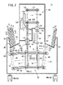
図1は、第1実施形態に係る放射線画像情報読取装置10の外観図、図2は、放射線画像情報読取装置10の内部構成図である。
【0019】
放射線画像情報読取装置10は、図3に示すカセッテ12に収納された蓄積性蛍光体シート14に記録された放射線画像情報を読み取った後、残存する放射線画像情報を消去し、カセッテ12に収納して排出する機能を備える。
【0020】
ここで、カセッテ12は、一端部に蓄積性蛍光体シート14を挿脱するための開口部16を有し、他端部の特定個所には、カセッテ12の放射線画像情報読取装置10に対する装填状態を検出するための反射マーカ18が配設される。また、カセッテ12の側面および開口部16寄りの正面には、当該カセッテ12のサイズや、収納される蓄積性蛍光体シート14を特定するための管理用の識別情報を記録したバーコード、ICチップ等の識別部20、22が配設される。さらに、カセッテ12の反射マーカ18寄りの正面には、蓄積性蛍光体シート14に記録された放射線画像情報に係る患者名、撮影部位等を表示するLCD等の表示部24が配設される。
【0021】
カセッテ12に収納される蓄積性蛍光体シート14は、例えば、ガラス等の硬質材料からなる支持基板26に柱状の蓄積性蛍光体層28を蒸着して形成される硬質のシートを用いることができる。なお、蓄積性蛍光体層28は、真空容器内で蓄積性蛍光体を加熱して蒸発させ、これらを支持基板26上に付着させる真空蒸着法、スパッタリング法、CVD、イオンフレーティング法を用いて形成することができる。このようにして形成される蓄積性蛍光体層28は、蓄積性蛍光体が蓄積性蛍光体シート14の平面と略垂直な柱状をなし、それぞれが光学的に独立に構成されており、照射される放射線に対して高感度で、且つ、画像の粒状性を低下させることができるとともに、励起光の散乱を減少させて画質を鮮明にすることができる。
【0022】
蓄積性蛍光体シート14の両側部には、係止用板ばね30a、30bが取着されており、蓄積性蛍光体シート14をカセッテ12に挿入した際、これらの係止用板ばね30a、30bがカセッテ12の孔部34a、34bに係止する。これにより、蓄積性蛍光体シート14をカセッテ12に固定保持させることができる。これらの孔部34a、34bにロック解除ピン(後述)を挿入することにより、蓄積性蛍光体シート14の係止を解除することができる。また、カセッテ12の反射マーカ18が配設される面の両端部には、カセッテ12から蓄積性蛍光体シート14を排出させるための排出ピン(後述)を挿入する孔部36a、36bが形成される。
【0023】
放射線画像情報読取装置10は、複数のカセッテ12を装填可能なカセッテ装填部38と、処理された複数のカセッテ12が排出されるカセッテ排出部40と、カセッテ12をカセッテ装填部38およびカセッテ排出部40間で搬送するカセッテ搬送部42(カセッテ処理部)と、カセッテ12から取り出された蓄積性蛍光体シート14に対する読取処理および消去処理を行う本体部44とを備える。カセッテ装填部38およびカセッテ排出部40は、本体部44の前部および後部に配設され、カセッテ搬送部42は、カセッテ装填部38、カセッテ排出部40および本体部44の下部に配設される。放射線画像情報読取装置10は、ケーシング46によって囲繞され、キャスタ48a〜48dを介して移動可能に構成される。なお、ケーシング46の側面には、放射線画像情報読取装置10の稼動状態を含む種々の情報を表示する表示部49が配設される。
【0024】
カセッテ装填部38は、種々のサイズからなる複数のカセッテ12を同時に装填可能な装填ボックス50を有する。装填ボックス50の底面部52は、図4に示すように、本体部44から離間する方向の下方向に傾斜し、最下部の底面部52には、カセッテ12を放射線画像情報読取装置10の内部に取り込む蓋部材54が配設される。なお、カセッテ12を保持する装填ボックス50の壁部51は、カセッテ12が安定した状態で装填されるよう、本体部44側から離間する方向に所定量傾斜して設定される。
【0025】
カセッテ装填部38の蓋部材54を含む底面部52には、装填されたカセッテ12の装填状態を検出する複数のセンサS11〜S54が配設される。センサS11〜S54は、カセッテ12の端部に配設された反射マーカ18による反射光の有無を検出する。この場合、センサS11〜S14は、蓋部材54に沿って後述する所定間隔で配設され、蓋部材54上に装填されたカセッテ12の装填状態を検出する。また、センサS21〜S24、S31〜S34、S41〜S44およびS51〜S54の各組は、蓋部材54上に装填されたカセッテ12に対して並べて装填された各カセッテ12の装填状態を検出する。
【0026】
蓋部材54は、センサS11〜S14によって検出されたカセッテ12の装填状態が正常である場合、蓋開閉モータ56によって開成し、カセッテ12を放射線画像情報読取装置10の内部に取り込む。一方、カセッテ装填部38の側部には、図1に示すように、各カセッテ12が装填される位置に対応して、装填されているカセッテ12の装填状態を示す表示部58a〜58eが配設される。図5は、カセッテ12の装填状態を検出して処理する検出処理回路を示す。検出処理回路は、センサS11〜S54により検出したカセッテ12の装填状態を判定する判定部60を有する。判定部60は、判定結果に基づき、表示部58a〜58eにカセッテ12の装填状態を表示するとともに、蓋開閉モータ56を駆動して蓋部材54の開閉制御を行う。
【0027】
カセッテ搬送部42は、カセッテ12を保持する第1処理機構62および第2処理機構64を有し、カセッテ12をその面と略直交する方向に搬送する。第1処理機構62は、上下に配設されたガイド部材66、68にガイドされ、カセッテ装填部38の下部の第1処理部70から第2処理部72を介して第3処理部74までの間を往復動作可能に構成される。また、第2処理機構64は、ガイド部材66、68にガイドされ、第3処理部74とカセッテ排出部40の下部の第4処理部76との間を往復動作可能に構成される。
【0028】
第1処理機構62は、図6に示すように、上下部が支軸78、80を介してガイド部材66、68のガイド溝82、84に移動可能に支持される。第1処理機構62は、カセッテ装填部38からニップローラ86によって供給されたカセッテ12の下端部を支持する支持部材88a、88bを有する。支持部材88a、88bには、カセッテ12の端部に形成された孔部36a、36bに挿入されることで、蓄積性蛍光体シート14をカセッテ12から排出する排出ピン89a、89bを進退駆動するソレノイド91a、91bが配設される。また、第1処理機構62は、カセッテ装填部38から供給されるカセッテ12に配設された識別部22のバーコードやICチップに記録された当該カセッテ12のサイズ情報を読み取る読取部93を備える。
【0029】
支持部材88a、88bは、ソレノイド91a、91bとともに、第1処理機構62に沿って略鉛直方向に延在する連結板90a、90bに沿って上下方向に移動可能に構成される。各連結板90a、90bは、水平方向に延在するラック部材92a、92bを有し、これらのラック部材92a、92bにピニオンギア94が噛合する。連結板90a、90bの略中央部には、幅寄せ板96a、96bが配設されており、ピニオンギア94の回転によって連結板90a、90bが近接移動することにより、カセッテ12が第1処理機構62の中央部に幅寄せされる。
【0030】
連結板90a、90bの上端部には、カセッテ12の両側部に形成された孔部34a、34bに挿入されることで、蓄積性蛍光体シート14のカセッテ12に対するロック状態を解除するロック解除ピン98a、98bを進退駆動するソレノイド100a、100bが配設される。
【0031】
第2処理機構64は、第1処理機構62によって第3処理部74に搬送されたカセッテ12の両側部を把持するとともに、上下方向に移動可能な把持板102a、102bを有する。なお、把持板102a、102bは、第1処理機構62を構成する幅寄せ板96a、96bに干渉しない部位に配設されるものとする。
【0032】
カセッテ排出部40は、第4処理部76からニップローラ106により蓋部材108を介して排出された複数のカセッテ12を収容する収容ボックス110を有する。収容ボックス110は、カセッテ装填部38の装填ボックス50の場合と同様に、底面部112が傾斜して構成される。
【0033】
本体部44は、カセッテ搬送部42との間が隔壁114によって隔離され、且つ、蓄積性蛍光体シート14が出入する部位にシャッタ機構116、118が配設されることにより、光密な状態に保持される。シャッタ機構116、118は、例えば、蓄積性蛍光体シート14が出入する際に開閉されるシャッタ機構、あるいは、蓄積性蛍光体シート14に摺接する遮光部材を配設して構成することができる。なお、シャッタ機構116と第2処理部72との間には、蓄積性蛍光体シート14を本体部44に供給するニップローラ119が配設される。
【0034】
本体部44には、鉛直上方向に延在する直線状の読取搬送路120(往路搬送路)が配設される。読取搬送路120の略中央部には、読取搬送路120によって副走査方向に搬送される蓄積性蛍光体シート14に対して、レーザビームとしての励起光Lを主走査方向に照射する励起光走査部122が配設される。また、励起光Lによる主走査線に近接し、蓄積性蛍光体シート14から得られる輝尽発光光を集光する集光ガイド124の一端部が配設され、集光ガイド124の他端部には、輝尽発光光を電気信号に変換するフォトマルチプライア等からなる光電変換部126(読取部)が配設される。
【0035】
読取搬送路120の上部には、放射線画像情報が読み取られた蓄積性蛍光体シート14を略水平方向に搬送するシート搬送部128が配設される。シート搬送部128は、ガイド部材130、132にガイドされ、水平方向に移動可能に構成される上下一対のニップローラ134、136を有する。
【0036】
カセッテ排出部40側に移動したシート搬送部128の下部には、シャッタ機構118が配設される。そして、シャッタ機構118と、カセッテ搬送部42の第3処理部74との間には、蓄積性蛍光体シート14に残存する放射線画像情報を消去する消去ユニット138(消去部)が配設される。消去ユニット138は、ハロゲンランプ等の消去光を出力する複数の光源を有する。なお、消去ユニット138の上下には、蓄積性蛍光体シート14を本体部44からカセッテ搬送部42に供給するための復路搬送路を構成するニップローラ140、142が配設される。
【0037】
ここで、カセッテ装填部38とカセッテ搬送部42の第1処理部70との間のニップローラ86に近接した部位には、カセッテ装填部38から供給されるカセッテ12の外面に付着した塵を除去するための塵除去機構144が配設される。塵除去機構144は、図7に示すように、支持体146a、146bに植設されて対向し、先端部同士が重畳するブラシ148a、148bを備える。ブラシ148a、148bは、カセッテ12の供給方向と直交する方向に延在して配設され、ブラシ148a、148b間を通過するカセッテ12の外面に当接する。なお、ブラシ148a、148bは、カセッテ12の静電気を除去する導電性材料により構成すると好適である。
【0038】
また、カセッテ搬送部42の第2処理部72と本体部44との間のニップローラ119に近接した部位には、第2処理部72から供給される蓄積性蛍光体シート14の外面に付着した塵を除去するための第2塵除去機構150が配設される。第2塵除去機構150は、塵除去機構144と同一に構成される。
【0039】
第1実施形態に係る放射線画像情報読取装置10は、基本的には以上のように構成されるものであり、次にその動作について説明する。
【0040】
先ず、作業者は、放射線画像情報が蓄積記録された蓄積性蛍光体シート14を収納するカセッテ12をカセッテ装填部38の装填ボックス50に装填する。この場合、装填ボックス50には、サイズの異なる複数のカセッテ12を同時に装填することができる。なお、本実施形態では、最大5つのカセッテ12を同時に装填可能であるものとする。
【0041】
カセッテ12が装填されると、装填ボックス50の底面部52に配設されたセンサS11〜S54が各カセッテ12の装填状態を検出する。判定部60(図5)は、センサS11〜S54からの検出情報に基づき、各カセッテ12の装填状態を判定し、その判定結果を表示部58a〜58eに表示するとともに、蓋開閉モータ56を制御し、装填ボックス50の最下部に配設される蓋部材54の開閉を行う。
【0042】
そこで、図8〜図13に基づき、カセッテ12の装填状態の判定方法を説明する。
【0043】
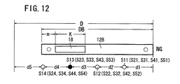
なお、カセッテ12は、幅DAからなる大サイズカセッテ12Aおよび幅DB(DA>DB)からなる小サイズカセッテ12Bの2種類があるものとし、装填ボックス50の幅Dが大サイズカセッテ12Aの幅DAに略等しく設定されているものとする。また、各大サイズカセッテ12A、小サイズカセッテ12Bの端部に配設される反射マーカ18は、幅Kからなり、それぞれ大サイズカセッテ12A、小サイズカセッテ12Bの側部から距離mの位置に配設されるものとする。さらに、装填ボックス50の底面部52に配設されるセンサS11〜S54は、装填ボックス50の両側部と相互の間隔が表示部58a〜58e側から距離d1〜d5に設定されているものとする。
【0044】
図8は、大サイズカセッテ12Aを識別部22等が手前となるようにし、且つ、蓄積性蛍光体シート14を挿入する開口部16が上部となるようにして装填ボックス50に装填した状態を示す。この場合、m<d1<m+K<d1+d2の関係に設定されていれば、センサS11(S21、S31、S41、S51)のみが反射マーカ18を検出する。従って、判定部60は、大サイズカセッテ12Aの装填状態が正常であると判定し、大サイズカセッテ12Aが装填されている装填ボックス50の位置に対応する表示部58a〜58eを、例えば、緑色に点灯させることで正常な装填状態を表す判定結果を表示する。
【0045】
図9は、大サイズカセッテ12Aを識別部22等が本体部44側となるようにして装填ボックス50に装填した状態を示す。この場合、m<d5<m+K<d5+d4の関係に設定されていれば、センサS14(S24、S34、S44、S54)のみが反射マーカ18を検出する。従って、判定部60は、大サイズカセッテ12Aの装填状態が異常であると判定し、大サイズカセッテ12Aが装填されている装填ボックス50の位置に対応する表示部58a〜58eを、例えば、赤色に点灯させることで異常な装填状態を表す判定結果を表示する。
【0046】
図10は、小サイズカセッテ12Bを識別部22等が手前となるようにし、表示部58a〜58e側に寄せた状態で装填ボックス50に装填した状態を示す。この場合、図8に示す大サイズカセッテ12Aと同様に、装填状態が正常である判定結果を表示部58a〜58eによって知ることができる。
【0047】
図11は、小サイズカセッテ12Bを識別部22等が手前となるようにし、且つ、表示部58a〜58eから離間させた状態で装填ボックス50に装填した状態を示す。この場合、D−DB+m<d1+d2<D−DB+m+K<d1+d2+d3の関係に設定されていれば、センサS12(S22、S32、S42、S52)のみが反射マーカ18を検出する。従って、判定部60は、小サイズカセッテ12Bの装填状態が正常であると判定し、小サイズカセッテ12Bが装填されている装填ボックス50の位置に対応する表示部58a〜58eを、例えば、緑色に点灯させることで正常な装填状態を表す判定結果を表示する。
【0048】
なお、反射マーカ18の幅Kをd2<Kとなる所定幅とし、センサS11(S21、S31、S41、S51)またはS12(S22、S32、S42、S52)の少なくとも一方が反射マーカ18を検出できるように設定すれば、小サイズカセッテ12Bを装填ボックス50の任意の位置に装填した場合であっても、装填状態が正常であることを確実に検出することができる。
【0049】
図12は、小サイズカセッテ12Bを識別部22等が本体部44側となるようにし、表示部58a〜58e側に寄せた状態で装填ボックス50に装填した状態を示す。この場合、D−DB+m<d5+d4<D−DB+m+K<d5+d4+d3の関係に設定されていれば、センサS13(S23、S33、S43、S53)のみが反射マーカ18を検出する。従って、判定部60は、小サイズカセッテ12Bの装填状態が異常であると判定し、小サイズカセッテ12Bが装填されている装填ボックス50の位置に対応する表示部58a〜58eを、例えば、赤色に点灯させることで異常な装填状態を表す判定結果を表示する。
【0050】
図13は、小サイズカセッテ12Bを識別部22等が手前となるようにし、且つ、表示部58a〜58eから離間させた状態で装填ボックス50に装填した状態を示す。この場合、m<d5<m+K<d5+d4の関係に設定されていれば、センサS14(S24、S34、S44、S54)のみが反射マーカ18を検出する。従って、判定部60は、小サイズカセッテ12Bの装填状態が異常であると判定し、小サイズカセッテ12Bが装填されている装填ボックス50の位置に対応する表示部58a〜58eを、例えば、赤色に点灯させることで異常な装填状態を表す判定結果を表示する。
【0051】
なお、反射マーカ18の幅Kをd4<Kとなる所定幅とし、センサS14(S24、S34、S44、S54)またはS13(S23、S33、S43、S53)の少なくとも一方が反射マーカ18を検出できるように設定すれば、小サイズカセッテ12Bを装填ボックス50の任意の位置に装填した場合であっても、装填状態が異常であることを確実に検出することができる。また、カセッテ12の上下あるいは縦横を間違えてカセッテ装填部38に装填した場合には、何れのセンサS11〜S54も反射マーカ18を検出することができないため、装填状態が異常であると判定することができる。
【0052】
ここで、上記の説明では、カセッテ12の装填状態を検出するため、反射マーカ18による反射光の有無をセンサS11〜S54によって検出するように構成しているが、例えば、反射マーカ18に代えて識別情報を含むバーコードをカセッテ12の特定個所に配設し、バーコードリーダでバーコードを読取可能か否かによって装填状態を検出することもできる。この場合、カセッテ12を表示部58a〜58e側に寄せた状態で装填することを制約条件としておけば、表示部58a〜58e側にのみ配設したバーコードリーダにより、カセッテ12の装填状態を検出することができる。また、レーザビームを広範囲にスキャンさせてバーコードを読み取る構成とすれば、装填ボックス50の任意の位置に装填されたカセッテ12の装填状態を検出することも可能である。
【0053】
さらに、装填状態の検出部としては、RFID(Radio Frequency Identification)、磁気センサ、渦電流検出センサ等を用いることもできる。この場合、例えば、ペースメーカ等の誤動作が惹起する懸念を払拭するため、患者に近接して使用されるカセッテ12側には、磁界を発生することのない金属部材を配設することが望ましい。
【0054】
さらにまた、マイクロスイッチ等の機械的な検出部を装填ボックス50側に配設し、その検出部をカセッテ12側に設けた凹部等の検出用部材が機械的に動作させるか否かによって装填状態を検出するように構成することもできる。
【0055】
なお、以上のようにして検出されたカセッテ12の装填状態に係る情報は、放射線画像情報読取装置10に接続される外部の装置、例えば、カセッテ12に記録される患者ID等を入力する端末装置に供給し、放射線画像情報読取装置10での処理状況を作業者に通知することもできる。
【0056】
作業者は、表示部58a〜58eに表示されたカセッテ12の装填状態を確認し、あるいは、放射線画像情報読取装置10から通知された装填状態に係る情報を確認し、異常な装填状態にあるカセッテ12の装填状態を纏めて修正することができる。従って、作業者は、複数のカセッテ12に対する装填状態を速やかに修正した後、放射線画像情報読取装置10から離れ、他の作業に移行することができる。
【0057】
一方、カセッテ装填部38は、蓋部材54上に装填されたカセッテ12の装填状態が正常であることが確認されると、蓋開閉モータ56を駆動して蓋部材54を回動し、カセッテ12を放射線画像情報読取装置10の内部に取り込む。この場合、カセッテ装填部38を構成する底面部52は、蓋部材54側が下となるように傾斜して設定されているため、カセッテ12は、自重によって順次蓋部材54側に移動した後、放射線画像情報読取装置10の内部に取り込まれる。
【0058】
取り込まれたカセッテ12は、ニップローラ86によって挟持搬送され、第1処理部70に待機する第1処理機構62に供給される。この場合、ニップローラ86の下部近傍には、図7に示す構成からなる塵除去機構144が配設されている。ニップローラ86によって搬送されたカセッテ12は、塵除去機構144を構成するブラシ148a、148b間を通過することにより、外面に付着している塵が除去されて第1処理機構62に供給される。ブラシ148a、148bを導電性材料により構成すれば、静電気によってカセッテ12に付着している塵を一層良好に除去することができる。なお、カセッテ12から除去され、放射線画像情報読取装置10の下部に落下した塵は、例えば、メンテナンス等の際に外部に排出させることが望ましい。
【0059】
塵除去機構144によって外面の塵が除去されたカセッテ12は、識別部22に記録されたサイズ情報が第1処理機構62の読取部93によって読み取られた後、下端部が支持部材88a、88bによって支持される(図6参照)。次いで、ピニオンギア94が回転することでラック部材92a、92bが変位し、幅寄せ板96a、96bが近接移動することにより、カセッテ12の幅方向の位置決めが行われる。
【0060】
このように、カセッテ12の幅方向の位置は、第1処理機構62が備える幅寄せ板96a、96bにより、放射線画像情報読取装置10の内部において自動的に調整される。従って、作業者は、装填位置を特別に意識することなく、カセッテ12をカセッテ装填部38に装填することができる。
【0061】
カセッテ12が幅寄せされた後、読取部93によって読み取られたサイズ情報に従い、支持部材88a、88bが連結板90a、90bに沿って上下方向に所定量変位し、カセッテ12の上下方向の位置決めが行われる。
【0062】
以上のようにしてカセッテ12の位置決めが行われた後、第1処理機構62は、ガイド部材66、68にガイドされた状態でカセッテ12を第2処理部72まで搬送する。次いで、第1処理機構62の上部に配設されたソレノイド100a、100bが駆動されることにより、ロック解除ピン98a、98bがカセッテ12の孔部34a、34bに挿入され、係止用板ばね30a、30bの係止が解除される。次に、第1処理機構62の支持部材88a、88bに配設されたソレノイド91a、91bが駆動されることにより、排出ピン89a、89bがカセッテ12の孔部36a、36bに挿入される。この結果、カセッテ12に収納された蓄積性蛍光体シート14が開口部16から上部に露出する。
【0063】
カセッテ12から排出された蓄積性蛍光体シート14の上端部は、第2塵除去機構150を介してニップローラ119により挟持され、シャッタ機構116から本体部44内に供給される。この場合、蓄積性蛍光体シート14の両面に付着した塵が第2塵除去機構150を構成するブラシによって除去される。なお、カセッテ12の塵を除去する塵除去機構144の場合と同様に、ブラシを導電性材料とすることにより、静電気によって蓄積性蛍光体シート14に付着している塵を一層良好に除去することができる。
【0064】
一方、蓄積性蛍光体シート14を本体部44に排出したカセッテ12を保持する第1処理機構62は、ガイド部材66、68にガイドされた状態で第3処理部74までカセッテ12を搬送する。第3処理部74には、把持板102a、102bを有する第2処理機構64が待機しており、把持板102a、102bがカセッテ12の両側部を把持した後、第2処理機構64の支持部材88a、88bが下方向に退避することにより、カセッテ12がガイド部材66、68に受け渡される。
【0065】
カセッテ12を保持した第2処理機構64は、第3処理部74において待機する。また、第1処理機構62は、第1処理部70まで移動し、カセッテ装填部38から供給される次のカセッテ12に対する処理を行う。
【0066】
本体部44に供給された蓄積性蛍光体シート14は、読取搬送路120によって上方向に副走査搬送されるとともに、励起光走査部122から出力される励起光Lによって主走査される。励起光Lが照射された蓄積性蛍光体シート14からは、蓄積記録された放射線画像情報に対応した輝尽発光光が出力される。この輝尽発光光は、集光ガイド124を介して光電変換部126に導かれ、電気信号に変換される。なお、蓄積性蛍光体シート14は、本体部44に供給される直前において、外面に付着する塵が第2塵除去機構150により除去されているため、塵の影響のない状態で放射線画像情報が高精度に読み取られる。
【0067】
放射線画像情報の読み取られた蓄積性蛍光体シート14は、上下部分がニップローラ134、136によって挟持され、ガイド部材130、132にガイドされた状態でシート搬送部128により水平方向に所定量変位する。次いで、ニップローラ134、136によりシャッタ機構118を介して下方向に搬送される。
【0068】
シャッタ機構118の下部には、消去ユニット138が配設されており、ニップローラ140、142によって下方向に挟持搬送される蓄積性蛍光体シート14は、消去ユニット138から消去光が照射されることにより、残存する放射線画像情報が消去される。消去処理が終了した蓄積性蛍光体シート14は、第3処理部74に待機するカセッテ12に開口部16から挿入される。
【0069】
蓄積性蛍光体シート14を収納したカセッテ12は、第2処理機構64によって第4処理部76まで搬送された後、把持板102a、102bにより把持された状態で上方向に変位する。次いで、カセッテ12は、上端部がニップローラ106により挟持され、蓋部材108を介してカセッテ排出部40の収容ボックス110に排出される。この場合、カセッテ排出部40を構成する底面部112は、蓋部材108から離間する側が下となるように傾斜して設定されているため、排出されたカセッテ12は、自重により移動して収容ボックス110内に積層される。
【0070】
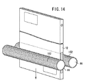
なお、上記の説明では、カセッテ12の塵を除去する塵除去機構144を図7に示すブラシ148a、148bによって構成したが、図14に示すように、カセッテ装填部38と第1処理部70との間に配設されるニップローラ86の外周面に粘着材料152を装着し、粘着材料152をカセッテ12の外面に当接させながら第1処理部70に供給することで塵を除去するようにしてもよい。この場合、塵除去機構とニップローラ86とを兼用することができる。
【0071】
また、蓄積性蛍光体シート14の塵を除去する第2塵除去機構150に代えて、シャッタ機構116を図15に示すように構成することにより、本体部44を遮光する遮光機構として機能させるとともに、第2塵除去機構としても機能させることができる。
【0072】
すなわち、このシャッタ機構116は、蓄積性蛍光体シート14が通過する通路109を形成する第1遮光部材121a、121bおよび第2遮光部材123a、123bと、シャッタ部材125とを備える。
【0073】
第1遮光部材121a、121bは、蓄積性蛍光体シート14の搬送方向と平行で互いに対向する面が蓄積性蛍光体シート14の厚味Wよりも僅かに離間して配設され、これらの面には、蓄積性蛍光体シート14の記録面である蓄積性蛍光体層28と、蓄積性蛍光体シート14の背面である支持基板26とに密着する導電性材料からなる植毛127a、127bが植設される。
【0074】
第2遮光部材123a、123bは、蓄積性蛍光体シート14の搬送方向と直交する方向に配設され、互いに対向する面を有し、これらの面には、蓄積性蛍光体シート14の幅方向の両側面に密着する導電性材料からなる植毛129a、129bが植設される。第2遮光部材123a、123bは、第2処理部72側の第1遮光部材121a、121bの下面部に配設され、変位手段131a、131bにより蓄積性蛍光体シート14の幅方向に変位可能に構成される。
【0075】
シャッタ部材125は、本体部44側の第1遮光部材121a、121bの上面部に配設され、回動手段133により回動することで通路109を開閉可能に構成される。この場合、シャッタ機構118による光密性をさらに確実なものとするため、第1遮光部材121a、121bに当接するシャッタ機構118に植毛を植設するようにしてもよい。
【0076】
シャッタ機構116をこのように構成した場合、ニップローラ119によって挟持搬送され、第2処理部72から供給された蓄積性蛍光体シート14は、先ず、上端部が第1遮光部材121a、121b間の通路109に挿入される。次いで、変位手段131a、131bが駆動され、第2遮光部材123a、123bが変位して蓄積性蛍光体シート14の両側部に当接する。
【0077】
この場合、蓄積性蛍光体シート14の蓄積性蛍光体層28には、第1遮光部材121aに植設された植毛127aが密着し、支持基板26には、第1遮光部材121bに植設された植毛127bが密着する。また、蓄積性蛍光体シート14の両側面には、第2遮光部材123a、123bに植設された植毛129a、129bが密着する。従って、蓄積性蛍光体シート14の蓄積性蛍光体層28側の面、支持基板26側の面および両側面に植毛127a、127b、129a、129bが密着した状態となるため、第2処理部72側から光が本体部44側に浸入することがない。
【0078】
次に、前記の状態から回動手段133が駆動され、シャッタ部材125が開成された後、蓄積性蛍光体シート14が本体部44内に供給される。このとき、蓄積性蛍光体シート14の外面には植毛127a、127b、129a、129bが密着しているため、蓄積性蛍光体シート14に付着した塵が確実に除去される。この結果、本体部44に供給された蓄積性蛍光体シート14は、塵のない状態で高精度に読取処理が行われる。
【0079】
図16は、第2実施形態に係る放射線画像情報読取装置160の外観図、図17は、放射線画像情報読取装置160の内部構成図である。なお、放射線画像情報読取装置10と同一の構成要素には、同一の参照符号を付し、その詳細な説明を省略する。
【0080】
放射線画像情報読取装置160は、複数のカセッテ12を装填可能なカセッテ装填部162と、処理された複数のカセッテ12が排出されるカセッテ排出部164と、カセッテ12に収納された蓄積性蛍光体シート14に対する読取処理および消去処理を行う本体部166と、カセッテ12をカセッテ装填部162から本体部166の下部、および、本体部166の下部からカセッテ排出部164に搬送するカセッテ搬送部168(カセッテ処理部)とを備える。
【0081】
カセッテ装填部162およびカセッテ排出部164は、本体部166の前部に隣接して配設される。カセッテ装填部162におけるカセッテ12を取り込む蓋部材54と、カセッテ排出部164におけるカセッテ12を排出する蓋部材108とには、シャッタ機構170、172が配設される。放射線画像情報読取装置160を構成する本体部166およびカセッテ搬送部168は、ケーシング174およびシャッタ機構170、172によって光密に保持される。
【0082】
カセッテ12を第1処理部176に供給するニップローラ86の近傍には、カセッテ12に付着した塵を除去する塵除去機構144が配設され、蓄積性蛍光体シート14を第3処理部180から本体部166に供給するニップローラ119の近傍には、蓄積性蛍光体シート14に付着した塵を除去する第2塵除去機構150が配設される。
【0083】
カセッテ搬送部168は、ガイド部材66、68を介して第1処理部176、第2処理部178および第3処理部180間を移動する保持機構62を有する。また、本体部166は、鉛直上方向に延在する直線状の搬送路182を有し、この搬送路182に沿って、第3処理部180側から消去ユニット138、励起光走査部122、集光ガイド124および光電変換部126が配列される。
【0084】
第2実施形態に係る放射線画像情報読取装置160は、基本的には以上のように構成されるものであり、次にその動作について説明する。
【0085】
作業者によってカセッテ装填部162に複数のカセッテ12が装填されると、各カセッテ12の装填状態がセンサS11〜S54(図4参照)等によって検出され、その判定結果がカセッテ装填部162の側部の表示部58a〜58eに表示される。作業者は、装填状態が異常であると判定されたカセッテ12の修正を行う。
【0086】
次いで、装填状態が正常であると判定されたカセッテ12は、カセッテ装填部162からカセッテ搬送部168の第1処理部176に供給される。この場合、ニップローラ86の下部に配設された塵除去機構144によってカセッテ12の外面に付着した塵が除去される。次いで、塵の除去されたカセッテ12は、第1処理機構62によって第3処理部180まで搬送される。
【0087】
次に、第3処理部180においてカセッテ12から取り出された蓄積性蛍光体シート14は、第2塵除去機構150を通過することにより外面に付着した塵が除去された後、ニップローラ119によって本体部166の搬送路182に供給され、上方向に副走査搬送されるとともに、励起光走査部122から出力される励起光Lによって主走査される。蓄積性蛍光体シート14から得られた輝尽発光光は、集光ガイド124を介して光電変換部126に導かれ、電気信号としての放射線画像情報に変換される。
【0088】
放射線画像情報の読み取られた蓄積性蛍光体シート14は、搬送路182によって下方向に搬送されるとともに、消去ユニット138から消去光が照射され、残存する放射線画像情報が消去される。
【0089】
放射線画像情報が消去された蓄積性蛍光体シート14は、第3処理部180に待機するカセッテ12に収納された後、第2処理部178に搬送され、次いで、カセッテ排出部164に排出される。
【0090】
図18は、第3実施形態に係る放射線画像情報読取装置190の内部構成図である。なお、放射線画像情報読取装置10または160と同一の構成要素には、同一の参照符号を付し、その詳細な説明を省略する。
【0091】
放射線画像情報読取装置190は、本体部192と、本体部192の前後に配設され、複数のカセッテ12を装填可能なカセッテ装填部38およびカセッテ排出部40と、カセッテ12を第1処理部176、第2処理部178および第3処理部180間で搬送するカセッテ搬送部168(カセッテ処理部)とを有する。
【0092】
第1処理部176は、カセッテ装填部38の下部に配設され、第2処理部178は、本体部192の下部に配設され、第3処理部180は、カセッテ排出部40の下部に配設される。本体部192は、放射線画像情報読取装置190を構成するケーシング174と隔壁194とによって光密に構成され、隔壁194には、シャッタ機構196が配設される。消去ユニット138は、シャッタ機構196と第2処理部178との間に配設される。
【0093】
カセッテ12を第1処理部176に供給するニップローラ86の近傍には、カセッテ12に付着した塵を除去する塵除去機構144が配設され、蓄積性蛍光体シート14を第2処理部178から消去ユニット138を介して本体部192に供給するニップローラ142の近傍には、蓄積性蛍光体シート14に付着した塵を除去する第2塵除去機構150が配設される。
【0094】
第3実施形態に係る放射線画像情報読取装置190は、基本的には以上のように構成されるものであり、次にその動作について説明する。
【0095】
作業者によってカセッテ装填部38に複数のカセッテ12が装填され、装填状態が正常であると判定されたカセッテ12は、塵除去機構144を介してカセッテ搬送部168の第1処理部176に供給される。このとき、カセッテ12の外面に付着した塵が塵除去機構144によって除去される。次いで、塵の除去されたカセッテ12は、第1処理機構62により第2処理部178まで搬送される。
【0096】
次に、第2処理部178においてカセッテ12から取り出された蓄積性蛍光体シート14は、第2塵除去機構150を通過することにより外面に付着した塵が除去された後、ニップローラ142、140、シャッタ機構196を介して本体部192に供給され、搬送路182によって放射線画像情報読取装置190の上部まで搬送された後、下方向に搬送され、放射線画像情報の読み取りが行われる。読み取りが完了した蓄積性蛍光体シート14の下端部は、シャッタ機構196を介して消去ユニット138側に搬出され、残存する放射線画像情報の消去処理が行われる。従って、蓄積性蛍光体シート14は、光電変換部126による放射線画像情報の読取処理と、消去ユニット138による消去処理とを同時に行うことができる。
【0097】
一方、消去ユニット138の下部の第2処理部178には、カセッテ12が待機しており、読取処理および消去処理が完了した蓄積性蛍光体シート14がカセッテ12に挿入されると、第1処理機構62が第3処理部180に移動し、次いで、カセッテ12がカセッテ排出部40に排出される。
【0098】
図19は、第4実施形態に係る放射線画像情報読取装置200の内部構成図である。なお、放射線画像情報読取装置190と同一の構成要素には、同一の参照符号を付し、その詳細な説明を省略する。
【0099】
放射線画像情報読取装置200を構成するカセッテ搬送部168は、カセッテ12を第1処理部176から第2処理部178に搬送処理する第1処理機構62と、カセッテ12を第2処理部178から第3処理部180に搬送処理する第2処理機構64とを備える。
【0100】
第1処理機構62は、カセッテ装填部38から塵除去機構144を介して供給されたカセッテ12を、第1処理部176から第2処理部178に搬送した後、蓄積性蛍光体シート14を取り出し、第2塵除去機構150を介して本体部192に供給する。蓄積性蛍光体シート14を本体部192に供給したカセッテ12は、第1処理機構62から第2処理機構64に受け渡され、第2処理部178に待機する。また、第1処理機構62は、次のカセッテ12を受け取るため、第1処理部176まで移動する。
【0101】
本体部192での処理が終了した蓄積性蛍光体シート14は、消去ユニット138により残存する放射線画像情報が消去されるとともに、第2処理部178に待機するカセッテ12に収納される。次いで、第2処理機構64によって第3処理部180に移動した後、カセッテ排出部40に排出される。
【0102】
このように、第4実施形態の放射線画像情報読取装置200では、第1処理機構62によってカセッテ12をカセッテ装填部38から受け取って本体部192に供給する処理と、第2処理機構64によってカセッテ12を第3処理部180からカセッテ排出部40に排出する処理とを並行して効率的に行うことができる。
【0103】
なお、放射線画像情報読取装置160、190、200において、塵除去機構144を図14に示す粘着材料152の装着されたニップローラ86として構成することもできる。
【0104】
また、上述した各実施形態では、端部に開口部16を有し、この開口部16より蓄積性蛍光体シート14を挿脱する構成からなるカセッテ12を用いているが、例えば、蓋部材を開閉することで蓄積性蛍光体シート14を挿脱できる構成としたカセッテや、蓄積性蛍光体シート14における放射線画像情報の記録面に対して着脱自在な保護カバーを装着した一体型のカセッテに対しても同様に適用できることは勿論である。
【0105】
また、カセッテ12に収納される蓄積性蛍光体シート14としては、硬質材料からなる支持基板26上に蓄積性蛍光体層28を形成したものに限られるものではなく、蓄積性蛍光体をフレキシブルな支持基板に塗布してなる蓄積性蛍光体シートを利用することもできる。
【0106】
さらに、上述した各実施形態では、カセッテ装填部38、162の底面部52およびカセッテ排出部40、164の底面部112を傾斜させることにより、カセッテ12の自重を利用して所定部位まで移動させるように構成しているが、カセッテ移動機構を用いてカセッテ12を移動させるように構成することもできる。
【0107】
例えば、カセッテ装填部38、162では、モータ等の駆動源あるいはスプリング等の弾性部材を用いて壁部を蓋部材54側に移動可能に構成することにより、カセッテ12を順次蓋部材54側に移動させることができる。また、カセッテ排出部40、164では、モータ等の駆動源によって壁部を移動させることにより、蓋部材108を介して排出されたカセッテ12を順次所定部位まで移動させることができる。このように構成することにより、底面部52、112を傾斜させることなく、カセッテ12を所定部位まで移動させることが可能となる。
【0108】
【発明の効果】
以上のように、本発明の放射線画像情報読取装置では、外面に付着した塵を塵除去機構によって除去した状態で装置内にカセッテを供給するため、塵の影響によって装置の動作不良等が発生する事態を回避することができる。また、カセッテに付着した塵が蓄積性蛍光体シートに付着することもないため、放射線画像情報を高精度に読み取ることができる。さらに、塵除去機構を導電性材料からなるブラシとすることにより、カセッテまたは蓄積性蛍光体シートを除電して塵を一層確実に除去することができる。
【0109】
なお、カセッテの外面から塵を除去する塵除去機構を装置内を光密に保持するための遮光機構に配設し、あるいは、蓄積性蛍光体シートの外面から塵を除去する第2塵除去機構を読取部を光密に保持する遮光機構に配設することにより、機構を一体化して省スペース化を図ることができる。この結果、放射線画像情報読取装置の小型化を容易に達成することができる。
【図面の簡単な説明】
【図1】第1実施形態に係る放射線画像情報読取装置の外観図である。
【図2】第1実施形態に係る放射線画像情報読取装置の内部構成図である。
【図3】第1実施形態に係る放射線画像情報読取装置に装填されるカセッテの構成図である。
【図4】第1実施形態に係る放射線画像情報読取装置におけるカセッテ装填部の一部断面構成図である。
【図5】第1実施形態に係る放射線画像情報読取装置における装填状態の検出処理回路のブロック図である。
【図6】第1実施形態に係る放射線画像情報読取装置における第1処理機構の説明図である。
【図7】第1実施形態に係る放射線画像情報読取装置における塵除去機構の構成説明図である。
【図8】第1実施形態に係る放射線画像情報読取装置におけるカセッテ装填部での装填状態検出処理の説明図である。
【図9】第1実施形態に係る放射線画像情報読取装置におけるカセッテ装填部での装填状態検出処理の説明図である。
【図10】第1実施形態に係る放射線画像情報読取装置におけるカセッテ装填部での装填状態検出処理の説明図である。
【図11】第1実施形態に係る放射線画像情報読取装置におけるカセッテ装填部での装填状態検出処理の説明図である。
【図12】第1実施形態に係る放射線画像情報読取装置におけるカセッテ装填部での装填状態検出処理の説明図である。
【図13】第1実施形態に係る放射線画像情報読取装置におけるカセッテ装填部での装填状態検出処理の説明図である。
【図14】塵除去機構の他の構成の説明図である。
【図15】塵除去機構と遮光機構とを一体化した構成の説明図である。
【図16】第2実施形態に係る放射線画像情報読取装置の外観図である。
【図17】第2実施形態に係る放射線画像情報読取装置の内部構成図である。
【図18】第3実施形態に係る放射線画像情報読取装置の内部構成図である。
【図19】第4実施形態に係る放射線画像情報読取装置の内部構成図である。
【符号の説明】
10、160、190、200…放射線画像情報読取装置
12…カセッテ 14…蓄積性蛍光体シート
38、162…カセッテ装填部 40、164…カセッテ排出部
42、168…カセッテ搬送部 44、166、192…本体部
62…第1処理機構 64…第2処理機構
70、176…第1処理部 72、178…第2処理部
74、180…第3処理部 76…第4処理部
116、118、170、172、196…シャッタ機構
122…励起光走査部 126…光電変換部
138…消去ユニット 144…塵除去機構
150…第2塵除去機構 S11〜S54…センサ[0001]
BACKGROUND OF THE INVENTION
The present invention relates to a radiation configured to remove the stimulable phosphor sheet from the cassette supplied from the cassette loading unit, erase the remaining radiation image information after reading the radiation image information stored and recorded on the sheet. The present invention relates to an image information reading apparatus.
[0002]
[Prior art]
Conventionally, radiation images using a stimulable phosphor sheet that accumulates part of the irradiated radiation energy and emits stimulating light according to the accumulated radiation energy by irradiating excitation light such as visible light. Information reading devices are known.
[0003]
The radiological image information reader includes, for example, a cassette loading unit in which a cassette holding a stimulable phosphor sheet in which radiographic image information of a subject such as a human body is accumulated and loaded, and an accumulation property that is supplied after being detached from the cassette. A reading unit that irradiates the phosphor sheet with excitation light and reads the radiation image information; and an erasing unit that erases the remaining radiation image information by irradiating the storable phosphor sheet from which the radiation image information has been read; The storage phosphor sheet that has been subjected to the erasing process is configured to include a cassette discharge unit that holds and discharges the stimulable phosphor sheet (see, for example, Patent Documents 1 to 3).
[0004]
In Patent Document 1, after the cassette is taken into the apparatus from the cassette insertion slot, the stimulable phosphor sheet is detached from the cassette and supplied to the reading means and the erasing means to perform the processing, and the cassette is again stimulated. The phosphor sheet is held and discharged from the cassette discharge port.
[0005]
In Patent Document 2, the cassette loaded in the cassette receiving station is transferred to the separation station, and then the separated substrate of the lid is supplied to the scanning station and the erasing station for processing. Are recombined and discharged to the output station.
[0006]
In Patent Document 3, the cassette is transferred from the cassette introduction station to the cassette transfer station, and after the image plate taken out from the cassette is supplied to the reading device and the erasing device and processed, the cassette moving station is rotated. The processed image plate is accommodated in the waiting cassette and is extracted from the cassette extraction station.
[0007]
In the prior art described in these Patent Documents 1 to 3, since the cassette (cassette) itself is taken into the apparatus and processed, if dust adheres to the cassette (cassette), the dust will enter the apparatus. There are concerns about problems such as intrusion, malfunctions, and inability to read radiation image information with high accuracy.
[0008]
On the other hand, Patent Document 4 discloses a conventional technique configured to remove dust and the like by bringing a cleaning roller into contact with a stimulable phosphor sheet taken out from a cassette and then transporting it to a reading unit. ing. According to this prior art, since dust is suitably removed from the stimulable phosphor sheet, radiographic image information can be read with high accuracy.
[0009]
[Patent Document 1]
JP 2002-156716 A (FIG. 6)
[Patent Document 2]
JP-A-6-43565 (FIGS. 2 and 3)
[Patent Document 3]
Japanese translation of PCT publication No. 2001-503880 (FIG. 2)
[Patent Document 4]
Japanese Patent Laid-Open No. 5-72656 (FIG. 1)
[0010]
[Problems to be solved by the invention]
However, the conventional technique disclosed in Patent Document 4 can remove dust from the stimulable phosphor sheet immediately before being supplied to the reading unit, but it can remove dust attached to the cassette that houses the stimulable phosphor sheet. It cannot be removed. Therefore, in the case of a configuration in which a cassette (cassette) is taken into the apparatus as in Patent Documents 1 to 3, dust attached to the cassette (cassette) may enter the apparatus and cause malfunction. In particular, since the cassette (cassette) is likely to be left in a place where a lot of dust exists, there is a possibility that dust attached to the outer surface may enter the apparatus.
[0011]
The present invention has been made in view of the above problems, and provides a radiological image information reading apparatus capable of appropriately avoiding the intrusion of dust to eliminate the occurrence of malfunction of the apparatus and reading radiographic image information with high accuracy. The purpose is to provide.
[0012]
[Means for Solving the Problems]
In order to achieve the above object, the present invention provides a cassette loading unit in which a cassette for storing a stimulable phosphor sheet in which radiation image information is accumulated and recorded, and excitation light for the stimulable phosphor sheet. And reading out the photostimulated luminescence light obtained by photoelectrically reading the radiation image information, taking in the cassette from the cassette loading unit, and removing the stimulable phosphor sheet from the cassette In the radiographic image information reading apparatus, comprising: a cassette processing unit that is supplied to the reading unit; and an erasing unit that erases the remaining radiographic image information by irradiating the stimulable phosphor sheet with erasing light.
A dust removing mechanism is provided between the cassette loading unit and the cassette processing unit to contact the outer surface of the cassette taken in by the cassette processing unit and remove dust adhering to the outer surface. And
[0013]
In this case, when the cassette is taken into the apparatus from the cassette loading unit, the dust removing mechanism comes into contact with the outer surface of the cassette to remove the dust. The cassette processing unit removes the stimulable phosphor sheet from the cassette from which dust has been removed and supplies it to the reading unit. Therefore, it is possible to avoid a situation where dust enters the apparatus, and dust attached to the cassette does not adhere to the stimulable phosphor sheet.
[0014]
Here, when the cassette is loaded upright with respect to the cassette loading unit and configured to be supplied to the lower cassette processing unit, the area occupied by the radiation image information reading device can be reduced, and the size can be reduced. Although the possibility of dust intrusion from the upper portion is increased, dust entering from the upper portion together with the cassette is preferably removed by the dust removal mechanism, so that there is no possibility of hindering the operation of the apparatus or the like.
[0015]
In addition, as a dust removal mechanism, the brush and adhesive roller which remove dust by contact | abutting on the outer surface of a cassette can be used. If the brush is made of a conductive material, dust adhering to the cassette due to static electricity can be easily removed.
[0016]
Further, a dust removing mechanism for removing dust from the cassette is provided, and a second dust removing mechanism for removing dust by contacting the outer surface of the stimulable phosphor sheet detached from the cassette is provided between the cassette processing unit and the reading unit. Since the dust attached to the stimulable phosphor sheet can be removed, the radiation image information recorded on the stimulable phosphor sheet will not only cause malfunction of the apparatus. Can be read with high accuracy.
[0017]
By disposing the second dust removing mechanism in a light shielding mechanism that holds the reading unit in a light-tight manner, it is possible to avoid an increase in the size of the radiation image information reading device. The light-shielding mechanism can be configured by flocking that contacts the outer surface of the stimulable phosphor sheet to hold the reading unit in a light-tight manner and remove dust adhering to the stimulable phosphor sheet. . In addition, in a device in which a light shielding mechanism is disposed between the cassette loading unit and the cassette processing unit and the entire structure is light-tight, a dust removal mechanism for the cassette is disposed in the light shielding mechanism, thereby reducing the size of the device. It can also be made.
[0018]
DETAILED DESCRIPTION OF THE INVENTION
FIG. 1 is an external view of the radiation image
[0019]
The radiographic
[0020]
Here, the
[0021]
As the
[0022]
Locking
[0023]
The radiographic image
[0024]
The
[0025]
A plurality of sensors S <b> 11 to S <b> 54 for detecting the loaded state of the loaded
[0026]
When the loading state of the
[0027]
The
[0028]
As shown in FIG. 6, the upper and lower portions of the
[0029]
The
[0030]
An unlocking pin for releasing the locked state of the
[0031]
The
[0032]
The
[0033]
The
[0034]
The
[0035]
Above the reading conveyance path 120, a
[0036]
A
[0037]
Here, the dust adhering to the outer surface of the
[0038]
Further, dust adhering to the outer surface of the
[0039]
The radiation image
[0040]
First, the operator loads the
[0041]
When the
[0042]
Accordingly, a method for determining the loading state of the
[0043]
The
[0044]
FIG. 8 shows a state in which the large-
[0045]
FIG. 9 shows a state in which the large-
[0046]
FIG. 10 shows a state in which the small-
[0047]
FIG. 11 shows a state in which the small-
[0048]
The width K of the
[0049]
FIG. 12 shows a state in which the small-
[0050]
FIG. 13 shows a state in which the small-
[0051]
The width K of the
[0052]
Here, in the above description, in order to detect the loading state of the
[0053]
Furthermore, as a detection unit for a loaded state, an RFID (Radio Frequency Identification), a magnetic sensor, an eddy current detection sensor, or the like can be used. In this case, for example, it is desirable to dispose a metal member that does not generate a magnetic field on the side of the
[0054]
Furthermore, a mechanical detection unit such as a micro switch is provided on the
[0055]
The information relating to the loading state of the
[0056]
The operator confirms the loading state of the
[0057]
On the other hand, when it is confirmed that the loading state of the
[0058]
The taken-in
[0059]
The
[0060]
As described above, the position of the
[0061]
After the
[0062]
After the
[0063]
The upper end portion of the
[0064]
On the other hand, the
[0065]
The
[0066]
The
[0067]
The
[0068]
An erasing
[0069]
The
[0070]
In the above description, the
[0071]
Further, in place of the second
[0072]
That is, the
[0073]
The first
[0074]
The second
[0075]
The
[0076]
When the
[0077]
In this case, the
[0078]
Next, after the rotation means 133 is driven from the above state and the
[0079]
FIG. 16 is an external view of the radiation image
[0080]
The radiation image
[0081]
The
[0082]
In the vicinity of the
[0083]
The
[0084]
The radiation image
[0085]
When a plurality of
[0086]
Next, the
[0087]
Next, the
[0088]
The
[0089]
The
[0090]
FIG. 18 is an internal configuration diagram of the radiation image
[0091]
The radiographic image
[0092]
The
[0093]
In the vicinity of the
[0094]
The radiation image
[0095]
A plurality of
[0096]
Next, the
[0097]
On the other hand, in the
[0098]
FIG. 19 is an internal configuration diagram of the radiation image
[0099]
The
[0100]
The
[0101]
The
[0102]
As described above, in the radiation image
[0103]
In the radiation image
[0104]
Moreover, in each embodiment mentioned above, although it has the
[0105]
Further, the
[0106]
Further, in each of the above-described embodiments, the
[0107]
For example, in the
[0108]
【The invention's effect】
As described above, in the radiological image information reading apparatus according to the present invention, since the cassette is supplied into the apparatus in a state where the dust attached to the outer surface is removed by the dust removing mechanism, the apparatus malfunctions due to the influence of the dust. The situation can be avoided. Moreover, since the dust adhering to the cassette does not adhere to the stimulable phosphor sheet, the radiation image information can be read with high accuracy. Furthermore, by using a brush made of a conductive material as the dust removal mechanism, the cassette or the storage phosphor sheet can be neutralized to remove dust more reliably.
[0109]
A dust removing mechanism for removing dust from the outer surface of the cassette is disposed in a light shielding mechanism for holding the inside of the apparatus in a light-tight manner, or a second dust removing mechanism for removing dust from the outer surface of the stimulable phosphor sheet. Is arranged in a light-shielding mechanism that holds the reading unit in a light-tight manner, so that the mechanism can be integrated to save space. As a result, downsizing of the radiation image information reading apparatus can be easily achieved.
[Brief description of the drawings]
FIG. 1 is an external view of a radiation image information reading apparatus according to a first embodiment.
FIG. 2 is an internal configuration diagram of the radiation image information reading apparatus according to the first embodiment.
FIG. 3 is a configuration diagram of a cassette loaded in the radiation image information reading apparatus according to the first embodiment.
FIG. 4 is a partial cross-sectional configuration diagram of a cassette loading unit in the radiation image information reading apparatus according to the first embodiment.
FIG. 5 is a block diagram of a loading state detection processing circuit in the radiation image information reading apparatus according to the first embodiment.
FIG. 6 is an explanatory diagram of a first processing mechanism in the radiation image information reading apparatus according to the first embodiment.
7 is a configuration explanatory diagram of a dust removal mechanism in the radiation image information reading apparatus according to the first embodiment. FIG.
FIG. 8 is an explanatory diagram of a loading state detection process in a cassette loading unit in the radiation image information reading apparatus according to the first embodiment.
FIG. 9 is an explanatory diagram of a loading state detection process in a cassette loading unit in the radiation image information reading apparatus according to the first embodiment.
FIG. 10 is an explanatory diagram of a loading state detection process in a cassette loading unit in the radiation image information reading apparatus according to the first embodiment.
FIG. 11 is an explanatory diagram of a loading state detection process in a cassette loading unit in the radiation image information reading apparatus according to the first embodiment.
12 is an explanatory diagram of a loading state detection process in a cassette loading unit in the radiation image information reading apparatus according to the first embodiment. FIG.
FIG. 13 is an explanatory diagram of a loading state detection process in a cassette loading unit in the radiation image information reading apparatus according to the first embodiment.
FIG. 14 is an explanatory diagram of another configuration of the dust removal mechanism.
FIG. 15 is an explanatory diagram of a configuration in which a dust removal mechanism and a light shielding mechanism are integrated.
FIG. 16 is an external view of a radiation image information reading apparatus according to a second embodiment.
FIG. 17 is an internal configuration diagram of a radiation image information reading apparatus according to a second embodiment.
FIG. 18 is an internal configuration diagram of a radiation image information reading apparatus according to a third embodiment.
FIG. 19 is an internal configuration diagram of a radiation image information reading apparatus according to a fourth embodiment.
[Explanation of symbols]
10, 160, 190, 200 ... Radiation image information reading device
12 ...
38, 162 ...
42, 168 ...
62 ...
70, 176 ...
74, 180 ...
116, 118, 170, 172, 196 ... shutter mechanism
122 ... Excitation
138 ... Erasing
150 ... second dust removal mechanism S11-S54 ... sensor
Claims (11)
前記カセッテ装填部と前記カセッテ処理部との間には、前記カセッテ処理部により取り込まれる前記カセッテの外面に当接し、前記外面に付着する塵を除去する塵除去機構が配設されることを特徴とする放射線画像情報読取装置。A cassette loading unit in which a cassette for storing a stimulable phosphor sheet in which radiation image information is stored and recorded is irradiated, and the stimulable phosphor sheet is irradiated with excitation light, and the resulting photostimulated light is photoelectrically emitted. A reading unit that obtains the radiological image information by automatically reading, a cassette processing unit that takes in the cassette from the cassette loading unit, detaches the stimulable phosphor sheet from the cassette, and supplies it to the reading unit; In a radiation image information reading apparatus having an erasing unit that erases radiation image information remaining by irradiating the stimulable phosphor sheet with erasing light,
A dust removing mechanism is provided between the cassette loading unit and the cassette processing unit to contact the outer surface of the cassette taken in by the cassette processing unit and remove dust adhering to the outer surface. Radiation image information reading device.
前記カセッテ装填部には、前記カセッテが立設状態で装填され、前記カセッテが前記カセッテ装填部から下部の前記カセッテ処理部に搬送されて供給されることを特徴とする放射線画像情報読取装置。The apparatus of claim 1.
The radiographic image information reading apparatus according to claim 1, wherein the cassette is loaded in an upright state in the cassette loading section, and the cassette is transported from the cassette loading section to the cassette processing section below.
前記塵除去機構は、前記カセッテの外面に当接するブラシからなることを特徴とする放射線画像情報読取装置。The apparatus according to claim 1 or 2,
The radiographic image information reading apparatus according to claim 1, wherein the dust removing mechanism includes a brush that contacts an outer surface of the cassette.
前記ブラシは、導電性材料により構成されることを特徴とする放射線画像情報読取装置。The apparatus of claim 3.
The radiographic image information reading apparatus, wherein the brush is made of a conductive material.
前記塵除去機構は、前記カセッテの外面に当接する粘着ローラからなることを特徴とする放射線画像情報読取装置。The apparatus according to claim 1 or 2,
The radiographic image information reading apparatus, wherein the dust removing mechanism includes an adhesive roller that abuts on an outer surface of the cassette.
前記カセッテ処理部と前記読取部との間には、前記カセッテから離脱された前記蓄積性蛍光体シートの外面に当接し、前記外面に付着する塵を除去する第2塵除去機構が配設されることを特徴とする放射線画像情報読取装置。The apparatus of claim 1.
Between the cassette processing unit and the reading unit, a second dust removing mechanism that contacts the outer surface of the stimulable phosphor sheet detached from the cassette and removes dust adhering to the outer surface is disposed. A radiation image information reading apparatus.
前記カセッテ処理部と前記読取部との間には、前記読取部内を光密に保持する遮光機構が配設され、前記第2塵除去機構は、前記遮光機構に配設されることを特徴とする放射線画像情報読取装置。The apparatus of claim 6.
Between the cassette processing unit and the reading unit, a light shielding mechanism that holds the inside of the reading unit in a light-tight manner is disposed, and the second dust removing mechanism is disposed in the light shielding mechanism. A radiation image information reading device.
前記遮光機構は、前記蓄積性蛍光体シートの外面に当接することで、前記読取部を光密に保持するとともに前記蓄積性蛍光体シートに付着した塵を除去する植毛からなることを特徴とする放射線画像情報読取装置。The apparatus of claim 7.
The light-shielding mechanism includes flocking that contacts the outer surface of the stimulable phosphor sheet to hold the reading unit in a light-tight manner and remove dust adhering to the stimulable phosphor sheet. Radiation image information reading device.
前記植毛は、導電性材料により構成されることを特徴とする放射線画像情報読取装置。The apparatus of claim 8.
The hair transplant is made of a conductive material, and the radiation image information reading device.
前記カセッテ装填部と前記カセッテ処理部との間には、当該装置内を光密に保持する遮光機構が配設され、前記塵除去機構は、前記遮光機構に配設されることを特徴とする放射線画像情報読取装置。The apparatus of claim 1.
Between the cassette loading unit and the cassette processing unit, a light shielding mechanism that holds the inside of the apparatus in a light-tight manner is disposed, and the dust removal mechanism is disposed in the light shielding mechanism. Radiation image information reading device.
前記カセッテ装填部には、複数の前記カセッテが装填されることを特徴とする放射線画像情報読取装置。The device according to any one of claims 1 to 10,
The radiographic image information reading apparatus, wherein the cassette loading unit is loaded with a plurality of cassettes.
Priority Applications (1)
| Application Number | Priority Date | Filing Date | Title |
|---|---|---|---|
| JP2003054820A JP4268426B2 (en) | 2003-02-28 | 2003-02-28 | Radiation image information reading device |
Applications Claiming Priority (1)
| Application Number | Priority Date | Filing Date | Title |
|---|---|---|---|
| JP2003054820A JP4268426B2 (en) | 2003-02-28 | 2003-02-28 | Radiation image information reading device |
Publications (2)
| Publication Number | Publication Date |
|---|---|
| JP2004264604A true JP2004264604A (en) | 2004-09-24 |
| JP4268426B2 JP4268426B2 (en) | 2009-05-27 |
Family
ID=33119051
Family Applications (1)
| Application Number | Title | Priority Date | Filing Date |
|---|---|---|---|
| JP2003054820A Expired - Fee Related JP4268426B2 (en) | 2003-02-28 | 2003-02-28 | Radiation image information reading device |
Country Status (1)
| Country | Link |
|---|---|
| JP (1) | JP4268426B2 (en) |
Cited By (2)
| Publication number | Priority date | Publication date | Assignee | Title |
|---|---|---|---|---|
| KR101408321B1 (en) * | 2008-12-23 | 2014-06-17 | 팔로덱스 그룹 오이 | Image plate readout device |
| US8876985B2 (en) | 2008-12-23 | 2014-11-04 | Palodex Group Oy | Cleaning system for an image plate readout device |
-
2003
- 2003-02-28 JP JP2003054820A patent/JP4268426B2/en not_active Expired - Fee Related
Cited By (7)
| Publication number | Priority date | Publication date | Assignee | Title |
|---|---|---|---|---|
| KR101408321B1 (en) * | 2008-12-23 | 2014-06-17 | 팔로덱스 그룹 오이 | Image plate readout device |
| US8876985B2 (en) | 2008-12-23 | 2014-11-04 | Palodex Group Oy | Cleaning system for an image plate readout device |
| US9066648B2 (en) | 2008-12-23 | 2015-06-30 | Palodex Group Oy | Image plate readout device |
| US9665752B2 (en) | 2008-12-23 | 2017-05-30 | Palodex Group Oy | Image plate readout device |
| US9770522B2 (en) | 2008-12-23 | 2017-09-26 | Palodex Group Oy | Cleaning system for an image plate readout device |
| US10080535B2 (en) | 2008-12-23 | 2018-09-25 | Palodex Group Oy | Image plate readout device |
| US10688205B2 (en) | 2008-12-23 | 2020-06-23 | Palodex Group Oy | Cleaning system for an image plate readout device |
Also Published As
| Publication number | Publication date |
|---|---|
| JP4268426B2 (en) | 2009-05-27 |
Similar Documents
| Publication | Publication Date | Title |
|---|---|---|
| US7075101B2 (en) | Method of and apparatus for managing image recording medium | |
| US7250622B2 (en) | Apparatus for and method of reading and erasing radiation image information | |
| JPWO2006064648A1 (en) | Radiation image information reading processing method and radiation image reading apparatus | |
| JP4268426B2 (en) | Radiation image information reading device | |
| JP2008067759A (en) | Radiation image recording device | |
| US7449709B2 (en) | Apparatus for and method of reading and erasing radiation image information | |
| JP2005257634A (en) | Storage phosphor panel, cassette and image reader | |
| JPH0687115B2 (en) | Radiation image information reader | |
| JP4203340B2 (en) | Radiation image information reader | |
| JP2004264609A (en) | Radiation image information reader | |
| JP4384511B2 (en) | Radiation image information reading device | |
| JP2004264572A (en) | Radiation image information reader | |
| US7855816B2 (en) | Movable part locking jig and image forming apparatus incorporating such movable part locking jig | |
| US7288780B2 (en) | Apparatus for and method of reading and erasing radiation image information | |
| JP2004264433A (en) | Radiation image information reader | |
| JP2004264576A (en) | Radiation image information reader | |
| JPH08328174A (en) | Scanning device for psl radiography | |
| JP2000275763A (en) | Cassette for stimulable phosphor sheet and its id recognition structure | |
| JP2006267454A (en) | Image reader | |
| JP2006085084A (en) | Radiographic image information reader | |
| JP4450779B2 (en) | Cassette processing equipment | |
| JP2006085044A (en) | Radiation image information reader | |
| JP4427424B2 (en) | Radiation image information reader | |
| JP2006091661A (en) | Radiographic image information reader | |
| JP2000267209A (en) | Radiation image recording and reading device, radiation image recording medium, cassette and static electricity removing method |
Legal Events
| Date | Code | Title | Description |
|---|---|---|---|
| A621 | Written request for application examination |
Free format text: JAPANESE INTERMEDIATE CODE: A621 Effective date: 20050215 |
|
| A711 | Notification of change in applicant |
Free format text: JAPANESE INTERMEDIATE CODE: A712 Effective date: 20061211 |
|
| A977 | Report on retrieval |
Free format text: JAPANESE INTERMEDIATE CODE: A971007 Effective date: 20080409 |
|
| A131 | Notification of reasons for refusal |
Free format text: JAPANESE INTERMEDIATE CODE: A131 Effective date: 20080513 |
|
| A521 | Request for written amendment filed |
Free format text: JAPANESE INTERMEDIATE CODE: A523 Effective date: 20080709 |
|
| A131 | Notification of reasons for refusal |
Free format text: JAPANESE INTERMEDIATE CODE: A131 Effective date: 20081007 |
|
| A521 | Request for written amendment filed |
Free format text: JAPANESE INTERMEDIATE CODE: A523 Effective date: 20081208 |
|
| TRDD | Decision of grant or rejection written | ||
| A01 | Written decision to grant a patent or to grant a registration (utility model) |
Free format text: JAPANESE INTERMEDIATE CODE: A01 Effective date: 20090217 |
|
| A01 | Written decision to grant a patent or to grant a registration (utility model) |
Free format text: JAPANESE INTERMEDIATE CODE: A01 |
|
| A61 | First payment of annual fees (during grant procedure) |
Free format text: JAPANESE INTERMEDIATE CODE: A61 Effective date: 20090220 |
|
| R150 | Certificate of patent or registration of utility model |
Free format text: JAPANESE INTERMEDIATE CODE: R150 |
|
| FPAY | Renewal fee payment (event date is renewal date of database) |
Free format text: PAYMENT UNTIL: 20120227 Year of fee payment: 3 |
|
| FPAY | Renewal fee payment (event date is renewal date of database) |
Free format text: PAYMENT UNTIL: 20120227 Year of fee payment: 3 |
|
| FPAY | Renewal fee payment (event date is renewal date of database) |
Free format text: PAYMENT UNTIL: 20130227 Year of fee payment: 4 |
|
| LAPS | Cancellation because of no payment of annual fees |