【0001】
【発明の属する技術分野】
本発明は、ルーフ部に灯火器を備えた車両に関する。
【0002】
【従来の技術】
従来、大型トラックには速度表示装置の設置が義務づけられていた。この速度表示装置は、車両のルーフ部上面に横方向に黄緑色の速度表示灯が3個一列に配列され、車速に応じて自動的に点灯して前方100mから視認できるものとされ、車速が40km/h以下のときに1個(左)、40km/hを超えて60km/h以下のときに2個(左右)、60km/hを超えるとき3個(左右及び中央)点灯するようになっていた。
【0003】
この速度表示灯は、車両のルーフ部上面に設置されていることで、本来の目的である被視認性の外、道路の上方に設置されてヘッドランプでは照明されない道路標識を数十メートル手前から照明することができ、夜間走行時に運転者が前記道路標識(含む道路案内板)を確認する上で有効であった。
また、大型車両の前部上方に車幅方向に間隔を開けて設けられ、光源からの光を反射する放物面鏡を有する大型車両の車幅灯において、放物面鏡を上下方向に2分割し、この分割した放物面鏡の反射主光軸を上下方向に斜めに交叉させた大型車両の車幅灯がある(例えば、特許文献1参照。)。
【0004】
【特許文献1】
特許第3000797号
【0005】
【発明が解決しようとする課題】
ところで、近年、上記大型トラックに義務づけられていた速度表示灯が廃止されたことにより、夜間の被視認性の低下及び夜間走行時における道路標識に対する視認性が低下して運転者が確認できない場合がある。
また、上記特許文献1に記載されている車幅灯は、単に車両の車幅を認識させるためのものであり、速度表示灯のように道路の上方に設置されている道路標識を照明することはできない。
【0006】
本発明は、上述の点に鑑みてなされたもので、夜間の被視認性及び道路標識に対する認識性を確保するようにした車両を提供することを目的とする。
【0007】
【課題を解決するための手段】
上記目的を達成するため、請求項1の発明では、車両のルーフ部に水平又は斜め前方上向きに投光し、道路標識を照射する灯火器を配置して、夜間の被視認性及び夜間走行時にヘッドランプでは照明されない道路上方に設置されている道路標識に対する運転者の視認性を確保する。
【0008】
請求項2の発明では、前記灯火器を車体のルーフ部の両側部に配設することで、ハイルーフ車両においても夜間の被視認性及び夜間走行時における運転者の道路標識に対する視認性を確保する。
請求項3の発明では、前記灯火器は、前記車両の車幅灯又はヘッドランプの少なくとも何れか一方が点灯したとき連動して点灯することで、夜間の点灯忘れを確実に防止する。
【0009】
請求項4の発明では、前記灯火器は、投光の照射角度を前方上向きに0〜15°傾けることで、道路の上方に設置されている道路標識を照明して認識可能としている。
請求項5の発明では、前記灯火器は、広範囲に光を拡散するため、レンズは魚眼ステップとし、前記灯火器には配光性向上用リフレクタを配設して、前記リフレクタにより光度、光量をアップさせると共に光軸角度を制御し、前記魚眼ステップレンズにより光軸中心から周辺に向けて光が拡散され照射面の照度差が小さくなるようにし、道路標識の全体を照明して認知可能とし、夜間走行時に運転者が道路標識の手前位置から認識することを可能としている。
【0010】
【発明の実施の形態】
以下、図面を参照して本発明の好適な実施例を例示的に詳しく説明する。
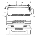
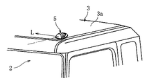
図1は、本発明に係る車両の正面図、図2は、図1のルーフ部の要部拡大図である。図1及び図2に示すように大型トラック1は、スタンダード(STD)ルーフ車両で車両の前部上側端位置例えば、キャブ2のルーフ部3の上面3aの左右両側部に灯火器5が設置されている。灯火器5は、ルーフ部3の上面3aに水平又は前方上向きに投光し、当該車両の被視認性、及び道路の上方に設置されている道路標識を数十メートル手前位置から照射して夜間の走行時に運転者が良好に視認し得るように設定されている。
【0011】
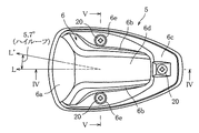
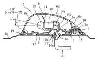
図3は灯火器5の平面図を示し、図4は図3の矢線IV―IVに沿う断面図、図5は図3の矢線V―Vに沿う断面図を示す。図3に示す平面図において灯火器5のケース6は、前部6aが前方に凸の大きな曲面をなし、両側部6bが前部6aから後部6cに向けて細くなり、後部6cが僅かに後方に凸の形状をなし、図4に示す側面視において、前部6aが大きな角度をなして上方に立ち上がり、上部6dが前部6aから大きな円弧の曲面をなして滑らかに傾斜して後部6cに至る形状をなし、両側部6bが前面視下方から上方に小さくなるように彎曲し、上面6dが大きな曲面をなす流線型をなしている。このケース6は、前部6aが透明、且つ広範囲に光を拡散させる魚眼ステップのレンズとされており、前部6a以外の部位が不透明とされている。また、図3に示すように両側部6bの略中央、及び後部6cの中央にねじ孔6eが設けられている。ケース6の下端にはフレーム7が装着固定されている。これらのケース6及びフレーム7は、樹脂部材例えば、プラスチック部材により形成されている。
【0012】
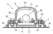
図4及び図5に示すように底板9にはリフレクタ11、ソケット12が固定され、ソケット12に光源としての白色の電球13が取り付けられている。ソケット12は、底板9に対して水平に配置されており、リフレクタ11は、電球13から発光された光を反射して光度を上げると共に、光軸方向を制御して後述するように所定方向に照射するようになっている。ハーネス14の線14a、14bは、グロメット16の孔16a、16b、及び底板9の孔9aを挿通してソケット12に接続される。底板9は、フレーム7に下方から着脱可能とされて当該フレーム7に固定され、リフレクタ11、ソケット12及び電球13がケース6内に収納される。
【0013】
グロメット16には曇り止め用の呼吸孔(図示せず)が穿設されており、ルーフハーネス貫通孔3bを呼吸孔としてケース6の内部とキャブ2の室内とを連通させてキャブ室内で呼吸するようにしてケース6の内部が曇ることを防止するようになっている。尚、前記呼吸孔は、挿通孔16a、16bと別個に設けることなく線14a、14bの挿通孔及び呼吸孔を1つの大きな孔として共用してもよい。このようにして灯火器5が構成されている。
【0014】
キャブ2のルーフ部3の上面3a側部には灯火器5を固定するためのブラケット17が溶着固定されており、ケース6の各ねじ孔6eに対応する位置に穿設されたボルト挿通孔の部位の下面にナット18が溶着されている。また、ルーフ部3の上面3aには、底板9の孔9aと対応する位置にハーネス14の線14a、14bを通すための貫通孔3bが穿設されている。
【0015】
図4及び図5に示すように灯火器5は、グロメット16がルーフ部3の孔3bに液密に装着され、ルーフ部上面3aにパッキン19を介して前部6aを前方に向けて液密に設置されてボルト20によりブラケット17に固定され、ハーネス14が不図示の電源に接続される。灯火器5は、ルーフ部3に取り付けた状態において光軸Lが、図3に示すように前方(正面)を向き、図4に示すように前方斜め上方を向くように調整される。この灯火器5は、車幅灯又はヘッドランプの少なくとも何れか一方を点灯したときに連動して点灯される。これにより、夜間走行時における灯火器5の点灯忘れを防止することができる。
【0016】
次に、灯火器5の光軸方向の調整について説明する。
図6に示すようにスタンダードルーフ車両1のルーフ部3の上面3aは、地上高2.8mとされており、当該高さ位置に灯火器5が設置される。道路30の上方に設置されている道路標識40は、路面30aから下端までの高さHaが5.15m、標識の高さHbが6.6mとされている。そこで、運転席から見て所定距離S例えば、前方40mの位置において道路標識40を視認可能な配光とするために灯火器5のリフレクタ11を調整して、電球13から発光される光の光軸Lを前方且つ水平面から前方上向きに5.4°に設定する。
【0017】
また、電球13の光度は、1灯当たりの法定規定最大光度60cdに対してバラツキ分を考慮して50cdとし、法規規定の最大光度上限に光度を設定する。
灯火器5は、リフレクタ11を有することで電球13からの光度、光量をアップさせることができると共に光軸角度を制御(調整)することができ、且つケース6の前部6aが広範囲に光を拡散させる魚眼ステップレンズとされていることで光軸中心から周辺に向けて光が拡散されて照射面の照度差が小さくなり、道路標識40の全体を照明して認知可能な光度、光量とすることができる。これにより、夜間走行時に運転者が道路標識40の40m手前の位置から当該道路標識40を認識することが可能となる。尚、図6において領域Iは、ヘッドランプによる照明範囲を示し、当該ヘッドランプでは道路標識40を照明することができない。
【0018】
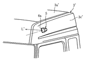
図7は、ハイ(Hi)ルーフ車両に灯火器5を設置した場合を示し、ハイルーフ部3’の左右の側面3c’(左側のみ図示)前部上端位置にケース6の前部6aを前方に向けて水平に設置したものである。ハイルーフ車両においては、灯火器5は、横置きとなり、光軸L’が図3に示すように前方を向き、図4に示すように車両側方に向くことになる。従って、灯火器5の光軸L’を前方斜め上向きに水平に対して5.3°に設定し、側方に2.8°に設定する。
【0019】
図6においてスタンダードルーフ部3の上面3aの前方への傾斜角を6.9°、ハイルーフ部3’ の側面3c’の前方への傾斜角を0°、キャブ2の傾斜角を水平に対して前方下向きに0.4°、灯火器5の取付位置をスタンダードルーフ部3の場合に地上高2.8m、ハイルーフ部3’の場合に2.88mとした場合、灯火器5をスタンダードルーフ部3の上面3aに灯火器5を設置した場合の光軸Lの仰角は12.7°(=6.9°+0.4°+5.4°)となり、ハイルーフ部3’の側面3c’に設置した場合の光軸L’の仰角は5.7°(=0.4°+5.3°)となる。
【0020】
従って、灯火器5の灯光を照射する光軸の角度を、前方上向きに0°〜15°好ましくは、水平面から5°〜6°の範囲に調整することにより夜間走行時に運転者がヘッドランプにより照明されない道路上方に設置されている道路標識40を40m手前から認識することが可能となる。
【0021】
【発明の効果】
本発明によれば、請求項1の発明では、車両のルーフ部に水平又は斜め前方上向きに投光して道路標識を照射する灯火器を配置することで、速度表示灯の廃止による夜間の被視認性及び夜間の道路標識に対する視認性が確保され、夜間走行時に運転者が道路標識を認識することができる。また、車両の外観の見栄えが向上する。
【0022】
請求項2の発明では、灯火器を車体のルーフ部の両側部に配設することで、ハイルーフ車両における夜間の被視認性及び夜間走行時における運転者の道路標識に対する視認性を確保することができる。
請求項3の発明では、灯火器は、前記車両の車幅灯又はヘッドランプの少なくとも何れか一方が点灯したとき連動して点灯することで、夜間の点灯忘れを確実に防止することができる。
【0023】
請求項4の発明では、灯火器は、灯光の照射角度を前方上向きに0〜15°傾けることで、道路の上方に設置されている道路標識を当該道路標識の手前で照明して認識可能としている。
請求項5の発明では、灯火器は、広範囲に光を拡散するためレンズを魚眼ステップとし、配光性向上用リフレクタを配設することで、前記リフレクタにより光度、光量をアップさせると共に光軸角度を制御し、前記魚眼ステップレンズにより光軸中心なら周辺に向けて光が拡散され照射面の照度差が小さくなるようにし、道路標識の全体を照明して認知可能とし、夜間走行時にヘッドランプでは照明されない道路上方に設置されている道路標識を認識することが可能となる。
【図面の簡単な説明】
【図1】本発明に係る車両の正面図である。
【図2】図1に示す車両のルーフ部の要部拡大斜視図である。
【図3】図2に示す灯火器の平面図である。
【図4】図3に示す灯火器の矢線IV―IVに沿う断面図である。
【図5】図3に示す灯火器の矢線V―Vに沿う断面図である。
【図6】図2に示す灯火器の光軸調整の説明図である。
【図7】図3に示す灯火器をハイルーフ車両に設置した場合の要部斜視図である。
【符号の説明】
1 車両
2 キャブ
3、3’ ルーフ部
5 灯火器
6 ケース
6a 前部(魚眼ステップレンズ)
7 フレーム
9 底板
11 リフレクタ
13 電球
19 パッキン
L、L’ 光軸
40 道路標識[0001]
TECHNICAL FIELD OF THE INVENTION
The present invention relates to a vehicle provided with a lighting device on a roof.
[0002]
[Prior art]
Conventionally, the installation of a speed display device has been compulsory for heavy trucks. This speed display device has three yellow-green speed indicator lights arranged side by side in a row on the upper surface of the roof portion of the vehicle, automatically lights up according to the vehicle speed, and can be visually recognized from 100 m ahead. One light (left) when the speed is 40 km / h or less, two lights (right and left) when the speed exceeds 40 km / h and 60 km / h or less, and three lights (left and right and center) when the speed exceeds 60 km / h. I was
[0003]
Since this speed indicator is installed on the upper surface of the roof of the vehicle, in addition to its original purpose of visibility, a road sign installed above the road and not illuminated by headlamps can be seen from several tens of meters ahead. It could be illuminated, which was effective for the driver checking the road sign (including the road information board) during night driving.
In addition, in a vehicle width lamp having a parabolic mirror that is provided above a front portion of a large vehicle at an interval in a vehicle width direction and reflects light from a light source, the parabolic mirror is vertically moved by two. There is a vehicle width light of a large vehicle in which a reflected main optical axis of a divided parabolic mirror is obliquely crossed in a vertical direction (for example, see Patent Document 1).
[0004]
[Patent Document 1]
Patent No. 3000797 [0005]
[Problems to be solved by the invention]
By the way, in recent years, due to the abolition of the speed indicator light, which has been required for the above-mentioned heavy trucks, there are cases where the visibility of road signs at the time of night driving is reduced and the visibility of road signs during night driving is reduced, so that the driver cannot confirm. is there.
The vehicle width light described in Patent Document 1 is simply for recognizing the width of a vehicle, and illuminates a road sign installed above a road like a speed indicator light. Can not.
[0006]
The present invention has been made in view of the above points, and an object of the present invention is to provide a vehicle that ensures visibility at night and recognition of a road sign.
[0007]
[Means for Solving the Problems]
In order to achieve the above object, in the invention of claim 1, a lighting device that projects light horizontally or diagonally forward and illuminates a road sign on a roof portion of a vehicle is disposed, so that visibility at night and traveling at night can be achieved. A driver's visibility to a road sign installed above a road that is not illuminated by a headlamp is ensured.
[0008]
According to the second aspect of the present invention, the lamps are disposed on both sides of the roof of the vehicle body, so that even in a high-roof vehicle, the visibility at night and the visibility of the driver to the road sign during night driving are ensured. .
According to the third aspect of the present invention, the lighting device is illuminated in conjunction with at least one of the vehicle width light and the headlamp when the vehicle is illuminated, thereby reliably preventing forgetting to light at night.
[0009]
According to the fourth aspect of the present invention, the lighting device illuminates a road sign installed above the road so as to be recognizable by inclining the irradiation angle of the light projection upward by 0 to 15 °.
According to the fifth aspect of the present invention, the lighting device diffuses light in a wide range, so that the lens is a fish-eye step, and the lighting device is provided with a reflector for improving light distribution, and the luminous intensity and the light amount are controlled by the reflector. And the optical axis angle is controlled, the fisheye step lens diffuses light from the center of the optical axis toward the periphery to reduce the illuminance difference on the irradiated surface, and illuminates and recognizes the entire road sign This allows the driver to recognize from a position in front of a road sign during night driving.
[0010]
BEST MODE FOR CARRYING OUT THE INVENTION
Hereinafter, preferred embodiments of the present invention will be illustratively described in detail with reference to the drawings.
FIG. 1 is a front view of a vehicle according to the present invention, and FIG. 2 is an enlarged view of a main part of a roof portion of FIG. As shown in FIGS. 1 and 2, the heavy-duty truck 1 is a standard (STD) roof vehicle, and a lighting device 5 is installed at an upper front end position of the vehicle, for example, on both left and right sides of an upper surface 3 a of a roof portion 3 of a cab 2. ing. The lighting device 5 emits light horizontally or forward upward on the upper surface 3a of the roof portion 3, and illuminates the visibility of the vehicle and a road sign installed above the road from a position several tens of meters ahead at night. It is set so that the driver can visually recognize the vehicle when traveling.
[0011]
FIG. 3 is a plan view of the lighting device 5, FIG. 4 is a sectional view taken along the line IV-IV of FIG. 3, and FIG. 5 is a sectional view taken along the line VV of FIG. In the plan view shown in FIG. 3, the case 6 of the lighting device 5 has a front portion 6 a that forms a large curved surface that is convex forward, both side portions 6 b become thinner from the front portion 6 a to the rear portion 6 c, and the rear portion 6 c is slightly rearward. In the side view shown in FIG. 4, the front portion 6a rises upward at a large angle, and the upper portion 6d forms a large arc-shaped curved surface from the front portion 6a and smoothly slopes toward the rear portion 6c. It has a streamlined shape in which the side portions 6b are curved so as to become smaller upward from below in front view, and the upper surface 6d forms a large curved surface. In this case 6, the front part 6a is a transparent and fish-eye step lens that diffuses light over a wide range, and the part other than the front part 6a is opaque. As shown in FIG. 3, a screw hole 6e is provided at substantially the center of both sides 6b and the center of the rear part 6c. A frame 7 is attached and fixed to the lower end of the case 6. The case 6 and the frame 7 are formed of a resin member, for example, a plastic member.
[0012]
As shown in FIGS. 4 and 5, a reflector 11 and a socket 12 are fixed to the bottom plate 9, and a white light bulb 13 as a light source is attached to the socket 12. The socket 12 is disposed horizontally with respect to the bottom plate 9, and the reflector 11 reflects light emitted from the light bulb 13 to increase the luminous intensity, and controls the optical axis direction to move in a predetermined direction as described later. Irradiation. The wires 14 a and 14 b of the harness 14 are connected to the socket 12 through the holes 16 a and 16 b of the grommet 16 and the holes 9 a of the bottom plate 9. The bottom plate 9 is detachable from the frame 7 from below and is fixed to the frame 7, and the reflector 11, the socket 12, and the light bulb 13 are stored in the case 6.
[0013]
The grommet 16 is provided with a breathing hole (not shown) for preventing fogging. The interior of the case 6 communicates with the room of the cab 2 using the roof harness through hole 3b as a breathing hole to breathe in the cab room. Thus, the inside of the case 6 is prevented from fogging. Note that the breathing hole may be used as one large hole, without providing the breathing hole separately from the insertion holes 16a and 16b. The lighting device 5 is configured in this manner.
[0014]
A bracket 17 for fixing the lighting device 5 is welded and fixed to the upper surface 3a side of the roof portion 3 of the cab 2, and a bolt insertion hole formed at a position corresponding to each screw hole 6e of the case 6 is provided. A nut 18 is welded to the lower surface of the part. In the upper surface 3a of the roof portion 3, a through hole 3b for passing the wires 14a, 14b of the harness 14 is formed at a position corresponding to the hole 9a of the bottom plate 9.
[0015]
As shown in FIGS. 4 and 5, in the lighting device 5, the grommet 16 is mounted in the hole 3 b of the roof portion 3 in a liquid-tight manner, and the front portion 6 a is directed forward with the packing 19 on the roof portion upper surface 3 a via the packing 19. The harness 14 is connected to a power supply (not shown). The lamp 5 is adjusted so that the optical axis L faces forward (front) as shown in FIG. 3 and diagonally forward and upward as shown in FIG. The lighting device 5 is turned on in conjunction with turning on at least one of the vehicle width light and the headlamp. As a result, it is possible to prevent the lighting device 5 from being forgotten to be turned on during night driving.
[0016]
Next, the adjustment of the lighting device 5 in the optical axis direction will be described.
As shown in FIG. 6, the upper surface 3a of the roof portion 3 of the standard roof vehicle 1 has a ground height of 2.8 m, and the lighting device 5 is installed at the height. The road sign 40 installed above the road 30 has a height Ha from the road surface 30a to the lower end of 5.15 m and a height Hb of the sign of 6.6 m. Therefore, the reflector 11 of the lighting device 5 is adjusted to provide a light distribution in which the road sign 40 can be visually recognized at a predetermined distance S from the driver's seat, for example, at a position 40 m ahead, and the light emitted from the light bulb 13 is adjusted. The axis L is set at 5.4 ° forward and upward from the horizontal plane.
[0017]
The luminous intensity of the light bulb 13 is set to 50 cd in consideration of the variation with respect to the legally stipulated maximum luminous intensity 60 cd per lamp, and the luminous intensity is set to the legally stipulated maximum luminous intensity upper limit.
Since the lighting device 5 has the reflector 11, the luminous intensity and the light amount from the light bulb 13 can be increased, the optical axis angle can be controlled (adjusted), and the front portion 6 a of the case 6 can transmit light over a wide range. The light is diffused from the center of the optical axis toward the periphery due to being a fish-eye step lens for diffusion, and the illuminance difference on the irradiation surface is reduced. can do. This allows the driver to recognize the road sign 40 from a position 40 m before the road sign 40 during night driving. In FIG. 6, a region I indicates an illumination range of a headlamp, and the headlamp cannot illuminate the road sign 40.
[0018]
FIG. 7 shows a case in which the lighting device 5 is installed in a high (Hi) roof vehicle. The front portion 6a of the case 6 is located forward at the upper end position of the left and right side surfaces 3c '(only the left side is shown) of the high roof portion 3'. It was installed horizontally facing. In a high-roof vehicle, the lighting device 5 is placed horizontally, and the optical axis L 'faces forward as shown in FIG. 3 and sideways as shown in FIG. Therefore, the optical axis L ′ of the lighting device 5 is set to 5.3 ° with respect to the horizontal diagonally forward and upward, and 2.8 ° to the side.
[0019]
In FIG. 6, the forward inclination angle of the upper surface 3a of the standard roof portion 3 is 6.9 °, the forward inclination angle of the side surface 3c ′ of the high roof portion 3 ′ is 0 °, and the inclination angle of the cab 2 is horizontal. When the mounting position of the lighting device 5 is set at 2.8 m above the ground in the case of the standard roof portion 3 and 2.88 m in the case of the high roof portion 3 ′, the lighting device 5 is mounted on the standard roof portion 3. The elevation angle of the optical axis L when the lighting device 5 is installed on the upper surface 3a is 12.7 ° (= 6.9 ° + 0.4 ° + 5.4 °), and is installed on the side surface 3c ′ of the high roof portion 3 ′. In this case, the elevation angle of the optical axis L ′ is 5.7 ° (= 0.4 ° + 5.3 °).
[0020]
Therefore, by adjusting the angle of the optical axis for irradiating the lamp light of the lighting device 5 forwardly upward from 0 ° to 15 °, preferably from 5 ° to 6 ° from the horizontal plane, the driver can use the headlamp during night driving. It is possible to recognize the road sign 40 installed above the unilluminated road from a position 40 m short of the road.
[0021]
【The invention's effect】
According to the present invention, according to the first aspect of the present invention, by arranging a lighting device that irradiates a road sign by projecting horizontally or diagonally forward and upward on the roof portion of the vehicle, the speed display lamp is eliminated and nighttime exposure is reduced. Visibility and visibility to road signs at night are ensured, and the driver can recognize the road signs at night. In addition, the appearance of the vehicle is improved.
[0022]
According to the second aspect of the present invention, by arranging the lighting devices on both sides of the roof of the vehicle body, it is possible to ensure the visibility of the high-roof vehicle at night and the visibility of the driver to the road sign during night driving. it can.
According to the third aspect of the present invention, the lamp is lit in conjunction with at least one of the vehicle side light and the headlamp when the vehicle is lit, so that forgetting to light at night can be reliably prevented.
[0023]
According to the fourth aspect of the present invention, the lighting device can recognize the road sign installed above the road by illuminating the road sign in front of the road sign by inclining the irradiation angle of the lamp light upward by 0 to 15 °. I have.
According to the fifth aspect of the present invention, the lamp has a fisheye step as a lens for diffusing light in a wide range, and a reflector for improving light distribution is provided, so that the luminous intensity and light amount are increased by the reflector and the optical axis is increased. The angle is controlled, so that the fisheye step lens diffuses light toward the periphery if the center of the optical axis and reduces the illuminance difference on the illuminated surface, illuminates and recognizes the entire road sign, and allows the head to travel at night. It is possible to recognize a road sign installed above a road that is not illuminated by a lamp.
[Brief description of the drawings]
FIG. 1 is a front view of a vehicle according to the present invention.
FIG. 2 is an enlarged perspective view of a main part of a roof portion of the vehicle shown in FIG.
FIG. 3 is a plan view of the lighting device shown in FIG. 2;
FIG. 4 is a sectional view of the lighting device shown in FIG. 3, taken along the line IV-IV.
5 is a sectional view of the lighting device shown in FIG. 3, taken along the line VV.
6 is an explanatory diagram of the optical axis adjustment of the lighting device shown in FIG. 2;
FIG. 7 is a perspective view of a main part when the lighting device shown in FIG. 3 is installed in a high-roof vehicle.
[Explanation of symbols]
DESCRIPTION OF SYMBOLS 1 Vehicle 2 Cab 3 and 3 'Roof part 5 Lighting device 6 Case 6a Front part (fisheye step lens)
7 Frame 9 Bottom plate 11 Reflector 13 Light bulb 19 Packing L, L 'Optical axis 40 Road sign