JP2004261580A - System for detection of cardiac event - Google Patents
System for detection of cardiac event Download PDFInfo
- Publication number
- JP2004261580A JP2004261580A JP2003323973A JP2003323973A JP2004261580A JP 2004261580 A JP2004261580 A JP 2004261580A JP 2003323973 A JP2003323973 A JP 2003323973A JP 2003323973 A JP2003323973 A JP 2003323973A JP 2004261580 A JP2004261580 A JP 2004261580A
- Authority
- JP
- Japan
- Prior art keywords
- electrogram
- segment
- cardiac
- heart
- patient
- Prior art date
- Legal status (The legal status is an assumption and is not a legal conclusion. Google has not performed a legal analysis and makes no representation as to the accuracy of the status listed.)
- Pending
Links
- 230000000747 cardiac effect Effects 0.000 title claims abstract description 250
- 238000001514 detection method Methods 0.000 title claims abstract description 85
- 206010000891 acute myocardial infarction Diseases 0.000 claims abstract description 71
- 230000015654 memory Effects 0.000 claims description 83
- 208000028867 ischemia Diseases 0.000 claims description 53
- 238000000034 method Methods 0.000 claims description 49
- 230000001788 irregular Effects 0.000 claims description 28
- 238000012545 processing Methods 0.000 claims description 28
- 230000006870 function Effects 0.000 claims description 22
- 208000010125 myocardial infarction Diseases 0.000 claims description 17
- 238000004891 communication Methods 0.000 claims description 16
- 230000000630 rising effect Effects 0.000 claims description 16
- 230000008569 process Effects 0.000 claims description 14
- 238000007920 subcutaneous administration Methods 0.000 claims description 14
- 206010003119 arrhythmia Diseases 0.000 claims description 10
- 230000006793 arrhythmia Effects 0.000 claims description 9
- 230000036471 bradycardia Effects 0.000 claims description 8
- 208000001871 Tachycardia Diseases 0.000 claims description 7
- 230000005540 biological transmission Effects 0.000 claims description 7
- 208000006218 bradycardia Diseases 0.000 claims description 6
- 230000006794 tachycardia Effects 0.000 claims description 6
- 230000001174 ascending effect Effects 0.000 claims description 5
- 230000002861 ventricular Effects 0.000 claims description 5
- 206010003658 Atrial Fibrillation Diseases 0.000 claims description 4
- 208000000418 Premature Cardiac Complexes Diseases 0.000 claims description 4
- 210000005241 right ventricle Anatomy 0.000 claims description 4
- 230000000638 stimulation Effects 0.000 claims description 4
- 230000001746 atrial effect Effects 0.000 claims description 3
- 210000005245 right atrium Anatomy 0.000 claims description 3
- 210000002620 vena cava superior Anatomy 0.000 claims description 3
- 230000003213 activating effect Effects 0.000 claims description 2
- 230000001419 dependent effect Effects 0.000 claims 2
- 230000004044 response Effects 0.000 claims 2
- 208000000059 Dyspnea Diseases 0.000 claims 1
- 206010013975 Dyspnoeas Diseases 0.000 claims 1
- 230000002457 bidirectional effect Effects 0.000 claims 1
- 230000008859 change Effects 0.000 abstract description 17
- 238000000605 extraction Methods 0.000 description 16
- 238000012544 monitoring process Methods 0.000 description 16
- 230000003466 anti-cipated effect Effects 0.000 description 14
- 238000010586 diagram Methods 0.000 description 13
- 238000012795 verification Methods 0.000 description 12
- 238000002513 implantation Methods 0.000 description 9
- 230000000694 effects Effects 0.000 description 8
- 230000001755 vocal effect Effects 0.000 description 8
- 239000002184 metal Substances 0.000 description 6
- 229910052751 metal Inorganic materials 0.000 description 6
- 238000012360 testing method Methods 0.000 description 6
- 239000004020 conductor Substances 0.000 description 5
- 210000004165 myocardium Anatomy 0.000 description 5
- 230000007935 neutral effect Effects 0.000 description 5
- 238000003860 storage Methods 0.000 description 5
- 208000003663 ventricular fibrillation Diseases 0.000 description 5
- 230000002159 abnormal effect Effects 0.000 description 4
- 238000004458 analytical method Methods 0.000 description 4
- 230000008901 benefit Effects 0.000 description 4
- 230000006378 damage Effects 0.000 description 4
- 230000007423 decrease Effects 0.000 description 4
- 239000007943 implant Substances 0.000 description 4
- 230000000302 ischemic effect Effects 0.000 description 4
- 230000033001 locomotion Effects 0.000 description 4
- 208000031225 myocardial ischemia Diseases 0.000 description 4
- 206010003662 Atrial flutter Diseases 0.000 description 3
- 201000000057 Coronary Stenosis Diseases 0.000 description 3
- 206010047289 Ventricular extrasystoles Diseases 0.000 description 3
- 230000009471 action Effects 0.000 description 3
- 239000008280 blood Substances 0.000 description 3
- 210000004369 blood Anatomy 0.000 description 3
- 206010061592 cardiac fibrillation Diseases 0.000 description 3
- 229940079593 drug Drugs 0.000 description 3
- 239000003814 drug Substances 0.000 description 3
- 230000002600 fibrillogenic effect Effects 0.000 description 3
- 230000035945 sensitivity Effects 0.000 description 3
- 229960000103 thrombolytic agent Drugs 0.000 description 3
- 230000001960 triggered effect Effects 0.000 description 3
- 238000012935 Averaging Methods 0.000 description 2
- 206010015856 Extrasystoles Diseases 0.000 description 2
- 208000031481 Pathologic Constriction Diseases 0.000 description 2
- 206010042602 Supraventricular extrasystoles Diseases 0.000 description 2
- 208000007536 Thrombosis Diseases 0.000 description 2
- 102000003978 Tissue Plasminogen Activator Human genes 0.000 description 2
- 108090000373 Tissue Plasminogen Activator Proteins 0.000 description 2
- 238000002399 angioplasty Methods 0.000 description 2
- 238000004364 calculation method Methods 0.000 description 2
- 210000004351 coronary vessel Anatomy 0.000 description 2
- 238000003745 diagnosis Methods 0.000 description 2
- 239000003527 fibrinolytic agent Substances 0.000 description 2
- 230000000977 initiatory effect Effects 0.000 description 2
- WABPQHHGFIMREM-UHFFFAOYSA-N lead(0) Chemical compound [Pb] WABPQHHGFIMREM-UHFFFAOYSA-N 0.000 description 2
- 230000028161 membrane depolarization Effects 0.000 description 2
- 230000002250 progressing effect Effects 0.000 description 2
- 230000010349 pulsation Effects 0.000 description 2
- 230000009467 reduction Effects 0.000 description 2
- 230000002336 repolarization Effects 0.000 description 2
- 230000005236 sound signal Effects 0.000 description 2
- 230000036262 stenosis Effects 0.000 description 2
- 208000037804 stenosis Diseases 0.000 description 2
- 229960000187 tissue plasminogen activator Drugs 0.000 description 2
- 210000005166 vasculature Anatomy 0.000 description 2
- 206010002383 Angina Pectoris Diseases 0.000 description 1
- 206010060965 Arterial stenosis Diseases 0.000 description 1
- BSYNRYMUTXBXSQ-UHFFFAOYSA-N Aspirin Chemical compound CC(=O)OC1=CC=CC=C1C(O)=O BSYNRYMUTXBXSQ-UHFFFAOYSA-N 0.000 description 1
- 201000001320 Atherosclerosis Diseases 0.000 description 1
- 208000002102 Atrial Premature Complexes Diseases 0.000 description 1
- 206010008479 Chest Pain Diseases 0.000 description 1
- 206010008469 Chest discomfort Diseases 0.000 description 1
- 206010011086 Coronary artery occlusion Diseases 0.000 description 1
- 206010011089 Coronary artery stenosis Diseases 0.000 description 1
- SNIOPGDIGTZGOP-UHFFFAOYSA-N Nitroglycerin Chemical compound [O-][N+](=O)OCC(O[N+]([O-])=O)CO[N+]([O-])=O SNIOPGDIGTZGOP-UHFFFAOYSA-N 0.000 description 1
- 239000000006 Nitroglycerin Substances 0.000 description 1
- 208000002193 Pain Diseases 0.000 description 1
- 206010033557 Palpitations Diseases 0.000 description 1
- 206010057469 Vascular stenosis Diseases 0.000 description 1
- 208000027418 Wounds and injury Diseases 0.000 description 1
- 229960001138 acetylsalicylic acid Drugs 0.000 description 1
- 230000004913 activation Effects 0.000 description 1
- 230000006978 adaptation Effects 0.000 description 1
- 238000002583 angiography Methods 0.000 description 1
- 239000003146 anticoagulant agent Substances 0.000 description 1
- 229940127218 antiplatelet drug Drugs 0.000 description 1
- 210000001367 artery Anatomy 0.000 description 1
- QVGXLLKOCUKJST-UHFFFAOYSA-N atomic oxygen Chemical compound [O] QVGXLLKOCUKJST-UHFFFAOYSA-N 0.000 description 1
- 230000017531 blood circulation Effects 0.000 description 1
- 230000023555 blood coagulation Effects 0.000 description 1
- 230000036770 blood supply Effects 0.000 description 1
- 230000003139 buffering effect Effects 0.000 description 1
- 239000006227 byproduct Substances 0.000 description 1
- 238000006243 chemical reaction Methods 0.000 description 1
- 230000000052 comparative effect Effects 0.000 description 1
- 238000012790 confirmation Methods 0.000 description 1
- 230000008602 contraction Effects 0.000 description 1
- 208000029078 coronary artery disease Diseases 0.000 description 1
- 238000013075 data extraction Methods 0.000 description 1
- 230000034994 death Effects 0.000 description 1
- 230000000994 depressogenic effect Effects 0.000 description 1
- 238000013461 design Methods 0.000 description 1
- 239000000890 drug combination Substances 0.000 description 1
- 238000002565 electrocardiography Methods 0.000 description 1
- 238000001914 filtration Methods 0.000 description 1
- 229960003711 glyceryl trinitrate Drugs 0.000 description 1
- 208000019622 heart disease Diseases 0.000 description 1
- 230000001976 improved effect Effects 0.000 description 1
- 208000014674 injury Diseases 0.000 description 1
- 230000003993 interaction Effects 0.000 description 1
- 238000011835 investigation Methods 0.000 description 1
- 210000005246 left atrium Anatomy 0.000 description 1
- 238000004519 manufacturing process Methods 0.000 description 1
- 238000005259 measurement Methods 0.000 description 1
- 230000007246 mechanism Effects 0.000 description 1
- 238000002483 medication Methods 0.000 description 1
- 238000012986 modification Methods 0.000 description 1
- 230000004048 modification Effects 0.000 description 1
- 238000012806 monitoring device Methods 0.000 description 1
- 230000002107 myocardial effect Effects 0.000 description 1
- 239000007922 nasal spray Substances 0.000 description 1
- 229910052760 oxygen Inorganic materials 0.000 description 1
- 239000001301 oxygen Substances 0.000 description 1
- 238000004806 packaging method and process Methods 0.000 description 1
- 230000010412 perfusion Effects 0.000 description 1
- 230000000737 periodic effect Effects 0.000 description 1
- 230000002093 peripheral effect Effects 0.000 description 1
- 230000002688 persistence Effects 0.000 description 1
- 230000037081 physical activity Effects 0.000 description 1
- 230000002028 premature Effects 0.000 description 1
- 238000003825 pressing Methods 0.000 description 1
- 238000004393 prognosis Methods 0.000 description 1
- 238000011084 recovery Methods 0.000 description 1
- 238000012552 review Methods 0.000 description 1
- 230000033764 rhythmic process Effects 0.000 description 1
- 238000005070 sampling Methods 0.000 description 1
- 230000035939 shock Effects 0.000 description 1
- 230000011664 signaling Effects 0.000 description 1
- 230000001360 synchronised effect Effects 0.000 description 1
- 239000003826 tablet Substances 0.000 description 1
- 238000002560 therapeutic procedure Methods 0.000 description 1
- 230000002537 thrombolytic effect Effects 0.000 description 1
- 230000001052 transient effect Effects 0.000 description 1
Images


Classifications
-
- A—HUMAN NECESSITIES
- A61—MEDICAL OR VETERINARY SCIENCE; HYGIENE
- A61B—DIAGNOSIS; SURGERY; IDENTIFICATION
- A61B5/00—Measuring for diagnostic purposes; Identification of persons
- A61B5/02—Detecting, measuring or recording pulse, heart rate, blood pressure or blood flow; Combined pulse/heart-rate/blood pressure determination; Evaluating a cardiovascular condition not otherwise provided for, e.g. using combinations of techniques provided for in this group with electrocardiography or electroauscultation; Heart catheters for measuring blood pressure
- A61B5/024—Detecting, measuring or recording pulse rate or heart rate
- A61B5/0245—Detecting, measuring or recording pulse rate or heart rate by using sensing means generating electric signals, i.e. ECG signals
- A61B5/02455—Detecting, measuring or recording pulse rate or heart rate by using sensing means generating electric signals, i.e. ECG signals provided with high/low alarm devices
-
- A—HUMAN NECESSITIES
- A61—MEDICAL OR VETERINARY SCIENCE; HYGIENE
- A61B—DIAGNOSIS; SURGERY; IDENTIFICATION
- A61B5/00—Measuring for diagnostic purposes; Identification of persons
- A61B5/0002—Remote monitoring of patients using telemetry, e.g. transmission of vital signals via a communication network
- A61B5/0031—Implanted circuitry
-
- A—HUMAN NECESSITIES
- A61—MEDICAL OR VETERINARY SCIENCE; HYGIENE
- A61B—DIAGNOSIS; SURGERY; IDENTIFICATION
- A61B5/00—Measuring for diagnostic purposes; Identification of persons
- A61B5/24—Detecting, measuring or recording bioelectric or biomagnetic signals of the body or parts thereof
- A61B5/25—Bioelectric electrodes therefor
- A61B5/279—Bioelectric electrodes therefor specially adapted for particular uses
- A61B5/28—Bioelectric electrodes therefor specially adapted for particular uses for electrocardiography [ECG]
- A61B5/283—Invasive
- A61B5/287—Holders for multiple electrodes, e.g. electrode catheters for electrophysiological study [EPS]
-
- A—HUMAN NECESSITIES
- A61—MEDICAL OR VETERINARY SCIENCE; HYGIENE
- A61B—DIAGNOSIS; SURGERY; IDENTIFICATION
- A61B5/00—Measuring for diagnostic purposes; Identification of persons
- A61B5/24—Detecting, measuring or recording bioelectric or biomagnetic signals of the body or parts thereof
- A61B5/316—Modalities, i.e. specific diagnostic methods
- A61B5/318—Heart-related electrical modalities, e.g. electrocardiography [ECG]
- A61B5/346—Analysis of electrocardiograms
- A61B5/349—Detecting specific parameters of the electrocardiograph cycle
- A61B5/352—Detecting R peaks, e.g. for synchronising diagnostic apparatus; Estimating R-R interval
-
- A—HUMAN NECESSITIES
- A61—MEDICAL OR VETERINARY SCIENCE; HYGIENE
- A61B—DIAGNOSIS; SURGERY; IDENTIFICATION
- A61B5/00—Measuring for diagnostic purposes; Identification of persons
- A61B5/24—Detecting, measuring or recording bioelectric or biomagnetic signals of the body or parts thereof
- A61B5/316—Modalities, i.e. specific diagnostic methods
- A61B5/318—Heart-related electrical modalities, e.g. electrocardiography [ECG]
- A61B5/346—Analysis of electrocardiograms
- A61B5/349—Detecting specific parameters of the electrocardiograph cycle
- A61B5/364—Detecting abnormal ECG interval, e.g. extrasystoles, ectopic heartbeats
-
- A—HUMAN NECESSITIES
- A61—MEDICAL OR VETERINARY SCIENCE; HYGIENE
- A61B—DIAGNOSIS; SURGERY; IDENTIFICATION
- A61B5/00—Measuring for diagnostic purposes; Identification of persons
- A61B5/24—Detecting, measuring or recording bioelectric or biomagnetic signals of the body or parts thereof
- A61B5/316—Modalities, i.e. specific diagnostic methods
- A61B5/318—Heart-related electrical modalities, e.g. electrocardiography [ECG]
- A61B5/346—Analysis of electrocardiograms
- A61B5/349—Detecting specific parameters of the electrocardiograph cycle
- A61B5/366—Detecting abnormal QRS complex, e.g. widening
-
- A—HUMAN NECESSITIES
- A61—MEDICAL OR VETERINARY SCIENCE; HYGIENE
- A61B—DIAGNOSIS; SURGERY; IDENTIFICATION
- A61B2560/00—Constructional details of operational features of apparatus; Accessories for medical measuring apparatus
- A61B2560/02—Operational features
- A61B2560/0204—Operational features of power management
- A61B2560/0209—Operational features of power management adapted for power saving
-
- A—HUMAN NECESSITIES
- A61—MEDICAL OR VETERINARY SCIENCE; HYGIENE
- A61B—DIAGNOSIS; SURGERY; IDENTIFICATION
- A61B5/00—Measuring for diagnostic purposes; Identification of persons
- A61B5/74—Details of notification to user or communication with user or patient ; user input means
- A61B5/746—Alarms related to a physiological condition, e.g. details of setting alarm thresholds or avoiding false alarms
-
- A—HUMAN NECESSITIES
- A61—MEDICAL OR VETERINARY SCIENCE; HYGIENE
- A61B—DIAGNOSIS; SURGERY; IDENTIFICATION
- A61B5/00—Measuring for diagnostic purposes; Identification of persons
- A61B5/74—Details of notification to user or communication with user or patient ; user input means
- A61B5/7465—Arrangements for interactive communication between patient and care services, e.g. by using a telephone network
Landscapes
- Health & Medical Sciences (AREA)
- Life Sciences & Earth Sciences (AREA)
- Cardiology (AREA)
- Engineering & Computer Science (AREA)
- Molecular Biology (AREA)
- General Health & Medical Sciences (AREA)
- Pathology (AREA)
- Biomedical Technology (AREA)
- Heart & Thoracic Surgery (AREA)
- Medical Informatics (AREA)
- Physics & Mathematics (AREA)
- Surgery (AREA)
- Animal Behavior & Ethology (AREA)
- Biophysics (AREA)
- Public Health (AREA)
- Veterinary Medicine (AREA)
- Physiology (AREA)
- Computer Networks & Wireless Communication (AREA)
- Signal Processing (AREA)
- Measurement And Recording Of Electrical Phenomena And Electrical Characteristics Of The Living Body (AREA)
- Electrotherapy Devices (AREA)
- Measuring And Recording Apparatus For Diagnosis (AREA)
- Apparatus For Radiation Diagnosis (AREA)
Abstract
Description
本発明は、人間の患者に埋め込まれる装置を含み、心臓事象の始まりを自動的に検知することを目的とするシステムの分野にある。 The present invention is in the field of systems that include devices that are implanted in a human patient and that are intended to automatically detect the onset of a cardiac event.
心臓病は米国における死亡の主な原因である。心臓発作(急性心筋梗塞(AMI)としても知られる)は通常1つ又はそれ以上の冠状動脈を流れる血液を妨げる血栓が原因である。AMIは冠状動脈心臓病に共通の及び生死に関わる厄介な問題である。心筋の潅流が(例えば、組織プラスミノゲン活性化因子(tPA)といった血栓溶解薬剤の投与により)早く回復すればするほど、患者の心臓発作からの予後及び救済がよりよいものとなる。心筋への損害の程度は心筋への血流の回復前の時間の長さに大いに左右される。 Heart disease is the leading cause of death in the United States. A heart attack (also known as acute myocardial infarction (AMI)) is usually due to a thrombus that blocks blood flowing through one or more coronary arteries. AMI is a common and life-threatening complication of coronary heart disease. The faster the myocardial perfusion is restored (eg, by administration of a thrombolytic agent such as tissue plasminogen activator (tPA)), the better the prognosis and rescue of the patient from a heart attack. The extent of damage to the myocardium depends greatly on the length of time before restoration of blood flow to the myocardium.
心筋虚血は心筋における血液(酸素)の供給と需要の一時的な不均衡が原因である。それは通常、1つ又はそれ以上の冠状動脈がアテローム性動脈硬化により詰まったときに身体活動又は心拍数を増加させる他の原因により引き起こされる。患者はしばしば(しかし常にではない)心筋が虚血に直面しているとき、胸の不快感(狭心症)を経験する。 Myocardial ischemia is caused by a temporary imbalance in blood (oxygen) supply and demand in the myocardium. It is usually caused by physical activity or other causes that increase heart rate when one or more coronary arteries become blocked by atherosclerosis. Patients often (but not always) experience chest discomfort (angina) when the myocardium is facing ischemia.
急性心筋梗塞及び虚血は患者の心電図(ECG)から比較的短い(5分以下)時間周期にわたるSTセグメントシフト(すなわち、電圧変化)を記録することにより検知される。しかし、患者の正常なECGパターンを知らないで、標準の12の主要ECGからの検知は信頼できない。さらに、皮下に埋め込まれた装置に関連する、STセグメントシフトを検知する皮下電極の理想的な配置は、従来技術では考察されていない。 Acute myocardial infarction and ischemia are detected by recording ST segment shifts (ie, voltage changes) over a relatively short (less than 5 minutes) time period from the patient's electrocardiogram (ECG). However, without knowing the patient's normal ECG pattern, detection from the standard 12 major ECGs is unreliable. Furthermore, the ideal placement of a subcutaneous electrode for detecting ST segment shifts associated with a subcutaneously implanted device has not been considered in the prior art.
Fischell等は米国特許6,112,116及び6,272,379で急性心筋梗塞の始まりを検知する及び患者に処置及び警告の両方を提供する埋め込み可能なシステムを記載している。Fischell等は警報のきっかけとして心臓の電極からの患者の電気記録図のS-Tセグメントのシフトの検知を論じているが、さらに高度な検知アルゴリズムを提供し、偽陽性及び偽陰性検知の可能性を減少させることが望ましい。さらにこれらの特許はこうしたシステムをプログラミングするいくつかの望ましい側面を記載しているが、さらなるプログラム制御性及び警報制御特徴を提供することが望ましい。 Fischell et al. In U.S. Patents 6,112,116 and 6,272,379 describe implantable systems for detecting the onset of acute myocardial infarction and providing both treatment and alerting to a patient. Fischell et al. Discuss the detection of ST segment shifts in patient electrograms from cardiac electrodes as a trigger for alarms, but provide more sophisticated detection algorithms to reduce the possibility of false positive and false negative detection It is desirable to make it. Further, while these patents describe some desirable aspects of programming such systems, it is desirable to provide additional programmability and alarm control features.
抗頻脈のペースメーカー及び埋め込み型徐細動器(ICDs)は心臓の不整脈を検知できるが、どれもこれまでのところ不整脈と無関係な又は連動する虚血及び急性心筋梗塞を検知するように設計されていない。 Anti-tachycardia pacemakers and implantable defibrillators (ICDs) can detect cardiac arrhythmias, but none are designed to detect ischemia and acute myocardial infarction so far independent of or associated with arrhythmias. Not.
米国特許番号6,112,116及び6,272,379で、Fischell等は、記録された電気記録図及び/又は心電図データの保存について論じている。しかし、適切な電気記録図及び/又は心電図データ及び他の適切なデータをシステムメモリの限られた容量に最適に保存する技術については詳しく述べられていない。 In U.S. Patent Nos. 6,112,116 and 6,272,379, Fischell et al. Discuss the storage of recorded electrogram and / or electrocardiogram data. However, techniques for optimally storing appropriate electrogram and / or electrocardiogram data and other appropriate data in a limited amount of system memory are not described in detail.
M.Zehenderによる米国特許番号5,497,780では、「異常拍動を除去する目的」を有する装置について記述されている。これを行うために、Zehenderは心臓内に設置される厳密に2つの電極及び心臓の外側に設置される厳密に1つの電極を必要とする。複数の電極が使用されるが、心臓発作を検知する電気記録図を提供する最も実用的なセンサは心臓内又はその近くに設置される単一の電極を使用する。 U.S. Pat. No. 5,497,780 to M. Zehender describes a device having "the purpose of eliminating abnormal beats". To do this, Zehender requires exactly two electrodes located inside the heart and exactly one electrode located outside the heart. Although multiple electrodes are used, the most practical sensors that provide an electrogram to detect a heart attack use a single electrode placed in or near the heart.
Zehenderのアルゴリズムの図面はST SIGNAL ANALYSISと表示される単一の囲みから成り、その分析が何を含むかについての詳細がない。彼の検知アルゴリズムに関するただ一つの記述は、ECGと正常なECGカーブの参照信号との比較を使用することである。Zehenderはこうした比較が行われるアルゴリズムを教授するための詳細を論じていないばかりか、どのように「正常なECGカーブ」を識別するのかについての説明もしていない。それぞれの患者は異なる「正常な」基準ECGを有することが多く、それは心臓発作又は虚血を検知する任意のシステム又はアルゴリズムの根幹である。 The drawing of Zehender's algorithm consists of a single box labeled ST SIGNAL ANALYSIS, with no details on what the analysis involves. The only statement about his detection algorithm is to use a comparison of the ECG with a reference signal of a normal ECG curve. Zehender does not discuss the details of teaching the algorithm by which these comparisons are made, nor does it explain how to identify "normal ECG curves." Each patient often has a different "normal" reference ECG, which is the basis of any system or algorithm that detects a heart attack or ischemia.
さらに、ZehenderはST信号分析は3分ごとに実行されるべきであると提案している。3分より長い時間間隔及び短い時間間隔の両方を使用して、急性心筋梗塞の発生初期に又は発生からしばらくして見られるECGの一定の変化を捕捉することが望ましい。長い観察周期はまた、「基準」ECGのささいなゆっくりと展開する変化を明らかにするのに重要である。Zehenderは心拍数に基づく異なる正常な曲線を有する虚血の検知について何も述べていない。運動誘発性虚血と急性心筋梗塞を区別するために、STセグメントシフトと心拍数又はR-R間隔を関連づけることが重要である。 In addition, Zehender proposes that ST signal analysis should be performed every three minutes. It is desirable to use both time intervals longer than 3 minutes and shorter time intervals to capture certain changes in the ECG that occur early or shortly after the onset of acute myocardial infarction. Long observation cycles are also important in revealing small, slowly evolving changes in the "reference" ECG. Zehender does not state anything about detecting ischemia with different normal curves based on heart rate. It is important to correlate ST segment shift with heart rate or R-R interval to distinguish exercise-induced ischemia from acute myocardial infarction.
最後に、Zehenderは「参照信号と比較して不十分な血液供給が発生した場合、対応する異常なSTセグメントをデジタル形式で又は数で示される事象としてメモリに保存でき、いつでも関連する遠隔測定に利用できる」と教えている。異常なECGセグメントだけを保存することは基準ECGの重要な変化を見逃すかもしれない。従って、ECGセグメントが「異常」でなくても、いくつかの履歴ECGセグメントをメモリに保存しておくことが望ましい。 Finally, Zehender states, `` If an insufficient blood supply occurs compared to the reference signal, the corresponding abnormal ST segment can be stored in memory in digital form or as a numerical event, and any relevant telemetry can be taken at any time. Available. " Preserving only abnormal ECG segments may miss significant changes in the reference ECG. Therefore, it is desirable to store some historical ECG segments in memory, even if the ECG segments are not "abnormal."
Medtronicから販売されるRevealTM subcutaneous loop Holter monitorは約3インチの間隔をあけた2つのケース電極を使用して、不整脈をさがす心電図情報を記録する。それはSTセグメントシフトを検知する実際の機能は有しておらず、その高域フィルタリングは実際心臓の電気信号の低周波数側面の変化の正確な検知を妨げる。また電極の間隔が互いに近すぎると、STセグメントシフトを効果的に検知及び記録することができない。同様に、最近の外部ホルターモニターは心臓からの不整脈関連信号を捕捉するように主に設計されている。 The Reveal ™ subcutaneous loop Holter monitor, available from Medtronic, uses two case electrodes spaced approximately 3 inches apart to record electrocardiographic information for arrhythmias. It has no real ability to detect ST segment shifts, and its high-pass filtering does in fact prevent accurate detection of changes in the low frequency aspects of the electrical signal of the heart. If the distance between the electrodes is too close to each other, the ST segment shift cannot be effectively detected and recorded. Similarly, modern external Holter monitors are primarily designed to capture arrhythmia-related signals from the heart.
しばしば心電図(ECG)として記述されるが、身体内の電極から測定された心臓からの保存された電気信号は「電気記録図」と呼ばれる。急性心筋梗塞又は上昇心拍数又は激しい活動が原因の運動誘発性冠動脈虚血の早期検知には、患者の電気記録図の変化を記録するシステムを使用することが適している。心臓事象を検知する手段を含むこうしたシステムの一部をここでは「心臓救済器」と定義し、心臓救済器及びシステムの外側部分を含む全体のシステムをここでは「監視システム」と定義する。 Although often described as an electrocardiogram (ECG), stored electrical signals from the heart measured from electrodes in the body are called "electrograms". For early detection of exercise-induced coronary ischemia due to acute myocardial infarction or elevated heart rate or strenuous activity, it is appropriate to use a system that records changes in the patient's electrogram. The portion of such a system that includes means for detecting a cardiac event is defined herein as a "cardiac rescuer", and the entire system, including the cardiac rescuer and the outer parts of the system, is defined herein as a "monitoring system".
さらに、男性名詞「彼は」及び「彼の」がここでは使用されるが、患者又は患者を治療する医者は男性又は女性であることを理解されたい。さらに「医者」という用語はここでは患者の治療に関与する任意の人物を意味する。こうした医者は、限定されてはいないが、医師(例えば、開業医、内科医又は心臓内科医)、医療技術者、救急医療師、看護師又は電気記録図分析者を含む。「心臓事象」は急性心筋梗塞、(運動といった)活動及び/又は上昇心拍数が原因の虚血、徐脈、頻脈又は心房細動、心房粗動、心室細動及び心室性期外収縮又は心房性期外収縮(PVCs及びPACs)といった不整脈を含む。 Further, although the masculine nouns "he" and "his" are used herein, it should be understood that the patient or the doctor treating the patient is a man or woman. Furthermore, the term "doctor" here means any person involved in the treatment of a patient. Such physicians include, but are not limited to, physicians (eg, practitioners, physicians or cardiologists), medical technicians, paramedics, nurses, or electrogram analysts. A "cardiac event" is an acute myocardial infarction, ischemia, bradycardia, tachycardia or atrial fibrillation, atrial flutter, ventricular fibrillation, and ventricular premature contraction due to activity (such as exercise) and / or elevated heart rate. Includes arrhythmias such as premature atrial contractions (PVCs and PACs).
本明細書において、心臓事象の「検知」及び「識別」という用語は同じ意味を有する。 As used herein, the terms "detection" and "identification" of a cardiac event have the same meaning.
本発明において、「心電図」という用語は心臓の電気的活動(脱分極及び再分極)を表示する画所に設置された1つ又はそれ以上の皮膚表面の電極からの心臓電気信号であると定義される。心電図セグメントは10秒といった特定の時間の長さ又は10拍動といった特定の心拍の数に対する心電図データの記録のことをいう。本明細書において、患者の心電図のPQセグメントは通常、R波のちょうど前に発生する心電図の拍動の平坦なセグメントである。 In the context of the present invention, the term "electrocardiogram" is defined as a cardiac electrical signal from one or more skin surface electrodes placed in a lab displaying the electrical activity (depolarization and repolarization) of the heart. Is done. An ECG segment refers to the recording of ECG data for a specific length of time, such as 10 seconds, or a specific number of heartbeats, such as 10 beats. As used herein, the PQ segment of the patient's ECG is typically a flat segment of the ECG beat that occurs just before the R-wave.
本発明において、「電気記録図」という用語は、心臓の電気的活動(脱分極及び再分極)を表示する画所に設置された1つ又はそれ以上の埋め込まれた電極からの心臓電気信号であると定義される。電気記録図セグメントは10秒といった特定の時間の長さ又は10拍動といった特定の心拍の数に対する心電図データの記録のことをいう。本明細書において、患者の電気記録図のPQセグメントは通常、R波のちょうど前に発生する電気記録図の平坦なセグメントである。本明細書において、心臓事象の「検知」及び「識別」という用語は同じ意味を有する。拍動は厳密に1つのR波を含む電気記録図セグメント又は心電図セグメントのサブセグメントとして定義される。 In the context of the present invention, the term "electrogram" refers to a cardiac electrical signal from one or more implanted electrodes located in a lab displaying the electrical activity (depolarization and repolarization) of the heart. Is defined to be. An electrogram segment refers to the recording of electrocardiographic data for a specific length of time, such as 10 seconds, or a specific number of heartbeats, such as 10 beats. As used herein, the PQ segment of a patient's electrogram is typically a flat segment of the electrogram that occurs just before the R-wave. As used herein, the terms "detection" and "identification" of a cardiac event have the same meaning. A beat is defined as a subsegment of an electrogram or electrocardiogram segment that contains exactly one R-wave.
心臓信号パラメータは1つ又はそれ以上の拍動の電気記録図データを処理する間に作られる任意の測定値又は計算値であると定義される。心臓信号パラメータはPQセグメント平均値、STセグメント平均値、R波のピーク値、ST偏差、STシフト、平均信号強度、T波のピークの高さ、T波平均値、T波偏差、心拍数及びR-R間隔を含む。 A cardiac signal parameter is defined as any measured or calculated value made during processing of electrogram data of one or more beats. Heart signal parameters include PQ segment average, ST segment average, R wave peak, ST deviation, ST shift, average signal strength, T wave peak height, T wave average, T wave deviation, heart rate and Includes RR interval.
本発明は心臓事象を検知するシステム(監視システム)であり、心臓救済器と呼ばれる装置、医者のプログラマ及び外部警報システムを含む。本発明は急性心筋梗塞又は上昇心拍数又は激しい活動が原因の運動誘発性冠動脈虚血を早期に検知するシステムを思い描いている。 The present invention is a system for detecting a cardiac event (monitoring system), which includes a device called a cardiac rescuer, a physician programmer, and an external alarm system. The present invention envisions a system for early detection of exercise-induced coronary ischemia due to acute myocardial infarction or elevated heart rate or strenuous activity.
本発明の好ましい実施形態では、心臓救済器は電極といっしょに埋め込まれる。代替実施形態では、心臓救済器及び電極は外側ではあるが、患者の身体に取り付けられる。本発明の以下の記述はたいていの場合において、埋め込み型の電極からの電気記録図データを処理する埋め込み型の心臓救済器の好ましい実施形態に言及しているが、記述された技術は外部心臓救済器が皮膚表面の電極からの心電図データを処理する代替実施形態に同等に適用できる。 In a preferred embodiment of the invention, the cardiac rescuer is implanted with the electrodes. In an alternative embodiment, the heart rescuer and electrodes are external but attached to the patient's body. Although the following description of the present invention will in most cases refer to a preferred embodiment of an implantable cardiac rescuer that processes electrogram data from implantable electrodes, the described technique does not involve external cardiac rescue. The invention is equally applicable to an alternative embodiment where the device processes electrocardiogram data from electrodes on the skin surface.
心臓救済器の好ましい実施形態では、皮下電極又はペースメーカー型の右心室又は右心房のリード線に設置される電極の一方又は両方が使用される。1つ又はそれ以上の電極が上大静脈に設置されることも予想される。皮下電極を使用する埋め込み型心臓救済装置の1つのバージョンは、患者の左脇の皮膚下に設置された電極を有する。これは患者の左脇の下の下2インチから20インチの間に設置されるのが最良である。不関電極として作用する心臓救済器ケースは、通常患者の胸の左側の皮膚下にペースメーカーのように埋め込まれる。 In a preferred embodiment of the heart rescuer, one or both of the subcutaneous electrodes or electrodes placed on a pacemaker-type right ventricle or right atrial lead are used. It is also envisioned that one or more electrodes will be placed in the superior vena cava. One version of an implantable cardiac rescue device that uses a subcutaneous electrode has an electrode placed under the skin on the left side of the patient. It is best placed between 2 inches and 20 inches below the patient's left armpit. The heart rescuer case, acting as an indifferent electrode, is usually implanted under the skin on the left side of the patient's chest, like a pacemaker.
1つ又はそれ以上の検知アルゴリズムを使用して、心臓救済器は急性心筋梗塞といった心臓事象を示す患者の電気記録図の変化を、それが発生してから5分以内に検知することができ、その後自動的に患者に事象が発生したことを警告する。この警告を提供するために、監視システムは心臓救済器内に内部警報サブシステム(内部警報手段)を及び/又は外部警報システム(外部警報手段)を含む。好ましい、埋め込み型の実施形態では、心臓救済器は無線周波数(RF)信号を使用して外部警報システムと通信する。 Using one or more detection algorithms, the cardiac rescuer can detect a change in a patient's electrogram that indicates a cardiac event, such as an acute myocardial infarction, within five minutes of its occurrence; The patient is then automatically alerted that an event has occurred. To provide this alert, the monitoring system includes an internal alarm subsystem (internal alarm means) and / or an external alarm system (external alarm means) in the heart rescuer. In a preferred, implantable embodiment, the cardiac rescuer communicates with an external alarm system using radio frequency (RF) signals.
内部警報手段は内部警報信号を発生させて患者に警告する。内部警報信号は機械的振動、音声又は皮下の電気的刺激である。外部警報システム(外部警報手段)は外部警報信号を発生させて患者に警告する。外部警報信号は通常単独で又は内部警報信号と連動して使用できる音である。内部又は外部警報信号は患者に少なくとも2つの異なる型の状況を警告するために使用される。重大な心臓事象(例えば心臓発作)の検知及び迅速な治療の必要性を信号伝達する重大事象警報、及び運動誘発性虚血といったそれほど深刻ではなく、生命にかかわるほどではない状況の検知を信号伝達する危険度の低い「SEE DOCTOR」警報である。SEE DOCTOR警報信号は患者に当面危険はないが、近いうちに主治医の予約を取るべきであることを伝えるために使用される。危険度が低い心臓事象の信号伝達に加えて、SEE DOCTOR警報信号はまた心臓救済器の電池がなくなりつつあるときも患者に信号伝達する。 The internal alarm means generates an internal alarm signal to warn the patient. The internal alarm signal is a mechanical vibration, sound or subcutaneous electrical stimulus. The external alarm system (external alarm means) generates an external alarm signal to warn the patient. The external alarm signal is usually a sound that can be used alone or in conjunction with the internal alarm signal. Internal or external alarm signals are used to alert the patient to at least two different types of conditions. Signals the detection of serious cardiac events (eg, heart attacks) and the need for prompt medical attention, and the detection of less serious, less life-threatening conditions such as exercise-induced ischemia This is a low risk “SEE DOCTOR” alarm. The SEE DOCTOR warning signal is used to signal that the patient is not at risk for the time being, but should make an appointment with the attending physician in the near future. In addition to signaling low-risk cardiac events, the SEE DOCTOR alert signal also signals the patient when the battery of the cardiac rescuer is running out.
好ましい実施形態では、重大事象の警報では、内部警報信号が周期的に、例えば重大心臓事象の検知後5秒ごとに3パルスで適用される。危険度が低い「SEE DOCTOR」警報は7秒ごとに1パルスという異なる方法で信号伝達される。 In a preferred embodiment, for a critical event alert, the internal alert signal is applied periodically, for example, three pulses every 5 seconds after the detection of a critical cardiac event. The low risk "SEE DOCTOR" alert is signaled differently, one pulse every 7 seconds.
外部警報システムは以下の特徴のいずれか又はすべてを含む携帯型装置である。その特徴とは、
1.外部警報信号を発生させて患者に警告する外部警報手段
2.心臓事象警報、記録された電気記録図及びその他のデータを心臓救済器から受信する機能
3.心臓救済器により収集された心臓事象警報、記録された電気記録図及びその他のデータを遠隔地にいる医者に送信する機能
4.押されると、患者が警報に気づいたことを認知し、内部及び外部警報信号を停止させる「警報解除」ボタン
5.文字のメッセージ及び患者の電気記録図のセグメントの表示により患者に情報及び/又は指示を提供するディスプレイ(通常LCDパネル)
6.患者への指示を含むメッセージをあらかじめ記録した人間の声を介して提供する機能
7.警報がないときでも、患者が心臓救済器から外部警報システムへ電気記録図データの送信を開始し、医者に送信することができる「パニックボタン」により開始される患者が開始する電気記録図の捕捉
8.心臓救済器から外部警報システムへ電気記録図データの送信を開始して、外部警報システム上のディスプレイを使用して医者に表示する、患者が開始する電気記録図の捕捉
9.警報解除ボタンが使用されない場合に、通常30分以下の妥当な時間周期後に内部及び外部警報を自動的に停止する機能である。
The external alarm system is a portable device that includes any or all of the following features. The features are
1. 1. External alarm means for generating an external alarm signal to warn the
6. 6. A function of providing a message including instructions to the patient via a prerecorded human voice. Patient-initiated electrogram capture initiated by a "panic button" that allows the patient to initiate the transmission of electrogram data from the cardiac rescuer to an external alarm system even when there is no alarm and can be transmitted to the
文字の及び/又は口頭の指示は、患者がアスピリンをかむ、ニトログリセリンの錠剤を舌下に置く、単一の又は複数の薬の組み合わせを吸入又は鼻内噴霧する及び/又は血栓溶解剤を皮下のドラッグポートに投与するといったいくつかの所定の治療を直ちに行うようにというメッセージを含む。外部警報システムにより表示されたメッセージ又は外部警報システムから話されるメッセージ及び/又は警報を受け取る医者からの電話での呼び出しはまた、患者に救急医療サービスの到着を待つべきである又は直ちに救急医療施設の手続をとるべきであることを指示する。外部警報システムが電話回線及び/又は携帯電話又はその他の無線ネットワークとの直接接続を有することが予想される。 The written and / or verbal instructions may be such that the patient bites aspirin, places a nitroglycerin tablet under the tongue, inhales or nasal sprays a single or multiple drug combination and / or subcutaneously administers a thrombolytic agent. Include a message to promptly take some prescribed therapy, such as administering to a drug port. Telephone calls from doctors receiving messages displayed by or spoken from the external alert system and / or alerts should also wait for the patient to arrive at the emergency medical service or immediately at the emergency medical facility Indicate that the procedure should be followed. It is expected that the external alarm system will have a direct connection to a telephone line and / or a mobile phone or other wireless network.
患者が緊急治療室で治療を受ける場合、外部警報システムは緊急治療室にいる医者に警報の原因となった電気記録図セグメントと警報の原因となった電気記録図と比較される基準電気記録図セグメントの両方を表示する。基準及び警報電気記録図セグメントの両方を表示する機能は緊急治療室にいる医者が正しくAMIを識別する能力を著しく改善する。 When a patient receives treatment in the emergency room, the external alarm system provides a reference electrogram that compares the electrogram segment that caused the alarm to the doctor in the emergency room and the electrogram that caused the alarm. Display both segments. The ability to display both reference and alarm electrogram segments significantly improves the ability of the physician in the emergency room to correctly identify the AMI.
外部警報システムの好ましい実施形態は、外部警報トランシーバ及び携帯型コンピュータから成る。外部警報トランシーバはコンパクトフラッシュアダプタインターフェース、安全なデジタル(SD)カードインターフェース、マルチメディアカードインターフェース、メモリスティックインターフェース又はPCMCIAカードインターフェースといった規格化されたインターフェースを有する。規格化されたインターフェースにより外部警報トランシーバはPalm Pilot又はポケットPCのような多くの携帯型コンピュータに存在する同様の規格化されたインターフェーススロットと接続できる。この実施形態の利点は、携帯型コンピュータが文字及び映像の表示及び口頭メッセージ機能に対し効果的に費用供給できることである。 A preferred embodiment of the external alarm system comprises an external alarm transceiver and a portable computer. The external alarm transceiver has a standardized interface such as a compact flash adapter interface, a secure digital (SD) card interface, a multimedia card interface, a memory stick interface or a PCMCIA card interface. The standardized interface allows the external alarm transceiver to connect to similar standardized interface slots present on many portable computers, such as the Palm Pilot or Pocket PC. An advantage of this embodiment is that the portable computer can effectively cost for text and video display and verbal message functions.
SD/マルチメディアインターフェーススロットを有するポケットPCと無線インターネットアクセスを有するセル方式の携帯電話を組合わせたAudiovoxTMによるTheraTMのような携帯型コンピュータを使用することは1つの解決策であり、それは容易にプログラム制御して、外部警報システム及び医者が配置された診断センター間の通信を提供できる。 Using a portable computer such as Thera ™ by Audiovox ™ , which combines a pocket PC with an SD / multimedia interface slot and a cell phone with wireless Internet access, is one solution, which is easy. To provide communication between the external alarm system and the diagnostic center where the physician is located.
患者が電気記録図の捕捉と医者への送信を開始できるパニックボタンの特徴は、患者が左腕の痛み、胸の痛み又は動悸といった心臓関連の不快の兆候を検知した場合には、自分の電気記録図をすぐ調べてもらうことができることを知っているという安心感を患者に与える。こうした調査により心房性期外収縮、心室性期外収縮、心房細動、心房粗動又は他の不規則な心調律といった不整脈の診断を可能となる。その後医者は患者に、もしあればどんな行動をとるべきかを助言できる。監視システムはまた、心室細動の場合にも警報を送るようにプログラム制御され、それにより患者の介護者は直ちに徐細動電気刺激を与えるよう指示されることができる。これは、家庭用徐細動器が今や市販されているので実用的である。心室細動に続いて心筋梗塞が起こる傾向のある患者においては、こうした家庭用徐細動器は、緊急医療サービスが到着するのを待つ一方で、心室細動を素早く徐細動できるよう患者の胸に設置することも可能である。 A feature of the panic button that allows the patient to begin capturing the electrogram and sending it to the physician is that if the patient detects any signs of heart-related discomfort, such as left arm pain, chest pain or palpitations, Gives the patient a sense of security knowing that they can have the chart checked immediately. Such investigations allow the diagnosis of arrhythmias such as atrial premature beats, ventricular premature beats, atrial fibrillation, atrial flutter or other irregular heart rhythms. The doctor can then advise the patient what action, if any, should be taken. The monitoring system is also programmed to send an alarm in the event of ventricular fibrillation, so that the patient's caregiver can be instructed to immediately deliver defibrillation electrical stimulation. This is practical because home defibrillators are now commercially available. In patients who are prone to myocardial infarction following ventricular fibrillation, these home defibrillators can help patients quickly defibrillate ventricular fibrillation while waiting for emergency medical services to arrive. It is also possible to install it on the chest.
医者のプログラマは患者の主治医に心臓救済器に心臓事象検知パラメータを設定できる機能を提供する。プログラマは無線通信機能を使用して心臓救済器と通信する。無線通信機能はまた、外部警報システムが心臓救済器と通信することを可能にする。プログラマはまた、心臓事象前、中及び後に捕捉された電気記録図セグメントを含む心臓救済器によって捕捉された電気記録図データをアップロードする及び調査するために使用できる。 The doctor's programmer provides the patient's attending physician with the ability to set cardiac event detection parameters in the cardiac rescuer. The programmer communicates with the heart rescuer using wireless communication capabilities. The wireless communication function also allows an external alarm system to communicate with the heart rescuer. The programmer can also be used to upload and review electrogram data captured by the cardiac rescuer, including electrogram segments captured before, during, and after a cardiac event.
本発明の極めて重要な機能は、連続的に適合する心臓事象検知プログラムの使用である。心臓事象検知プログラムは最近捕捉された電気記録図セグメントから抽出された特徴と過去の所定の時間に基準電気記録図セグメントから抽出された同一の特徴を比較する。例えば、過度のSTシフトを検知するための閾値が適切に調節され、ある期間にわたる電極感度又はSTセグメントレベルのゆっくりとした変化を明らかにする。患者の心臓の電気信号の日常の周期を考慮に入れて比較するために過去の所定の時間を選択することも望ましい。従って、本発明の好ましい実施形態は、電気記録図セグメントが調べられるおよそ24時間前に収集された比較用の基準を使用する。こうしたシステムは患者の基準電気記録図及び任意の日常周期のわずかな(良性の)ゆっくりとした変化の両方に適合する。 A crucial feature of the present invention is the use of a continuously adapted cardiac event detection program. The cardiac event detection program compares features extracted from a recently captured electrogram segment with the same features extracted from a reference electrogram segment at a predetermined time in the past. For example, the threshold for detecting excessive ST shift is adjusted appropriately to account for slow changes in electrode sensitivity or ST segment level over time. It is also desirable to select a predetermined time in the past to compare taking into account the daily cycle of the electrical signal of the patient's heart. Thus, a preferred embodiment of the present invention uses comparative criteria collected approximately 24 hours before the electrogram segment is examined. Such a system is compatible with both the patient's reference electrogram and the slight (benign) slow changes of any daily cycle.
ゆっくりと変化する基準状態に適合するシステムの使用は、心臓に電極リード線を埋め込むことに続き非常に重要である。なぜなら電極の埋め込み直後に重大な「損傷電流」が埋め込まれた電極が心臓壁で回復するまで存在するからである。こうした損傷電流は低下したSTセグメントを作り出す。低下したSTセグメントはPQセグメント及びSTセグメントがほぼ同じ電圧である正常な等電の電気記録図からはずれる。STセグメントがこの損傷電流により低下するが、急性心筋梗塞は依然この「損傷電流」のST基準電気記録図からの重要なシフトの原因となるため、急性心筋梗塞の発生はまだ検知できる。代替案として、本発明が埋め込まれ、電極が心臓壁内で回復した後に検知器が作動できる。この回復はたいていの場合等電電気記録図が発生する(すなわち、PQセグメント及びSTセグメントがほぼ同一の電圧である)ことにより気づく。 The use of a system that adapts to slowly changing reference conditions is critical following implantation of the electrode lead in the heart. This is because immediately after implantation of the electrode, a significant "damaging current" exists until the implanted electrode recovers at the heart wall. These damage currents create a reduced ST segment. The lowered ST segment deviates from the normal isoelectric electrogram where the PQ segment and the ST segment are at approximately the same voltage. Although the ST segment is reduced by this injury current, the occurrence of acute myocardial infarction is still detectable because acute myocardial infarction still causes a significant shift of this "damage current" from the ST reference electrogram. Alternatively, the detector can be activated after the invention has been implanted and the electrodes have recovered in the heart wall. This recovery is noticed in most cases by the occurrence of isoelectric diagrams (ie, the PQ and ST segments are at approximately the same voltage).
本発明のST検知技術は基準電気記録図セグメントを記録及び処理して心筋梗塞及び/又は虚血を検知する閾値を計算することを伴う。これらの基準電気記録図セグメントは通常1時間に1度又は任意の他の適切な時間間隔で収集され、処理され及び保存される。 The ST detection technique of the present invention involves recording and processing a reference electrogram segment to calculate a threshold for detecting myocardial infarction and / or ischemia. These reference electrogram segments are typically collected, processed and stored once an hour or at any other suitable time interval.
本発明の好ましい実施形態は、1時間に1度、10秒の基準電気記録図セグメントを保存し及び処理する。30秒ごとに心臓救済器が10秒長の最近の電気記録図セグメントを保存し及び処理する。心臓救済器は最近の電気記録図セグメントとおよそ24時間前(すなわち24±1/2時間前)の基準電気記録図セグメントを比較する。 A preferred embodiment of the present invention stores and processes a 10 second reference electrogram segment once an hour. Every 30 seconds, the heart rescuer stores and processes a recent electrogram segment that is 10 seconds long. The heart rescuer compares the most recent electrogram segment with a reference electrogram segment approximately 24 hours ago (ie, 24 ± 1/2 hours ago).
一時間ごとの基準電気記録図の処理は平均電気記録図信号の強度を計算すること、及び平均「ST偏差」を計算することを伴う。単一拍動の電気記録図セグメントに対するST偏差は平均STセグメント電圧及び平均PQセグメント電圧間の差異であると定義される。基準電気記録図セグメントの平均ST偏差は基準電気記録図セグメントのうち複数(少なくとも2つ)の拍動のST偏差の平均である。 Hourly processing of the reference electrogram involves calculating the intensity of the average electrogram signal and calculating the average "ST deviation". The ST deviation for a single beat electrogram segment is defined as the difference between the average ST segment voltage and the average PQ segment voltage. The average ST deviation of the reference electrogram segment is the average of the ST deviations of a plurality (at least two) of the beats in the reference electrogram segment.
図面の以下の詳細な記述はどのようにしてSTセグメント及びPQセグメントが測定される及び平均化されるかを完全に記載している。 The following detailed description of the figures fully describes how the ST and PQ segments are measured and averaged.
本発明の重要な側面は、STシフトの計算に使用されるSTセグメント及びPQセグメントの時間内の場所及び継続時間を調節する機能である。本発明は最初に患者の正常な心拍数に対して設定される1拍動のR波のピークとその拍動のPQセグメント及びSTセグメントの開始との間の時間間隔をプログラム制御する。患者の心拍数は日常の活動中に変化するので、本発明がこれらの時間間隔を、その拍動に対するR-R間隔に比例して各拍動ごとに調節する。言い換えると、R-R間隔が短くなる(心拍数が高くなる)場合、その後STセグメント及びPQセグメントはR波のピークの近くに移行し、ますます短くなる。電気記録図セグメント内の1拍動のSTセグメント及びPQセグメントは電気記録図セグメントのサブセグメントとしてここでは定義される。 An important aspect of the present invention is the ability to adjust the location in time and duration of the ST and PQ segments used to calculate the ST shift. The present invention initially programs the time interval between the peak of one beat of the R-wave, set relative to the patient's normal heart rate, and the start of the PQ and ST segments of that beat. As the patient's heart rate changes during daily activities, the present invention adjusts these time intervals for each beat in proportion to the R-R interval for that beat. In other words, if the R-R interval becomes shorter (the heart rate becomes higher), then the ST and PQ segments will move closer to the peak of the R-wave and become shorter. One beat ST and PQ segments within an electrogram segment are defined herein as sub-segments of the electrogram segment.
最近収集された電気記録図セグメントの任意の単一拍動のST偏差と基準電気記録図セグメントから抽出された基準平均ST偏差間の差異は、ここではその拍動に対する「STシフト」として定義される。本発明では急性心筋梗塞及び/又は虚血の検知が1つ又はそれ以上の拍動のSTシフトと所定の検知閾値「HST」を比較することを基礎としている。 The difference between the ST deviation of any single beat of a recently collected electrogram segment and the reference mean ST deviation extracted from the reference electrogram segment is defined here as the `` ST shift '' for that beat. You. In the present invention, the detection of acute myocardial infarction and / or ischemia is based on comparing the ST shift of one or more beats with a predetermined detection threshold “H ST ”.
本願に引用して援用する米国特許出願番号S/N 10051743では、Fischellは患者の主治医によりプログラム制御される検知用の固定閾値を記述している。本発明では閾値はむしろ基準電気記録図セグメントから抽出される平均信号強度のいくつかのパーセンテージ「PST」を基礎とすることを思い描いている。その際PSTは心臓救済装置のプログラム制御できるパラメータである。「信号強度」はピーク信号電圧、RMS信号電圧又は平均PQセグメント振幅とピークR波振幅間の差異のような信号強度の他のいくつかの指標として測定できる。 In US patent application Ser. No. S / N 10051743, incorporated herein by reference, Fischell describes a fixed threshold for detection that is programmed by the patient's attending physician. In the present invention the threshold is envisioned that with some percentage "P ST" the basis for the average signal intensity extracted rather from baseline electrogram segment. At that time, PST is a parameter that can be program-controlled by the heart rescue apparatus. "Signal strength" can be measured as a peak signal voltage, RMS signal voltage or some other indicator of signal strength, such as the difference between the average PQ segment amplitude and the peak R-wave amplitude.
同様に、PSTの値は心拍数の関数として調節され、それにより心拍数が上昇した場合には、より高い閾値が使用される。何人かの患者で心臓発作の発生がないときのわずかなSTセグメントシフトの原因となる運動がきっかけとならないようにするためである。代替案として、閾値が低ければ低いほど、より高い心拍数とともに使用され、運動誘発性虚血を検知する感度が向上する。本発明の1つの実施形態は、メモリに保存される表を有し、そこには心拍数範囲のあらかじめ設定された数に対するPSTの値(例えば、50-80、81-90、91-100、101-120、121-140)が保存され、急性心筋梗塞又は運動誘発性虚血が存在するかどうかを決定する際の心臓救済器の検知アルゴリズムに使用のため格納される。 Similarly, the value of P ST is adjusted as a function of heart rate, whereby if the heart rate rises, the higher threshold is used. This is to ensure that some patients do not trigger a movement that causes a slight ST segment shift in the absence of a heart attack. Alternatively, a lower threshold is used with a higher heart rate to increase the sensitivity of detecting exercise-induced ischemia. One embodiment of the present invention has a table stored in memory, preset values of P ST to the number of heart rate ranges therein (e.g., 50-80,81-90,91-100 101-120, 121-140) are stored for use in the cardiac rescuer detection algorithm in determining whether acute myocardial infarction or exercise-induced ischemia is present.
従って、本発明が基準電気記録図セグメントを3つの方法で使用することが予想される。3つの方法とは、
1.ST偏差のような特徴の基準平均値、それはその後最近捕捉された電気記録図セグメントの同じ特徴の値から引かれるが、を計算して、その特徴の値のシフトを計算すること。例えば基準平均ST偏差は最近捕捉された電気記録図セグメントの各拍動のST偏差の振幅から引かれて、その拍動に対するSTシフトを生み出す。
2.心臓事象の検知用の閾値を計算するのに使用される平均信号強度を提供すること。これは比較的長期間にわたる電気記録図信号強度のゆっくりとした変化を補償することにより検知を改良する。
3.医者に患者の状態を容易に診断できる情報を提供すること。例えば、基準電気記録図セグメントは遠隔に位置する医者に送信される及び/又は緊急治療室の医者に直接表示される、というものである。
It is therefore anticipated that the present invention will use the reference electrogram segment in three ways. The three methods are
1. Calculating the reference mean value of a feature, such as the ST deviation, which is then subtracted from the value of the same feature in a recently captured electrogram segment, to calculate the shift in that feature value. For example, the reference mean ST deviation is subtracted from the amplitude of the ST deviation of each beat of a recently captured electrogram segment to produce an ST shift for that beat.
2. Providing an average signal strength used to calculate a threshold for detection of a cardiac event. This improves detection by compensating for slow changes in electrogram signal strength over relatively long periods of time.
3. Providing doctors with information that can easily diagnose a patient's condition. For example, a reference electrogram segment may be transmitted to a remotely located physician and / or displayed directly to an emergency room physician.
本発明において、適合検知アルゴリズムという用語はここでは心臓事象の検知アルゴリズムとして定義される。その際少なくとも1つの検知関連の閾値が患者の正常な電気記録図の比較的ゆっくりとした(1時間より長い)変化を補償するためにある期間にわたり適合する。 In the present invention, the term matching detection algorithm is defined herein as a detection algorithm for cardiac events. The at least one detection-related threshold is then adapted over a period of time to compensate for a relatively slow (longer than one hour) change in the patient's normal electrogram.
本発明が非常に低い心拍数(徐脈)又は非常に高い心拍数(頻脈又は細動)を識別する具体的なプログラミングを有していることが予想される。非常に低い心拍数は、通常患者の危機に直面するものではない一方で、その持続性はペースメーカーの必要性を示す。結果として、本発明は外部警報システムに送られる随意的メッセージに沿って「SEE DOCTOR」警報を使用して、患者に心拍数が低すぎること及び都合の付き次第医者に見てもらうべきであることを警告する。一方で、非常に高い心拍数は差し迫った危険性を信号伝達し、従って急性心筋梗塞検知の際と同様の方法で患者に警告することが望ましい。さらに、高心拍数の間の過度のSTシフトの検知は難しく、高心拍数が心臓発作の原因である場合、本発明のプログラミングが重大事象カウンタを使用することが予想される。重大事象カウンタは装置が過度のSTシフトとあまりにも高い心拍数の組み合わせを検知する場合に警報を作動させる。 It is envisioned that the present invention has specific programming that identifies very low heart rates (bradycardia) or very high heart rates (tachycardia or fibrillation). Very low heart rates do not usually face the patient's crisis, while their persistence indicates the need for a pacemaker. As a result, the present invention uses a "SEE DOCTOR" alert along with an optional message sent to an external alert system to indicate that the patient has a heart rate that is too low and should be seen by a physician as soon as it is convenient. Warning. On the other hand, a very high heart rate signals an imminent danger and therefore it is desirable to alert the patient in the same way as in the detection of acute myocardial infarction. In addition, it is difficult to detect excessive ST shift during high heart rate, and if high heart rate is the cause of a heart attack, it is expected that the programming of the present invention will use the critical event counter. The critical event counter activates an alarm if the device detects a combination of excessive ST shift and too high a heart rate.
急性心筋梗塞の別の早期指標はT波の形態の急激な変化である。不運なことに、T波の形態の変化にはAMIが原因ではないものが多く存在する。しかし、AMIによる変化が急激に発生する一方で、これらの変化は通常ゆっくりと起きる。従って本発明の1つの実施形態は過去の短い時間(30分以下)に収集された基準と比較したT波の変化の検知を使用する。最良の実施形態はおそらく過去1分から5分の間に収集された基準を使用することである。こうしたT波検知器はT波のピークの振幅を見ることができる。T波検知器の代替実施形態は基準と比較してT波全体の平均値を見る。T波シフト検知に対する閾値は、STシフト検知の閾値のように、基準電気記録図セグメントの平均信号強度のパーセンテージPTである。両方の検知器が心臓救済器により同時に使用される場合、PTはPSTとは異なる。 Another early indicator of acute myocardial infarction is an abrupt change in T-wave morphology. Unfortunately, there are many changes in T-wave morphology that are not attributable to AMI. However, these changes usually occur slowly, while the changes caused by the AMI occur rapidly. Thus, one embodiment of the present invention uses the detection of a change in the T-wave compared to a reference collected over a short period of time in the past (30 minutes or less). The best embodiment is probably to use the criteria collected during the last one to five minutes. These T-wave detectors can see the amplitude of the T-wave peak. An alternative embodiment of the T-wave detector looks at the average value of the entire T-wave compared to a reference. The threshold for T-wave shift detection, like the threshold for ST shift detection, is a percentage PT of the average signal strength of the reference electrogram segment. PT is different from PST if both detectors are used simultaneously by the cardiac rescuer.
最も単純な形式では、「監視システム」は心臓救済器と医者のプログラマだけを含む。心臓救済器は内部警報信号があらかじめ設定された期間とどまる外部警報システムなしで機能するが、外部警報システムがある方が非常に望ましい。外部警報システムが望ましい1つの理由は、外部警報システム上のボタンである。それは埋め込み型装置(心臓救済器)及び外部警報システムの一方又は両方の警報を停止させる手段を提供する。外部警報システムの別の重要な機能は、基準及び警報電気記録図セグメントの両方を治療している医者に対して容易に表示し、患者に対する素早い診断及び治療を容易にすることである。 In its simplest form, a "monitoring system" includes only a cardiologist and a physician programmer. Although the cardiac rescuer works without an external alarm system in which the internal alarm signal stays for a preset period, it is highly desirable to have an external alarm system. One reason an external alarm system is desirable is a button on the external alarm system. It provides a means to shut off the alarm for one or both of the implantable device (cardiac rescuer) and the external alarm system. Another important function of the external alarm system is that both the reference and alarm electrogram segments are easily displayed to the treating physician, facilitating quick diagnosis and treatment of the patient.
従って、本発明の目的は、第1の所定の時間からの基準電気記録図データと第2の所定の時間からの最近の電気記録図データを比較することにより、心臓事象の発生を検知するように設計される心臓救済器を有することである。 Accordingly, it is an object of the present invention to detect the occurrence of a cardiac event by comparing reference electrogram data from a first predetermined time with recent electrogram data from a second predetermined time. Is to have a heart rescuer designed for
本発明の別の目的は、心臓事象が埋め込み型の心臓救済器により第1の所定の時間に捕捉された電気記録図セグメントから抽出された少なくとも1つの心臓信号パラメータと第2の所定の時間に捕捉された電気記録図セグメントから抽出された同一の少なくとも1つの心臓信号パラメータを比較することにより検知されることである。 It is another object of the present invention to provide at least one cardiac signal parameter extracted from an electrogram segment where a cardiac event was captured at a first predetermined time by an implantable cardiac rescuer and at a second predetermined time. That is to be detected by comparing at least one identical cardiac signal parameter extracted from the captured electrogram segment.
本発明の別の目的は、急性心筋梗塞が最近の電気記録図データと1日の同時間(すなわち過去およそ24時間)からの基準電気記録図データを比較することにより検知されることである。 It is another object of the present invention that acute myocardial infarction is detected by comparing recent electrogram data with reference electrogram data from the same time of day (ie, approximately the past 24 hours).
本発明の別の目的は、急性心筋梗塞が最近収集された電気記録図セグメントの拍動のST偏差と2つ又はそれ以上の拍動の基準電気記録図セグメントの平均ST偏差を比較することにより検知されることである。 Another object of the present invention is to compare the ST deviation of the beats of an electrogram segment with recently collected acute myocardial infarction with the average ST deviation of a reference electrogram segment of two or more beats. That is to be detected.
本発明の別の目的は、心臓事象の発生を検知するための閾値が心臓救済装置により調節されて、患者の電気記録図の平均信号レベルにおけるゆっくりとした変化を補償することである。 It is another object of the present invention that the threshold for detecting the occurrence of a cardiac event be adjusted by the cardiac rescue device to compensate for slow changes in the average signal level of the patient's electrogram.
本発明の別の目的は、心臓事象を検知するための閾値が心臓救済装置により調節されて、患者の電気記録図の平均信号レベルにおける日常周期の変化を補償することである。 It is another object of the present invention that the threshold for detecting a cardiac event be adjusted by the cardiac rescue device to compensate for changes in the daily cycle in the average signal level of the patient's electrogram.
本発明の別の目的は、内部及び外部警報信号の一方又は両方を停止させる警報解除ボタンを含む外部警報システムが埋め込み型の心臓救済器により開始されることである。 It is another object of the present invention that an external alarm system including an alarm release button to shut off one or both of the internal and external alarm signals is triggered by the implantable cardiac rescuer.
本発明の別の目的は、心臓救済器により発生する警報信号が、あらかじめ設定された期間後に自動的に停止することである。 It is another object of the present invention that the alarm signal generated by the heart rescuer be automatically turned off after a preset period.
本発明のさらに別の目的は、心臓救済器を使用して、患者に急性心筋梗塞が起きたことを皮下の振動という手段により警告することである。 Yet another object of the present invention is to use a cardiac rescuer to alert a patient to the occurrence of an acute myocardial infarction by means of subcutaneous vibrations.
本発明のさらに別の目的は、心臓事象検知が急性心筋梗塞を識別する前に、少なくとも拍動の大部分が過度のSTシフトを示すことを必要とすることである。 Yet another object of the present invention is that at least a majority of the beats must exhibit an excessive ST shift before cardiac event detection can identify an acute myocardial infarction.
本発明のさらに別の目的は、心臓事象検知が過度のSTシフトがあらかじめ設定された期間により分離された少なくとも2つの電気記録図セグメントに依然存在することを必要とすることである。 Yet another object of the present invention is that cardiac event detection requires that excessive ST shifts still exist in at least two electrogram segments separated by a preset period.
本発明のさらに別の目的は、心臓事象検知が過度のSTシフトがあらかじめ設定された期間により分けられた少なくとも3つの電気記録図セグメントに依然存在することを必要とすることである。 Yet another object of the present invention is that cardiac event detection requires that excessive ST shifts still exist in at least three electrogram segments separated by a preset time period.
本発明のさらに別の目的は、過度のSTシフトを検知するための閾値を有し、それが基準電気記録図セグメントから計算される平均信号強度に左右されることである。 It is yet another object of the present invention to have a threshold for detecting excessive ST shift, which depends on the average signal strength calculated from the reference electrogram segment.
本発明のさらに別の目的は、過度のSTシフトを検知するための閾値を有し、それが基準電気記録図セグメントの平均PQセグメント振幅とR波のピークの振幅間の差異の関数であることである。 Yet another object of the present invention is to have a threshold for detecting excessive ST shift, which is a function of the difference between the average PQ segment amplitude of the reference electrogram segment and the amplitude of the R wave peak. It is.
本発明のさらに別の目的は、過度のSTシフトを検知するための閾値を有し、それが基準電気記録図セグメントから計算された少なくとも2つの拍動の最小振幅から最大振幅の平均の関数であることである。 Yet another object of the invention is to have a threshold for detecting excessive ST shift, which is a function of the average of the minimum to maximum amplitude of at least two beats calculated from the reference electrogram segment. There is something.
本発明のさらに別の目的は、第2の所定の時間の電気記録図セグメントのT波振幅が、第1の所定の時間の基準電気記録図セグメントの平均基準T波振幅と比較してシフトすることにより心臓事象を検知する機能を有することである。 It is yet another object of the present invention that the T-wave amplitude of the electrogram segment at the second predetermined time is shifted relative to the average reference T-wave amplitude of the reference electrogram segment at the first predetermined time. Therefore, it has a function of detecting a cardiac event.
本発明のさらに別の目的は、第2の所定の時間の少なくとも1つの拍動の電気記録図セグメントのT波偏差が、第1の所定の時間の電気記録図セグメントの平均基準T波偏差と比較してシフトすることにより心臓事象を検知する機能を有することである。 It is yet another object of the present invention that the T-wave deviation of the electrogram segment of at least one beat at the second predetermined time is different from the average reference T-wave deviation of the electrogram segment at the first predetermined time. It has the function of detecting a cardiac event by comparing and shifting.
本発明のさらに別の目的は、T波振幅比較及び/又はT波偏差比較における第1及び第2の所定の時間が30分以下の時間に分けられることである。 Still another object of the present invention is to divide the first and second predetermined times in the T-wave amplitude comparison and / or the T-wave deviation comparison into time periods of 30 minutes or less.
本発明のさらに別の目的は、STセグメントシフト検知に使用される基準電気記録図セグメント及びT波シフト検知に使用される基準電気記録図セグメントが異なる時間に収集されることである。 It is yet another object of the present invention that the reference electrogram segment used for ST segment shift detection and the reference electrogram segment used for T-wave shift detection are collected at different times.
本発明のさらに別の目的は、個別化された(患者別の)「正常な」心拍数範囲を有し、それにより「正常」の上限及び下限が心臓救済器のプログラマを使用してプログラム制御されることである。 It is yet another object of the present invention to have an individualized (patient-specific) "normal" heart rate range, whereby the upper and lower limits of "normal" can be program controlled using the heart rescuer programmer. Is to be done.
本発明のさらに別の目的は、1つ又はそれ以上の個別化された(患者別の)「上昇」心拍数範囲を有し、それにより各「上昇」範囲の上限及び下限が心臓救済器のプログラマを使用してプログラム制御されることである。 It is yet another object of the present invention to have one or more individualized (patient-specific) "elevated" heart rate ranges, whereby the upper and lower limits of each "elevated" range are reduced by the heart rescuer. It is to be program controlled using a programmer.
本発明のさらに別の目的は、過度のSTシフトを検知するための閾値が1つ又はそれ以上の「上昇」心拍数範囲と比較して「正常」心拍数範囲とは異なることを許容することである。 It is yet another object of the present invention to allow a threshold for detecting excessive ST shift to be different from a "normal" heart rate range compared to one or more "elevated" heart rate ranges. It is.
本発明のこれら及びその他の目的及び利点はここに提示された関連する図面を含む本発明の詳細な説明を読むことにより当業者に明らかとなる。 These and other objects and advantages of the present invention will become apparent to those of ordinary skill in the art upon reading the detailed description of the invention, including the associated drawings presented herein.
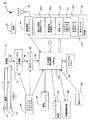
図1は、埋め込み型心臓救済器5及び外部装置7から成る監視システム10の1つの実施形態を示している。電池を動力源とする心臓救済器5は電子回路を含み、それは急性心筋梗塞又は不整脈といった心臓事象を検出できる及びその事象が起こったとき患者に警告できる。心臓救済器5はあとで読み取るために患者の電気記録図を保存でき、無線信号53を外部装置7へ送信し、外部装置7からの無線信号54を受信できる。心臓救済器5の機能は図4を用いて詳細に説明される。
FIG. 1 shows one embodiment of a
心臓救済器5は2つのリード線12及び15を有し、それらは周囲が絶縁のマルチワイヤ導電体を有する。リード線12は2つの電極13及び14で示される。リード線15は皮下電極16及び17を有する。実際、心臓救済器5はわずか1つのリード線又は3つのリード線を利用し、各リード線はわずか1つの電極又は8つの電極を有する。さらに、電極8及び9は心臓救済器5の外側表面に設置され、いかなるワイヤも心臓救済器5の外側に設置されることはない。
The
図1のリード線12は、好ましくは患者の脈管系を通って右室心尖に設置される電極14とともに設置される。電極13側のリード線12は右心室又は右心房又は上大静脈に設置され、ペースメーカー及び埋め込み型冠状動脈除細動器(ICDs)用のリード線の設置と同様である。心臓救済器5の金属製ケース11は、活性電極である電極13及び/又は14の一方又は両方とともに中立電極としての機能を果たす。電極13及び14が複極式電極として使用されることも考えられる。代替案として、図1のリード線12は好ましくは患者の脈管系を通って左室心尖に設置される電極14とともに設置される。電極13は左心房に設置される。
The
リード線15は好ましくは任意の場所の皮下に設置され、そこでは電極16及び/又は17が心臓の電気的活動を示す良好な電気記録図信号を提供する。再びこのリード線15に対して、心臓救済器5のケース11は中立電極であり、電極16及び/又は17は活性電極である、又は電極16及び17は複極式電極として一緒に機能する。心臓救済器5は、心臓救済器5が中立電極である場合、たった1つのリード線とわずか1つの活性電極で動作できる。ここで記述される監視システム10は、2つの電極だけで難なく動作できる。
The
皮下のリード線15を使用する心臓救済器5の1つの実施形態は電極17を有し、それは患者の左側の皮膚の下に設置される。これは患者の左脇の下、2インチから20インチの間に設置されるのが最良である。心臓救済器のケース11は中立電極として作用し、通常患者の胸の左側の皮膚の下に埋め込まれる。
One embodiment of a
図1はまた外部装置7を示し、それはアンテナ70を有する医者のプログラマ68、充電器166を含む外部警報システム60から成る。外部装置7は心臓救済器5と相互作用する手段を提供する。これらの相互作用は心臓救済器5のプログラミング、心臓救済器5により収集されたデータの検索及び心臓救済器5により発生する警報の処理を含む。
FIG. 1 also shows an
図1に示される医者プログラマ68の目的は、埋め込み型の心臓救済器5の動作パラメータを設定する及び/又は変更すること、及び保存された電気記録図セグメントのような心臓救済器5のメモリに保存されているデータを読み取ることである。これは、無線信号54をプログラマ68から心臓救済器5へ送信すること及び無線信号53による心臓救済器5からプログラマ68への遠隔測定を受信することにより達成される。ラップトップ型コンピュータが医者プログラマ68として使用されるとき、心臓救済器5と通信する無線トランシーバへの接続が必要となる。こうしたトランシーバは、USB、シリアルポート又はパラレルポートといった標準インターフェースを経由して接続される又はラップトップのPCMCIAカードスロットに挿入される。ラップトップ上の画面は医者が心臓救済器5と通信する際における案内を提供する。また、画面は心臓救済器5から読み出される実時間の及び保存された電気記録図の両方を表示するために使用される。
The purpose of the
図1では、外部警報システム60は患者が操作する開始プログラム55、警報無効ボタン59、パニックボタン52、警報トランシーバ56、警報スピーカー57及びアンテナ161を有し、モデム165を使い通信リンク65を介して緊急医療サービス67と通信できる。
In FIG. 1, the
心臓事象が心臓救済器5により検知される場合、警報メッセージが無線信号53によりアンテナ161を経由して警報トランシーバ56へ送られる。警報が警報トランシーバ56により受信されると、信号58がスピーカー57へ送られる。信号58はスピーカーが外部警報信号51を出し、患者に事象が起こったことを警告する要因となる。外部警報信号51の例は、周期的なブーンという音、一連の音及び/又は患者にどの動作を起こすべきかを指示する口頭メッセージを含む。さらに、警報トランシーバ56は、信号53の性質に左右されて、リンク65を越えて送信信号を送り、緊急医療サービス67と連絡をとる。急性心筋梗塞の検知が警報の原因であるとき、警報トランシーバ56は自動的に心臓発作が起こったことを緊急医療サービス67に報告し、患者を治療する及び病院の緊急治療室に運ぶために救急車が差し向けられる。
If a cardiac event is detected by the
緊急医療サービス67との遠隔通信が可能であり、心臓事象警報が信号53内で送信される場合、モデム165はデータ通信リンク65を構築し、それを越えてメッセージが緊急医療サービス67に送信される。リンク65を越えて送られるメッセージは以下の情報のいずれか又はそのすべてを含む。その情報とは(1)特定の患者が急性心筋梗塞又はその他の心臓事象を有している、(2)患者の名前、住所及び簡単な既往歴、(3)患者がいるところの地図及び/又は方角、(4)基準電気記録図データ及び警報により発生した特定の電気記録図セグメントを含む患者の保存電気記録図、(5)連続した実時間の電気記録図データ、及び(6)心臓発作の際に患者に投与される薬の型及び量に関する患者のかかりつけの医師による処方箋である。緊急医療サービス67が病院の緊急治療室を含む場合、患者が心臓事象を有すること及び患者が緊急治療室に行く途中であるという情報が送信される。この方法では、緊急治療室の医者が患者の到着にあわせ準備することができる。
If remote communication with the emergency
通信リンク65は有線又は無線電話接続であり、警報トランシーバ56が緊急医療サービス67を呼び出すことができる。典型的な外部警報システム60はポケットPC又はPalm Pilot PDAに組み込まれ、その際警報トランシーバ56及びモデム165はコンパクトフラッシュカード、PCMCIAカード、マルチメディア、メモリスティック又は安全なデジタル(SD)カードといった規格化されたインターフェースを有する挿入可能なカードに組み込まれる。モデム165はSierra Air Card 300のような無線モデムである又はモデム165は標準電話回線に接続する有線モデムである。モデム165はまた、警報トランシーバ56と一体化もできる。
患者が操作する開始プログラム55の目的は、患者に心臓救済器5から最も最近捕捉した電気記録図セグメントを外部警報システム60へ送信できる能力を与えることである。これにより電気記録図セグメントが医者に表示される。警報無効ボタン59は心臓救済器5内で発生した内部警報信号及び/又はスピーカー57を通じて出される外部警報信号51を停止させる。
The purpose of the
患者は自分が心臓事象に直面していると感じる場合にパニックボタン52を押す。パニックボタン52は心臓救済器5から外部警報システム60へ無線信号53を経由して最近の及び基準の電気記録図セグメント両方の送信を開始する。外部警報システム60はその後これらのデータをリンク65を経由して緊急医療サービス67に送信し、そこで医者がその電気記録図データを見る。その後遠隔にいる医者が電気記録図データを解析し、患者に折り返し電話してこれが緊急の状態なのか又はその状態はあとで患者の主治医によりいつものように治療できるものなのかどうかについて助言を与える。
The patient presses the
外部警報システム60にあらかじめ設定された限度が存在することが予想される。その限度は、患者が操作する開始プログラム55及び/又はパニックボタンが1日のうち一定回数以上使用されることを防ぐ。それは、患者が心臓救済器5の電池を切れさせることを防ぐためである。無線送信としての外部警報システム60はこれら装置の他の機能的操作と比べて、比較的大量の電力を使う。
It is anticipated that a preset limit will exist in the
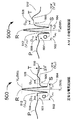
図2は、電極14のような数組の埋め込まれた電極と図3のケース11からの典型的な電気記録図信号と重畳された上昇STセグメント4を示している。電気記録図の様々な部分はP波、Q波、R波、S波及びT波で示される。これらはすべて図2の太実線の部分で示される。正常なSTセグメント3も図2に示される。
FIG. 2 shows several sets of embedded electrodes, such as
急性心筋梗塞が起こるとき、通常図2の細実線で示されるようなSTセグメント4の上昇(又は下降)が存在する。急性心筋梗塞が患者の心筋の重要な部分に起こったことを明らかに示すのが、基準STセグメント3と比較してのSTセグメント4のこのシフトである。
When an acute myocardial infarction occurs, there is usually an elevation (or decline) of ST segment 4 as shown by the thin solid line in FIG. It is this shift of ST segment 4 relative to reference
上昇STセグメント4は急性心筋梗塞の優れた指標ではあるが、心拍数又は心臓壁運動の突然の変化、血栓症又は血液pO2の急激な低下といった他の指標もまた独立した感知手段として使用される又はこれらの信号がSTセグメント4の電圧シフトに加えて使用される。 Although elevated ST segment 4 is a good indicator of acute myocardial infarction, sudden changes in heart rate or heart wall motion, other indicators such as a sharp drop in thrombosis or blood pO 2 may also be used as an independent sensing means Or these signals are used in addition to the ST segment 4 voltage shift.
埋め込まれた電極からの電気記録図により皮膚の表面の電極から得られた心電図信号と比べてSTセグメントシフトがより早く検知できることに留意することが重要である。従って、ここに記述された埋め込まれた電極からの電気記録図は本発明の好ましい実施形態である。 It is important to note that electrograms from the implanted electrodes allow for faster detection of ST segment shifts compared to electrocardiogram signals obtained from electrodes on the surface of the skin. Accordingly, the electrograms from the embedded electrodes described herein are a preferred embodiment of the present invention.
心臓発作が起こるとき、T波が非常に素早く移動することもよく知られている。本発明が比較するとこのT波シフトを過去1分から5分の時間で検知できることが予想される。 It is also well known that T waves move very quickly when a heart attack occurs. In comparison with the present invention, it is expected that this T-wave shift can be detected in the past 1 to 5 minutes.
冠状動脈の狭窄を有する患者が比較的激しい運動をすると、心拍数が上昇して運動誘発性虚血に発展し、電気記録図のSTセグメントがシフトする原因となるということが予想される。これは特にステント移植を伴う又は伴わないバルーン血管形成を受けた患者にあてはまる。こうした患者は、運動中に図1の心臓救済器5が警報を作動させた場合、それは心臓の動脈の1つに動脈狭窄の進行があることを示しているということを主治医により知らされる。こうした患者は、すべての運動をただちにやめるように助言され、患者の心拍数がゆっくりになるにつれて警報信号が消えていく場合、患者は都合のつき次第医者に診てもらうべきである。患者の心拍数が通常範囲にまでゆっくりになっても警報信号が消えない場合は、その後心臓救済器は警報信号を変更して患者は直ちに診療してもらうべきだということを知らせる。前述したように、心臓救済器5は運動が原因の虚血である場合に発生する信号と比較して、心臓発作の場合には異なる信号を発する。
It is expected that if a patient with coronary stenosis exercises relatively hard, the heart rate will increase and develop into exercise-induced ischemia, causing a shift in the ST segment of the electrogram. This is especially true for patients who have undergone balloon angioplasty with or without stent implantation. Such a patient is notified by the attending physician that if the
STセグメントの電圧シフトの間に体験する心拍数と心拍数の変化率はどの警報が心臓救済器5により作られるべきかを示すのに使用できることも予想される。具体的には、正常な心拍数に近いSTセグメントシフトは急性心筋梗塞を示す。上昇心拍数(例えば、100bpm以上)が存在するときのSTセグメントシフトは、一般に冠状動脈の狭窄が進行していることを示す。いかなる場合も、心臓救済器5からの警報の原因となるのに十分なSTセグメントのシフトが起こった場合、患者はすぐに診療をうけ、警報の原因を確定すべきである。
It is also envisioned that the heart rate experienced during the voltage shift of the ST segment and the rate of change of the heart rate can be used to indicate which alert should be generated by the
患者の病状に左右されて、激しい運動が長い距離を走ること又は単に階段をあがることと同じくらい活動的であることを理解されたい。心臓救済器5がステント移植を受けた患者に埋め込まれたあと、患者はストレステストを受けて、STセグメントシフトのレベルを決定しなければならない。STセグメントシフトのレベルは患者が実現できる運動のうち最も高いレベルと関係する。患者の心拍数はその後記録され、図5から図9に記載される心臓救済器の検知用閾値はプログラム制御されて運動中に観測されるSTセグメントシフトでは警報しない。その後、のちに患者が所定の心拍数で又は心拍数範囲内でSTセグメントの上昇シフトに直面する場合、その後狭窄を示す警報が発生するようにプログラム制御される。こうした警報の発生はいくつかの冠状動脈の狭窄が進行していることを示し、可能的にステント移植を含む血管形成が必要かどうかを決定するために血管造影が必要となる。
It should be understood that, depending on the patient's condition, strenuous exercise is as active as running long distances or simply going up stairs. After the
急性心筋梗塞が原因である過度のSTシフトに関連する警報信号は、運動中に進行する虚血に関連する「SEE DOCTOR」警報手段とは全く異なる。例えば、SEE DOCTOR警報信号は音声信号であり、5秒から10秒ごとに1回発生する。異なる警報信号、例えば3秒から5秒ごとに3回ブザーが鳴る音声信号は、急性心筋梗塞のような重大な心臓事象を示すために使用される。似ている警報信号の時間的調節は通常図4の警報サブシステム48により発生する内部警報信号及び外部警報システム60により発生する外部警報信号の両方に使用される。
The alarm signal associated with excessive ST shift due to acute myocardial infarction is quite different from the "SEE DOCTOR" alarm means associated with ischemia progressing during exercise. For example, the SEE DOCTOR warning signal is an audio signal and is generated once every 5 to 10 seconds. Different alarm signals, for example, a sound signal that beeps three times every three to five seconds, are used to indicate a significant cardiac event, such as an acute myocardial infarction. Similar alarm signal timings are typically used for both the internal alarm signal generated by the
いかなる場合も、患者はどの信号がこれらの異なる状況に対して発生するかを認識するよう教えられ、それにより患者は急性心筋梗塞が示される場合は即座に対応できるが、狭窄の進行又はいくつかの他の危険度の低い状況が示される場合は緊急の対応をとることができない。当然のことであるが、他の明らかに異なる音声警報パターンは心房細動、心房粗動、PVC’s、PAC’sなどといった異なる不整脈に使用される。図1の医者プログラマ68の機能は、異なる警報信号パターンをプログラム制御すること、これら様々な心臓事象の任意の1つ又はそれ以上に対して、心臓救済器の関連する警報信号の検知及び/又は発生を可能にする又は無効にすることである。また、音声警報、振動又は電気的刺激警報の強度は、異なる患者の必要に適合するように調節される。患者が異なる警報信号に慣れるために、本発明のプログラマ68は異なる警報信号のそれぞれを発生させる及び停止させる機能を有する。
In any case, the patient is instructed to recognize which signals occur for these different situations, so that the patient can respond immediately if an acute myocardial infarction is indicated, but the progression of stenosis or some If other low-risk situations are indicated, emergency action cannot be taken. Of course, other distinctly different voice alert patterns are used for different arrhythmias such as atrial fibrillation, atrial flutter, PVC's, PAC's, and the like. The functions of the
図3はケース11及びプラスチックヘッダー20を有する心臓救済器5の平面図である。ケース11は電池22及び電子機器モジュール18を含む。この型のパッケージはペースメーカー、埋め込み型除細動器及び埋め込み型細胞刺激装置用で知られている。プラスチックヘッダー20を通じて設置される導電体は電子機器モジュール18と導線12及び15を接続する。導線12及び15はそれぞれ電極14及び17を有する。図1のケース上の電極8及び9は図3には示されていない。当然のことながら、心臓救済器5は2つの電極だけで機能でき、そのうちの1つはケース11である。電極8、9、13、14、16又は金属ケース11のような図1及び図3に示される電極の異なる構成のすべては、心臓救済器5で使用できる様々な電極配置の可能性を示唆するためだけに示される。
FIG. 3 is a plan view of the
金属ケース11上では、絶縁ディスク32上に取り付けられる導電ディスク31が、皮下に電気的刺激を与えて患者に急性心筋梗塞が起こっていることを警告するために又は独立した電極として作用するために使用できる。
On the metal case 11, the
図4は電池22を伴う心臓救済器5のブロック図である。電極14及び17はワイヤ12及び15でそれぞれ増幅器36に接続する。増幅器36はまた中立電極として作用するケース11とも接続する。2つ又はそれ以上の電極12及び15がここに示されるので、増幅器36は多重チャンネル増幅器である。増幅器36から増幅された電気記録図信号37はその後アナログ−デジタル変換器41によりデジタル信号38に変換される。デジタル電気記録図信号38はファースト・イン・ファースト・アウト(FIFO)方式でメモリ42に格納される。中央演算処理装置(CPU)44として図4に示されるプロセッサ手段はランダムアクセスメモリ(RAM)47として図4に示されるメモリ手段と結合し、FIFO42に保存されるデジタル電気記録図データ38をプログラムメモリ45に保存されるプログラミング指示に従って処理できる。このプログラミング(すなわちソフトウェア)により心臓救済器5には急性心筋梗塞のような心臓事象の発生を検知することができる。
FIG. 4 is a block diagram of the
クロック/タイミングサブシステム49は、心臓事象を検知した絶対的な又は相対的な時間の打刻を含む心臓救済器5のタイミングをとるための特別な作動をする手段を提供する。クロック/タイミングサブシステム49はまた、心臓救済器5の構成部品を電気記録図信号の収集及び処理の時間の間に低電力のスタンバイモードの状態にさせることにより、省力化を容易にする。こうした循環省力技術は、しばしば埋め込み型ペースメーカー及び除細動器に使用される。代替実施形態では、クロック/タイミングサブシステムは中央演算処理装置44により作動するプログラムサブルーチンにより提供される。
The clock /
本発明の進歩した実施形態では、クロック/タイミング回路49は第1の周期(例えば20秒)を数え、その後アナログ−デジタル変換器41及びFIFO42がデータ保存を始めることができる。第2の周期(例えば10秒)後、タイミング回路49は低電力スタンバイモードからCPU44を作動させる。CPU44はその後非常に短い時間(通常1秒以下)で10秒分のデータを処理し、低電力モードに戻る。これによりCPU44の稼働・非稼働サイクルを可能にする。CPU44はしばしば1分間に2秒以下で最大電力を消費し、一方では1分間に20秒ずつ実際に電気記録図データを収集する。
In an advanced embodiment of the present invention, clock /
本発明の好適な実施形態では、RAM47は3セットの電気記録図セグメントを保存するための特別な記憶域を含む。これらは最近記録した電気記録図セグメントを最後の2分から10分を保存する最近の電気記録図記憶領域472であり、それにより心臓事象が始まる直前の周期に至る電気記録図データが、図1の医者プログラム68を使用する患者の主治医によりのちに調べられることができる。例えば、最近の電気記録図記憶領域472は、8つの10秒長の電気記録図セグメントを含み、それらは最後の4分で30秒ごとに捕捉される。
In a preferred embodiment of the present invention, RAM 47 includes special storage for storing three sets of electrogram segments. These are the recent
基準電気記録図メモリ474は、1又はそれ以上の日にわたるあらかじめ設定された時間に収集された基準電気記録図セグメントの記憶領域を提供する。例えば、基準電気記録図メモリ474は最後の日の1時間ごとに10秒間の24の基準電気記録図セグメントを含む。
事象メモリ476はRAM47の最大部分を占める。事象メモリ476は最近の電気記録図メモリ472及び基準電気記録図メモリ474のように定期的に上書きされないが、通常患者の主治医が図1のプログラマ68を使って読み取るまで維持される。急性心筋梗塞を示す過度のSTシフトのような心臓事象がCPU44により検知されるとき、基準及び最近の電気記録図メモリ472及び474の全体内容のすべて(又は一部)が通常事象メモリ476にコピーされ、あとで医者が調査できるように事象以前のデータを保存する。
The
RAM47はまた、プログラム制御できるパラメータ471及び計算された基準データ475用のメモリ部分も含む。プログラム制御できるパラメータ471は正常な及び上昇した心拍数範囲の上限と下限、及びプログラムメモリ45に保存される心臓事象の検知処理に関連する医者がプログラム制御できるパラメータを含む。計算された基準データ475は基準電気記録図メモリ474に保存される基準電気記録図セグメントから抽出された検知パラメータを含む。計算された基準データ475及びプログラム制御できるパラメータ471は通常事象メモリ476に保存され、続いて心臓事象を検知する。RAM47はまた、患者データ473を含む。それは患者の名前、住所、電話番号、病歴、保険情報、主治医の名前、及び異なる心臓事象の際に開業医により処方された異なる投薬に関する特別な処方箋を含む。
RAM 47 also includes a memory portion for
心臓救済器5がまた米国特許番号6,240,049でFischellにより記載された心臓救済器システムに似たペースメーカー回路170及び/又は除細動器回路180も含むことが予想される。
It is anticipated that the
警報サブシステム48は心臓救済器5の内部警報信号を作り出す回路及びトランスデューサを含む。内部警報信号は機械的振動、音声又は皮下の電気的刺激又は衝撃である。
The
アンテナ35を伴う遠隔測定サブシステム46は心臓救済器5に図1の外部装置7への及びからの2方向無線通信手段を提供する。RF Microdevice, Inc.により作られたAsh transceiver hybridsのような無線周波数トランシーバチップセットが存在することにより、患者から10メートルまでの範囲を越えてこうした2方向の無線通信を容易に提供できる。通常ペースメーカー及び除細動器に使用されるような短い範囲の遠隔測定も心臓救済器5に適用できることが予想される。ブルートゥース及び802.11a又は802.11bのような標準無線プロトコルが周辺装置の幅広いグループと通信できるように使用されることが予想される。
磁石センサ190は心臓救済器5に組み込まれる。磁石センサ190の重要な効用はプログラミング及び埋め込みの直前に心臓救済器5を作動させることである。これにより工場で包装される時間から心臓救済器5が埋め込まれる日までの無駄な電池寿命を減らすことができる。
The
図5は図1から図4の心臓救済器5による心臓事象検知用の心臓信号処理プログラム450の操作をブロック図形式で示している。心臓信号処理プログラム450は多くの検知プログラムの一例であり、こうした多くの検知プログラムの指示は図4に示される心臓救済器5のCPU44により使用されるプログラムメモリ45に存在する。心臓信号処理プログラム450の主要部分は工程451から始まる。そこでは事象カウンタ「k」がゼロに設定される。それは検知される事象がないことを示す。次に工程452で、心臓救済器5がX秒スリープするように言われる。ここでのスリープという用語はX秒の間、心臓救済器5が低電力スタンバイモード(可能であれば)に置かれる又はさもなければ工程453に移行する前にX秒の時間単に待つということを意味する。工程452に続く工程453は電気記録図セグメントを有し、それは図4のFIFOバッファ42に捕捉されたY秒の電気記録図データを表す。σは1秒ごとのサンプルにおけるデータサンプリング率であり、従って工程453で収集されたサンプルの総数はσ×Yである。Xは5秒から5分の間で、好ましい値としては20秒という時間であることが予想される。Yは3秒から30秒の間で、好適な値としては10秒である。σは通常1秒につき100から500例の間であり、好ましくは1秒に200例である。
FIG. 5 shows in block diagram form the operation of the cardiac
Y秒の電気記録図データが捕捉されたあと、工程454では、最も最近の電気記録図セグメントを表すY秒の電気記録図データが図4の最近の電気記録図メモリ472に送信される。このとき、データの処理及び解析が始まる。図面についてのこの詳細な記載はこれより、「Y秒長の電気記録図セグメント」は最も最近収集されたY秒の電気記録図データをいい、工程453により捕捉される及び工程454により最近の電気記録図メモリ472に送信される。「最近の電気記録図セグメント」という用語は、最近の電気記録図メモリ472に保存された電気記録図セグメントのすべてをいう。例えば、4分間に30秒の間隔で捕捉された10秒長の最近の電気記録図セグメントは8つ存在する。
After the Y second electrogram data has been captured, at
Y秒長の電気記録図セグメントの収集に続く第1の処理工程は工程455であり、それは最も最近のY秒長の電気記録図セグメントのR波間の間隔を測定する。これらのR-R間隔はその後Y秒長の電気記録図セグメントの平均心拍数及びR-R間隔の変化を計算するために使用される。平均心拍数がプログラム制御された心拍数の下限plowを下回る又はプログラム制御された心拍数の上限phighを上回る場合、「範囲外」と考えられ、Hi/Low心拍数サブルーチン420(図9参照)が作動して、状況に正しく反応する。
The first processing step following the collection of the Y second electrogram segment is
Y秒長の電気記録図セグメント内のR-R間隔の変化がプログラム制御された限度以上である場合、高/低心拍数サブルーチンも作動する。これは本発明の重要な特徴である。なぜなら二重の鼓動のようなPVC’s及び不規則な心臓の鼓動は、安定した心臓の鼓動で最も良く働くSTシフト検知アルゴリズムにおけるエラーの原因となるからである。本発明の1つの実施形態は、Y秒長の電気記録図セグメントにおける2つの最も短いR-R間隔と2つの最も長い間隔を比較することにより不規則な心拍数を認識する。2つの最も短いR-R間隔の両方と2つの最も長いR-R間隔の平均との間の差異がプログラム制御されたパーセンテージαより大きい場合、不規則な心拍数が認められる。例えばプログラム制御されたパーセンテージαが25%であり、それにより2つの最も短いR-R間隔がそれぞれ25%以上で、2つの最も長いR-R間隔の平均より小さい場合、その後の心拍数は不規則である。長めの時間Yが電気記録図セグメントの収集に使用される場合、示された不規則な心拍数に対して3つ又はそれより「短い」拍動を必要とすることが予想される。短すぎない任意の拍動は正常な拍動として工程455により分類される。plow、phigh及びαはプログラム制御可能なパラメータであり、通常心臓救済器5のプログラミング中にプログラマ68を使用して設定される。plow及びphighの通常の値はそれぞれ1分間あたり50拍動及び140拍動である。
If the change in the RR interval within a Y second long electrogram segment is greater than a programmed limit, the high / low heart rate subroutine is also activated. This is an important feature of the present invention. This is because PVC's and double heartbeats and irregular heartbeats cause errors in the ST shift detection algorithm that work best with a stable heartbeat. One embodiment of the present invention recognizes an irregular heart rate by comparing the two shortest RR intervals with the two longest intervals in a Y second long electrogram segment. If the difference between both the two shortest RR intervals and the average of the two longest RR intervals is greater than the programmed percentage α, an irregular heart rate is noted. For example, if the programmed percentage α is 25%, so that the two shortest RR intervals are each greater than or equal to 25% and less than the average of the two longest RR intervals, then the heart rate is irregular. If a longer time Y is used to collect electrogram segments, it is expected that three or less "short" beats will be required for the indicated irregular heart rate. Any beat that is not too short is classified by
工程455で検査したところ心拍数が高くもなく、低くもなく、不規則でもない場合、心臓信号処理プログラム450は工程456へ移行する。そこでは平均心拍数がplow及びpelevatedの間のプログラム制御された正常範囲と比較される。このときpelevatedは「正常範囲」(例えば1分間に80拍動)の上限を画定する上昇した心拍数の限界である。患者の心拍数が上昇するが範囲外(すなわちphigh以上)ではない場合、患者は運動をしており、虚血サブルーチン480により上昇心拍数の間の異なる心臓救済器の検知基準に対して、急性心筋梗塞の偽陽性検知の減少及び運動誘発性虚血の検知が可能となる。虚血サブルーチン480の1つの実施形態の例は図10に示されている。
If the heart rate is not high, low, or irregular as determined at
上記明細書で低心拍数plow、高心拍数phigh及び上昇心拍数pelevatedを記述しているが、心拍数(すなわち拍動/秒)の代わりに、限度及び意思決定が、R波からR波(R-R)間隔で設定でき、低い、高い及び上昇限度はR-R間隔のためであり、秒/拍動、ミリ秒/拍動又は例/拍動で表現される。 Although the above specification describes a low heart rate p low , a high heart rate p high and an elevated heart rate p elevated , instead of heart rate (ie beats / sec), the limits and decisions are made from the R-wave. It can be set in R-wave (RR) intervals, the low, high and rising limits are for the RR interval, expressed in seconds / beat, milliseconds / beat or examples / beat.
工程456で患者の平均心拍数が「正常」範囲内にある場合、その後プログラム450は工程457に移行する。そこでは、プログラム450がN拍動のうちのMでの過度のSTシフトをさがし、過去U±W分に収集された基準電気記録図セグメントと比較する。Uは1分から48時間の任意の時間であるが、日常サイクルであるU=24時間とすることが好ましい実施形態である。Wは基準データが保存された時間の半分の間隔であり、10秒から12時間の間の任意の時間である。24時間のUに対して、好ましい設定は30分に等しいWを有し、それにより現在のY秒長の電気記録図セグメントは常に24±1/2時間前からの基準電気記録図セグメントと比較される。これはまた、基準電気記録図セグメントが保存され及び処理されて2倍のW(2W)の間隔で検知パラメータで抽出するということを意味する。すなわち、Wが30分であるとき、その後基準データは1時間に1回保存される及び処理される。Mは1から30のうちの任意の数であり、NはMから100のうちの任意の数である。通常使用されるM及びNの例は8拍動のうちの6である。最初の8拍動は通常、工程453及び工程454で収集されたY秒の電気記録図セグメントに2nd波を含む拍動であると予想される。
If the average heart rate of the patient is within the “normal” range at
工程457におけるSTシフト検知の代替案は、心臓発作が起こった場合に素早くピーク又は平均振幅を変更できるT波を処理することである。しかしT波は通常状況下でもゆっくりとその振幅を変化させ、そのためT波シフト検知器はT波の前のSTセグメントを使用する検知器のそれよりさらに短い時間Uを必要とする。検知器がこうしたT波シフト、すなわちSTセグメントのT波部分の電圧シフトを検査する場合、その後基準に対して検査することが望ましい。その際Uが1分から30分の間でWが15秒から15分の間である。例えば、U=3分及びW=15秒がすばやく変化するT波を捕捉するのに好ましい設定である。これにより、図4の最近の電気記録図メモリに保存される最近の電気記録セグメントをT波シフト検知用の基準電気記録図セグメントとして使用できる。図1のプログラマ68により患者の主治医が心臓救済器5をプログラム制御してSTセグメントシフト又はT波シフト検知器がそれら自身で、又は同時に一緒に使用できるということが予想される。両方が使用される場合、その後プログラマ68により患者の主治医は、陽性検知がもたらされるのが一方の技術が事象を検知する場合なのか又は両方が事象を検知する場合なのかを選択できる。
An alternative to ST shift detection in
工程457で平均心拍数が正常範囲である、不規則でない及び心臓事象検知がない場合(すなわち、電気記録図信号が患者の「正常」心臓信号を示す)、心臓信号処理プログラム450は工程458で、基準データが捕捉された最後の時から2W分の間隔より大きいかどうかを検査する。2Wより大きい場合、図7の基準パラメータ抽出サブルーチン440が作動する。
If the average heart rate is in the normal range, irregular, and there is no cardiac event detection at step 457 (ie, the electrogram signal indicates the patient's "normal" heart signal), the heart
パラメータX、Y、U及びWはプログラム制御できるパラメータ471とともに図4のRAM47に保存される。これらのパラメータは心臓救済器5を製造する時に恒久的に設定される又は図1のプログラマ68を通じてプログラム制御される。基準電気記録図メモリ474に保存される基準電気記録図セグメントから抽出された心臓事象検知の計算された基準は、RAM47の計算された基準データメモリ475に保存される。
The parameters X, Y, U and W are stored in the RAM 47 of FIG. These parameters are set permanently when manufacturing the
STシフト検知器だけを使用する心臓信号処理プログラム450の典型的な構成は、X=20秒のスリープを使用し、続いてY=10秒長の電気記録図セグメントを収集する。患者の心拍数が1分間に50拍動から80拍動の間の正常範囲にある場合、工程457は24±1/2時間に収集された基準データと比較して8拍動のうち6拍動のSTセグメントの過度なシフトを検査する。
A typical configuration of a cardiac
工程457でN拍動のうちMで過度のSTシフトが検知された場合、ST検証サブルーチン460が作動し、検知された事象が電気記録図の一時的な変化ではないことを確認する。
If an excessive ST shift is detected in M of the N beats in
ST検証サブルーチン460は工程461から始まる。その際最近収集されたY秒長の電気記録図セグメントが、図4の事象メモリ476に保存される。患者の主治医があとから調べるためである。
The
STシフト検証サブルーチン460はその後、事象カウンタkを1ずつ増加し(工程462)、その後kが3に等しいかどうか(すなわち、3つの事象が警報のきっかけとなる)を検査する(工程463)。k=3である場合、その後図8に示される警報サブルーチン490が作動する。従って、重大な心臓事象の陽性検知があったことを明らかにする。図11はk=3及び警報サブルーチン490の作動を導く状況の組み合わせの例を示している。
The ST
工程463は警報サブルーチン490を作動する状況としてk=3かどうかを検査することが示されているが、要求される事象の数はk=1からk=20のプログラム制御できるパラメータである。k=20より高い可能的値でも、偽陽性検知を避けるために使用される。心臓発作の開始から治療センターへの到着までの現在の平均時間が3時間では、患者を30分以内に容易に治療センターに届けることができる装置に対する2、3分の遅れは、それで検知の信頼性が改善する場合には貴重である。
Step 463 is shown to check if k = 3 as a condition for activating
工程463でkが3より小さい場合、その後STシフト検証サブルーチン460は工程464でZ秒のスリープに入り、続いて図4の最近の電気記録図メモリ472の次の場所に新たなY秒長の電気記録図セグメントを収集する(工程465)及び保存する(工程466)。Z秒は工程452で使用されるX秒とは異なり、STシフト検証サブルーチン460が主要プログラムより長い(又は短い)間隔を調べることができ、それにより工程457の陽性検知を最も良く検証する。ここでのスリープという用語は、工程452と同じ含意を有する。本発明の好ましい実施形態はZ=X=20秒を使用する。
If k is less than 3 in
その後STシフト検証サブルーチン460は、工程467で範囲外の又は不規則な心拍数を検査する。工程455に関して上述したように、範囲外の心拍数とは、Y秒長の電気記録図セグメントの平均心拍数が心拍数の下限plowを下回る又は心拍数の上限phighを上回ることを意味する。
The ST
心拍数が範囲外又は不規則である場合、工程467は高/低サブルーチン420を開始する。心拍数が範囲外ではない又は不規則ではない場合、その後工程468は上述した工程456と同様に心拍数が正常なのか又は上昇しているかどうかを検査する。心拍数が上昇している場合、虚血サブルーチン480が作動する。心拍数が変化しているかどうかを検査する理由は、急性心筋梗塞が頻脈又は細動からの高心拍数を引き起こすからである。頻脈及び細動はSTシフトを隠すが、その検知が事象カウンタkを増加させる重大な心臓事象である。
If the heart rate is out of range or irregular, step 467 initiates a high /
心拍数が正常範囲(すなわち上昇していない)場合、その後工程469は過去U±W分に抽出された基準データと比較してY秒長の電気記録図セグメントのN拍動のうちのMにおける過度のSTシフト及び/又はT波シフトを調べる(工程457と同様)。過度のSTシフト及び/又はT波シフトも見られない場合、サブルーチン460は心臓信号処理プログラム450の工程458に戻り、その後最終的に工程451、つまり心臓信号処理プログラム450の始まりに戻る。工程451ではkは0に後退し、それによって3(k)の連続するY秒長の電気記録図セグメントで心臓事象が検知される場合に限り、警報サブルーチン490が作動する。本発明の好ましい実施形態では、工程457及び工程469は「正常な」N拍動のうちMだけを調べ、工程455で決定された短すぎる任意の拍動は無視する。
If the heart rate is in the normal range (ie, not rising), then step 469 compares at M out of N beats of the electrogram segment Y seconds long compared to the reference data extracted in the past U ± W minutes. Check for excessive ST shift and / or T wave shift (similar to step 457). If no excessive ST and / or T-wave shifts are found,
基準データは、心拍数が正常範囲内にあり、N拍動のうちのMに過度のSTしシフト又はT波シフトがないときに限り抽出されるという点に留意することが重要である。本発明の1つの実施形態では、これは基準パラメータ抽出サブルーチン440に個々に過度のSTシフト及び/又はT波シフトを示さない正常拍動だけを処理させることによりさらに改良される。
It is important to note that the reference data is only extracted when the heart rate is within the normal range and there is no excessive ST shift or T wave shift in M of the N beats. In one embodiment of the present invention, this is further improved by having the reference
図6は電気記録図セグメントの単一の正常拍動500とAMI電気記録図セグメントの単一の拍動500’の特徴を示している。AMI電気記録図セグメントの単一の拍動500’は正常拍動500と比較して重大なSTセグメントシフトを有する。こうしたSTセグメントシフトはAMIの間の冠状動脈の閉塞に続いて数分以内に起こる。拍動500及び500’はP、Q、R、S及びTと表示される典型的な心臓拍動波の要素を示す。拍動500のような拍動の定義は、電気記録図セグメントのサブセグメントであり、厳密に1つのR波を含み、R波の前にP及びQ要素を、R波に続いてS及びT波要素を含む。
FIG. 6 illustrates the features of a single
検知アルゴリズムにおいて、拍動500及び500’に関係する異なるサブセグメント、要素及び計算値がここに明記されている。拍動500のR波のピークは時間TR(509)で発生する。PQセグメント501及びSTセグメント505は正常拍動500のサブセグメントであり、以下の
a. PQセグメント501は継続時間DPQ(506)を有し、時間TR(509)前TPQ(502)ミリ秒から開始する。
b. STセグメント505は継続時間DST(508)を有し、時間TR(509)後TST(502)ミリ秒から開始する。
といった時間TR(509)に関した時間に置かれる。
In the detection algorithm, the different sub-segments, elements and calculations related to
a.
b.
Is set to the time related to the time T R (509).
PQセグメント501’及びSTセグメント505’は拍動500’のサブセグメントであり、以下の
c. PQセグメント501’は継続時間DPQ(506)を有し、時間T’R(509’)前TPQ(502)ミリ秒から開始する。
d. STセグメント505’は継続時間DST(508)を有し、時間T’R(509’)後TST(502)ミリ秒から開始する。
といった時間T’R(509’)に関した時間に置かれる。
The
c. The
d. ST segment 505 'has duration D ST (508) and starts at T ST (502) ms after time T' R (509 ').
At a time related to the time T ′ R (509 ′).
STセグメント505と505’及びPQセグメント501と501’は患者の心臓からの電気信号のサブセグメントの例である。R波及びT波もまたサブセグメントである。
破線VPQ(512)及びVST(514)は正常拍動500に対するPQセグメント501及びSTセグメント505それぞれの平均電圧振幅を示している。同様に、破線V’PQ(512’)及びV’ST(514’)は拍動500’に対するPQセグメント501’及びSTセグメント505’それぞれの平均電圧振幅を示している。正常拍動500の「ST偏差」ΔV(510)及びAMI電気記録図拍動500’のST偏差ΔVAMI(510’)は以下のように定義される。
ΔV(510)=VST(514)−VPQ(512)
ΔVAMI(510’)=V’ST(514’)−V’PQ(512’)
Dashed lines V PQ (512) and V ST (514) indicate the average voltage amplitude of
ΔV (510) = V ST (514) −V PQ (512)
ΔV AMI (510 ′) = V ′ ST (514 ′) − V ′ PQ (512 ′)
拍動500及び500’はR波のピークからの同じ時間オフセットTPQとTST及び同じ継続時間DPQとDSTを使用して解析されることに留意すべきである。この例では、拍動500及び500’は同じ継続時間(すなわち同じ心拍数)である。パラメータTPQ、TST、DPQ及びDSTは通常心臓救済器5が埋め込まれるときに患者の主治医により図1のプログラマで設定され、それにより患者の電気記録図信号の形態と正常心拍数が最良に合致する。VPQ(512)、VST(514)、VR(503)及びΔV(510)は拍動500に対する1拍動あたりの心臓信号パラメータの例である。
It should be noted that beats 500 and 500 'are analyzed using the same time offsets T PQ and T ST from the peak of the R-wave and the same durations D PQ and D ST . In this example, beats 500 and 500 'are of the same duration (ie, the same heart rate). The parameters T PQ , T ST , D PQ and D ST are usually set by the patient's physician in the programmer of FIG. 1 when the
時間オフセットTPQ(502)とTST(504)及び継続時間DPQ(506)とDST(508)の値を固定することは効果的であるが、時間オフセットTPQとTST及び継続時間DPQとDSTが心臓救済器5により自動的に調節されて、患者の心拍数の変化を明らかにすることが予想される。心拍数が患者の正常心拍数と比較して増加する又は減少する場合、時間オフセットTPQ(502)とTST(504)及び/又は継続時間DPQ(506)とDST(508)が拍動間のR-R間隔又は電気記録図セグメントの平均R-R間隔に左右されて変化することが予想される。これを行う単純な技術はR-R間隔の変化に比例して時間オフセットTPQとTST及び継続時間DPQとDSTを変更する。例えば、患者の正常心拍数が1分間に60拍動である場合、R-R間隔は1秒である。1分に80拍動の場合はR-R間隔は0.75秒であり、25%減少する。これによりTPQ、TST、DPQ及びDSTの値に自動的に25%の減少が生まれる。代替案として、TPQ、TST、DPQ及びDSTの値は20というあらかじめ設定された心拍数範囲までにそれぞれ固定される。一方の場合、装置が埋め込まれた後、患者の主治医が図1のプログラマ68を通じて心臓救済器5からプログラマ68へ最近の電気記録図メモリ472からの最近の電気記録図セグメントをダウンロードすることが予想される。その後医者はプログラマ68を使用してダウンロードした最近の電気記録図セグメントの心拍数に対するTPQ、TST、DPQ及びDSTの値を選択する。その後プログラマ68は医者が各心拍数範囲に対するTPQ、TST、DPQ及びDSTの値を手作業で分類する又は心臓救済器5に自動的に、心臓救済器5により将来収集される任意の電気記録図セグメントの各拍動に対するR-R間隔を基礎とするTPQ、TST、DPQ及びDSTの値を調節させるかのどちらかを選択できるようにする。オフセット時間TPQ及びTSTだけが自動的に調節され、継続時間DPQ及びDSTは固定されて、それによりSTセグメント及びPQセグメントの平均値VPQ(512)、VST(514)、V’PQ(512’)及びV’ST(514’)が常に平均化するため同数のデータ例を使用することも予想される。
While it is effective to fix the values of the time offsets T PQ (502) and T ST (504) and the durations D PQ (506) and D ST (508), the time offsets T PQ and T ST and the duration It is expected that D PQ and D ST will be adjusted automatically by the
正常拍動500に対するST偏差510を計算するのに使用される一連の工程の例は以下の通りである。
1.拍動500に対するR波のピークの時間TR(509)を確認する。
2.以前のR波からの時間を計算し、その時間を使用してTPQ、TST、DPQ及びDSTの値を調べる又は計算する。
3.時間(TR−TPQ)と時間(TR−TPQ+DPQ)間のPQセグメント501の振幅を平均化してPQセグメントの平均振幅VPQ(512)を作り出す。
4.時間(TR+TST)と時間(TR+TST+DST)間のSTセグメント505の振幅を平均化してSTセグメントの平均振幅VST(514)を作り出す。
5.VST(514)からVPQ(512)を引いて拍動500に対するST偏差ΔV(510)を作り出す。
An example of the sequence of steps used to calculate the
1. The peak time T R (509) of the R wave with respect to the
2. Calculate the time since the previous R-wave and use that time to look up or calculate the values of T PQ , T ST , D PQ and D ST .
3. Creating a time (T R -T PQ) and the time (T R -T PQ + D PQ ) average PQ segment by averaging the amplitudes of the
4. The amplitude of the
5. Subtract V PQ (512) from V ST (514) to create an ST deviation ΔV (510) for
ここには1つだけの正常拍動500が示されているが、通常は複数の拍動が存在し、それは図4の最近の電気記録図メモリ472及び基準電気記録図メモリ474に保存されるY秒長の電気記録図セグメントに格納される。1日のうちの前もって設定された時間間隔で、図5の工程458が基準パラメータ抽出サブルーチン440を作動させる。それは「平均基準ST偏差」ΔVBASEを計算し、少なくとも2つの拍動の基準電気記録図セグメントのST偏差ΔV(510)の平均として定義される。通常は、4拍動から8拍動の基準電気記録図セグメントのST偏差が平均化されて、平均基準ST偏差ΔVBASEを作り出す。
Although only one
1日のうちのあらかじめ設定された時間「i」(およそ2Wの時間間隔)のそれぞれに対して、平均基準ST偏差ΔVBASE(i)が計算されて、計算された基準データメモリ475に保存される。後に最近収集された電気記録図の各拍動のST偏差ΔV(510)と比較するためである。例えば、本発明の好ましい実施形態では、平均基準ST偏差ΔVBASE(i)が1時間に1度収集され、図4の計算された基準データメモリ475に保存される24の値ΔVBASE(i)(ΔVBASE(1)、 ΔVBASE(2)、… ΔVBASE(24))が存在する。単一の拍動最近収集された電気記録図セグメントの過度のSTシフトは、その拍動に対するST偏差ΔVが、およそ24時間前に収集された平均基準ST偏差ΔVBASE(i)から所定の閾値振幅以上シフトするときに検知される。
The average reference ST deviation ΔV BASE (i) is calculated for each predetermined time “i” (time interval of about 2 W) in one day, and is stored in the calculated
所定の拍動のSTシフトは、その拍動に対するST偏差ΔVから適切な平均基準ST偏差ΔVBASE(i)を引くことにより計算される。R-R間隔が1拍動の心拍数が正常範囲にあることを示すと想定すると、その後単一の拍動の過度のSTシフトは(ΔV−ΔV BASE(i))が正常心拍数範囲の正常STシフト閾値Hnormalより大きい場合に検知される。図5の心臓信号処理プログラム450は、警報サブルーチン490が作動する前にこうした過度のSTシフトが3つの連続する最近の電気記録図セグメントのN拍動のうちのMで積極的に認識されることを必要とする。閾値Hnormalは固定値であり、ある期間にわたって変化せず、図1のプログラマ68で心臓救済器5のプログラミングの時間に設定されている。
The ST shift for a given beat is calculated by subtracting the appropriate average reference ST deviation ΔV BASE (i) from the ST deviation ΔV for that beat. Assuming that the RR interval indicates that the heart rate of one beat is in the normal range, then an excessive ST shift of a single beat will result in (ΔV−ΔV BASE (i)) being equal to the normal ST in the normal heart rate range. It is detected when it is larger than the shift threshold value H normal . The heart
好ましい実施形態では、過度のSTシフトの検知用の閾値は固定されていないが、図4の基準電気記録図メモリ474に保存されたi番目の基準電気記録図セグメントからHST(i)として計算される。これを行うためにR波のピークの振幅VR(503)及び平均PQセグメント振幅VPQ(512)間の差異が少なくとも2拍動の各基準電気記録図セグメントのそれぞれごとに、基準パラメータ抽出サブルーチン440により計算される。少なくとも2つの拍動のi番目の基準電気記録図セグメントの差異(VR−VPQ)の平均値ΔR(i)はSTシフト検知の閾値HST(i)を作り出すために使用できる。その閾値はi番目の基準電気記録図セグメントの信号強度に比例する。この技術の利点は、電気記録図の信号強度がある期間にわたってゆっくりと変化する場合に、STシフト検知の閾値HST(i)が比例して変化することである。
In the preferred embodiment, the threshold for detecting excessive ST shift is not fixed, but is calculated as H ST (i) from the ith reference electrogram segment stored in the
本発明の好ましい実施形態はあらかじめ設定されたパーセンテージPSTを有し、それはΔR(i)で乗じられ、閾値HST(i)=PST×ΔR(i)を得る。従って、閾値HST(i)はi番目の基準電気記録図セグメントのSTセグメントを越えたR波のピークの平均の高さの固定パーセンテージである。例えば、PSTが25%である場合、STシフト(ΔV−ΔVBASE(i))が閾値HST(i)より大きい場合に、所定の拍動での過度のSTシフトが検知される。その際HST(i)はi番目の基準電気記録図セグメントのPQからR高さの平均ΔR(i)の25%である。 A preferred embodiment of the present invention has a percentage P ST which is set in advance, it is multiplied by [Delta] R (i), obtaining a threshold H ST (i) = P ST × ΔR (i). Thus, the threshold H ST (i) is a fixed percentage of the average height of the peaks of the R wave beyond the ST segment of the ith reference electrogram segment. For example, if P ST is 25%, ST shift (ΔV-ΔV BASE (i) ) is larger than the threshold H ST (i), an excessive ST shift in a given beat is detected. In this case, H ST (i) is 25% of the average ΔR (i) of the R height from the PQ of the ith reference electrogram segment.
本発明の好ましい実施形態では、図5の心臓信号処理450でX及びZの値は両方とも20秒であり、Yは10秒、2Wは60分、Uは24時間、Wは30分、Mは6でNは8である。従って図5の工程457及び工程469は、24±1/2時間前に捕捉された基準電気記録図セグメントから抽出されたパラメータと比較して、8拍動のうちの6拍動の30秒ごとに捕捉されたY=10秒長の電気記録図セグメントの過度のSTシフトを調べる。この好ましい実施形態では、基準電気記録図セグメントは1時間に1回捕捉される。
In a preferred embodiment of the present invention, the values of X and Z are both 20 seconds in the
図7は基準抽出サブルーチン440の好ましい実施形態を示している。サブルーチン440は図4の基準電気記録図メモリ474のi番目のメモリ位置に図5の工程454で「最近の」電気記録図メモリに保存された最後のY秒長の電気記録図セグメントを保存することにより工程439を開始する。その後このY秒の電気記録図データは基準電気記録図セグメントとなり、将来のU時間±W分のうちの2W長期間の間に使用される検知用パラメータを計算する。
FIG. 7 shows a preferred embodiment of the
続く工程441では、基準抽出サブルーチン440が、工程439で保存された基準電気記録図セグメントの1番目から(N+2)番目の拍動(j=1からN+2)のR波のピーク時間TR(j)を見つける。これはN+2拍動の総数である。各時間TR(j)は通常Y秒長の電気記録図セグメントの始まりからj番目のR波のピークまでカウントされる。
In the
続く工程442では、i番目の基準電気記録図セグメントRR(i)の平均R-R間隔が、N+1拍動(j=2からN+2まで)のそれぞれに対するR-R間隔を平均化することにより計算される。その際拍動jに対するR-R間隔はTR(j)−TR(j−1)である。例えば、拍動2に対して、R-R間隔は拍動1のR波ピーク(まさに最初のR波)から拍動2のR波ピークまでの時間間隔である。すなわち、j=2からj=N+1までのN拍動のそれぞれの前後のR-R間隔が計算される。この工程はまた、心臓救済器5のプログラミングで画定された「正常」範囲外であるR-R間隔を識別する。本発明の好ましい実施形態では、基準データは「正常」拍動からのみ抽出される。正常拍動とはR波前後両方のR-R間隔が「正常」範囲にあることである。これはR波がPQセグメント振幅に影響を及ぼす前の短すぎるR-R間隔として、及びR波がSTセグメント振幅に影響を及ぼした後の短すぎるR-R間隔として使用するのに好ましい技術である。そのどちらかは過度のSTシフトの誤った表示を作り出してしまうからである。
In a following
続く工程443では、オフセットTPQ、TST、DPQ及びDST(図6参照)が計算される。1つの実施形態では、TPQ及びTSTはそれぞれパーセンテージφPQ及びφSTかける平均R-R間隔RR(i)である。この技術はPQセグメント及びSTセグメントの始まりの場所を調節して心拍数の変化を明らかにする。パーセンテージφPQ及びφSTは図1のプログラマ68により解析された「正常な」電気記録図セグメントに基づいて患者の主治医により選択される。本発明の別の実施形態は固定時間オフセットTPQ及びTSTを使用し、それらは患者の主治医によりプログラム制御される。同様にPQセグメント及びSTセグメントの継続時間DPQ及びDST(図6参照)はパーセンテージδPQ及びδST回に平均R-R間隔RR(i)をそれぞれ乗じることにより計算できる。パーセンテージδPQ及びδSTもまた、患者の主治医によりプログラマ68を使用して選択される。本発明の好ましい実施形態は固定セグメント継続時間DPQ及びDSTを使用し、それらは患者の主治医によりプログラム制御される。固定継続時間DPQ及びDSTを使用することは、平均PQセグメント振幅VPQ及びSTセグメント振幅VSTのそれぞれの計算で平均化された例を同数保持するという利点を有する。
In the
続く工程444では、正常拍動として工程422で識別されたN拍動(j=2からN+1)のそれぞれに対して、ピークTR(j)前のTPQを始める継続時間DPQにわたるj番目の拍動のPQセグメント振幅の平均VPQ(j)と時間TR(j)後のTSTを始める継続時間DSTにわたるj番目の拍動の平均STセグメント振幅VST(j)が計算される。同様に工程444はT波のピークの高さVT(j)も計算する。
In a following
各拍動に対するVST(j)及びVPQ(j)間の差異であるST偏差ΔVST(j)が、その後工程445で計算される。同様に、工程445はVT(j)及びVPQ(j)間の差異であるT波偏差ΔVT(j)を計算する。図5の工程455は、2に満たない短すぎる拍動が存在する場合に基準抽出サブルーチンだけを作動させることができ、従って基準データ抽出で使用されるN拍動のうち少なくともN−2は正常拍動であることに留意しなければならない。ここでは2に満たない短い拍動という限度があるが、2よりも短い他の最小限の数も使用されることが予想される。
The ST deviation ΔV ST (j), which is the difference between V ST (j) and V PQ (j) for each beat, is then calculated at
続く工程446では、N拍動内のすべての正常拍動に対するST偏差ΔVST(j)が平均化されてi番目の平均基準ST偏差ΔVBASE(i)を作る。同様に、工程446ではN拍動内のすべての正常拍動に対するT波の偏差ΔVT(j)が平均化されてi番目の平均基準T波偏差ΔVBASE(i)を作る。
In a following
本発明の代替実施形態はまた、各正常拍動の過度のSTシフトを検査する及び任意のこうした拍動を平均基準ST偏差の計算及びT波偏差の計算から排除する。 An alternative embodiment of the present invention also checks for excessive ST shifts in each normal beat and excludes any such beats from calculating the average reference ST deviation and calculating the T-wave deviation.
続く工程447では、平均PQセグメントVPQ(j)より上のj番目のR波のピークの高さの平均ΔR(i)が正常拍動に対して計算される。ΔR(i)はi番目の基準電気記録図セグメントの平均信号強度の指標として作用する。ΔR(i)は過度のSTシフトに対する検知閾値を提供するために使用され、それはある期間にわたる電気記録図の信号強度のゆっくりとした変化に適合する。これは、電極14及び17の感度が、移植箇所が回復するにつれて変化するので、移植に続いて最も価値がある。
In a following
ΔTBASE(i)はT波全体の信号例の平均である又は正常拍動のT波のピーク振幅の平均である。STシフト検知及びT波シフト検知の両方が使用される場合、過度のSTシフト又はT波シフトのどちらかが変化を検知する(これが望ましい)又は問題が過度のSTシフト及びT波シフトが存在することを要求する場合に心臓事象が明らかになるということも予想される。 ΔT BASE (i) is the average of the signal examples of the entire T wave or the average of the peak amplitude of the T wave having a normal pulsation. If both ST shift detection and T-wave shift detection are used, either excessive ST shift or T-wave shift will detect a change (this is desirable) or the problem is that there is excessive ST shift and T-wave shift It is also anticipated that a cardiac event will become apparent when it is required.
続く工程448では、正常心拍数のSTシフト検知に対する閾値HST(i)がΔR(i)のプログラム制御された閾値パーセンテージPSTを乗じることにより計算される。また工程448では、T波シフト検知器が使用されている場合、正常な心拍数のT波シフト検知に対する閾値HT(i)はΔR(i)のプログラム制御された閾値パーセンテージPTを乗じることにより計算される。
In a following
最後に工程449において、抽出された基準パラメータΔVBASE(i)、ΔTBASE(i)、ΔR(i)、HST(i)及びHT(i)は計算された基準データメモリ475に保存される。基準抽出サブルーチン440は終わり、プログラムは図5の工程451の主要心臓信号処理プログラム450に戻る。
Finally, in
STシフト検知及びT波シフト検知の1つの実施形態は、24±1/2時間前のSTシフト検知に対する基準及び過去1分から4分のT波シフトに対する基準を使用する。これにより基準抽出サブルーチン440が約60秒ごとにT波シフトパラメータに対して、及び1時間ごとにSTセグメントパラメータに対して作動することが必要である。
One embodiment of ST shift detection and T-wave shift detection uses a criterion for
基準抽出サブルーチン440は、図5のSTシフト検知工程457及び469と同じ処理される拍動数として「N」を使用すると記述されているが、より多い拍動数又は少ない拍動数のどちらかが、図5の過度のSTシフトで検査された拍動数「N」と比較して、基準抽出に使用できることが予想される。
The
図7に示される基準抽出サブルーチン440に使用される通常の値はN=8であり、Y秒長の電気記録図セグメントの2拍動から9拍動を使用して8拍動にわたるデータを平均化する。しかし、わずか1拍動又は100拍動だけ又はそれ以上がサブルーチン440により抽出されるパラメータを計算するために使用できることが予想される。また、本発明の好ましい実施形態が「正常な」拍動だけから基準データを抽出しても、8拍動すべてを使用することによりたいてい認容できる結果が生み出されるということが予想される。
The typical value used for the
基準抽出サブルーチン440は過度のSTシフト及びT波シフトを識別するパラメータの抽出を示しているが、心臓救済器5はこれら検知方法のどちらかと一緒に機能する又は他の技術を使用して1つ又はそれ以上の冠状動脈事象を示す電気記録図信号の変化を測定する。
Although the
図8は警報サブルーチン490の好ましい実施形態を示している。警報サブルーチン490は、患者に対して重大な心臓事象警報の根拠となる検知された十分な数の事象があるときに作動する。サブルーチン490は工程491から始まる。そこでは図4の基準電気記録図メモリ474及び最近の電気記録図メモリ472両方の内容全体が事象メモリ476に保存される。これにより上述された電気記録図データが新しい基準の又は最近の電気記録図データによって上書きされない場所に保存され、患者の主治医が警報前に発生した期間に収集された電気記録図セグメントを調べることができる。1時間に1度収集される24の基準電気記録図セグメント、及び30秒ごとに収集される8つの最近の電気記録図セグメントを伴う好ましい実施形態では、医者が心臓事象のちょうど4分前からのかなりの量の電気記録図データを検査することができ、同時に事象前24時間のいかなる変化も見ることができる。
FIG. 8 shows a preferred embodiment of the
次に工程492では、内部警報信号が、図4のCPU44が警報サブシステム48に重大な事象警報信号を作動させることにより作動する。
Next, at
続く工程493では、警報サブルーチンはCPU44に重大な事象警報メッセージを図1の外部警報システム60に図4の心臓救済器5の遠隔測定サブシステム46及びアンテナ35を通じて送信するように指示する。警報メッセージはL2分間に毎L1秒に1回に送られる。この時間の間、工程494は外部警報システムが警報メッセージを受信したという通知を待つ。L2分後、通知が受信されない場合、図1の心臓救済器5は外部警報システム60と接触しようとすることをあきらめる。L2分前に通知を受信した場合、工程495は警報に関するデータを外部警報システムに送信する。この警報関連データは通常、警報の原因、基準の及び最後の事象の電気記録図セグメント及び心臓事象が検知された時間を含む。
In a following
続く工程496では、心臓救済器5は図1の外部警報システム60に心臓救済器のプログラミングの間にプログラマ69を使用して患者の主治医により選択された他のデータを送信する。これらのデータは心臓救済器メモリ47に保存された検知閾値HST(i)、HT(i)及び他のパラメータ及び電気記録図セグメントを含む。
In a
一旦内部警報信号が工程492により作動すると、図4のクロック/タイミングサブシステム49は、L3分のあらかじめ設定された時間間隔が経過したこと又は心臓救済器5が警報が停止されることを要求する図1の外部警報システム60からの信号を受信することを示すまで待つ。
Once the internal alarm signal is activated by
埋め込み型心臓救済器5の電力を節約するため、工程496は外部警報システム60からの停止信号を1分ごとに検査する。一方では外部警報システム60は信号を連続的に1分より少し長く送信する。それにより信号を見逃すことはない。警報が外部警報システム60に送信されるとき、心臓救済器5の内部クロック49と外部警報システム60が同期し、それにより外部警報システム60のプログラミングが、次に心臓救済器が停止信号を探していることを知ることが予想される。
To conserve power on the implantable
警報サブルーチン490のこの点で、工程497は図4の事象メモリ476にG時間の間F秒ごとにE秒長の電気記録図セグメントを記録及び保存して、患者の主治医及び/又は緊急治療室の医療専門家が警報の引き金となった事象に続くある期間にわたる患者の電気記録図を見ることができる。患者、介護者又は救急医療師が血栓溶解薬又は抗血小板薬を投入して急性心筋梗塞の原因となる血液凝固を取り除こうとする場合に、これは特別な意味がある。投入に続くデータを検査することにより、患者への効果が記録され、さらなる適切な治療が施される。
At this point in the
工程498ではその後、警報サブルーチンはリセット信号が医者のプログラマ68又は図1の外部警報システム60の患者が操作する開始プログラム55から受信されるまで待つ。リセット信号は通常図4の事象メモリ476が図1の外部装置7の構成部品に転送された後与えられる。リセット信号は事象メモリ476を消去し(工程499)工程451で主要プログラム450を再作動する。
At
L6時間にリセット信号が受信されない場合、その後警報サブルーチン490は図5の工程451に戻り、心臓事象を検知するために心臓救済器5は再び電気記録図セグメントの処理を始める。その後別の事象が検知された場合、事象後の電気記録図データを保存するのに使用される事象メモリ476の部分が新たな事象からの事象前の電気記録図データで上書きされる。この処理はすべての事象メモリが使用されるまで続く。すなわち、検知に続くデータより事象に至るまでの電気記録図データを見ることがさらに重要である。
If no reset signal is received during the L6 time, the
図9は高/低心拍数サブルーチン420の機能を示している。高/低心拍数サブルーチンは、患者の心拍数が正常範囲(例えば1分間に50拍動から80拍動)を下回る又は運動中に発生する上昇範囲(例えば1分間に80拍動から140拍動)を上回るときに作動する。低心拍数(徐脈)はペースメーカーの必要性を示し、低心拍数がプログラム制御された期間後にもなくならない場合は、患者に「SEE DOCTOR」警報を指示する。非常に高い心拍数は頻脈又は心室細動を示し、高心拍数がすぐになくならない場合は深刻であり、検知されたAMIのような重大事象警報に値する。
FIG. 9 shows the function of the high / low
高/低心拍数サブルーチン420は工程421から開始する。そこでは図5の工程453及び工程454で収集されたY秒の電気記録図セグメントが事象メモリ476に保存される(工程421)。なぜなら、患者の主治医が高心拍数又は低心拍数が起きたことを知りたがるからである。一旦Y秒長の電気記録図セグメントが保存されると、高/低心拍数サブルーチン420の工程422は心拍数が高すぎる、低すぎる又は不規則かに左右されて異なる方向に処理を方向付ける。不規則な場合、図12に示される不規則心拍数サブルーチン410が作動する。心拍数が高すぎる場合、工程423は事象カウンタkを1ずつ増やし、その後工程424が事象カウンタkが3に等しいかどうかを調べる。この実施形態はk=3の事象を警報サブルーチン490を作動させる誘因として使用するが、k=1又は2あるいは3より高いk値もまた使用できることが予想される。
The high / low
工程424では、k=3である場合、その後図8に示される警報サブルーチン490が作動する。kが3より小さい場合、その後工程425で高/低心拍数サブルーチン420が「B」秒待ち、工程426で心拍数が依然高すぎるかどうかを再び検査する。心拍数が依然高すぎる場合には、高/低心拍数サブルーチン420が工程423に戻る。そこでは事象カウンタが1ずつ増加される。心拍数が高いまま維持される場合、高/低心拍数サブルーチン420はkが3に等しくなる及び警報サブルーチン490が作動するまでループする。工程426で心拍数が高いまま維持されない場合、高/低心拍数サブルーチン420は図5に示される主要な心臓信号処理プログラム450の工程453に戻る。STシフト振幅は、非常に高い心拍数の存在として高/低心拍数サブルーチン420の高心拍数部分が、誤った指標を与える電気記録図のSTセグメント及びPQセグメントの変化の検知を変更できる間は検知されない。非常に高い心拍数は、それ自体が、患者に対して極端に危険であり、従って心臓の重大事象である。
In
工程422で心拍数が高すぎるよりもむしろ低すぎる場合、高/低心拍数サブルーチン420は工程431へ進む。そこではY秒長の電気記録図セグメントが図5に示される主要な心臓信号処理プログラム450の工程457と同じ方法で過度のSTシフトに対して検査される。言い換えると、N拍動中のMのST偏差はi番目の基準電気記録図セグメントの基準平均ST偏差ΔVBASE(i)から少なくともHST(i)シフトされねばならない。工程431で過度のSTシフトが検知される場合、高/低心拍数サブルーチン420は図5に示されるSTシフト検証サブルーチン460を作動させるために戻る。
If the heart rate is too low rather than too high in
工程431で過度のSTシフトが検知されない場合、工程432は高/低心拍数サブルーチン420を工程432で「C」秒待たせ、その後図5に示される主要な心臓信号処理プログラム450の工程453及び工程454のように新しいY秒長の電気記録図セグメントをバッファする及び保存する。一旦新しいY秒長の電気記録図セグメントが収集されると、高/低心拍数サブルーチン420は工程433で心拍数が依然低すぎるかどうかを検査する。心拍数がもはや低すぎない場合、システムは図5に示される主要な心臓信号処理プログラム450の工程455に戻る。心拍数が低すぎるままである場合、その後工程434は過度のSTシフトを検査する。工程434で過度のSTシフトが存在する場合、高/低心拍数サブルーチン420は図5のSTシフト検証サブルーチン460を作動させるために戻る。工程434で過度のSTシフトが検知されない場合、工程435は高/低心拍数420を工程435で別の「C」秒待たせ、その後図5の主要心臓信号処理プログラム450の工程453及び工程454のように別のY秒長の電気記録図セグメントをバッファする及び保存する。一旦このY秒長の電気記録図セグメントが収集されると、高/低心拍数サブルーチン420は工程436で心拍数が依然低すぎるか(3回目)を検査する。心拍数がもはや低すぎない場合、システムは図5の主要心臓信号処理プログラム450の工程455に戻る。心拍数が低いままである場合、工程437は過度のSTシフトを検査する。工程437で過度のSTシフトが存在する場合、高/低心拍数サブルーチン420は図5のSTシフト検証サブルーチン460を作動させるために戻る。工程437で過度のSTシフトが検知されない場合、工程438は最も最近収集されたY秒長の電気記録図セグメントの内容を保存し、患者の主治医がのちに検査するため事象メモリ476に保存する。
If no excessive ST shift is detected in
高/低心拍数サブルーチン420は工程438に到達した場合、その後患者の心拍数は2回の「C」秒の待ちを経ても低すぎるままである。そこで高/低心拍数サブルーチン420は工程427に進み、内部「SEE DOCTOR」警報信号を作動させる。工程427はまた、図1の外部警報システム60の外に外部警報システム60の「SEE DOCTOR」警報信号を作動させる信号を送信する。外部警報システム60の「SEE DOCTOR」警報信号は警報の原因を示す文字の又は口頭のメッセージを含む。例えば、図1の外部警報システムのスピーカー57は警報音を発し、文字のメッセージが表示される又はスピーカー57が患者に口頭の警報メッセージを発する。
If the high / low
連続する低心拍数を検査している間、STシフト振幅がそれぞれの待ちの後に依然検査されることに留意すべきである。なぜなら低心拍数は急性心筋梗塞の副産物であることが知られているからである。 It should be noted that while examining successive low heart rates, the ST shift amplitude is still examined after each wait. This is because low heart rate is known to be a byproduct of acute myocardial infarction.
最後に工程428において、高/低心拍数サブルーチン420は作動した「SEE DOCTOR」警報信号をL4分間又は警報信号を停止させる外部警報システム60からの信号を受信するまで保持する。「SEE DOCTOR」警報信号が可能となったあと、それ以下だと高/低心拍数サブルーチン420が作動する低心拍数の限度が工程429により変更され、工程436で測定された平均心拍数をちょうど下回る。一旦患者が医者に見てもらうように警告されると、さらなる警報は不快である。従って心拍数の下限が最良に変更される。これにより高/低心拍数サブルーチン420がその後主プログラムの工程452に戻ることができる。そこではSTシフト振幅を監視し続け、急性心筋梗塞の早期検知を提供する。心臓救済器5の実際のプログラミングは心拍数の代わりにR-R間隔を使用し、どちらかで十分であること及び1つは他から容易に計算できることが理解される。
Finally, in
図10は虚血サブルーチン480を示している。それは患者の運動中に発生するような上昇心拍数の事象の際の心臓救済器5に対する判断を提供する。虚血サブルーチン480は、拍動カウンタjを使用してY秒長の電気記録図セグメント内の拍動を示す。拍動はサブセグメントとして定義され、厳密にY秒長の電気記録図セグメントの1つのR波を含む。虚血サブルーチン480は工程481で拍動カウンタjを値2に初期設定することにより始まる。その後工程482で、拍動jのR-R間隔範囲Aが決定される。例えば、それぞれ750から670、670から600、600から500、500から430ミリ秒の4つのR-R間隔範囲A=1から4が存在する。これらは1分間に80から90、90から100、100から120、及び120から140拍動の心拍数間隔に対応する。範囲Aの数及び各範囲の上限及び下限は、患者の主治医により図1のプログラマ68からプログラム制御される。
FIG. 10 shows the
続く工程483では、プログラム制御された虚血乗数μ(A)が図4のプログラム制御できるパラメータ471から取り出される。μ(A)はR-R間隔範囲Aに対するSTシフト検知の閾値を増加又は減少させる要素である。言い換えると、患者が運動による上昇心拍数の間いくつかの虚血を有しているので、患者の主治医は、1以上でありそれぞれの連続する心拍数範囲とともに増加するμ(A)をプログラム制御できる。例えば、R-R間隔範囲が750から670、670から600、600から500及び500から430ミリ秒である場合、対応するμ(A)は1.1、1.2、1.3及び1.5である。これによりA=4のR-R間隔範囲(500から430ミリ秒)のSTシフトが正常心拍数中のものの1.5倍の大きさであり、それにより心臓事象と見なすことを必要とする。患者が、埋め込まれたリード線が心臓壁内で回復した移植後に、運動のストレステストを受ける及びそのストレステスト中に心臓救済器5により捕捉される電気記録図セグメントは患者の主治医により調べられて、最適な範囲の間隔と虚血乗数を決定し、それらがストレステストが行われたときから患者の運動誘発性虚血が悪化したことを識別する手助けとなることが予想される。
In a following
完全な急性心筋梗塞よりも血管狭窄の小さい変化を検知するために、図1から図4の心臓救済器5が1以下のμ(A)を使用することも予想される。例えば、R-R間隔範囲が750から670、670から600、600から500、500から430ミリ秒である場合、対応するμ(A)は0.5、0.6、0.7及び0.8である。従ってこの例では、750から670ミリ秒のR-R間隔範囲において、虚血検知の閾値は正常な心拍数範囲に対するそれの半分である。
It is also anticipated that the
一旦虚血乗数が取り出されると、工程484はR-R間隔範囲Aに対する虚血STシフト閾値θ(A)を計算する。ここでθ(A)=HST(i)×μ(A)であり、HST(i)は正常心拍数に対する現在のSTシフト閾値である。続く工程485では、虚血サブルーチン480は拍動jに対してSTシフトが虚血閾値θ(A)より大きいかどうかを検査する。大きくない場合、工程487はその後N番目の拍動が調査されたかどうかを検査する。j番目の拍動のSTシフトが虚血閾値θ(A)を超える場合、その後工程486はθ(A)以上のSTシフトを伴うM拍動が見つかったかどうかを検査する。見つからなかった場合は工程487に進む。工程487で、N番目の拍動が調査された場合、図5の主要心臓信号処理プログラム450の工程451に戻る。N拍動がまだ調査されていない場合、工程489でjを1ずつ増加し、工程482にループバックする。
Once the ischemia multiplier is retrieved,
過度のSTシフトを伴うM拍動が工程486によって見つかる場合、工程581は現在のY秒長の電気記録図セグメントを事象メモリ476に保存し、その後工程582で事象カウンタkが1だけ増やされ、続いて工程583によってkが3に等しいかどうか検査される。kが3より小さい場合、その後虚血サブルーチン480は工程584でZ秒スリープすることにより続き、その後工程585で新たなY秒長の電気記録図セグメントをバッファに格納し、工程586で新たなY秒長の電気記録図セグメントを図4の最近の電気記録図メモリ472の次の場所に保存する。その後工程587で心拍数が依然上昇しているかどうかを検査する。工程587で心拍数が依然上昇している場合、虚血を検査するループが作動して再び工程481を開始する。心拍数がもはや上昇していない場合、その後工程588は心拍数が高すぎる、低すぎる又は不規則であるかどうかを検査する。このような場合、高/低心拍数サブルーチン420が作動する。心拍数が高すぎない、低すぎない又は不規則でない場合は、虚血サブルーチン480は終わり、プログラムは図5のSTシフト検証サブルーチン460の工程469に戻る。これにより上昇心拍数で検知された過度のSTシフトが、心拍数が正常に戻ってAMI警報を素早く引き起こすとき、シフトしたままでいることができる。これが作動するのは、この箇所でkが1又は2であり、そのため正常な心拍数を伴う過度のSTシフトを2又は1以上検知することが重大な事象のAMI警報を引き起こすからである。しかし工程582でk=3である場合、過度のSTシフトの最後の検知は上昇心拍数の間に発生し、急性心筋梗塞よりもむしろ運動誘発性虚血として取り扱われる。
If an M beat with excessive ST shift is found by
だから、工程582でk=3である(すなわち運動誘発性虚血が検知された)場合、虚血サブルーチン480は工程681に移行する。そこでは運動誘発性虚血が工程583でk=3である際に検知された最初の時間からL5分より長いかどうかを検査する。
Thus, if k = 3 in step 582 (ie, exercise-induced ischemia has been detected), the
運動誘発性虚血が最初の検知からL5分より短い場合、その後内部SEE DOCTOR警報信号がまだ作動していない場合は、工程682により作動する。
If exercise-induced ischemia is less than L5 minutes from the initial detection, then if the internal SEE DOCTOR alert signal has not yet been activated,
L5分より多い場合、警報サブルーチン490が作動する。これにより、上昇心拍数での過度のSTシフトがL5分以内に消えない場合、工程682ですでに開始されたSEE DOCTOR警報信号が主要AMI警報に変更される。同様に、患者が運動をやめ、心拍数が正常に戻ったが過度のSTシフトが残っている場合にも、その後警報サブルーチン490が作動する。
If it is longer than L5 minutes, the
L5分より短く、SEE DOCTOR警報信号がまだ作動していない場合、工程683は次に図1の外部警報システム60にメッセージを送ってSEE DOCTOR外部警報信号を作動させる及び患者に対し行っていることをやめて、心拍数を正常に戻すために座る又は横になるようにという文字の又は口頭のメッセージで指示する。これに続いて、工程684では、虚血サブルーチン480がSEE DOCTOR警報信号を、信号が作動した最初の時間からL4分間又は図1の外部警報システム60の警報無効ボタン59からの停止信号を受信するまで保持する。その後プログラムは図5の主プログラム451の工程451に戻り、患者の心臓信号の調査を続ける。
If less than L5 minutes and the SEE DOCTOR alarm signal has not yet been activated, step 683 then sends a message to the
図11は警報状況600を図解している。警報状況600は、内部警報信号(及び/又は図1の監視システム用の外部警報信号)を引き起こす重大な及びささいな事象の組み合わせ例である。囲み610は警報サブルーチン490を作動させる重大な心臓事象の611から617の組み合わせを示している。これらは以下を含む。
611. 正常心拍数又は低心拍数での3つのSTシフト事象(過度のSTシフトの検知)
612. 正常又は低い心拍数での2つのSTシフト事象及び高すぎる心拍数からの1事象
613. 正常又は低い心拍数での1つのSTシフト事象及び高すぎる心拍数からの2事象
614. 高すぎる心拍数からの3事象
615. 正常、低い又は上昇心拍数(虚血)であり、最後の検知が正常又は低い心拍数である3つのSTシフト事象
616. 最後の事象が高心拍数である3事象(過度のSTシフト又は高心拍数)
617. 虚血の最初の検知後L5分以上維持される囲み620内の状況からの虚血警報表示
FIG. 11 illustrates an
611. 3 ST shift events at normal or low heart rate (detection of excessive ST shift)
612. 613. Two ST shift events at normal or low heart rate and one event from too high heart rate. 614. One ST shift event at normal or low heart rate and two events from heart rate too high. 3 events from too
617. Ischemic alarm indication from the situation in box 620 that is maintained for at least L5 minutes after the first detection of ischemia
虚血警報状況620は以下を含む。
621. 正常、低い又は上昇心拍数(虚血)で、最後の検知が上昇心拍数数である3つのSTシフト事象
622. 高すぎる心拍数事象を含み、最後の検知が上昇心拍数での過度のSTシフトである任意の3事象
The ischemic alert status 620 includes:
621. Three ST shift events with normal, low or elevated heart rate (ischemia), the last detection being an
虚血警報状況620の一方が満たされ、運動誘発性虚血が最初に検知されてからL5分より短い場合、その後SEE DOCTOR警報信号がまだ作動していない場合、虚血サブルーチン480の工程682により作動する。
If one of the ischemia alarm conditions 620 is satisfied and less than L5 minutes since the exercise-induced ischemia was first detected, then if the SEE DOCTOR alarm signal has not yet been activated, step 682 of the
囲み630は他のささいな事象警報状況を示す。その状況は低すぎる心拍数で収集された3つの連続する電気記録図セグメントである徐脈警報状況632と短すぎるR-R間隔を有するPunsteady%以上の拍動により引き起こされる不規則な心拍数警報状況635を含む。これらは徐脈警報状況632に対する高/低心拍数サブルーチン420の工程427と不規則な心拍数警報状況635に対する不安定な心拍数サブルーチン410の工程416によって開始されるSEE DOCTOR警報信号を作動させる。またSEE DOCTOR警報信号のきっかけは低電池状況636である。
図12は不規則な心拍数サブルーチン410を示すブロック図である。サブルーチン410は、R-R間隔が主要心臓信号処理プログラム450の工程453及び工程454により収集されたY秒長の電気記録図セグメントの多くの拍動にわたって大きく変化する場合に作動する。すでに述べたように、こうした不規則な心拍数を識別する1つの技術は、2つの最も短いR-R間隔と2つの最も長い間隔を比較することである。2つの最も短いR-R間隔の両方と2つの最も長いR-R間隔の平均の間の差異がプログラム制御されたパーセンテージαより大きい場合、不規則な心拍数が識別される。例えば、プログラム制御されたパーセンテージαが25%であると、それにより2つの最も短いR-R間隔がそれぞれ2つの最も長いR-R間隔の平均より25%以上少ない場合、その後心拍数は不規則である。より長い時間Yが電気記録図セグメントの収集に使用される場合、その後検知された不規則な心拍数が示されるのに3又はそれより「短い」拍動が必要とされる。ゼロ又は1つの短い拍動がある場合、主要心臓信号処理プログラム450は工程456に移行する。工程456はY秒長の電気記録図セグメントの「正常な」拍動のすべてに注意を払う。正常な拍動はR波前後のR-R間隔の両方が正常範囲にある(すなわち、短すぎない)場合を含む拍動として定義される。
FIG. 12 is a block diagram showing the irregular
不規則な心拍数サブルーチン410は工程411で最も最近収集された電気記録図データの少なくともN正常拍動を検査することにより始まる。サブルーチンが始まるとき、検査されるY秒長の電気記録図セグメントはたった1つしか存在しない。N正常拍動が存在しない場合、その後更なるY秒長の電気記録図セグメントが工程412で収集される。その後工程411は2つのY秒長の電気記録図セグメント(すなわち、2Y秒分の電気記録図データ)のN正常拍動を検査する。工程411及び工程412のこのループは、その際時間ごとにさらなるY秒の電気記録図が収集されるが、N正常拍動が見つかるまで続く。
The Irregular
工程411もまた上昇心拍数のR-R間隔を伴う拍動を検査する又は正常心拍数に対するR-R間隔の許容範囲を広げることにより上昇心拍数を「正常な」心拍数として含むことが予想される。一旦N「正常」心拍数が工程411で見つかると、その後工程413が図5の工程457と同様にN正常心拍数のうちのMでの過度のSTシフトを調べる。工程413はまた、(図5の工程457のように)過度のT波シフトを探す。過度のSTシフト(及び/又はT波シフト)が工程413で検知された場合、プログラムは図5のSTシフト検証サブルーチン460に戻る。
Step 411 is also expected to include the elevated heart rate as a "normal" heart rate by examining the beat with an elevated heart rate R-R interval or by extending the tolerance of the R-R interval to a normal heart rate. Once N "normal" heart rates are found in
過度のSTシフト(及び/又はT波シフト)が工程413で検知されない場合、その後工程414は収集された電気記録図データのすべての拍動(正常拍動だけではない)のPunsteady%以上がプログラム制御されたパラメータαにより上述で定義された短すぎるR-R間隔を有するかどうかを検査する。有さない場合は、プログラムが図5の主要心臓信号処理プログラム450の工程451に戻る。しかしPunsteady%以上の拍動が短いR-R間隔を有する場合、その後工程415はすべての現在の電気記録図データを図4の事象メモリ476に保存する。そして工程416が図4の内部警報サブシステム48とともにSEE DOCTOR警報信号を作動し、図1の外部警報システム60による外部警報信号を開始させる。それはSEE DOCTOR警報信号が不規則な心拍数の検知の結果であることを患者に示す文字の又は口頭のメッセージを伴う。他のSEE DOCTOR警報信号の場合、工程417は作動した「SEE DOCTOR」警報メカニズムをL4分間又は外部警報システム60から警報を停止する信号を受信するまで保持する。
If no excessive ST shift (and / or T-wave shift) is detected in
図13は監視システム510の変形した実施形態を示している。リード線512、電極514、アンテナ516、ヘッダー520及び金属ケース511を伴う心臓救済器インプラント505は急性心筋梗塞といった深刻な心臓事象を有する危険のある患者の皮下に埋め込まれる。リード線512は皮下又は患者の心臓に設置される。ケース511は不関電極として作用する。システム510はまた、医者のプログラマ510、外部警報トランシーバ560及び充電器566を伴うポケットPC540を含む外部装置を含む。外部警報トランシーバ560は自身の電池561を有し、警報無効ボタン562、無線周波数トランシーバ563、スピーカー564、アンテナ565及び標準インターフェースカード552を含む。心臓救済器505は図1から図4の心臓救済器5と同じ機能を有する。
FIG. 13 shows a modified embodiment of the
外部警報トランシーバ510の規格化されたインターフェースカード522は、携帯型又はラップトップ型のコンピュータの規格化されたインターフェースカードスロットに挿入できる。ポケットPC540はこうした携帯型コンピュータである。医者のプログラマ510は通常ラップトップ型のコンピュータである。こうした規格化されたカードスロットとはコンパクトフラッシュカードスロット、PCMCIAアダプタ(PCアダプタ)カードスロット、メモリスティックカードスロット、安全なデジタル(SD)カードスロット及びマルチメディアカードスロットを含む。外部警告トランシーバ510はそれ自身が内蔵型外部警報システムとして作動するよう設計されるが、ポケットPC540の規格化されたカードスロットに挿入されると、その組み合わせが向上した機能性を伴う外部警報システムを形成する。例えば、ポケットPCを伴わない独立モードでは、外部警報トランシーバ560は心臓救済器インプラント505からの警報通知を受信でき、スピーカー564を通じて1つ又はそれ以上の音を発生させることにより外部警報信号を作り出せる。これらの音は患者を起こすことができる又は心臓救済器505により発生した内部警報信号により提供されるそれに対して、更なる注意を提供することができる。警報無効ボタン562は外部及び内部警報信号の両方を認識し、及び停止することができる。従って独立型外部警報トランシーバ560はネックレスやベルトの上に着用できるくらい小さい主要な機能性を提供する。
The standardized interface card 522 of the
ポケットPC540に差し込まれると、外部警報トランシーバ560は患者に対する文字のメッセージと心臓救済器から送信される電気記録図データの表示が容易にできる。ポケットPCはまたは患者が操作する開始プログラム55及びパニックボタン52に図1の外部警報システム60の機能ができるようにする。ポケットPCなので、地理的に遠隔の場所にいる医療専門家にデータを容易に送信できる無線インターネットアクセスのような無線通信機能にすぐに接続もできる。外部警報アダプタ560がポケットPC540に差し込まれるとき、充電器566が電池551を再充電することが予想される。
When plugged into the
外部警報トランシーバ560はまた心臓救済器505とプログラマ510間の2方向の無線通信インターフェースとしての役割も果たす。医者のプログラマ510は通常ラップトップ型のコンピュータで、マイクロソフトウィンドウズの操作システムのいくつかの種類を作動する。従って、任意の又は上記の規格化されたスロットインターフェースは直接こうしたラップトップ型コンピュータと接続できる又はすぐに利用できる変換アダプタを使用して接続できる。例えば、ほとんどすべてのラップトップ型コンピュータはPCMCIAスロットを有し、PCMCIAカードアダプタはコンパクトフラッシュ、SDカードなどに利用できる。従って、外部警報アダプタ560は医者のプログラマ510にインターフェースを提供する。これが心臓救済器インプラント505及び外部警報アダプタ560がそれぞれ内臓のセキュリティコードと対をなすことで更なる安全を提供し、それによりインプラント505をプログラム制御する。医者は無線トランシーバ及びセキュリティキーの両方として作用する患者の外部警報アダプタ560を必要とする。
ここで記述された監視システム10は明らかに独立型システムとして作動するが、さらにペースメーカー又は埋め込み型徐細動器回路を伴う監視システム10を利用することは明らかに考えられる。図4に示されるように、ペースメーカー回路170及び/又は徐細動器回路180は任意の心臓救済器5又は505の一部として作られうる。さらに、2つの分離した装置(1つのペースメーカー又は1つの徐細動器に1つの心臓救済器を加える)は同じ患者に埋め込むことができる。
Although the
図14は規格化されたインターフェースカード552、「ALARM OFF」と表示された警報無効ボタン562及びスピーカー564を有する外部警報トランシーバ560の好ましい物理的な実施形態を示している。最小限の時間警報無効ボタン562を押す及び担持することにより、警報が存在しないとき外部警報トランシーバが心臓救済器505の稼働状況を検証し及びスピーカーからの確認音を発することも予想される。
FIG. 14 illustrates a preferred physical embodiment of an
図15は外部警報トランシーバ560及びポケットPC540の組み合わせの物理的な実施形態を示している。その際規格化されたインターフェースカード552がポケットPC540の合致する規格化されたインターフェースカードスロットに挿入されている。ポケットPC540のスクリーン542は心臓救済器505が急性心筋梗塞を検知するのに続いて外部警報システムにより作り出される表示の例を示す。図15のスクリーン542は警報の時間、心臓事象が検知されてからの最近の電気記録図セグメント及び心臓事象検知の際の比較に使用される基準電気記録セグメントを表示する。こうした表示は緊急治療室に到着するまでに患者の状況を非常に容易に判断できる及び患者が治療を受ける前の更なる電気記録図測定の必要性を取り除く。
FIG. 15 shows a physical embodiment of the combination of the
本明細書を通じてすべての患者は男性を引き合いに出しているが、もちろん患者は男性又は女性でもあると理解される。さらに、ここで論じられた急性心筋梗塞に対する電気記録図表示はSTセグメント及びT波の高さを伴うシフトのみであるが、電気記録図における他の変化(心臓内のどこで閉塞が起こっているのか及びどこに電極が設置されているのかに左右される)もまた急性心筋梗塞が起こっていることを判断するために使用される。さらに、心臓動作センサのようなセンサ又は気圧、pO2又は急性心筋梗塞又は心臓事象を示す任意の他の指標を測定する装置は独立して又はSTセグメント又はT波シフト検知器と連動して使用され、心臓事象を感知する。 Throughout this specification, all patients refer to men, but it is understood, of course, that patients may be men or women. Further, while the electrogram display for acute myocardial infarction discussed here is only a shift with ST segment and T wave height, other changes in the electrogram (such as where in the heart the occlusion is occurring) And depending on where the electrodes are located) are also used to determine that an acute myocardial infarction has occurred. Furthermore, sensors or pressure, such as cardiac motion sensors, the device for measuring any other indicators of pO 2 or acute myocardial infarction or cardiac events in conjunction with independent or ST segment or T-wave shift detectors used To sense cardiac events.
埋め込み型心臓救済器に対するここに記述された処理技術のすべては皮膚表面電極及び非埋め込み型心臓救済器5を使用する監視システムの構成に適用されることが予想され、電気記録図という用語は心電図という用語に置き換えられる。従って図5から図12に記述された心臓救済装置はまた、完全に患者の外側にある監視装置としても機能する。
It is anticipated that all of the processing techniques described herein for implantable cardiac rescuers will apply to the configuration of monitoring systems using skin surface electrodes and non-implantable
様々な他の変更、適合、及び代替設計はもちろん上記内容に鑑みて可能である。従って添付の請求項の範囲内で、本発明がここに具体的に記載された以外の別の方法でも実行できるということが理解される。 Various other modifications, adaptations, and alternative designs are, of course, possible in light of the above. It is, therefore, to be understood that within the scope of the appended claims that the invention may be practiced otherwise than as specifically described herein.
3 正常なSTセグメント
4 上昇STセグメント
5 心臓救済器
7 外部装置
10 監視システム
11 金属製ケース
12 リード線
13 電極
14 電極
15 リード線
16 皮下電極
17 皮下電極
18 電子機器モジュール
20 プラスチックヘッダー
22 電池
31 誘電ディスク
32 絶縁ディスク
35 アンテナ
36 増幅器
37 電気記録図信号
38 デジタル信号
41 アナログ−デジタル変換器
42 FIFOメモリ
44 CPU
45 プログラムメモリ
46 遠隔測定サブシステム
47 RAM
48 警報サブシステム
49 クロック/タイミングサブシステム
51 外部警報信号
52 パニックボタン
53 無線信号
54 無線信号
55 患者が操作する開始プログラム
56 警報トランシーバ
57 警報スピーカー
58 信号
59 警報無効ボタン
60 外部警報システム
65 通信リンク
67 緊急医療サービス
68 医者プログラマ
70 アンテナ
161 アンテナ
165 モデム
166 充電器
170 ペースメーカー回路
180 除細動器回路
190 磁石センサ
410 不規則心拍数サブルーチン
420 高/低心拍数サブルーチン
440 基準パラメータ抽出サブルーチン
450 心臓信号処理プログラム
460 STシフト検証サブルーチン
471 プログラム制御できるパラメータ
472 最近の電気記録図メモリ
473 患者データ
474 基準電気記録図メモリ
475 計算された基準データ
476 事象メモリ
480 虚血サブルーチン
490 警報サブルーチン
500 拍動
500’ 拍動
505 心臓救済器
510 監視システム
511 金属ケース
512 リード線
514 電極
516 アンテナ
520 ヘッダー
540 ポケットPC
542 スクリーン
552 標準インターフェースカード
560 外部警報トランシーバ
561 電池
562 警報無効ボタン
563 無線周波数トランシーバ
564 スピーカー
565 アンテナ
566 充電器
45
48
542
Claims (132)
埋め込み型の心臓救済器を含み、前記埋め込み型の心臓救済器が
(a)電気記録図をデジタル化して少なくとも1秒の継続時間を有する電気記録図セグメントを作り出すアナログ−デジタル変換器回路と、
(b)第1の電気記録図セグメントを第1の所定の時間に処理して、患者の少なくとも1つの基準心臓信号パラメータを抽出する手段と、
(c)前記少なくとも1つの基準心臓信号パラメータを保存するメモリ手段と、
(d)第2の電気記録図セグメントをのちの、第2の所定の時間に処理して、患者の少なくとも1つの心臓信号パラメータを抽出する手段と、
(e)メモリ手段と結合し、前記第2の所定の時間に抽出された前記少なくとも1つの心臓信号パラメータが、前記第1の所定の時間に抽出された前記少なくとも1つの基準心臓信号パラメータから所定の閾値振幅以上シフトしたときに心臓事象を検知するように設計されたプロセッサ手段とを含むことを特徴とする、人間の患者の心臓事象を検知するシステム。 At least two electrodes implanted in the patient for obtaining electrical signals that are electrograms from the patient's heart;
An implantable cardiac rescuer, wherein the implantable cardiac rescuer is
(a) an analog-to-digital converter circuit for digitizing the electrogram to create an electrogram segment having a duration of at least 1 second;
(b) means for processing the first electrogram segment at a first predetermined time to extract at least one reference cardiac signal parameter of the patient;
(c) memory means for storing the at least one reference cardiac signal parameter;
(d) means for processing the second electrogram segment at a second predetermined time later to extract at least one cardiac signal parameter of the patient;
(e) coupled to memory means, wherein the at least one cardiac signal parameter extracted at the second predetermined time is a predetermined value from the at least one reference cardiac signal parameter extracted at the first predetermined time. Processor means designed to detect a cardiac event when shifted by more than a threshold amplitude of a human patient.
埋め込み型の心臓救済器を含み、前記埋め込み型の心臓救済器が
(a)電気記録図をデジタル化して少なくとも1秒の継続時間を有する電気記録図セグメントを作り出すアナログ−デジタル変換器回路と、
(b)第1の所定の時間に基準電気記録図セグメントを保存するように設計されたメモリ手段と、
(c)前記第1の所定の時間より遅い第2の所定の時間に最近収集された電気記録図セグメントを保存するように設計されたメモリ手段と、
(d)前記メモリ手段と結合し、前記第2の所定の時間に前記メモリ手段に保存された前記最近収集された電気記録図セグメントと前記第1の所定の時間に前記メモリ手段に保存された前記基準電気記録図セグメントを比較するプロセッサ手段と、
(e)少なくとも1つの拍動の前記最近収集された電気記録図セグメントのST偏差が少なくとも2つの拍動の前記基準電気記録図セグメントの平均ST偏差から所定の振幅以上シフトするとき、心臓事象が発生したことを識別する手段を含むことを特徴とする、人間の患者の心臓事象を識別するシステム。 At least two electrodes implanted in the patient for obtaining electrical signals that are electrograms from the patient's heart;
An implantable cardiac rescuer, wherein the implantable cardiac rescuer is
(a) an analog-to-digital converter circuit for digitizing the electrogram to create an electrogram segment having a duration of at least 1 second;
(b) memory means designed to store a reference electrogram segment at a first predetermined time;
(c) memory means designed to store electrogram segments collected recently at a second predetermined time later than said first predetermined time;
(d) coupled with said memory means, said recently collected electrogram segment stored in said memory means at said second predetermined time and stored in said memory means at said first predetermined time Processor means for comparing the reference electrogram segment,
(e) a cardiac event occurs when the ST deviation of the most recently acquired electrogram segment of at least one beat shifts by more than a predetermined amplitude from the average ST deviation of the reference electrogram segment of at least two beats. A system for identifying a cardiac event in a human patient, comprising a means for identifying what has occurred.
前記埋め込み型の装置が心臓事象を検知するとき、前記埋め込み型装置から内部警報信号を作動させて患者に通知する警報手段と、
前記埋め込み型装置への及びからの2方向の無線通信を有し、前記内部警報信号を停止する手段を含む外部警報システムを含むことを特徴とする、前記心臓事象が検知されたことを患者に通知するシステム。 An implantable device designed to detect a cardiac event;
Alarm means for activating an internal alarm signal from the implantable device to notify a patient when the implantable device detects a cardiac event,
Providing a patient with a notification that the cardiac event has been detected, comprising an external alarm system having two-way wireless communication to and from the implantable device and including means for stopping the internal alarm signal. Notification system.
(b)連続するR波間の、R-R間隔と呼ばれる時間周期を計算するプロセッサ手段と、
(c)前記R-R間隔に発生する電気記録図の、開始時間及び継続時間を有する少なくとも1つのサブセグメントの平均信号振幅を計算するプロセッサ手段と、
(d)前記計算されたR-R間隔に応答して、前記サブセグメントの開始時間及び/又は継続時間を調節する手段と、
(e)電気記録図の少なくとも1つの拍動の少なくとも1つのサブセグメントの平均信号振幅を所定の閾値振幅と比較することにより、心臓事象が発生したことを検知する処理手段を含むことを特徴とする、埋め込み型電極により測定される患者の心臓の電気記録図から心臓事象を検知するシステム。 (a) electric circuit means for determining the time of occurrence of the R-wave of the electrogram,
(b) between successive R waves, a processor means for calculating a time period called an RR interval,
(c) processor means for calculating an average signal amplitude of at least one sub-segment having a start time and a duration of the electrogram occurring in the RR interval;
(d) means for adjusting a start time and / or duration of the sub-segment in response to the calculated RR interval;
(e) processing means for detecting that a cardiac event has occurred by comparing the average signal amplitude of at least one sub-segment of at least one beat of the electrogram with a predetermined threshold amplitude. A system for detecting a cardiac event from an electrogram of a patient's heart measured by an implanted electrode.
(b)連続するR波間の、R-R間隔と呼ばれる時間周期を計算するプロセッサ手段と、
(c)前記R-R間隔内で発生する前記電気記録図のSTセグメントの平均信号振幅とPQセグメントの平均信号振幅を計算し、前記サブセグメントが開始時間及び継続時間を有するプロセッサ手段と、
(d)前記計算されたR-R間隔に応答して、前記STセグメントの開始時間及び/又は継続時間を調節する手段と、
(e)前記STセグメントの平均信号振幅から前記PQセグメントの平均信号振幅を引くことによりST偏差を計算する手段と、
(f)少なくとも1つの拍動の前記電気記録図のST偏差の振幅と所定の閾値振幅を比較することにより心臓事象が発生したことを検知する処理手段を含むことを特徴とする、埋め込み型及び/又は皮膚表面の電極により測定される患者の心臓の電気記録図から心臓事象を検知するシステム。 (a) electric circuit means for determining the occurrence time of the R wave of the electrogram,
(b) between successive R waves, a processor means for calculating a time period called an RR interval,
(c) processor means for calculating the average signal amplitude of the ST segment and the average signal amplitude of the PQ segment of the electrogram occurring within the RR interval, wherein the sub-segment has a start time and a duration.
(d) means for adjusting a start time and / or a duration of the ST segment in response to the calculated RR interval;
(e) means for calculating the ST deviation by subtracting the average signal amplitude of the PQ segment from the average signal amplitude of the ST segment,
(f) including processing means for detecting that a cardiac event has occurred by comparing the amplitude of the ST deviation of the electrogram with at least one beat and a predetermined threshold amplitude, A system for detecting cardiac events from electrograms of a patient's heart as measured by electrodes on the skin surface.
(b)前記少なくとも2つの電極と前記電気記録図をデジタル化するように設計され、少なくとも1秒の継続時間を有する電気記録図セグメントを作る電気回路手段も有する埋め込み型の心臓救済装置とを接続し、
(c)医者のプログラマを使用して前記心臓救済器が各日を通して特定の時間に基準電気記録図セグメントを処理する及びメモリに保存するようにプログラム制御し、
(d)前記基準電気記録図セグメントがメモリに置かれたあとに発生する最近の電気記録図セグメントを収集する、処理する及びメモリに置く特定の時間をプログラム制御し、
(e)前記心臓救済器が心臓事象が発生することを検知するのは、少なくとも1つの拍動の最近の電気記録図セグメントのST偏差の振幅が、少なくとも2つの拍動の前記基準電気記録図セグメントの平均ST偏差と比較して、所定の振幅以上シフトするときであるようにプログラム制御するという工程を含むことを特徴とする、心臓事象が起こったことを検知する方法。 (a) implanting at least two electrodes in a target human location designed to acquire an electrical signal, which is an electrogram from the patient's heart;
(b) connecting the at least two electrodes with an implantable cardiac rescue device that is also designed to digitize the electrogram and that also has electrical circuit means for creating electrogram segments having a duration of at least 1 second; And
(c) using a physician programmer to program the heart rescuer to process and store the reference electrogram segment at a specific time throughout the day and store it in memory;
(d) collecting, processing and programing a particular time in memory to collect, process and place the most recent electrogram segment occurring after the reference electrogram segment has been placed in memory;
(e) the cardiac rescuer detects that a cardiac event has occurred because the amplitude of the ST deviation of the most recent electrogram segment of at least one beat is equal to the reference electrogram of at least two beats. A method for detecting that a cardiac event has occurred, comprising the step of: programming as compared to a mean ST deviation of a segment to shift more than a predetermined amplitude.
(b)前記電気記録図をデジタル化して少なくとも1秒の継続時間を有する電気記録図セグメントを作り出すアナログ−デジタル変換器回路と、
(c)前記アナログ−デジタル変換器回路により作り出される電気記録図セグメントの各拍動のR波の発生時間を決定する手段と、
(d)前記電気記録図セグメントの平均心拍数を計算する手段と、
(e)前記心臓事象が発生したことを検知するように設計され、検知基準が前記電気記録図セグメントの平均心拍数に左右されるプロセッサ手段を含むことを特徴とする、人間の患者の心臓事象を検知するシステム。 (a) at least two electrodes implanted in the patient for obtaining electrical signals that are electrograms from the patient's heart;
(b) an analog-to-digital converter circuit for digitizing the electrogram to create an electrogram segment having a duration of at least 1 second;
(c) means for determining the time of occurrence of the R wave of each beat of the electrogram segment produced by the analog-to-digital converter circuit;
(d) means for calculating an average heart rate of the electrogram segment;
(e) a human patient cardiac event, wherein the cardiac event is designed to detect that the cardiac event has occurred, the sensing criterion comprising processor means dependent on the average heart rate of the electrogram segment. A system that detects
非埋め込み型の心臓救済器を含み、前記非埋め込み型の心臓救済器が
(a)心電図をデジタル化して少なくとも1秒の継続時間を有する心電図セグメントを作り出すアナログ−デジタル変換器回路と、
(b)第1の心電図セグメントを第1の所定の時間に処理して、患者の少なくとも1つの基準心臓信号パラメータを抽出する手段と、
(c)前記少なくとも1つの基準心臓信号パラメータを保存するメモリ手段と、
(d)第2の心電図セグメントをのちの、第2の所定の時間に処理して、患者の少なくとも1つの心臓信号パラメータを抽出する手段と、
(e)前記メモリ手段と結合し、前記第2の所定の時間に抽出された前記少なくとも1つの心臓信号パラメータが、前記第1の所定の時間に抽出された前記少なくとも1つの基準心臓信号パラメータから所定の閾値振幅以上シフトした場合に、心臓事象を検知するように設計されたプロセッサ手段を含むことを特徴とする、人間の患者の心臓事象を検知するシステム。 At least two electrodes attached to the patient's skin and acquiring electrical signals from the patient's heart that are electrocardiograms;
A non-implantable heart rescuer, wherein the non-implantable heart rescuer is
(a) an analog-to-digital converter circuit for digitizing the electrocardiogram to create an electrocardiogram segment having a duration of at least 1 second;
(b) processing the first ECG segment at a first predetermined time to extract at least one reference cardiac signal parameter of the patient;
(c) memory means for storing the at least one reference cardiac signal parameter;
(d) processing the second ECG segment at a second predetermined time later to extract at least one cardiac signal parameter of the patient;
(e) coupled to said memory means, wherein said at least one cardiac signal parameter extracted at said second predetermined time is derived from said at least one reference cardiac signal parameter extracted at said first predetermined time. A system for detecting a cardiac event in a human patient, comprising processor means designed to detect a cardiac event when shifted by more than a predetermined threshold amplitude.
非埋め込み型の心臓救済器を含み、前記非埋め込み型の心臓救済器が
(a)心電図をデジタル化して少なくとも1秒の継続時間を有する心電図セグメントを作り出すアナログ−デジタル変換器回路と、
(b)第1の所定の時間に基準心電図セグメントを保存するように設計されたメモリ手段と、
(c)前記第1の所定の時間より遅い第2の所定の時間に最近収集された心電図セグメントを保存するように設計されたメモリ手段と、
(d)前記メモリ手段と結合し、前記第2の所定の時間に前記メモリ手段に保存された最近収集された心電図セグメントと前記第1の所定の時間に前記メモリ手段に保存された前記基準心電図セグメントを比較するプロセッサ手段と、
(e)少なくとも1つの拍動の前記最近収集された心電図セグメントのST偏差が少なくとも2つの拍動の前記基準心電図セグメントの平均ST偏差から所定の振幅以上シフトするとき、心臓事象が発生したことを識別する手段を含むことを特徴とする、人間の患者の心臓事象を識別するシステム。 At least two electrodes attached to the patient's skin and acquiring electrical signals from the patient's heart that are electrocardiograms;
A non-implantable heart rescuer, wherein the non-implantable heart rescuer is
(a) an analog-to-digital converter circuit for digitizing the electrocardiogram to create an electrocardiogram segment having a duration of at least 1 second;
(b) memory means designed to store a reference ECG segment at a first predetermined time;
(c) memory means designed to store electrocardiogram segments recently collected at a second predetermined time later than said first predetermined time;
(d) a recently collected ECG segment stored in said memory means at said second predetermined time coupled to said memory means and said reference ECG stored in said memory means at said first predetermined time Processor means for comparing segments;
(e) determining that a cardiac event has occurred when the ST deviation of the most recently acquired ECG segment of at least one beat shifts by more than a predetermined amplitude from the average ST deviation of the reference ECG segment of at least two beats. A system for identifying a cardiac event in a human patient, comprising a means for identifying.
(b)前記心電図をデジタル化して、少なくとも1秒の継続時間を有する心電図セグメントを作り出すアナログ−デジタル変換器回路と、
(c)前記アナログ−デジタル変換器回路により作り出された心電図セグメントの各拍動のR波の発生時間を決定する手段と、
(d)前記心電図セグメントの平均心拍数を計算する手段と、
(e)心臓事象が発生したことを検知するように設計され、検知基準が前記心電図セグメントの平均心拍数に左右されるプロセッサ手段を含むことを特徴とする、人間の患者の心臓事象を検知するシステム。
(a) at least two electrodes attached to the patient's skin and acquiring an electrical signal that is an electrocardiogram from the patient's heart;
(b) an analog-to-digital converter circuit for digitizing the electrocardiogram to create an electrocardiogram segment having a duration of at least 1 second;
(c) means for determining the time of occurrence of the R-wave of each beat of the electrocardiogram segment created by the analog-to-digital converter circuit;
(d) means for calculating an average heart rate of the ECG segment,
(e) detecting a cardiac event in a human patient, the processor being designed to detect that a cardiac event has occurred, the sensing criterion comprising processor means dependent on the average heart rate of the ECG segment; system.
Applications Claiming Priority (1)
| Application Number | Priority Date | Filing Date | Title |
|---|---|---|---|
| US10/251,505 US6609023B1 (en) | 2002-09-20 | 2002-09-20 | System for the detection of cardiac events |
Publications (1)
| Publication Number | Publication Date |
|---|---|
| JP2004261580A true JP2004261580A (en) | 2004-09-24 |
Family
ID=27734092
Family Applications (1)
| Application Number | Title | Priority Date | Filing Date |
|---|---|---|---|
| JP2003323973A Pending JP2004261580A (en) | 2002-09-20 | 2003-09-17 | System for detection of cardiac event |
Country Status (6)
| Country | Link |
|---|---|
| US (9) | US6609023B1 (en) |
| EP (1) | EP1400259B1 (en) |
| JP (1) | JP2004261580A (en) |
| AT (1) | ATE299737T1 (en) |
| CA (1) | CA2433721C (en) |
| DE (1) | DE60301039T2 (en) |
Cited By (6)
| Publication number | Priority date | Publication date | Assignee | Title |
|---|---|---|---|---|
| JP2010516335A (en) * | 2007-01-19 | 2010-05-20 | カーディアック ペースメイカーズ, インコーポレイテッド | Heart attack detector |
| US7945313B2 (en) | 2006-05-10 | 2011-05-17 | Toyota Jidosha Kabushiki Kaisha | Method and device for monitoring heart rhythm in a vehicle |
| JP2012527958A (en) * | 2009-05-27 | 2012-11-12 | カーディアック ペースメイカーズ, インコーポレイテッド | Adaptive event memory in an implantable device |
| WO2015151453A1 (en) * | 2014-03-31 | 2015-10-08 | 株式会社リアルデザイン | System for pre-terminal prediction of terminal stage |
| JP2018530407A (en) * | 2015-07-10 | 2018-10-18 | グンター・レーダー | Data processing apparatus for evaluating the state of the myocardium |
| JP2020515371A (en) * | 2017-03-28 | 2020-05-28 | 広州佩邁医学科技有限公司 | Monitoring equipment, monitoring bougie and monitoring system |
Families Citing this family (359)
| Publication number | Priority date | Publication date | Assignee | Title |
|---|---|---|---|---|
| WO1998040835A1 (en) | 1997-03-13 | 1998-09-17 | First Opinion Corporation | Disease management system |
| US20030036746A1 (en) | 2001-08-16 | 2003-02-20 | Avi Penner | Devices for intrabody delivery of molecules and systems and methods utilizing same |
| US20050131465A1 (en) * | 2000-02-04 | 2005-06-16 | Freeman Gary A. | Integrated resuscitation |
| US6748295B2 (en) * | 2000-07-26 | 2004-06-08 | Northrop Grumman Corporation | Item delivery and retrieval system |
| US6705999B2 (en) | 2001-03-30 | 2004-03-16 | Guidant Corporation | Method and apparatus for determining the coronary sinus vein branch accessed by a coronary sinus lead |
| US6993389B2 (en) | 2001-03-30 | 2006-01-31 | Cardiac Pacemakers, Inc. | Identifying heart failure patients suitable for resynchronization therapy using QRS complex width from an intracardiac electrogram |
| US6766189B2 (en) * | 2001-03-30 | 2004-07-20 | Cardiac Pacemakers, Inc. | Method and apparatus for predicting acute response to cardiac resynchronization therapy |
| US7047076B1 (en) | 2001-08-03 | 2006-05-16 | Cardiac Pacemakers, Inc. | Inverted-F antenna configuration for an implantable medical device |
| US7113823B2 (en) * | 2001-10-26 | 2006-09-26 | Cardiac Pacemakers, Inc. | Morphology-based optimization of cardiac resynchronization therapy |
| US7286876B2 (en) * | 2001-10-26 | 2007-10-23 | Cardiac Pacemakers, Inc. | Template-based capture verification for multi-site pacing |
| US8509897B2 (en) * | 2002-09-19 | 2013-08-13 | Cardiac Pacemakers, Inc. | Morphology-based diagnostic monitoring of electrograms by implantable cardiac device |
| US7801596B2 (en) * | 2002-09-20 | 2010-09-21 | Angel Medical Systems, Inc. | Physician's programmer for implantable devices having cardiac diagnostic and patient alerting capabilities |
| US6609023B1 (en) * | 2002-09-20 | 2003-08-19 | Angel Medical Systems, Inc. | System for the detection of cardiac events |
| US7558623B2 (en) * | 2002-09-20 | 2009-07-07 | Angel Medical Systems, Inc. | Means and method for the detection of cardiac events |
| US7415307B2 (en) * | 2002-10-31 | 2008-08-19 | Medtronic, Inc. | Ischemia detection based on cardiac conduction time |
| US7072711B2 (en) | 2002-11-12 | 2006-07-04 | Cardiac Pacemakers, Inc. | Implantable device for delivering cardiac drug therapy |
| US7066891B2 (en) * | 2002-12-20 | 2006-06-27 | Medtronic, Inc. | Method and apparatus for gauging severity of myocardial ischemic episodes |
| US20050148882A1 (en) | 2004-01-06 | 2005-07-07 | Triage Wireless, Incc. | Vital signs monitor used for conditioning a patient's response |
| US20060142648A1 (en) * | 2003-01-07 | 2006-06-29 | Triage Data Networks | Wireless, internet-based, medical diagnostic system |
| CA2514128A1 (en) * | 2003-01-27 | 2004-08-12 | Cardiac Telecom, Corporation | Defibrillation system for non-medical environments |
| US7274959B1 (en) * | 2003-06-24 | 2007-09-25 | Pacesetter, Inc. | System and method for detecting cardiac ischemia using an implantable medical device |
| US7225015B1 (en) * | 2003-06-24 | 2007-05-29 | Pacesetter, Inc. | System and method for detecting cardiac ischemia based on T-waves using an implantable medical device |
| US7218960B1 (en) | 2003-06-24 | 2007-05-15 | Pacesetter, Inc. | System and method for detecting cardiac ischemia based on T-waves using an implantable medical device |
| US7320675B2 (en) * | 2003-08-21 | 2008-01-22 | Cardiac Pacemakers, Inc. | Method and apparatus for modulating cellular metabolism during post-ischemia or heart failure |
| US7479112B2 (en) * | 2003-08-26 | 2009-01-20 | Cardiac Pacemakers, Inc. | Acoustic physiological sensor |
| US8600503B1 (en) | 2003-08-28 | 2013-12-03 | Pacesetter, Inc. | Systems and methods for detecting ischemic events |
| US8579908B2 (en) * | 2003-09-26 | 2013-11-12 | DePuy Synthes Products, LLC. | Device for delivering viscous material |
| US20050113886A1 (en) * | 2003-11-24 | 2005-05-26 | Fischell David R. | Implantable medical system with long range telemetry |
| JP4674212B2 (en) * | 2003-11-26 | 2011-04-20 | カーディオネット インコーポレーテッド | Systems and methods for processing and displaying arrhythmia information to facilitate identification and treatment of cardiac arrhythmias |
| US8244338B2 (en) | 2003-11-26 | 2012-08-14 | Angel Medical Systems, Inc. | Cardiac event detection over varying time scale |
| US7512438B2 (en) * | 2003-11-26 | 2009-03-31 | Angel Medical Systems, Inc. | Implantable system for monitoring the condition of the heart |
| US7412287B2 (en) * | 2003-12-22 | 2008-08-12 | Cardiac Pacemakers, Inc. | Automatic sensing vector selection for morphology-based capture verification |
| US20050137483A1 (en) * | 2003-12-22 | 2005-06-23 | Fischell Robert E. | Electrogram signal filtering in systems for detecting ischemia |
| US7107096B2 (en) * | 2004-01-28 | 2006-09-12 | Angel Medical Systems, Inc. | System for patient alerting associated with a cardiac event |
| US7435214B2 (en) * | 2004-01-29 | 2008-10-14 | Cannuflow, Inc. | Atraumatic arthroscopic instrument sheath |
| US20080234565A1 (en) * | 2004-02-26 | 2008-09-25 | Koninklijke Philips Electronics N.V. | Ambulatory Physiological Monitor Having A Patient-Activated Emergency Alert Cancellation Feature |
| US20050192649A1 (en) * | 2004-02-27 | 2005-09-01 | Cardiac Pacemakers, Inc. | Systems and methods for providing variable medical information |
| US20050192838A1 (en) * | 2004-02-27 | 2005-09-01 | Cardiac Pacemakers, Inc. | Systems and methods for accessing and distributing medical information |
| US20050192843A1 (en) * | 2004-02-27 | 2005-09-01 | Cardiac Pacemakers, Inc. | Systems and methods for validating patient and medical devices information |
| US20050192837A1 (en) * | 2004-02-27 | 2005-09-01 | Cardiac Pacemakers, Inc. | Systems and methods for uploading and distributing medical data sets |
| US7751894B1 (en) * | 2004-03-04 | 2010-07-06 | Cardiac Pacemakers, Inc. | Systems and methods for indicating aberrant behavior detected by an implanted medical device |
| US20050216199A1 (en) * | 2004-03-26 | 2005-09-29 | Triage Data Networks | Cuffless blood-pressure monitor and accompanying web services interface |
| US20050261598A1 (en) * | 2004-04-07 | 2005-11-24 | Triage Wireless, Inc. | Patch sensor system for measuring vital signs |
| US20050228300A1 (en) * | 2004-04-07 | 2005-10-13 | Triage Data Networks | Cuffless blood-pressure monitor and accompanying wireless mobile device |
| US7004907B2 (en) * | 2004-04-07 | 2006-02-28 | Triage Wireless, Inc. | Blood-pressure monitoring device featuring a calibration-based analysis |
| US20050228297A1 (en) * | 2004-04-07 | 2005-10-13 | Banet Matthew J | Wrist-worn System for Measuring Blood Pressure |
| US7179228B2 (en) * | 2004-04-07 | 2007-02-20 | Triage Wireless, Inc. | Cuffless system for measuring blood pressure |
| US7238159B2 (en) * | 2004-04-07 | 2007-07-03 | Triage Wireless, Inc. | Device, system and method for monitoring vital signs |
| US20060009697A1 (en) * | 2004-04-07 | 2006-01-12 | Triage Wireless, Inc. | Wireless, internet-based system for measuring vital signs from a plurality of patients in a hospital or medical clinic |
| US7181269B1 (en) | 2004-04-12 | 2007-02-20 | Pacesetter, Inc. | Implantable device that diagnoses ischemia and myocardial infarction and method |
| US20050256417A1 (en) * | 2004-05-13 | 2005-11-17 | Fischell David R | Emergency room triage system |
| US20060212085A1 (en) * | 2004-05-13 | 2006-09-21 | Fischell David R | Emergency room triage system |
| US8204580B2 (en) * | 2004-05-25 | 2012-06-19 | Kurzweil Technologies, Inc. | Use of patterns in processing on mobile monitoring device and computer system |
| US7860559B2 (en) * | 2004-05-26 | 2010-12-28 | Angel Medical Systems, Inc. | Means and method for the detection of cardiac events |
| EP1758642A2 (en) * | 2004-06-01 | 2007-03-07 | Remon Medical Technologies Ltd. | System for evaluating heart performance |
| US20050277841A1 (en) * | 2004-06-10 | 2005-12-15 | Adnan Shennib | Disposable fetal monitor patch |
| US7640046B2 (en) * | 2004-06-18 | 2009-12-29 | Cardiac Pacemakers, Inc. | Methods and apparatuses for localizing myocardial infarction during catheterization |
| US7225031B2 (en) * | 2004-06-29 | 2007-05-29 | Hitachi Global Storage Technologies Netherlands, B.V. | Hard disk drive medical monitor with security encryption |
| US7192398B2 (en) * | 2004-06-29 | 2007-03-20 | Hitachi Global Storage Technologies Netherlands, B.V. | Hard disk drive medical monitor with GPS |
| US7247136B2 (en) * | 2004-06-29 | 2007-07-24 | Hitachi Global Storage Technologies Netherlands, B.V. | Hard disk drive medical monitor with alert signaling system |
| US7278967B2 (en) | 2004-06-29 | 2007-10-09 | Hitachi Global Storage Technologies Netherlands, B.V. | Hard disk drive medical monitor with mirrored HDDs |
| US7201718B2 (en) * | 2004-06-29 | 2007-04-10 | Hitachi Global Storage Technologies Netherlands, B.V. | Hard disk drive medical monitor with electrical grounding system |
| US7338445B2 (en) * | 2004-06-29 | 2008-03-04 | Hitachi Global Storage Technologies Netherlands, B.V. | Hard disk drive medical monitor with shock-proofing |
| US7201719B2 (en) * | 2004-06-29 | 2007-04-10 | Hitachi Global Storage Technologies Netherlands, B.V. | Rechargeable hard disk drive medical monitor |
| US7214188B2 (en) * | 2004-06-29 | 2007-05-08 | Hitachi Global Storage Technologies Netherlands, B.V. | Hard disk drive medical monitor with sound-proofing |
| US20060020904A1 (en) * | 2004-07-09 | 2006-01-26 | Antti Aaltonen | Stripe user interface |
| TW200622893A (en) * | 2004-07-09 | 2006-07-01 | Nokia Corp | Cute user interface |
| US20060017575A1 (en) * | 2004-07-20 | 2006-01-26 | Medtronic, Inc. | Alert system and method for an implantable medical device |
| US20060030781A1 (en) * | 2004-08-05 | 2006-02-09 | Adnan Shennib | Emergency heart sensor patch |
| US20060030782A1 (en) * | 2004-08-05 | 2006-02-09 | Adnan Shennib | Heart disease detection patch |
| US9820658B2 (en) | 2006-06-30 | 2017-11-21 | Bao Q. Tran | Systems and methods for providing interoperability among healthcare devices |
| US20060064133A1 (en) | 2004-09-17 | 2006-03-23 | Cardiac Pacemakers, Inc. | System and method for deriving relative physiologic measurements using an external computing device |
| US20060064136A1 (en) * | 2004-09-23 | 2006-03-23 | Medtronic, Inc. | Method and apparatus for facilitating patient alert in implantable medical devices |
| US20060253010A1 (en) * | 2004-09-28 | 2006-11-09 | Donald Brady | Monitoring device, method and system |
| US20060079794A1 (en) * | 2004-09-28 | 2006-04-13 | Impact Sports Technologies, Inc. | Monitoring device, method and system |
| US7887492B1 (en) | 2004-09-28 | 2011-02-15 | Impact Sports Technologies, Inc. | Monitoring device, method and system |
| US20060084878A1 (en) * | 2004-10-18 | 2006-04-20 | Triage Wireless, Inc. | Personal computer-based vital signs monitor |
| KR20060053812A (en) * | 2004-11-17 | 2006-05-22 | 삼성전자주식회사 | Biometric appratus and method using bio signal |
| US7813808B1 (en) | 2004-11-24 | 2010-10-12 | Remon Medical Technologies Ltd | Implanted sensor system with optimized operational and sensing parameters |
| US7658716B2 (en) * | 2004-12-07 | 2010-02-09 | Triage Wireless, Inc. | Vital signs monitor using an optical ear-based module |
| US7283864B2 (en) * | 2005-02-10 | 2007-10-16 | Cardiac Pacemakers, Inc. | Method and apparatus for identifying patients with wide QRS complexes |
| US7702391B1 (en) * | 2005-02-17 | 2010-04-20 | Pacesetter, Inc. | Monitoring short term fluctuations in PR intervals following premature ventricular contractions |
| US7546159B1 (en) * | 2005-03-14 | 2009-06-09 | Pacesetter, Inc. | Subcutaneous cardiac stimulation device, system, and method providing accelerated arrhythmia detection verification and transient rate compensation |
| KR100718125B1 (en) * | 2005-03-25 | 2007-05-15 | 삼성전자주식회사 | Biometric apparatus and method using bio signal and artificial neural network |
| US7555340B2 (en) * | 2005-04-01 | 2009-06-30 | Cardiac Pacemakers, Inc. | Electrogram morphology-based CRT optimization |
| US7499748B2 (en) | 2005-04-11 | 2009-03-03 | Cardiac Pacemakers, Inc. | Transvascular neural stimulation device |
| US7453997B2 (en) * | 2005-04-29 | 2008-11-18 | Microsoft Corporation | Wireless internet services billing |
| US8688189B2 (en) * | 2005-05-17 | 2014-04-01 | Adnan Shennib | Programmable ECG sensor patch |
| US7310551B1 (en) | 2005-06-02 | 2007-12-18 | Pacesetter, Inc. | Diagnostic gauge for cardiac health analysis |
| US7922669B2 (en) | 2005-06-08 | 2011-04-12 | Cardiac Pacemakers, Inc. | Ischemia detection using a heart sound sensor |
| US7825543B2 (en) | 2005-07-12 | 2010-11-02 | Massachusetts Institute Of Technology | Wireless energy transfer |
| KR101136889B1 (en) | 2005-07-12 | 2012-04-20 | 메사추세츠 인스티튜트 오브 테크놀로지 | Wireless non-radiative energy transfer |
| US7580747B1 (en) * | 2005-07-13 | 2009-08-25 | Pacesetter, Inc. | Inducing premature atrial contractions for the purpose of monitoring autonomic tone, risk of sudden cardiac death and ischemic events |
| US20070016089A1 (en) * | 2005-07-15 | 2007-01-18 | Fischell David R | Implantable device for vital signs monitoring |
| US7706867B1 (en) | 2005-08-04 | 2010-04-27 | Pacesetter, Inc. | Methods and systems to correlate arrhythmic and ischemic events |
| US8838215B2 (en) * | 2006-03-01 | 2014-09-16 | Angel Medical Systems, Inc. | Systems and methods of medical monitoring according to patient state |
| US7774057B2 (en) * | 2005-09-06 | 2010-08-10 | Cardiac Pacemakers, Inc. | Method and apparatus for device controlled gene expression for cardiac protection |
| US7742815B2 (en) | 2005-09-09 | 2010-06-22 | Cardiac Pacemakers, Inc. | Using implanted sensors for feedback control of implanted medical devices |
| US7512439B1 (en) | 2005-10-12 | 2009-03-31 | Pacesetter, Inc. | Implantable devices, and methods for use therewith, for performing cardiac and autonomic assessments using phase rectified signal averaging |
| US9168383B2 (en) | 2005-10-14 | 2015-10-27 | Pacesetter, Inc. | Leadless cardiac pacemaker with conducted communication |
| EP2471452B1 (en) | 2005-10-14 | 2014-12-10 | Pacesetter, Inc. | Cardiac pacing system and method of conveying information therein |
| US7733224B2 (en) | 2006-06-30 | 2010-06-08 | Bao Tran | Mesh network personal emergency response appliance |
| US7616990B2 (en) | 2005-10-24 | 2009-11-10 | Cardiac Pacemakers, Inc. | Implantable and rechargeable neural stimulator |
| IL185609A0 (en) * | 2007-08-30 | 2008-01-06 | Dan Furman | Multi function senssor |
| US20090221882A1 (en) * | 2005-12-08 | 2009-09-03 | Dan Gur Furman | Implantable Biosensor Assembly and Health Monitoring system and Method including same |
| US7774061B2 (en) * | 2005-12-23 | 2010-08-10 | Cardiac Pacemakers, Inc. | Implantable cardiac device with ischemia response capability |
| US8301254B2 (en) | 2006-01-09 | 2012-10-30 | Greatbatch Ltd. | Cross-band communications in an implantable device |
| US20070185393A1 (en) * | 2006-02-03 | 2007-08-09 | Triage Wireless, Inc. | System for measuring vital signs using an optical module featuring a green light source |
| US20070255184A1 (en) * | 2006-02-10 | 2007-11-01 | Adnan Shennib | Disposable labor detection patch |
| US20070191728A1 (en) * | 2006-02-10 | 2007-08-16 | Adnan Shennib | Intrapartum monitor patch |
| US8781566B2 (en) * | 2006-03-01 | 2014-07-15 | Angel Medical Systems, Inc. | System and methods for sliding-scale cardiac event detection |
| US8002701B2 (en) | 2006-03-10 | 2011-08-23 | Angel Medical Systems, Inc. | Medical alarm and communication system and methods |
| US20070213626A1 (en) * | 2006-03-10 | 2007-09-13 | Michael Sasha John | Baseline correction in systems for detecting ischemia |
| US7610086B1 (en) | 2006-03-31 | 2009-10-27 | Pacesetter, Inc. | System and method for detecting cardiac ischemia in real-time using a pattern classifier implemented within an implanted medical device |
| US8560054B2 (en) * | 2006-05-08 | 2013-10-15 | A.M.P.S., Llc | Method and apparatus for extracting optimum holter ECG reading |
| US8968195B2 (en) | 2006-05-12 | 2015-03-03 | Bao Tran | Health monitoring appliance |
| US7558622B2 (en) | 2006-05-24 | 2009-07-07 | Bao Tran | Mesh network stroke monitoring appliance |
| US8500636B2 (en) | 2006-05-12 | 2013-08-06 | Bao Tran | Health monitoring appliance |
| US8323189B2 (en) | 2006-05-12 | 2012-12-04 | Bao Tran | Health monitoring appliance |
| US8684922B2 (en) | 2006-05-12 | 2014-04-01 | Bao Tran | Health monitoring system |
| US7539532B2 (en) | 2006-05-12 | 2009-05-26 | Bao Tran | Cuffless blood pressure monitoring appliance |
| US9060683B2 (en) | 2006-05-12 | 2015-06-23 | Bao Tran | Mobile wireless appliance |
| US7539533B2 (en) | 2006-05-16 | 2009-05-26 | Bao Tran | Mesh network monitoring appliance |
| US8684900B2 (en) | 2006-05-16 | 2014-04-01 | Bao Tran | Health monitoring appliance |
| US7993275B2 (en) | 2006-05-25 | 2011-08-09 | Sotera Wireless, Inc. | Bilateral device, system and method for monitoring vital signs |
| US9149192B2 (en) | 2006-05-26 | 2015-10-06 | Sotera Wireless, Inc. | System for measuring vital signs using bilateral pulse transit time |
| US20100312130A1 (en) * | 2006-06-27 | 2010-12-09 | Yi Zhang | Graded response to myocardial ischemia |
| US8000780B2 (en) | 2006-06-27 | 2011-08-16 | Cardiac Pacemakers, Inc. | Detection of myocardial ischemia from the time sequence of implanted sensor measurements |
| US7648464B1 (en) * | 2006-07-19 | 2010-01-19 | Pacesetter, Inc. | Detecting ischemia using an implantable cardiac device based on morphology of cardiac pressure signal |
| US7532927B1 (en) * | 2006-07-19 | 2009-05-12 | Pacesetter, Inc. | Implantable medical device and associated method for reducing an affect of a vibratory alert on a vibration-sensitive sensor |
| US7955268B2 (en) | 2006-07-21 | 2011-06-07 | Cardiac Pacemakers, Inc. | Multiple sensor deployment |
| US20080058881A1 (en) * | 2006-09-01 | 2008-03-06 | Cardiac Pacemakers, Inc | Method and system for treating post-mi patients |
| US8442607B2 (en) | 2006-09-07 | 2013-05-14 | Sotera Wireless, Inc. | Hand-held vital signs monitor |
| US8219210B2 (en) * | 2006-10-02 | 2012-07-10 | Cardiac Pacemakers, Inc. | Method and apparatus for identification of ischemic/infarcted regions and therapy optimization |
| US20080081354A1 (en) * | 2006-10-02 | 2008-04-03 | Cardiac Pacemakers, Inc. | Devices, vectors and methods for inducible ischemia cardioprotection |
| US20080082015A1 (en) * | 2006-10-03 | 2008-04-03 | Mark Kohls | Pre-conditioned ecg system and method |
| US8449469B2 (en) | 2006-11-10 | 2013-05-28 | Sotera Wireless, Inc. | Two-part patch sensor for monitoring vital signs |
| GB2443885A (en) * | 2006-11-18 | 2008-05-21 | Yuk-Ki Wong | A device for predicting a myocardial infarction or other co- morbid disease |
| US20080129517A1 (en) * | 2006-11-24 | 2008-06-05 | Ventrassist Pty Ltd | Control System With Alarm |
| US8600499B2 (en) * | 2006-12-05 | 2013-12-03 | Cardiac Pacemakers, Inc. | Method and device for cardiac vasoactive therapy |
| US20090048518A1 (en) * | 2006-12-10 | 2009-02-19 | Cardio Art Technologies Ltd. | Doppler motion sensor apparatus and method of using same |
| US8265739B1 (en) | 2007-01-19 | 2012-09-11 | Pacesetter, Inc. | Systems and methods for distinguishing cardiac ischemia from systemic influences on IEGM morphology using an implantable medical device |
| US8798723B2 (en) * | 2007-01-31 | 2014-08-05 | Medtronic, Inc. | System and method for ischemia classification with implantable medical device |
| US7894884B2 (en) * | 2007-01-31 | 2011-02-22 | Medtronic, Inc. | System and method for ischemia classification with implantable medical device |
| US8713458B2 (en) * | 2007-02-15 | 2014-04-29 | Nokia Corporation | Visualization of information associated with applications in user interfaces |
| US20080208069A1 (en) * | 2007-02-27 | 2008-08-28 | Michael Sasha John | System and methods of hierarchical cardiac event detection |
| US20080221399A1 (en) * | 2007-03-05 | 2008-09-11 | Triage Wireless, Inc. | Monitor for measuring vital signs and rendering video images |
| US7949388B1 (en) | 2007-03-16 | 2011-05-24 | Pacesetter, Inc. | Methods and systems to characterize ST segment variation over time |
| WO2008141509A1 (en) * | 2007-05-22 | 2008-11-27 | Teda Orking Hi-Tech Co. Ltd | Electrocardiograph data processing system and method thereof |
| US8750971B2 (en) | 2007-05-24 | 2014-06-10 | Bao Tran | Wireless stroke monitoring |
| US7930017B1 (en) | 2007-05-25 | 2011-04-19 | Pacesetter, Inc. | Method and system for trending variation in coronary burden across multiple heart rate ranges |
| US8115448B2 (en) | 2007-06-01 | 2012-02-14 | Michael Sasha John | Systems and methods for wireless power |
| US9421388B2 (en) | 2007-06-01 | 2016-08-23 | Witricity Corporation | Power generation for implantable devices |
| US7769436B1 (en) | 2007-06-04 | 2010-08-03 | Pacesetter, Inc. | System and method for adaptively adjusting cardiac ischemia detection thresholds and other detection thresholds used by an implantable medical device |
| US8271082B2 (en) | 2007-06-07 | 2012-09-18 | Zoll Medical Corporation | Medical device configured to test for user responsiveness |
| US8521267B1 (en) * | 2007-06-29 | 2013-08-27 | Pacesetter, Inc. | Methods and systems for trending ST segment changes over time |
| US20090062671A1 (en) * | 2007-08-02 | 2009-03-05 | Brockway Brian P | Periodic sampling of cardiac signals using an implantable monitoring device |
| US20090048528A1 (en) * | 2007-08-16 | 2009-02-19 | Bruce Hopenfeld | System and methods for detecting ischemia with a limited extracardiac lead set |
| US9848058B2 (en) | 2007-08-31 | 2017-12-19 | Cardiac Pacemakers, Inc. | Medical data transport over wireless life critical network employing dynamic communication link mapping |
| US8395498B2 (en) | 2007-08-31 | 2013-03-12 | Cardiac Pacemakers, Inc. | Wireless patient communicator employing security information management |
| US8147416B2 (en) | 2007-08-31 | 2012-04-03 | Pacesetter, Inc. | Implantable systemic blood pressure measurement systems and methods |
| US7922663B2 (en) * | 2007-09-24 | 2011-04-12 | Cardiac Pacemakers, Inc. | Implantable ultrasound system for maintaining vessel patency and perfusion |
| US8469897B2 (en) * | 2007-10-15 | 2013-06-25 | Pacesetter, Inc. | Method and system for tracking quality of life in patients with angina |
| WO2009077915A1 (en) * | 2007-12-18 | 2009-06-25 | Koninklijke Philips Electronics N.V. | Automated identification of culprit coronary artery using anatomically oriented ecg data display |
| JP5211177B2 (en) | 2008-02-11 | 2013-06-12 | カーディアック ペースメイカーズ, インコーポレイテッド | Hemodynamic monitoring method for rhythm discrimination in the heart |
| WO2009102640A1 (en) | 2008-02-12 | 2009-08-20 | Cardiac Pacemakers, Inc. | Systems and methods for controlling wireless signal transfers between ultrasound-enabled medical devices |
| US20090216144A1 (en) * | 2008-02-25 | 2009-08-27 | Bruce Hopenfeld | Hopping methods for the detection of QRS onset and offset |
| CA2722616A1 (en) * | 2008-05-12 | 2009-11-19 | Cardio Art Technologies, Ltd. | Method and system for monitoring a health condition |
| US9538919B2 (en) * | 2008-07-09 | 2017-01-10 | Medtronic, Inc. | System and method for improved ischemia and acute myocardial infarction detection |
| US8298153B2 (en) * | 2008-07-09 | 2012-10-30 | Medtronic, Inc. | System and method for the detection of acute myocardial infarction |
| US20100016746A1 (en) * | 2008-07-15 | 2010-01-21 | Hampton David R | Personal alerting device for use with diagnostic device |
| WO2010008597A2 (en) * | 2008-07-16 | 2010-01-21 | Cardiac Pacemakers, Inc. | Intermittent pacing therapy for angina and disease prevention |
| WO2010008565A2 (en) * | 2008-07-16 | 2010-01-21 | Cardiac Pacemakers, Inc. | Systems for treatment of atherosclerosis and infarction |
| US8328728B2 (en) * | 2008-08-22 | 2012-12-11 | Pacesetter, Inc. | Implantable hemodynamic monitor and methods for use therewith |
| US8947186B2 (en) | 2008-09-27 | 2015-02-03 | Witricity Corporation | Wireless energy transfer resonator thermal management |
| US8643326B2 (en) | 2008-09-27 | 2014-02-04 | Witricity Corporation | Tunable wireless energy transfer systems |
| US8324759B2 (en) | 2008-09-27 | 2012-12-04 | Witricity Corporation | Wireless energy transfer using magnetic materials to shape field and reduce loss |
| US9601261B2 (en) | 2008-09-27 | 2017-03-21 | Witricity Corporation | Wireless energy transfer using repeater resonators |
| US8552592B2 (en) | 2008-09-27 | 2013-10-08 | Witricity Corporation | Wireless energy transfer with feedback control for lighting applications |
| US8410636B2 (en) | 2008-09-27 | 2013-04-02 | Witricity Corporation | Low AC resistance conductor designs |
| US8901778B2 (en) | 2008-09-27 | 2014-12-02 | Witricity Corporation | Wireless energy transfer with variable size resonators for implanted medical devices |
| US8946938B2 (en) | 2008-09-27 | 2015-02-03 | Witricity Corporation | Safety systems for wireless energy transfer in vehicle applications |
| US8471410B2 (en) | 2008-09-27 | 2013-06-25 | Witricity Corporation | Wireless energy transfer over distance using field shaping to improve the coupling factor |
| US9106203B2 (en) | 2008-09-27 | 2015-08-11 | Witricity Corporation | Secure wireless energy transfer in medical applications |
| US8629578B2 (en) | 2008-09-27 | 2014-01-14 | Witricity Corporation | Wireless energy transfer systems |
| US8587155B2 (en) | 2008-09-27 | 2013-11-19 | Witricity Corporation | Wireless energy transfer using repeater resonators |
| US8569914B2 (en) | 2008-09-27 | 2013-10-29 | Witricity Corporation | Wireless energy transfer using object positioning for improved k |
| US8772973B2 (en) | 2008-09-27 | 2014-07-08 | Witricity Corporation | Integrated resonator-shield structures |
| US8304935B2 (en) | 2008-09-27 | 2012-11-06 | Witricity Corporation | Wireless energy transfer using field shaping to reduce loss |
| US8461721B2 (en) * | 2008-09-27 | 2013-06-11 | Witricity Corporation | Wireless energy transfer using object positioning for low loss |
| US9318922B2 (en) | 2008-09-27 | 2016-04-19 | Witricity Corporation | Mechanically removable wireless power vehicle seat assembly |
| US8963488B2 (en) | 2008-09-27 | 2015-02-24 | Witricity Corporation | Position insensitive wireless charging |
| US8957549B2 (en) | 2008-09-27 | 2015-02-17 | Witricity Corporation | Tunable wireless energy transfer for in-vehicle applications |
| US9065423B2 (en) | 2008-09-27 | 2015-06-23 | Witricity Corporation | Wireless energy distribution system |
| US9744858B2 (en) | 2008-09-27 | 2017-08-29 | Witricity Corporation | System for wireless energy distribution in a vehicle |
| US8723366B2 (en) | 2008-09-27 | 2014-05-13 | Witricity Corporation | Wireless energy transfer resonator enclosures |
| US8692412B2 (en) | 2008-09-27 | 2014-04-08 | Witricity Corporation | Temperature compensation in a wireless transfer system |
| US8466583B2 (en) | 2008-09-27 | 2013-06-18 | Witricity Corporation | Tunable wireless energy transfer for outdoor lighting applications |
| US8937408B2 (en) | 2008-09-27 | 2015-01-20 | Witricity Corporation | Wireless energy transfer for medical applications |
| US9035499B2 (en) | 2008-09-27 | 2015-05-19 | Witricity Corporation | Wireless energy transfer for photovoltaic panels |
| US9105959B2 (en) | 2008-09-27 | 2015-08-11 | Witricity Corporation | Resonator enclosure |
| US8476788B2 (en) | 2008-09-27 | 2013-07-02 | Witricity Corporation | Wireless energy transfer with high-Q resonators using field shaping to improve K |
| US8901779B2 (en) | 2008-09-27 | 2014-12-02 | Witricity Corporation | Wireless energy transfer with resonator arrays for medical applications |
| US8933594B2 (en) | 2008-09-27 | 2015-01-13 | Witricity Corporation | Wireless energy transfer for vehicles |
| US9396867B2 (en) | 2008-09-27 | 2016-07-19 | Witricity Corporation | Integrated resonator-shield structures |
| US8587153B2 (en) | 2008-09-27 | 2013-11-19 | Witricity Corporation | Wireless energy transfer using high Q resonators for lighting applications |
| US8692410B2 (en) | 2008-09-27 | 2014-04-08 | Witricity Corporation | Wireless energy transfer with frequency hopping |
| CN107415706B (en) * | 2008-09-27 | 2020-06-09 | 韦特里西提公司 | Wireless energy transfer system |
| US8922066B2 (en) | 2008-09-27 | 2014-12-30 | Witricity Corporation | Wireless energy transfer with multi resonator arrays for vehicle applications |
| US8497601B2 (en) | 2008-09-27 | 2013-07-30 | Witricity Corporation | Wireless energy transfer converters |
| US9544683B2 (en) | 2008-09-27 | 2017-01-10 | Witricity Corporation | Wirelessly powered audio devices |
| US8598743B2 (en) | 2008-09-27 | 2013-12-03 | Witricity Corporation | Resonator arrays for wireless energy transfer |
| US9515494B2 (en) | 2008-09-27 | 2016-12-06 | Witricity Corporation | Wireless power system including impedance matching network |
| US8461722B2 (en) | 2008-09-27 | 2013-06-11 | Witricity Corporation | Wireless energy transfer using conducting surfaces to shape field and improve K |
| US9577436B2 (en) | 2008-09-27 | 2017-02-21 | Witricity Corporation | Wireless energy transfer for implantable devices |
| US8482158B2 (en) | 2008-09-27 | 2013-07-09 | Witricity Corporation | Wireless energy transfer using variable size resonators and system monitoring |
| US9601266B2 (en) | 2008-09-27 | 2017-03-21 | Witricity Corporation | Multiple connected resonators with a single electronic circuit |
| US8912687B2 (en) | 2008-09-27 | 2014-12-16 | Witricity Corporation | Secure wireless energy transfer for vehicle applications |
| US9246336B2 (en) | 2008-09-27 | 2016-01-26 | Witricity Corporation | Resonator optimizations for wireless energy transfer |
| US9093853B2 (en) | 2008-09-27 | 2015-07-28 | Witricity Corporation | Flexible resonator attachment |
| US8686598B2 (en) | 2008-09-27 | 2014-04-01 | Witricity Corporation | Wireless energy transfer for supplying power and heat to a device |
| US8487480B1 (en) | 2008-09-27 | 2013-07-16 | Witricity Corporation | Wireless energy transfer resonator kit |
| US8400017B2 (en) | 2008-09-27 | 2013-03-19 | Witricity Corporation | Wireless energy transfer for computer peripheral applications |
| US8461720B2 (en) | 2008-09-27 | 2013-06-11 | Witricity Corporation | Wireless energy transfer using conducting surfaces to shape fields and reduce loss |
| US9601270B2 (en) | 2008-09-27 | 2017-03-21 | Witricity Corporation | Low AC resistance conductor designs |
| US8441154B2 (en) | 2008-09-27 | 2013-05-14 | Witricity Corporation | Multi-resonator wireless energy transfer for exterior lighting |
| US8669676B2 (en) | 2008-09-27 | 2014-03-11 | Witricity Corporation | Wireless energy transfer across variable distances using field shaping with magnetic materials to improve the coupling factor |
| US9160203B2 (en) | 2008-09-27 | 2015-10-13 | Witricity Corporation | Wireless powered television |
| US8907531B2 (en) | 2008-09-27 | 2014-12-09 | Witricity Corporation | Wireless energy transfer with variable size resonators for medical applications |
| US9184595B2 (en) | 2008-09-27 | 2015-11-10 | Witricity Corporation | Wireless energy transfer in lossy environments |
| US8928276B2 (en) | 2008-09-27 | 2015-01-06 | Witricity Corporation | Integrated repeaters for cell phone applications |
| US8362651B2 (en) | 2008-10-01 | 2013-01-29 | Massachusetts Institute Of Technology | Efficient near-field wireless energy transfer using adiabatic system variations |
| WO2010042291A1 (en) | 2008-10-10 | 2010-04-15 | Cardiac Pacemakers, Inc. | Systems and methods for determining cardiac output using pulmonary artery pressure measurements |
| US9301698B2 (en) | 2008-10-31 | 2016-04-05 | Medtronic, Inc. | Method and apparatus to detect ischemia with a pressure sensor |
| WO2010059291A1 (en) | 2008-11-19 | 2010-05-27 | Cardiac Pacemakers, Inc. | Assessment of pulmonary vascular resistance via pulmonary artery pressure |
| US8527068B2 (en) | 2009-02-02 | 2013-09-03 | Nanostim, Inc. | Leadless cardiac pacemaker with secondary fixation capability |
| US8319631B2 (en) | 2009-03-04 | 2012-11-27 | Cardiac Pacemakers, Inc. | Modular patient portable communicator for use in life critical network |
| US8812841B2 (en) | 2009-03-04 | 2014-08-19 | Cardiac Pacemakers, Inc. | Communications hub for use in life critical network |
| US8391964B2 (en) * | 2009-05-11 | 2013-03-05 | Medtronic, Inc. | Detecting electrical conduction abnormalities in a heart |
| US8473042B2 (en) * | 2009-06-15 | 2013-06-25 | Cardiac Pacemakers, Inc. | Tachyarrhythmia detection using dynamic duration |
| US20110172550A1 (en) | 2009-07-21 | 2011-07-14 | Michael Scott Martin | Uspa: systems and methods for ems device communication interface |
| US9042969B2 (en) | 2009-08-12 | 2015-05-26 | Angel Medical Systems, Inc. | Heart rate correction system and methods for the detection of cardiac events |
| US8301231B2 (en) | 2009-08-27 | 2012-10-30 | Angel Medical, Inc. | Alarm testing and backup for implanted medical devices with vibration alerts |
| US8269634B2 (en) * | 2009-08-27 | 2012-09-18 | Angel Medical Systems, Inc. | Systems and methods of alarm validation and backup in implanted medical devices |
| US8275457B1 (en) | 2009-11-24 | 2012-09-25 | Angel Medical Systems, Inc. | Cardiac monitoring system for paced patients having paced and non-paced ischemia detection thresholds |
| US8903487B1 (en) | 2009-11-24 | 2014-12-02 | Angel Medical Systems, Inc. | Pacemaker enabled ischemia detection with selective ischemia tests |
| US8805498B1 (en) | 2009-11-24 | 2014-08-12 | Angel Medical Systems, Inc. | Ischemia detection systems for paced-patients using beat-type dependent baseline datasets |
| US8452404B1 (en) | 2009-11-24 | 2013-05-28 | Angel Medical Systems, Inc. | Ischemia detection systems for paced-patients having three different detection modes |
| US8676304B2 (en) * | 2009-11-24 | 2014-03-18 | Angel Medical Systems, Inc. | Ischemia monitoring system for patients having periods of left bundle branch block |
| EP3543920B1 (en) * | 2010-04-09 | 2023-09-13 | ZOLL Medical Corporation | Systems and methods for ems device communications interface |
| KR101736976B1 (en) * | 2010-07-05 | 2017-05-18 | 삼성전자주식회사 | Apparatus and method for measuring biological signal |
| US8428703B2 (en) | 2010-08-25 | 2013-04-23 | Angel Medical Systems, Inc. | Acute ischemia detection based on parameter value range analysis |
| US9602168B2 (en) | 2010-08-31 | 2017-03-21 | Witricity Corporation | Communication in wireless energy transfer systems |
| US9060692B2 (en) | 2010-10-12 | 2015-06-23 | Pacesetter, Inc. | Temperature sensor for a leadless cardiac pacemaker |
| EP2627403A4 (en) | 2010-10-12 | 2014-03-26 | Nanostim Inc | Temperature sensor for a leadless cardiac pacemaker |
| US9020611B2 (en) | 2010-10-13 | 2015-04-28 | Pacesetter, Inc. | Leadless cardiac pacemaker with anti-unscrewing feature |
| US8639323B2 (en) * | 2010-11-01 | 2014-01-28 | Medtronic, Inc. | System and apparatus to monitor biopacemaker maturation |
| US9937355B2 (en) | 2010-11-08 | 2018-04-10 | Zoll Medical Corporation | Remote medical device alarm |
| WO2012082735A1 (en) | 2010-12-13 | 2012-06-21 | Nanostim, Inc. | Delivery catheter systems and methods |
| US9126032B2 (en) | 2010-12-13 | 2015-09-08 | Pacesetter, Inc. | Pacemaker retrieval systems and methods |
| EP2654889B1 (en) | 2010-12-20 | 2017-03-01 | Pacesetter, Inc. | Leadless pacemaker with radial fixation mechanism |
| US8827930B2 (en) * | 2011-01-10 | 2014-09-09 | Bioguidance Llc | System and method for patient monitoring |
| US9907972B2 (en) | 2011-01-21 | 2018-03-06 | Neurocardiac Innovations, Llc | Implantable cardiac devices and methods with body orientation unit |
| US9174060B2 (en) | 2011-01-21 | 2015-11-03 | Neurocardiac Innovations, Llc | Implantable cardiac devices and methods |
| US9144686B2 (en) | 2011-01-21 | 2015-09-29 | Neurocardiac Innovations, Llc | Implantable medical device with external access for recharging and data communication |
| US9216296B2 (en) * | 2011-01-21 | 2015-12-22 | Neurocardiac Innovations, Llc | Implantable medical device capable of preserving battery energy to extend its operating life |
| US9135398B2 (en) | 2011-03-25 | 2015-09-15 | Zoll Medical Corporation | System and method for adapting alarms in a wearable medical device |
| US9848778B2 (en) | 2011-04-29 | 2017-12-26 | Medtronic, Inc. | Method and device to monitor patients with kidney disease |
| US9561316B2 (en) | 2011-04-29 | 2017-02-07 | Medtronic, Inc. | Intersession monitoring for blood fluid removal therapy |
| US9456755B2 (en) | 2011-04-29 | 2016-10-04 | Medtronic, Inc. | Method and device to monitor patients with kidney disease |
| US9008760B2 (en) | 2011-05-31 | 2015-04-14 | Cardiac Pacemakers, Inc. | System and method for off-line analysis of cardiac data |
| US8942791B2 (en) * | 2011-05-31 | 2015-01-27 | Cardiac Pacemakers, Inc. | Off-line sensing method and its applications in detecting undersensing, oversensing, and noise |
| US9948145B2 (en) | 2011-07-08 | 2018-04-17 | Witricity Corporation | Wireless power transfer for a seat-vest-helmet system |
| US9020596B2 (en) | 2011-07-15 | 2015-04-28 | Cardiac Pacemakers, Inc. | Management of fusion beat detection during capture threshold determination |
| EP3435389A1 (en) | 2011-08-04 | 2019-01-30 | WiTricity Corporation | Tunable wireless power architectures |
| US8989852B2 (en) | 2011-08-10 | 2015-03-24 | Pacesetter, Inc. | Systems and methods for use by implantable medical devices for detecting and discriminating stroke and cardiac ischemia using electrocardiac signals |
| US9442172B2 (en) | 2011-09-09 | 2016-09-13 | Witricity Corporation | Foreign object detection in wireless energy transfer systems |
| US20130062966A1 (en) | 2011-09-12 | 2013-03-14 | Witricity Corporation | Reconfigurable control architectures and algorithms for electric vehicle wireless energy transfer systems |
| US9318257B2 (en) | 2011-10-18 | 2016-04-19 | Witricity Corporation | Wireless energy transfer for packaging |
| WO2013067496A2 (en) | 2011-11-04 | 2013-05-10 | Nanostim, Inc. | Leadless cardiac pacemaker with integral battery and redundant welds |
| CN103988391A (en) | 2011-11-04 | 2014-08-13 | WiTricity公司 | Wireless energy transfer modeling tool |
| WO2013113017A1 (en) | 2012-01-26 | 2013-08-01 | Witricity Corporation | Wireless energy transfer with reduced fields |
| CN102697492B (en) * | 2012-05-25 | 2014-08-06 | 长春华讯信息科技有限公司 | Real-time electrocardio information analysis method |
| US9343922B2 (en) | 2012-06-27 | 2016-05-17 | Witricity Corporation | Wireless energy transfer for rechargeable batteries |
| US9287607B2 (en) | 2012-07-31 | 2016-03-15 | Witricity Corporation | Resonator fine tuning |
| US9802054B2 (en) | 2012-08-01 | 2017-10-31 | Pacesetter, Inc. | Biostimulator circuit with flying cell |
| JP2014030621A (en) * | 2012-08-03 | 2014-02-20 | Sony Corp | Information processor, program, and biological signal measuring set |
| US9595378B2 (en) | 2012-09-19 | 2017-03-14 | Witricity Corporation | Resonator enclosure |
| WO2014063159A2 (en) | 2012-10-19 | 2014-04-24 | Witricity Corporation | Foreign object detection in wireless energy transfer systems |
| US9842684B2 (en) | 2012-11-16 | 2017-12-12 | Witricity Corporation | Systems and methods for wireless power system with improved performance and/or ease of use |
| US9440088B2 (en) | 2012-12-06 | 2016-09-13 | Cardiac Pacemakers, Inc. | Implanted lead analysis system and method |
| US9865176B2 (en) | 2012-12-07 | 2018-01-09 | Koninklijke Philips N.V. | Health monitoring system |
| CN104869886B (en) * | 2012-12-13 | 2017-08-25 | 皇家飞利浦有限公司 | Method and apparatus for being used in the exceptional value of monitoring and the physiological characteristic of identification object |
| CN103006204B (en) * | 2012-12-29 | 2014-07-16 | 重庆康如来科技有限公司 | Method and device for calibrating baseline of electrocardiosignal |
| US10969805B2 (en) | 2013-02-11 | 2021-04-06 | Graco Minnesota Inc. | Paint sprayer distributed control and output volume monitoring architectures |
| WO2014124416A1 (en) | 2013-02-11 | 2014-08-14 | Graco Minnesota Inc. | Remote monitoring for fluid applicator system |
| US10404784B2 (en) | 2013-02-22 | 2019-09-03 | Samsung Electronics Co., Ltd. | Method and system for transmitting result of examination of specimen from medical device to destination |
| US9230420B2 (en) | 2013-02-22 | 2016-01-05 | Samsung Electronics Co., Ltd. | Method and system for implementing alarms for medical device through mobile device |
| EP2770452A1 (en) | 2013-02-22 | 2014-08-27 | Samsung Electronics Co., Ltd. | Method and system for transmitting result of examination of specimen from medical device to destination through mobile device |
| US20140276122A1 (en) * | 2013-03-14 | 2014-09-18 | Pacesetter, Inc. | Method and system for neurocardiac differential analysis of ischemia and myocardial infarction |
| US9610444B2 (en) | 2013-03-15 | 2017-04-04 | Pacesetter, Inc. | Erythropoeitin production by electrical stimulation |
| US9192315B2 (en) | 2013-06-05 | 2015-11-24 | Siemens Medical Solutions Usa, Inc. | Patient signal analysis and characterization based on late potentials |
| US9857821B2 (en) | 2013-08-14 | 2018-01-02 | Witricity Corporation | Wireless power transfer frequency adjustment |
| WO2015066731A2 (en) | 2013-11-04 | 2015-05-07 | Medtronic, Inc. | Method and device to manage fluid volumes in the body |
| US10595775B2 (en) | 2013-11-27 | 2020-03-24 | Medtronic, Inc. | Precision dialysis monitoring and synchronization system |
| US9277889B2 (en) | 2013-12-16 | 2016-03-08 | Siemens Medical Solutions Usa, Inc. | Patient signal analysis based on actiniform segmentation |
| EP3100248B1 (en) * | 2014-01-28 | 2018-09-19 | Dares Technologies S.r.l. | An activation method of an alarm for risk of aggression to a user and a device implementing said method |
| US9780573B2 (en) | 2014-02-03 | 2017-10-03 | Witricity Corporation | Wirelessly charged battery system |
| WO2015123614A2 (en) | 2014-02-14 | 2015-08-20 | Witricity Corporation | Object detection for wireless energy transfer systems |
| JP6177453B2 (en) | 2014-02-25 | 2017-08-09 | アイシーユー・メディカル・インコーポレーテッド | Patient monitoring system with gatekeeper signal |
| US9842687B2 (en) | 2014-04-17 | 2017-12-12 | Witricity Corporation | Wireless power transfer systems with shaped magnetic components |
| US9892849B2 (en) | 2014-04-17 | 2018-02-13 | Witricity Corporation | Wireless power transfer systems with shield openings |
| US9837860B2 (en) | 2014-05-05 | 2017-12-05 | Witricity Corporation | Wireless power transmission systems for elevators |
| CN103948384A (en) * | 2014-05-05 | 2014-07-30 | 东莞市巨细信息科技有限公司 | Electrocardiogram instrument and electrocardiogram collecting and monitoring system |
| JP2017518018A (en) | 2014-05-07 | 2017-06-29 | ワイトリシティ コーポレーションWitricity Corporation | Foreign object detection in wireless energy transmission systems |
| WO2015196123A2 (en) | 2014-06-20 | 2015-12-23 | Witricity Corporation | Wireless power transfer systems for surfaces |
| US10574091B2 (en) | 2014-07-08 | 2020-02-25 | Witricity Corporation | Enclosures for high power wireless power transfer systems |
| JP6518316B2 (en) | 2014-07-08 | 2019-05-22 | ワイトリシティ コーポレーションWitricity Corporation | Resonator Balancing in Wireless Power Transfer Systems |
| EP3188655B1 (en) | 2014-09-02 | 2022-03-09 | Koninklijke Philips N.V. | User feedback to control ischemia monitoring ecg algorithm |
| EP3892198B1 (en) | 2014-11-14 | 2024-03-06 | ZOLL Medical Corporation | Medical premonitory event estimation |
| US9782092B2 (en) | 2014-11-14 | 2017-10-10 | Siemens Medical Solutions Usa, Inc. | Patient signal analysis based on vector analysis |
| US9843217B2 (en) | 2015-01-05 | 2017-12-12 | Witricity Corporation | Wireless energy transfer for wearables |
| US9675269B2 (en) * | 2015-02-18 | 2017-06-13 | Medtronic, Inc. | Method and apparatus for atrial arrhythmia episode detection |
| US9734720B2 (en) | 2015-04-01 | 2017-08-15 | Zoll Medical Corporation | Response mode verification in vehicle dispatch |
| US10248899B2 (en) | 2015-10-06 | 2019-04-02 | Witricity Corporation | RFID tag and transponder detection in wireless energy transfer systems |
| US9929721B2 (en) | 2015-10-14 | 2018-03-27 | Witricity Corporation | Phase and amplitude detection in wireless energy transfer systems |
| AU2016341195B2 (en) | 2015-10-19 | 2019-03-14 | Icu Medical, Inc. | Hemodynamic monitoring system with detachable display unit |
| WO2017070227A1 (en) | 2015-10-19 | 2017-04-27 | Witricity Corporation | Foreign object detection in wireless energy transfer systems |
| CN108781002B (en) | 2015-10-22 | 2021-07-06 | 韦特里西提公司 | Dynamic tuning in wireless energy transfer systems |
| WO2017078965A1 (en) | 2015-11-06 | 2017-05-11 | Medtronic, Inc | Dialysis prescription optimization for decreased arrhythmias |
| US10075019B2 (en) | 2015-11-20 | 2018-09-11 | Witricity Corporation | Voltage source isolation in wireless power transfer systems |
| JP6956728B2 (en) | 2016-02-02 | 2021-11-02 | ワイトリシティ コーポレーションWitricity Corporation | Control of wireless power transfer system |
| US10063104B2 (en) | 2016-02-08 | 2018-08-28 | Witricity Corporation | PWM capacitor control |
| US10994064B2 (en) | 2016-08-10 | 2021-05-04 | Medtronic, Inc. | Peritoneal dialysate flow path sensing |
| US10874790B2 (en) | 2016-08-10 | 2020-12-29 | Medtronic, Inc. | Peritoneal dialysis intracycle osmotic agent adjustment |
| US9907486B2 (en) | 2016-05-20 | 2018-03-06 | Pacesetter, Inc. | Dynamic announcing for creation of wireless communication connections |
| US10321292B2 (en) | 2016-05-20 | 2019-06-11 | Pacesetter, Inc. | Dynamic announcing for creation of wireless communication connections |
| US11013843B2 (en) | 2016-09-09 | 2021-05-25 | Medtronic, Inc. | Peritoneal dialysis fluid testing system |
| JPWO2018123676A1 (en) * | 2016-12-27 | 2019-07-11 | アルプスアルパイン株式会社 | Sensor module and biological information display system |
| US11009870B2 (en) | 2017-06-06 | 2021-05-18 | Zoll Medical Corporation | Vehicle compatible ambulatory defibrillator |
| WO2019006376A1 (en) | 2017-06-29 | 2019-01-03 | Witricity Corporation | Protection and control of wireless power systems |
| CN108720832B (en) * | 2018-05-30 | 2021-11-12 | 京东方科技集团股份有限公司 | Electrocardiosignal processing method and device |
| WO2019244949A1 (en) * | 2018-06-19 | 2019-12-26 | ソニー株式会社 | Biological information processing method, biological information processing device, and biological information processing system |
| US11568984B2 (en) | 2018-09-28 | 2023-01-31 | Zoll Medical Corporation | Systems and methods for device inventory management and tracking |
| AU2019372600B2 (en) * | 2018-10-30 | 2023-04-06 | Nippon Telegraph And Telephone Corporation | Heartbeat Detection Method, Heartbeat Detection Device, and Program |
| US11806457B2 (en) | 2018-11-16 | 2023-11-07 | Mozarc Medical Us Llc | Peritoneal dialysis adequacy meaurements |
| US11806456B2 (en) | 2018-12-10 | 2023-11-07 | Mozarc Medical Us Llc | Precision peritoneal dialysis therapy based on dialysis adequacy measurements |
| US20200197097A1 (en) * | 2018-12-20 | 2020-06-25 | Biosense Webster (Israel) Ltd. | Catheter representation using a dynamic spring model |
| US11717186B2 (en) | 2019-08-27 | 2023-08-08 | Medtronic, Inc. | Body stability measurement |
| US11559242B2 (en) | 2020-01-30 | 2023-01-24 | Pacesetter, Inc. | Methods and systems for distinguishing over-sensed R-R intervals from true R-R intervals |
| CN113317795B (en) * | 2020-02-29 | 2022-11-22 | 华为技术有限公司 | Signal measurement method and device |
| US11647940B2 (en) | 2020-05-04 | 2023-05-16 | Pacesetter, Inc | R-R interval pattern recognition for use in arrhythmia discrimination |
| US11766207B2 (en) | 2020-06-01 | 2023-09-26 | Pacesetter, Inc. | Methods, devices and systems for improving R-wave detection and arrhtymia detection accuracy |
| CN111772622B (en) * | 2020-07-31 | 2022-07-05 | 厦门纳龙健康科技股份有限公司 | Myocardial infarction auxiliary judgment method, terminal equipment and storage medium |
| CN114073533B (en) * | 2020-08-11 | 2024-01-26 | 深圳市科瑞康实业有限公司 | Method for early warning of electrocardiosignal ST segment |
| US11633112B2 (en) | 2021-03-08 | 2023-04-25 | Medtronic, Inc. | Automatic alert control for acute health event |
| US11850344B2 (en) | 2021-08-11 | 2023-12-26 | Mozarc Medical Us Llc | Gas bubble sensor |
| US11965763B2 (en) | 2021-11-12 | 2024-04-23 | Mozarc Medical Us Llc | Determining fluid flow across rotary pump |
| US11944733B2 (en) | 2021-11-18 | 2024-04-02 | Mozarc Medical Us Llc | Sodium and bicarbonate control |
Citations (4)
| Publication number | Priority date | Publication date | Assignee | Title |
|---|---|---|---|---|
| JPH07135538A (en) * | 1993-11-11 | 1995-05-23 | Sekisui Chem Co Ltd | In-home security system |
| JPH09508293A (en) * | 1994-01-26 | 1997-08-26 | ケンブリッジ・ハート・インコーポレイテッド | Measurement and evaluation of electrical stability of the heart |
| US6128526A (en) * | 1999-03-29 | 2000-10-03 | Medtronic, Inc. | Method for ischemia detection and apparatus for using same |
| JP2002522103A (en) * | 1998-08-07 | 2002-07-23 | インフィニット バイオメディカル テクノロジーズ インコーポレイテッド | Method for detecting, indicating and operating implantable myocardial ischemia |
Family Cites Families (38)
| Publication number | Priority date | Publication date | Assignee | Title |
|---|---|---|---|---|
| US3724455A (en) * | 1970-06-02 | 1973-04-03 | P Unger | Cardiac warning device |
| US4345603A (en) * | 1980-02-19 | 1982-08-24 | Pacesetter Systems, Inc. | Implantable battery monitoring means and method |
| US4519395A (en) * | 1982-12-15 | 1985-05-28 | Hrushesky William J M | Medical instrument for noninvasive measurement of cardiovascular characteristics |
| US4680708A (en) * | 1984-03-20 | 1987-07-14 | Washington University | Method and apparatus for analyzing electrocardiographic signals |
| US4546776A (en) * | 1984-09-13 | 1985-10-15 | Bellin Howard T | Portable EKG monitoring device for ST deviation |
| US4974598A (en) * | 1988-04-22 | 1990-12-04 | Heart Map, Inc. | EKG system and method using statistical analysis of heartbeats and topographic mapping of body surface potentials |
| US5113869A (en) * | 1990-08-21 | 1992-05-19 | Telectronics Pacing Systems, Inc. | Implantable ambulatory electrocardiogram monitor |
| US5135004A (en) | 1991-03-12 | 1992-08-04 | Incontrol, Inc. | Implantable myocardial ischemia monitor and related method |
| US5199428A (en) * | 1991-03-22 | 1993-04-06 | Medtronic, Inc. | Implantable electrical nerve stimulator/pacemaker with ischemia for decreasing cardiac workload |
| US5215098A (en) * | 1991-08-12 | 1993-06-01 | Telectronics Pacing Systems, Inc. | Data compression of cardiac electrical signals using scanning correlation and temporal data compression |
| US5277189A (en) * | 1991-08-16 | 1994-01-11 | Nid, Inc. | Method and apparatus for the measurement and analysis of cardiac rates and amplitude variations |
| US5313953A (en) | 1992-01-14 | 1994-05-24 | Incontrol, Inc. | Implantable cardiac patient monitor |
| US5330507A (en) * | 1992-04-24 | 1994-07-19 | Medtronic, Inc. | Implantable electrical vagal stimulation for prevention or interruption of life threatening arrhythmias |
| US5323783A (en) * | 1992-11-12 | 1994-06-28 | Del Mar Avionics | Dynamic ST segment estimation and adjustment |
| DE4310412C1 (en) | 1993-03-31 | 1994-07-21 | Manfred Dr Zehender | Device for signal analysis of the electrical potential profile of the heart excitation |
| US5713367A (en) * | 1994-01-26 | 1998-02-03 | Cambridge Heart, Inc. | Measuring and assessing cardiac electrical stability |
| US5501229A (en) * | 1994-08-01 | 1996-03-26 | New England Medical Center Hospital | Continuous monitoring using a predictive instrument |
| US5944659A (en) * | 1995-11-13 | 1999-08-31 | Vitalcom Inc. | Architecture for TDMA medical telemetry system |
| US5652566A (en) * | 1995-12-15 | 1997-07-29 | Aequitron Medical, Inc. | Alarm system |
| JPH09325313A (en) * | 1996-06-04 | 1997-12-16 | Hitachi Ltd | Projection liquid crystal display device |
| US5792066A (en) | 1997-01-09 | 1998-08-11 | Hewlett-Packard Company | Method and system for detecting acute myocardial infarction |
| US6112116A (en) | 1999-02-22 | 2000-08-29 | Cathco, Inc. | Implantable responsive system for sensing and treating acute myocardial infarction |
| US6272379B1 (en) | 1999-03-17 | 2001-08-07 | Cathco, Inc. | Implantable electronic system with acute myocardial infarction detection and patient warning capabilities |
| US6108577A (en) * | 1999-04-26 | 2000-08-22 | Cardiac Pacemakers, Inc. | Method and apparatus for detecting changes in electrocardiogram signals |
| DE19930256A1 (en) * | 1999-06-25 | 2000-12-28 | Biotronik Mess & Therapieg | Near and far field telemetry implant |
| US6221011B1 (en) * | 1999-07-26 | 2001-04-24 | Cardiac Intelligence Corporation | System and method for determining a reference baseline of individual patient status for use in an automated collection and analysis patient care system |
| US6368284B1 (en) | 1999-11-16 | 2002-04-09 | Cardiac Intelligence Corporation | Automated collection and analysis patient care system and method for diagnosing and monitoring myocardial ischemia and outcomes thereof |
| US6442432B2 (en) | 1999-12-21 | 2002-08-27 | Medtronic, Inc. | Instrumentation and software for remote monitoring and programming of implantable medical devices (IMDs) |
| US6733446B2 (en) * | 2000-01-21 | 2004-05-11 | Medtronic Minimed, Inc. | Ambulatory medical apparatus and method using a telemetry system with predefined reception listening periods |
| US6292687B1 (en) * | 2000-05-25 | 2001-09-18 | Lowell Dewitt James | Medical emergency response and locating system |
| US6490479B2 (en) * | 2000-12-28 | 2002-12-03 | Ge Medical Systems Information Technologies, Inc. | Atrial fibrillation detection method and apparatus |
| US6656125B2 (en) * | 2001-06-01 | 2003-12-02 | Dale Julian Misczynski | System and process for analyzing a medical condition of a user |
| US6609023B1 (en) * | 2002-09-20 | 2003-08-19 | Angel Medical Systems, Inc. | System for the detection of cardiac events |
| US7066891B2 (en) | 2002-12-20 | 2006-06-27 | Medtronic, Inc. | Method and apparatus for gauging severity of myocardial ischemic episodes |
| US20040199212A1 (en) * | 2003-04-01 | 2004-10-07 | Fischell David R. | External patient alerting system for implantable devices |
| US7494459B2 (en) * | 2003-06-26 | 2009-02-24 | Biophan Technologies, Inc. | Sensor-equipped and algorithm-controlled direct mechanical ventricular assist device |
| US7389144B1 (en) * | 2003-11-07 | 2008-06-17 | Flint Hills Scientific Llc | Medical device failure detection and warning system |
| US7512438B2 (en) * | 2003-11-26 | 2009-03-31 | Angel Medical Systems, Inc. | Implantable system for monitoring the condition of the heart |
-
2002
- 2002-09-20 US US10/251,505 patent/US6609023B1/en not_active Expired - Lifetime
-
2003
- 2003-06-26 CA CA2433721A patent/CA2433721C/en not_active Expired - Fee Related
- 2003-08-18 US US10/642,245 patent/US8038624B2/en not_active Expired - Fee Related
- 2003-09-17 JP JP2003323973A patent/JP2004261580A/en active Pending
- 2003-09-19 DE DE60301039T patent/DE60301039T2/en not_active Expired - Lifetime
- 2003-09-19 AT AT03255894T patent/ATE299737T1/en not_active IP Right Cessation
- 2003-09-19 EP EP03255894A patent/EP1400259B1/en not_active Expired - Lifetime
-
2007
- 2007-10-30 US US11/930,027 patent/US20080064973A1/en not_active Abandoned
- 2007-10-30 US US11/930,050 patent/US20080058660A1/en not_active Abandoned
-
2009
- 2009-02-06 US US12/367,155 patent/US8170653B2/en not_active Expired - Lifetime
- 2009-05-08 US US12/437,973 patent/US20090240156A1/en not_active Abandoned
-
2011
- 2011-02-11 US US13/025,476 patent/US9101278B2/en not_active Expired - Fee Related
- 2011-07-07 US US13/177,685 patent/US8512257B2/en not_active Expired - Fee Related
-
2015
- 2015-06-25 US US14/749,873 patent/US9468383B2/en not_active Expired - Fee Related
Patent Citations (4)
| Publication number | Priority date | Publication date | Assignee | Title |
|---|---|---|---|---|
| JPH07135538A (en) * | 1993-11-11 | 1995-05-23 | Sekisui Chem Co Ltd | In-home security system |
| JPH09508293A (en) * | 1994-01-26 | 1997-08-26 | ケンブリッジ・ハート・インコーポレイテッド | Measurement and evaluation of electrical stability of the heart |
| JP2002522103A (en) * | 1998-08-07 | 2002-07-23 | インフィニット バイオメディカル テクノロジーズ インコーポレイテッド | Method for detecting, indicating and operating implantable myocardial ischemia |
| US6128526A (en) * | 1999-03-29 | 2000-10-03 | Medtronic, Inc. | Method for ischemia detection and apparatus for using same |
Cited By (9)
| Publication number | Priority date | Publication date | Assignee | Title |
|---|---|---|---|---|
| US7945313B2 (en) | 2006-05-10 | 2011-05-17 | Toyota Jidosha Kabushiki Kaisha | Method and device for monitoring heart rhythm in a vehicle |
| JP2010516335A (en) * | 2007-01-19 | 2010-05-20 | カーディアック ペースメイカーズ, インコーポレイテッド | Heart attack detector |
| JP2012527958A (en) * | 2009-05-27 | 2012-11-12 | カーディアック ペースメイカーズ, インコーポレイテッド | Adaptive event memory in an implantable device |
| US9339658B2 (en) | 2009-05-27 | 2016-05-17 | Cardiac Pacemakers, Inc. | Adaptive event storage in implantable device |
| US9662504B2 (en) | 2009-05-27 | 2017-05-30 | Cardiac Pacemakers, Inc. | Adaptive event storage in a medical device |
| WO2015151453A1 (en) * | 2014-03-31 | 2015-10-08 | 株式会社リアルデザイン | System for pre-terminal prediction of terminal stage |
| JP2015192802A (en) * | 2014-03-31 | 2015-11-05 | 株式会社リアルデザイン | System for predicting preceding state of terminal in terminal period |
| JP2018530407A (en) * | 2015-07-10 | 2018-10-18 | グンター・レーダー | Data processing apparatus for evaluating the state of the myocardium |
| JP2020515371A (en) * | 2017-03-28 | 2020-05-28 | 広州佩邁医学科技有限公司 | Monitoring equipment, monitoring bougie and monitoring system |
Also Published As
| Publication number | Publication date |
|---|---|
| US20110270101A1 (en) | 2011-11-03 |
| US20090240156A1 (en) | 2009-09-24 |
| US6609023B1 (en) | 2003-08-19 |
| US20080058660A1 (en) | 2008-03-06 |
| US8038624B2 (en) | 2011-10-18 |
| DE60301039D1 (en) | 2005-08-25 |
| DE60301039T2 (en) | 2006-06-01 |
| CA2433721C (en) | 2014-04-29 |
| US20110137194A1 (en) | 2011-06-09 |
| US20080064973A1 (en) | 2008-03-13 |
| US9101278B2 (en) | 2015-08-11 |
| US8512257B2 (en) | 2013-08-20 |
| CA2433721A1 (en) | 2004-03-20 |
| US20150289774A1 (en) | 2015-10-15 |
| EP1400259B1 (en) | 2005-07-20 |
| US8170653B2 (en) | 2012-05-01 |
| US9468383B2 (en) | 2016-10-18 |
| US20040059238A1 (en) | 2004-03-25 |
| ATE299737T1 (en) | 2005-08-15 |
| US20090171228A1 (en) | 2009-07-02 |
| EP1400259A1 (en) | 2004-03-24 |
Similar Documents
| Publication | Publication Date | Title |
|---|---|---|
| US6609023B1 (en) | System for the detection of cardiac events | |
| US8265740B2 (en) | Means and method for the detection of cardiac events | |
| US8965494B2 (en) | Means and method for the detection of cardiac events | |
| US8630702B2 (en) | System for detection of different types of cardiac events | |
| US20080139954A1 (en) | System for at least two types of patient alerting associated with cardiac events | |
| US7991460B2 (en) | Methods and apparatus for detecting cardiac events based on heart rate sensitive parameters | |
| US9005130B2 (en) | Histogram based generation of cardiac state detection thresholds | |
| US20050113705A1 (en) | Implantable system for monitoring the condition of the heart | |
| US20080208069A1 (en) | System and methods of hierarchical cardiac event detection | |
| JP2007516816A (en) | Distributed cardiac activity monitoring with selective filtering | |
| US20050256417A1 (en) | Emergency room triage system | |
| US20060212085A1 (en) | Emergency room triage system |
Legal Events
| Date | Code | Title | Description |
|---|---|---|---|
| A621 | Written request for application examination |
Free format text: JAPANESE INTERMEDIATE CODE: A621 Effective date: 20060911 |
|
| A131 | Notification of reasons for refusal |
Free format text: JAPANESE INTERMEDIATE CODE: A131 Effective date: 20090915 |
|
| A601 | Written request for extension of time |
Free format text: JAPANESE INTERMEDIATE CODE: A601 Effective date: 20091211 |
|
| A602 | Written permission of extension of time |
Free format text: JAPANESE INTERMEDIATE CODE: A602 Effective date: 20091216 |
|
| A601 | Written request for extension of time |
Free format text: JAPANESE INTERMEDIATE CODE: A601 Effective date: 20100114 |
|
| A602 | Written permission of extension of time |
Free format text: JAPANESE INTERMEDIATE CODE: A602 Effective date: 20100119 |
|
| A521 | Request for written amendment filed |
Free format text: JAPANESE INTERMEDIATE CODE: A523 Effective date: 20100312 |
|
| A131 | Notification of reasons for refusal |
Free format text: JAPANESE INTERMEDIATE CODE: A131 Effective date: 20100420 |
|
| A601 | Written request for extension of time |
Free format text: JAPANESE INTERMEDIATE CODE: A601 Effective date: 20100720 |
|
| A602 | Written permission of extension of time |
Free format text: JAPANESE INTERMEDIATE CODE: A602 Effective date: 20100723 |
|
| A521 | Request for written amendment filed |
Free format text: JAPANESE INTERMEDIATE CODE: A523 Effective date: 20100916 |
|
| A131 | Notification of reasons for refusal |
Free format text: JAPANESE INTERMEDIATE CODE: A131 Effective date: 20101116 |
|
| A601 | Written request for extension of time |
Free format text: JAPANESE INTERMEDIATE CODE: A601 Effective date: 20110214 |
|
| A602 | Written permission of extension of time |
Free format text: JAPANESE INTERMEDIATE CODE: A602 Effective date: 20110217 |
|
| A02 | Decision of refusal |
Free format text: JAPANESE INTERMEDIATE CODE: A02 Effective date: 20110726 |