JP2004258044A - Millimeter wave radar - Google Patents
Millimeter wave radar Download PDFInfo
- Publication number
- JP2004258044A JP2004258044A JP2004117026A JP2004117026A JP2004258044A JP 2004258044 A JP2004258044 A JP 2004258044A JP 2004117026 A JP2004117026 A JP 2004117026A JP 2004117026 A JP2004117026 A JP 2004117026A JP 2004258044 A JP2004258044 A JP 2004258044A
- Authority
- JP
- Japan
- Prior art keywords
- shielding member
- wave radar
- transmitting
- millimeter
- radome
- Prior art date
- Legal status (The legal status is an assumption and is not a legal conclusion. Google has not performed a legal analysis and makes no representation as to the accuracy of the status listed.)
- Pending
Links
Images


Landscapes
- Details Of Aerials (AREA)
- Support Of Aerials (AREA)
- Radar Systems Or Details Thereof (AREA)
Abstract
Description
本発明はミリ波電波を送受信して地上の物体を検知するミリ波レーダ装置に関し、特にサイドローブによるグランドクラッタの影響を小さくしたミリ波レーダに属する。 The present invention relates to a millimeter-wave radar device that transmits and receives millimeter-wave radio waves to detect an object on the ground, and particularly to a millimeter-wave radar in which the influence of ground clutter due to side lobes is reduced.
車両の自動運転や衝突防止を目的として用いられるレーダの一つとして、ミリ波レーダが考えられている。しかし、ミリ波レーダにおいては、送信電波の特に下向きのサイドローブが引き起こすグランドクラッタによりバックグランドノイズが上昇し、必要なターゲットの受信信号がノイズに埋もれることにより、その結果、物体を検知する能力が低下するといった問題が生じる。 Millimeter-wave radar has been considered as one of the radars used for the purpose of automatic driving and collision prevention of vehicles. However, in millimeter-wave radar, the background noise rises due to ground clutter caused by the particularly downward side lobe of the transmitted radio wave, and the required target reception signal is buried in the noise, resulting in the ability to detect an object. The problem of lowering occurs.
そのクラッタ対策としては、特開平10−126146号公報に示されているように、図11のようにアンテナユニットに納められる送受信アンテナ面の周囲に金属板あるいは吸収体を送受信アンテナ表面より突出させて取り付けることによりクラッタを引き起こすサイドローブを遮断している。 As a countermeasure against the clutter, as shown in Japanese Patent Application Laid-Open No. H10-126146, a metal plate or an absorber is made to protrude from the transmitting / receiving antenna surface around the transmitting / receiving antenna surface accommodated in the antenna unit as shown in FIG. The side lobes that cause clutter when installed are blocked.
しかし、このアンテナユニット内で送受信アンテナの周囲に金属板を取り付ける方法は、送受信アンテナ面の構造を複雑にしたり、アンテナユニットのサイズが大きくなってしまう。本発明は、従来のアンテナユニットの形状やサイズへの影響を最小限に抑えながら、安価で容易にグランドクラッタノイズを低減し検知性能に優れたミリ波レーダを提供することにある。 However, the method of attaching a metal plate around the transmitting / receiving antenna in this antenna unit complicates the structure of the transmitting / receiving antenna surface and increases the size of the antenna unit. An object of the present invention is to provide a millimeter-wave radar which is inexpensive and easily reduces ground clutter noise and has excellent detection performance while minimizing the influence on the shape and size of a conventional antenna unit.
本発明のミリ波レーダアンテナユニットは、送受信アンテナと、送受信アンテナを収納するケーシングと、送受信アンテナを保護するためのレドームを備えたアンテナユニットにおいて、アンテナユニットの前方下部に遮蔽部材を設けることにより課題を解決する。 The millimeter wave radar antenna unit according to the present invention has a problem in that, in an antenna unit including a transmitting / receiving antenna, a casing for housing the transmitting / receiving antenna, and a radome for protecting the transmitting / receiving antenna, a shielding member is provided at a lower front part of the antenna unit. Solve.
本実施例によれば、サイドローブを遮断する遮蔽部材を送受信アンテナの前方下部に設置することにより、安価で容易にサイドローブによるバックグランドノイズを低減し、検知性能に優れたミリ波レーダを提供する事ができる。 According to the present embodiment, by providing a shielding member for blocking side lobes in the lower front part of the transmitting / receiving antenna, it is possible to provide an inexpensive and easily reduced background noise due to side lobes and to provide a millimeter wave radar excellent in detection performance. You can do it.
(構成の説明)
ミリ波レーダは図2に示すように、電波を送受信するためのアンテナユニット11と、ドライバに検知したターゲットを知らせる表示器13,アンテナユニット11及び表示器13を制御する制御回路12の3つで構成されており、そのアンテナユニット11は車両進行方向に電波を送信するため、車の前面に設置される。さらに本遮蔽部材4がアンテナユニット11の前方下部に取り付けられる。
(Description of configuration)
As shown in FIG. 2, the millimeter-wave radar includes an
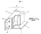
以下、発明の実施例を図面を用いて説明する。図1は本発明の特徴を最もよく表しているアンテナユニット11の一部断面斜視図である。図1において電波を送受信する部分の送受信アンテナ1は、送受信アンテナ1を固定するためのケーシング2の中に収められており、更に送受信アンテナ1を石はねや雨等から保護するためのレドーム3(カバー)が送受信アンテナ1の前面に取り付けられている。また、アンテナユニット11は金属ブラケット16により車両に設置されるが、金属ブラケット16の下部には、アンテナユニット11の前面から突出するような遮蔽部材4を設ける。
(動作の説明)
一般にアンテナユニットは車両前面に設置され、走行方向に存在するターゲットを検知するのに用いられる。そして、例えばミリ波レーダの一方式であるドップラレーダ方式においては、電波のメインビームをターゲットに向かって送信し、ターゲットで反射した電波のドップラ周波数及び送受信電波の位相差を観測することにより、ターゲットまでの速度と距離を求めることができる。しかし、その送信電波にはサイドローブが存在し、サイドローブの道路面からの強い反射波(グランドクラッタ)もターゲット信号と共に受信アンテナに入ってくる。
Hereinafter, embodiments of the present invention will be described with reference to the drawings. FIG. 1 is a partial cross-sectional perspective view of an
(Description of operation)
Generally, an antenna unit is installed on the front of a vehicle and is used for detecting a target existing in a traveling direction. For example, in a Doppler radar system, which is a type of millimeter wave radar, a target beam is transmitted by transmitting a main beam of radio waves toward a target and observing the Doppler frequency of the radio wave reflected by the target and the phase difference between transmitted and received radio waves. Speed and distance to can be obtained. However, the transmitted radio waves have side lobes, and strong reflected waves (ground clutter) of the side lobes from the road surface also enter the receiving antenna together with the target signal.
図12は、上記実施例において、グランドクラッタを引き起こすサイドローブ6と、メインビーム5の様子を模式的に表わしたものである。ここで、電波はアンテナユニット
11の1点から送信されているとする。また、水平面を基準として電波の放出角度を路面方向を正にθとする。始めに、サイドローブ6を遮断する遮蔽部材4を取り付けない状態における、受信信号のスペクトルを図13に示す。この例では、アンテナユニット11が電波送信方向に時速60[km/h]で移動しているので、路面に対するドップラ周波数が発生する。図13において6.7kHz(時速60[km/h]に相当) 以下のドップラ周波数におけるA領域のノイズフロアは、ほとんどがグランドクラッタによるノイズであり、このノイズがS/N比を下げ、その結果レーダの検知能力を低下させる。次に、遮蔽部材4をアンテナユニット11からX[mm]突出するように取り付け、電波放出点と遮蔽部材4との距離をH[mm]とすると、式(1)により放射角度θ(0〜90度)以上のサイドローブ6を遮断することができる。
FIG. 12 schematically shows the state of the side lobe 6 causing the ground clutter and the state of the main beam 5 in the above embodiment. Here, it is assumed that the radio wave is transmitted from one point of the
X=H/tanθ …式(1)
例えば1例として、45度以上の放射角度θを持ったサイドローブ6を遮断するためには、H=43.1[mm]の時、X=43.1[mm]となる。また、放射角度θとドップラ周波数fd[Hz]の関係は式(2)で表わされ、θ=45度以上のサイドローブ6を遮断した結果、4.7[kHz] 以下のドップラ周波数に相当するグランドクラッタを抑えることができる。この時のグランドクラッタの受信信号スペクトルを図14に示す。図よりグランドクラッタによるノイズレベルは、アンテナユニット11の電子回路部で発生するノイズレベルにまで減ることが示され、グランドクラッタを遮蔽部材4によりほぼ除去することができる。
X = H / tan θ Expression (1)
For example, as an example, to block a side lobe 6 having a radiation angle θ of 45 degrees or more, when H = 43.1 [mm], X = 43.1 [mm]. The relationship between the radiation angle θ and the Doppler frequency fd [Hz] is expressed by equation (2). As a result of blocking the side lobe 6 at θ = 45 degrees or more, it corresponds to a Doppler frequency of 4.7 [kHz] or less. Ground clutter can be reduced. FIG. 14 shows the received signal spectrum of the ground clutter at this time. The figure shows that the noise level due to the ground clutter is reduced to the noise level generated in the electronic circuit section of the
fd=2×V×cosθ/λ …式(2)
ここで、Vはアンテナユニット11の移動速度(この例では60[km/h])であり、λは電波の波長(この例では5[mm])である。
fd = 2 × V × cos θ / λ Equation (2)
Here, V is the moving speed of the antenna unit 11 (60 [km / h] in this example), and λ is the wavelength of the radio wave (5 [mm] in this example).
更に図13において、グランドクラッタによるノイズはドップラ周波数が低くなるほど高くなっているが、これは、電波の放射角度θが大きくなるにしたがってアンテナユニットと路面の距離が短くなり、グランドクラッタノイズの受信強度が上昇するためである。つまり、式(2)からfdが小さくなるにつれてθが大きくなり、その結果、アンテナユニットと路面の距離が短くなってグランドクラッタノイズが高くなるのである。そのため、サイドローブ6のうちθの大きな領域だけでも遮断する事により、グランドクラッタのノイズフロアを大きく下げることができる。 Further, in FIG. 13, the noise due to the ground clutter increases as the Doppler frequency decreases. This is because the distance between the antenna unit and the road surface decreases as the radiation angle θ of the radio wave increases, and the reception intensity of the ground clutter noise increases. Is to rise. That is, from equation (2), as fd decreases, θ increases, and as a result, the distance between the antenna unit and the road surface decreases, and ground clutter noise increases. Therefore, the noise floor of the ground clutter can be greatly reduced by blocking only the region of the side lobe 6 where θ is large.
以上より本発明によれば、アンテナユニット11のサイズ増加を最小限に抑えながら、安価で容易にグランドクラッタによるノイズを低減し、ターゲットの検知能力を向上することができる。
As described above, according to the present invention, it is possible to easily and inexpensively reduce noise caused by ground clutter and improve the target detection capability while minimizing the increase in the size of the
また、図3に示すように、遮蔽部材4はアンテナユニット11に直接取り付けても良い。
Further, as shown in FIG. 3, the
その他、遮蔽部材4の電波反射表面部に電波吸収材を貼付けすることにより、遮蔽部材4によるサイドローブ6の反射波の強度も低減することができる。
(その他の実施例)
図4は請求項2の実施の形態を示す概略図である。図のように遮蔽部材4としてケーシング2の一部を利用しても良い。
In addition, by attaching a radio wave absorbing material to the radio wave reflecting surface of the
(Other Examples)
FIG. 4 is a schematic view showing an embodiment of the present invention. As shown, a part of the
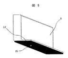
図5は請求項3の実施の形態を示す概略図である。図のように、レドーム3の前方下部に突出物17を形成し、その表面に金属メッキ15処理を行うことで、遮蔽部材4と同等の効果が生じる。また、金属メッキ15処理の代わりに電波吸収材を貼付けしたり、金属メッキ処理と電波吸収材の両方を用いても良い。
FIG. 5 is a schematic diagram showing the third embodiment. As shown in the figure, an effect equivalent to that of the
図6は請求項4の実施の形態を示す概略図である。例えば車両19の一部として、図のようにアンテナユニット11をボンネット20の上に置くことで、ボンネット20等車両19の一部を遮蔽部材4の代わりとしても良い。
FIG. 6 is a schematic view showing an embodiment of the fourth aspect. For example, as shown in the figure, the
図7は請求項5の実施の形態を示す概略図である。例えば車両の内部として、図のように遮蔽部材4の付いたアンテナユニット11をバンパ23内部等に設置しても良い。
FIG. 7 is a schematic diagram showing the fifth embodiment. For example, as shown in the figure, the
図8は請求項6の実施の形態を示す概略図である。図において7は融雪のためのヒータであり、遮蔽部材4を温めるために貼り付けられている。
FIG. 8 is a schematic diagram showing the sixth embodiment. In the figure,
図9は請求項7の実施の形態を示す概略図である。図のように、遮蔽部材4上に塵や埃,雪を落とすためのスリット9を設ける。更に、塵や埃,雪をスリット9より排除するのを助長するための空気を集める付属構造物8を取り付けたり、レドーム3の表面の形状を傾斜させることで、レドーム3表面に空気の流れを発生させる構造としてもよい。
FIG. 9 is a schematic diagram showing an embodiment of
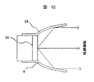
図10は請求項8の実施の形態を示す概略図である。図においてアンテナユニット11に、金属製でパラボラ形状の遮蔽部材4または付属構造物10が取り付けられており、側方に向かって放出される電波を前方向に反射させてもよい。
(実施の効果)
本発明の実施例においては、図1のように送受信アンテナ1の前方下部方向にサイドローブ6を遮断・減衰することのできる遮蔽部材4を金属ブラケット16に設置したので、従来のアンテナユニット11を用いながら、安価で容易にサイドローブによるグランドクラッタの影響を減少させることができる。
FIG. 10 is a schematic view showing an embodiment of the present invention. In the figure, a metallic
(Effects of implementation)
In the embodiment of the present invention, the shielding
また、請求項2の実施例図4のように遮蔽部材4とケーシング2を一体成型することにより、遮蔽部材4のアンテナユニット11への取り付手間を低減できる。
Further, by integrally molding the shielding
また、請求項3の実施例図5のようにレドーム3の前方下部に突出物17を設け、その表面に金属メッキ処理もしくは電波吸収材の貼付けを施すことにより、遮蔽部材4を用いた場合と同様の効果を得ることができる。さらにその突出物17はレドーム3と一体成形されていることから、安価に製作でき、重量も軽くできる。
Further, as shown in FIG. 5, a
また、請求項4の実施例図6のようにアンテナユニット11をボンネット20等車両
19の一部の上に置くことで、ボンネット20等車両19の一部を利用してサイドローブ6を遮断することができる。
Further, the
また、請求項5の実施例図7のように遮蔽部材4の付いたアンテナユニット11をバンパ23等車両の内部に設置することにより、雪がアンテナユニット11や遮蔽部材4に付着するのを軽減でき、更にアンテナユニット11の外部への接触による破損の危険性も減少することができる。
Further, by installing the
また、請求項6の実施例図8のように遮蔽部材4をヒータ7で温めることにより、その熱でレドーム3や遮蔽部材4に付着した雪を溶かし、雪の付着によるレーダの検知能力低下を防止する。併せて、ケーシング2の内部で発生した熱は遮蔽部材4に伝えることにより、融雪に利用できる。
In addition, as shown in FIG. 8, the
また、請求項7の実施例図9のように遮蔽部材4にスリット9を設けることにより、遮蔽部材4に付着する塵や埃,雪をそのスリット9より排除して、塵や埃,雪による検知性能劣化を低減する。また、空気を集める付属構造物8を設置することによりレドーム3表面に空気の流れを発生させ、塵や埃,雪をスリット9より排除する力として利用する。
Further, by providing the slit 9 in the shielding
また、請求項8の実施例図10のようにアンテナユニット11の前面にパラボラ形状の遮蔽部材4または付属構造物10を設置することにより、グランドクラッタを抑えたり、サイドローブをメインビームと同一方向に反射させて電波の指向性を高める事により検知性能が向上する。
Further, by installing the
1…送受信アンテナ、2…ケーシング、3…レドーム、4…遮蔽部材、5…メインビーム、6…サイドローブ、7…ヒータ、8…付属構造物、9…スリット、10…パラボラ形状の付属構造物、11…アンテナユニット、12…制御回路、13…表示器、14…接着剤、15…金属メッキ、16…金属ブラケット、17…突出物、18…ねじ、19…車両、20…ボンネット、21…車体フレーム、22…雪、23…バンパ、24…金属板。
DESCRIPTION OF
Claims (8)
前記送受信アンテナを収納するケーシングと、
前記送受信アンテナを保護するためのレドームとを備え、前記送受信アンテナのサイドローブによるグランドクラッタを遮断する遮蔽部材が前記レドームの外側で前記送受信アンテナ前方下部に突出するように設けられていることを特徴とするミリ波レーダ。 Transmitting and receiving antennas,
A casing for housing the transmitting and receiving antenna,
A radome for protecting the transmission / reception antenna, wherein a shielding member for blocking ground clutter due to side lobes of the transmission / reception antenna is provided so as to protrude to the front lower part of the transmission / reception antenna outside the radome. Millimeter wave radar.
前記レドーム表面の一部に金属メッキ処理または電波吸収材の貼付けを行うことを特徴とするミリ波レーダ。 2. The millimeter wave radar according to claim 1, wherein a metal plating process or a radio wave absorbing material is applied to a part of the radome surface instead of the shielding member.
前記遮蔽部材を代えて、搭載される車両の一部を遮蔽部材として利用することを特徴とするミリ波レーダ。 In claim 1,
A millimeter-wave radar, wherein a part of a mounted vehicle is used as a shielding member instead of the shielding member.
前記遮蔽部材を温めるための手段を設けることを特徴とするミリ波レーダ。 In claim 1,
A millimeter-wave radar, comprising means for warming the shielding member.
前記遮蔽部材にスリットを設けることを特徴とするミリ波レーダ。 In claim 1,
A millimeter wave radar, wherein a slit is provided in the shielding member.
前記送受信アンテナを収納するケーシングと、
前記送受信アンテナを保護するためのレドームとを備え、サイドローブをメインビームの送信方向と同一になるように反射させる形状を持った遮蔽部材が、レドームの外側で送受信アンテナ前方下部方向に設置されていることを特徴とするミリ波レーダ。
Transmitting and receiving antennas,
A casing for housing the transmitting and receiving antenna,
With a radome for protecting the transmitting and receiving antenna, a shielding member having a shape for reflecting the side lobe so as to be the same as the transmitting direction of the main beam is installed outside the radome in a lower front direction of the transmitting and receiving antenna. Millimeter-wave radar.
Priority Applications (1)
| Application Number | Priority Date | Filing Date | Title |
|---|---|---|---|
| JP2004117026A JP2004258044A (en) | 2004-04-12 | 2004-04-12 | Millimeter wave radar |
Applications Claiming Priority (1)
| Application Number | Priority Date | Filing Date | Title |
|---|---|---|---|
| JP2004117026A JP2004258044A (en) | 2004-04-12 | 2004-04-12 | Millimeter wave radar |
Related Parent Applications (1)
| Application Number | Title | Priority Date | Filing Date |
|---|---|---|---|
| JP2000014023A Division JP2001201557A (en) | 2000-01-19 | 2000-01-19 | Millimeter wave radar |
Publications (1)
| Publication Number | Publication Date |
|---|---|
| JP2004258044A true JP2004258044A (en) | 2004-09-16 |
Family
ID=33128490
Family Applications (1)
| Application Number | Title | Priority Date | Filing Date |
|---|---|---|---|
| JP2004117026A Pending JP2004258044A (en) | 2004-04-12 | 2004-04-12 | Millimeter wave radar |
Country Status (1)
| Country | Link |
|---|---|
| JP (1) | JP2004258044A (en) |
Cited By (13)
| Publication number | Priority date | Publication date | Assignee | Title |
|---|---|---|---|---|
| JP2007101390A (en) * | 2005-10-05 | 2007-04-19 | Matsushita Electric Ind Co Ltd | Transmission and reception integrated antenna system radar |
| JP2007232407A (en) * | 2006-02-27 | 2007-09-13 | Toyota Motor Corp | Apparatus for controlling directivity of radio beam and radio type vehicle intrusion detection apparatus |
| WO2012144150A1 (en) * | 2011-04-19 | 2012-10-26 | マツダ株式会社 | Obstacle detection device for vehicle |
| FR3014404A1 (en) * | 2013-12-10 | 2015-06-12 | Peugeot Citroen Automobiles Sa | CARRIER FOR DISTANCE DETECTION RADAR ON MOTOR VEHICLE |
| JP2015212705A (en) * | 2015-07-07 | 2015-11-26 | マツダ株式会社 | Obstacle detection device for vehicle |
| JP2016206034A (en) * | 2015-04-23 | 2016-12-08 | トヨタ自動車株式会社 | Radar device |
| JP2018085601A (en) * | 2016-11-22 | 2018-05-31 | 日本無線株式会社 | Flare for radar antenna and radar antenna |
| JP2018085602A (en) * | 2016-11-22 | 2018-05-31 | 日本無線株式会社 | Radar antenna |
| JP2019041342A (en) * | 2017-08-29 | 2019-03-14 | 三菱電線工業株式会社 | Tool unit and radio wave absorption box used therefor |
| KR20190052568A (en) * | 2017-11-08 | 2019-05-16 | 한국철도기술연구원 | Radar for vehicle |
| US10340588B2 (en) | 2014-10-16 | 2019-07-02 | Murata Manufacturing Co., Ltd. | Antenna module accommodation structure |
| WO2020209306A1 (en) * | 2019-04-08 | 2020-10-15 | 株式会社デンソー | Radar device and bracket for radar device |
| EP3574550A4 (en) * | 2016-07-12 | 2020-11-25 | PSA Automobiles SA | Mounting of antenna electronic boxes on a tail lid of a vehicle |
-
2004
- 2004-04-12 JP JP2004117026A patent/JP2004258044A/en active Pending
Cited By (20)
| Publication number | Priority date | Publication date | Assignee | Title |
|---|---|---|---|---|
| JP2007101390A (en) * | 2005-10-05 | 2007-04-19 | Matsushita Electric Ind Co Ltd | Transmission and reception integrated antenna system radar |
| JP2007232407A (en) * | 2006-02-27 | 2007-09-13 | Toyota Motor Corp | Apparatus for controlling directivity of radio beam and radio type vehicle intrusion detection apparatus |
| US9618615B2 (en) | 2011-04-19 | 2017-04-11 | Mazda Motor Corporation | Obstacle detection device for vehicle |
| WO2012144150A1 (en) * | 2011-04-19 | 2012-10-26 | マツダ株式会社 | Obstacle detection device for vehicle |
| JPWO2012144150A1 (en) * | 2011-04-19 | 2014-07-28 | マツダ株式会社 | Obstacle detection device for vehicle |
| JP5696781B2 (en) * | 2011-04-19 | 2015-04-08 | マツダ株式会社 | Obstacle detection device for vehicle |
| FR3014404A1 (en) * | 2013-12-10 | 2015-06-12 | Peugeot Citroen Automobiles Sa | CARRIER FOR DISTANCE DETECTION RADAR ON MOTOR VEHICLE |
| US10587040B2 (en) | 2014-10-16 | 2020-03-10 | Murata Manufacturing Co., Ltd. | Antenna module accommodation structure |
| US10340588B2 (en) | 2014-10-16 | 2019-07-02 | Murata Manufacturing Co., Ltd. | Antenna module accommodation structure |
| JP2016206034A (en) * | 2015-04-23 | 2016-12-08 | トヨタ自動車株式会社 | Radar device |
| JP2015212705A (en) * | 2015-07-07 | 2015-11-26 | マツダ株式会社 | Obstacle detection device for vehicle |
| EP3574550A4 (en) * | 2016-07-12 | 2020-11-25 | PSA Automobiles SA | Mounting of antenna electronic boxes on a tail lid of a vehicle |
| JP2018085601A (en) * | 2016-11-22 | 2018-05-31 | 日本無線株式会社 | Flare for radar antenna and radar antenna |
| JP2018085602A (en) * | 2016-11-22 | 2018-05-31 | 日本無線株式会社 | Radar antenna |
| JP2019041342A (en) * | 2017-08-29 | 2019-03-14 | 三菱電線工業株式会社 | Tool unit and radio wave absorption box used therefor |
| KR20190052568A (en) * | 2017-11-08 | 2019-05-16 | 한국철도기술연구원 | Radar for vehicle |
| KR102034546B1 (en) * | 2017-11-08 | 2019-10-21 | 한국철도기술연구원 | Radar for vehicle |
| WO2020209306A1 (en) * | 2019-04-08 | 2020-10-15 | 株式会社デンソー | Radar device and bracket for radar device |
| JP2020173105A (en) * | 2019-04-08 | 2020-10-22 | 株式会社Soken | Radar apparatus and bracket for radar apparatus |
| JP7132167B2 (en) | 2019-04-08 | 2022-09-06 | 株式会社Soken | Radar device and bracket for radar device |
Similar Documents
| Publication | Publication Date | Title |
|---|---|---|
| JP2001201557A (en) | Millimeter wave radar | |
| JP6007449B2 (en) | Automotive radar system and method of use thereof | |
| US10012720B2 (en) | Low reflection radar bracket | |
| JP5742417B2 (en) | Obstacle detection device for vehicle | |
| JP2009300390A (en) | Waterproof structure for millimeter wave radar device | |
| JP2007074662A (en) | Millimeter wave radar system | |
| JP2004258044A (en) | Millimeter wave radar | |
| JP2007057483A (en) | Millimeter wave radar device | |
| US20140375490A1 (en) | Radar device for a motor vehicle, securing device for a radar apparatus and method for manufacturing an absorption element for a radar apparatus | |
| JP2003240838A (en) | Periphery monitoring device for vehicle | |
| JP2012505115A (en) | Integrated radar-camera sensor | |
| JP6317657B2 (en) | Radar sensor module | |
| JP2004101450A (en) | Structure for mounting electric wave radar | |
| CN111196238B (en) | Sensor mounting structure | |
| JP2004531726A (en) | Sensor system for determining the surrounding environment of a car | |
| KR101734334B1 (en) | Road monitoring radar device | |
| JP2005142913A (en) | In-vehicle lens antenna | |
| JP2002347520A (en) | Vehicle periphery surveillance device | |
| US6433750B1 (en) | Reception antenna for radio wave marker | |
| JP2005257352A (en) | Wrong detection prevention structure for sensor, and sensor | |
| JP5453944B2 (en) | Object detection unit mounting structure | |
| JPH06168400A (en) | Radar for automobile | |
| JP2008074352A (en) | Front grille | |
| WO2022044914A1 (en) | Vehicular radar system and vehicle | |
| EP4024611A1 (en) | Radar device |
Legal Events
| Date | Code | Title | Description |
|---|---|---|---|
| RD01 | Notification of change of attorney |
Free format text: JAPANESE INTERMEDIATE CODE: A7421 Effective date: 20060421 |
|
| A621 | Written request for application examination |
Free format text: JAPANESE INTERMEDIATE CODE: A621 Effective date: 20061004 |
|
| A131 | Notification of reasons for refusal |
Free format text: JAPANESE INTERMEDIATE CODE: A131 Effective date: 20090616 |
|
| A521 | Written amendment |
Free format text: JAPANESE INTERMEDIATE CODE: A523 Effective date: 20090810 |
|
| A02 | Decision of refusal |
Free format text: JAPANESE INTERMEDIATE CODE: A02 Effective date: 20091110 |
|
| A711 | Notification of change in applicant |
Free format text: JAPANESE INTERMEDIATE CODE: A712 Effective date: 20091221 |