【0001】
【発明の属する技術分野】
本発明は、種々の表示を行うための半導体発光素子を有する電気機器において光による通信を行う技術、及び、電気機器に対して指示情報を送信するための技術に関するものである。
【0002】
【従来の技術】
従来より様々な電気機器において、LED(Light Emitting Diode)などの半導体発光素子が表示用として用いられている。図9,図10は、電気機器においてLEDを表示用として利用した形態の一例の説明図である。図9(A)はTVセットの例を示しており、電源の入切や表示時及び待機時の別、あるいは入力端子の別などを表示するためのLEDが設けられている。また図9(B)にはオーディオ機器の例を示しているが、やはりこの場合も、電源の入切を示すLEDが設けられている。さらに図9(C)に示した例は、計測器等に設けられているメータのそれぞれにLEDが設けられ、それぞれのメータの動作状態やメータが示している値の状態などを表示している。
【0003】
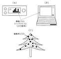
このような単なる発光でユーザに表示内容を伝えるだけでなく、文字や絵などを表示するための表示手段にもLEDなどの半導体発光素子が利用されている。例えば図10(A)には、液晶パネルが設けられた機器の例を示している。このような液晶パネルでは、バックライトとしてLEDが広く利用されている。同様に図10(B)にはノートパソコンの例を示しているが、この場合も表示手段として多くの場合、バックライト付きの液晶パネルを利用している。この場合のバックライトとしても、LEDが利用されている。また、多数のLEDを配列した電光掲示板などの表示手段も開発され、利用されている。
【0004】
さらに上述のような発光を視認することによってユーザが情報を得るような用途の他にも、例えば装飾用にも広くLEDなどの半導体発光素子が利用されるようになってきている。図10(C)に示す例では、クリスマスツリーの電飾に利用した例を示している。また同様に、店の看板やインテリアなどの装飾に利用されている。このほかにも、様々な電気機器にLEDなどの半導体発光素子が利用されている。
【0005】
このような電気機器に設けられているLEDなどの半導体発光素子は、人間に対して光を直接視認させ、情報の伝達や美的感覚を引き起こすものである。従来はその用途のみに用いられることはあっても、他の用途に用いられることはなかった。
【0006】
一方、LEDなどの半導体発光素子は、白熱電球や蛍光灯などの従来の照明光源と比較し、長寿命、小型、低消費電力であるといった特徴があり、このような特徴を利用して上述のような各種の用途において利用されている。さらにLEDなどの半導体発光素子は、上述のような特徴に加え、余熱時間が不要なため応答速度が非常に速いという特性を持つ。この速い応答速度、及び電気的に制御できることに着目し、例えば非特許文献1などに記載されているように、LEDを用いて照明器具を構成し、照明光に信号を重畳して照射することによって、照明光に信号伝送機能を持たせる研究が現在行われている。しかし、照明器具としてLEDを利用したものはほとんどなく、既にLEDなどの半導体発光素子が利用されている分野への応用が期待されている。
【0007】
【非特許文献1】
小峯 敏彦,田中 裕一,中川 正雄,「白色LED照明信号伝送と電力線信号伝送の融合システム」,電子情報通信学会技術研究報告,社団法人電子情報通信学会,2002年3月12日,Vol.101,No.726,pp.99−104
【0008】
【発明が解決しようとする課題】
本発明は、上述した事情に鑑みてなされたもので、人間に対して光を直接視認させるための表示手段に用いられているLEDなどの半導体発光素子を、装置間の通信に利用することを目的とするものである。
【0009】
【課題を解決するための手段】
本発明は、表示用の半導体発光素子を有する電気機器において、情報に従って前記半導体発光素子の点滅あるいは発光量を制御する制御手段を有し、表示用の前記半導体発光素子を用いて情報を送信することを特徴とするものである。例えば、装置の状態を表示するためのLED光源や、表示手段の照明用のLED光源等は、それぞれの表示目的によって従来より設けられており、この半導体発光素子を機器間の通信に利用することによって、新たな通信手段を設けずに情報の伝送を行うことが可能となる。また、装飾のためのLED光源を有しているものにおいても、その装飾という本来の機能に情報の伝送という新たな機能を持たせることができる。また、外観上も部品が増加することはなく、従来と同様のデザインを損なうことがない。
【0010】
表示用の半導体発光素子を用いた情報伝送は、本機から他の機器への情報の送信が可能であるが、情報を受信するための構成としては、例えばTVセットやビデオデッキなどで広く利用されている赤外線を用いた受信手段をそのまま利用することができる。あるいは、外部からの光を受光する受光手段を設け、他の装置から光を変調することによって送られてくる情報を受信するように構成し、送受信とも光による通信を行うことができる。
【0011】
また本発明は、上述の赤外線を用いた受信手段を有する電気機器に対して指示を行うためのコントローラにおいて、電気機器からの送信情報により変調され発光された光を受光して送信情報を受信する受光手段と、電気機器に対して指示情報を送信するための赤外光通信手段を有することを特徴とするものである。このような構成によって、上述のように電気機器に設けられた表示用の半導体発光素子で発光した光により情報を受け取り、また赤外線により電気機器に対して情報を送信して、電気機器に対する指示を行うことができる。
【0012】
さらに本発明は、上述の受光手段を有する電気機器に対して指示を行うためのコントローラにおいて、半導体発光素子と、前記電気機器に対して送信する指示情報に従って前記半導体発光素子の点滅あるいは光量を制御する変調手段を有することを特徴とするものである。特に、半導体発光素子から放出される光を集光するための光学系を設けておくと、情報を伝送するための光がスポット光として電気機器に届くことになる。あたかも懐中電灯をかざすがごとく、情報を送信したい電気機器に対してスポット光を向けることができ、確実に、しかも選択的に、電気機器に対して光により情報を送信することが可能となる。
【0013】
なお、この場合、電気機器からの発光され送信情報により変調された光を受光して前記送信情報を受信する受光手段を設けておくことによって、送受信とも光による通信が可能となる。
【0014】
また、受光手段を設けたコントローラの構成において、受光手段に集光するための光学系を設けておくことができる。このような構成によって、外部の発光源が複数存在する場合でも、光学系によって発光源を選択することができ、送信情報を選択的に受信可能とすることができる。
【0015】
【発明の実施の形態】
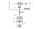
図1は、本発明の電気機器の実施の一形態を示すブロック図である。図中、1は電気機器、2は受信機、11はLED、12は制御部、21は受光部、22は光学系、23は復調部である。ここでは半導体発光素子の一例としてLED11が用いられた例を示している。このほかにもレーザダイオードやEL素子やプラズマ表示素子など、他の半導体発光素子でも同様である。
【0016】
LED11は、電気機器に従来より設けられている表示のためのLED光源であり、ここでは例えば電源等の装置の状態を表示するためのものである。なお、LED11は、単一の素子で構成されることもあるし、複数の素子で構成されることもある。また、単一の素子内に複数色の発光領域を有するなど、素子構成も種々のものがある。
【0017】
制御部12は、情報に従ってLED11の点滅あるいは発光量を制御し、LED11の発光光を変調して情報を送信する。LED11は、上述のように応答速度が非常に速いという性質を有しており、情報に従って高速に点滅あるいは発光量を制御することによって情報を送信することができる。また、高速な点滅あるいは発光量の制御を行っても、そのような点滅や発行量の変化は人間には視認できず、あたかも連続点灯しているかのように視認される。従って、従来のLED11の点灯状態を保ったまま、情報の送信を行うことができる。なお、変調方式は任意であり、種々のデジタルまたはアナログの変調方式を適用することができる。
【0018】
このような構成によって、従来から電気機器に表示用として設けられているLED11を利用して、その表示機能を保ったまま、情報の送信を行うことができる。電気機器は、多くの機能を要求されるのものの、限られた面積に、かつシンプルなデザインの中に機能を増加させる必要がある。そのため、従来から設けられているLED11を利用することによって、装置を大型化することなく、情報の送信機能を追加することが可能となる。
【0019】
受信機2は、電気機器1のLED11が発光した、変調された光を受光し、情報を受信する。そのための構成として、光を受け取って電気信号に変換する受光部21と、電気信号を復調して情報を取り出す復調部23を含んで構成されている。上述の電気機器1からの光は受光部21で受光され、復調部23で情報が取り出されることによって、電気機器1から受信機2への情報の伝送が実現する。
【0020】
また受光部21にレンズなどの光学系22を設けることができる。この光学系22を設けることによって、受光する光の光源を限定することが可能となり、ピンポイントで情報を受信することができる。そのため、類似の電気機器が並んでいる場合でも、他の電気機器からの情報伝送の干渉を受けることなく、特定の電気機器からの情報を受信することができる。
【0021】
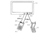
図2は、本発明の電気機器の実施の一形態における第1の応用例を示す概略図である。図中、31はTVセット、32はLED、33は赤外線受光部、41はリモコン、42は受光部、43は赤外光送信部、44は表示部、51は携帯端末、52はカメラである。図2に示す例では、本発明をTVセットに適用した例を示している。
【0022】
TVセット31では、従来よりリモコン41による遠隔操作が可能である。リモコン41からTVセット31への通信は、赤外線を用いるのが一般的である。図2に示す例では、そのための構成として、リモコン41に赤外光送信部43が設けられ、またTVセット31側に赤外線受光部33が設けられている。このような構成によって、リモコン41においてユーザが操作を行うと、その操作に対応する情報がTVセット31に赤外線によって送信される。例えばチャンネルの選択操作をリモコン41で行うと、選択されたチャンネルの情報が赤外光送信部43から赤外線によってTVセット31に送られ、TVセット31の赤外線受光部33で受信されて、選択されたチャンネルに切り替える。なお、一般のTVセット31では、リモコン41からTVセット31への片方向の通信しか行っていない。
【0023】
TVセット31には、通常、電源の入切や、表示状態か待機状態かを表示するための1ないし複数のLED32が設けられている。本発明では、このLED32を図1に示すLED11として用い、情報の送信を行う。すなわち、LED32は、従来から行われている電源の入切や状態表示などの機能とともに、情報に応じた変調駆動がなされ、可視の変調光を放出して情報を送信する機能を持つ。
【0024】
リモコン41には、TVセット31から放出される変調光を受光するための受光部42が設けられている。この受光部42によってTVセット31から放出される可視の変調光を受光し、内部で復調することによってTVセット31から送られてくる情報を受信することができる。
【0025】
これによって、TVセット31からリモコン41への情報転送を実現することができる。従来は片方向の通信であったTVセット31とリモコン41との間の通信は、両方向の通信が可能となり、TVセット31の状態をリモコン41側で受信し、ユーザに伝達することができるようになる。これを利用し、例えばTVセット31の取り扱い方法や番組予約状態などをTVセット31からリモコン41へ送信し、リモコン41側で受信して表示部44に表示し、確認することが可能となる。またTVセット31の状態をリモコン41の表示部44で確認しながら、各種の操作を行うことも可能となる。
【0026】
図2では、さらにカメラ52が設けられた携帯端末51の例を示している。TVセット31のLED32を用いて送信される情報は、リモコン41などのような専用の装置でなくても、可視光が受光可能な各種の装置において情報の受信が可能である。近年、カメラ付きの携帯電話やPDAが盛んに利用されてきており、これらを携帯端末51として利用し、TVセット31から送られてくる情報を受信することができる。また、例えばデジタルカメラやデジタルビデオなどのように、もともと撮像機能を有している機器に通信機能を持たせることも可能である。
【0027】
リモコン41及び携帯端末51のいずれにおいても同様であるが、例えばTVセット31で受信している番組内容をTVセット31から送信し、携帯端末51の表示部に表示し、またスピーカから音声再生することができる。例えばTVセット31と異なる番組(裏番組)を表示させて調べたり、例えば文字放送などをTVセット31の画面に表示せずにリモコン41及び携帯端末51側で表示し、見ることができる。
【0028】
このような可視光を用いた情報の伝送は、LED32が点灯している状態であれば可能であるため、例えば視聴していない待機状態の場合でも通信が可能である。また、リモコン41の受光部42にレンズなどの光学系を設けた場合や携帯端末51のカメラ52などでは、光源からの光を選択的に受光することができるため、例えばTVセットが複数台並置されている場合でも、特定のTVセットからの情報を選択的に受信することが可能である。
【0029】
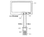
図3は、本発明の電気機器の実施の一形態における第1の応用例の変形例を示す概略図である。図中、図2と同様の部分には同じ符号を付して重複する説明を省略する。34は受光部、45は発光部である。図2に示した例では、リモコン41からTVセット31への情報伝送は赤外線によって行ったが、図3に示す変形例では、リモコン41からTVセット31への情報伝送についても可視光によって行う例を示している。なお、TVセット31からリモコン41への可視光による情報伝送については上述の例と同様である。
【0030】
リモコン41からTVセット31への可視光による情報伝送を実現するため、リモコン41側には発光部45が設けられるとともに、TVセット31側には受光部34が設けられている。これらは図2に示した赤外光送信部43及び赤外線受光部33に対応するものである。
【0031】
リモコン41側から情報を送信する場合には、発光部45を情報に応じて変調した信号によって発光させればよい。変調された光は、TVセット31側の受光部34において受光され、復調することによってリモコン41から送られてきた情報を受信することができる。
【0032】
リモコン41に設けられた発光部45には、ミラーやレンズなどの光学系を設け、発光部45から放出される変調光のビームを絞るように構成するとよい。これによって、TVセット31に対して効率よく変調された光を届けることが可能である。それとともに、この通信で利用している光は可視光であるため、絞られた光ビームがTVセット31に届くと、例えば懐中電灯などと同様に、図3に示すようにTVセット31の面を明るく照明する。これによって、リモコン41から放出された光によって照射されている領域を視認することができる。例えば複数台のTVセット31が存在する場合でも、情報の送信先となるTVセットを確実に特定し、確認して、情報を送信することができる。
【0033】
赤外光では目に見えないため、情報の送信先を特定できないし、また複数台のTVセットが存在する場合、コントローラ側でIDなどを変更する設定操作が必要であった。しかし、本発明ではそのような設定は不要であり、操作したいTVセットに光が照射されていることを目で確認し、リモコン操作を行えばよく、確実な操作を簡単に行うことができる。
【0034】
なお、リモコン41はTVセットに限らず、例えばビデオやDVD、オーディオ機器、エアコン、その他様々な機器においても利用されており、それらの機器において上述の第1の応用例は同様にして適用可能である。
【0035】
さらに、LEDなどの半導体発光素子によって電源状態や機器状態を表示する機能が存在するあらゆる機器において本願発明を適用可能であり、次に測定装置などに応用した例を示す。図4は、本発明の電気機器の実施の一形態における第2の応用例を示す概略図である。図中、61は計器、62はLED表示器である。なお、携帯端末51は図2に示したものと同様であり、カメラ52が設けられたものである。
【0036】
図4に示すように、飛行機のコックピット、工場などの制御盤等には、様々な計器61が並べられている。それとともに、それぞれの計器61には、その計器61に対応する機器が動作しているか否かやその状態等がLED表示器62によって表示されている場合が多い。このLED表示器62を図1に示すLED11として用い、情報の送信を行う。すなわち、LED表示器62は、従来から行われている機器の動作状態などを表示する機能とともに、情報に応じた変調駆動がなされ、可視の変調光を放出して情報を送信する機能を持つ。例えば、それぞれの計器61が担当する装置の状態や、計器61が示している値、計器61が設けられている測定装置や制御装置のマニュアルなど、様々な情報を送信することができる。
【0037】
このようにして計器61に設けられているLED表示器62から放出された変調光は、例えばカメラ52が設けられた携帯端末51などにおいて受信することが可能である。特に図4に示すように計器61が多数設置されている場合に、カメラ52によって選択的に計器61のLED表示器62を撮像することによって、特定の計器61のLED表示器62からの情報を受信することができる。例えば左から4番目の計器61の詳細な状態やマニュアルを知りたい場合には、4番目の計器61のLED表示器62のみを撮像すればよい。これによって、左から4番目の計器61のLED表示器62から送信される情報のみを選択的に受信することができる。このとき、カメラ52で撮像される映像をユーザが見ながらLED表示器62の位置を捕捉すれば、間違えることなく確実に所望の情報を取得することができる。
【0038】
もしもこのような情報を電波などで通信を行うとすれば、電波は周囲に広がるので、ピンポイントに捕捉できず、他の計器の情報を受信してしまうこともある。または、周波数、時間、コードなどを異ならせて送信する必要があり、受信側で特定の計器からの電波を選択するなど、面倒な操作及び確認をしなければならない。こうした狭い場所に複数の装置があり、その中から、一つを間違いなく直接選び出すことができるのは、可視光を用いた通信の利点である。
【0039】
上述のような計器61との通信を順次行ってゆくことによって、携帯端末51には計器61からの情報が蓄積されることになる。この蓄積された情報を携帯端末51あるいは他の端末やホストに転送し、処理を行うことが可能である。例えば電力メータや水道、ガスメータなどにおける検針に応用することも可能である。
【0040】
図5は、本発明の電気機器の実施の一形態における第2の応用例の変形例を示す概略図である。図中、53は発光部、63は受光部である。上述の図2,図3に示した例と同様に、計器61についても可視光あるいは赤外光を受光する受光部63を設け、また携帯端末51に可視光あるいは赤外光を発光する発光部53を設け、携帯端末51から計器61への通信も可能として双方向通信を行うように構成することもできる。このように双方向通信を可能とすることによって、例えば携帯端末51から計器61に対して、計器61の確認や情報の転送要求を行ったり、あるいは情報転送後の確認を計器61に返すなど、確実な通信が可能となる。
【0041】
また、このような計器61と携帯端末51との間でのハンドシェイクが行われた場合、例えば計器61のLED表示器62をユーザが見える程度の点滅や色の変更などを行うことによって、同じLED表示器62で通信可能あるいは通信中などの状態も表示することが可能である。これによって、ユーザにとっても他の計器と見間違うことなく、確実に通信対象の計器61を選択し、通信を行うことができる。
【0042】
なお、図3でも説明したように、携帯端末51側の発光部53に光学系を設けておき、光のビームを絞ることによって、特定の計器61へのピンポイントの情報伝送が可能となるまた、どの計器61へ情報を送っているかは、計器61に照射されたスポット光により判断することができ、視覚的に確認することができる。
【0043】
上述のように、本発明は家電製品だけでなく、計測器や工場の制御盤等の産業用機器にも応用可能である。そのほか、広く事務機器、車や航空機などの輸送用機器など、様々な用途に適用可能である。
【0044】
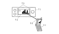
図6は、本発明の電気機器の実施の一形態における第3の応用例を示す概略図である。図中、71はオーディオ機器、72は液晶パネル、73はバックライト用LEDである。上述の第1,第2の応用例では、LED単独で装置の電源状況や装置状態などをLEDにより表示する例を示したが、本発明はこれに限られるものではない。この第3の応用例では、表示装置に組み込まれているLED等の半導体発光素子を通信に利用する例を示している。なお、携帯端末51は図2や図4、図5に示したものと同様であり、少なくともカメラ52が設けられたものである。
【0045】
ここではオーディオ機器71を具体例として示している。最近のオーディオ機器71には、各種の情報を表示するために液晶パネル72が設けられている。この液晶パネル72にはバックライトとしてLEDが多く利用されている。このバックライト用LED73を図1に示すLED11として用い、情報の送信を行う。すなわち、液晶パネル72には情報が表示されており、ユーザは液晶パネル72に映し出された画像を参照することができるが、これとは別にバックライト用LED73を送信する情報に従って変調駆動することによって、バックライトの光を用いて情報を送信することができる。バックライトの光を例えば携帯端末51等において受光し、復調することによって情報を受信することができる。
【0046】
また、上述の第1の応用例及びその変形例や第2の応用例の変形例のように、双方向の通信を行う場合には、液晶パネル72のバックライト用LED73のそばや、液晶パネル72の液晶層の背面に受光素子あるいは受光層を設け、可視光又は赤外光を受光するように構成するとよい。バックライト用LED73の光が液晶層を透過する状態では、外部からの光も液晶層を通過することができるので、このように液晶パネル72の内部に受光部を設けた構成が可能となる。そして、携帯端末51に可視光あるいは赤外光の発光素子を設け、送信する情報により変調された可視光あるいは赤外光を発光し、液晶パネル72中の受光部により受光して復調すればよい。これによって、携帯端末51からオーディオ機器71への情報の伝送についても行うことができ、双方向の通信が可能となる。
【0047】
もちろん、オーディオ機器71がリモコンにより操作可能な機器であれば、上述の第1の応用例のようにリモコンを用いる場合についても、同様にしてバックライト用LED73を用いた可視光による通信を行うことができる。また、ここではオーディオ機器71を具体例として示したが、これに限らず、LEDを光源として用いた様々な表示装置を搭載した機器について応用することができる。例えば家電製品の表示部や、無線機、ノート型パソコン、液晶ディスプレイ、液晶テレビ、自動車等のインパネの液晶表示、カーナビなど、LEDをバックライトとして用いた液晶表示装置を利用しているあらゆる機器において利用可能である。また、上述の携帯端末などにおいても、表示部に照明用のLEDを利用して同様に通信を行うことが可能である。
【0048】
さらに、LED以外の半導体発光素子を光源として利用した様々な表示装置において適用可能であるし、液晶表示装置に限らず、応答特性の非常に高速な素子であれば他の方式の表示装置でも同様にして可視光による通信が可能である。
【0049】
図7は、本発明の電気機器の実施の一形態における第4の応用例を示す概略図である。図中、81はクリスマスツリー、82はイルミネーションランプ、83はLED、84は受光素子である。この第4の応用例では、装飾用としてLEDが利用されている場合について示しており、その一例としてクリスマスツリー81の場合を示している。なお、携帯端末51は図2や図4、図5、図6に示したものと同様であり、少なくともカメラ52が設けられたものである。
【0050】
クリスマスツリー81には様々な装飾が施されるが、その一つとしてイルミネーションランプ82が用いられる。イルミネーションランプ82は、電線上に適当な間隔で光源を配置したもので、これをクリスマスツリー81などに掛け、光源を点滅させることによって光による装飾を行うものである。
【0051】
近年、イルミネーションランプ82にもLED83を用いたものが開発されている。このLED83を図1に示すLED11として用い、情報の送信を行うことができる。すなわち、LED83の点灯時に、情報に応じて変調駆動することによって変調された可視光を発光させることができる。この変調光を例えば携帯端末51等において受光し、復調することによって情報を受信することができる。このようにして、例えば通行人などがクリスマスツリー81を見ている時に携帯端末51をかざせば、クリスマスツリー81から送られてくるメッセージや画像、音声などの種々の情報を受信することができる。
【0052】
また、イルミネーションランプ82にはLED83が配置されていない部分もたくさんあるので、この部分に可視光や赤外光を受光する受光素子84を設けておくことができる。そして、携帯端末51に可視光あるいは赤外光の発光素子を設け、送信する情報により変調された可視光あるいは赤外光を発光し、受光素子84により受光して復調すればよい。これによって、携帯端末51からクリスマスツリー81への情報の伝送についても行うことができ、双方向の通信が可能となる。もちろん、受光素子84はイルミネーションランプ82とは別に、他の装飾品とともにクリスマスツリー81に配置してもよい。
【0053】
この第4の応用例ではクリスマスツリーのイルミネーションランプの例を示したが、これ以外でも、各種の装飾用に利用されているLEDなどの半導体発光素子を可視光による通信に利用することができる。例えば電飾を施した衣装や、パレードなどで登場する山車のイルミネーション、インテリア家具などの装飾、店先や建物の電飾など、様々な装飾に利用されているLEDなどの半導体発光素子を可視光の通信に用いることができる。
【0054】
図8は、本発明の電気機器の実施の一形態における第5の応用例を示す概略図である。図中、91は電光掲示板である。近年、多数の光源を配置した電光掲示板91が広く利用されており、その光源としてLEDが多く利用されるようになってきた。また、電光掲示板91には、情報の表示を行う部分以外にも、装飾のためのLEDが配置される場合もある。これらの情報の表示を行うためのLEDや装飾のためのLEDなどを図1に示すLED11として用い、情報の送信を行うことができる。例えば通行人などが電光掲示板91にカメラ付きの携帯端末51等をかざせば、電光掲示板91から送られてくるメッセージや画像、音声などの種々の情報を受信することができる。
【0055】
もちろん、電光掲示板91に可視光や赤外光を受光する受光素子を設けておけば、可視光あるいは赤外光の発光素子が設けられた携帯端末51との間で双方向の通信を行うことが可能である。
【0056】
電光掲示板91は、街頭でニュースなどを表示するほか、店先で看板として利用されていたり、列車やバスなどの行先表示や種別表示、料金表示など、様々な用途における表示に利用されている。このような種々の用途に用いられている電光掲示板に大して本発明を適用可能である。そのほか、工事中の指示灯や誘導員が所持している誘導灯、路上や路面に設けられている標識灯など、半導体発光素子が用いられている種々の用途について、その半導体発光素子を通信用として用い、可視光による通信を行うことが可能である。
【0057】
【発明の効果】
以上の説明から明らかなように、本発明によれば、人間に対して光を直接視認させ、情報を伝達したり美的感覚を想起させるための表示手段に用いられているLEDなどの半導体発光素子を、表示手段としての機能をそのままに、情報に従って変調駆動することによって、可視光による通信に利用することができる。このように既存の半導体発光素子を利用することによって、新たに送信手段を設けることなく通信が可能となり、装置の大型化や意匠的な変更を行う必要が無くなる。
【0058】
また、従来よりリモコンを用いている電気機器では、そのリモコンに受光手段を搭載することによって、電気機器から送られてくる情報を受信することができる。リモコン以外でも、カメラ付きの携帯端末等でも情報の受信が可能である。この場合、カメラなどのように光学系を有し、受光ビームを絞ることができると、情報の発信源である光源を特定することができ、ピンポイントでの受信が可能となる。
【0059】
さらに、可視光や赤外線などの送信機能を有していれば、電気機器との間で双方向の通信が可能となる。なお、リモコン側に可視光による送信機能を有している場合には、送信に用いる光のビームによって送信先となるエリアが照明されることによって、送信先の機器を確実に視認して特定することができ、容易に情報の送信先を特定した通信が可能となるという効果がある。
【図面の簡単な説明】
【図1】本発明の電気機器の実施の一形態を示すブロック図である。
【図2】本発明の電気機器の実施の一形態における第1の応用例を示す概略図である。
【図3】本発明の電気機器の実施の一形態における第1の応用例の変形例を示す概略図である。
【図4】本発明の電気機器の実施の一形態における第2の応用例を示す概略図である。
【図5】本発明の電気機器の実施の一形態における第2の応用例の変形例を示す概略図である。
【図6】本発明の電気機器の実施の一形態における第3の応用例を示す概略図である。
【図7】本発明の電気機器の実施の一形態における第4の応用例を示す概略図である。
【図8】本発明の電気機器の実施の一形態における第5の応用例を示す概略図である。
【図9】電気機器においてLEDを表示用として利用した形態の一例の説明図である。
【図10】電気機器においてLEDを表示用として利用した形態の別の例の説明図である。
【符号の説明】
1…電気機器、2…受信機、11…LED、12…制御部、21…受光部、22…光学系、23…復調部、31…TVセット、32…LED、33…赤外線受光部、34…受光部、41…リモコン、42…受光部、43…赤外光送信部、44…表示部、45…発光部、51…携帯端末、52…カメラ、53…発光部、61…計器、62…LED表示器、63…受光部、71…オーディオ機器、72…液晶パネル、73…バックライト用LED、81…クリスマスツリー、82…イルミネーションランプ、83…LED、84…受光素子、91…電光掲示板。[0001]
TECHNICAL FIELD OF THE INVENTION
The present invention relates to a technology for performing communication by light in an electric device having a semiconductor light emitting element for performing various displays, and a technology for transmitting instruction information to the electric device.
[0002]
[Prior art]
2. Description of the Related Art Conventionally, in various electric appliances, a semiconductor light emitting element such as an LED (Light Emitting Diode) has been used for display. 9 and 10 are explanatory diagrams of an example of a mode in which an LED is used for display in an electric device. FIG. 9A shows an example of a TV set, which is provided with LEDs for displaying power on / off, display, standby, or an input terminal. FIG. 9B shows an example of an audio device. In this case, too, an LED for indicating power on / off is provided. Further, in the example shown in FIG. 9C, an LED is provided in each of the meters provided in the measuring instrument and the like, and the operation state of each meter, the state of the value indicated by the meter, and the like are displayed. .
[0003]
Semiconductor light-emitting elements such as LEDs are used not only to convey display contents to a user by such simple light emission but also as display means for displaying characters, pictures, and the like. For example, FIG. 10A illustrates an example of a device provided with a liquid crystal panel. In such a liquid crystal panel, an LED is widely used as a backlight. Similarly, FIG. 10B shows an example of a notebook personal computer. In this case, a liquid crystal panel with a backlight is often used as a display means. An LED is also used as a backlight in this case. In addition, display means such as an electric signboard in which a large number of LEDs are arranged has been developed and used.
[0004]
Furthermore, semiconductor light-emitting elements such as LEDs have come to be widely used, for example, for decoration purposes, in addition to applications in which a user obtains information by visually confirming light emission as described above. In the example shown in FIG. 10C, an example is shown in which a Christmas tree is illuminated. Similarly, it is used for decorating shop signs and interiors. In addition, semiconductor light emitting devices such as LEDs are used in various electric appliances.
[0005]
A semiconductor light emitting element such as an LED provided in such an electric device causes light to be directly visually recognized by a human, thereby causing information transmission and aesthetic sensation. Conventionally, it was used only for that purpose, but was not used for other purposes.
[0006]
On the other hand, semiconductor light-emitting elements such as LEDs have features such as longer life, smaller size, and lower power consumption compared to conventional illumination light sources such as incandescent lamps and fluorescent lamps. It is used in various applications. Further, a semiconductor light emitting element such as an LED has a characteristic that, in addition to the above-described features, the response speed is extremely fast because no extra heat time is required. Focusing on this fast response speed and the fact that it can be electrically controlled, for example, as described in Non-Patent Document 1, for example, a lighting fixture is configured using an LED, and a signal is superimposed on illumination light and irradiated. Research is currently being conducted to make illumination light have a signal transmission function. However, there are few lighting devices that use LEDs, and applications to fields in which semiconductor light-emitting elements such as LEDs are already used are expected.
[0007]
[Non-patent document 1]
Toshihiko Komine, Yuichi Tanaka, Masao Nakagawa, "A Fusion System of White LED Lighting Signal Transmission and Power Line Signal Transmission", IEICE Technical Report, IEICE, March 12, 2002, Vol. 101, no. 726 pp. 99-104
[0008]
[Problems to be solved by the invention]
The present invention has been made in view of the above-described circumstances, and it is an object of the present invention to use a semiconductor light emitting element such as an LED used as a display unit for allowing a person to visually recognize light directly for communication between devices. It is the purpose.
[0009]
[Means for Solving the Problems]
The present invention relates to an electric device having a semiconductor light emitting element for display, comprising control means for controlling blinking or the amount of light emission of the semiconductor light emitting element according to information, and transmitting information using the semiconductor light emitting element for display. It is characterized by the following. For example, an LED light source for displaying the state of the device, an LED light source for illuminating the display means, and the like are conventionally provided for respective display purposes, and this semiconductor light emitting element is used for communication between devices. Accordingly, it is possible to transmit information without providing a new communication unit. Further, even in a device having an LED light source for decoration, the original function of the decoration can be provided with a new function of transmitting information. Also, the number of components does not increase in appearance, and the same design as in the related art is not spoiled.
[0010]
In information transmission using a semiconductor light emitting element for display, information can be transmitted from this unit to other devices, but as a configuration for receiving information, it is widely used, for example, in TV sets and VCRs. It is possible to use the receiving means using infrared rays as it is. Alternatively, a light receiving means for receiving light from the outside may be provided to receive information transmitted by modulating light from another device, and light transmission and reception may be performed.
[0011]
According to the present invention, in a controller for giving an instruction to an electric device having the above-mentioned receiving means using infrared rays, the controller receives light emitted by being modulated by the transmission information from the electric device and receives the transmission information. It is characterized by having light receiving means and infrared light communication means for transmitting instruction information to an electric device. With such a configuration, information is received by light emitted from the semiconductor light emitting element for display provided in the electric device as described above, and information is transmitted to the electric device by infrared rays, and an instruction to the electric device is issued. It can be carried out.
[0012]
Further, the present invention provides a controller for issuing an instruction to an electric device having the above-described light receiving means, wherein the controller controls the semiconductor light emitting device and the blinking or light amount of the semiconductor light emitting device according to instruction information transmitted to the electric device It is characterized by having a modulating means. In particular, if an optical system for condensing light emitted from a semiconductor light emitting element is provided, light for transmitting information reaches electric equipment as spot light. It is possible to direct a spotlight to an electric device to which information is to be transmitted, as if holding a flashlight, and it is possible to reliably and selectively transmit information to the electric device by light.
[0013]
In this case, by providing light receiving means for receiving the light emitted from the electric device and modulated by the transmission information and receiving the transmission information, communication by light can be performed for transmission and reception.
[0014]
Further, in the configuration of the controller provided with the light receiving means, an optical system for condensing the light on the light receiving means can be provided. With such a configuration, even when there are a plurality of external light emitting sources, the light emitting source can be selected by the optical system, and the transmission information can be selectively received.
[0015]
BEST MODE FOR CARRYING OUT THE INVENTION
FIG. 1 is a block diagram showing one embodiment of the electric apparatus of the present invention. In the figure, 1 is an electric device, 2 is a receiver, 11 is an LED, 12 is a control unit, 21 is a light receiving unit, 22 is an optical system, and 23 is a demodulation unit. Here, an example in which the LED 11 is used as an example of the semiconductor light emitting element is shown. The same applies to other semiconductor light emitting devices such as a laser diode, an EL device, and a plasma display device.
[0016]
The LED 11 is an LED light source for display conventionally provided in electric equipment, and here, for example, displays the state of a device such as a power supply. Note that the LED 11 may be configured by a single element or may be configured by a plurality of elements. Further, there are various element configurations, such as a single element having a plurality of light emitting regions in a single element.
[0017]
The control unit 12 controls the blinking or the light emission amount of the LED 11 according to the information, modulates the light emission of the LED 11, and transmits the information. As described above, the LED 11 has a characteristic that the response speed is very fast, and can transmit information by blinking at a high speed or controlling the amount of light emission according to the information. Even if high-speed blinking or light emission amount control is performed, such blinking and changes in the amount of emission cannot be visually recognized by humans, and are visually recognized as if they are continuously lit. Therefore, information can be transmitted while the lighting state of the conventional LED 11 is maintained. The modulation scheme is arbitrary, and various digital or analog modulation schemes can be applied.
[0018]
With such a configuration, it is possible to transmit information using the LED 11 conventionally provided for display on the electric device while maintaining the display function. Although electrical equipment is required to have many functions, it is necessary to increase the functions in a limited area and in a simple design. Therefore, by using the LED 11 provided conventionally, it is possible to add an information transmission function without increasing the size of the device.
[0019]
The receiver 2 receives the modulated light emitted by the LED 11 of the electric device 1 and receives information. As a configuration therefor, it is configured to include a light receiving unit 21 that receives light and converts it into an electric signal, and a demodulation unit 23 that demodulates the electric signal and extracts information. The light from the electric device 1 is received by the light receiving unit 21 and the information is extracted by the demodulation unit 23, whereby the transmission of information from the electric device 1 to the receiver 2 is realized.
[0020]
Further, an optical system 22 such as a lens can be provided in the light receiving section 21. By providing the optical system 22, it is possible to limit the light source of the light to be received, and it is possible to receive information in a pinpoint manner. Therefore, even when similar electric devices are arranged, it is possible to receive information from a specific electric device without receiving interference of information transmission from another electric device.
[0021]
FIG. 2 is a schematic diagram illustrating a first applied example of an embodiment of the electric device of the present invention. In the figure, 31 is a TV set, 32 is an LED, 33 is an infrared light receiving unit, 41 is a remote control, 42 is a light receiving unit, 43 is an infrared light transmitting unit, 44 is a display unit, 51 is a portable terminal, and 52 is a camera. . FIG. 2 shows an example in which the present invention is applied to a TV set.
[0022]
In the TV set 31, remote control by a remote controller 41 is conventionally possible. Communication from the remote controller 41 to the TV set 31 generally uses infrared rays. In the example shown in FIG. 2, as a configuration for this, an infrared light transmitting unit 43 is provided on the remote controller 41, and an infrared light receiving unit 33 is provided on the TV set 31 side. With such a configuration, when the user performs an operation on the remote controller 41, information corresponding to the operation is transmitted to the TV set 31 by infrared rays. For example, when a channel selection operation is performed by the remote controller 41, information on the selected channel is transmitted from the infrared light transmission unit 43 to the TV set 31 by infrared rays, received by the infrared light receiving unit 33 of the TV set 31, and selected. Switch to the selected channel. Note that the general TV set 31 performs only one-way communication from the remote controller 41 to the TV set 31.
[0023]
The TV set 31 is usually provided with one or a plurality of LEDs 32 for turning on and off the power and displaying whether the display is in a display state or a standby state. In the present invention, this LED 32 is used as the LED 11 shown in FIG. 1 to transmit information. In other words, the LED 32 has a function of performing modulation driving according to information and transmitting information by emitting visible modulated light, in addition to a function of turning on and off power and displaying a state, which are conventionally performed.
[0024]
The remote controller 41 is provided with a light receiving section 42 for receiving the modulated light emitted from the TV set 31. The light receiving unit 42 receives the visible modulated light emitted from the TV set 31 and demodulates it inside, so that the information transmitted from the TV set 31 can be received.
[0025]
Thereby, information transfer from the TV set 31 to the remote controller 41 can be realized. The communication between the TV set 31 and the remote controller 41, which was conventionally one-way communication, can be performed in both directions, so that the state of the TV set 31 can be received by the remote controller 41 and transmitted to the user. become. By utilizing this, for example, the handling method of the TV set 31, the program reservation state, and the like can be transmitted from the TV set 31 to the remote controller 41, received by the remote controller 41, displayed on the display unit 44, and confirmed. Also, various operations can be performed while checking the state of the TV set 31 on the display unit 44 of the remote controller 41.
[0026]
FIG. 2 shows an example of a mobile terminal 51 further provided with a camera 52. Information transmitted using the LED 32 of the TV set 31 can be received by various devices capable of receiving visible light without using a dedicated device such as the remote controller 41. In recent years, mobile phones and PDAs with cameras have been actively used, and these can be used as the mobile terminal 51 to receive information sent from the TV set 31. In addition, it is also possible to provide a communication function to a device that originally has an imaging function, such as a digital camera or a digital video.
[0027]
The same applies to both the remote controller 41 and the mobile terminal 51. For example, the program content received by the TV set 31 is transmitted from the TV set 31, displayed on the display unit of the mobile terminal 51, and reproduced from a speaker. be able to. For example, a program different from the TV set 31 (counter program) may be displayed and checked, or, for example, a text broadcast or the like may be displayed and viewed on the remote controller 41 and the portable terminal 51 without displaying the TV set 31 on the screen.
[0028]
Such transmission of information using visible light is possible as long as the LED 32 is lit, so that communication is possible, for example, even in a standby state where the user is not watching. In the case where an optical system such as a lens is provided in the light receiving unit 42 of the remote controller 41 or the camera 52 of the portable terminal 51 can selectively receive light from a light source, for example, a plurality of TV sets are juxtaposed. However, it is possible to selectively receive information from a specific TV set.
[0029]
FIG. 3 is a schematic diagram showing a modification of the first application example in the embodiment of the electric apparatus of the present invention. In the figure, the same parts as those in FIG. 2 are denoted by the same reference numerals, and redundant description will be omitted. Reference numeral 34 denotes a light receiving unit, and 45 denotes a light emitting unit. In the example shown in FIG. 2, the information transmission from the remote controller 41 to the TV set 31 is performed by infrared rays, but in the modification shown in FIG. 3, the information transmission from the remote controller 41 to the TV set 31 is also performed by visible light. Is shown. Note that information transmission from the TV set 31 to the remote controller 41 by visible light is the same as in the above-described example.
[0030]
In order to realize information transmission from the remote controller 41 to the TV set 31 by visible light, a light emitting unit 45 is provided on the remote controller 41 side, and a light receiving unit 34 is provided on the TV set 31 side. These correspond to the infrared light transmitting unit 43 and the infrared light receiving unit 33 shown in FIG.
[0031]
When transmitting information from the remote controller 41 side, the light emitting section 45 may be caused to emit light by a signal modulated according to the information. The modulated light is received by the light receiving unit 34 on the TV set 31 side, and the information transmitted from the remote controller 41 can be received by demodulation.
[0032]
The light emitting section 45 provided on the remote controller 41 may be provided with an optical system such as a mirror or a lens so as to narrow down the beam of the modulated light emitted from the light emitting section 45. Thereby, it is possible to efficiently transmit the modulated light to the TV set 31. At the same time, since the light used in this communication is visible light, when the focused light beam reaches the TV set 31, the surface of the TV set 31 as shown in FIG. Brightly illuminate. Thereby, the area irradiated by the light emitted from the remote controller 41 can be visually recognized. For example, even when a plurality of TV sets 31 exist, it is possible to reliably specify and confirm a TV set to which information is to be transmitted, and to transmit the information.
[0033]
Since it is invisible with infrared light, the destination of the information cannot be specified, and when there are a plurality of TV sets, a setting operation for changing the ID or the like on the controller side is required. However, in the present invention, such a setting is not necessary, and it is sufficient to visually confirm that the TV set to be operated is irradiated with light, and perform the remote control operation, so that reliable operation can be easily performed.
[0034]
Note that the remote controller 41 is used not only in a TV set but also in, for example, a video, DVD, audio device, air conditioner, and various other devices, and the first application example described above can be similarly applied to those devices. is there.
[0035]
Further, the present invention can be applied to any device having a function of displaying a power supply state or a device state by a semiconductor light emitting element such as an LED, and an example in which the present invention is applied to a measurement device or the like will be described below. FIG. 4 is a schematic diagram showing a second applied example of the electric device according to the embodiment of the present invention. In the figure, 61 is a meter and 62 is an LED display. Note that the mobile terminal 51 is the same as that shown in FIG. 2, and is provided with a camera 52.
[0036]
As shown in FIG. 4, various instruments 61 are arranged in a control panel of a cockpit of an airplane, a factory, or the like. At the same time, in each of the meters 61, whether or not a device corresponding to the meter 61 is operating, its state, and the like are often displayed by the LED display 62. The LED display 62 is used as the LED 11 shown in FIG. 1 to transmit information. That is, the LED display 62 has a function of displaying the operating state of the device and the like, which has been conventionally performed, and a function of performing a modulation drive according to the information and emitting the visible modulated light to transmit the information. For example, various information such as the state of the device in charge of each meter 61, the value indicated by the meter 61, and the manual of the measuring device or control device provided with the meter 61 can be transmitted.
[0037]
The modulated light emitted from the LED display 62 provided in the meter 61 in this manner can be received by, for example, the portable terminal 51 provided with the camera 52. In particular, when a large number of instruments 61 are installed as shown in FIG. 4, information from the LED indicator 62 of a specific instrument 61 is obtained by selectively imaging the LED indicator 62 of the instrument 61 by the camera 52. Can be received. For example, if the user wants to know the detailed state or manual of the fourth instrument 61 from the left, only the LED display 62 of the fourth instrument 61 needs to be imaged. Thereby, it is possible to selectively receive only the information transmitted from the LED display 62 of the fourth meter 61 from the left. At this time, if the user captures the position of the LED display 62 while watching the image captured by the camera 52, the desired information can be reliably obtained without making a mistake.
[0038]
If such information is communicated by radio waves or the like, the radio waves spread around, and therefore cannot be pinpointed and may receive information from other instruments. Alternatively, it is necessary to transmit with a different frequency, time, code, and the like, and the receiving side must perform a troublesome operation and confirmation such as selecting a radio wave from a specific instrument. It is an advantage of communication using visible light that there are a plurality of devices in such a narrow place, and one of them can be directly selected without doubt.
[0039]
By sequentially performing communication with the meter 61 as described above, information from the meter 61 is accumulated in the portable terminal 51. It is possible to transfer the stored information to the portable terminal 51 or another terminal or host to perform processing. For example, the present invention can be applied to meter reading in a power meter, water supply, gas meter, and the like.
[0040]
FIG. 5 is a schematic diagram showing a modified example of the second applied example in the embodiment of the electric equipment of the present invention. In the figure, 53 is a light emitting unit, and 63 is a light receiving unit. As in the examples shown in FIGS. 2 and 3 described above, the meter 61 is also provided with a light receiving unit 63 for receiving visible light or infrared light, and a light emitting unit for emitting visible light or infrared light to the portable terminal 51. 53 may be provided so that communication from the portable terminal 51 to the meter 61 is also possible to perform two-way communication. By enabling the two-way communication in this way, for example, the portable terminal 51 sends a confirmation of the instrument 61 or a request for information transfer to the instrument 61, or a confirmation after the information transfer is returned to the instrument 61. Reliable communication becomes possible.
[0041]
When a handshake is performed between the instrument 61 and the portable terminal 51, the same operation is performed by, for example, blinking or changing the color of the LED display 62 of the instrument 61 so that the user can see it. It is also possible to display a state such as communication enabled or communication in progress on the LED display 62. As a result, the user can reliably select the communication target instrument 61 and perform communication without misunderstanding the other instrument.
[0042]
As described with reference to FIG. 3, an optical system is provided in the light emitting unit 53 of the portable terminal 51, and by narrowing the light beam, pinpoint information can be transmitted to a specific instrument 61. Which instrument 61 is sending the information can be determined by the spot light applied to the instrument 61 and can be visually confirmed.
[0043]
As described above, the present invention is applicable not only to home appliances, but also to industrial equipment such as measuring instruments and factory control panels. In addition, it can be widely applied to various uses such as office equipment, transportation equipment such as cars and airplanes, and the like.
[0044]
FIG. 6 is a schematic diagram showing a third applied example of the electric device according to the embodiment of the present invention. In the figure, 71 is an audio device, 72 is a liquid crystal panel, and 73 is a backlight LED. In the above-described first and second application examples, an example has been described in which the power status of the apparatus, the apparatus state, and the like are displayed by the LED using the LED alone, but the present invention is not limited to this. In the third application example, an example is shown in which a semiconductor light emitting element such as an LED incorporated in a display device is used for communication. The mobile terminal 51 is the same as that shown in FIGS. 2, 4, and 5, and has at least a camera 52.
[0045]
Here, the audio device 71 is shown as a specific example. Recent audio equipment 71 is provided with a liquid crystal panel 72 for displaying various information. The liquid crystal panel 72 often uses LEDs as a backlight. The backlight LED 73 is used as the LED 11 shown in FIG. 1 to transmit information. That is, information is displayed on the liquid crystal panel 72, and the user can refer to the image projected on the liquid crystal panel 72. Alternatively, by performing modulation driving according to the information to transmit the backlight LED 73 separately, In addition, information can be transmitted using light from a backlight. Information can be received by, for example, receiving light from the backlight in the portable terminal 51 or the like and demodulating the light.
[0046]
When bidirectional communication is performed as in the first application example and its modification examples and the modification examples of the second application example, the liquid crystal panel 72 may be located near the backlight LED 73 or the liquid crystal panel 72. A light-receiving element or a light-receiving layer may be provided on the back surface of the liquid crystal layer to receive visible light or infrared light. In a state where the light of the backlight LED 73 passes through the liquid crystal layer, external light can also pass through the liquid crystal layer, and thus a configuration in which the light receiving section is provided inside the liquid crystal panel 72 becomes possible. Then, a visible light or infrared light emitting element is provided in the portable terminal 51, and visible light or infrared light modulated by information to be transmitted is emitted, and the light is received by the light receiving section in the liquid crystal panel 72 and demodulated. . As a result, information can be transmitted from the portable terminal 51 to the audio device 71, and two-way communication becomes possible.
[0047]
Of course, if the audio device 71 is a device that can be operated by a remote controller, communication using visible light using the backlight LED 73 is similarly performed in the case where the remote controller is used as in the first application example. Can be. Although the audio device 71 is shown here as a specific example, the present invention is not limited to this, and can be applied to a device equipped with various display devices using an LED as a light source. For example, display devices for home appliances, wireless devices, notebook computers, liquid crystal displays, liquid crystal televisions, liquid crystal displays for instrument panels such as automobiles, car navigation systems, etc. Available. Further, in the above-described portable terminal and the like, it is possible to perform communication in the same manner by using an LED for illumination in the display unit.
[0048]
Furthermore, the present invention can be applied to various display devices using a semiconductor light emitting element other than an LED as a light source, and is not limited to a liquid crystal display device. Thus, communication using visible light is possible.
[0049]
FIG. 7 is a schematic diagram illustrating a fourth applied example of the electric device according to the embodiment of the present invention. In the figure, 81 is a Christmas tree, 82 is an illumination lamp, 83 is an LED, and 84 is a light receiving element. In the fourth application example, a case where an LED is used for decoration is shown, and as an example, a case of a Christmas tree 81 is shown. Note that the mobile terminal 51 is the same as that shown in FIGS. 2, 4, 5, and 6, and is provided with at least a camera 52.
[0050]
Various decorations are applied to the Christmas tree 81, and an illumination lamp 82 is used as one of them. The illumination lamp 82 is a lamp in which light sources are arranged at appropriate intervals on electric wires. The illumination lamp 82 is mounted on a Christmas tree 81 or the like, and decoration is performed by light by blinking the light source.
[0051]
In recent years, illumination lamps 82 using LEDs 83 have been developed. The LED 83 can be used as the LED 11 shown in FIG. 1 to transmit information. That is, when the LED 83 is turned on, the modulated visible light can be emitted by performing the modulation drive according to the information. The modulated light is received by, for example, the mobile terminal 51 and demodulated, whereby information can be received. In this way, for example, if a passerby holds the portable terminal 51 while looking at the Christmas tree 81, various information such as messages, images, and voices sent from the Christmas tree 81 can be received.
[0052]
In addition, since the illumination lamp 82 has many portions where the LEDs 83 are not arranged, a light receiving element 84 that receives visible light or infrared light can be provided in these portions. Then, a visible light or infrared light emitting element may be provided in the portable terminal 51 to emit visible light or infrared light modulated by information to be transmitted, and then received by the light receiving element 84 for demodulation. Thereby, information can also be transmitted from the portable terminal 51 to the Christmas tree 81, and two-way communication becomes possible. Of course, the light receiving element 84 may be arranged in the Christmas tree 81 together with other decorations separately from the illumination lamp 82.
[0053]
In the fourth application example, the example of the illumination lamp of the Christmas tree is shown. However, other than this, a semiconductor light emitting element such as an LED used for various decorations can be used for communication by visible light. For example, semiconductor light-emitting elements such as LEDs used for various decorations such as illuminations of costumes decorated with lights, floats appearing in parades, decorations of interior furniture, decorations of storefronts and buildings, etc. Can be used for communication.
[0054]
FIG. 8 is a schematic diagram showing a fifth applied example of an embodiment of the electric device of the present invention. In the figure, reference numeral 91 denotes an electronic bulletin board. In recent years, an electronic bulletin board 91 having a large number of light sources has been widely used, and LEDs have been widely used as the light sources. In addition, in addition to a part for displaying information, an LED for decoration may be arranged on the electronic bulletin board 91 in some cases. The information can be transmitted by using an LED for displaying such information or an LED for decoration as the LED 11 shown in FIG. For example, if a passerby holds the portable terminal 51 with a camera over the electronic bulletin board 91, various information such as messages, images, and voices transmitted from the electronic bulletin board 91 can be received.
[0055]
Of course, if a light receiving element for receiving visible light or infrared light is provided on the electric bulletin board 91, two-way communication can be performed with the portable terminal 51 provided with a light emitting element for visible light or infrared light. Is possible.
[0056]
The electronic bulletin board 91 displays news and the like on the street, is used as a signboard at a storefront, and is used for various purposes such as display of destinations, types, and charges of trains and buses. The present invention can be applied to an electronic bulletin board used for such various uses. In addition, for various applications where semiconductor light emitting devices are used, such as indicator lights during construction, guide lights carried by guides, and sign lights provided on the road or on the road surface, the semiconductor light emitting devices are used for communication. , It is possible to perform communication by visible light.
[0057]
【The invention's effect】
As is apparent from the above description, according to the present invention, a semiconductor light-emitting element such as an LED used as a display means for allowing a human to directly recognize light, transmit information, and recall an aesthetic sensation Can be used for communication by visible light by performing modulation driving according to information while maintaining the function as the display means. By using the existing semiconductor light emitting element in this way, communication becomes possible without providing a new transmitting means, and it is not necessary to make the device larger or change its design.
[0058]
Conventionally, in an electric device using a remote control, information transmitted from the electric device can be received by mounting a light receiving means on the remote control. The information can be received not only by the remote control but also by a portable terminal with a camera or the like. In this case, if an optical system such as a camera is provided and a light receiving beam can be narrowed, a light source that is a source of information can be specified, and pinpoint reception becomes possible.
[0059]
Furthermore, if it has a transmission function of visible light, infrared light, or the like, bidirectional communication with an electric device becomes possible. If the remote controller has a transmission function using visible light, the transmission destination area is illuminated by the beam of light used for transmission, so that the transmission destination device can be reliably visually recognized and specified. Therefore, there is an effect that communication in which a transmission destination of information is specified can be easily performed.
[Brief description of the drawings]
FIG. 1 is a block diagram showing an embodiment of an electric device according to the present invention.
FIG. 2 is a schematic view showing a first applied example of an embodiment of the electric apparatus of the present invention.
FIG. 3 is a schematic diagram showing a modification of the first application example in the embodiment of the electric apparatus of the present invention.
FIG. 4 is a schematic diagram showing a second applied example of the electric device according to the embodiment of the present invention.
FIG. 5 is a schematic diagram showing a modification of the second application example in the embodiment of the electric apparatus of the present invention.
FIG. 6 is a schematic diagram showing a third applied example of the electric device according to the embodiment of the present invention.
FIG. 7 is a schematic diagram showing a fourth applied example of the electric device according to the embodiment of the present invention.
FIG. 8 is a schematic diagram showing a fifth applied example of an embodiment of the electric apparatus of the present invention.
FIG. 9 is a diagram illustrating an example of a mode in which an LED is used for display in an electric device.
FIG. 10 is an explanatory diagram of another example of a mode in which an LED is used for display in an electric device.
[Explanation of symbols]
DESCRIPTION OF SYMBOLS 1 ... Electric equipment, 2 ... Receiver, 11 ... LED, 12 ... Control part, 21 ... Light receiving part, 22 ... Optical system, 23 ... Demodulation part, 31 ... TV set, 32 ... LED, 33 ... Infrared light receiving part, 34 .., Light receiving unit, 41, remote controller, 42, light receiving unit, 43, infrared light transmitting unit, 44, display unit, 45, light emitting unit, 51, portable terminal, 52, camera, 53, light emitting unit, 61, meter, 62 ... LED display, 63 ... Light receiving part, 71 ... Audio equipment, 72 ... Liquid crystal panel, 73 ... Backlight LED, 81 ... Christmas tree, 82 ... Illumination lamp, 83 ... LED, 84 ... Light receiving element, 91 ... Electronic signboard .