【0001】
【発明の属する技術分野】
本発明は、トラクターや乗用芝刈機、乗用管理機等の動力車両の変速装置に利用できる。
【0002】
【従来の技術】
近年、トラクターや乗用芝刈機等の動力農機においても操作性や作業性の向上を図るために無段変速装置が搭載されつつある。
無段変速装置で一番手近な方法は2組の割プーリ間にベルトを巻き回してプーリの間隙を変えることによって出力プーリ側の変速を行なわせるものである(例えば、特許文献1参照)。
【0003】
また、ベルト伝動に変わるものとして静油圧式無段変速装置(所謂HST)を搭載したものも知られている(例えば、特許文献2参照)。
【0004】
【特許文献1】
特開平12−225863号公報(図4)
【特許文献2】
特開平12−16102号公報(図2)
【0005】
【発明が解決しようとする課題】
ところで、上記従来のトラクター等において、ベルト伝動では熱の問題が発生することがあり、高温になるとベルトの耐久性が低下することが多く、また、静油圧式無段変速装置の場合は伝動効率の点で機械式変速装置よりも劣るという欠点があった。
【0006】
【課題を解決するための手段】
この発明は、機械的伝動効率に優れ、そのうえ変速操作が簡単で農作業開始時には機体のダッシングを防止できると共に農作業中にあっては油温上昇による変速装置のトラブルを未然に防止でき、かつ水平制御も確実に行なえる動力車両を提供することを目的とする。
【0007】
このため、次のような技術的手段を講じた。
即ち、請求項1記載の本発明では、2駆4駆切換装置を備え、エンジン5からの動力をミッションケース6内のトロイダル型変速機8に伝えて車輪2,3を駆動する動力車両1において、運転席11の近傍に前記トロイダル型変速機8のパワーローラ38の角度を制御する車速設定具7を設け、機体後部に装着した対地作業機を下降接地させた際に機体を前進させる所定以上の推進力を機体が受けたときには前記2駆4駆切換装置を4駆側に切換え、さらに前記トロイダル型変速機8を車速減側に切換える制御手段95を設けたことを特徴とする動力車両の変速装置の構成とした。
【0008】
請求項2の発明は、エンジン5からの動力をミッションケース6内のトロイダル型変速機8に伝えて車輪2,3を駆動する動力車両1の後部に対地作業機85を左右ローリング自在に連結し、本機側には機体の左右傾斜量を検出する傾斜センサ24と前記トロイダル型変速機8のパワーローラ38の角度を制御する車速設定具7を設け、対地作業機85を所定の傾斜姿勢に維持させるべく水平制御の出力が生じているときには、前記トロイダル型変速機8に対する変速制御を中断し、水平出力が停止した時点で変速制御を可能としたことを特徴とする動力車両の変速装置の構成とした。
【0009】
また、請求項3記載の発明では、エンジン5からの動力をミッションケース6内のトロイダル型変速機8に伝えて車輪2,3を駆動する動力車両1において、運転席11の近傍に前記トロイダル型変速機8のパワーローラ38の角度を制御する車速設定具7を設け、前記トロイダル型変速機8のパワーローラ38制御用の油圧シリンダ40内に流出入する油圧オイルの油温が所定値以上に上昇したときには車速上昇側の制御出力を一時的に停止させる制御手段95を設けたことを特徴とする動力車両の変速装置の構成とした。
【0010】
【作用】
エンジン5の回転をトロイダル変速機8の入力軸34に伝えると入力ディスク35が回転駆動される。車速設定具7を操作すると出力ディスク37に対するパワーローラ38の傾斜角度が変更されて減速比が調節され、この伝動下手に設けられた遊星機構との差動により駆動車輪2,3の回転数が変更調節される。
【0011】
機体後部に連結した例えばロータリ耕耘装置のような作業機を着地させたときに作業機側から機体を前進させようとする大きな推進力を受けたときには前輪2にも動力が伝達される4駆状態となり、同時にコントローラからの指令により車速は減速される。
【0012】
そして、ロータリ耕耘装置を用いて水平制御を実行しながら耕耘作業を行なうとき水平制御用の油圧シリンダー21aに制御信号が出力されていると、トロイダル変速装置8による変速制御が一時的にカットされ、水平制御が優先される。また、パワーローラ38の傾きを調節する油圧シリンダ40内に流出入するオイルの温度が異常に高くなると速度を増速させる方向の変速制御は中断される。
【0013】
このような作用により、圃場の土が硬い場所であっても作業開始時に機体がダッシングする恐れがなく、耕耘作業は安全に、且つ効率的に行なえると共にロータリ耕耘装置を用いた水平制御は精度よく行なえるものである。
【0014】
【発明の実施の形態】
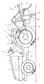
以下に、この発明の実施の形態について図面を参照しながら構成を説明する。図1の符号1は、この発明に係るトラクターを示しており、トラクター1は機体の下部四隅に駆動車輪としての前輪2,2と後輪3,3を備えている。
【0015】
機体前部のボンネット4内にはエンジン5が設けられ、エンジン5の回転動力をミッションケース6内のトロイダル変速装置8に伝達している。トロイダル変速装置8については後述する。
トラクター1の運転席11の前方には計器盤10とステアリングハンドル12と機体の進行方向を切換える前後進切換レバー19が設けられ、運転席11横の操作パネル14には車速設定具としてのダイヤル調整式つまみ7を設けている。このダイヤル調整式つまみ7に代えて従来周知のHSTペダルのような変速ペダル又はパワーシフトのように前後に操作して変速を行なう変速操作レバーを設けても良く、変速ペダルの場合はフロア17の右側に設け、変速操作レバーの場合には操作パネル14に前後方向に移動操作可能に設ける。車速設定具7はポテンショメータで構成されていて、操作量を電圧に換算して後述するコントローラ95に入力する。
【0016】
また、図2から明らかなように、フロア17の右側前部には左右独立したブレーキペダル9a,9bを設け、フロア17の左側前部にはクラッチペダル15を設けている。ブレーキ装置13は機体後部に左右設けられ、右ブレーキペダル9aを踏むと右側ブレーキ装置13aが作動し、左ブレーキペダル9bを踏むと左側ブレーキ装置13が作動する。
【0017】
また、ミッションケース6の後上部には油圧シリンダケース16が設けられ、この油圧シリンダケース16の左右両側にはリフトアーム18,18が回動自由に枢着されている。リフトアーム18,18と機体後下部に枢着したロワーリンク20,20との間にはリフトロッド21,21が介装連結されていて、これらのロワーリンク20,20とリフトロッド21,21とトップリンク22とにより作業機を連結する3点リンク機構23が構成されている。
【0018】
なお、この実施例では、右側のリフトロッドは油圧シリンダー21aで構成され、機体に搭載した傾斜センサー24の信号を受けて3点リンク機構23に連結された作業機85を設定された水平姿勢に制御するように構成している。
作業機の水平制御は従来周知の方法で行なわれ、作業機の左右ローリング角度を設定する傾斜設定器25と、機体の傾斜角度を検出する傾斜センサー24と、機体と作業機85との相対的角度差を検出するストロークセンサ26とにより油圧シリンダー21aの伸縮制御量がコントローラ95で算出され、常に機体が設定された左右傾斜姿勢になるようにコントロールされる。通常は作業機が水平状態になるように制御される。
【0019】
油圧操作レバー27を前後方向に回動操作することにより、油圧シリンダケース16内の油圧シリンダ(図示省略)に作動油が供給されて、あるいは排出されてリフトアーム18,18が昇降回動する。
次に図3に示す動力伝達線図について構成を説明する。
【0020】
エンジン5の回転動力は主クラッチ30を介して動力分配ギヤ32に伝達される。動力分配ギヤ32を固着支持している入力軸34には前後一対の入力ディスク35,35が一体的に設けられ、これらのディスク35,35に対向するように出力ディスク37,37が入力軸34の上に回転自在に遊嵌されている。
【0021】
符号38は入力ディスク35から出力ディスク37に動力を伝達するパワーローラで外周部が両デイスク35,37に常時接するように設けられ、油圧シリンダ40のピストンロッド(図示省略)によりその傾斜角度が適宜変更調節される。
【0022】
なお、前記入力ディスク35と出力ディスク37とパワーローラ38およびパワーローラ38の姿勢を変更する機構をまとめてバリエータVと呼ぶものとする。
入力ディスク35から出力ディスク37へ伝達される回転速度はパワーローラ38の傾斜角度によって変化する。符号39は入力ディスク35を外側から押圧してトルクを調節するトルク制御用ピストンである。油圧により作動し、このトルク制御用ピストン39を軸芯方向に押圧することにより伝達するトルクを加減できる。
【0023】
なお、パワーローラ38が相対的に高い半径位置で入力ディスク35に接すると共に、相対的に低い半径位置で出力ディスク37と接触すると出力ディスク37の回転数は増加し、反対にパワーローラ38が相対的に低い半径位置で入力ディスク35に接すると共に、相対的に高い半径位置で出力ディスク37と接触すると出力ディスク37の回転数は減少する。
【0024】
出力ディスク37にはこれと一体で出力スプロケット41が設けられ、前記入力軸34と平行に設けられた出力軸44上に遊嵌されたカウンタ軸45に固着の入力スプロケット46との間にチェン48が介装されている。
なお、これら出力スプロケット41、入力スプロケット46、チェン48を一組のプーリとベルトからなるベルト伝動機構(図示省略)によって構成しても良い。
【0025】
前記カウンタ軸45の前端にはサンギヤ49が固着され、後端には高速時に入り状態になる高速用油圧クラッチ50が設けられている。
サンギヤ49は遊星ギヤ52と噛み合い、更にこの遊星ギヤ52はインターナルギヤ54と常時噛み合う。
【0026】
インターナルギヤ54は出力軸44と一体的に固着されると共に、遊星ギヤ52を支えるキャリヤ55は低速側の油圧クラッチ58と一体化されている。
また、この低速側の油圧クラッチ58の入力側にはギヤ60が一体的に固着されており、このギヤ60は前記動力分配ギヤ32と常時噛み合っている。
【0027】
従って、低速側油圧クラッチ58が接続されているときには、動力分配ギヤ32からの回転動力がキャリヤ55に支持された遊星ギヤ52に伝達され、一方、バリエータVを介して減速された回転動力がサンギヤ49に伝達され、キャリヤ55及びサンギヤ52の噛み合いによる合成した回転動力がインターナルギヤ54を介して出力軸44に伝達されるように構成している。
【0028】
このようにバリエータVによる増減速操作によって出力軸44には前進から後進までの回転が無段階で取れるようになっている。なお、バリエータVの増減速、言い換えるとパワーローラ38,38の角度調整は、ダイヤル調整式つまみ7によって行なわれるものである(変速ペダル又は変速操作レバーであってもよい)。
【0029】
変速ペダルの場合、変速ペダルを前進側に踏み込むと出力軸44の回転は正転方向(前進側)に回転し、反対に後進側に踏み込むと出力軸44は逆転方向(後進側)に回転して機体を後退させるように構成している。
変速ペダルに代えて変速操作レバーを設けた場合も同様で、変速操作レバーを前方に倒せばその倒し角度に略比例して機体は前進速度を増大させ、逆に変速操作レバーを後方に倒せばそれに応じて後進速度が増大するように構成している。
【0030】
ダイヤル調整式つまみ7の場合には、これを一方の側に回すと前進速が得られ、反対方向に回すと後進速が得られる。前進、後進共に停止位置(中立位置)からつまみ7を大きく回す程進行速度が増大するようにしている。
そして、変速ペダル、変速操作レバー、ダイヤル式調整つまみ7いずれの場合にあっても、車速が速くなると自動的に低速側油圧クラッチ58が切れて高速側油圧クラッチ50が入り、従って、遊星ギヤ機構を全く介さないで高速の回転がギヤ62,63,64,65を順次介して出力軸44に伝達されるようにしている。これらの制御はコントローラ95からの指令によって行なわれる。
【0031】
なお、図3において、符号67は後輪デフ装置、68は最終減速ギヤ機構、70は前輪駆動系に動力を伝える前輪駆動ギヤ、74は前輪増速装置、76は前輪デフ装置である。
前輪増速装置74は従来周知の構造であるため、詳細な説明は省略するが、ステアリングハンドル12を略直進方向に維持して作業をしているときは等速クラッチ74aが接続されて前輪2と後輪3の回転周速が略等しくなり、畦際等でステアリングハンドル12を回動操作したときには増速クラッチ74bが接続されて前輪2の周速が後輪3の周速の約2倍程度に増速されて前輪2が速く回されるように構成している。
【0032】
なお、前輪増速装置74を構成する等速クラッチ74aと増速クラッチ74bは油圧方式のため、いずれも作動させない2輪駆動(後輪のみ駆動)の状態も作り出せ、この実施例では走行モード設定器72を適宜切替えて前後輪の駆動形態を変更するようにしている。したがって、走行モード設定器72を路上走行モードにすると如何なる場合も後輪3しか駆動されず、走行モード設定器72を作業モードに切替えると直進中は等速クラッチ74aが作動して4輪駆動状態になり、旋回時に操舵角センサ93がONになると増速クラッチ74bが作動する。なお、前述の説明から明らかなように、この実施例では、前輪増速装置74が2駆4駆切換装置を兼ねる構成としている。この実施例のような前輪増速装置によらず単純な油圧クラッチを介装して2駆と4駆の切換えを行なうように構成してもよい。
【0033】
図3において、PTO駆動系について説明すると、動力分配ギヤ32の回転はPTO駆動軸75上のPTO入力ギヤ77に伝達され、更にPTOクラッチ78、PTO変速装置80を順次介して機体後部に設けられたPTO軸82に伝達される。PTOクラッチ78は油圧方式であり、ステアリングハンドル12あるいは運転席11の近傍に設けたスイッチを押すことにより走行系とは独立して動力を入切できる。
【0034】
次にトラクター1の後部に連結されたロータリ耕耘装置85の構成を説明すると、ロータリ耕耘装置85は耕耘軸86とこの耕耘軸86に取り付けられた耕耘爪87とこれらの上方を覆う耕耘カバー88と後部カバー89等からなり、本機側に設けた耕深設定器90で設定した耕耘深さとなるように油圧昇降機構が制御される。このため、ロータリ耕耘装置85側には耕深センサ92が設けられ、この耕深センサ92は耕耘カバー88の後部に取り付けられ、後部カバー89の揺動角を耕深変化として捉えるようにしている。後述するが、前記耕深設定器90による設定値と耕深センサ92による検出値が常時比較され、設定耕深となうようにコントローラ95から油圧昇降装置の上昇用比例弁96と下降用比例弁97に対して制御指令が出される。
【0035】
図4は本願発明に係る制御系のブロック図であり、構成を説明すると、マイコンからなるコントローラ95の入力側には前記耕深設定器90と耕深センサ92と車速設定器7が接続されている。ここで云う車速設定器7は前述の通り変速ペダル又は変速操作レバー又はダイヤル調整式つまみであり、これらのうちの1つがコントローラ95に接続されてバリエータの一部を構成する油圧シリンダ40を制御する。変速制御に必要な車速センサー73も接続されている。
【0036】
その他、前後進切換レバー19の切換位置を検出する前後進切換スイッチ94、操舵角センサー93、走行モード設定器72、傾斜センサー24、傾斜設定器25、ストロークセンサー26、機体のダッシングを感知する衝撃感知センサー98、パワーローラ38作動用オイルの油温感知センサー99がコントローラ95の入力側に接続されている。
【0037】
一方、コントローラ95の出力側にはパワーローラ38の傾き調節用油圧シリンダ40を伸縮させる伸長用ソレノイド40aと短縮用ソレノイド40bが接続され、さらにリフトアーム18を昇降回動させる上昇用比例弁96と下降用比例弁97が接続され、これら以外に前輪増速用ソレノイド101と等速用ソレノイド102が接続されている。
【0038】
次に作用を説明する。
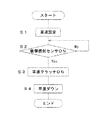
前記コントローラ95を搭載したトラクター1を用いて耕耘作業を行なう場合には、図5に示すように、まず、車速設定具7で耕耘作業速度を決定し(ステップS1)、ロータリ耕耘装置85に動力を伝達させた状態で作業機を着地させる。このとき、圃場が硬い場合には回転する耕耘爪87により機体全体が前方に大きく飛び出すほどの推進力を受けることになるが、このような場合には衝撃感知センサー98がONとなり(ステップS2)、2駆4駆切換装置を兼ねる前輪増速装置74が等速側に切換えられ、同時にトロイダル変速装置8が車速低側に切換えられる(ステップS3,S4)。
【0039】
このため、前輪2と後輪3に同時に動力が伝達される状態になり、前輪2が後輪3に対してブレーキとなると共に、車速も減速されるので機体の飛び出しが防止される。
そして、ロータリ耕耘装置85を着地後、水平制御機構を働かせて耕耘作業を行なうと、トラクター1の左右ローリングに拘わらずロータリ耕耘装置85を常時水平に維持すべく油圧シリンダ21aが伸縮作動してロータリ耕耘装置85が左右水平姿勢に維持される。
【0040】
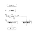
水平制御中は、同時にトラクター1の車速を設定された車速に維持する車速制御も行なわれているのであるが、パワーローラ38に対する制御出力とロータリ耕耘装置85に対する水平制御出力が同時に出たときには、図6のフローチャートに示すように水平制御が優先され、車速を維持するために必要なパワーローラ38に対する制御出力は一時的にカットされる。
【0041】
この発明では、作業機が水平に復帰してから車速制御を実行させるものであるから、耕耘跡が美麗であり、後工程で実施される畦立作業や播種作業等に支障を与えることがない。
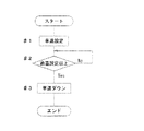
また、作業中にパワーローラ38伸縮制御用の油圧オイルの温度が異常に高くなると、トロイダル変速装置8の作動異常を招く恐れがあるが、この発明では図7のフローチャートに示すように、油温が設定された温度を越えて異常に高くなる場合にはその作動に制限を加える方向の制御が実施される。この発明では、車速を増速する方向にパワーローラ38の傾きが修正される制御は許可されず、減速方向のみ可能になるように制御される。したがって、油温がさらに上昇してトロイダル変速装置8が異常を起こす不具合が回避されるものである。
【0042】
なお、図示は省略するが、前述のトラクター1において、坂道での機体の暴走を防止するために機体が停止したときに前後輪2,3にトルクのみ伝わるギヤードニュートラル状態を作り出すようにバリエータのトルク制御用ピストン39を制御することも可能である。この場合には、前後進切換レバー19を中立にしたとき、あるいはクラッチペダル15かブレーキペダル9を踏み込んだときに前記トルク制御用ピストン39を作動させて出力ディスク37を押さえつけるようにする。このようにすることによって、例えばクラッチペダル15を長時間踏み続けていても機体が坂道を暴走するようなことはない。
【0043】
【発明の効果】
本発明は、以上説明したような形態で実施され、以下に記載されるような効果を奏する。
即ち、請求項1記載の発明では、2駆4駆切換装置を備え、エンジン5からの動力をミッションケース6内のトロイダル型変速機8に伝えて車輪2,3を駆動する動力車両1において、運転席11の近傍に前記トロイダル型変速機8のパワーローラ38の角度を制御する車速設定具7を設け、機体後部に装着した対地作業機を下降接地させた際に機体を前進させる所定以上の推進力を受けたときには前記2駆4駆切換装置を4駆側に切換え、さらに前記トロイダル型変速機8を車速減側に切換える制御手段を設けたので、硬い圃場で機体がダッシングするような危険性がなく安全に作業を行なえる。
【0044】
また、請求項2の発明は、エンジン5からの動力をミッションケース6内のトロイダル型変速機8に伝えて車輪2,3を駆動する動力車両1の後部に対地作業機を左右ローリング自在に連結し、本機側には機体の左右傾斜量を検出する傾斜センサと前記トロイダル型変速機8のパワーローラ38の角度を制御する車速設定具7を設け、対地作業機を所定の姿勢に維持させるべく水平制御の出力が生じているときには、前記トロイダル型変速機8に対する変速制御を中断し、水平出力が停止した時点で変速制御を可能としたので、作業精度が向上し、耕耘跡を美麗にすることができる。
【0045】
また、請求項3の発明は、エンジン5からの動力をミッションケース6内のトロイダル型変速機8に伝えて車輪2,3を駆動する動力車両1において、運転席11の近傍に前記トロイダル型変速機8のパワーローラ38の角度を制御する車速設定具7を設け、前記トロイダル型変速機8のパワーローラ38を制御する油圧オイルの油温が所定値以上に上昇したときには車速上昇側の制御出力を一時的に停止させる制御手段を設けたので、負荷が増大し続けることによるトロイダル型変速機8の機械的トラブルを避けることができる。
【図面の簡単な説明】
【図1】トラクターとロータリ耕耘装置の側面図である。
【図2】トラクターの平面図である。
【図3】動力伝達線図である。
【図4】制御ブロック図である。
【図5】フローチャートである。
【図6】フローチャートである。
【図7】フローチャートである。
【符号の説明】
1 トラクター
2 前輪
3 後輪
4 ボンネット
5 エンジン
6 ミッションケース
7 車速設定具(ダイヤル調整式つまみ)
8 トロイダル変速装置
9 ブレーキペダル
10 計器盤
11 運転席
12 ステアリングハンドル
14 操作パネル
15 クラッチペダル
19 前後進切換レバー
24 傾斜センサ
38 パワーローラ
40 油圧シリンダ
85 対地作業機(ロータリ耕耘装置)
95 制御手段(コントローラ)[0001]
TECHNICAL FIELD OF THE INVENTION
INDUSTRIAL APPLICABILITY The present invention can be used for a transmission of a powered vehicle such as a tractor, a riding lawn mower, and a riding management machine.
[0002]
[Prior art]
2. Description of the Related Art In recent years, continuously variable transmissions have been mounted on power agricultural machines such as tractors and riding lawn mowers in order to improve operability and workability.
The most convenient method of the continuously variable transmission is to perform a speed change on the output pulley side by winding a belt between two sets of split pulleys and changing the gap between the pulleys (for example, see Patent Document 1).
[0003]
As an alternative to belt transmission, there is also known a device equipped with a hydrostatic continuously variable transmission (so-called HST) (for example, see Patent Document 2).
[0004]
[Patent Document 1]
Japanese Patent Application Laid-Open No. 12-225863 (FIG. 4)
[Patent Document 2]
JP-A No. 12-16102 (FIG. 2)
[0005]
[Problems to be solved by the invention]
By the way, in the above-mentioned conventional tractor, heat problems may occur in belt transmission, and the durability of the belt often decreases at high temperatures. In the case of a hydrostatic continuously variable transmission, the transmission efficiency is reduced. However, there is a drawback in that it is inferior to a mechanical transmission in that point.
[0006]
[Means for Solving the Problems]
INDUSTRIAL APPLICABILITY The present invention is excellent in mechanical transmission efficiency, furthermore, can easily perform gear shifting operation, can prevent dashing of the machine body at the start of farming work, can prevent trouble of the transmission due to oil temperature rise during farming work, and can perform horizontal control. It is another object of the present invention to provide a power vehicle that can reliably perform the operation.
[0007]
For this reason, the following technical measures were taken.
That is, according to the first aspect of the present invention, there is provided a powered vehicle 1 having a two-wheel drive four-wheel drive switching device and transmitting power from an engine 5 to a toroidal type transmission 8 in a transmission case 6 to drive wheels 2 and 3. A vehicle speed setting device 7 for controlling the angle of the power roller 38 of the toroidal transmission 8 in the vicinity of the driver's seat 11 to advance the machine when the ground work machine attached to the rear of the machine descends and touches the ground; A control unit 95 for switching the two-wheel drive four-wheel drive switching device to the four-wheel drive side when the vehicle receives the propulsion force of the vehicle body, and for switching the toroidal type transmission 8 to the vehicle speed reduction side. The structure of the transmission was adopted.
[0008]
According to a second aspect of the present invention, a ground working machine 85 is connected to the rear portion of the power vehicle 1 that transmits the power from the engine 5 to the toroidal type transmission 8 in the transmission case 6 to drive the wheels 2 and 3 so as to freely roll left and right. On the machine side, an inclination sensor 24 for detecting the amount of lateral inclination of the body and a vehicle speed setting tool 7 for controlling the angle of the power roller 38 of the toroidal type transmission 8 are provided, and the ground work machine 85 is set to a predetermined inclination posture. When the output of the horizontal control is generated to maintain the transmission, the shift control for the toroidal transmission 8 is interrupted, and the shift control is enabled when the horizontal output is stopped. Configuration.
[0009]
According to the third aspect of the present invention, in the power vehicle 1 that transmits the power from the engine 5 to the toroidal type transmission 8 in the transmission case 6 to drive the wheels 2 and 3, the toroidal type is provided near the driver's seat 11. The vehicle speed setting device 7 for controlling the angle of the power roller 38 of the transmission 8 is provided, and the oil temperature of the hydraulic oil flowing into and out of the hydraulic cylinder 40 for controlling the power roller 38 of the toroidal type transmission 8 becomes higher than a predetermined value. A control device 95 for temporarily stopping the control output on the vehicle speed increasing side when the vehicle speed rises is provided.
[0010]
[Action]
When the rotation of the engine 5 is transmitted to the input shaft 34 of the toroidal transmission 8, the input disk 35 is driven to rotate. When the vehicle speed setting device 7 is operated, the inclination angle of the power roller 38 with respect to the output disk 37 is changed to adjust the reduction ratio, and the rotational speed of the drive wheels 2 and 3 is reduced by the differential with the planetary mechanism provided on the lower side of the transmission. Change adjusted.
[0011]
A four-wheel drive state in which power is also transmitted to the front wheels 2 when receiving a large propulsive force from the working machine side to advance the machine body when a working machine such as a rotary tilling device connected to the rear of the machine body lands. At the same time, the vehicle speed is reduced by a command from the controller.
[0012]
When a control signal is output to the hydraulic cylinder 21a for horizontal control when performing the tilling operation while performing the horizontal control using the rotary tilling device, the shift control by the toroidal transmission 8 is temporarily cut, Horizontal control has priority. Further, when the temperature of oil flowing into and out of the hydraulic cylinder 40 for adjusting the inclination of the power roller 38 becomes abnormally high, the shift control in the direction of increasing the speed is interrupted.
[0013]
Due to such an action, even when the soil of the field is hard, there is no danger of the body being dashed at the start of the work, and the tilling work can be performed safely and efficiently, and the horizontal control using the rotary tilling device has an accuracy. It can be done well.
[0014]
BEST MODE FOR CARRYING OUT THE INVENTION
Embodiments of the present invention will be described below with reference to the drawings. Reference numeral 1 in FIG. 1 indicates a tractor according to the present invention. The tractor 1 includes front wheels 2, 2 and rear wheels 3, 3 as drive wheels at four lower corners of the fuselage.
[0015]
An engine 5 is provided in a hood 4 at the front of the machine body, and transmits the rotational power of the engine 5 to a toroidal transmission 8 in a transmission case 6. The toroidal transmission 8 will be described later.
In front of the driver's seat 11 of the tractor 1, an instrument panel 10, a steering handle 12, and a forward / reverse switching lever 19 for switching the traveling direction of the aircraft are provided. An operation panel 14 beside the driver's seat 11 has a dial adjustment as a vehicle speed setting tool. An expression knob 7 is provided. Instead of the dial-adjustable knob 7, a shift pedal such as a conventionally known HST pedal or a shift operation lever for shifting the gear by operating back and forth such as a power shift may be provided. It is provided on the right side, and in the case of a shift operation lever, it is provided on the operation panel 14 so as to be movable in the front-rear direction. The vehicle speed setting device 7 is constituted by a potentiometer, and converts an operation amount into a voltage and inputs the voltage to a controller 95 described later.
[0016]
2, the left and right independent brake pedals 9a and 9b are provided on the right front portion of the floor 17, and the clutch pedal 15 is provided on the left front portion of the floor 17. The brake devices 13 are provided on the right and left rear portions of the fuselage. When the right brake pedal 9a is depressed, the right brake device 13a operates, and when the left brake pedal 9b is depressed, the left brake device 13 operates.
[0017]
A hydraulic cylinder case 16 is provided at the rear upper portion of the transmission case 6, and lift arms 18, 18 are pivotally mounted on both left and right sides of the hydraulic cylinder case 16. Lift rods 21 and 21 are interposed and connected between the lift arms 18 and 18 and the lower links 20 and 20 pivotally attached to the lower rear part of the fuselage. These lower links 20 and 20 and the lift rods 21 and 21 are connected to each other. A three-point link mechanism 23 that connects the work implements with the top link 22 is configured.
[0018]
In this embodiment, the lift rod on the right side is constituted by a hydraulic cylinder 21a, and receives a signal from the tilt sensor 24 mounted on the machine body to move the working machine 85 connected to the three-point link mechanism 23 to the set horizontal posture. It is configured to control.
The horizontal control of the working machine is performed by a conventionally known method, and a tilt setting device 25 for setting the left and right rolling angles of the working machine, a tilt sensor 24 for detecting a tilt angle of the machine, and a relative position between the machine and the working machine 85. The expansion / contraction control amount of the hydraulic cylinder 21a is calculated by the controller 95 by the stroke sensor 26 that detects the angle difference, and is controlled so that the machine body always has the set left-right tilt posture. Normally, the work machine is controlled to be in a horizontal state.
[0019]
When the hydraulic operation lever 27 is rotated in the front-rear direction, hydraulic oil is supplied to or discharged from a hydraulic cylinder (not shown) in the hydraulic cylinder case 16, and the lift arms 18, 18 are vertically rotated.
Next, the configuration will be described with reference to the power transmission diagram shown in FIG.
[0020]
The rotational power of the engine 5 is transmitted to the power distribution gear 32 via the main clutch 30. A pair of front and rear input disks 35, 35 are integrally provided on an input shaft 34 fixedly supporting the power distribution gear 32, and output disks 37, 37 are connected to the input shaft 34 so as to face these disks 35, 35. Is rotatably loosely fitted on the top.
[0021]
Reference numeral 38 denotes a power roller for transmitting power from the input disk 35 to the output disk 37, the outer peripheral portion of which is always in contact with the disks 35 and 37, and the inclination angle of which is appropriately adjusted by a piston rod (not shown) of the hydraulic cylinder 40. Change adjusted.
[0022]
The input disk 35, the output disk 37, the power roller 38, and a mechanism for changing the attitude of the power roller 38 are collectively referred to as a variator V.
The rotation speed transmitted from the input disk 35 to the output disk 37 changes according to the inclination angle of the power roller 38. Reference numeral 39 denotes a torque control piston for adjusting the torque by pressing the input disk 35 from the outside. It operates by hydraulic pressure, and the torque transmitted by pressing the torque control piston 39 in the axial direction can be adjusted.
[0023]
When the power roller 38 contacts the input disk 35 at a relatively high radial position and contacts the output disk 37 at a relatively low radial position, the rotation speed of the output disk 37 increases. When it comes into contact with the input disk 35 at an extremely low radial position and contacts the output disk 37 at a relatively high radial position, the rotational speed of the output disk 37 decreases.
[0024]
The output disk 37 is provided with an output sprocket 41 integrally therewith. A chain 48 is provided between the output disk 37 and an input sprocket 46 fixed to a counter shaft 45 loosely fitted on an output shaft 44 provided in parallel with the input shaft 34. Is interposed.
The output sprocket 41, the input sprocket 46, and the chain 48 may be configured by a belt transmission mechanism (not shown) including a set of pulleys and a belt.
[0025]
A sun gear 49 is fixed to the front end of the counter shaft 45, and a high-speed hydraulic clutch 50 is provided at the rear end of the counter shaft 45 to enter a high-speed state.
The sun gear 49 meshes with the planetary gear 52, and the planetary gear 52 constantly meshes with the internal gear 54.
[0026]
The internal gear 54 is fixed integrally with the output shaft 44, and the carrier 55 supporting the planetary gear 52 is integrated with a low-speed hydraulic clutch 58.
A gear 60 is integrally fixed to the input side of the low-speed hydraulic clutch 58, and the gear 60 is always meshed with the power distribution gear 32.
[0027]
Therefore, when the low-speed side hydraulic clutch 58 is connected, the rotational power from the power distribution gear 32 is transmitted to the planetary gear 52 supported by the carrier 55, while the rotational power reduced via the variator V is transmitted to the sun gear. The transmission is transmitted to the output shaft 44 via the internal gear 54 and transmitted to the output shaft 49 via the internal gear 54.
[0028]
As described above, the output shaft 44 can rotate from the forward movement to the reverse movement in a stepless manner by the acceleration / deceleration operation by the variator V. The speed up / down of the variator V, in other words, the angle adjustment of the power rollers 38, 38 is performed by the dial adjustment knob 7 (may be a speed change pedal or a speed change operation lever).
[0029]
In the case of a speed change pedal, when the speed change pedal is depressed forward, the rotation of the output shaft 44 rotates in the forward direction (forward direction), and when depressed backward, the output shaft 44 rotates in the reverse direction (reverse direction). The aircraft is configured to retreat.
The same applies when a gearshift lever is provided in place of the gearshift pedal.If the gearshift lever is tilted forward, the aircraft increases the forward speed substantially in proportion to the tilt angle, and conversely, if the gearshift lever is tilted backward The reverse speed is configured to increase accordingly.
[0030]
In the case of the dial-adjustable knob 7, turning it to one side provides a forward speed, and turning it in the opposite direction provides a reverse speed. In both forward and backward travel, the more the knob 7 is turned from the stop position (neutral position), the faster the traveling speed increases.
In any of the shift pedal, the shift operation lever, and the dial-type adjustment knob 7, when the vehicle speed increases, the low-speed side hydraulic clutch 58 is automatically disengaged and the high-speed side hydraulic clutch 50 is engaged. , And the high-speed rotation is transmitted to the output shaft 44 via the gears 62, 63, 64, 65 sequentially. These controls are performed by commands from the controller 95.
[0031]
In FIG. 3, reference numeral 67 denotes a rear wheel differential device, 68 denotes a final reduction gear mechanism, 70 denotes a front wheel drive gear for transmitting power to a front wheel drive system, 74 denotes a front wheel speed increasing device, and 76 denotes a front wheel differential device.
Since the front wheel speed increasing device 74 has a conventionally well-known structure, a detailed description thereof will be omitted. However, when working while maintaining the steering handle 12 in a substantially straight traveling direction, the constant speed clutch 74a is connected and the front wheel 2 When the steering wheel 12 is rotated around a ridge or the like, the rotational speed of the front wheel 2 is approximately equal to the peripheral speed of the rear wheel 3 when the steering wheel 12 is rotated. The front wheel 2 is configured to be rotated at a high speed so that the front wheel 2 is rotated quickly.
[0032]
Since the constant speed clutch 74a and the speed increasing clutch 74b constituting the front wheel speed increasing device 74 are of a hydraulic system, it is possible to create a two-wheel drive state (drive only the rear wheels) in which neither is operated. The drive mode of the front and rear wheels is changed by appropriately switching the device 72. Therefore, when the traveling mode setting device 72 is set to the road traveling mode, only the rear wheels 3 are driven in any case. When the traveling mode setting device 72 is switched to the work mode, the constant speed clutch 74a operates during straight traveling to drive the four wheels. When the steering angle sensor 93 is turned on during turning, the speed increasing clutch 74b operates. In addition, as is clear from the above description, in this embodiment, the front wheel speed increasing device 74 is configured to also serve as the 2WD / 4WD switching device. Instead of using the front wheel speed increasing device as in this embodiment, a simple hydraulic clutch may be provided to switch between the two-wheel drive and the four-wheel drive.
[0033]
Referring to FIG. 3, the PTO drive system will be described. The rotation of the power distribution gear 32 is transmitted to a PTO input gear 77 on a PTO drive shaft 75, and further provided at a rear portion of the body via a PTO clutch 78 and a PTO transmission 80 in order. Is transmitted to the PTO shaft 82. The PTO clutch 78 is a hydraulic system, and can turn on and off power independently of the traveling system by pressing a switch provided near the steering handle 12 or the driver's seat 11.
[0034]
Next, the configuration of the rotary tilling device 85 connected to the rear portion of the tractor 1 will be described. The rotary tilling device 85 includes a tilling shaft 86, a tilling claw 87 attached to the tilling shaft 86, and a cultivating cover 88 for covering the upper portion thereof. The hydraulic elevating mechanism is controlled to have the tillage depth set by the tillage depth setting device 90 provided on the machine side, including the rear cover 89 and the like. For this reason, a tillage depth sensor 92 is provided on the rotary tillage device 85 side, and this tillage depth sensor 92 is attached to the rear part of the tillage cover 88 so that the swing angle of the rear cover 89 is regarded as a tillage depth change. . As will be described later, the set value of the tillage depth setting device 90 and the detection value of the tillage depth sensor 92 are constantly compared, and the controller 95 controls the ascending proportional valve 96 and the descending proportional valve of the hydraulic elevating device so as to achieve the set tillage depth. A control command is issued to the valve 97.
[0035]
FIG. 4 is a block diagram of a control system according to the present invention. To explain the configuration, an input side of a controller 95 composed of a microcomputer is connected with the tillage depth setting device 90, the tillage depth sensor 92, and the vehicle speed setting device 7. I have. As described above, the vehicle speed setting device 7 is a speed change pedal, a speed change operation lever, or a dial-adjustable knob, one of which is connected to the controller 95 to control the hydraulic cylinder 40 which forms a part of the variator. . A vehicle speed sensor 73 required for gear shift control is also connected.
[0036]
In addition, a forward / backward changeover switch 94 for detecting a switching position of the forward / backward changeover lever 19, a steering angle sensor 93, a traveling mode setting unit 72, an inclination sensor 24, an inclination setting unit 25, a stroke sensor 26, and an impact for detecting dashing of the body. A sensor 98 and an oil temperature sensor 99 for operating the power roller 38 are connected to the input side of the controller 95.
[0037]
On the other hand, the output side of the controller 95 is connected with an extension solenoid 40a and a shortening solenoid 40b that expand and contract the tilt adjusting hydraulic cylinder 40 of the power roller 38, and further includes an ascending proportional valve 96 that moves the lift arm 18 up and down. A lowering proportional valve 97 is connected, and in addition, a front wheel speed increasing solenoid 101 and a constant speed solenoid 102 are connected.
[0038]
Next, the operation will be described.
When performing the tilling work using the tractor 1 equipped with the controller 95, as shown in FIG. 5, first, the tilling work speed is determined by the vehicle speed setting tool 7 (step S1). The work machine is landed in the state where the is transmitted. At this time, if the field is hard, the rotating tilling claw 87 receives a propulsive force such that the entire body largely jumps forward, but in such a case, the impact sensor 98 is turned on (step S2). The front wheel speed increasing device 74 also serving as the 2WD / 4WD switching device is switched to the constant speed side, and at the same time, the toroidal transmission 8 is switched to the low vehicle speed side (steps S3 and S4).
[0039]
As a result, power is simultaneously transmitted to the front wheel 2 and the rear wheel 3, and the front wheel 2 acts as a brake for the rear wheel 3 and the vehicle speed is reduced, so that the body is prevented from jumping out.
Then, after the rotary tilling device 85 lands, when the tilling operation is performed by operating the horizontal control mechanism, the hydraulic cylinder 21a expands and contracts to maintain the rotary tilling device 85 constantly horizontal regardless of the left and right rolling of the tractor 1, and the rotary The tilling device 85 is maintained in a horizontal posture.
[0040]
During the horizontal control, vehicle speed control for maintaining the vehicle speed of the tractor 1 at the set vehicle speed is also performed at the same time. However, when the control output for the power roller 38 and the horizontal control output for the rotary tillage device 85 are simultaneously output, As shown in the flow chart of FIG. 6, priority is given to the horizontal control, and the control output to the power roller 38 necessary for maintaining the vehicle speed is temporarily cut off.
[0041]
In the present invention, since the vehicle speed control is executed after the work machine returns to the horizontal state, the cultivation marks are beautiful, and there is no hindrance to the ridge work, the seeding work, and the like performed in the subsequent process. .
Further, if the temperature of the hydraulic oil for controlling the expansion and contraction of the power roller 38 becomes abnormally high during the operation, the operation of the toroidal transmission 8 may be abnormally operated. In the present invention, as shown in the flowchart of FIG. If the temperature exceeds the set temperature and becomes abnormally high, control is performed in a direction to limit the operation. In the present invention, the control for correcting the inclination of the power roller 38 in the direction of increasing the vehicle speed is not permitted, and the control is performed so that only the deceleration direction is possible. Therefore, it is possible to avoid a problem that the oil temperature is further increased and the toroidal transmission 8 causes an abnormality.
[0042]
Although not shown, in the tractor 1 described above, the variator torque is set so as to create a geared neutral state in which only the torque is transmitted to the front and rear wheels 2 and 3 when the aircraft stops to prevent runaway of the aircraft on a slope. It is also possible to control the control piston 39. In this case, when the forward / reverse switching lever 19 is neutralized, or when the clutch pedal 15 or the brake pedal 9 is depressed, the torque control piston 39 is operated to hold down the output disk 37. By doing so, for example, even if the clutch pedal 15 is continuously depressed for a long time, the aircraft does not run away on a slope.
[0043]
【The invention's effect】
The present invention is implemented in the form described above, and has the following effects.
That is, according to the first aspect of the present invention, there is provided a powered vehicle 1 including a two-wheel drive four-wheel drive switching device, transmitting power from an engine 5 to a toroidal type transmission 8 in a transmission case 6 to drive wheels 2 and 3. A vehicle speed setting tool 7 for controlling the angle of the power roller 38 of the toroidal type transmission 8 is provided near the driver's seat 11, and the ground work machine mounted on the rear of the body is moved downward when the ground work machine is brought into contact with the ground. When the propulsion force is applied, the control unit switches the 2WD 4WD switching device to the 4WD side and further switches the toroidal type transmission 8 to the vehicle speed decreasing side. It is safe to work without any difficulty.
[0044]
According to the invention of claim 2, the ground working machine is connected to the rear portion of the power vehicle 1 that transmits the power from the engine 5 to the toroidal type transmission 8 in the transmission case 6 to drive the wheels 2 and 3 so as to be freely rollable left and right. An inclination sensor for detecting the amount of inclination of the body from side to side and a vehicle speed setting tool 7 for controlling the angle of the power roller 38 of the toroidal type transmission 8 are provided on the machine side to maintain the ground work machine in a predetermined posture. Therefore, when the output of the horizontal control is generated, the shift control for the toroidal type transmission 8 is interrupted, and the shift control is enabled when the horizontal output is stopped, so that the working accuracy is improved and the till marks are beautifully cleaned. can do.
[0045]
Further, in the power vehicle 1 that drives the wheels 2 and 3 by transmitting the power from the engine 5 to the toroidal transmission 8 in the transmission case 6, the toroidal transmission is provided near the driver's seat 11. A vehicle speed setting device 7 for controlling the angle of the power roller 38 of the machine 8 is provided. When the temperature of the hydraulic oil for controlling the power roller 38 of the toroidal transmission 8 rises above a predetermined value, the control output on the vehicle speed increasing side is output. Is provided, the mechanical trouble of the toroidal type transmission 8 due to the continuous increase of the load can be avoided.
[Brief description of the drawings]
FIG. 1 is a side view of a tractor and a rotary tilling device.
FIG. 2 is a plan view of the tractor.
FIG. 3 is a power transmission diagram.
FIG. 4 is a control block diagram.
FIG. 5 is a flowchart.
FIG. 6 is a flowchart.
FIG. 7 is a flowchart.
[Explanation of symbols]
Reference Signs List 1 tractor 2 front wheel 3 rear wheel 4 bonnet 5 engine 6 transmission case 7 vehicle speed setting tool (dial adjustable knob)
8 Toroidal transmission 9 Brake pedal 10 Instrument panel 11 Driver's seat 12 Steering handle 14 Operation panel 15 Clutch pedal 19 Forward / reverse switching lever 24 Inclination sensor 38 Power roller 40 Hydraulic cylinder 85 Ground work machine (rotary tilling device)
95 Control means (controller)