JP2004237588A - Inkjet recorder - Google Patents
Inkjet recorder Download PDFInfo
- Publication number
- JP2004237588A JP2004237588A JP2003029381A JP2003029381A JP2004237588A JP 2004237588 A JP2004237588 A JP 2004237588A JP 2003029381 A JP2003029381 A JP 2003029381A JP 2003029381 A JP2003029381 A JP 2003029381A JP 2004237588 A JP2004237588 A JP 2004237588A
- Authority
- JP
- Japan
- Prior art keywords
- recording
- ink
- recording medium
- nozzles
- recording apparatus
- Prior art date
- Legal status (The legal status is an assumption and is not a legal conclusion. Google has not performed a legal analysis and makes no representation as to the accuracy of the status listed.)
- Pending
Links
Images


Landscapes
- Ink Jet (AREA)
Abstract
Description
【0001】
【発明の属する技術分野】
本発明はインクジェット記録装置、特に光硬化性のインクを用いたインクジェット記録装置に関する。
【0002】
【従来の技術】
近年、紙などの記録媒体に画像を記録する装置として、記録媒体の表面に光硬化性のインクを吐出する光硬化インクジェット方式のインクジェット記録装置が良く知られている。このインクジェット記録装置は、図11に示すように、下方の記録媒体に向かってインクを吐出する複数のノズル100,…を有する記録ヘッド101と、記録媒体の表面に着弾したインクに紫外線などの光を照射する照射装置102とを備えている(例えば、特許文献1参照)。
より詳細には、照射装置102は水銀ランプ等の点光源103を1つ有しており、この点光源103は、記録媒体の表面に着弾したインク全体を硬化させるべく、広い領域に対し光を拡散させて照射することができるようになっている。
【0003】
【特許文献1】
特開2001−310454号公報
【0004】
【発明が解決しようとする課題】
しかしながら、上記のような照射装置102によって記録媒体の表面のインクを硬化させる場合には、インクが着弾していない領域の記録媒体や照射装置102の構成部材等にも光が照射されるため、エネルギーが無駄になるとともに、光によって照射装置102や記録媒体が劣化するという問題があった。特にこのような問題は、文字を主としたドキュメントの記録を行う場合など、記録媒体の表面における僅かな領域のみにインクを着弾させて記録を行う場合に顕著となっていた。
また、画像の階調を表現する場合、つまり一画素に対して吐出されるインクの液滴数や形成されるドット径を変化させる場合であっても、これらインクの液滴数やドット径に関わらず照射装置102によって一定量の光が照射されていた。そのため、インクの硬化に関与しない過剰な光が照射されることとなる結果、エネルギーが無駄になるとともに、照射装置102や記録媒体が劣化するという問題が生じていた。
【0005】
本発明の課題は、エネルギーの無駄が少なく、記録媒体及び照射装置が劣化し難いインクジェット記録装置を提供することを目的とする。
【0006】
【課題を解決するための手段】
請求項1記載の発明は、記録媒体に向かって光硬化性のインクを吐出する複数のノズルを有する記録ヘッドと、
前記記録媒体に着弾したインクに光を照射する照射装置と、
前記記録ヘッド及び前記照射装置を制御する制御装置とを備えるインクジェット記録装置において、
前記制御装置は、インクの吐出に関する前記記録ヘッドの制御条件に基づいて前記照射装置を制御することを特徴とする。
【0007】
ここで、記録ヘッドの制御条件とは、例えばインクを吐出するか否かに関する条件や、インクの吐出量に関する条件などである。
請求項1記載の発明によれば、制御装置は記録ヘッドの制御条件に基づいて照射装置を制御するので、従来と異なり、文字を主としたドキュメントの記録を行う場合であっても、インクが着弾していない領域の記録媒体や、照射装置の構成部材などに無駄な光が照射されることを抑えることができる。また、インクの液滴数又はドット径を変化させることによって画像の階調を表現する場合であっても、従来と異なり、一画素に対して吐出されたインクの液滴数や形成されたドット径に基づいて光を照射することができるため、インクの硬化に関与しない過剰な光が記録媒体や照射装置の構成部材などに当たることを防ぐことができる。
以上により、エネルギーの無駄を省くとともに、光による記録媒体や照射装置の劣化を抑えることができる。
【0008】
請求項2記載の発明は、請求項1記載のインクジェット記録装置において、
前記記録媒体を搬送方向に搬送する搬送装置を備え、
前記記録ヘッドはラインヘッドであり、前記複数のノズルは前記搬送方向の略直交方向に沿って一列以上配列され、
前記照射装置は複数の点光源を備え、これら複数の点光源は、各ノズルに対応して、このノズルよりも前記搬送方向の下流側に配置され、
前記制御装置は、前記制御条件に基づいて前記照射装置の各点光源を制御することを特徴とする。
【0009】
請求項2記載の発明によれば、複数の点光源は各ノズルに対応してこのノズルよりも搬送方向の下流側に配置され、記録ヘッドの制御条件に基づいて制御されているので、インクが着弾した領域の記録媒体のみを、着弾したインクの液滴数や形成されたドット径に基づいて点灯させることができる。従って、インクが着弾していない領域の記録媒体や、照射装置の構成部材などに無駄な光が照射されることを確実に抑えることができるため、より確実にエネルギーの無駄を省くとともに光による記録媒体や照射装置の劣化を抑えることができる。
【0010】
請求項3記載の発明は、請求項1記載のインクジェット記録装置において、
前記記録媒体を搬送方向に搬送する搬送装置と、
前記搬送方向の略直交方向に沿って前記記録ヘッド及び前記照射装置を前記記録媒体に対して相対移動させる移動装置とを備え、
前記複数のノズルは、前記搬送方向に沿って一列以上配列され、
前記照射装置は複数の点光源を備え、これら複数の点光源は、各ノズルに対応して、このノズルよりも前記略直交方向のうち、少なくとも前記記録ヘッドの移動方向と反対方向の側に配置され、
前記制御装置は、前記制御条件に基づいて前記照射装置の各点光源を制御することを特徴とする。
【0011】
請求項3記載の発明によれば、複数の点光源は各ノズルに対応してこのノズルよりも前記略直交方向のうち、少なくとも記録ヘッドの移動方向と反対方向の側に配置され、記録ヘッドの制御条件に基づいて制御されているので、インクが着弾した領域の記録媒体のみを、着弾したインクの液滴数や形成されたドット径に基づいて点灯させることができる。従って、インクが着弾していない領域の記録媒体や、照射装置の構成部材などに無駄な光が照射されることを確実に抑えることができるため、より確実にエネルギーの無駄を省くとともに光による記録媒体や照射装置の劣化を抑えることができる。
また、複数の点光源は、対応するノズルよりも記録ヘッドの移動方向と反対方向の側に配置されているので、記録媒体に着弾した直後のインクを点光源からの光によって即座に硬化させ、記録媒体の表面上に定着させることができる。従って、インクを滲ませることなく記録を行うことができる。
【0012】
請求項4記載の発明は、請求項3記載のインクジェット記録装置において、
前記搬送装置は、前記記録媒体を間欠的に搬送し、
前記移動装置は、前記記録媒体の搬送が停止する度に前記記録ヘッド及び前記照射装置を前記略直交方向に沿って移動させることによってこれら記録ヘッド及び照射装置を前記記録媒体における同一の記録領域上で前記略直交方向に沿って所定の回数移動させ、
前記制御装置は、各移動の度に所定の間引きパターンで複数の画素を間引きして情報を記録するよう前記記録ヘッドを制御するとともにインクが吐出され得る画素のみに対して光を照射可能となるよう前記照射装置を制御し、これを前記所定の回数繰り返すことによって前記記録領域における情報の記録を完成させることを特徴とする。
【0013】
請求項4記載の発明によれば、各移動の度に所定の間引きパターンで複数の画素を間引きして情報を記録するよう記録ヘッドが制御され、かつインクが吐出され得る画素のみに対して光を照射可能となるよう照射装置が制御されるので、インクが着弾する領域の記録媒体のみに光を照射することができる。従って、より確実にエネルギーの無駄を抑えるとともに光による記録媒体や照射装置の劣化を抑えることができる。
また、記録ヘッドは各移動の度に所定の間引きパターンで複数の画素を間引きして情報を記録し、これを所定の回数繰り返すので、前記略直交方向のラインにおける複数の画素群に対し異なるノズルからインクを吐出することができる。従って、製造誤差によるノズルの向きのズレや、硬化したインクによるノズルの目詰まり等に起因して記録媒体の表面にスジ状の記録欠陥が発生することを防止することができる。更に、記録ヘッドは記録媒体との相対位置を変化させつつ同一の記録領域上で所定の回数移動するので、搬送誤差に起因して記録を行う度に継ぎ目部分に生じる前記略直交方向と平行なスジ状の記録欠陥を、前記搬送方向に分散させ、目立たなくすることができる。従って、記録媒体の表面に高画質の画像を記録することができる。
【0014】
請求項5記載の発明は、請求項2〜4の何れか一項に記載のインクジェット記録装置において、
前記制御装置は、前記記録媒体の表面に1つのドットを形成すべく前記ノズルから吐出されるインクの量に基づいて前記点光源の点灯時間を変化させることを特徴とする。
【0015】
請求項5記載の発明によれば、記録媒体の表面に1つのドットを形成すべくノズルから吐出されるインクの量に基づいて点光源の点灯時間が変化するので、従来と異なり、インクの硬化に関与しない過剰な光が照射されることがない。従って、より確実にエネルギーの無駄を抑えるとともに光による記録媒体や照射装置の劣化を抑えることができる。
【0016】
請求項6記載の発明は、請求項2〜5の何れか一項に記載のインクジェット記録装置において、
前記制御装置は、前記記録媒体の表面に1つのドットを形成すべく前記ノズルから吐出されるインクの量に基づいて前記点光源から前記記録媒体への照射光量を変化させることを特徴とする。
【0017】
請求項6記載の発明によれば、記録媒体の表面に1つのドットを形成すべくノズルから吐出されるインクの量に基づいて点光源から記録媒体への照射光量が変化するので、従来と異なり、インクの硬化に関与しない過剰な光が照射されることがない。従って、より確実にエネルギーの無駄を抑えるとともに光による記録媒体や照射装置の劣化を抑えることができる。
【0018】
請求項7記載の発明は、請求項2〜6の何れか一項に記載のインクジェット記録装置において、
前記点光源は、LED又はLDであることを特徴とする。
【0019】
ここで、LEDとは発光ダイオードのことであり、LDとは半導体レーザのことである。
請求項7記載の発明によれば、点光源がLED又はLDであるので、照射装置を小型軽量でかつ応答性に優れたものとすることができる。従って、インクジェット記録装置を小型化することができるとともに、高い精度で照射装置の制御を行うことができる。
【0020】
請求項8記載の発明は、請求項1〜7の何れか一項に記載のインクジェット記録装置において、
前記ノズルは、紫外線硬化性のインクを吐出し、
前記照射装置は、紫外線を照射することを特徴とする。
【0021】
請求項8記載の発明によれば、熱や電磁波でインクを硬化させる場合と比較して、確実にインクを硬化させることができるとともに、インクジェット記録装置をより小型化することができる。
【0022】
請求項9記載の発明は、請求項1〜8の何れか一項に記載のインクジェット記録装置において、
前記ノズルは、カチオン重合系のインクを吐出することを特徴とする。
【0023】
請求項9記載の発明によれば、ラジカル重合系のインクを用いる場合と比較して、低いエネルギーでインクを硬化させることができる。
【0024】
【発明の実施の形態】
以下、本発明の実施の形態について、図面を参照して説明する。なお、本実施の形態においてはインクジェット記録装置をインクジェットプリンタとして説明する。このインクジェットプリンタは、連続して搬送される記録媒体に対し光硬化性のインクによって所望の画像を記録する装置である。
【0025】
<第1の実施の形態>
図1に示す通り、インクジェットプリンタ1には、画像の記録を行う各種の装置が搭載された画像記録装置2がプラテン4と対向して配設されている。
プラテン4は略水平な上面を有しており、この上面によって記録媒体Kを裏面側から支持している。プラテン4によって支持された記録媒体Kは、図中に矢印で示される搬送方向Aに沿ってローラ等の搬送装置18により間欠的に搬送されている。
【0026】
プラテン4の上方には、搬送方向Aと略直交する方向、つまり走査方向Bに沿って延在するガイド部材5が配設されている。ガイド部材5には、キャリッジ(移動装置)6が支持されている。キャリッジ6は、ガイド部材5によりガイドされた状態で、記録媒体Kの上を走査方向Bに沿って往復運動自在となっている。つまりキャリッジ6は、走査方向Bに沿って記録媒体Kに対し相対移動自在となっている。
【0027】
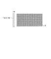
このキャリッジ6には、図2に示すように、イエロー(Y),マゼンタ(M),シアン(C),ブラック(K)の各プロセスカラーのインクを吐出する4つの記録ヘッド7〜10が搭載されている。
これら記録ヘッド7〜10は、走査方向Bに沿って配列されており、インクを吐出する複数のノズル13,…を内部に備えている。複数のノズル13,…は、図2に示すように、搬送方向Aに沿って配列されている。これらノズル13,…は、キャリッジ6に追従して記録ヘッド7〜10が走査方向Bに走査する際に、記録媒体Kに向かってインクを微細な液滴として吐出することができるようになっている。なお、以下の説明においては、便宜的に、各記録ヘッド7〜10にはノズル13がN個(Nは自然数)設けられていることとする。
【0028】
また、記録ヘッド7〜10は、制御装置(図示せず)によって制御された状態でインクを吐出するようになっている。
具体的には、記録ヘッド7〜10は、インクの吐出に関する制御条件に基づいて制御装置によって制御され、これにより画像の階調を表現可能としている。このような制御条件としてはインクを吐出するか否かに関する条件と、記録媒体Kの表面に形成されるべき1つの画素に対して吐出されるインクの液滴数や形成されるドット径に関する条件とがあり、本実施の形態においてはドット径に関する条件が用いられている。
【0029】
また、記録ヘッド7〜10は、製造誤差によるノズル13の向きのズレや、硬化したインクによるノズル13の目詰まり、記録媒体Kの搬送量の誤差などに起因して走査方向Bに沿って記録媒体Kの表面にスジ状の記録欠陥が発生することを防ぐべく、いわゆるインターリーブを行って画像を記録している。ここで、インターリーブとは、走査の度に所定の間引きパターンで複数の画素を間引きして間引き画像を記録し、これを同一の記録領域上で複数回行うことによって画像の記録を完成するものである。
【0030】
以下、インターリーブについて具体的に説明する。なお、以下の説明においては、便宜的に、記録媒体Kの表面の全画素をドットで埋めることによって画像の記録を行うこととする。
インターリーブには、走査方向Bに沿って所定間隔ごとの画素を間引きした間引きパターンで各走査の度に間引き画像を記録する走査インターリーブと、搬送方向Aに沿って所定間隔ごとの画素を間引きした間引きパターンで各走査の度に間引き画像を記録する搬送インターリーブと、走査方向B及び搬送方向Aのそれぞれに沿って所定間隔ごとの画素を間引きした間引きパターンで各走査の度に間引き画像を記録する複合インターリーブとがある。更に、走査インターリーブとしては走査インターリーブ(2)及び走査インターリーブ(3)等があり、搬送インターリーブとしては搬送インターリーブ(2)等があり、複合インターリーブとしては複合インターリーブ(2)等がある。
【0031】
走査インターリーブ(2)は、図3(a)〜(c)に示すように、走査方向Bに沿って1つおきの画素を間引きした2つの間引きパターンを各走査の度に交互に用い、2回の走査によって所定の記録領域上の画像の記録を完成するものである。即ち、走査インターリーブ(2)は、1回目の走査においては、走査方向Bの1ライン上の全画素のうち2分の1の画素を1つおきに埋めていき、2回目の走査においては、1回目の走査で埋められなかった画素を埋めるものである。なお、1回目の走査と2回目の走査との間には、各記録ヘッド7〜10のノズル13のうち、搬送方向Aの最も上流側のノズル13と最も下流側のノズル13との間隔Lの約2分の1の長さだけ記録媒体Kが搬送装置18によって搬送されている。また、図3(a)〜(c)には、記録媒体Kの表面に形成されたドットD,…を黒丸で、形成されるべきドットD,…を白丸で示している。また、図3(c)には、3回目の走査によって形成されるべきドットD,…が図示されている。
【0032】
また、走査インターリーブ(3)は、図4(a)〜(d)に示すように、走査方向Bに沿って2つおきの画素を間引きした3つの間引きパターンを各走査の度に順番に用い、3回の走査によって所定の記録領域上の画像の記録を完成するものである。即ち、走査インターリーブ(3)は、1回目の走査においては走査方向Bの1ライン上の全画素のうち3分の1の画素を2つおきに埋めていき、2回目の走査においては1回目の走査で埋められなかった画素のうち2分の1の画素を2つおきに埋め、3回目の走査においては未だ埋まっていない残りの画素を埋めるものである。なお、各走査の間には、上記間隔Lの約3分の1の長さだけ記録媒体Kが搬送装置18によって搬送されている。また、図4(a)〜(d)には、記録媒体Kの表面に形成されたドットD,…を黒丸で、形成されるべきドットD,…を白丸で示している。また、図4(d)には、4回目の走査によって形成されるべきドットD,…が図示されている。
【0033】
また、搬送インターリーブ(2)は、図5(a)〜(c)に示すように、搬送方向Aに沿って1つおきの画素を間引きした2つの間引きパターンを各走査の度に交互に用い、2回の走査によって所定の記録領域上の画像の記録を完成するものである。即ち、搬送インターリーブ(2)は、1回目の走査においては、搬送方向Aの1ライン上の全画素のうち2分の1の画素を1つおきに埋めていき、2回目の走査においては、1回目の走査で埋められなかった画素を埋めるものである。なお、1回目の走査と2回目の走査との間には、上記間隔Lの約2分の1の長さだけ記録媒体Kが搬送装置18によって搬送されている。また、図5(a)〜(c)には、記録媒体Kの表面に形成されたドットD,…を黒丸で、形成されるべきドットD,…を白丸で示している。また、図5(c)には、3回目の走査によって形成されるべきドットD,…が図示されている。
【0034】
また、複合インターリーブ(2)は、図6(a)〜(e)に示すように、走査方向B及び搬送方向Aのそれぞれに沿って1つおきの画素を間引きした4つの間引きパターンを各走査の度に順番に用い、4回の走査によって所定の記録領域上の画像の記録を完成するものである。即ち、複合インターリーブ(2)は、1回目の走査においては走査方向B及び搬送方向Aのそれぞれの1ライン上の全画素のうち2分の1の画素を1つおきに埋めていき、2回目の走査においては1回目の走査で埋められなかった走査方向Bのライン上の画素を埋めていき、3回目の走査においては1回目の走査で埋められなかった搬送方向Aのライン上の画素をうめていき、4回目の走査においては、未だ埋まっていない残りの画素を埋めるものである。なお、各走査の間には、上記間隔Lの約4分の1の長さだけ記録媒体Kが搬送装置18によって搬送されている。また、図6(a)〜(e)には、記録媒体Kの表面に形成されたドットD,…を黒丸で、形成されるべきドットD,…を白丸で示している。また、図6(e)には、5回目の走査によって形成されるべきドットD,…が図示されている。
【0035】
なお、以下の説明においては、制御装置は、上記インターリーブのうち、走査インターリーブ(2)を行わせるよう記録ヘッド7〜10を制御するものとして説明する。
【0036】
またキャリッジ6には、下方の記録媒体Kに向けて紫外線を照射する照射装置11,12が搭載されている。これら照射装置11,12は、図2に示すように、記録ヘッド7〜10の左右両側に配置されており、ノズル13の個数と同数、つまりN個の紫外線光源(点光源)11,…を備えている。
【0037】
これら複数の紫外線光源110,…は、搬送方向Aに沿って配列されており、それぞれ複数のノズル13,…の何れか1つと対応している。具体的には、搬送方向Aの上流側から下流側に向かってn番目(nは自然数、1≦n≦N)に設けられた紫外線光源110は、搬送方向Aの上流側から下流側に向かってn番目に設けられたノズル13と対応している。そして、互いに対応するノズル13と紫外線光源110とは、走査方向Bに沿って並んだ状態となっている。なお、図2には、紫外線光源110とノズル13との対応関係を破線で示している。また、本実施の形態においては紫外線光源110,…としてLED(発光ダイオード)又はLD(半導体レーザ)が用いられている。
【0038】
また、照射装置11,12は、インクの吐出に関する記録ヘッド7〜10の上記の制御条件に基づいて前記制御装置によって制御されるようになっている。
具体的には、照射装置11,12は、複数の紫外線光源110,…のうちインクを吐出したノズル13に対応する紫外線光源110のみを点灯させることができるようになっている。また、照射装置11,12は、図7に示すように、各ノズル13が吐出したインクによって形成されるドットDの径に基づいて紫外線光源110,…の点灯時間を変化させることができるようになっている。
【0039】
次に、本実施形態に用いられる「インク」について説明する。
本実施形態に用いられるインクは、30℃で10〜500[mpas]程度の粘度を有する高粘度インクである。また、このインクはエア(大気中の空気)との接触では硬化せずにエアとの接触に対して開放された系で硬化するものである。具体的には本実施形態で用いられるインクは、光としての紫外線の被照射により硬化する性質を具備する光硬化型インクであり、主成分として、重合性化合物(公知の重合性化合物を含む。)と、光開始剤と、色材とを少なくとも含み、さらには30℃において10〜500m・Paの粘度を有するものである。
【0040】
上記光硬化型インクは、重合性化合物として、ラジカル重合性化合物を含むラジカル重合系インクとカチオン重合性化合物を含むカチオン重合系インクとに大別されるが、その両系のインクが本実施形態に用いられるインクとしてそれぞれ適用可能であり、ラジカル重合系インクとカチオン重合系インクとを複合させたハイブリッド型インクを本実施形態に用いられるインクとして適用してもよい。本実施形態では光硬化型インクのうちカチオン重合系インクを用いている。
【0041】
次に、本実施形態に用いられる「記録媒体K」について説明する。
本実施形態に用いられる記録媒体Kとしては、通常のインクジェットプリンタに適用される普通紙,再生紙,光沢紙等の各種紙,各種布地,各種不織布,樹脂,金属,ガラス等の材質からなる記録媒体が適用可能である。記録媒体Kの形態としては、ロール状、カットシート状、板状等が適用可能である。
【0042】
特に、本実施形態で用いられる記録媒体Kとして、いわゆる軟包装に用いられる透明又は不透明な非吸収性の樹脂製フィルムが適用できる。樹脂製フィルムの具体的な樹脂の種類として、ポリエチレンテレフタレート,ポリエステル,ポリオレフィン,ポリアミド,ポリエステルアミド,ポリエーテル,ポリイミド,ポリアミドイミド,ポリスチレン,ポリカーボネート,ポリ−ρ−フェニレンスルフィド,ポリエーテルエステル,ポリ塩化ビニル,ポリ(メタ)アクリル酸エステル、ポリエチレン、ポリプロピレン、ナイロン等が適用可能であり、さらには、これら樹脂の共重合体、これら樹脂の混合物、これら樹脂を架橋したもの等も適用可能である。中でも、樹脂製フィルムの樹脂の種類として、延伸したポリエチレンテレフタレート,ポリスチレン,ポリプロピレン,ナイロンのいずれかを選択するのが、樹脂製フィルムの透明性・寸法安定性・剛性・環境負荷・コスト等の面で好ましく、2〜100μm(好ましくは6〜50μm)の厚みを有する樹脂製フィルムを用いるのが好ましい。また、樹脂製フィルムの支持体の表面にコロナ放電処理、易接着処理等の表面処理を施してもよい。
【0043】
さらに、本実施形態に用いられる記録媒体Kとして、樹脂により表面を被覆した各種紙,顔料を含むフィルム,発泡フィルム等の不透明な公知の記録媒体も適用可能である。
【0044】
次に、画像記録時におけるインクジェットプリンタ1の動作について説明する。
まず、搬送装置18による記録媒体Kの搬送が停止した状態で、キャリッジ6が記録媒体Kの直上を走査方向Bに沿って1回走査する。これにより記録ヘッド7〜10及び照射装置11,12がキャリッジ6に追従して走査し、この走査の際に各記録ヘッド7〜10のノズル13,…が、図3(a)に示すように、走査方向Bの1ライン上の全画素のうち、2分の1の画素を1つおきに埋める。また、キャリッジ6の移動方向に対して記録ヘッド7〜10よりも後側の照射装置11(又は12)が点灯し、記録媒体Kの表面に向かって紫外線を照射する。より詳細には、照射装置11(又は12)は、インクの吐出に関する記録ヘッド7〜10の制御条件に基づき、複数の紫外線光源110,…,…のうち、インクを吐出したノズル13に対応する紫外線光源110のみを、ドットの径に応じた時間だけ点灯させる。これにより、インクが着弾した領域の記録媒体のみに紫外線が照射され、各記録ヘッド7〜10から吐出されたインクは記録媒体Kに着弾した直後に紫外線によって即座に硬化し、記録媒体Kの表面上に定着することとなる。
【0045】
次に、搬送装置18により上記間隔Lの約2分の1の長さだけ記録媒体Kが搬送方向Aに沿って搬送される。
次に、搬送装置18による記録媒体Kの搬送が停止した状態で、キャリッジ6が記録媒体Kの直上を走査方向Bに沿って1回走査する。これにより記録ヘッド7〜10及び照射装置11,12がキャリッジ6に追従して走査し、この走査の際に各記録ヘッド7〜10のノズル13,…が、図3(b)に示すように、1回目の走査で埋められなかった画素を埋める。また、2つの照射装置11,12が、上記と同様に紫外線を照射する。
そして、搬送装置18により上記間隔Lの約2分の1の長さだけ記録媒体Kが搬送方向Aに沿って搬送される。
【0046】
以降、図3(c)に示すように、インクジェットプリンタ1が上記の各動作を繰り返し、各プロセスカラーの複数のドットからなる所望の画像が記録媒体Kの表面に順次記録される。
【0047】
以上のようなインクジェットプリンタ1によれば、制御装置は記録ヘッド7〜10の制御条件に基づいて、インクを吐出したノズル13に対応する紫外線光源110,…のみが点灯するよう照射装置11,12を制御するので、従来と異なり、文字を主としたドキュメントの記録を行う場合であっても、インクが着弾していない領域の記録媒体Kや、照射装置11,12の構成部材などに無駄な光が照射されることを抑えることができる。
また、従来と異なり、一画素に対して吐出されたインクの液滴数や形成されたドットの径に基づいて光を照射することができるため、インクの硬化に関与しない過剰な光が記録媒体Kや照射装置11,12の構成部材などに当たることを防ぐことができる。
これらにより、エネルギーの無駄を省くとともに、光による記録媒体Kや照射装置11,12の劣化を抑えることができる。
【0048】
また、複数の紫外線光源110,…は各ノズル13,…に対応してこのノズル13の左右両側に配置されているので、記録媒体Kに着弾した直後のインクを紫外線光源110,…からの光によって即座に硬化させ、記録媒体Kの表面上に定着させることができる。従って、インクを滲ませることなく記録を行うことができる。
【0049】
また、各移動の度に所定の間引きパターンで複数の画素を間引きして間引き画像を記録するよう記録ヘッド7〜10が制御され、かつインクが吐出され得る画素のみに対して光を照射可能となるよう照射装置11,12が制御されるので、インクが着弾する領域の記録媒体Kのみに光を照射することができる。従って、より確実にエネルギーの無駄を抑えるとともに光による記録媒体Kや照射装置11,12の劣化を抑えることができる。
また、各記録ヘッド7〜10は各移動の度に所定の間引きパターンで複数の画素を間引きして間引き画像を記録し、これを所定の回数繰り返すので、走査方向Bのラインにおける複数の画素群に対し異なるノズルからインクを吐出することができる。従って、製造誤差によるノズル13の向きのズレや、硬化したインクによるノズル13の目詰まり等に起因して記録媒体Kの表面にスジ状の記録欠陥が発生することを防止することができる。更に、記録ヘッド7〜10は記録媒体Kとの相対位置を変化させつつ同一の記録領域上で所定の回数移動するので、搬送誤差に起因して記録を行う度に継ぎ目部分に生じる走査方向Bと平行なスジ状の記録欠陥を、搬送方向Aに分散させ、目立たなくすることができる。従って、記録媒体Kの表面に高画質の画像を記録することができる。
【0050】
また、ドットの径に基づいて紫外線光源110,…の点灯時間を変化させるので、従来と異なり、インクの硬化に関与しない過剰な光が照射されることがない。従って、より確実にエネルギーの無駄を抑えるとともに光による記録媒体Kや照射装置11,12の劣化を抑えることができる。
【0051】
また、紫外線光源110,…がLED又はLDであるので、照射装置11,12を小型軽量でかつ応答性に優れたものとすることができる。従って、インクジェットプリンタ1を小型化することができるとともに、高い精度で照射装置11,12の制御を行うことができる。
【0052】
また、紫外線によってインクを硬化させるので,熱や電磁波でインクを硬化させる場合と比較して、確実にインクを硬化させることができるとともに、インクジェットプリンタ1をより小型化することができる。
更に、カチオン重合系のインクを用いているので、ラジカル重合系のインクを用いる場合と比較して、低いエネルギーでインクを硬化させることができる。
【0053】
なお、上記第1の実施の形態においては、キャリッジ6には4つの記録ヘッド7〜10と2つの照射装置11,12とが搭載されることとして説明したが、記録ヘッド及び照射装置の数は、これに限定されるものではない。即ち、例えば図8(a),(b)に示すように、1つの記録ヘッドと1つの照射装置とが搭載されることとしても良いし、4つの記録ヘッドと4つの照射装置とが交互に配置されて搭載されることとしても良い。
【0054】
また、記録ヘッド7〜10はインターリーブを行うことにより画像を形成することとして説明したが、図9に示すように、インターリーブを行わずに1回の走査で全ての画素を記録する通常の記録方法によって画像を記録するものとしても良い。
【0055】
<第2の実施の形態>
次に、本発明の第2の実施の形態について図10を参照して説明する。なお上記第1の実施の形態と同様の構成要素には同一の符号を付し、その説明を省略する。
本第2の実施の形態におけるインクジェットプリンタ1Aは、画像記録装置2Aの構成が画像記録装置2と異なる点において上記第1の実施の形態のインクジェットプリンタ1と異なる。以下、この点について詳しく説明する。
【0056】
インクジェットプリンタ1Aの画像記録装置2Aは、記録媒体Kの幅寸法より大きな幅寸法を有するように形成され、記録媒体Kの幅方向、つまり左右方向Cに延在している。この画像記録装置2Aは、図10(a)に示すように、光硬化性のインクを吐出する4つの記録ヘッド7A〜10A等を備えている。
【0057】
4つの記録ヘッド7A〜10Aは、それぞれイエロー、マゼンダ、シアン及びブラックからなるプロセスカラーの何れか1つのインクを吐出するライン型の記録ヘッドである。これら記録ヘッド7A〜10Aは全体として左右方向Cに延在して設けられており、搬送方向Aに所定間隔をあけて配置されている。
【0058】
各記録ヘッド7A〜10Aには、図10(b)に示すように、複数のノズル13A,…が、左右方向Cと平行に配設されている。なお、以下の説明においては、便宜的に、各記録ヘッド7A〜10Aにはノズル13AがN個(Nは自然数)設けられていることとする。
【0059】
各記録ヘッド7A〜10Aよりも搬送方向Aの下流側には、それぞれ照射装置11Aが配置されている。
照射装置11A,…は、全体として記録媒体Kの幅方向に延在している。
これら照射装置11,…は、ノズル13Aの個数と同数、つまりN個の紫外線光源110A,…を備えている。これら複数の紫外線光源110A,…は、左右方向Cに沿って配列されており、それぞれ複数のノズル13A,…の何れか1つと対応している。具体的には、図10(b)中、右側から左側に向かってn番目(nは自然数、1≦n≦N)に設けられた紫外線光源110Aは、n番目に設けられたノズル13Aと対応している。互いに対応するノズル13Aと紫外線光源110Aとは、搬送方向Aに沿って並んだ状態となっている。なお、図10(b)には、紫外線光源110Aとノズル13Aとの対応関係を破線で示している。
【0060】
次に、画像記録時におけるインクジェットプリンタ1Aの動作について説明する。
なお、以下の動作は搬送装置18によって記録媒体Kを搬送方向Aに搬送した状態で行われているものとする。
まず、各記録ヘッド7A〜10Aのノズル13A,…がインクを吐出する。
次に、各記録ヘッド7A〜10Aよりも搬送方向Aの下流側に配置された照射装置11Aが記録媒体Kの表面に向かって紫外線を照射する。より詳細には、照射装置11Aは、各記録ヘッド7A〜10Aの制御条件に基づき、複数の紫外線光源110A,…のうち、インクを吐出したノズル13Aに対応する紫外線光源110Aのみを、ドットの径に応じた時間だけ点灯させ、インクが着弾した領域の記録媒体Kのみに紫外線を照射する。これにより、各記録ヘッド7A〜10Aから吐出されたインクは記録媒体Kに着弾した直後に紫外線を照射されて即座に硬化し、記録媒体Kの表面上に定着することとなる。
【0061】
以上のようなインクジェットプリンタ1Aによれば、インクが着弾していない領域の記録媒体Kや、照射装置11Aの構成部材などに無駄な光が照射されることを確実に抑えることができる。従って、より確実にエネルギーの無駄を省くとともに光による記録媒体Kや照射装置11Aの劣化を抑えることができる。
また、記録ヘッド7A〜10Aがラインヘッドであるので、シリアル方式のものである場合と比較して、記録媒体Kに高速で記録を行うことができる。
【0062】
なお、上記第1及び第2の実施の形態においては、制御装置はドットの径に関する制御条件に基づいて照射装置11,12,11Aの点灯時間を制御することとして説明したが、ドットの径に関する制御条件ではなく一画素に吐出されたインクの液滴数に関する制御条件に基づいて制御することとしても良いし、点灯時間ではなく、照射光量を制御することとしても良い。なお、照射光量を制御する場合にも点灯時間を制御する場合と同様に、インクの硬化に関与しない過剰な光が照射されることがないため、より確実にエネルギーの無駄を抑えるとともに光による記録媒体Kや照射装置11,12,11Aの劣化を抑えることができる。
【0063】
【発明の効果】
請求項1記載の発明によれば、従来と異なり、文字を主としたドキュメントの記録を行う場合であっても、インクが着弾していない領域の記録媒体や、照射装置の構成部材などに無駄な光が照射されることを抑えることができる。また、インクの液滴数又はドット径を変化させることによって画像の階調を表現する場合であっても、従来と異なり、一画素に対して吐出されたインクの液滴数や形成されたドット径に基づいて光を照射することができるため、インクの硬化に関与しない過剰な光が記録媒体や照射装置の構成部材などに当たることを防ぐことができる。従って、エネルギーの無駄を省くとともに、光による記録媒体や照射装置の劣化を抑えることができる。
【0064】
請求項2記載の発明によれば、請求項1記載の発明と同様の効果が得られるのは勿論のこと、より確実にエネルギーの無駄を省くとともに光による記録媒体や照射装置の劣化を抑えることができる。
【0065】
請求項3記載の発明によれば、請求項1記載の発明と同様の効果が得られるのは勿論のこと、より確実にエネルギーの無駄を省くとともに光による記録媒体や照射装置の劣化を抑えることができる。
【0066】
請求項4記載の発明によれば、請求項3記載の発明と同様の効果が得られるのは勿論のこと、より確実にエネルギーの無駄を抑えるとともに光による記録媒体や照射装置の劣化を抑えることができる。また、記録媒体の表面に高画質の画像を記録することができる。
【0067】
請求項5記載の発明によれば、請求項2〜4の何れか一項に記載の発明と同様の効果が得られるのは勿論のこと、より確実にエネルギーの無駄を抑えるとともに光による記録媒体や照射装置の劣化を抑えることができる。
【0068】
請求項6記載の発明によれば、請求項2〜5の何れか一項に記載の発明と同様の効果が得られるのは勿論のこと、より確実にエネルギーの無駄を抑えるとともに光による記録媒体や照射装置の劣化を抑えることができる。
【0069】
請求項7記載の発明によれば、請求項2〜6の何れか一項に記載の発明と同様の効果が得られるのは勿論のこと、インクジェット記録装置を小型化することができるとともに、高い精度で照射装置の制御を行うことができる。
【0070】
請求項8記載の発明によれば、請求項1〜7の何れか一項に記載の発明と同様の効果が得られるのは勿論のこと、確実にインクを硬化させることができるとともに、インクジェット記録装置をより小型化することができる。
【0071】
請求項9記載の発明によれば、請求項1〜8の何れか一項に記載の発明と同様の効果が得られるのは勿論のこと、ラジカル重合系のインクを用いる場合と比較して、低いエネルギーでインクを硬化させることができる。
【図面の簡単な説明】
【図1】本発明に係るインクジェットプリンタの第1の実施の形態の概略構成を示す平面図である。
【図2】第1の実施の形態における記録ヘッドと照射装置との下面図である。
【図3】走査インターリーブ(2)を説明するための図であり、(a)は1回目の走査により形成されるべきドットを示す図であり、(b)は2回目の走査により形成されるべきドットを示す図であり、(c)は3回目の走査により形成されるべきドットを示す図である。
【図4】走査インターリーブ(3)を説明するための図であり、(a)は1回目の走査により形成されるべきドットを示す図であり、(b)は2回目の走査により形成されるべきドットを示す図であり、(c)は3回目の走査により形成されるべきドットを示す図であり、(d)は4回目の走査により形成されるべきドットを示す図である。
【図5】搬送インターリーブ(2)を説明するための図であり、(a)は1回目の走査により形成されるべきドットを示す図であり、(b)は2回目の走査により形成されるべきドットを示す図であり、(c)は3回目の走査により形成されるべきドットを示す図である。
【図6】複合インターリーブ(2)を説明するための図であり、(a)は1回目の走査により形成されるべきドットを示す図であり、(b)は2回目の走査により形成されるべきドットを示す図であり、(c)は3回目の走査により形成されるべきドットを示す図であり、(d)は4回目の走査により形成されるべきドットを示す図であり、(e)は5回目の走査により形成されるべきドットを示す図である。
【図7】ドットの径と照射時間との関係を示す図である。
【図8】第1の実施の形態の変形例におけるキャリッジを示す下面図である。
【図9】通常の記録方法により形成されるべきドットを示す図である。
【図10】(a)はインクジェットプリンタの第2の実施の形態の概略構成を示す平面図であり、(b)は記録ヘッド及び照射装置を示す下面図である。
【図11】従来のインクジェットプリンタにおける記録ヘッドと照射装置との下面図である。
【符号の説明】
1,1A インクジェットプリンタ(インクジェット記録装置)
7〜10、7A〜10A 記録ヘッド
11,12,11A 照射装置
13,13A ノズル
18 搬送装置
110,110A 紫外線光源(点光源)
A 搬送方向
B 走査方向(略直交方向)
K 記録媒体[0001]
TECHNICAL FIELD OF THE INVENTION
The present invention relates to an ink jet recording apparatus, and particularly to an ink jet recording apparatus using a photocurable ink.
[0002]
[Prior art]
2. Description of the Related Art In recent years, as a device for recording an image on a recording medium such as paper, a photocurable ink jet recording device that discharges a photocurable ink onto the surface of a recording medium is well known. As shown in FIG. 11, this ink jet recording apparatus includes a
More specifically, the
[0003]
[Patent Document 1]
JP 2001-310454 A
[0004]
[Problems to be solved by the invention]
However, in the case where the ink on the surface of the recording medium is cured by the
Further, even when expressing the gradation of an image, that is, when changing the number of ink droplets ejected to one pixel and the diameter of a formed dot, the number of ink droplets and the diameter of the dot are not changed. Regardless, a certain amount of light was irradiated by the
[0005]
SUMMARY OF THE INVENTION An object of the present invention is to provide an ink jet recording apparatus in which the waste of energy is small and the recording medium and the irradiation device are hardly deteriorated.
[0006]
[Means for Solving the Problems]
According to the first aspect of the present invention, there is provided a recording head having a plurality of nozzles for discharging a photocurable ink toward a recording medium;
An irradiation device that irradiates light onto the ink that has landed on the recording medium,
In an inkjet recording apparatus comprising: a control device that controls the recording head and the irradiation device;
The control device controls the irradiation device based on a control condition of the recording head regarding ejection of ink.
[0007]
Here, the print head control conditions include, for example, conditions regarding whether or not to discharge ink, conditions regarding the amount of ink discharge, and the like.
According to the first aspect of the present invention, the control device controls the irradiation device based on the control conditions of the recording head. Irradiation of useless light to a recording medium in a non-landing area or a component of an irradiation device can be suppressed. Also, even when expressing the gradation of an image by changing the number of ink droplets or the dot diameter, unlike the conventional case, the number of ink droplets ejected to one pixel and the number of formed dots are different. Since light can be irradiated based on the diameter, it is possible to prevent excess light not involved in curing of the ink from shining on the recording medium, components of the irradiation device, and the like.
As described above, waste of energy can be omitted, and deterioration of the recording medium and the irradiation device due to light can be suppressed.
[0008]
According to a second aspect of the present invention, in the inkjet recording apparatus according to the first aspect,
A transport device that transports the recording medium in a transport direction,
The recording head is a line head, the plurality of nozzles are arranged in one or more rows along a direction substantially orthogonal to the transport direction,
The irradiation device includes a plurality of point light sources, and the plurality of point light sources are arranged downstream of the nozzles in the transport direction in correspondence with the respective nozzles,
The control device controls each point light source of the irradiation device based on the control condition.
[0009]
According to the second aspect of the present invention, the plurality of point light sources are arranged downstream of the nozzles in the transport direction corresponding to the respective nozzles, and are controlled based on the control conditions of the recording head. Only the recording medium in the landed area can be lit based on the number of landed ink droplets and the formed dot diameter. Therefore, it is possible to reliably prevent unnecessary light from being irradiated on a recording medium in an area where ink has not landed or a component member of an irradiation device, so that waste of energy can be more reliably reduced and recording by light can be performed. Deterioration of the medium and the irradiation device can be suppressed.
[0010]
According to a third aspect of the present invention, in the inkjet recording apparatus according to the first aspect,
A transport device that transports the recording medium in a transport direction,
A moving device that relatively moves the recording head and the irradiation device with respect to the recording medium along a direction substantially orthogonal to the transport direction,
The plurality of nozzles are arranged in one or more rows along the transport direction,
The irradiating device includes a plurality of point light sources, and the plurality of point light sources are arranged corresponding to each nozzle at least in a direction opposite to a direction in which the recording head moves in the direction substantially orthogonal to the nozzle. And
The control device controls each point light source of the irradiation device based on the control condition.
[0011]
According to the third aspect of the present invention, the plurality of point light sources are arranged at least in the direction substantially perpendicular to the nozzles in the direction opposite to the moving direction of the recording head. Since the control is performed based on the control condition, only the recording medium in the area where the ink has landed can be turned on based on the number of droplets of the landed ink and the diameter of the formed dot. Therefore, it is possible to reliably prevent unnecessary light from being irradiated on a recording medium in an area where ink has not landed or a component member of an irradiation device, so that waste of energy can be more reliably reduced and recording by light can be performed. Deterioration of the medium and the irradiation device can be suppressed.
Further, since the plurality of point light sources are disposed on the side opposite to the moving direction of the recording head with respect to the corresponding nozzle, the ink immediately after landing on the recording medium is immediately cured by the light from the point light source, It can be fixed on the surface of the recording medium. Therefore, recording can be performed without bleeding ink.
[0012]
According to a fourth aspect of the present invention, in the inkjet recording apparatus according to the third aspect,
The transport device transports the recording medium intermittently,
The moving device moves the recording head and the irradiating device along the substantially orthogonal direction each time the conveyance of the recording medium stops, so that the recording head and the irradiating device are on the same recording area in the recording medium. Is moved a predetermined number of times along the substantially orthogonal direction,
The control device controls the recording head so as to record information by thinning out a plurality of pixels in a predetermined thinning pattern at each movement, and can irradiate light only to pixels where ink can be ejected. The recording of information in the recording area is completed by controlling the irradiation device as described above and repeating the predetermined number of times.
[0013]
According to the fourth aspect of the present invention, the recording head is controlled so as to record information by thinning out a plurality of pixels in a predetermined thinning pattern at each movement, and light is emitted only to pixels from which ink can be ejected. Since the irradiation device is controlled so as to be able to irradiate light, it is possible to irradiate only the recording medium in the area where the ink lands. Therefore, it is possible to more reliably suppress waste of energy and suppress deterioration of the recording medium and the irradiation device due to light.
Further, the recording head records information by thinning out a plurality of pixels in a predetermined thinning pattern at each movement, and repeats the information a predetermined number of times. Can be ejected from the printer. Accordingly, it is possible to prevent the occurrence of streak-like recording defects on the surface of the recording medium due to misalignment of the nozzles due to manufacturing errors, clogging of the nozzles with the cured ink, and the like. Further, since the recording head moves a predetermined number of times on the same recording area while changing the relative position with respect to the recording medium, the recording head is parallel to the substantially orthogonal direction generated at the joint portion every time recording is performed due to a transport error. The streak-like recording defects can be dispersed in the transport direction and made inconspicuous. Therefore, a high-quality image can be recorded on the surface of the recording medium.
[0014]
The invention according to
The control device changes a lighting time of the point light source based on an amount of ink ejected from the nozzles so as to form one dot on the surface of the recording medium.
[0015]
According to the fifth aspect of the present invention, the lighting time of the point light source changes based on the amount of ink ejected from the nozzles to form one dot on the surface of the recording medium. Excessive light that does not contribute to the radiation is not irradiated. Therefore, it is possible to more reliably suppress waste of energy and suppress deterioration of the recording medium and the irradiation device due to light.
[0016]
The invention according to
The control device changes an irradiation light amount from the point light source to the recording medium based on an amount of ink ejected from the nozzles to form one dot on the surface of the recording medium.
[0017]
According to the sixth aspect of the present invention, the amount of irradiation from the point light source to the recording medium changes based on the amount of ink ejected from the nozzles to form one dot on the surface of the recording medium. In addition, there is no irradiation of excessive light which is not involved in curing of the ink. Therefore, it is possible to more reliably suppress waste of energy and suppress deterioration of the recording medium and the irradiation device due to light.
[0018]
According to a seventh aspect of the present invention, in the inkjet recording apparatus according to any one of the second to sixth aspects,
The point light source is an LED or an LD.
[0019]
Here, the LED is a light emitting diode, and the LD is a semiconductor laser.
According to the seventh aspect of the present invention, since the point light source is an LED or an LD, the irradiation device can be made small and lightweight and excellent in responsiveness. Therefore, the size of the ink jet recording apparatus can be reduced, and the irradiation device can be controlled with high accuracy.
[0020]
The invention according to
The nozzle discharges ultraviolet curable ink,
The irradiation device irradiates ultraviolet rays.
[0021]
According to the eighth aspect of the present invention, the ink can be surely cured and the size of the ink jet recording apparatus can be reduced as compared with the case where the ink is cured by heat or electromagnetic waves.
[0022]
According to a ninth aspect of the present invention, in the inkjet recording apparatus according to any one of the first to eighth aspects,
The nozzle discharges a cationic polymerization type ink.
[0023]
According to the ninth aspect of the present invention, the ink can be cured with lower energy as compared with the case where a radical polymerization type ink is used.
[0024]
BEST MODE FOR CARRYING OUT THE INVENTION
Hereinafter, embodiments of the present invention will be described with reference to the drawings. In the present embodiment, the ink jet recording apparatus will be described as an ink jet printer. This ink jet printer is a device that records a desired image on a recording medium that is continuously conveyed using photocurable ink.
[0025]
<First embodiment>
As shown in FIG. 1, the
The
[0026]
Above the
[0027]
As shown in FIG. 2, the
The recording heads 7 to 10 are arranged along the scanning direction B, and have a plurality of
[0028]
Further, the recording heads 7 to 10 are configured to eject ink under the control of a control device (not shown).
More specifically, the recording heads 7 to 10 are controlled by a control device based on control conditions relating to the ejection of ink, so that the gradation of an image can be expressed. Such control conditions include a condition regarding whether or not ink is to be ejected, a condition regarding the number of ink droplets to be ejected to one pixel to be formed on the surface of the recording medium K, and a condition regarding a dot diameter to be formed. In this embodiment, a condition relating to the dot diameter is used.
[0029]
The recording heads 7 to 10 record in the scanning direction B due to misalignment of the
[0030]
Hereinafter, the interleaving will be specifically described. In the following description, for convenience, an image is recorded by filling all pixels on the surface of the recording medium K with dots.
The interleaving includes a scanning interleave in which a thinned image is recorded at each scanning in a thinning pattern in which pixels at predetermined intervals are thinned along the scanning direction B, and a thinning at which pixels are thinned at predetermined intervals along the transport direction A. A transport interleave that records a thinned image at each scan in a pattern, and a composite that records a thinned image at each scan in a thinned pattern in which pixels at predetermined intervals along each of the scanning direction B and the transport direction A are thinned. There is interleaving. Further, the scan interleave includes a scan interleave (2) and a scan interleave (3), the transport interleave includes a transport interleave (2), and the composite interleave includes a composite interleave (2).
[0031]
As shown in FIGS. 3A to 3C, the scan interleave (2) alternately uses two thinning patterns obtained by thinning every other pixel in the scanning direction B at each scanning. The printing of the image on the predetermined printing area is completed by the scanning for each time. That is, in the scan interleave (2), in the first scan, half of all pixels on one line in the scanning direction B are buried every other pixel, and in the second scan, Pixels that are not filled in the first scan are filled. Note that, between the first scan and the second scan, the interval L between the most
[0032]
Further, as shown in FIGS. 4A to 4D, the scanning interleave (3) uses three thinning patterns in which every third pixel is thinned in the scanning direction B in order for each scan. And recording of an image on a predetermined recording area is completed by three scans. That is, in the scan interleave (3), in the first scan, one third of all pixels on one line in the scanning direction B are buried every two pixels, and in the second scan, the first scan is performed. In the third scan, half of the pixels that have not been filled by the second scan are filled, and the remaining pixels that have not been filled in the third scan are filled. Note that the recording medium K is transported by the
[0033]
As shown in FIGS. 5A to 5C, the transport interleave (2) alternately uses two thinning patterns in which every other pixel is thinned along the transport direction A for each scan. This is to complete recording of an image on a predetermined recording area by two scans. That is, in the first scan, the transport interleave (2) embeds every other half of all the pixels on one line in the transport direction A, and in the second scan, Pixels that are not filled in the first scan are filled. Note that, between the first scan and the second scan, the recording medium K is transported by the
[0034]
As shown in FIGS. 6 (a) to 6 (e), the composite interleave (2) scans every other pixel in each of the scanning direction B and the transport direction A with four thinning patterns. , And the recording of an image on a predetermined recording area is completed by four scans. In other words, the composite interleave (2) embeds every other half of all the pixels on one line in the scanning direction B and the conveyance direction A in the first scanning, and performs the second scanning. In the first scan, the pixels on the line in the scanning direction B that are not filled in the first scan are filled, and in the third scan, the pixels on the line in the transport direction A that are not filled in the first scan are filled. In the fourth scan, the remaining pixels that have not yet been filled are filled. Note that the recording medium K is transported by the transporting
[0035]
In the following description, the control device controls the recording heads 7 to 10 to perform the scanning interleaving (2) among the interleaving.
[0036]
The
[0037]
These plurality of ultraviolet
[0038]
Further, the
Specifically, the
[0039]
Next, “ink” used in the present embodiment will be described.
The ink used in the present embodiment is a high-viscosity ink having a viscosity of about 10 to 500 [mpas] at 30 ° C. The ink is not cured by contact with air (air in the atmosphere), but is cured by a system opened to contact with air. Specifically, the ink used in the present embodiment is a photocurable ink having a property of being cured by being irradiated with ultraviolet rays as light, and as a main component, a polymerizable compound (including a known polymerizable compound. ), A photoinitiator, and a coloring material, and further has a viscosity of 10 to 500 mPa at 30C.
[0040]
The photocurable inks are roughly classified into radical polymerizable inks containing a radical polymerizable compound and cationic polymerizable inks containing a cationic polymerizable compound as polymerizable compounds. And a hybrid type ink in which a radical polymerization type ink and a cationic polymerization type ink are combined may be used as the ink used in the present embodiment. In the present embodiment, a cationic polymerization type ink is used among the photocurable inks.
[0041]
Next, the “recording medium K” used in the present embodiment will be described.
As the recording medium K used in the present embodiment, various kinds of paper such as plain paper, recycled paper, glossy paper, etc., various fabrics, various nonwoven fabrics, resin, metal, glass, etc., which are applied to ordinary inkjet printers, are used. The medium is applicable. As a form of the recording medium K, a roll shape, a cut sheet shape, a plate shape, or the like can be applied.
[0042]
In particular, as the recording medium K used in the present embodiment, a transparent or opaque non-absorbable resin film used for so-called soft packaging can be applied. Specific types of resin for the resin film include polyethylene terephthalate, polyester, polyolefin, polyamide, polyesteramide, polyether, polyimide, polyamideimide, polystyrene, polycarbonate, poly-ρ-phenylene sulfide, polyetherester, and polyvinyl chloride. , Poly (meth) acrylate, polyethylene, polypropylene, nylon and the like are applicable, and furthermore, copolymers of these resins, mixtures of these resins, and those obtained by crosslinking these resins are also applicable. Among them, the choice of stretched polyethylene terephthalate, polystyrene, polypropylene, or nylon as the type of resin for the resin film depends on the transparency, dimensional stability, rigidity, environmental load, cost, etc. of the resin film. It is preferable to use a resin film having a thickness of 2 to 100 μm (preferably 6 to 50 μm). Further, the surface of the resin film support may be subjected to a surface treatment such as a corona discharge treatment and an easy adhesion treatment.
[0043]
Further, as the recording medium K used in the present embodiment, known opaque recording media such as various kinds of paper coated on the surface with a resin, a film containing a pigment, and a foamed film can be applied.
[0044]
Next, the operation of the
First, with the conveyance of the recording medium K stopped by the
[0045]
Next, the recording medium K is transported in the transport direction A by the
Next, with the conveyance of the recording medium K by the
Then, the recording medium K is transported in the transport direction A by the
[0046]
Thereafter, as shown in FIG. 3C, the
[0047]
According to the
Further, unlike the related art, since light can be irradiated based on the number of ink droplets ejected to one pixel and the diameter of formed dots, excessive light not involved in the curing of the ink is generated on the recording medium. It is possible to prevent K or the components of the
As a result, energy can be wasted and deterioration of the recording medium K and the
[0048]
Since the plurality of ultraviolet
[0049]
Further, the recording heads 7 to 10 are controlled so as to record a thinned image by thinning out a plurality of pixels in a predetermined thinning pattern at each movement, and it is possible to irradiate light only to pixels from which ink can be ejected. Since the irradiating
Further, each of the recording heads 7 to 10 thins out a plurality of pixels in a predetermined thinning pattern at each movement and prints a thinned image, and repeats the thinning image a predetermined number of times. Can be ejected from different nozzles. Therefore, it is possible to prevent the occurrence of streak-like recording defects on the surface of the recording medium K due to the misalignment of the
[0050]
Further, since the lighting time of the ultraviolet
[0051]
Further, since the ultraviolet
[0052]
Further, since the ink is cured by ultraviolet rays, the ink can be surely cured and the size of the
Further, since the cationic polymerization type ink is used, the ink can be cured with lower energy as compared with the case where the radical polymerization type ink is used.
[0053]
In the first embodiment, the
[0054]
Further, the recording heads 7 to 10 have been described as forming an image by performing interleaving. However, as shown in FIG. 9, a normal recording method of recording all pixels in one scan without performing interleaving is performed. May be used to record an image.
[0055]
<Second embodiment>
Next, a second embodiment of the present invention will be described with reference to FIG. The same components as those in the first embodiment are denoted by the same reference numerals, and description thereof will be omitted.
The
[0056]
The image recording device 2A of the
[0057]
Each of the four
[0058]
Each of the recording heads 7A to 10A has a plurality of
[0059]
The
These
[0060]
Next, the operation of the
Note that the following operation is performed in a state where the recording medium K is transported in the transport direction A by the
First, the
Next, the
[0061]
According to the
Further, since the recording heads 7A to 10A are line heads, it is possible to perform high-speed recording on the recording medium K as compared with the case of the serial type.
[0062]
In the first and second embodiments, the control device is described as controlling the lighting time of the
[0063]
【The invention's effect】
According to the first aspect of the present invention, unlike the related art, even when a document mainly including characters is recorded, the document is wasteful on a recording medium in an area where ink has not landed, a component of an irradiation device, and the like. Irradiation of the light can be suppressed. Also, even when expressing the gradation of an image by changing the number of ink droplets or the dot diameter, unlike the conventional case, the number of ink droplets ejected to one pixel and the number of formed dots are different. Since light can be irradiated based on the diameter, it is possible to prevent excess light not involved in curing of the ink from shining on the recording medium, components of the irradiation device, and the like. Therefore, it is possible to save energy and to suppress deterioration of the recording medium and the irradiation device due to light.
[0064]
According to the second aspect of the present invention, the same effect as that of the first aspect of the present invention can be obtained, and moreover, the waste of energy can be more reliably eliminated and the deterioration of the recording medium and the irradiation device due to light can be suppressed. Can be.
[0065]
According to the third aspect of the invention, the same effect as the first aspect of the invention can be obtained, and moreover, the waste of energy can be more reliably saved and the deterioration of the recording medium and the irradiation device due to light can be suppressed. Can be.
[0066]
According to the fourth aspect of the present invention, it is possible to obtain the same effect as the third aspect of the invention, and to more reliably suppress the waste of energy and the deterioration of the recording medium and the irradiation device due to light. Can be. Further, a high quality image can be recorded on the surface of the recording medium.
[0067]
According to the fifth aspect of the present invention, it is possible to obtain the same effects as those of any of the second to fourth aspects, and it is possible to more reliably suppress the waste of energy and to realize the recording medium using light. And deterioration of the irradiation device can be suppressed.
[0068]
According to the sixth aspect of the present invention, it is possible to obtain the same effects as those of any of the second to fifth aspects, and it is possible to more reliably suppress waste of energy and to use a recording medium using light. And deterioration of the irradiation device can be suppressed.
[0069]
According to the seventh aspect of the invention, not only the same effects as those of the second aspect of the invention but also the ink jet recording apparatus can be downsized, The irradiation device can be controlled with high accuracy.
[0070]
According to the eighth aspect of the present invention, the same effects as those of the first aspect of the present invention can be obtained, the ink can be surely cured, and the inkjet recording can be performed. The device can be further miniaturized.
[0071]
According to the ninth aspect of the present invention, it is possible to obtain the same effects as those of the first aspect of the present invention as well as to the case of using a radical polymerization type ink. Ink can be cured with low energy.
[Brief description of the drawings]
FIG. 1 is a plan view showing a schematic configuration of a first embodiment of an ink jet printer according to the present invention.
FIG. 2 is a bottom view of the recording head and the irradiation device according to the first embodiment.
3A and 3B are diagrams for explaining scanning interleaving (2), where FIG. 3A is a diagram illustrating dots to be formed by a first scan, and FIG. 3B is a diagram illustrating dots formed by a second scan; It is a figure which shows the dot which should be formed, and (c) is a figure which shows the dot which should be formed by the 3rd scan.
4A and 4B are diagrams for explaining scanning interleaving (3), where FIG. 4A is a diagram showing dots to be formed by a first scan, and FIG. 4B is a diagram showing dots formed by a second scan; It is a figure which shows the dot which should be formed, (c) is a figure which shows the dot which should be formed by 3rd scanning, and (d) is a figure which shows the dot which should be formed by 4th scanning.
FIGS. 5A and 5B are diagrams for explaining transport interleaving (2), where FIG. 5A is a diagram illustrating dots to be formed by a first scan, and FIG. 5B is a diagram illustrating dots to be formed by a second scan; It is a figure which shows the dot which should be formed, and (c) is a figure which shows the dot which should be formed by the 3rd scan.
FIGS. 6A and 6B are diagrams for explaining a complex interleave (2), in which FIG. 6A is a diagram showing dots to be formed by a first scan, and FIG. 6B is a diagram showing dots to be formed by a second scan; It is a figure showing a dot to be formed, (c) is a figure showing a dot to be formed by the third scan, (d) is a figure showing a dot to be formed by the fourth scan, (e) () Is a diagram showing dots to be formed by the fifth scan.
FIG. 7 is a diagram showing a relationship between a dot diameter and an irradiation time.
FIG. 8 is a bottom view showing a carriage in a modification of the first embodiment.
FIG. 9 is a diagram showing dots to be formed by a normal recording method.
FIG. 10A is a plan view illustrating a schematic configuration of a second embodiment of an ink jet printer, and FIG. 10B is a bottom view illustrating a recording head and an irradiation device.
FIG. 11 is a bottom view of a recording head and an irradiation device in a conventional inkjet printer.
[Explanation of symbols]
1,1A inkjet printer (inkjet recording device)
7-10, 7A-10A Recording head
11,12,11A Irradiation device
13, 13A nozzle
18 Transfer device
110, 110A Ultraviolet light source (point light source)
A Transport direction
B Scanning direction (substantially orthogonal direction)
K recording medium
Claims (9)
前記記録媒体に着弾したインクに光を照射する照射装置と、
前記記録ヘッド及び前記照射装置を制御する制御装置とを備えるインクジェット記録装置において、
前記制御装置は、インクの吐出に関する前記記録ヘッドの制御条件に基づいて前記照射装置を制御することを特徴とするインクジェット記録装置。A recording head having a plurality of nozzles for discharging a photocurable ink toward a recording medium,
An irradiation device that irradiates light onto the ink that has landed on the recording medium,
In an inkjet recording apparatus comprising: a control device that controls the recording head and the irradiation device;
The ink jet recording apparatus according to claim 1, wherein the control device controls the irradiation device based on a control condition of the recording head regarding ejection of ink.
前記記録媒体を搬送方向に搬送する搬送装置を備え、
前記記録ヘッドはラインヘッドであり、前記複数のノズルは前記搬送方向の略直交方向に沿って一列以上配列され、
前記照射装置は複数の点光源を備え、これら複数の点光源は、各ノズルに対応して、このノズルよりも前記搬送方向の下流側に配置され、
前記制御装置は、前記制御条件に基づいて前記照射装置の各点光源を制御することを特徴とするインクジェット記録装置。The inkjet recording apparatus according to claim 1,
A transport device that transports the recording medium in a transport direction,
The recording head is a line head, the plurality of nozzles are arranged in one or more rows along a direction substantially orthogonal to the transport direction,
The irradiation device includes a plurality of point light sources, and the plurality of point light sources are arranged downstream of the nozzles in the transport direction in correspondence with the respective nozzles,
The inkjet recording apparatus according to claim 1, wherein the control device controls each point light source of the irradiation device based on the control condition.
前記記録媒体を搬送方向に搬送する搬送装置と、
前記搬送方向の略直交方向に沿って前記記録ヘッド及び前記照射装置を前記記録媒体に対して相対移動させる移動装置とを備え、
前記複数のノズルは、前記搬送方向に沿って一列以上配列され、
前記照射装置は複数の点光源を備え、これら複数の点光源は、各ノズルに対応して、このノズルよりも前記略直交方向のうち、少なくとも前記記録ヘッドの移動方向と反対方向の側に配置され、
前記制御装置は、前記制御条件に基づいて前記照射装置の各点光源を制御することを特徴とするインクジェット記録装置。The inkjet recording apparatus according to claim 1,
A transport device that transports the recording medium in a transport direction,
A moving device that relatively moves the recording head and the irradiation device with respect to the recording medium along a direction substantially orthogonal to the transport direction,
The plurality of nozzles are arranged in one or more rows along the transport direction,
The irradiating device includes a plurality of point light sources, and the plurality of point light sources are arranged corresponding to each nozzle at least in a direction opposite to a direction in which the recording head moves in the direction substantially orthogonal to the nozzle. And
The inkjet recording apparatus according to claim 1, wherein the control device controls each point light source of the irradiation device based on the control condition.
前記搬送装置は、前記記録媒体を間欠的に搬送し、
前記移動装置は、前記記録媒体の搬送が停止する度に前記記録ヘッド及び前記照射装置を前記略直交方向に沿って移動させることによってこれら記録ヘッド及び照射装置を前記記録媒体における同一の記録領域上で前記略直交方向に沿って所定の回数移動させ、
前記制御装置は、各移動の度に所定の間引きパターンで複数の画素を間引きして情報を記録するよう前記記録ヘッドを制御するとともにインクが吐出され得る画素のみに対して光を照射可能となるよう前記照射装置を制御し、これを前記所定の回数繰り返すことによって前記記録領域における情報の記録を完成させることを特徴とするインクジェット記録装置。The inkjet recording apparatus according to claim 3,
The transport device transports the recording medium intermittently,
The moving device moves the recording head and the irradiating device along the substantially orthogonal direction each time the conveyance of the recording medium stops, so that the recording head and the irradiating device are on the same recording area in the recording medium. Is moved a predetermined number of times along the substantially orthogonal direction,
The control device controls the recording head so as to record information by thinning out a plurality of pixels in a predetermined thinning pattern at each movement, and can irradiate light only to pixels where ink can be ejected. An ink jet recording apparatus, characterized in that the irradiation apparatus is controlled as described above and the above operation is repeated the predetermined number of times to complete the recording of information in the recording area.
前記制御装置は、前記記録媒体の表面に1つのドットを形成すべく前記ノズルから吐出されるインクの量に基づいて前記点光源の点灯時間を変化させることを特徴とするインクジェット記録装置。In the inkjet recording apparatus according to any one of claims 2 to 4,
The ink jet recording apparatus according to claim 1, wherein the control device changes a lighting time of the point light source based on an amount of ink ejected from the nozzles to form one dot on the surface of the recording medium.
前記制御装置は、前記記録媒体の表面に1つのドットを形成すべく前記ノズルから吐出されるインクの量に基づいて前記点光源から前記記録媒体への照射光量を変化させることを特徴とするインクジェット記録装置。The inkjet recording apparatus according to any one of claims 2 to 5,
The control device changes an irradiation light amount from the point light source to the recording medium based on an amount of ink ejected from the nozzles to form one dot on the surface of the recording medium. Recording device.
前記点光源は、LED又はLDであることを特徴とするインクジェット記録装置。The inkjet recording apparatus according to any one of claims 2 to 6,
An ink jet recording apparatus, wherein the point light source is an LED or an LD.
前記ノズルは、紫外線硬化性のインクを吐出し、
前記照射装置は、紫外線を照射することを特徴とするインクジェット記録装置。The inkjet recording apparatus according to any one of claims 1 to 7,
The nozzle discharges ultraviolet curable ink,
An ink jet recording apparatus, wherein the irradiating device irradiates an ultraviolet ray.
前記ノズルは、カチオン重合系のインクを吐出することを特徴とするインクジェット記録装置。The inkjet recording apparatus according to any one of claims 1 to 8,
An ink jet recording apparatus, wherein the nozzle discharges a cationic polymerization type ink.
Priority Applications (1)
| Application Number | Priority Date | Filing Date | Title |
|---|---|---|---|
| JP2003029381A JP2004237588A (en) | 2003-02-06 | 2003-02-06 | Inkjet recorder |
Applications Claiming Priority (1)
| Application Number | Priority Date | Filing Date | Title |
|---|---|---|---|
| JP2003029381A JP2004237588A (en) | 2003-02-06 | 2003-02-06 | Inkjet recorder |
Publications (1)
| Publication Number | Publication Date |
|---|---|
| JP2004237588A true JP2004237588A (en) | 2004-08-26 |
Family
ID=32956576
Family Applications (1)
| Application Number | Title | Priority Date | Filing Date |
|---|---|---|---|
| JP2003029381A Pending JP2004237588A (en) | 2003-02-06 | 2003-02-06 | Inkjet recorder |
Country Status (1)
| Country | Link |
|---|---|
| JP (1) | JP2004237588A (en) |
Cited By (18)
| Publication number | Priority date | Publication date | Assignee | Title |
|---|---|---|---|---|
| WO2006087949A1 (en) * | 2005-02-18 | 2006-08-24 | Konica Minolta Medical & Graphic, Inc. | Inkjet recording device and inkjet recording method |
| JP2007038634A (en) * | 2005-07-08 | 2007-02-15 | Seiko Epson Corp | Apparatus and method for irradiating light, and image recording method |
| JP2007125886A (en) * | 2005-10-27 | 2007-05-24 | Oce Technologies Bv | Method for ink jet printing and printer |
| WO2007148505A1 (en) | 2006-06-23 | 2007-12-27 | Konica Minolta Medical & Graphic, Inc. | Ink jet recording device |
| JP2008105268A (en) * | 2006-10-25 | 2008-05-08 | Toshiba Tec Corp | Inkjet image formation device with photocurable ink and inkjet image forming method |
| EP1932672A2 (en) | 2006-12-13 | 2008-06-18 | Konica Minolta Medical & Graphic, Inc. | Inkjet recording apparatus |
| JP2009039968A (en) * | 2007-08-09 | 2009-02-26 | Konica Minolta Medical & Graphic Inc | Inkjet recording device |
| JP2009040002A (en) * | 2007-08-10 | 2009-02-26 | Mst:Kk | Inkjet printing system |
| JP2009166450A (en) * | 2008-01-21 | 2009-07-30 | Seiko Epson Corp | Recording medium heating device, printing/recording medium heating method |
| JP2009202418A (en) * | 2008-02-27 | 2009-09-10 | Mimaki Engineering Co Ltd | Inkjet printer, printing unit, and its printing method |
| JP2009279852A (en) * | 2008-05-23 | 2009-12-03 | Mst:Kk | Irradiation driving circuit of irradiation device |
| JP2010155385A (en) * | 2008-12-26 | 2010-07-15 | Brother Ind Ltd | Liquid ejector |
| JP2010162766A (en) * | 2009-01-15 | 2010-07-29 | Seiko Epson Corp | Liquid delivering apparatus and liquid delivering method |
| JP2010162754A (en) * | 2009-01-15 | 2010-07-29 | Mimaki Engineering Co Ltd | Inkjet printer, and printing method using the same |
| KR101000381B1 (en) | 2008-02-29 | 2010-12-13 | 가부시키가이샤 미마키 엔지니어링 | Inkjet printer and printing method |
| JP2012206086A (en) * | 2011-03-30 | 2012-10-25 | Seiko Epson Corp | Inkjet printer and control method for inkjet printer |
| CN103269860A (en) * | 2010-10-22 | 2013-08-28 | 株式会社御牧工程 | Inkjet recording device |
| JP2016179690A (en) * | 2008-11-28 | 2016-10-13 | ローランドディー.ジー.株式会社 | Ink jet printer |
-
2003
- 2003-02-06 JP JP2003029381A patent/JP2004237588A/en active Pending
Cited By (21)
| Publication number | Priority date | Publication date | Assignee | Title |
|---|---|---|---|---|
| US7766473B2 (en) | 2005-02-18 | 2010-08-03 | Konica Minolta Medical & Graphic, Inc. | Inkjet recording device and inkjet recording |
| WO2006087949A1 (en) * | 2005-02-18 | 2006-08-24 | Konica Minolta Medical & Graphic, Inc. | Inkjet recording device and inkjet recording method |
| JP2007038634A (en) * | 2005-07-08 | 2007-02-15 | Seiko Epson Corp | Apparatus and method for irradiating light, and image recording method |
| JP2007125886A (en) * | 2005-10-27 | 2007-05-24 | Oce Technologies Bv | Method for ink jet printing and printer |
| WO2007148505A1 (en) | 2006-06-23 | 2007-12-27 | Konica Minolta Medical & Graphic, Inc. | Ink jet recording device |
| JP2008105268A (en) * | 2006-10-25 | 2008-05-08 | Toshiba Tec Corp | Inkjet image formation device with photocurable ink and inkjet image forming method |
| EP1932672A2 (en) | 2006-12-13 | 2008-06-18 | Konica Minolta Medical & Graphic, Inc. | Inkjet recording apparatus |
| JP2008143123A (en) * | 2006-12-13 | 2008-06-26 | Konica Minolta Medical & Graphic Inc | Ink-jet recording device |
| JP2009039968A (en) * | 2007-08-09 | 2009-02-26 | Konica Minolta Medical & Graphic Inc | Inkjet recording device |
| JP2009040002A (en) * | 2007-08-10 | 2009-02-26 | Mst:Kk | Inkjet printing system |
| JP2009166450A (en) * | 2008-01-21 | 2009-07-30 | Seiko Epson Corp | Recording medium heating device, printing/recording medium heating method |
| JP2009202418A (en) * | 2008-02-27 | 2009-09-10 | Mimaki Engineering Co Ltd | Inkjet printer, printing unit, and its printing method |
| KR101000381B1 (en) | 2008-02-29 | 2010-12-13 | 가부시키가이샤 미마키 엔지니어링 | Inkjet printer and printing method |
| JP2009279852A (en) * | 2008-05-23 | 2009-12-03 | Mst:Kk | Irradiation driving circuit of irradiation device |
| JP2016179690A (en) * | 2008-11-28 | 2016-10-13 | ローランドディー.ジー.株式会社 | Ink jet printer |
| JP2010155385A (en) * | 2008-12-26 | 2010-07-15 | Brother Ind Ltd | Liquid ejector |
| JP2010162766A (en) * | 2009-01-15 | 2010-07-29 | Seiko Epson Corp | Liquid delivering apparatus and liquid delivering method |
| JP2010162754A (en) * | 2009-01-15 | 2010-07-29 | Mimaki Engineering Co Ltd | Inkjet printer, and printing method using the same |
| CN103269860A (en) * | 2010-10-22 | 2013-08-28 | 株式会社御牧工程 | Inkjet recording device |
| US9290014B2 (en) | 2010-10-22 | 2016-03-22 | Mimaki Engineering Co., Ltd. | Inkjet recording apparatus |
| JP2012206086A (en) * | 2011-03-30 | 2012-10-25 | Seiko Epson Corp | Inkjet printer and control method for inkjet printer |
Similar Documents
| Publication | Publication Date | Title |
|---|---|---|
| JP5421323B2 (en) | Inkjet recording apparatus and image forming method | |
| JP5361842B2 (en) | Inkjet recording apparatus and image forming method | |
| US8851609B2 (en) | Inkjet recording apparatus | |
| US6786589B2 (en) | Ink jet printer, ink jet head, and image forming method | |
| US7275804B2 (en) | Inkjet recording apparatus | |
| JP5119867B2 (en) | Inkjet recording device | |
| JP2004237588A (en) | Inkjet recorder | |
| JP2005254806A (en) | Ink-jet recording device and ink-jet recording method | |
| JP5668462B2 (en) | Printing apparatus and printing method | |
| JP2004203025A (en) | Image recording apparatus | |
| JP2004188920A (en) | Ink jet printer | |
| JP4608992B2 (en) | Inkjet printer | |
| JP2012106384A (en) | Device for forming image and method for forming image | |
| JP4483265B2 (en) | Inkjet recording device | |
| JP5617588B2 (en) | Printing apparatus and printing method | |
| JP5848683B2 (en) | Image forming apparatus and image forming method | |
| JP2004167793A (en) | Ink-jet printer | |
| JP2004237597A (en) | Inkjet recorder | |
| JP2004001437A (en) | Ink-jet printer, ink ejection head unit, and imaging method | |
| JP2007098879A (en) | Inkjet recorder | |
| JP2012218220A (en) | Liquid ejecting apparatus and liquid ejecting method | |
| JP2004181941A (en) | Ink jet printer and ultraviolet irradiator | |
| JP2004255818A (en) | Image recording device and image recording method | |
| JP5927926B2 (en) | Printing device | |
| JP2020093532A (en) | Liquid ejection apparatus, program and ejection control method |