JP2004236336A - Channel estimation for ofdm transceiver - Google Patents
Channel estimation for ofdm transceiver Download PDFInfo
- Publication number
- JP2004236336A JP2004236336A JP2004023377A JP2004023377A JP2004236336A JP 2004236336 A JP2004236336 A JP 2004236336A JP 2004023377 A JP2004023377 A JP 2004023377A JP 2004023377 A JP2004023377 A JP 2004023377A JP 2004236336 A JP2004236336 A JP 2004236336A
- Authority
- JP
- Japan
- Prior art keywords
- packet
- node
- antenna
- transceiver
- wlan system
- Prior art date
- Legal status (The legal status is an assumption and is not a legal conclusion. Google has not performed a legal analysis and makes no representation as to the accuracy of the status listed.)
- Withdrawn
Links
Images


Classifications
-
- H—ELECTRICITY
- H04—ELECTRIC COMMUNICATION TECHNIQUE
- H04L—TRANSMISSION OF DIGITAL INFORMATION, e.g. TELEGRAPHIC COMMUNICATION
- H04L25/00—Baseband systems
- H04L25/02—Details ; arrangements for supplying electrical power along data transmission lines
- H04L25/0202—Channel estimation
- H04L25/0204—Channel estimation of multiple channels
-
- H—ELECTRICITY
- H04—ELECTRIC COMMUNICATION TECHNIQUE
- H04L—TRANSMISSION OF DIGITAL INFORMATION, e.g. TELEGRAPHIC COMMUNICATION
- H04L1/00—Arrangements for detecting or preventing errors in the information received
- H04L1/12—Arrangements for detecting or preventing errors in the information received by using return channel
- H04L1/16—Arrangements for detecting or preventing errors in the information received by using return channel in which the return channel carries supervisory signals, e.g. repetition request signals
- H04L1/1607—Details of the supervisory signal
-
- H—ELECTRICITY
- H04—ELECTRIC COMMUNICATION TECHNIQUE
- H04L—TRANSMISSION OF DIGITAL INFORMATION, e.g. TELEGRAPHIC COMMUNICATION
- H04L1/00—Arrangements for detecting or preventing errors in the information received
- H04L1/20—Arrangements for detecting or preventing errors in the information received using signal quality detector
-
- H—ELECTRICITY
- H04—ELECTRIC COMMUNICATION TECHNIQUE
- H04L—TRANSMISSION OF DIGITAL INFORMATION, e.g. TELEGRAPHIC COMMUNICATION
- H04L5/00—Arrangements affording multiple use of the transmission path
- H04L5/003—Arrangements for allocating sub-channels of the transmission path
- H04L5/0044—Arrangements for allocating sub-channels of the transmission path allocation of payload
- H04L5/0046—Determination of how many bits are transmitted on different sub-channels
-
- H—ELECTRICITY
- H04—ELECTRIC COMMUNICATION TECHNIQUE
- H04B—TRANSMISSION
- H04B7/00—Radio transmission systems, i.e. using radiation field
- H04B7/02—Diversity systems; Multi-antenna system, i.e. transmission or reception using multiple antennas
- H04B7/04—Diversity systems; Multi-antenna system, i.e. transmission or reception using multiple antennas using two or more spaced independent antennas
- H04B7/06—Diversity systems; Multi-antenna system, i.e. transmission or reception using multiple antennas using two or more spaced independent antennas at the transmitting station
- H04B7/0613—Diversity systems; Multi-antenna system, i.e. transmission or reception using multiple antennas using two or more spaced independent antennas at the transmitting station using simultaneous transmission
- H04B7/0615—Diversity systems; Multi-antenna system, i.e. transmission or reception using multiple antennas using two or more spaced independent antennas at the transmitting station using simultaneous transmission of weighted versions of same signal
-
- H—ELECTRICITY
- H04—ELECTRIC COMMUNICATION TECHNIQUE
- H04B—TRANSMISSION
- H04B7/00—Radio transmission systems, i.e. using radiation field
- H04B7/02—Diversity systems; Multi-antenna system, i.e. transmission or reception using multiple antennas
- H04B7/04—Diversity systems; Multi-antenna system, i.e. transmission or reception using multiple antennas using two or more spaced independent antennas
- H04B7/08—Diversity systems; Multi-antenna system, i.e. transmission or reception using multiple antennas using two or more spaced independent antennas at the receiving station
- H04B7/0837—Diversity systems; Multi-antenna system, i.e. transmission or reception using multiple antennas using two or more spaced independent antennas at the receiving station using pre-detection combining
- H04B7/0842—Weighted combining
-
- H—ELECTRICITY
- H04—ELECTRIC COMMUNICATION TECHNIQUE
- H04L—TRANSMISSION OF DIGITAL INFORMATION, e.g. TELEGRAPHIC COMMUNICATION
- H04L25/00—Baseband systems
- H04L25/02—Details ; arrangements for supplying electrical power along data transmission lines
- H04L25/0202—Channel estimation
- H04L25/0224—Channel estimation using sounding signals
- H04L25/0226—Channel estimation using sounding signals sounding signals per se
-
- H—ELECTRICITY
- H04—ELECTRIC COMMUNICATION TECHNIQUE
- H04L—TRANSMISSION OF DIGITAL INFORMATION, e.g. TELEGRAPHIC COMMUNICATION
- H04L27/00—Modulated-carrier systems
- H04L27/26—Systems using multi-frequency codes
- H04L27/2601—Multicarrier modulation systems
- H04L27/2626—Arrangements specific to the transmitter only
-
- H—ELECTRICITY
- H04—ELECTRIC COMMUNICATION TECHNIQUE
- H04L—TRANSMISSION OF DIGITAL INFORMATION, e.g. TELEGRAPHIC COMMUNICATION
- H04L27/00—Modulated-carrier systems
- H04L27/26—Systems using multi-frequency codes
- H04L27/2601—Multicarrier modulation systems
- H04L27/2647—Arrangements specific to the receiver only
- H04L27/2655—Synchronisation arrangements
- H04L27/2657—Carrier synchronisation
-
- H—ELECTRICITY
- H04—ELECTRIC COMMUNICATION TECHNIQUE
- H04L—TRANSMISSION OF DIGITAL INFORMATION, e.g. TELEGRAPHIC COMMUNICATION
- H04L27/00—Modulated-carrier systems
- H04L27/26—Systems using multi-frequency codes
- H04L27/2601—Multicarrier modulation systems
- H04L27/2647—Arrangements specific to the receiver only
- H04L27/2655—Synchronisation arrangements
- H04L27/2662—Symbol synchronisation
-
- H—ELECTRICITY
- H04—ELECTRIC COMMUNICATION TECHNIQUE
- H04L—TRANSMISSION OF DIGITAL INFORMATION, e.g. TELEGRAPHIC COMMUNICATION
- H04L5/00—Arrangements affording multiple use of the transmission path
- H04L5/0001—Arrangements for dividing the transmission path
- H04L5/0014—Three-dimensional division
- H04L5/0023—Time-frequency-space
-
- H—ELECTRICITY
- H04—ELECTRIC COMMUNICATION TECHNIQUE
- H04L—TRANSMISSION OF DIGITAL INFORMATION, e.g. TELEGRAPHIC COMMUNICATION
- H04L5/00—Arrangements affording multiple use of the transmission path
- H04L5/003—Arrangements for allocating sub-channels of the transmission path
- H04L5/0048—Allocation of pilot signals, i.e. of signals known to the receiver
-
- H—ELECTRICITY
- H04—ELECTRIC COMMUNICATION TECHNIQUE
- H04L—TRANSMISSION OF DIGITAL INFORMATION, e.g. TELEGRAPHIC COMMUNICATION
- H04L5/00—Arrangements affording multiple use of the transmission path
- H04L5/003—Arrangements for allocating sub-channels of the transmission path
- H04L5/0053—Allocation of signaling, i.e. of overhead other than pilot signals
-
- H—ELECTRICITY
- H04—ELECTRIC COMMUNICATION TECHNIQUE
- H04W—WIRELESS COMMUNICATION NETWORKS
- H04W16/00—Network planning, e.g. coverage or traffic planning tools; Network deployment, e.g. resource partitioning or cells structures
- H04W16/24—Cell structures
- H04W16/26—Cell enhancers or enhancement, e.g. for tunnels, building shadow
-
- H—ELECTRICITY
- H04—ELECTRIC COMMUNICATION TECHNIQUE
- H04W—WIRELESS COMMUNICATION NETWORKS
- H04W24/00—Supervisory, monitoring or testing arrangements
-
- H—ELECTRICITY
- H04—ELECTRIC COMMUNICATION TECHNIQUE
- H04W—WIRELESS COMMUNICATION NETWORKS
- H04W28/00—Network traffic management; Network resource management
- H04W28/16—Central resource management; Negotiation of resources or communication parameters, e.g. negotiating bandwidth or QoS [Quality of Service]
- H04W28/18—Negotiating wireless communication parameters
- H04W28/22—Negotiating communication rate
-
- H—ELECTRICITY
- H04—ELECTRIC COMMUNICATION TECHNIQUE
- H04W—WIRELESS COMMUNICATION NETWORKS
- H04W52/00—Power management, e.g. TPC [Transmission Power Control], power saving or power classes
- H04W52/02—Power saving arrangements
- H04W52/0209—Power saving arrangements in terminal devices
- H04W52/0225—Power saving arrangements in terminal devices using monitoring of external events, e.g. the presence of a signal
- H04W52/0229—Power saving arrangements in terminal devices using monitoring of external events, e.g. the presence of a signal where the received signal is a wanted signal
-
- H—ELECTRICITY
- H04—ELECTRIC COMMUNICATION TECHNIQUE
- H04W—WIRELESS COMMUNICATION NETWORKS
- H04W84/00—Network topologies
- H04W84/02—Hierarchically pre-organised networks, e.g. paging networks, cellular networks, WLAN [Wireless Local Area Network] or WLL [Wireless Local Loop]
- H04W84/10—Small scale networks; Flat hierarchical networks
- H04W84/12—WLAN [Wireless Local Area Networks]
-
- Y—GENERAL TAGGING OF NEW TECHNOLOGICAL DEVELOPMENTS; GENERAL TAGGING OF CROSS-SECTIONAL TECHNOLOGIES SPANNING OVER SEVERAL SECTIONS OF THE IPC; TECHNICAL SUBJECTS COVERED BY FORMER USPC CROSS-REFERENCE ART COLLECTIONS [XRACs] AND DIGESTS
- Y02—TECHNOLOGIES OR APPLICATIONS FOR MITIGATION OR ADAPTATION AGAINST CLIMATE CHANGE
- Y02D—CLIMATE CHANGE MITIGATION TECHNOLOGIES IN INFORMATION AND COMMUNICATION TECHNOLOGIES [ICT], I.E. INFORMATION AND COMMUNICATION TECHNOLOGIES AIMING AT THE REDUCTION OF THEIR OWN ENERGY USE
- Y02D30/00—Reducing energy consumption in communication networks
- Y02D30/70—Reducing energy consumption in communication networks in wireless communication networks
Landscapes
- Engineering & Computer Science (AREA)
- Signal Processing (AREA)
- Computer Networks & Wireless Communication (AREA)
- Quality & Reliability (AREA)
- Power Engineering (AREA)
- Mobile Radio Communication Systems (AREA)
Abstract
Description
本発明は、通信機器に関し、より具体的には、無線ローカル・エリア・ネットワーク(WLAN)の機器に関する。 The present invention relates to communication devices, and more particularly, to devices for wireless local area networks (WLANs).
情報信号を不完全な通信チャネル上で確実かつ効率的に伝送することは、無線通信システムでは必須である。そのような伝送を達成するのに成功した1つの手法は、多搬送波変調(MCM)である。MCMの原理は、それぞれが独立して変調されたいくつかの副搬送波(トーンまたはビンとも呼ばれる)に通信チャネルを分割することである。情報は、トーンの位相、振幅、または両方を変更することによって、トーンの上に変調される。 Reliable and efficient transmission of information signals over imperfect communication channels is essential in wireless communication systems. One technique that has successfully achieved such transmission is multi-carrier modulation (MCM). The principle of MCM is to divide the communication channel into several independently modulated sub-carriers (also called tones or bins). The information is modulated onto the tone by changing the phase, amplitude, or both, of the tone.
直交周波数分割多重(OFDM)は、MCMの形式であり、この場合、トーン間隔は、各トーンが、他のすべてのトーンに直交するように選択される。OFDM WLANシステムは、通常、IEEE802.11などのコンテンション・ベースの無線媒体アクセス規格、またはETSI HIPERLAN/2などの計画型時分割二重(TDD)無線媒体アクセス規格に準拠するように設計される。コンテンション・ベース規格に準拠するWLANシステムでは、OFDM局は、規格に規定された「公正なコンテンション」媒体共有機構を使用して、無線媒体へのアクセスを競う。対照的に、計画型TDD準拠のWLANシステムにおける媒体アクセスは、他のすべての参加トランシーバについて媒体アクセスを計画する単一指定局によって制御される。 Orthogonal frequency division multiplexing (OFDM) is a form of MCM, where the tone spacing is chosen such that each tone is orthogonal to all other tones. OFDM WLAN systems are typically designed to comply with a contention-based wireless medium access standard such as IEEE 802.11 or a planned time division duplex (TDD) wireless medium access standard such as ETSI HIPERLAN / 2. . In WLAN systems that comply with the contention-based standard, OFDM stations compete for access to the wireless medium using a "fair contention" media sharing mechanism specified in the standard. In contrast, media access in scheduled TDD compliant WLAN systems is controlled by a single designated station that plans media access for all other participating transceivers.
IEEE規格802.11およびその拡張版802.11a/b/gは、OFDM WLANシステムについて物理層および媒体アクセス制御手続きを規定する。たとえば、802.11aに準拠するシステムは、5GHzの無線周波数帯において動作し、6、9、12、18、24、36、48、および54Mbit/sのデータ通信能力を提供する。このシステムは、2位相または4位相偏移変調(BPSK/QPSK)、16直交振幅変調(QAM)、または64−QAMを使用して変調された52のトーン(0を除いて、−26から26まで番号付けされている)を使用する。さらに、このシステムは、1/2、2/3、または3/4の符号速度の順方向誤り訂正(たたみ込み)符号化を使用する。 IEEE standard 802.11 and its extensions 802.11a / b / g specify physical layer and medium access control procedures for OFDM WLAN systems. For example, an 802.11a compliant system operates in the 5 GHz radio frequency band and provides 6, 9, 12, 18, 24, 36, 48, and 54 Mbit / s data communication capabilities. This system provides 52 tones modulated using binary or quadrature phase shift keying (BPSK / QPSK), 16 quadrature amplitude modulation (QAM), or 64-QAM (-26 to 26 except for 0). Numbered up to). Further, the system uses forward error correction (convolution) coding at a code rate of 1/2, 2/3, or 3/4.
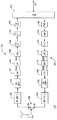
図1は、たとえばWLANシステムのアクセス・ポイント(AP)またはクライアント端末(CLT)として構成することができる、従来の技術の代表的なOFDMトランシーバ100のブロック図である。通常のWLANシステムは、バックボーン有線ネットワークへのアクセスを1つまたは複数の無線CLTに提供するAPを有する。トランシーバ100は、受信経路102および送信経路104を有し、これらは両方とも、一端において媒体アクセス制御装置(MAC)106に結合され、他端においてスイッチ126を介してアンテナ124に結合される。動作モードに応じて、スイッチ126は、アンテナ124を送信経路104または受信経路102に接続する。
FIG. 1 is a block diagram of a
送信経路104において、MAC106を介して受信された情報ビットは、たたみ込みエンコーダ108によって符号化され、インタリーバ110によってインタリーブされる。次いで、インタリーブされたデータは、マッピング変換器112を使用して、バイナリ・フォーマットからQAM値などに変換される。首尾一貫した受信を容易にするために、4つの指針値が、52のQAM値を有するOFDM記号を形成するように、各48のデータ値に追加される。QAM値は、シリアル・パラレル(S/P)変換器114において逆多重化され、逆高速フーリエ変換(IFFT)要素116を使用して52のトーンに変調される。次いで、このトーンは、並列直列(P/S)変換器118において組み合わされる。通信チャネルにおける多重経路遅延拡散(信号分散)による記号間干渉を低減するために、循環接頭辞(CP)が、CP加算器120において追加される。結果として得られるOFDM記号は、無線周波数(RF)送信器122に加えられ、そこで、アナログ信号に変換され、5GHz帯に上方変換され、アンテナ124を経て送信される。
In the
受信経路102は、送信経路104の逆動作ならびに追加のトレーニング機能を実施するように設計される。具体的には、RF信号が、RF受信器128によってアンテナ125を経て受信される。RF受信器は、まず、各OFDMデータ・パケットのプリアンブルにある特別なトレーニング記号を使用して、周波数のオフセットおよび記号のタイミングを推定する。受信器128は、受信RF信号をOFDM記号に分割し、次いで、この記号は、周波数下方シフトされ、デジタル化される。CP除去回路130が、各記号から循環接頭辞を取り除き、その結果をS/P変換器132に加える。次いで、高速フーリエ変換(FFT)要素134が、52のトーンに対応するQAM値を回復する。トレーニング記号およびパイロット・トーンを使用して、通信チャネル応答ならびに位相ドリフトを補正する。次いで、回復されたQAM値を、P/S変換器136、デマッピング変換器138、デインタリーバ140をそれぞれ使用して、多重化、デマッピング、デインタリーブし、対応するバイナリ・データを回復する。情報ビットは、たたみ込み(たとえばビタビ)デコーダ142においてバイナリ・データから復号され、次いでMAC106を介してトランシーバ100から出力される。
The receive
トランシーバ100に付随する1つの問題は、家庭、事務所、および/または生産設備など、比較的高度に散乱する環境における動作の確実性に関する。具体的には、高速送信/受信(たとえば20Mbit/sを超える速度における)は、通信チャネルの品質に非常に敏感である。さらに、そのような高速送信/受信を意図した5GHz帯のRF信号は、たとえば2.4GHz帯の場合よりも高い伝播損失を受ける。その結果、高速での動作は、比較的短距離に限定される可能性がある。その距離外では、より低いフォールバック速度(たとえば6Mbit/s)を使用しなければならない可能性がある。これにより、情報のスループットが制限され、たとえば、トランシーバ100をアクセス・ポイントとして使用するWLANシステムを、潜在的な能力の一部で動作させる可能性がある。
One problem with
従来の技術の問題は、本発明の原理に従って、OFDMトランシーバのチャネル推定方法によって対処される。OFDMトランシーバは、受信OFDMパケットのプリアンブルを処理することによって、通信チャネルのチャネル状態情報(CSI)を導出するように構成される。受信パケットは、たとえば、非送信請求データ・パケット、または肯定応答パケットなどの送信請求サービス・パケットとすることができる。次いで、導出されたCSI情報を適用して、通信チャネル上で送信する重み付きOFDMパケットを生成することができる。その結果、このOFDMトランシーバと他の(たとえば単一アンテナの)OFDMトランシーバとの間に、改善された有効な通信チャネルを確立することが可能である。本発明のチャネル推定方法は、WLANシステムのアクセス・ポイント(AP)またはクライアント端末(CLT)において実施することが可能である。いずれの場合でも、改善された通信チャネルを使用して、たとえば、選択した送信ビット・レートに対応する距離を拡大する、および/またはAPとCLTとの間の送信ビット・レートを増大させることができる。さらに、または別法として、改善された通信チャネルを使用して、発生するRF電力を低減し、したがって電力消費を低減することができる。 The problems of the prior art are addressed in accordance with the principles of the present invention by a channel estimation method for an OFDM transceiver. The OFDM transceiver is configured to derive channel state information (CSI) for the communication channel by processing a preamble of the received OFDM packet. The received packet may be, for example, a solicited service packet such as an unsolicited data packet or an acknowledgment packet. The derived CSI information can then be applied to generate a weighted OFDM packet to transmit on the communication channel. As a result, it is possible to establish an improved effective communication channel between this OFDM transceiver and another (eg, single antenna) OFDM transceiver. The channel estimation method of the present invention can be implemented in an access point (AP) or a client terminal (CLT) of a WLAN system. In any case, using the improved communication channel, for example, increasing the distance corresponding to the selected transmission bit rate and / or increasing the transmission bit rate between the AP and the CLT it can. Additionally or alternatively, the improved communication channel can be used to reduce the generated RF power and thus reduce power consumption.
一実施形態によれば、本発明は、WLANシステムの信号処理の方法であり、本方法は、WLANシステムの第1ノードの第1アンテナおよび第2アンテナにおいてWLANシステムの第2ノードから送信された入信号を受信すること、入信号に基づいて、第1アンテナおよび第2アンテナにそれぞれ対応する第1サブチャネルおよび第2サブチャネルの減衰情報を決定すること、各トーンについて相対減衰がより低いサブチャネルにほぼすべてのRF電力が加えられる複数のトーンに基づく多搬送波変調方式を使用して、第1アンテナおよび第2アンテナから第2ノードに送信する出信号を生成することを備える。 According to one embodiment, the present invention is a method of signal processing in a WLAN system, wherein the method is transmitted from a second node of the WLAN system at a first antenna and a second antenna of a first node of the WLAN system. Receiving an incoming signal; determining attenuation information for a first sub-channel and a second sub-channel corresponding to the first antenna and the second antenna, respectively, based on the incoming signal; Generating an outgoing signal to transmit from the first antenna and the second antenna to the second node using a multi-carrier modulation scheme based on a plurality of tones in which substantially all of the RF power is applied to the channel.
他の実施形態によれば、本発明は、WLANシステムにおける第1ノードの装置であって、本装置は、(i)第1ノードの第2アンテナおよび第2アンテナにおいて、WLANシステムの第2ノードから送信された入信号を受信し、(ii)入信号に基づいて、第1アンテナおよび第2アンテナにそれぞれ対応する第1サブチャネルおよび第2サブチャネルの減衰情報を決定するように適合された受信経路と、各トーンについて相対減衰がより低いサブチャネルにほぼすべてのRF電力が加えられる複数のトーンに基づく多搬送波変調方式を使用して、第1アンテナおよび第2アンテナから第2ノードに送信する出信号を生成するように適合された送信経路とを備える。
本発明の他の態様、特徴、および利点は、以下の詳細な記述と、添付の特許請求の範囲と、付随する図とからより完全に明らかになるであろう。
According to another embodiment, the invention is a device of a first node in a WLAN system, the device comprising: (i) a second node of the WLAN system at a second antenna and a second antenna of the first node. And (ii) determining attenuation information of the first sub-channel and the second sub-channel corresponding to the first antenna and the second antenna, respectively, based on the incoming signal. Transmit from a first antenna and a second antenna to a second node using a receive path and a multi-carrier modulation scheme based on multiple tones where substantially all RF power is applied to a sub-channel with lower relative attenuation for each tone A transmission path adapted to generate an outgoing signal.
Other aspects, features, and advantages of the invention will be more fully apparent from the following detailed description, the appended claims, and the accompanying drawings.
本明細書における「一実施形態」または「実施形態」という言及は、その実施形態に関連して記述される特定の特徴、構造、または特性を本発明の少なくとも1つの実施形態において含むことができることを意味する。本明細書の様々な箇所の「一実施形態における」という句の出現は、必ずしも、すべて同じ実施形態を指すとは限らず、また他の実施形態と互いに排他的な別々の実施形態または代替実施形態でもない。 Reference herein to "one embodiment" or "an embodiment" may include a particular feature, structure, or characteristic described in connection with that embodiment in at least one embodiment of the invention. Means The appearances of the phrase "in one embodiment" in various places in this specification are not necessarily all referring to the same embodiment, and are separate or alternative implementations that are mutually exclusive with the other embodiments. Not a form.
多ブランチ・トランシーバ
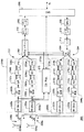
図2は、本発明の一実施形態によるOFDMトランシーバ200のブロック図を示す。実施態様に応じて、トランシーバ200は、1つのAPおよび1つまたは複数の無線CLTを有するコンテンション・ベースWLANシステムまたは計画型TDDベースWLANシステムに展開することができる。本発明の好ましいWLAN構成では、APは、トランシーバ200を有し、各CLTは、単一アンテナ・トランシーバ(たとえば図1のトランシーバ100)を有する。本発明の代替WLAN構成では、APは、単一アンテナ・トランシーバを有し、少なくとも1つのCLTは、トランシーバ200を有する。
Multi-Branch Transceiver FIG. 2 shows a block diagram of an
図1のトランシーバ100と同様に、トランシーバ200は、受信経路202および送信経路204を有し、両方とも、一端においてMAC206に結合される。しかし、トランシーバ100とは対照的に、トランシーバ200の各経路202および204は、2つのブランチ、すなわち2つの受信器ブランチ246a〜bおよび2つの送信器ブランチ244a〜bをそれぞれ有する。受信経路202のブランチ246a〜bのそれぞれは、RF受信器228、CP除去回路230、S/P変換器232、FFT要素234と、および/またはP/S変換器236を含み、これらは、受信経路102(図1)の同様に符号を付けられた(すなわち最後の2つの数字が同じである)要素と同様である。同様に、送信経路204のブランチ244a〜bのそれぞれは、S/P変換器214、IFFT要素216、P/S変換器218、CP加算器220、およびRF送信器222を含み、これらは、送信経路104(図1)の同様に名称付けされた要素と同様である。ブランチ244aおよび246aは、スイッチ226aを介して第1アンテナ224aに結合され、ブランチ244bおよび246bは、スイッチ226bを介して第2アンテナ224bに結合される。アンテナ224a〜bは、空間的に離れており、スイッチ226a〜bの状態に応じて、RF信号の送信または受信を送信器ブランチ244a〜bおよび受信器ブランチ246a〜bにそれぞれ提供する。代替実施形態では、本発明のトランシーバは、3つ以上のアンテナに選択的に結合された3つ以上のブランチをそれぞれが有する受信経路および送信経路を有することが可能である。
Like
ブランチ244a〜bの他に、送信経路204は、たたみ込みエンコーダ208と、インタリーバ210と、マッピング変換器212と、ブランチ重み付けおよび分割回路250とを含む。ブランチ246a〜bの他に、受信経路202は、ブランチ処理およびデマッピング回路260と、デインタリーバ240と、たたみ込み(ビタビなど)デコーダ242とを含む。以下でより詳細に記述する回路250および260を除いて、経路202および204の他の上記に列挙した要素は、経路102および104(図1)の同様に名称付けされた要素と同様である。
In addition to
一実施形態では、回路250および260は、RF受信器228a〜bおよびMAC206から信号を受信するために結合されたチャネル状態情報(CSI)プロセッサ270によって制御される。プロセッサ270は、アンテナ224a〜bに対応する通信サブチャネルのCSI情報を導出および記憶するように構成される。本明細書で使用する際に、「サブチャネル」という用語は、アンテナ224a〜bの1つと他のトランシーバのアンテナとの間の信号伝播を支持する無線媒体を指す。具体的には、一構成では、アンテナ224a〜bに関連付けられた2つのサブチャネルのCSIセットは、各サブチャネルについて、そのサブチャネルを介した各トーンの伝送に関連する減衰および/または位相シフトを含むことが可能である。異なる構成では、各トーンについて、CSIセットは、相対減衰がより低いサブチャネルを示す数(たとえば0または1)を含むことが可能である。一実施形態では、プロセッサ270は、現行CSIセットに基づいて生成された信号272a〜bを介して回路250および260を制御する。一構成では、プロセッサ270は、新しいOFDMパケットがトランシーバ200に到達するたびに、CSIセットを更新する。
In one embodiment,
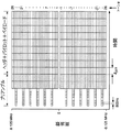
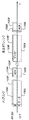
図3A〜Bは、規格802.11によるOFDMパケットの構造を示す。より具体的には、図3Aは、1つのトーン(たとえばトーン数20)に対応するOFDMパケットの一部の時間構造を示し、図3Bは、OFDMパケット全体の時間周波数構造を示す。各OFDMパケットは、ヘッダおよびデータ・ペイロード部分が続くプリアンブルを有する。プリアンブルは、それぞれが8μsの長さの2つの部分を有し、ヘッダは、長さが4μsであり、データ・ペイロード部分の長さは、可変である。トーン数−21、−7、7、および21は、4つのパイロット・トーンであり、図3Bのすべてのマーク付けされた(埋められた)矩形は、既知のトレーニング値に対応する。 3A and 3B show the structure of an OFDM packet according to the standard 802.11. More specifically, FIG. 3A shows a time structure of a part of an OFDM packet corresponding to one tone (for example, 20 tones), and FIG. 3B shows a time frequency structure of the entire OFDM packet. Each OFDM packet has a preamble followed by a header and a data payload portion. The preamble has two portions, each 8 μs in length, the header is 4 μs in length, and the length of the data payload portion is variable. Tone numbers -21, -7, 7, and 21 are four pilot tones, and all marked (filled) rectangles in FIG. 3B correspond to known training values.
プリアンブルの第1部分は、800nsの継続時間を有するトレーニング記号の10の反復(図3Aではt1からt10まで名称付けされている)を有する。この部分は、図3Bに示すように数が4の整数倍(すなわち、トーン数−24、−20、−16、−12、−8、−4、4、8、12、16、20、および24)であるトーンのサブセットを使用して送信され、自動利得制御(AGC)および粗周波数オフセットに使用される。プリアンブルの第2部分は、2つの正規のOFDM記号スロットを占有する長いトレーニング記号(図3AではT1と名称付けされている)を有する。プリアンブルのこの部分は、52のトーンをすべて使用して送信され(図3B)、タイミング、微細周波数オフセット、およびチャネル推定に使用される。プリアンブルには、ヘッダが続き、ヘッダは、図3Aに示すように、1つの正規のOFDM記号スロットを占有する。ヘッダは、符号化速度、変調のタイプ、およびパケット長に関する情報を含み、ヘッダには、データ・ペイロード部分が続く。 The first part of the preamble has 10 repetitions of the training symbol (named from t1 to t10 in FIG. 3A) having a duration of 800 ns. This portion is divided into integer multiples of four as shown in FIG. 24) is transmitted using a subset of tones and is used for automatic gain control (AGC) and coarse frequency offset. The second part of the preamble has a long training symbol (labeled T1 in FIG. 3A) that occupies two regular OFDM symbol slots. This portion of the preamble is transmitted using all 52 tones (FIG. 3B) and is used for timing, fine frequency offset, and channel estimation. The preamble is followed by a header, which occupies one regular OFDM symbol slot, as shown in FIG. 3A. The header contains information about the coding rate, the type of modulation, and the packet length, followed by the data payload portion.
一実施形態では、トランシーバ200のプロセッサ270は、プリアンブルの第2部分(図3AのT1)を処理することによって、CSI情報を獲得する。この部分において送信されるすべての値は、既知のトレーニング値であるので、それぞれのアンテナに対応する通信サブチャネルにおける52のトーンのそれぞれの伝播に対応する減衰および位相シフトを獲得することができる。一実施形態では、プロセッサ270は、複素数値Ca,b(n)の形態でCSI情報を導出および記憶する。各複素数値は、振幅および位相を有し、指標aおよびbはアンテナを指し、nはトーン数であり、各振幅|Ca,b(n)|および位相φa,b(n)は、それぞれの通信サブチャネルにおけるn番目のトーンの減衰および位相シフトにそれぞれ対応する。
In one embodiment,
一構成では、トランシーバ200は、WLANシステムのAPとして動作する。トランシーバ200の他に、WLANシステムは、1つまたは複数の単一アンテナCLTを含む。CLTは、規格802.11aに記述されているように、無線媒体を共有し、それにより、一度に1つのCLTのみが、AP200にデータを送信し(アップリンク)、またはAP200からデータを受信する(ダウンリンク)。一実施形態では、プロセッサ270は、MAC206によって提供されたCLT識別を使用して、各異なるCLTについて異なるCSIセットを導出および記憶する。
In one configuration,
受信動作
このセクションは、本発明の実施形態によるトランシーバ200の受信動作に関する。トランシーバ200が、WLANシステムのAPとして構成された場合、受信動作は、アップリンク(UL)伝送に対応する。好ましい構成では、WLANシステムは、(i)トランシーバ200を有するAPと、(ii)それぞれが図1のトランシーバ100などの単一アンテナ・トランシーバを有する1つまたは複数のCLTとを含む。
Receive Operation This section relates to the receive operation of
UL伝送中、トランシーバ200は、2つのアンテナ224a〜bを介してCLTからRF信号を受信する。2つ以上のアンテナを使用することにより、(i)アレイ利得および(ii)空間多様性の効果のために、信号受信が改善される。「アレイ利得」という用語は、2つのアンテナが、単一アンテナに対応するエネルギー量の2倍を平均して獲得するということに関する。「空間多様性」という用語は、異なるアンテナでの信号受信が、異なる(相関のない)フェーディング効果を通常受けるということに関する。したがって、1つのサブチャネルに対応する信号が、深いフェードにある場合、第2サブチャネルに対応する信号が同様に深いフェードにある確率は、相対的に低い。その結果、獲得されたRF電力の時間的な揺らぎの大きさは低減され、これにより、APとCLTとの間により確実な有効通信チャネルが生成される。
During UL transmission,
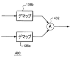
図4は、本発明の一実施形態によるトランシーバ200(図2)の回路260として使用することができる回路400を示す。すでに上記で指摘したように、回路260は、2つのアンテナ224a〜bに結合された2つの受信器ブランチ246a〜bの出力を処理する。図4の回路400は、2つのデマッピング変換器138a〜bを備え、各変換器は、対応する受信器ブランチ246に結合される。各変換器138は、対応するFFT要素234によって生成された周波数領域の同相(I)値および直角位相(Q)値に基づいて、各情報ビットについてソフト高信頼値を生成する。情報ビットに対応する2つのソフト値は、ソフト加算器402に加えられ、そこで、値は、その情報ビットについて新しいソフト高信頼値を生成するために、当技術分野において既知であるように最尤(ML)組み合わせされる。この新しいソフト高信頼値は、回路400から出力されて、図2のデインタリーバ240に加えられる。
FIG. 4 shows a
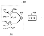
図5は、本発明の他の実施形態によるトランシーバ200の回路260(図2)として使用することができる回路500を示す。回路500は、I/Qプロセッサ502およびデマッピング変換器138を備える。各OFDMトーンについて、プロセッサ502は、I’/Q’と表記される新しいI/Q対を生成するために、FFT要素234aおよび234bによってそれぞれ生成された2つのI/Q対を処理する。次いで、I’/Q’対が1つのトーンから発せられたかのように、I’/Q’対を変換器138によって処理する。一実施形態では、プロセッサ502は、当技術分野において一般に最大比率組合わせ(MRC)と呼ばれる技法を実施する。
FIG. 5 shows a
一実施形態では、プロセッサ502は、I/Q対を以下のように処理する。各トーンについて、以下の式により複素数値Z(n)を計算する。
Z(n)=Wa(n)(Ia(n)+iQa(n))+Wb(n)(Ib(n)+iQb(n)) (1)
上式で、指標aおよびbはアンテナを指し、nはトーン数であり、Ia(n)/Qa(n)およびIb(n)/Qb(n)は、n番目のトーンに対応するI/Q対であり、それぞれブランチ246aおよび246bによってプロセッサ502に加えられ、Wa(n)およびWb(n)は、重み付け係数である。次いで、n番目のトーンに対応するI’/Q’対を以下のようにZ(n)から決定することができる。
I’(n)=ReZ(n) (2A)
Q’(n)=ImZ(n) (2B)
In one embodiment,
Z (n) = W a ( n) (I a (n) + iQ a (n)) + W b (n) (I b (n) + iQ b (n)) (1)
Where the indices a and b refer to the antenna, n is the number of tones, and I a (n) / Q a (n) and I b (n) / Q b (n) are the n th tones a corresponding I / Q pairs are added to the
I ′ (n) = ReZ (n) (2A)
Q ′ (n) = ImZ (n) (2B)
一実施態様では、重み付け係数は、以下のようにCSIセットから導出される。

一実施形態では、式(3)による重み付け係数Wa,b(n)の導出は、プロセッサ270において実施される。他の実施形態では、信号272a〜bは、Ca,b(n)の値をプロセッサ260に提供し、そこで、式(3)に対応する処理が実施され、重み付け係数Wa,b(n)が生成される。異なる実施形態では、式(3)に対応する処理とは異なる処理をプロセッサ260またはプロセッサ270において実施して、重み付け係数を生成することが可能である。
In one embodiment, the derivation of the weighting coefficients Wa , b (n) according to equation (3) is performed in the
一実施形態では、プロセッサ502は、2つの複素数乗算器504a〜bおよび複素数加算器508を含む。各乗算器504は、2つの入力を受信する。たとえば、乗算器504aは、受信器ブランチ246aから信号506aを受信し、CSIプロセッサ270から信号272aを受信する(図2)。同様に、乗算器504bは、受信器ブランチ246bから信号506bを受信し、CSIプロセッサ270から信号272bを受信する。信号506aおよび506bは、それぞれ、Ia(n)/Qa(n)対およびIb(n)/Qb(n)対を提供し、信号272aおよび272bは、それぞれ、重み付け係数Wa(n)およびWb(n)を提供する。各乗算器504は、複素数乗算を実施して、各トーンについて重み付きI/Q対を生成する。その結果は、加算器508に加えられ、そこで、各トーンについて、2つの重み付きI/Q対を組み合わせて、I’/Q’対を生成する。次いで、この対は、変換器138に加えられて、変換器138によって処理され、その出力は、図2のデインタリーバ240に加えられる。
In one embodiment,
本発明者自身の研究は、上記で記述した実施形態による2つのアンテナを介して信号を受信して、信号を処理するトランシーバ200が、単一アンテナ・トランシーバ(たとえばトランシーバ100)と比較して信号対雑音比(SNR)を、約1%と10%との間のパケット誤り率(PER)について約5から8dB改善することを実証した。この改善を使用して、たとえば、選択した送信ビット・レートに対応する距離を拡大する、および/またはたとえばAPとCLTとの間の送信ビット・レートを増大させることができる。さらに、または代替として、この改善を使用して、発生するRF電力を低減することが可能である。そのような電力の低減は、無線CLTの電池寿命を延長するのに役立つ可能性がある。
The inventor's own work has shown that
送信動作
このセクションは、トランシーバ200の送信動作に関する。トランシーバ200が、WLANシステムのAPとして構成された場合、送信動作は、ダウンリンク(DL)伝送に対応する。
Transmit Operation This section relates to the transmit operation of
DL伝送中、APトランシーバ200は、2つのアンテナ224a〜bを介してRF信号をCLTに送信する。一実施形態では、トランシーバ200は、各トーンに対応する信号を処理することによって、2つのアンテナ上で送信する重み付きOFDMパケットを生成する。処理は、各トーンについて、(i)トーンに対応するRF電力をアンテナ間において分割すること、(ii)異なる送信器ブランチにおいて、異なる位相シフトをトーンに対応する信号に加えることを含むことが可能である。そのような処理は、個々のトーンの強い減衰(フェーディング)など、通信チャネルの望ましくない影響を大きく低減する。たとえば、各トーンについて、異なるアンテナを介して送信された信号は、単一アンテナCLTなどの宛先受信器にほぼ同相で到着して、強め合って干渉するように位相シフトされる。その結果、改善された有効な通信チャネルが、APとCLTとの間に確立される。
During DL transmission,
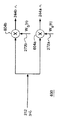
図6は、本発明の一実施形態によるトランシーバ200の回路250(図2)として使用することができる回路600を示す。回路600は、2つのアンテナ224a〜b上で送信されたRF電力の分配を制御するように設計される。各OFDMトーンについて、回路600は、マッピング変換器212によって生成されたI/Q対を処理して、送信器ブランチあたり1つの対で、2つの重み付きIa,b/Qa,b対を生成する。次いで、各重み付き対は、対応する送信器ブランチ244に加えられ、それぞれのアンテナ226を介して対応するRF信号を送信するために、独立して処理される。
FIG. 6 shows a
一実施形態では、回路600は、以下のようにI/Q対を処理する。
Ia,b(n)=Re{Wa,b(n)(I(n)+iQ(n))} (4A)
Qa,b(n)=Im{Wa,b(n)(I(n)+iQ(n))} (4B)
上式で、Ia(n)/Qa(n)およびIb(n)/Qb(n)は、n番目のトーンに対応する重み付きI/Q対であり、それぞれブランチ244aおよび244bに加えられる。Wa,b(n)は、重み付け係数である。
In one embodiment,
I a, b (n) = Re {W a, b (n) (I (n) + iQ (n))} (4A)
Q a, b (n) = Im {W a, b (n) (I (n) + iQ (n))} (4B)
Where I a (n) / Q a (n) and I b (n) / Q b (n) are the weighted I / Q pairs corresponding to the nth tone,
一実施形態では、回路600は、回路500の乗算器504a〜b(図5)と同様の2つの複素数乗算器604a〜bを含む。各乗算器604は、2つの入力を受信し、第1は、変換器212の出力のコピーであり、第2は、CSIプロセッサ(図2)からの対応する信号272である。各乗算器604は、複素数の乗算を実施し、たとえば式4A〜Bにより、各トーンについて重み付きI/Q対を生成する。次いで、この対は、対応する送信器ブランチ244に加えられる。
In one embodiment,
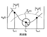
図7A〜Bは、本発明の一実施形態によるトランシーバ200において実施することができる分割方式を示す。これ以後、この方式を最大比率送信(MRT)方式と呼ぶ。より具体的には、図7Aおよび7Bは、トランシーバ200のブランチ244aおよび244bにそれぞれ対応する代表的なOFDMトーンを示す。Ha,b(f)と名称付けされた2つの曲線は、対応する通信サブチャネルの空間特性を表す。関数Ha,b(f)は、周波数fの複素関数であり、振幅|Ha,b(f)|および下記のように表わされる位相
Ca,b(n)=Ha,b(fn) (5)
上式で、fnは、n番目のトーンに対応する周波数である。パケットのプリアンブルを使用してCa,b(n)を導出することができる受信動作とは対照的に、送信動作では、Ca,b(n)の値は、直接には利用可能でなく、たとえば次のセクションにおいてより詳細に記述するチャネル推定方式の1つを使用して、別々に獲得する必要がある。
7A-B illustrate a partitioning scheme that can be implemented in
C a, b (n) = H a, b (f n ) (5)
Where f n is the frequency corresponding to the nth tone. Using a preamble of the packet C a, in contrast to the reception operation can be derived b (n), the transmission operation, the value of C a, b (n) is directly is not available , For example, using one of the channel estimation schemes described in more detail in the next section.
一実施態様では、MRT方式において使用される重み付け係数Wa,b(n)は、式(3)により計算される。したがって、各トーンについて、各通信サブチャネルは、送信係数Ta,b|Ha,b(fn)|に比例するRFエネルギーの部分を受信する。この場合、サブチャネルにおけるトーンの減衰は、1/Ha,b(fn)に比例する。たとえば、図7A〜Bに示したサブチャネルの状態では|Ha(fn)|>|Hb(fn)|なので、アンテナ224aは、アンテナ224bより、n番目のトーンに対応するRFエネルギーを多く送信する。 In one embodiment, the weighting factors W a, b (n) used in the MRT scheme are calculated according to equation (3). Accordingly, for each tone, each communication sub-channel, transmits the coefficient T a, b | H a, b (f n) | receives a portion of the proportional RF energy. In this case, the attenuation of the tone in the sub-channel is proportional to 1 / H a, b (f n). For example, in the state of the sub-channel shown in FIGS. 7A and 7B, | H a (f n ) |> | H b (f n ) | Send a lot.
RF電力分配の他に、各トーンについて、MRT方式は、それぞれの通信サブチャネルにおいて獲得される位相シフトを事前補償する。たとえば、n番目のトーンについて、式(3)によって与えられた重み付け係数Wa,b(n)を適用することにより、図7A〜Bのそれぞれの位相サークル図によって例示的に示すように、送信前に−φa,b(n)の位相シフトが分与される。この位相シフトは、送信後に、通信サブチャネルの位相シフトによってほぼ消去される。その結果、各トーンについて、異なるアンテナを介して送信された信号は、CLTなどの宛先受信器にほぼ同相で到着して、強め合う干渉をする。 In addition to RF power distribution, for each tone, the MRT scheme pre-compensates for the phase shift obtained in the respective communication subchannel. For example, for the nth tone, by applying the weighting factors Wa , b (n) given by equation (3), the transmission is performed, as exemplarily shown by the respective phase circle diagrams of FIGS. Previously, a phase shift of -φ a, b (n) is provided. This phase shift is almost canceled after transmission by the phase shift of the communication subchannel. As a result, for each tone, signals transmitted via different antennas arrive at a destination receiver, such as a CLT, almost in-phase, causing constructive interference.
図8A〜Bは、本発明の他の実施形態によるトランシーバ200において実施することができる分割方式を示す。これ以後、この方式を等価利得送信(EGT)方式と呼ぶ。図8A〜Bは、図7A〜Bと同様であり、それぞれブランチ244aおよび244bに対応するOFDMトーンを表す。
8A-B illustrate a partitioning scheme that can be implemented in
一実施態様では、EGT方式において使用される重み付け係数Wa,b(n)は、以下のように式(6)により計算される。
図9A〜Bは、本発明の他の実施形態によるトランシーバ200において実施することができる分割方式を示す。これ以後、この方式をサブチャネル選択送信(SST)方式と呼ぶ。図9A〜Bは、図7A〜Bおよび図8A〜Bと同様であり、ブランチ244a(図9A)および244b(図9b)に対応するOFDMトーンを表す。
9A-B illustrate a partitioning scheme that can be implemented in
一実施態様では、SST方式において使用される各重み付け係数Wa,b(n)は、1または0であり、たとえば以下のように決定される。
Wa(n)=1およびWb(n)=0,|Ca(n)|≧|Cb(n)|の場合 (7A)
Wa(n)=0およびWb(n)=1,|Ca(n)|<|Cb(n)|の場合 (7B)
したがって、各トーンについて、最低の減衰を有する通信サブチャネルは、そのトーンに対応する全RF電力を受信する。たとえば、図9A〜Bに示すように、アンテナ224aは、n番目および(n+1)番目のトーンに対応するRF信号を送信し、一方、アンテナ224bは、(n−1)番目のトーンに対応するRF信号を送信する。MRT方式およびEGT方式とは対照的に、SST方式は、位相シフト事前補償を実施しない。しかし、各トーンに対応するRF電力が、唯一のサブチャネルに加えられ、それにより、宛先受信器における異なるサブチャネルからのRF信号の弱め合う干渉の問題に対処する。
In one embodiment, each weighting factor W a, b (n) used in the SST scheme is 1 or 0 and is determined, for example, as follows.
W a (n) = 1 and W b (n) = 0, | C a (n) | ≧ | C b (n) | of the case (7A)
When W a (n) = 0 and W b (n) = 1, | C a (n) | <| C b (n) | (7B)
Thus, for each tone, the communication sub-channel with the lowest attenuation receives the full RF power corresponding to that tone. For example, as shown in FIGS. 9A-B,
図10は、トランシーバ100など、6、18、および54Mbit/sで動作するトランシーバ200の送信性能と、同様に動作する単一アンテナ・トランシーバの送信性能とを比較する。より具体的には、各トランシーバについて、パケット誤り率(PER)対SNR曲線が、100nsの特徴的な崩壊定数を有する代表的な通信チャネルについて示されている。トランシーバ200では、MRT方式、EGT方式、およびSST方式に対応するPER対SNR曲線が、各ビット・レートについて示されている。図10からわかるように、PER=5%(水平点線によって示す)において、トランシーバ200は、3つのビット・レートのそれぞれについて、トランシーバ100に対し、約5.5dBと7.5dBの間の性能の改善を実現する。すなわち、所与の送信電力レベルについて、トランシーバ200は、トランシーバ100より長い距離にわたって送信することができ、かつ依然として同じまたはより良好なPERを達成することができる。MRT方式は、最大の性能の改善を提供し、この場合、MRT方式とEGT方式およびSST方式とのSNRの差は、それぞれ、約0.5〜1.0dBおよび1.0〜1.5dBである。受信動作と同様に、これらの性能の改善を使用して、たとえば、選択した送信ビット・レートに対応する距離を拡大する、通信トランシーバ間の送信ビット・レートを増大させる、および/または電力消費を低減することができる。
FIG. 10 compares the transmission performance of
チャネル推定
上記で記述したように、トランシーバ200は、他のトランシーバから受信したアップリンク(UL)パケットからCSI情報を導出して、(1)それらの受信ULパケットの処理、および(2)他のトランシーバに再び送信されるその後のDLパケットの処理の両方に使用する。一般に、以下で記述するチャネル推定方法を、コンテンション・ベースWLANシステムおよび計画TDDベースWLANシステムの両方について実施することができる。しかし、適切であれば指摘するように、以下で考慮する通信のいくつかのシナリオは、コンテンション・ベースWLANシステムのみに特有である。
Channel Estimation As described above,
図11は、本発明の一実施形態による、特定の(単一アンテナ)CLTトランシーバからAPトランシーバ200において受信したULパケットを使用して、トランシーバ200からその特定のCLTに送信するその後のDLパケットを生成するために使用することが可能であるCSI情報を導出する方法を一般的に示す。
FIG. 11 illustrates the use of UL packets received at a
具体的には、UL伝送中、CLTは、パケット1102をAP200に送信し、このパケットは、アンテナ224aおよび224bを介してパケット1102’および1102”としてそれぞれ受信される。各パケット1102’および1102”のプリアンブル(図11ではPと名称付けされている)を使用して、プロセッサ270は、たとえば図2、4、および5の文脈において上記で記述したように、このUL伝送中に対応する通信サブチャネルの状態についてCSI情報を導出する。2つのサブチャネルのCSI情報は、トランシーバ200と特定のCLTとの間のチャネルについて現行のCSIセットを形成する。プロセッサ270は、現行CSILセットが生成された時間を追跡する。その後のDL伝送中、AP200は、アンテナ224aおよび224bを介して重み付きパケット1104’および1104”をそれぞれ送信し、これらのパケットは、パケット1104を生成するために、CLTにおいて重ね合わされる。2つのトランシーバ間のチャネルの特性は、時間の経過と共に変化するので、CSI情報の所与のセットの精度は、通常、その情報の年齢に依拠することになる(すなわち、CSI情報が導出された最近のULパケットの受信と、その後のDLパケットの送信との間の時間)。
Specifically, during UL transmission, the CLT sends a
図11に示すシナリオは、2つの異なる状況に対応すると考えられる。一方の状況では、CLTは、トランシーバ200で前後に送信されているパケットの現行シーケンスを開始し、一方他の状況では、トランシーバ200は、現行通信シーケンスを開始する。前者の状況では、パケット1102は、通信シーケンスの第1パケットを表すと考えられ、パケット1104は、第2パケットを表すと考えられる。その場合、CSI情報は、比較的最近ULパケット1102から導出されており、DLパケット1104を正確に処理するために安全に使用することが可能である。
The scenario shown in FIG. 11 is considered to correspond to two different situations. In one situation, the CLT initiates a current sequence of packets being transmitted back and forth on
しかし、トランシーバ200が通信シーケンスを開始する他の状況では、パケット1104は、現行通信シーケンスの第1パケットを表し、一方パケット1102は、(たとえば、以前の通信シーケンス中に)同じCLTからトランシーバ200において受信した最後のパケットを表す可能性がある。その場合、ULパケット1102から導出されたCSI情報は、比較的古い可能性があり、したがって、DLパケット1104を処理するためにそのCSI情報を使用するかの問題に対処する必要がある。1つの可能な実施態様では、トランシーバ200は、CSIセットが指定時間期間内に生成された場合のみ、現行CSIセットをDLパケット1104の処理に使用する。CSIセットが古過ぎる場合、トランシーバ200は、「ブラインド」分割方式を適用する。この時間ベースの閾値処理を、CSIセットの年齢tpを現行閾値t0と比較することによって図11に示す。閾値t0は、たとえば通信チャネルの現行崩壊定数の関数として時間の経過と共に変化する可能性があり、または定数である可能性があることに留意されたい。
However, in other situations where the
現行CSIセットが古過ぎる場合、以下のブラインド分割方式の1つを使用することができる。すなわち(1)1つのアンテナのみを介して信号を送信する、(2)位相を調節せずに、アンテナ間でRF電力を分割する(たとえば50/50)、および(3)2つの信号コピーをそれぞれ異なるアンテナを介して送信し、第2コピーが、第1コピーより時間が遅れている。一実施形態では、時間遅延ブラインド分割方式を実施するために、送信器ブランチ244bは、CP加算器220bとRF送信器222bとの間に随意選択の遅延回路(図2には示さず)を含む。
If the current CSI set is too old, one of the following blind partitioning schemes can be used. (2) split RF power between antennas without adjusting phase (eg, 50/50); and (3) copy two signal copies. Each transmitted via a different antenna, the second copy being later in time than the first copy. In one embodiment, the
現行CSIセットを使用する場合、プロセッサ270は、たとえば上記で記述したMRT、EGT、およびSSTの分割方式の1つとすることができる選択した分割方式に基づいて決定された重み付け係数を適用するように、回路250を構成する。分割方式を適用することにより、APとCLTとの間に改善された有効な通信チャネルが生成されるので、たとえば通常のダウンリンク中よりも高いビット・レートを使用して、改良されたダウンリンクを実施することができる。改良ダウンリンクに対応するより高いビット・レートを、図11のアスタリスクによって例示的に示す。
When using the current CSI set,
図12〜15は、APトランシーバ200とCLT(単一アンテナ)トランシーバとの間における通信シーケンスの異なるシナリオについて、チャネル推定処理の適用を示す。
12-15 show the application of the channel estimation process for different scenarios of the communication sequence between the
より具体的には、図12A〜Bは、AP200と単一アンテナCLTとの間における2つの代表的な通信シーケンスを示し、各送信パケットを実線で示し、各受信パケットを点線で示す。図12A〜Bに示した両方の通信シーケンスとも、2つのデータ・パケットを有し、それぞれには肯定応答(ACK)が続く。肯定応答は、サービスOFDMパケットであり、これは、対応するデータ・パケットが宛先パーティによって受信された発信パーティを確認する。ACKパケットが受信されない場合、発信パーティは、データ・パケットを再送信する。
More specifically, FIGS. 12A-B show two representative communication sequences between the
図12Aの通信シーケンスは、DLデータ・パケットが続くULデータ・パケットを有し、それぞれには対応する肯定応答が続く。UL伝送中、AP200は、アンテナ224a〜bを介して、CLTによって送信されたデータ・パケット1202に対応するデータ・パケット1202’および1202”を受信する。応答して、AP200は、ACKパケット1204’および1204”を送信し、これらは、CLTによってACKパケット1204として受信される。AP200のプロセッサ270は、パケット1202’および1202”のプリアンブル(P)を使用してCSIセットを導出し、記憶する。CSIセットに基づいて、プロセッサ270は、たとえば先行セクションにおいて記述したように、選択した分割方式をその後のDL伝送の1つまたは複数に適用するように回路250を構成する。分割方式を適用することにより、APとCLTとの間に改善された有効な通信チャネルが得られる可能性が高いので、たとえばULパケット1202を送信するために使用したビット・レートより高いビット・レートを使用して、改良ダウンリングを実施することができる。
The communication sequence of FIG. 12A has UL data packets followed by DL data packets, each followed by a corresponding acknowledgment. During UL transmission,
改良ダウンリング中、AP200は、重み付きデータ・パケット1206’および1206”を生成して、アンテナ224a〜bを介して送信し、こられのパケットは、CLTによってデータ・パケット1206として受信される。パケット1206(’)(”)に対応するより高いビット・レートを図12Aのアスタリスクによって示す。CLTによるデータ・パケット1206の受信は、ACKパケット1208を介して肯定応答される。一構成では、重み付きデータ・パケット1206’および1206”を生成するために分割方式を適用することの他に、AP200は、重み付きACKパケット1204’および1204”を生成するためにその方式を適用するようにも構成することが可能である。
During the refined downlink, the
図12Bの通信シーケンスは、2つのDLデータ・パケットを有し、それぞれには対応する肯定応答が続く。第1DL伝送中、AP200は、重み付きデータ・パケット1212’および1212”を生成して、アンテナ224a〜bを介して送信し、これらのパケットは、CLTによってデータ・パケット1212として受信される。第1ダウンリングは、(a)たとえば図12Aの改良ダウンリンクと同様に、対応するCSIセットを使用して実施された改良ダウンリング、または(b)たとえば、CSIセットが利用可能でない場合、または満了した場合、ブラインド分割方式を使用する通常のダウンリングとすることが可能である。CLTによるデータ・パケット1212の受信は、ACKパケット1214を介して肯定応答される。AP200は、ACKパケット1214’および1214”として肯定応答を受信し、これらのパケットのプリアンブルを使用して、新しいCSIセットを導出する。新しいCSIセットは、たとえば以前に記憶されたCSIセットと交換するために、プロセッサ270に記憶される。次いで、図12Bに示す第2ダウンリンク中に、新しいCSIセットを使用する。図12Aのダウンリンクと同様に、図12Bのダウンリンクは、改良ダウンリンクである。
The communication sequence of FIG. 12B has two DL data packets, each followed by a corresponding acknowledgment. During the first DL transmission,
図12Bの第2ダウンリンク中、AP200は、重み付きデータ・パケット1216’および1216”を生成して、アンテナ224a〜b上で送信し、これらのパケットは、CLTによってデータ・パケット1216として受信される。データ・パケット1216’および1216”に対応し、かつアスタリスクによって示したビット・レートは、図12Bのパケット1212’および1212”に対応し、かつ「#」符号によって示したものとは異なる(好ましくはより高い)可能性がある。CLTによるデータ・パケット1216の受信は、ACKパケット1218を介して肯定応答される。
During the second downlink of FIG. 12B,
図12のシナリオでは、時間軸の断続によって示した比較的長い時間期間(時間遅れ)が、CSIセットの導出とその後の適用との間に経過する可能性がある。時間遅れは、たとえば、コンテンション・ベースWLANシステムの「公正なコンテンション」無線媒体共有機構による可能性がある。通常、図12のシナリオの最良の結果は、以下の条件が当てはまるときに生じる。すなわち、(A)無線媒体が、重度に輻輳していない、(B)通信チャネルが、強い時間変動を受けない、(C)APとCLTとの間の経路に隣接して、移動するRF波散乱物体が存在しない、(D)APおよびCLT自体が、運動していない。 In the scenario of FIG. 12, a relatively long time period (time delay), indicated by intermittent time axes, may elapse between the derivation of the CSI set and its subsequent application. The time delay may be, for example, due to the "fair contention" wireless medium sharing mechanism of the contention based WLAN system. Typically, the best results for the scenario of FIG. 12 occur when the following conditions are true: That is, (A) the wireless medium is not severely congested, (B) the communication channel is not subject to strong time variations, (C) the RF wave traveling adjacent to the path between the AP and the CLT. There are no scattering objects, (D) AP and CLT themselves are not moving.
図13〜15のシナリオでは、AP200は、CLTから能動的に送信請求されたパケットを使用して、CSI情報を導出する。送信請求されたULパケットは、対応するDLパケットを送信する直前の比較的短い時間間隔内に受信されるので、ULパケットを処理することによって導出されたCSIセットは、DL伝送中の通信チャネルの状態について比較的正確な推定を提供する。
In the scenarios of FIGS. 13-15,
図13のシナリオは、通信チャネルの確保と、CSI情報の獲得との両方のために、規格802.11において規定されたチャネル確保機構を使用することを示す。規格によれば、チャネル確保は、2つのサービスOFDMパケットを使用して実施される。第1サービス・パケットは、データ発信パーティによって送信され、送信要求(RTS)と呼ばれる。第2サービス・パケットは、利用可能であり、かつデータを受信する準備ができている宛先パーティからの肯定応答(送信可、CTS)である。 The scenario of FIG. 13 shows the use of the channel reservation mechanism specified in the standard 802.11 for both the reservation of the communication channel and the acquisition of CSI information. According to the standard, channel reservation is implemented using two service OFDM packets. The first service packet is sent by the data originating party and is called a request for transmission (RTS). The second service packet is an acknowledgment (clear to send, CTS) from the destination party that is available and ready to receive data.
図13は、AP200と単一アンテナCLTとの間で交換されるRTSパケットおよびCTSパケットを含んでいる代表的な通信シーケンスを示す。図12と同様に、各送信パケットを実線で示し、各受信パケットを点線で示す。図13の通信シーケンスは、AP200からの送信要求(RTSパケット1302’および1302”)で開始され、この送信要求は、CLTによってRTSパケット1302として受信される。RTSパケット1302’および1302”は、ブラインド分割方式を使用して送信されることが好ましい。応答して、CLTは、CTSパケット1304を送信し、このパケットは、パケット1304’および1304”としてアンテナ224a〜bを介してAP200によって受信される。AP200のプロセッサ270は、パケット1304’および1304”のプリアンブル(P)を使用してCSIセットを導出する。CSIセットに基づいて、プロセッサ270は、重み付きデータ・パケット1306’および1306”を生成して送信するために、選択した(MRT、EGT、またはSST)分割方式を適用するように回路250を構成し、これらのパケットは、CLTによってパケット1306として受信される。CLTによるパケット1306の受信は、ACKパケット1308を介して肯定応答される。
FIG. 13 shows a representative communication sequence including RTS and CTS packets exchanged between the
すでに上記で指摘したように、図12のシナリオでは、AP200は、CSI情報が導出された後、無線媒体にアクセスするために、他の端末と競合しなければならない可能性がある。対照的に、図13のシナリオでは、パケットのシーケンスは、規格により事前に確定される。具体的には、パケット1304と1306との間の時間間隔中に、他の端末が妨害する(パケットを送信する)ことは可能ではない。その結果、それらのパケット間の時間遅れは、比較的小さいはずである;パケット1304’および1304”の処理から導出されたCSIセットは、通信サブチャネルの状態の正確な推定を提供するはずである;図13のアスタリスクによって示すように、パケット1306’および1306”を送信するために、比較的高いビット・レートを使用する改良ダウンリンクを実施することができる。
As pointed out above, in the scenario of FIG. 12, after the CSI information is derived, the
図14のシナリオは、規格802.11において規定された断片モード、または規格HIPERILAN/2において規定された同様のモードの使用を示す。そのようなモード中、データ・シーケンスが、2つ以上のデータ・パケット間において分割(断片化)され、次いで、順次送信される。例示するように、図14は、2つの断片F0およびF1を送信する通信シーケンスを示す。 The scenario of FIG. 14 illustrates the use of the fragment mode specified in the standard 802.11, or a similar mode specified in the standard HIPERILAN / 2. During such a mode, the data sequence is split (fragmented) between two or more data packets and then transmitted sequentially. As an example, FIG. 14 shows a communication sequence for transmitting two fragments F0 and F1.
図14の通信シーケンスは、短い(ほぼ空であることが好ましい)データ断片F0を送信することで開始される。このデータ断片は、AP200によってパケット1402’および1402”を使用してアンテナ224a〜bを介して送信され、CLTによってパケット1402として受信される。パケット1402’および1402”は、ブラインド分割方式を使用して送信されることが好ましい。応答して、CLTは、ACKパケット1404を送信し、このパケットは、AP200によってパケット1404’および1404”として受信される。AP200のプロセッサ270は、パケット1404’および1404”のプリアンブル(P)を使用してCSIセットを導出し、このCSIセットに基づいて、データ断片F1を有する重み付きデータ・パケット1406’および1406”を生成し、送信するために、選択した(MRT、EGT、またはSST)分割方式を適用するように回路250を構成する。パケット1406’および1406”は、CLTによってパケット1406として受信され、ACKパケット1408を介して肯定応答される。
The communication sequence of FIG. 14 is started by transmitting a short (preferably almost empty) data fragment F0. This data fragment is transmitted by
図13のシナリオと同様に、図14のシナリオでは、パケットのシーケンスは、規格により事前に確定される。具体的には、他の端末は、パケット1404と1406との間の時間間隔中に妨害しない。その結果、図14のアスタリスクによって示すように、パケット1406’および1406”を送信するために、比較的高いビット・レートを使用する改良ダウンリンクを実施することができる。
As in the scenario of FIG. 13, in the scenario of FIG. 14, the sequence of packets is determined in advance by the standard. Specifically, other terminals do not disturb during the time interval between
図15のシナリオは、規格802.11において規定された点座標関数(PCF)モードの使用を示す。そのようなモード中、APは、コンテンションのない(CF)データ転送を提供するために、無線媒体へのアクセスを一時的に制御し、一方、「公正なコンテンション」無線媒体共有機構は、一時的に中断される。図15は、PCFモードに対応する代表的な通信シーケンスを示す図である。 The scenario of FIG. 15 illustrates the use of the Point Coordinate Function (PCF) mode specified in the standard 802.11. During such a mode, the AP temporarily controls access to the wireless medium to provide contention-free (CF) data transfer, while the "fair contention" wireless medium sharing mechanism Temporarily interrupted. FIG. 15 is a diagram showing a typical communication sequence corresponding to the PCF mode.
図15の通信シーケンスは、規格802.11において規定された2つのサービス・パケットで開始される。第1サービス・パケット(図15ではBEACと名称付けされている)は、WLANシステムのタイミングを確定し、かつ同期をすべてのCLTに提供するために、AP200によってブロードキャストされた周期的なビーコンである。ビーコンを使用して、ビーコンの後に開始されるCF期間を公表することもできる。第2サービス・パケット(図15ではCFポーリングと名称付けされている)は、CF期間中に送信する特定のCLTに対する許可である。CFポーリング・パケットに応答して、CLTは、ACKパケット1504を送信し、これは、AP200によってパケット1504’および1504”として受信される。AP200のプロセッサ270は、パケット1504’および1504”のプリアンブル(P)を使用してCSIセットを導出し、このCSIセットに基づいて、重み付きデータ・パケット1506’および1506”を生成し、送信するために、選択した(MRT、EGT、またはSST)分割方式を適用するように回路250を構成する。これらのデータ・パケットは、CLTによってパケット1506として受信される。CLTによるパケット1506の受信は、ACKパケット1508を介して肯定応答される。CF期間の終了は、AP200によって第3サービス・パケット(図15ではCF終了と名称付けされている)を介して公表される。BEAC、CFポーリング、およびCF終了のパケットは、ブラインド分割方式を使用して送信されることが好ましい。
The communication sequence of FIG. 15 starts with two service packets specified in the standard 802.11. The first service packet (named BEAC in FIG. 15) is a periodic beacon broadcast by the
図15のシナリオは、デフォルトによって、CF期間中に実施されるので、他の端末は、パケット1504と1506との間の時間間隔中に妨害することはできない。その結果、図13および14のシナリオと同様に、図15のアスタリスクによって示すように、パケット1506’および1506”を送信するために、比較的高いビット・レートを使用する改良ダウンリンクを実施することができる。
Since the scenario of FIG. 15 is implemented by default during the CF period, other terminals cannot interfere during the time interval between
図11〜15のシナリオは、(多ブランチ)トランシーバ200に関して記述されているが、それらの方式は、単一アンテナに結合された1つの受信器ブランチおよび1つの送信器ブランチを有するトランシーバに適用することも可能である。RF電力を様々なトーンにわたって効率的に分配し、および/または発生するRF電力全体を低減するためにCSI情報を使用するように、そのようなトランシーバを構成することができる。たとえば、所与のトーンについて、通信チャネルの信号減衰が比較的低くなるように決定された場合、トランシーバは、PERおよび/またはビット・レートを犠牲にせずに、そのトーンに対応するより少ないRF電力を発生することが可能である。同様に、異なるトーンの信号減衰が、比較的高い場合、トランシーバは、PERおよび/またはビット・レートを維持するために、そのトーンについてより多くのRF電力を発生することが可能である。全発生RF電力の正味の減少に対応して、トランシーバの電力消費が減少する。これは、たとえば電力が電池によって供給される携帯式装置では、重要である。その結果、所与の電池のサイズでは、電池動作時間を延長することができ、または代替として、より小さい電池を使用して、同じ時間期間トランシーバに供給することができる。
Although the scenarios of FIGS. 11-15 are described with respect to (multi-branch)
二重ブランチOFDMトランシーバに関して本発明を記述したが、受信経路および送信経路のそれぞれに3つ以上のブランチを有するOFDMトランシーバを同様の方式で実施することができる。異なる分割方式を適用して、重み付きOFDMパケットを生成することが可能である。様々なタイプの入OFDMパケットを使用して、通信サブチャネルに対応するCSI情報を導出することが可能である。WLANシステムのアクセス・ポイントに関して本発明のある実施形態を記述したが、それらの実施形態は、クライアント端末において実施することも可能である。 Although the invention has been described with reference to a dual branch OFDM transceiver, an OFDM transceiver having three or more branches in each of the receive and transmit paths can be implemented in a similar manner. Different division schemes can be applied to generate weighted OFDM packets. Various types of incoming OFDM packets can be used to derive CSI information corresponding to a communication subchannel. Although certain embodiments of the invention have been described with reference to access points in a WLAN system, those embodiments may also be implemented at a client terminal.
新しい入パケットが到着するたびに、CSIの導出が独立して実施されるように記述したが、代替実施形態では、以前のCSIセットと、新しいパケットから導出されたCSIセットとの両方に基づいて、新しいCSIセットを導出することができる。さらに、CSIの導出は、選択的に実施することが可能である。たとえば、新しい入パケットが受信されたとき、最近のCSIセットの年齢が、以前に記述された閾値t0とは異なる可能性がある指定閾値を超える場合、新しい入パケットを使用して、新しいCSIセットを導出する。しかし、最近のCSIセットの年齢が指定閾値より小さい場合、CSIの導出は実施されず、現行CSIセットが依然として使用され、それにより、CSI情報の導出に関連する全体的な処理のオーバーヘッドが潜在的に低減される。 Although it has been described that the derivation of CSI is performed independently each time a new incoming packet arrives, an alternative embodiment is based on both the old CSI set and the CSI set derived from the new packet. , A new CSI set can be derived. Further, the derivation of CSI can be selectively implemented. For example, when a new incoming packet is received, the age of the most recent CSI set using the case, the new incoming packets exceeds a specified threshold can be different from the threshold t 0 described previously, new CSI Derive a set. However, if the age of the recent CSI set is less than the specified threshold, no CSI derivation is performed and the current CSI set is still used, thereby potentially increasing the overall processing overhead associated with deriving CSI information. To be reduced.
例示的な実施形態に関して本発明を記述してきたが、本記述は、限定的に構築されることを意図していない。記述した実施形態ならびに本発明の他の実施形態の様々な修正は、本発明が関係する分野の技術者には明らかであり、以下の特許請求の範囲に表す本発明の原理および範囲内にあると見なされる。 Although the invention has been described with reference to illustrative embodiments, this description is not intended to be construed in a limiting sense. Various modifications of the described embodiment, as well as other embodiments of the invention, will be apparent to persons skilled in the art to which the invention pertains and are within the principles and scope of the invention as set forth in the following claims. Is considered.
以下の方法請求項における工程は、あるとすれば、対応する名称付けを有する特定の順序で列挙されているが、請求項の列挙が、それらの工程のいくつかまたはすべてを実施する特定の順序を例示しない限り、それらの工程は、必ずしも、その特定の順序で実施されることに限定されることを意図していない。 Although the steps in the following method claims are listed in a particular order, if any, with corresponding naming, the recitations of the claims imply a particular order of performing some or all of those steps. Are not intended to be necessarily limited to being performed in that particular order.
本発明は、単一集積回路上での可能な実施を含めて、回路ベースのプロセスとして実施することが可能である。当業者には明らかであるように、回路要素の様々な機構は、ソフトウエア・プログラムの処理工程として実施することも可能である。そのようなソフトウエアは、たとえば、デジタル信号プロセッサ、マイクロコントローラ、または汎用コンピュータにおいて使用することが可能である。 The invention can be implemented as a circuit-based process, including possible implementations on a single integrated circuit. As will be apparent to those skilled in the art, the various features of the circuit elements may be implemented as processing steps in a software program. Such software can be used, for example, in a digital signal processor, microcontroller, or general-purpose computer.
Claims (10)
前記WLANシステムの第1ノードの第1アンテナおよび第2アンテナにおいて、前記WLANシステムの第2ノードから送信された入信号を受信すること、
前記入信号に基づいて、前記第1アンテナおよび前記第2アンテナにそれぞれ対応する第1サブチャネルおよび第2サブチャネルの減衰情報を決定すること、および、
各トーンについて、相対減衰がより低いサブチャネルにほぼすべてのRF電力が加えられる複数のトーンに基づく多搬送波変調方式を使用して、前記第1アンテナおよび前記第2アンテナから前記第2ノードへ送信する出信号を生成することを含む方法。 A method for signal processing in a WLAN system, comprising:
Receiving, at a first antenna and a second antenna of a first node of the WLAN system, an incoming signal transmitted from a second node of the WLAN system;
Determining attenuation information of a first sub-channel and a second sub-channel corresponding to the first antenna and the second antenna, respectively, based on the incoming signal; and
For each tone, transmit from the first antenna and the second antenna to the second node using a multi-carrier modulation scheme based on a plurality of tones in which substantially all RF power is applied to a subchannel with lower relative attenuation. Generating an outgoing signal.
前記第1ノードが、前記WLANシステムのアクセス・ポイントであり、
前記第2ノードが、前記WLANシステムのクライアント端末である、請求項1に記載の発明。 The WLAN system is a contention-based WLAN system that complies with the IEEE 802.11 standard;
The first node is an access point of the WLAN system;
The invention according to claim 1, wherein the second node is a client terminal of the WLAN system.
前記減衰情報が古過ぎる場合、前記第1ノードが、前記減衰情報とは関係なく前記出信号を生成する、請求項1に記載の発明。 The first node characterizes the age of the attenuation information, and determines whether to use the attenuation information when generating the outgoing signal based on the age of the attenuation information;
The invention of claim 1, wherein the first node generates the outgoing signal regardless of the attenuation information if the attenuation information is too old.
(i)前記第1ノードの第1アンテナおよび第2アンテナにおいて、前記WLANシステムの第2ノードから送信された入信号を受信し、(ii)前記入信号に基づいて、前記第1アンテナおよび前記第2アンテナにそれぞれ対応する第1サブチャネルおよび第2サブチャネルの減衰情報を決定するように適合された受信経路と、
各トーンについて、相対減衰がより低い前記サブチャネルにほぼすべてのRF電力が加えられる複数のトーンに基づく多搬送波変調方式を使用して、前記第1アンテナおよび前記第2アンテナから前記第2ノードに送信する出信号を生成するように適合された送信経路とを備える装置。
A device of a first node of a WLAN system,
(I) receiving, at a first antenna and a second antenna of the first node, an incoming signal transmitted from a second node of the WLAN system, and (ii) based on the incoming signal, the first antenna and the second antenna. A receiving path adapted to determine attenuation information for the first and second sub-channels respectively corresponding to the second antenna;
From each of the first and second antennas to the second node using a multi-carrier modulation scheme based on a plurality of tones in which substantially all RF power is applied to the sub-channel with lower relative attenuation for each tone. A transmission path adapted to generate an outgoing signal to transmit.
Applications Claiming Priority (1)
| Application Number | Priority Date | Filing Date | Title |
|---|---|---|---|
| US10/354,601 US7400609B2 (en) | 2003-01-30 | 2003-01-30 | Partitioning scheme for an OFDM transceiver |
Related Child Applications (1)
| Application Number | Title | Priority Date | Filing Date |
|---|---|---|---|
| JP2010186773A Division JP2011015424A (en) | 2003-01-30 | 2010-08-24 | Channel estimation for ofdm transceiver |
Publications (2)
| Publication Number | Publication Date |
|---|---|
| JP2004236336A true JP2004236336A (en) | 2004-08-19 |
| JP2004236336A5 JP2004236336A5 (en) | 2007-03-01 |
Family
ID=32655553
Family Applications (2)
| Application Number | Title | Priority Date | Filing Date |
|---|---|---|---|
| JP2004023377A Withdrawn JP2004236336A (en) | 2003-01-30 | 2004-01-30 | Channel estimation for ofdm transceiver |
| JP2010186773A Pending JP2011015424A (en) | 2003-01-30 | 2010-08-24 | Channel estimation for ofdm transceiver |
Family Applications After (1)
| Application Number | Title | Priority Date | Filing Date |
|---|---|---|---|
| JP2010186773A Pending JP2011015424A (en) | 2003-01-30 | 2010-08-24 | Channel estimation for ofdm transceiver |
Country Status (3)
| Country | Link |
|---|---|
| US (1) | US7400609B2 (en) |
| EP (1) | EP1445907A3 (en) |
| JP (2) | JP2004236336A (en) |
Cited By (2)
| Publication number | Priority date | Publication date | Assignee | Title |
|---|---|---|---|---|
| JP2008125070A (en) * | 2006-11-10 | 2008-05-29 | Samsung Electronics Co Ltd | Method and apparatus for ofdm communication |
| JP2014060591A (en) * | 2012-09-18 | 2014-04-03 | Renesas Electronics Corp | Receiver and communication device and communication system |
Families Citing this family (39)
| Publication number | Priority date | Publication date | Assignee | Title |
|---|---|---|---|---|
| JP2002290246A (en) * | 2001-03-28 | 2002-10-04 | Hitachi Kokusai Electric Inc | Transmitter-receiver |
| US7359311B1 (en) * | 2003-04-18 | 2008-04-15 | Cisco Technology, Inc. | Decoding method and apparatus using channel state information for use in a wireless network receiver |
| US7835262B2 (en) * | 2003-05-14 | 2010-11-16 | Texas Instruments Incorporated | Multi-band OFDM communications system |
| WO2004112289A2 (en) * | 2003-05-14 | 2004-12-23 | Texas Instruments Incorporated | Multi-band-ofdm communications systems |
| US7515541B2 (en) * | 2003-08-08 | 2009-04-07 | Intel Corporation | Transmission of data with feedback to the transmitter in a wireless local area network or the like |
| US7593347B2 (en) * | 2003-12-29 | 2009-09-22 | Intel Corporation | Method and apparatus to exchange channel information |
| US8369790B2 (en) | 2003-12-30 | 2013-02-05 | Intel Corporation | Communication overhead reduction apparatus, systems, and methods |
| US7345989B2 (en) * | 2004-01-12 | 2008-03-18 | Intel Corporation | Adaptive channelization scheme for high throughput multicarrier systems |
| US7665008B2 (en) * | 2004-01-12 | 2010-02-16 | Intel Corporation | Method and apparatus for implementing a low density parity check code in a wireless system |
| US20060025079A1 (en) * | 2004-08-02 | 2006-02-02 | Ilan Sutskover | Channel estimation for a wireless communication system |
| WO2006016858A1 (en) * | 2004-08-13 | 2006-02-16 | Agency For Science, Technology And Research | Transmitter, method for generating a plurality of long preambles and communication device |
| US7961828B2 (en) * | 2004-10-06 | 2011-06-14 | Motorola Mobility, Inc. | Sync bursts frequency offset compensation |
| KR100677568B1 (en) | 2005-02-07 | 2007-02-02 | 삼성전자주식회사 | Method for determining transmission rate of control response frame for the data reception in the wireless local network |
| CA2593462C (en) * | 2005-02-07 | 2014-08-26 | Samsung Electronics Co., Ltd. | Method of determining transmission rate of control response frame for acknowledging data receipt in wireless lan |
| US7924943B2 (en) * | 2005-02-07 | 2011-04-12 | Broadcom Corporation | Method and system for optional closed loop mechanism with adaptive modulations for multiple input multiple output (MIMO) wireless local area network (WLAN) system |
| US7876806B2 (en) * | 2005-03-24 | 2011-01-25 | Interdigital Technology Corporation | Orthogonal frequency division multiplexing-code division multiple access system |
| US7406327B2 (en) * | 2005-06-09 | 2008-07-29 | Harris Corporation | System that adapts power for minimizing the total amount of transmitted power within a wireless communications network and related method |
| US7894818B2 (en) * | 2005-06-15 | 2011-02-22 | Samsung Electronics Co., Ltd. | Apparatus and method for multiplexing broadcast and unicast traffic in a multi-carrier wireless network |
| US20070002724A1 (en) * | 2005-06-15 | 2007-01-04 | Samsung Electronics Co., Ltd. | Apparatus and method for broadcast superposition and cancellation in a multi-carrier wireless network |
| US8489133B2 (en) * | 2006-06-09 | 2013-07-16 | Nec Corporation | Communication system, transmission device, reception device, and synchronization method |
| US7966427B2 (en) * | 2006-09-29 | 2011-06-21 | Rockwell Automation Technologies, Inc. | Proxy object configuration of industrial component |
| US7813371B2 (en) * | 2007-03-21 | 2010-10-12 | Kapsch Trafficcom Ag | System and method for short range communication using adaptive channel intervals |
| US7792217B2 (en) * | 2007-03-30 | 2010-09-07 | Olympus Corporation | Method and system for channel estimation |
| US8422483B2 (en) * | 2007-03-30 | 2013-04-16 | Olympus Corporation | Method and system for channel estimation in burst mode |
| EP2071796B1 (en) * | 2007-12-12 | 2010-03-24 | Lg Electronics Inc. | Apparatus for transmitting and receiving a signal and method of transmitting and receiving a signal |
| US9154290B2 (en) * | 2007-12-12 | 2015-10-06 | Lg Electronics Inc. | Apparatus for transmitting and receiving a signal and method of transmitting and receiving a signal |
| ATE462257T1 (en) * | 2007-12-12 | 2010-04-15 | Lg Electronics Inc | DEVICE FOR SENDING AND RECEIVING A SIGNAL AND METHOD FOR SENDING AND RECEIVING A SIGNAL |
| KR101164117B1 (en) * | 2009-09-04 | 2012-07-12 | 엘지전자 주식회사 | Method of controlling a monitoring operation of a physical downlink channel in wireless communication system |
| WO2011037427A2 (en) | 2009-09-27 | 2011-03-31 | 엘지전자 주식회사 | Method and apparatus for transmitting reference signal in wireless communication system |
| WO2011064783A1 (en) * | 2009-11-30 | 2011-06-03 | Ben Gurion University Of The Negev, Research And Development Authority | System and method for reducing bit-error-rate in orthogonal frequency-division multiplexing |
| CN103117787B (en) * | 2013-01-29 | 2017-07-28 | 北京邮电大学 | Self-adaptive bit allocation method and device in a kind of collaboration multiaerial system |
| US9167385B2 (en) | 2013-11-18 | 2015-10-20 | Qualcomm Incorporated | Method and apparatus for ranging using channel estimation with interference rejection |
| US10972155B2 (en) * | 2015-11-25 | 2021-04-06 | Hewlett Packard Enterprise Development Lp | Access point selection |
| US9871613B2 (en) | 2016-03-15 | 2018-01-16 | Alcatel-Lucent Usa Inc. | Sub-wavelength granularity for transport of multicarrier optical signals |
| US10523400B2 (en) | 2017-11-20 | 2019-12-31 | Nokia Technologies Oy | Multi-code probabilistic signal shaping using frequency-division multiplexing |
| CN108111440A (en) * | 2017-12-29 | 2018-06-01 | 重庆邮电大学 | A kind of subchannel estimation distance measuring method of OFDM |
| US10200231B1 (en) | 2018-03-22 | 2019-02-05 | Nokia Technologies Oy | Partial probabilistic signal shaping |
| US10944504B2 (en) | 2018-08-02 | 2021-03-09 | Nokia Solutions And Networks Oy | Transmission of probabilistically shaped amplitudes using partially anti-symmetric amplitude labels |
| TWI760933B (en) * | 2020-11-23 | 2022-04-11 | 瑞昱半導體股份有限公司 | Wireless communication device and packet protection method thereof |
Citations (5)
| Publication number | Priority date | Publication date | Assignee | Title |
|---|---|---|---|---|
| JPH11266228A (en) * | 1998-03-18 | 1999-09-28 | Fujitsu Ltd | Multi-beam antenna system for radio base station |
| JP2002043995A (en) * | 2000-07-27 | 2002-02-08 | Sanyo Electric Co Ltd | Radio device |
| JP2002135228A (en) * | 2000-08-24 | 2002-05-10 | Sony Internatl Europ Gmbh | Communication apparatus and communication method |
| JP2002534900A (en) * | 1998-12-21 | 2002-10-15 | ノキア ネットワークス オサケ ユキチュア | Data transmission method and wireless system |
| JP2003018074A (en) * | 2001-06-29 | 2003-01-17 | Toshiba Corp | Wireless base station and beam control method |
Family Cites Families (8)
| Publication number | Priority date | Publication date | Assignee | Title |
|---|---|---|---|---|
| US6952454B1 (en) * | 2000-03-22 | 2005-10-04 | Qualcomm, Incorporated | Multiplexing of real time services and non-real time services for OFDM systems |
| TW513873B (en) | 2000-07-27 | 2002-12-11 | Sanyo Electric Co | Radio equipment capable of real time change of antenna directivity and Doppler frequency estimating circuit used for the radio equipment |
| US6961545B2 (en) | 2001-04-09 | 2005-11-01 | Atheros Communications, Inc. | Method and system for providing antenna diversity |
| US7006610B2 (en) * | 2001-06-27 | 2006-02-28 | Symmetricom, Inc. | Download booster for ADSL transmission |
| US6687492B1 (en) * | 2002-03-01 | 2004-02-03 | Cognio, Inc. | System and method for antenna diversity using joint maximal ratio combining |
| US7200178B2 (en) * | 2002-06-12 | 2007-04-03 | Texas Instruments Incorporated | Methods for optimizing time variant communication channels |
| EP1535410A1 (en) * | 2002-09-06 | 2005-06-01 | Nokia Corporation | Antenna selection method |
| US8320301B2 (en) | 2002-10-25 | 2012-11-27 | Qualcomm Incorporated | MIMO WLAN system |
-
2003
- 2003-01-30 US US10/354,601 patent/US7400609B2/en not_active Expired - Fee Related
-
2004
- 2004-01-15 EP EP04250174A patent/EP1445907A3/en not_active Ceased
- 2004-01-30 JP JP2004023377A patent/JP2004236336A/en not_active Withdrawn
-
2010
- 2010-08-24 JP JP2010186773A patent/JP2011015424A/en active Pending
Patent Citations (5)
| Publication number | Priority date | Publication date | Assignee | Title |
|---|---|---|---|---|
| JPH11266228A (en) * | 1998-03-18 | 1999-09-28 | Fujitsu Ltd | Multi-beam antenna system for radio base station |
| JP2002534900A (en) * | 1998-12-21 | 2002-10-15 | ノキア ネットワークス オサケ ユキチュア | Data transmission method and wireless system |
| JP2002043995A (en) * | 2000-07-27 | 2002-02-08 | Sanyo Electric Co Ltd | Radio device |
| JP2002135228A (en) * | 2000-08-24 | 2002-05-10 | Sony Internatl Europ Gmbh | Communication apparatus and communication method |
| JP2003018074A (en) * | 2001-06-29 | 2003-01-17 | Toshiba Corp | Wireless base station and beam control method |
Cited By (2)
| Publication number | Priority date | Publication date | Assignee | Title |
|---|---|---|---|---|
| JP2008125070A (en) * | 2006-11-10 | 2008-05-29 | Samsung Electronics Co Ltd | Method and apparatus for ofdm communication |
| JP2014060591A (en) * | 2012-09-18 | 2014-04-03 | Renesas Electronics Corp | Receiver and communication device and communication system |
Also Published As
| Publication number | Publication date |
|---|---|
| EP1445907A3 (en) | 2007-03-14 |
| US20040151145A1 (en) | 2004-08-05 |
| JP2011015424A (en) | 2011-01-20 |
| US7400609B2 (en) | 2008-07-15 |
| EP1445907A2 (en) | 2004-08-11 |
Similar Documents
| Publication | Publication Date | Title |
|---|---|---|
| US7400609B2 (en) | Partitioning scheme for an OFDM transceiver | |
| JP2004236335A (en) | Multi-branch ofdm transceiver | |
| US7567625B2 (en) | Apparatus and method for sub-carrier allocation in a multiple-input and multiple-output (MIMO) orthogonal frequency division multiplexing (OFDM) communication system | |
| KR101481201B1 (en) | Method and system for transmitting and receiving different signal types in communication systems | |
| US8228858B2 (en) | Method and system for generating antenna selection signals in wireless networks | |
| US7583939B2 (en) | Method and system for antenna selection in wireless networks | |
| US8331297B2 (en) | Method and system for generating antenna selection signals in wireless networks | |
| US7545732B2 (en) | Apparatus and method for assigning sub-carriers in an orthogonal frequency division multiplex system | |
| KR100817674B1 (en) | Transmitting method, receiving method, and radio apparatus using them | |
| US8483186B2 (en) | Method and system for generating antenna selection signals in wireless networks | |
| US8121554B2 (en) | Radio apparatus | |
| KR20100133497A (en) | Method and system for providing an uplink structure and minimizing pilot signal overhead in a wireless communication network | |
| US20110069778A1 (en) | Method and system for adaptive modulations and signal field for closed loop multiple input multiple output (mimo) wireless local area network (wlan) system | |
| WO2007007899A1 (en) | Radio apparatus |
Legal Events
| Date | Code | Title | Description |
|---|---|---|---|
| A521 | Request for written amendment filed |
Free format text: JAPANESE INTERMEDIATE CODE: A523 Effective date: 20070116 |
|
| A621 | Written request for application examination |
Free format text: JAPANESE INTERMEDIATE CODE: A621 Effective date: 20070116 |
|
| A977 | Report on retrieval |
Free format text: JAPANESE INTERMEDIATE CODE: A971007 Effective date: 20090702 |
|
| A131 | Notification of reasons for refusal |
Free format text: JAPANESE INTERMEDIATE CODE: A131 Effective date: 20090713 |
|
| A521 | Request for written amendment filed |
Free format text: JAPANESE INTERMEDIATE CODE: A523 Effective date: 20091013 |
|
| A131 | Notification of reasons for refusal |
Free format text: JAPANESE INTERMEDIATE CODE: A131 Effective date: 20091028 |
|
| A601 | Written request for extension of time |
Free format text: JAPANESE INTERMEDIATE CODE: A601 Effective date: 20100128 |
|
| A602 | Written permission of extension of time |
Free format text: JAPANESE INTERMEDIATE CODE: A602 Effective date: 20100202 |
|
| A601 | Written request for extension of time |
Free format text: JAPANESE INTERMEDIATE CODE: A601 Effective date: 20100301 |
|
| A602 | Written permission of extension of time |
Free format text: JAPANESE INTERMEDIATE CODE: A602 Effective date: 20100304 |
|
| A521 | Request for written amendment filed |
Free format text: JAPANESE INTERMEDIATE CODE: A523 Effective date: 20100325 |
|
| RD02 | Notification of acceptance of power of attorney |
Free format text: JAPANESE INTERMEDIATE CODE: A7422 Effective date: 20100325 |
|
| A02 | Decision of refusal |
Free format text: JAPANESE INTERMEDIATE CODE: A02 Effective date: 20100426 |
|
| A521 | Request for written amendment filed |
Free format text: JAPANESE INTERMEDIATE CODE: A523 Effective date: 20100824 |
|
| A911 | Transfer to examiner for re-examination before appeal (zenchi) |
Free format text: JAPANESE INTERMEDIATE CODE: A911 Effective date: 20101006 |
|
| A912 | Re-examination (zenchi) completed and case transferred to appeal board |
Free format text: JAPANESE INTERMEDIATE CODE: A912 Effective date: 20101029 |
|
| A761 | Written withdrawal of application |
Free format text: JAPANESE INTERMEDIATE CODE: A761 Effective date: 20101112 |