JP2004236034A - Remote control signal transmitter - Google Patents
Remote control signal transmitter Download PDFInfo
- Publication number
- JP2004236034A JP2004236034A JP2003022810A JP2003022810A JP2004236034A JP 2004236034 A JP2004236034 A JP 2004236034A JP 2003022810 A JP2003022810 A JP 2003022810A JP 2003022810 A JP2003022810 A JP 2003022810A JP 2004236034 A JP2004236034 A JP 2004236034A
- Authority
- JP
- Japan
- Prior art keywords
- remote control
- control signal
- tilt
- attitude
- control device
- Prior art date
- Legal status (The legal status is an assumption and is not a legal conclusion. Google has not performed a legal analysis and makes no representation as to the accuracy of the status listed.)
- Granted
Links
Images


Landscapes
- Details Of Television Systems (AREA)
- Selective Calling Equipment (AREA)
Abstract
Description
【0001】
【発明の属する技術分野】
本発明は、遠隔操作がなされる被遠隔操作機器に対し、所定の遠隔操作信号を送信するリモコン信号送信装置に関し、特に、テレビやVTRのような放送用受信装置を遠隔操作するリモコン信号送信装置に関するものである。
【0002】
【従来の技術】
従来、テレビやVTR等の放送用受信装置を遠隔制御するリモコン信号送信装置(以下、単にリモコン装置と称する)としては、リモコン装置への命令を入力する際に、リモコン装置の表面等に設けられた各種の操作ボタンを押下するようにしたものが一般的である。
【0003】
しかしながら、近年の放送用受信装置では多数の機能を有しているものも多く、多種の操作ボタンの中から所望の操作ボタンを選択することが煩わしいと感じられる場合も多い。
【0004】
特に、近年急速に普及しつつあるBSデジタル放送では、文字と画像のサービスであるデータ放送(双方向サービスのものを含む)や、放送する番組内容を表示するEPG(電子番組表)のデータも放送されている。これらのサービスにおいては、放送用受信装置の表示画面上に並んでいる複数の選択要素(例えば図6参照)のうちから1つを選択する操作が必要になる。
【0005】
このように複数の選択要素のうちから1つを選択するには、リモコン装置を用い、上、下、左、右それぞれの方向へ移動させるリモコンボタンを適宜押下して、表示画面内でフォーカス(カーソル)を移動させ、所望の選択要素にフォーカス(カーソル)が一致した状態において“決定”のリモコンボタンを押下するのが一般的であった。したがって、所望の情報を得るまでに、多数のリモコンボタンを押下する必要があり、随時、放送用受信装置の表示画面とリモコンボタンとを見比べながら操作する必要があった。
【0006】
このようなボタン操作の煩雑化を緩和するため、操作者がリモコンを振ると、その振った方向とその振る速さに応じて、所定のリモコンコードを放送用受信装置に送信するようにしたものが知られている。
【0007】
【特許文献1】
特開平4−334197号公報(特許2641638号)
【0008】
【発明が解決しようとする課題】
しかしながら、上記特許文献1に記載された技術においては、リモコンを移動させる方向とその速さに応じて、送信されるリモコンコードが決定されるため、その判定のための回路、または、ソフトウェアが必要になることや、不確定性によるリモコンコードの判定のバラツキなどの問題があった。
【0009】
すなわち、操作者は、どの程度の速さでリモコンを振れば有効な操作となるか判断に迷う場合があり、また振る速さによって、異なるリモコンコードが決定される場合には、その操作が難しくなるという問題があった。
【0010】
本発明はこのような事情に鑑みなされたものであり、リモコン信号送信装置のリモコンコードの設定を不正確なものとすることなく、その設定操作を簡便なものとし得るリモコン信号送信装置を提供とすることを目的とするものである。
【0011】
【課題を解決するための手段】
上記目的を達成するための、本発明のリモコン信号送信装置は、遠隔操作がなされる被遠隔操作機器に対し、所定の遠隔操作信号を送信するリモコン信号送信装置であって、
当該リモコン信号送信装置の傾き姿勢を検出する傾き姿勢検出手段と、
前記リモコン信号送信装置の傾き姿勢と対応するようにして予め定義されたリモコン信号を記憶するリモコン信号記憶手段と、
前記傾き姿勢検出手段により検出された傾き姿勢に基づき、所定のリモコン信号を前記リモコン信号記憶手段から読み出すリモコン信号読出手段と、
前記リモコン信号読出手段から読み出されたリモコン信号を前記被遠隔操作機器に対して送出するリモコン信号送出手段とを備えたことを特徴とするものである。
【0012】
この場合において、前記傾き姿勢検出手段における、前記リモコン信号送信装置の傾き姿勢を検出する回路は、当該リモコン信号送信装置の非操作時には電源入力がオフ状態とされ、当該リモコン信号送信装置の任意の操作要素が操作された場合に前記電源入力がオン状態とされ、前記操作要素が操作された時点から所定時間が経過した時点で前記電源入力がオフ状態とされるように構成されていることが好ましい。
【0013】
また、前記回路の電源入力がオン状態とされた時点において前記傾き姿勢検出手段により検出された、前記リモコン信号送信装置の傾き姿勢を、該電源入力がオフ状態となるまで基準姿勢として記憶保持する基準姿勢記憶手段と、
該基準姿勢記憶手段に記憶された基準姿勢と、その後の時点において前記傾き姿勢検出手段により検出された、前記リモコン信号送信装置の傾き姿勢との差分に基づき、前記その後の時点において検出された前記傾き姿勢が有効な操作によるものか否かを判定する有効操作判定手段とを備え、
前記リモコン信号読出手段は、前記有効操作判定手段が有効な操作によるものと判定した前記傾き姿勢についてのみ、該傾き姿勢に応じた前記所定のリモコン信号を前記リモコン信号記憶手段から読み出すように構成されていることが好ましい。
【0014】
【発明の実施の形態】
以下、本発明の実施形態に係るリモコン信号送信装置について、図面を参照しつつ説明する。
【0015】
本実施形態に係るリモコン信号送信装置(以下、リモコン装置と称する)は、リモコン操作がなされるテレビやVTR等の放送用受信装置に対し、所定のリモコン信号を送信するリモコン装置において、このリモコン装置の傾き姿勢を検出し、その検出された傾き姿勢に応じたリモコン信号を送信することで、リモコン装置のボタン操作の簡略化を図るようにしたものである。
【0016】
すなわち、本実施形態に係るリモコン装置10は、具体的には、図1に示すように構成されており、所定のリモコン命令を入力するための複数のボタン群からなるリモコンボタン11と、リモコン装置10の傾き姿勢を検出するための加速度センサ12を備えている。また、予め、リモコン装置10の傾き姿勢とリモコン命令との関係が記憶されており、加速度センサ12により得られた、任意のタイミングにおけるリモコン装置10の傾き姿勢の入力に応じて、これに対応するリモコン命令を出力する記憶部13と、加速度センサ12に電力を供給する電源15と、電源15からの電力を加速度センサ12に供給するか否かのオン/オフを切替えるスイッチ16とを備えている。また、これら各部間のデータの入出力を制御するとともに、スイッチ16のオン/オフ切替信号を出力するマイクロコンピュータ(マイコン)17と、記憶部13から出力されたリモコン命令を送信用のリモコン信号に変調し、変調されたリモコン信号を所定の放送用受信装置に対して送信するリモコン信号変調/送信部14とを備えている。
【0017】
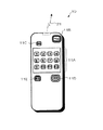
上記ボタン11は、一般的な放送用受信装置に対応させたリモコン装置10では、例えばその概略構成を示す図2において、リモコン装置10の外表面に設けられた、1〜12のチャンネル用ボタン11A、電源ボタン11B、BSチャンネル切替用ボタン11C、画面上でフォーカス(カーソル)が移動した要素を有効とするための決定ボタン11D、および種々の項目を設定するために、項目表示画面を表示させる設定ボタン11Eとを備えており、各ボタン11の押下操作に応じて、赤外発光LED(図示せず)からの赤外線による所定のリモコン信号21が出力されるようになっている。
【0018】
また、図2に示すリモコン装置10は、従来のものに比べてボタン11の数が大幅に削減されている。これは、本実施形態のものにおいては、ボタン11とともに、リモコン装置10の傾き姿勢自体がリモコン命令を入力するための要素となっているからである。
【0019】
また、上述したように、リモコン装置10を傾けると、その傾き量は加速度センサ12によって検出される。加速度センサ12は、加速度の向きを決定する際に重力の向きを基準としており、傾き姿勢を感知するセンサとしても用いることができるため、本実施形態においては、加速度センサ12により、重力の向きと垂直な面内における直交する2軸方向の傾き量を検出し、この検出値に応じたデジタル信号を出力するようにしている。
【0020】
放送用受信装置の表示画面上に並んでいる複数の要素のうちから1つの要素を選択するには、画面内におけるフォーカス(カーソル)を移動させたい方向と同一または対応する方向に、このリモコン装置10を傾けることで、その方向に傾けた回数、あるいはその方向に傾けている時間に亘ってフォーカスを移動させ、所望の要素上にフォーカス(カーソル)が位置している状態で決定ボタン11Dを押下する。
【0021】
そのため、リモコン装置10のボタン11は、上記フォーカスの移動操作完了後に1回だけ押下すればよく、リモコン装置10のボタン操作の簡略化を図ることができる。
【0022】
また、上記リモコン装置10の傾き量を検出する回路は、電源15からの電力を加速度センサ12に供給するか否かのオン/オフを切替えるスイッチ16と、スイッチ16のオン/オフ切替信号を出力するマイクロコンピュータ17を備えることにより、リモコン装置10の非操作時には電源入力をオフ状態とし、リモコン装置10の任意のボタン11が押下されると電源入力をオン状態とし、所定時間(例えば3分間)に亘りボタン11の押下操作がなされない状態が継続すると電源入力をオフ状態として消費電力を節約する機能を有するようになっている。
【0023】
また、リモコン装置10は、それを操作する人の癖などによって、無意識にある傾き姿勢で把持されると考えられる。そこで、上記リモコン装置10の傾き量を検出する回路は、リモコン装置10の電源入力がオン状態とされた時点において加速度センサ12により検出されたリモコン装置10の傾き姿勢を、電源入力がオフ状態となるまで基準姿勢として記憶部13に記憶保持し、この記憶保持された基準姿勢と、その後の時点において加速度センサ12により検出された、リモコン装置10の傾き姿勢との差分に基づき、その後の時点において検出された傾き姿勢が有効な操作によるものか否かをマイコン17により判定し、この判定が有効な操作によるものと判定した場合にのみ、マイコン17により、この傾き姿勢に応じた所定のリモコン信号を記憶部13から読み出すように構成されている。
【0024】
したがって、操作者が意識してリモコン装置10を傾けた場合にのみ、所定のリモコン信号送信操作をなすことが可能となり、リモコン装置10を把持する操作者の癖により、あるいはリモコン装置10を不用意に把持したために、予期しないリモコン信号送信操作がなされる、というような不都合を防止することができる。
【0025】
なお、記憶部13に記憶保持されている基準姿勢は、次にリモコン装置10の電源入力がオン状態とされた時点において検出されるリモコン装置10の基準姿勢により上書きされる。
【0026】
【実施例】
以下、本発明を適用することが特に有用なものの1つであるBSデジタル受信機のリモコン装置の実施例を、上述した図1、および図3、4、5、6を用いて説明する。
【0027】
なお、図3は、BSデジタル受信機のリモコン装置10aのボタン11の配置例を示すものであり、図4は、リモコン装置10a(加速度センサ12)の傾き量と出力パルスのデューティー比との関係の一例を表すグラフであり、また図5は、リモコン装置10aの傾き姿勢に応じた傾き量が検出されることを説明するための図であり、また、図6はBSデジタル放送のデータ放送を利用する際のリモコン装置10aの操作例を示すものである。ここで、本実施例のリモコン装置10aは、基本的には、上記実施形態において説明したリモコン装置10の構成および機能を全て備えている。
【0028】
図1において、複数のボタン群からなるリモコンボタン11が押下されると、マイコン17が押下されたボタン11を認識し、そのボタン11に対応したリモコン信号のコードが記憶部13から読み出される。このコードに応じて、マイコン17がPCM(パルス・コード・モジュレーション)のリモコン信号を生成する。このリモコン信号はリモコン信号変調/送信部14で赤外線信号を変調した後、BSデジタル受信機へ送信される。
【0029】
このような信号の生成、変調、送信方法は、市販されているBSデジタル受信機に付属するリモコン装置と同様の方法が用いられる。また、リモコンボタン11は、上記市販のBSデジタル受信機付属のリモコン装置と同様の機能を有していればよいが、図3に示すように、画面上で要素のフォーカス(カーソル)を“上・下”、“左・右”方向ヘそれぞれ移動させるボタンを省略するように構成することもできる。
【0030】
ここで、図4を用いて、加速度センサ12の傾き量と、この加速度センサ12からの出力パルスとのデューティー比について説明する。加速度センサ12は、リモコン装置10aの傾き量を検出すると、これに応じて、図4(b)に示すように、パルス周期T2(固定)とHレベル期間T1(可変)との比であるデューティー比がT1/T2となるようなパルス信号を出力する。すなわち、リモコン装置10aの傾き姿勢が水平となっているときにはデューティー比が0.5のパルス信号を出力し、これを基準として、左側に傾いているとき(傾き量が負)にはデューティー比が0.5よりも小さく、右側に傾いているとき(傾き量が正)にはデューティー比が0.5よりも大きくなるようなパルス信号が出力される。
【0031】
図4のグラフはこのことを示すものであり、リモコン装置10aの前側(前後方向の軸)が上下方向に傾いた場合にも、同様のパルス信号が出力される。ただし、この上下方向の傾き量に応じたパルス信号は、上記の左右方向のパルス信号とは識別可能な構成とし、リモコン装置10aが傾けられると、加速度センサ12からは、2つの軸方向の傾き量毎にそれぞれ独立したパルス信号をマイコン17に送出する。
【0032】
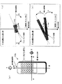
このことを図5を用いて、より具体的に説明する。このリモコン装置10aにおいては、図5(a)に示すように、前後方向および左右方向の直交する2軸方向の傾き姿勢がそれぞれ検出される。ここで、図5(b)はこのリモコン装置10aを図5(a)中のYの位置から見た図であり、図5(c)はこのリモコン装置10aを図5(a)中のXの位置から見た図である。
【0033】
図5(b)に示すように、リモコン装置10aの右側を、傾きの基準値(水平位置)から重力の向きへ傾けると左右方向軸の傾き量を示すデューティー比が0.5より大きくなる。逆に左側を、傾きの基準値(水平位置)から重力の向きへ傾けるとこのデューティー比が0.5より小さくなる。
【0034】
一方、図5(c)に示すように、リモコン装置10aの後側を傾きの基準値から重力の向きへ傾けると、リモコン装置10aの前側は上方向に傾き(やや上方向を向き)、前後方向軸の傾き量を示すデューティー比が0.5より大きくなる。
逆にリモコン装置10aの前側を傾きの基準値から重力の向きへ傾けると、リモコン装置10aの前側は下方向に傾き(やや下方向を向く)、デューティー比が0.5より小さくなる。
【0035】
なお、加速度センサ12は電源入力がオン状態とされている場合には、常にリモコン装置10aの傾き量(傾き姿勢)を検知し、図4(b)に示すごときパルス信号をマイコン17に送出する。
【0036】
マイコン17は、加速度センサ12に電力が供給されている期間において、記憶部13に記憶保持されている基準姿勢値Aと、リモコン装置10aを傾けた時に出力された傾き姿勢値Bとの相対値であるB−Aを算出し、その値が、“上・下”、“左・右”それぞれの方向において、所定の基準値を超えたら(上記デューティー比の絶対値が所定値を超えたら)、その方向に軸が傾けられた(有効な傾き姿勢である)と判定する。そして、このように判定されると、市販されているBSデジタル受信機のリモコンボタンの“上・下”および“左・右”の各方向矢印ボタンを押下した場合と同様のリモコン信号を生成し、リモコン信号変調/送信部14で赤外線を変調してBSデジタル受信機へ送信する。
【0037】
なお、上述したように、上記前後の軸が傾くことにより、リモコン装置10aの前側が上下方向に傾き、操作者にとって、このリモコン装置10aを傾ける操作が、設定画面上でフォーカス(カーソル)を上下方向に移動させる操作と感覚的に合致することになる。
【0038】
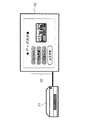
次に、上述したBSデジタル受信機のリモコン装置10aによる、BSデジタル放送のデータ放送を利用する際の操作例について図3および図6を用いて説明する。この例においては、BSデジタル放送受信機31にハイビジョン用のディスプレイ32が接続されており、ディスプレイ32の表示画面内にBSデジタル放送のデータ放送に関する各要素33が表示されている。
【0039】
まず、BSデジタル放送において、データ放送を利用するためには、図3に示すごときリモコン装置10aの「d」ボタン11Fを押下する。この時点でスイッチ16がオン状態となるため、加速度センサ12の電源入力がオン状態となり、傾きの基準値が記憶部13に記憶される。次に、リモコン装置10aを“上・下”、“左・右”いずれかの方向へ複数回傾け(あるいは所定時間に亘って傾け)、図6に示す如きデータ放送の設定画面上において、フォーカス(カーソル)を所望の要素33の位置まで移動させる。この状態で「決定」ボタン11Gを押下すると、所望のデータ放送番組が受信される(図6の例では、台風情報のデータ放送が受信される)。
【0040】
なお、上述した実施例においては、リモコン装置10aの基本的な機能について説明しているが、状況に応じてその他の機能を付加することは勿論可能である。例えば、操作者が意図する“傾き”の傾き量は操作者によって異なるため、その差異を補償するための“傾き”の感度調節機能を備えるようにしてもよい。
【0041】
具体的には、リモコン装置10aが傾けられたと判定する傾き量のしきい値を数種類決め、予めマイコン17に記憶させておき、操作者がリモコン装置10aを使用する際に、必要に応じて、ボタン操作等によってそのしきい値を選択するようにしてもよいし、操作者がボタン操作等によって所望のしきい値に設定するようにしてもよい。
【0042】
また、上記リモコン装置10aを所定時間傾けた場合の機能は、パソコン等を用いて設定および設定変更が可能となるように構成してもよい。
【0043】
また、本発明のリモコン信号送信装置の傾き姿勢検出手段としては上記加速度センサに限られるものではなく、リモコン信号送信装置の傾き姿勢を良好に検出し、その検出値に応じた信号を出力し得るものであればその他の種類のセンサを用いることが可能である。
【0044】
また、上記のように、傾き姿勢を検出する直交の2軸を、前後方向および左右方向としているが、その他の直交する2軸とすることも可能である。
【0045】
また、上述した各リモコンボタンの押下操作に応じて、赤外線による所定のリモコン信号を出力する赤外発光LEDは、赤外線の指向性を広くするために複数個用いるようにすることが望ましい。
【0046】
【発明の効果】
本発明のリモコン信号送信装置によれば、傾き姿勢検出手段により検出された傾き姿勢に基づき、所定のリモコン信号が被遠隔操作機器(放送用受信装置)に対して送出されるようにしており、リモコン信号送信装置を移動させる方向とその速さに応じてリモコンコードが決定される従来技術のように、送信されるリモコンコードを決定するための操作が不正確になり易いという問題を解消でき、また、回路構成やソフトウェアも簡素になる。
【0047】
したがって、リモコン信号送信装置のリモコンコードの設定を不正確なものとすることなく、その設定操作を簡便なものとすることができる。
【0048】
また、特にBSデジタル放送におけるデータ放送のように、設定画面上の複数要素の中から、フォーカス(カーソル)を移動させて所望の要素を選択する必要がある場合に、リモコン信号送信装置を傾け、その傾けた方向と同じ方向に上記フォーカスを移動できるようにし、要素を決定(確定)する際にのみリモコン信号送信装置のボタンを押下するように構成することで、リモコン信号送信装置のボタン操作を大幅に簡略化できる。
【図面の簡単な説明】
【図1】本発明の実施形態に係るリモコン信号送信装置の概略構成を示すブロック図
【図2】本発明の実施形態に係るリモコン信号送信装置のリモコンボタン配置の概略を示す図
【図3】本発明の実施例に係るBSデジタル受信機のリモコン装置のボタンの配置例を示す図
【図4】図1に示す加速度センサの傾き量と、この加速度センサからの出力パルスのデューティー比との関係を示すグラフ(a)およびその出力パルスのデューティー比を定義するための図(b)
【図5】図3に示すリモコン装置の傾き姿勢に応じた傾き量が検出されることを説明するための図
【図6】図3に示すリモコン装置の、BSデジタル放送のデータ放送を利用する際の操作例を説明するための図
【符号の説明】
10、10a リモコン装置
11 リモコンボタン
12 加速度センサ
13 記憶部
14 リモコン信号変調/送信部
15 電源
16 スイッチ
17 マイクロコンピュータ
21 リモコン信号
31 BSデジタル放送受信機
32 ディスプレイ
33 要素[0001]
TECHNICAL FIELD OF THE INVENTION
The present invention relates to a remote control signal transmitting device for transmitting a predetermined remote control signal to a remotely controlled device to be remotely controlled, and more particularly to a remote control signal transmitting device for remotely controlling a broadcast receiving device such as a television or a VTR. It is about.
[0002]
[Prior art]
2. Description of the Related Art Conventionally, a remote control signal transmission device (hereinafter, simply referred to as a remote control device) for remotely controlling a broadcast receiving device such as a television or a VTR is provided on a surface of the remote control device when inputting a command to the remote control device. Generally, various operation buttons are pressed.
[0003]
However, many recent broadcast receivers have a large number of functions, and in many cases, selecting a desired operation button from various types of operation buttons is considered to be troublesome.
[0004]
In particular, in BS digital broadcasting, which has been rapidly spreading in recent years, data broadcasting (including interactive services) which is a text and image service, and EPG (electronic program guide) data for displaying the contents of programs to be broadcast are also included. Being broadcast. In these services, it is necessary to perform an operation to select one of a plurality of selection elements (for example, see FIG. 6) arranged on the display screen of the broadcast receiving device.
[0005]
In order to select one of the plurality of selection elements as described above, a remote control device is used, and a remote control button for moving in each of up, down, left, and right directions is appropriately pressed, and focus ( In general, the user moves the cursor (cursor) and presses the "decision" remote control button when the focus (cursor) matches the desired selection element. Therefore, it is necessary to press a large number of remote control buttons before obtaining desired information, and it is necessary to perform operation while comparing the display screen of the broadcast receiver and the remote control buttons as needed.
[0006]
In order to reduce the complexity of such button operations, when an operator shakes a remote control, a predetermined remote control code is transmitted to a broadcast receiving device in accordance with the direction of the shake and the speed of the shake. It has been known.
[0007]
[Patent Document 1]
JP-A-4-334197 (Patent No. 2641638)
[0008]
[Problems to be solved by the invention]
However, in the technology described in
[0009]
That is, the operator may be confused as to how fast the remote control should be shaken for a valid operation, and when a different remote control code is determined depending on the speed of the shake, the operation is difficult. There was a problem of becoming.
[0010]
The present invention has been made in view of such circumstances, and it is an object of the present invention to provide a remote control signal transmission device capable of simplifying the setting operation without making the setting of the remote control code of the remote control signal transmission device inaccurate. It is intended to do so.
[0011]
[Means for Solving the Problems]
In order to achieve the above object, a remote control signal transmitting device of the present invention is a remote control signal transmitting device that transmits a predetermined remote control signal to a remotely controlled device to be remotely controlled,
A tilt attitude detecting means for detecting a tilt attitude of the remote control signal transmission device,
Remote control signal storage means for storing a remote control signal defined in advance so as to correspond to the tilt posture of the remote control signal transmitting device,
Remote control signal reading means for reading a predetermined remote control signal from the remote control signal storage means based on the tilt attitude detected by the tilt attitude detection means;
Remote control signal transmitting means for transmitting a remote control signal read from the remote control signal reading means to the remote controlled device.
[0012]
In this case, the circuit for detecting the tilt posture of the remote control signal transmitting device in the tilt posture detecting means is such that when the remote control signal transmitting device is not operated, the power input is turned off, and any circuit of the remote control signal transmitting device is turned off. The power input is turned on when an operation element is operated, and the power input is turned off at a point in time when a predetermined time has elapsed since the operation element was operated. preferable.
[0013]
Further, the tilt attitude of the remote control signal transmitting device, which is detected by the tilt attitude detecting means when the power input of the circuit is turned on, is stored and held as a reference attitude until the power input is turned off. Reference attitude storage means,
Based on the difference between the reference attitude stored in the reference attitude storage means and the tilt attitude of the remote control signal transmission device detected by the tilt attitude detection means at a later point in time, Effective operation determination means for determining whether the tilt posture is due to a valid operation,
The remote control signal reading unit is configured to read the predetermined remote control signal corresponding to the tilt posture from the remote control signal storage unit only for the tilt posture determined by the valid operation determining unit to be a valid operation. Is preferred.
[0014]
BEST MODE FOR CARRYING OUT THE INVENTION
Hereinafter, a remote control signal transmission device according to an embodiment of the present invention will be described with reference to the drawings.
[0015]
A remote control signal transmission device according to the present embodiment (hereinafter, referred to as a remote control device) is a remote control device that transmits a predetermined remote control signal to a broadcast receiving device such as a television or a VTR on which a remote control operation is performed. By detecting a tilt posture of the remote control device and transmitting a remote control signal corresponding to the detected tilt posture, button operations of the remote control device are simplified.
[0016]
That is, the
[0017]
In the
[0018]
Further, the number of
[0019]
Further, as described above, when the
[0020]
In order to select one element from a plurality of elements arranged on the display screen of the broadcast receiving apparatus, the remote control apparatus is set in the same or corresponding direction as the direction in which the focus (cursor) in the screen is to be moved. By inclining 10, the focus is moved for the number of times of inclining in that direction or the time of inclining in that direction, and the
[0021]
Therefore, the
[0022]
The circuit for detecting the amount of tilt of the
[0023]
In addition, it is considered that the
[0024]
Therefore, it is possible to perform a predetermined remote control signal transmission operation only when the operator is consciously tilting the
[0025]
The reference posture stored and stored in the
[0026]
【Example】
Hereinafter, an embodiment of a remote control device for a BS digital receiver, which is one of the applications to which the present invention is particularly useful, will be described with reference to FIGS. 1 and 3, 4, 5, and 6 described above.
[0027]
FIG. 3 shows an example of the arrangement of the
[0028]
In FIG. 1, when a
[0029]
As a method of generating, modulating, and transmitting such a signal, a method similar to a remote control device attached to a commercially available BS digital receiver is used. The
[0030]
Here, the duty ratio between the amount of inclination of the
[0031]
The graph in FIG. 4 illustrates this, and a similar pulse signal is output even when the front side (axis in the front-rear direction) of the
[0032]
This will be described more specifically with reference to FIG. In the
[0033]
As shown in FIG. 5B, when the right side of the
[0034]
On the other hand, as shown in FIG. 5C, when the rear side of the
Conversely, when the front side of the
[0035]
When the power input is turned on, the
[0036]
The
[0037]
As described above, when the front and rear axes are tilted, the front side of the
[0038]
Next, an operation example of using the BS digital broadcast data broadcast by the
[0039]
First, in order to use data broadcasting in BS digital broadcasting, the "d"
[0040]
In the above-described embodiment, the basic functions of the
[0041]
More specifically, several types of threshold values of the amount of tilt for determining that the
[0042]
In addition, the function when the
[0043]
Further, the inclination posture detecting means of the remote control signal transmission device of the present invention is not limited to the above-mentioned acceleration sensor, but can detect the inclination posture of the remote control signal transmission device satisfactorily and output a signal corresponding to the detected value. Other types of sensors can be used.
[0044]
In addition, as described above, the two orthogonal axes for detecting the inclination posture are the front-back direction and the left-right direction, but other orthogonal two axes may be used.
[0045]
In addition, it is desirable to use a plurality of infrared light emitting LEDs that output a predetermined remote control signal using infrared rays in response to the pressing operation of each remote control button described above in order to broaden the directivity of infrared rays.
[0046]
【The invention's effect】
According to the remote control signal transmission device of the present invention, a predetermined remote control signal is transmitted to a remotely operated device (broadcast receiving device) based on the tilt posture detected by the tilt posture detection means, As in the related art in which the remote control code is determined according to the moving direction and the speed of the remote control signal transmission device, it is possible to solve the problem that the operation for determining the remote control code to be transmitted is likely to be inaccurate, Also, the circuit configuration and software are simplified.
[0047]
Therefore, the setting operation can be simplified without setting the remote control code of the remote control signal transmitting device inaccurately.
[0048]
Further, when it is necessary to select a desired element by moving a focus (cursor) from a plurality of elements on a setting screen, such as a data broadcast in BS digital broadcasting, tilt the remote control signal transmitting device, The focus can be moved in the same direction as the tilted direction, and the button of the remote control signal transmission device is pressed only when the element is determined (determined), so that the button operation of the remote control signal transmission device can be performed. It can be greatly simplified.
[Brief description of the drawings]
FIG. 1 is a block diagram illustrating a schematic configuration of a remote control signal transmitting apparatus according to an embodiment of the present invention. FIG. 2 is a schematic view illustrating an arrangement of remote control buttons of the remote control signal transmitting apparatus according to the embodiment of the present invention. FIG. 4 is a diagram showing an example of button arrangement of a remote control device of the BS digital receiver according to the embodiment of the present invention. FIG. 4 shows a relationship between an inclination amount of the acceleration sensor shown in FIG. 1 and a duty ratio of an output pulse from the acceleration sensor. (A) showing a graph and a diagram (b) for defining a duty ratio of an output pulse thereof.
5 is a diagram for explaining that a tilt amount corresponding to the tilt posture of the remote control device shown in FIG. 3 is detected. FIG. 6 uses a BS digital broadcast data broadcast of the remote control device shown in FIG. For explaining an operation example at the time of operation [Explanation of reference numerals]
10, 10a
Claims (4)
当該リモコン信号送信装置の傾き姿勢を検出する傾き姿勢検出手段と、
前記リモコン信号送信装置の傾き姿勢と対応するようにして予め定義されたリモコン信号を記憶するリモコン信号記憶手段と、
前記傾き姿勢検出手段により検出された傾き姿勢に基づき、所定のリモコン信号を前記リモコン信号記憶手段から読み出すリモコン信号読出手段と、
前記リモコン信号読出手段から読み出されたリモコン信号を前記被遠隔操作機器に対して送出するリモコン信号送出手段とを備えたことを特徴とするリモコン信号送信装置。In a remote control signal transmitting device that transmits a predetermined remote control signal to a remote controlled device to be remotely controlled,
A tilt attitude detecting means for detecting a tilt attitude of the remote control signal transmission device,
Remote control signal storage means for storing a remote control signal defined in advance so as to correspond to the tilt posture of the remote control signal transmitting device,
Remote control signal reading means for reading a predetermined remote control signal from the remote control signal storage means based on the tilt attitude detected by the tilt attitude detection means;
A remote control signal transmitting unit for transmitting a remote control signal read from the remote control signal reading unit to the remotely operated device.
該基準姿勢記憶手段に記憶された基準姿勢と、その後の時点において前記傾き姿勢検出手段により検出された、前記リモコン信号送信装置の傾き姿勢との差分に基づき、前記その後の時点において検出された前記傾き姿勢が有効な操作によるものか否かを判定する有効操作判定手段とを備え、
前記リモコン信号読出手段は、前記有効操作判定手段が有効な操作によるものと判定した前記傾き姿勢についてのみ、該傾き姿勢に応じた前記リモコン信号を前記リモコン信号記憶手段から読み出すように構成されていることを特徴とする請求項1または2記載のリモコン信号送信装置。A reference attitude for storing and holding the tilt attitude of the remote control signal transmission device, detected by the tilt attitude detection means at the time when the power input of the circuit is turned on, as the reference attitude until the power input is turned off. Storage means;
Based on the difference between the reference attitude stored in the reference attitude storage means and the tilt attitude of the remote control signal transmission device detected by the tilt attitude detection means at a later point in time, Effective operation determination means for determining whether the tilt posture is due to a valid operation,
The remote control signal reading unit is configured to read the remote control signal corresponding to the tilt posture from the remote control signal storage unit only for the tilt posture determined by the valid operation determination unit to be a valid operation. The remote control signal transmission device according to claim 1 or 2, wherein:
Priority Applications (1)
| Application Number | Priority Date | Filing Date | Title |
|---|---|---|---|
| JP2003022810A JP4064255B2 (en) | 2003-01-30 | 2003-01-30 | Remote control signal transmitter |
Applications Claiming Priority (1)
| Application Number | Priority Date | Filing Date | Title |
|---|---|---|---|
| JP2003022810A JP4064255B2 (en) | 2003-01-30 | 2003-01-30 | Remote control signal transmitter |
Publications (2)
| Publication Number | Publication Date |
|---|---|
| JP2004236034A true JP2004236034A (en) | 2004-08-19 |
| JP4064255B2 JP4064255B2 (en) | 2008-03-19 |
Family
ID=32951789
Family Applications (1)
| Application Number | Title | Priority Date | Filing Date |
|---|---|---|---|
| JP2003022810A Expired - Fee Related JP4064255B2 (en) | 2003-01-30 | 2003-01-30 | Remote control signal transmitter |
Country Status (1)
| Country | Link |
|---|---|
| JP (1) | JP4064255B2 (en) |
Cited By (8)
| Publication number | Priority date | Publication date | Assignee | Title |
|---|---|---|---|---|
| JP2007104567A (en) * | 2005-10-07 | 2007-04-19 | Sharp Corp | Electronic equipment |
| JP2008085603A (en) * | 2006-09-27 | 2008-04-10 | Sharp Corp | Remote controlled transmitter |
| JP2010212774A (en) * | 2009-03-06 | 2010-09-24 | Softbank Mobile Corp | Remote operation method and remote operation system for electric apparatus, and communication terminal device and communication relay device used for the remote operation system |
| JP2012205209A (en) * | 2011-03-28 | 2012-10-22 | Mitsubishi Electric Corp | Remote control transmitter |
| JP2013536660A (en) * | 2010-08-31 | 2013-09-19 | ヴォルフガング・ブレンデル | Wireless remote control by position sensor system |
| JP2014216718A (en) * | 2013-04-23 | 2014-11-17 | 株式会社東海理化電機製作所 | Remote control system |
| JP2016187159A (en) * | 2015-03-27 | 2016-10-27 | パナソニックIpマネジメント株式会社 | Remote control system and electronic equipment |
| JP2020127586A (en) * | 2019-02-07 | 2020-08-27 | 株式会社トプコン | Ophthalmologic apparatus |
-
2003
- 2003-01-30 JP JP2003022810A patent/JP4064255B2/en not_active Expired - Fee Related
Cited By (9)
| Publication number | Priority date | Publication date | Assignee | Title |
|---|---|---|---|---|
| JP2007104567A (en) * | 2005-10-07 | 2007-04-19 | Sharp Corp | Electronic equipment |
| JP2008085603A (en) * | 2006-09-27 | 2008-04-10 | Sharp Corp | Remote controlled transmitter |
| JP2010212774A (en) * | 2009-03-06 | 2010-09-24 | Softbank Mobile Corp | Remote operation method and remote operation system for electric apparatus, and communication terminal device and communication relay device used for the remote operation system |
| JP2013536660A (en) * | 2010-08-31 | 2013-09-19 | ヴォルフガング・ブレンデル | Wireless remote control by position sensor system |
| JP2012205209A (en) * | 2011-03-28 | 2012-10-22 | Mitsubishi Electric Corp | Remote control transmitter |
| JP2014216718A (en) * | 2013-04-23 | 2014-11-17 | 株式会社東海理化電機製作所 | Remote control system |
| US9454861B2 (en) | 2013-04-23 | 2016-09-27 | Kabushiki Kaisha Tokai Rika Denki Seisakusho | Remote control system |
| JP2016187159A (en) * | 2015-03-27 | 2016-10-27 | パナソニックIpマネジメント株式会社 | Remote control system and electronic equipment |
| JP2020127586A (en) * | 2019-02-07 | 2020-08-27 | 株式会社トプコン | Ophthalmologic apparatus |
Also Published As
| Publication number | Publication date |
|---|---|
| JP4064255B2 (en) | 2008-03-19 |
Similar Documents
| Publication | Publication Date | Title |
|---|---|---|
| US11830355B2 (en) | Electronic apparatus, control method thereof, remote control apparatus, and control method thereof | |
| US5561543A (en) | Information input system by attitude detection of manual implement | |
| EP1832323B1 (en) | Video game device and storage medium storing video game program | |
| US10152115B2 (en) | Generating position information employing an imager | |
| US20090072992A1 (en) | Remote control for sensing movement, image display apparatus for controlling pointer by the remote control, and controlling method thereof | |
| US20070075971A1 (en) | Remote controller, image processing apparatus, and imaging system comprising the same | |
| US8184211B2 (en) | Quasi analog knob control method and appartus using the same | |
| US7123180B1 (en) | System and method for controlling an electronic device using a single-axis gyroscopic remote control | |
| JP4064255B2 (en) | Remote control signal transmitter | |
| EP1184982B1 (en) | Remote control device | |
| JP4533290B2 (en) | Remote control device | |
| JP3651757B2 (en) | Remote control device and in-vehicle navigation device | |
| US20020126089A1 (en) | Remote control unit and system | |
| JP5119972B2 (en) | Image playback system | |
| JP2007263839A (en) | Navigation system | |
| JP5157631B2 (en) | Camera system | |
| KR0170646B1 (en) | Menu selecting apparatus | |
| KR19990065817A (en) | OSD menu screen remote control device and remote control method | |
| KR101674939B1 (en) | Method for setting up user interface circumstance and Digital broadcasting receiver enabling of the method | |
| KR100918935B1 (en) | Motion sensing remote controller | |
| KR20100027882A (en) | Remocon and method for operating the same | |
| KR20050122859A (en) | Method for controlling a digital tv by using a wireless mouse | |
| KR200280504Y1 (en) | Monitoring apparatus for easy controllability of play speed | |
| JP2008085603A (en) | Remote controlled transmitter | |
| JPH07236188A (en) | Remote commander |
Legal Events
| Date | Code | Title | Description |
|---|---|---|---|
| A621 | Written request for application examination |
Free format text: JAPANESE INTERMEDIATE CODE: A621 Effective date: 20050411 |
|
| A977 | Report on retrieval |
Free format text: JAPANESE INTERMEDIATE CODE: A971007 Effective date: 20070906 |
|
| A131 | Notification of reasons for refusal |
Free format text: JAPANESE INTERMEDIATE CODE: A131 Effective date: 20070913 |
|
| A521 | Written amendment |
Free format text: JAPANESE INTERMEDIATE CODE: A523 Effective date: 20071107 |
|
| TRDD | Decision of grant or rejection written | ||
| A01 | Written decision to grant a patent or to grant a registration (utility model) |
Free format text: JAPANESE INTERMEDIATE CODE: A01 Effective date: 20071210 |
|
| A61 | First payment of annual fees (during grant procedure) |
Free format text: JAPANESE INTERMEDIATE CODE: A61 Effective date: 20071226 |
|
| R150 | Certificate of patent or registration of utility model |
Free format text: JAPANESE INTERMEDIATE CODE: R150 |
|
| FPAY | Renewal fee payment (event date is renewal date of database) |
Free format text: PAYMENT UNTIL: 20110111 Year of fee payment: 3 |
|
| FPAY | Renewal fee payment (event date is renewal date of database) |
Free format text: PAYMENT UNTIL: 20120111 Year of fee payment: 4 |
|
| FPAY | Renewal fee payment (event date is renewal date of database) |
Free format text: PAYMENT UNTIL: 20130111 Year of fee payment: 5 |
|
| FPAY | Renewal fee payment (event date is renewal date of database) |
Free format text: PAYMENT UNTIL: 20140111 Year of fee payment: 6 |
|
| LAPS | Cancellation because of no payment of annual fees |