JP2004233480A - Stereoscopic endoscope system - Google Patents
Stereoscopic endoscope system Download PDFInfo
- Publication number
- JP2004233480A JP2004233480A JP2003019775A JP2003019775A JP2004233480A JP 2004233480 A JP2004233480 A JP 2004233480A JP 2003019775 A JP2003019775 A JP 2003019775A JP 2003019775 A JP2003019775 A JP 2003019775A JP 2004233480 A JP2004233480 A JP 2004233480A
- Authority
- JP
- Japan
- Prior art keywords
- distance
- image
- pair
- subject
- magnification
- Prior art date
- Legal status (The legal status is an assumption and is not a legal conclusion. Google has not performed a legal analysis and makes no representation as to the accuracy of the status listed.)
- Granted
Links
Images

Landscapes
- Endoscopes (AREA)
- Instruments For Viewing The Inside Of Hollow Bodies (AREA)
Abstract
Description
【0001】
【発明の属する技術分野】
本発明は、視差のある左右の像を得ることが可能な撮像システムを有し、その2つの像に基づいて立体視用画像を画面に表示する立体表示システムに関し、特に、観察部位を立体視しながら手術等を行うことができる立体内視鏡システムに関する。
【0002】
【従来の技術】
従来、視差を有する左右の像が得られるように観察部位を撮像し、その視差のある像(視差画像)を表示させて立体視を可能にする立体表示システムが知られている。特に、開腹等をせずに内視鏡を使用して手術をする「低浸襲手術」において、観察部位を立体視することが可能な立体内視鏡システムが知られている(例えば、特許文献1)。特許文献1では、立体内視鏡の先端部における画角αとHMD(Head Mount Display)の視角βの条件式が示されており、さらに、奥行き感を得るための入射瞳間隔Eと内視鏡挿入部の外径Dとの関係が明らかにされている。
【0003】
【特許文献1】
特開平8−313828号公報
(段落〔0023〕〜〔0032〕、第3−4図)
【0004】
【発明が解決しようとする課題】
特許文献1では、先端部から観察部位までの距離をX、先端部の外径Dとした場合、XとDとの関係が、“X=2D”と規定されている。しかしながら、内視鏡を使用して縫合や止血クリッピングを行う場合、観察部位までの距離は術者の作業状況によって変わるため、特許文献1に示された条件では、術中において奥行き感を得るのが難しく、効率よく適切に手術を行うことができない。
【0005】
そこで本発明では、術中等に安定して立体視することが可能な立体内視鏡システムおよび立体表示システムを得ることを目的とする。
【0006】
【課題を解決するための手段】
本発明の立体内視鏡システムは、視差のある2つの像を形成し、立体視可能となるように立体視用画像を表示する立体内視鏡システムであり、手術下において術者が十分に立体視できるように構成されている。立体内視鏡システムの1つの構成としては、立体視用内視鏡と立体視用の画像信号処理装置とが備えられ、例えば2眼2カメラ方式の硬性鏡と、シャッタ機能付き眼鏡を用いた立体表示方式による画像処理装置とが設けられる。本発明の1つの特徴を示す立体内視鏡システムは、被写体を立体視可能にするため一対の撮像素子を有する撮像部と、1つの被写体から視差のある一対の像を形成し、一対の撮像素子に結像させる光学系と、撮像素子から読み出される一対の像に応じた一対の画像信号に基づいて、立体視用画像を表示装置に表示させる信号処理手段とを備える。
【0007】
本発明の立体内視鏡システムは、以下の式を満たすことを特徴とする。
0.00102 ≦ |M×m×p×Δs/(s×L)| ≦ 0.0091
ここで、Mは電気的拡大率、mは内視鏡内に設けられた光学系の光学倍率、pは光学系における入射瞳間隔の半分の距離、sは焦点位置から内視鏡先端までの距離、Δsは被写体の奥行き間隔、そして、Lは観察者から表示画面までの距離を示す。なお、電気的拡大率Mは、立体視用内視鏡内に設けられた撮像素子に形成される被写体像と表示画面に表示される被写体像との大きさ(サイズ)に関する比を示す。この式の下限値は、従来の開腹手術下において術者が知覚している立体感と同等の立体感(奥行き感)を最低限感じさせる必要があるとの考えにより定められており、奥行き間隔を過度に強調して立体視することが困難になる閾値を上限値として定めている。
【0008】
一方、ビュアー方式による本発明の立体内視鏡システムは、拡大観察用光学系を介して立体視される立体内視鏡システムであって、拡大観察用光学系は、表示装置の立体視用画像を光学的に拡大する。この場合、立体内視鏡システムは、以下の式を満たすことを特徴とする。
0.00102 ≦|M×m×p×Δs/(s×L’)| ≦ 0.0091
ただし、L’は拡大観察用光学系による仮想の観察者から表示画面までの距離を示す。
【0009】
本発明の立体表示システムは、視差のある2つの像を形成し、立体視可能となるように立体視用画像を表示する立体表示システムであって、内視鏡の有無に関係なく立体表示可能である。立体表示システムは、以下の式を満たすことを特徴とする。
0.00102 ≦ |M×m×p×Δs/(s×L)| ≦ 0.0091
また、ビュアー方式による立体表示システムは、以下の式を満たすことを特徴とする。
0.00102 ≦|M×m×p×Δs/(s×L’)| ≦ 0.0091
【0010】
【発明の実施の形態】
以下では、図面を用いて、本発明の実施形態である立体内視鏡システムについて説明する。
【0011】
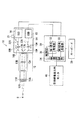
図1は、本実施形態である立体内視鏡システムのブロック図である。本実施形態の立体内視鏡システムは、腹部などに硬性鏡を挿入し、立体視しながら手術を行うための内視鏡システムである。
【0012】
立体内視鏡システムは、硬性鏡10、信号処理装置30、立体映像表示用のモニタ40を備えており、硬性鏡10は信号処理装置30に接続されている。硬性鏡10は、挿入部12および撮像部14から構成されており、患部を立体的に観察可能にする2眼2カメラ方式の電子内視鏡である。挿入部12には、対物レンズ11A、11B、および光学像を撮像部14まで伝達する中継用(リレー)光学系13A、13Bが設けられている。
【0013】
硬性鏡10の先端部12Sに設けられた対物レンズ11Aは観察者の左目用の観察像(以下では、第1の観察像という)を形成する。そして、第1の観察像に応じた光はリレー光学系13Aを介して撮像部14へ伝達される。一方、対物レンズ11Bは右目用の観察像(以下では、第2の観察像という)を形成し、第2の観察像に応じた光はリレー光学系13Bを介して撮像部14へ伝達される。
【0014】
撮像部14には、反射ミラー17A、17B、18A、18B、第1のCCD(Charge−Coupled Device)15、第2のCCD16、およびズームレンズ19A、19Bが設けられており、第1の観察像に応じた光は、反射ミラー17A、18Aにおいて反射され、第1のズームレンズ19Aを介して第1のCCD15に到達する。これにより、第1の観察像がCCD15に形成され、画像信号が発生する。発生した画像信号(以下では、第1の画像信号という)は撮像部14から読み出され、信号処理装置30へ送られる。同様に、第2の観察像に応じた光は、反射ミラー17B、18B、第2のズームレンズ19Bを介して第2のCCD16に到達し、第2の観察像が第2のCCD16上に形成され、画像信号(以下では、第2の画像信号という)が信号処理装置30へ送られる。
【0015】
信号処理装置30には、第1信号処理部32、第2信号処理部33、映像同期部34、制御部35が設けられており、第1の画像信号、第2の画像信号は、それぞれ第1信号処理部32、第2信号処理部33へ送られる。第1信号処理部32、第2信号処理部33では、それぞれ第1の画像信号、第2の画像信号に対して所定の処理が施される。処理された画像信号は、映像同期部34へ送られる。
【0016】
本実施形態では、シャッタ付き眼鏡および時系列表示により立体視を実現させており、観察者はシャッタ機能付き眼鏡(図示せず)を掛けて立体視する。映像同期部34では、第1の観察像および第2の観察像がモニタ40上において交互に時系列表示されるように、第1の画像および第2の画像信号が所定のタイミングで出力される。また、映像同期部34では、1画面上において第1の観察像と第2の観察像とが両眼視差に応じた距離だけ相対的にずれて表示されるように、信号処理が施される。シャッタ機能付き眼鏡では、映像同期部34から出力される第1および第2の画像信号の出力タイミングと同期して左目用シャッタおよび右目用シャッタが交互に切り替えられる。その結果、硬性鏡10によって捉えられた観察部位が立体視される。
【0017】
硬性鏡10の操作部にはズーム操作用レバー21が備えられており、ズーム操作用レバー21が操作されると、第1、第2レンズ駆動機構22A、22Bが動き、操作量に従ってそれぞれ第1、第2のズームレンズ19A、19Bを光軸に沿って移動させる。これにより、硬性鏡10の光学的倍率が変動する。一方、制御部35は、信号処理装置30の動作を制御しており、後述するように電気的拡大率を設定可能である。オペレータが硬性鏡10の光学倍率を設定するためキーボード39を操作すると、それに応じて電気的拡大率が設定される。
【0018】
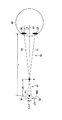
図2は、モニタ画面と観察者との立体視関係を示した図であり、図3は、硬性鏡先端部12Sおよび観察部位における光の軌跡を示した図である。図2、図3を用いて、術中において立体視するための立体内視鏡システムの条件について説明する。
【0019】
まず、立体内視鏡システムを使用した手術において、医師等の観察者が1つの画面上の立体視用画像から観察部位を3次元的に知覚することができるための条件を求める。
【0020】
図2に示すように、モニタ40の表示画面40Sと観察者OHとの距離(以下では、表示距離という)を“L”,眼福の半分の距離を“q”と表す。また、観察対象はオペレータOHの真正面上に知覚されるものとする。すなわち、観察者OHの正面(左目LE、右目REの二等分線となる中心線GH)に観察対象が立体視されるように立体視用映像が画面40Sに表示される。立体視用画像によって観察対象が3次元的に知覚されている場合、その観察対象の先端位置(以下では仮想先端位置という)を“P”と表し、画面40S上にあって中心線GH上にある観察対象点を“P1”と表す。また、表示画面40Sからの距離、すなわち観察対象の奥行き(以下では、仮想奥行き距離という)を“ΔL”と表す。
【0021】
本実施形態では、硬性鏡10によって撮像された観察対象は、「距離Lだけ離れ、“ΔL”だけ奥行きがある」物体として立体視される。そして、そのような立体感を知覚できる立体視用映像がモニタ40に表示される必要があり、表示画面40Sには、左目用の第1の観察像と右目用の第2の観察像とが両眼視差に応じたずれをもって交互に表示される。このとき、第1の観察像と第2の観察像との間における視差によるずれ量の半分の距離(以下では、表示側視差という)を“ΔY”とする。表示側視差ΔYは、中心線GHからのずれた距離に相当する。
【0022】
ここで、左目LEから仮想先端位置Pを通る視線X1が表示画面40S上に到達する点をQ1、右目REから仮想先端位置Pを通る視線X2が表示画面40Sに到達する点をQ2とする。仮想先端位置Pおよび、Q1、Q2を結ぶことで構成される三角形S1と、仮想物体先端Pおよび左目LE,右目REを結ぶことで構成される三角形S2は、相似関係にある。したがって、以下の式が成り立つ。
ΔY/ΔL=q/L ・・・・(11)
(11)式により、表示側視差ΔYは、以下の式に従って定められる。
ΔY=q×ΔL/L ・・・・(12)
【0023】
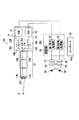
次に、図3を用いて、実際に観察対象を硬性鏡10により撮像した場合に得られる左右の像のずれを求める。ただし、説明を簡単にするため、光学系としては1つの対物レンズ11A、11Bのみ表す。
【0024】
図3に示すように、観察対象となる部位の先端位置を“Z1”、対物レンズ11A、11Bから先端位置Z1までの距離を“s”、観察部位の奥行きを“Δs”、観察部位の先端部12Sから一定距離だけ離れた位置(以下では、最後尾位置という)を“Z2”とする。また、入射瞳間隔(基線長)の半分の距離を“p”、対物レンズ11A、11Bを結ぶ部線GGから第1および第2のCCD15、16までの像距離を“s’”と表す。観察部位は対物レンズ11A、11Bの中心を通る基準線K上にあるものとする。距離sは、対物レンズ11A、11Bの焦点距離に対し十分大きいとき実質的に先端部12Sと観察部位までの距離に等しいため、以下では被写体距離を“s”とする。
【0025】
観察対象の奥行きΔsにより、第1のCCD15、および第2のCCD16の受光面上では、先端位置Z1に応じた像の位置と最後尾位置Z2に応じた像の位置とが異なる。ここでは、この距離(以下では、撮像側視差という)を“Δy”で表す。表示側視差ΔY(図2参照)の大きさは、この撮像側視差Δyに比例する。
【0026】
内視鏡を使用した手術下において、被写体距離sは、観察対象の奥行きΔsに比べて十分長く、Δs≪sとみなせる。よって、基準線Kと最後尾位置Z2から第2のCCD16へ到達する光線R2ととの角度を“θ’”とすると、θ’は入射瞳間隔の半分の距離をp、被写体距離sを用いて以下のように表される。
θ’≒ θ = p/s ・・・・・・(13)
【0027】
先端位置Z1から対物レンズ11Bを通って第2のCCD16に到達する光線を“R1”とし、先端位置Z1を含む断面における光線R1と光線R2との距離を“Δh”とする。ΔhはΔs、θ’を用いて以下のように表される。
Δh=Δs×θ’≒ Δs×p/s ・・・・(14)
また、光学系全体の倍率を“m”とすると、光学倍率mは、被写体距離sと像距離s’あるいは撮像側視差ΔyとΔhを用いて以下のように表される。
m = s’/s = Δy/Δh ・・・・(15)
【0028】
したがって、(14)(15)式より、Δyは、m、p、Δs、sを用いて次式のように表される。
Δy=m×p×Δs/s ・・・(16)
第1の撮影光学系11A、第1のCCD15に関しても、同様に撮像側視差Δyが求められる。
【0029】
なお、s’≪sの場合、s’は実質的に焦点距離fに等しい(s’≒ f)。したがって、Δyは、以下のように焦点距離fを用いて表すことができる。
Δy=(s’/s)×p×Δs/s
=f×p×Δs/s2 ・・・・(17)
【0030】
ここで、第1、第2のCCD15、16に結像される像の大きさに対するモニタ40上の表示画像との比を電気的拡大率“M”とした場合、ΔYとΔyは以下の関係を満たす。
ΔY=|Δy×M| ・・・・(18)
したがって、上記(12)、(17)、(18)式より、以下の関係式が導かれる。
ΔY = q×ΔL/L = |M×m×p×Δs/s| ・・(19)
【0031】
さらに、(19)式の両辺に1/Lを乗じることにより、(19)式は以下のように無次元化して表すことができる。
ΔY/L=(q×ΔL)/L2
=|M×m×p×Δs/(s×L)| ・・・(20)
ΔYが表示側視差を示すことから、ΔY/Lは視差角を表すものとみなせる。表示側視差ΔYが大きいほど、あるいは表示距離Lが小さいほど立体感が得られることから、“ΔY/L”は立体感を表す係数と定義できる。眼福の半分の距離qはおよそ一定とみなせることから、表示距離Lと仮想奥行き距離ΔLとの関係に従って“ΔY/L”の値は変化する。
【0032】
ここで、立体内視鏡システムを利用している状況下においてオペレータに最低限必要な立体感を考える。内視鏡を使用しない開腹手術の下では、術者の眼球位置から観察物体までの距離は、腕を伸ばした長さほどの距離に相当し、およそ500mmである。さらに、開腹術では主に縫合作業が行われるが、そのとき使用される針の大きさは、平均的に8〜10mm程度である。本実施形態では、このような開腹手術下で知覚できる立体感(奥行き感)をオペレータにとって最低限必要な立体感とみなす。すなわち、少なくとも開腹手術により得られる立体感と同等と立体感を立体内視鏡システムによって提供できるように(20)式の下限値を定める。
【0033】
眼福の半分の距離qは平均32mmである。(20)式においてq=32、L=500、ΔL=8を代入すると、(20)式の下限値が以下のように求められる。
(q×ΔL)/L2=32×8/5002=0.00102 ・・(21)
よって、次式が導かれる。
0.00102 ≦ |M×m×p×(Δs/s)×L| ・・(22)
【0034】
一方、光学倍率mあるいは電気的拡大率Mを必要以上に大きくすると、システムの大型化や画質劣化を招く。さらに、奥行き感が過度に強調された立体視用画像をモニタ40に表示させると、オペレータOHは画像の融合がしにくくなり、立体視が困難になる。そこで、(20)式の上限値を以下の条件に基づいて算出する。
【0035】
30歳前後の人の近点は、最も眼球(観察者)に近い場所で6ディオプター(以下、Dで表す)程度である。人間の眼球における焦点調節機能(単眼視でも可能)と輻輳(両眼視による機能)とは連動して一体的に作用することから、この近点での両眼視差によるズレ量が、オペレータの観察可能な限界点とみなせる。(20)式の左辺にL=167(mm)を代入すると、以下のように(20)式の上限値が求められる。
|M×m×p×(Δs/(s×L)| ≦ 0.0091 ・・(23)
本実施形態の立体内視鏡では、(22)式かつ(23)式を満たすように、光学倍率m、電気拡大率Mが定められ、信号処理装置30の制御部35が電気拡大率Mを調整する。
【0036】
ここで、(22)、(23)式を、光学的倍率m、電気的拡大率M、入射瞳間隔の半分の距離pをパラメータとした式で表すことを考える。腹腔鏡手術の場合、立体視が要求される作業は主に縫合作業であり、針の大きさが8〜10mm、観察部位までの距離は40〜100mmである。したがって、Δs/sは、少なくとも1/10あればよい。Δs=10、s=100とすると、以下の式が成り立つ。
10.2 ≦ |(M×m×p)/L| ≦ 91.0 ・・・(24)
【0037】
次に、図4を用いて第2の実施形態について説明する。第2の実施形態では、表示装置の前に光学系を配置するビュアー方式によって立体視される。それ以外の構成については、第1の実施形態と実質的に同じである。
【0038】
図4は、第2の実施形態である立体内視鏡システムのブロック図である。
【0039】
信号処理装置30Aには一対の表示装置40Aが接続されており、第1信号処理部32から出力される第1の画像信号は第1の表示部41へ出力され、第2信号処理部33から出力される第2の画像信号は第1の表示部42へ出力される。これにより、第1の表示部41、第2の表示部42にそれぞれ左目、右目用の視差のある画像が表示される。さらに、一対の表示装置40AとオペレータOHとの間にはルーペRPが配置され、オペレータOHはルーペRPを介して立体視する。ルーペRPは左目用の第1レンズ43、右目用の第2レンズ44から構成され、第1の表示部41、第2の表示部42にそれぞれ表示された画像が拡大観察される。
【0040】
ルーペRPは、仮想的に観察距離をルーペ焦点距離fe[mm]以下まで近づける機能をもつ。仮想の観察距離を“L’”と表した場合、仮想観察距離L’は以下の式で表される。ただし、仮想観察距離L’は、いわゆる機械近視(オペレータOHの視度が−1D)の状態に基づいて定められる。
L’=fe−fe2/1000 ・・・(25)
したがって、ビュアー方式の立体内視鏡システムでは、次式の関係が成り立つ。0.00102 ≦|M×m×p×(Δs/(s×L’)| ≦ 0.0091
・・・(26)
【0041】
なお、立体表示方法については、第1、第2実施形態で示した表示方法以外の方法(例えば、HMD方式など)によって立体視させてもよい。また、2眼2カメラ方式以外の立体視用硬性鏡(1眼2カメラ方式など)を使用してもよい。また、軟性鏡に適用することも可能である。
【0042】
第1、第2実施形態では、開腹手術下の条件に従って(22)式を導いているが、内視鏡を使用しない立体表示システムにも適用可能である。この場合、その立体表示システムが適用される環境(ロボット遠隔操作など)に従って上限値、下限値を求めればよい。
【0043】
【発明の効果】
以上のように本発明によれば、術中等に安定して立体視することが可能である。
【図面の簡単な説明】
【図1】第1の実施形態である立体内視鏡システムのブロック図である。
【図2】モニタ画面と観察者との立体視関係を示した図である。
【図3】硬性鏡先端部および観察部位における光の軌跡を示した図である。
【図4】第2の実施形態である立体内視鏡システムのブロック図である。
【符号の説明】
10 硬性鏡
11A、11B 対物レンズ
13A、13B リレー系レンズ
15 第1のCCD
16 第2のCCD
19A、19B ズームレンズ
30、30A 信号処理装置
40、40A モニタ[0001]
TECHNICAL FIELD OF THE INVENTION
The present invention relates to a stereoscopic display system having an imaging system capable of obtaining left and right images with parallax, and displaying a stereoscopic image on a screen based on the two images. The present invention relates to a stereoscopic endoscope system capable of performing an operation or the like while operating.
[0002]
[Prior art]
2. Description of the Related Art Conventionally, there has been known a stereoscopic display system which captures an observation region so that left and right images having parallax are obtained, and displays an image having parallax (parallax image) to enable stereoscopic viewing. In particular, a stereoscopic endoscope system capable of stereoscopically observing a part to be observed in “low invasive surgery” in which an operation is performed using an endoscope without performing an abdomen or the like is known (for example, Patent Reference 1).
[0003]
[Patent Document 1]
JP-A-8-313828 (paragraphs [0023] to [0032], FIG. 3-4)
[0004]
[Problems to be solved by the invention]
In
[0005]
Therefore, an object of the present invention is to provide a stereoscopic endoscope system and a stereoscopic display system capable of stably performing stereoscopic vision during an operation or the like.
[0006]
[Means for Solving the Problems]
The stereoscopic endoscope system of the present invention is a stereoscopic endoscope system that forms two images with parallax and displays a stereoscopic image so that the image can be stereoscopically viewed. It is configured to enable stereoscopic viewing. One configuration of the stereoscopic endoscope system includes a stereoscopic endoscope and a stereoscopic image signal processing device, and uses, for example, a two-lens two-camera rigid mirror and glasses with a shutter function. And an image processing apparatus using a stereoscopic display method. A stereoscopic endoscope system according to one aspect of the present invention includes an imaging unit having a pair of imaging elements for enabling a subject to be viewed stereoscopically, and forming a pair of images having parallax from one subject to form a pair of images. An optical system for forming an image on the element, and signal processing means for displaying a stereoscopic image on a display device based on a pair of image signals corresponding to a pair of images read from the imaging element.
[0007]
The stereoscopic endoscope system of the present invention is characterized by satisfying the following expression.
0.00102 ≦ | M × m × p × Δs / (s × L) | ≦ 0.0091
Here, M is an electrical magnification, m is an optical magnification of an optical system provided in the endoscope, p is a half distance of an entrance pupil interval in the optical system, and s is a distance from a focus position to a tip of the endoscope. The distance, Δs indicates the depth interval of the subject, and L indicates the distance from the observer to the display screen. Note that the electrical magnification ratio M indicates a ratio of a subject image formed on an image sensor provided in the endoscope for stereoscopic vision to a subject image displayed on a display screen. The lower limit of this formula is determined based on the idea that it is necessary to make the operator feel at least a stereoscopic effect (depth effect) equivalent to the stereoscopic effect perceived by the operator under conventional laparotomy. Is excessively emphasized, and a threshold value at which stereoscopic viewing becomes difficult is determined as an upper limit value.
[0008]
On the other hand, the stereoscopic endoscope system of the present invention based on the viewer system is a stereoscopic endoscope system that is stereoscopically viewed through an optical system for magnifying observation, and the optical system for magnifying observation is a stereoscopic image of a display device. Is optically magnified. In this case, the stereoscopic endoscope system is characterized by satisfying the following equation.
0.00102 ≦ | M × m × p × Δs / (s × L ′) | ≦ 0.0091
Here, L 'indicates the distance from the virtual observer to the display screen by the magnifying observation optical system.
[0009]
The stereoscopic display system of the present invention is a stereoscopic display system that forms two images with parallax and displays a stereoscopic image so that stereoscopic viewing is possible. It is. The stereoscopic display system is characterized by satisfying the following expression.
0.00102 ≦ | M × m × p × Δs / (s × L) | ≦ 0.0091
Further, the stereoscopic display system based on the viewer system is characterized by satisfying the following expression.
0.00102 ≦ | M × m × p × Δs / (s × L ′) | ≦ 0.0091
[0010]
BEST MODE FOR CARRYING OUT THE INVENTION
Hereinafter, a stereoscopic endoscope system according to an embodiment of the present invention will be described with reference to the drawings.
[0011]
FIG. 1 is a block diagram of a stereoscopic endoscope system according to the present embodiment. The stereoscopic endoscope system of the present embodiment is an endoscope system for performing an operation while stereoscopically viewing by inserting a rigid endoscope into an abdomen or the like.
[0012]
The stereoscopic endoscope system includes a
[0013]
The
[0014]
The
[0015]
The
[0016]
In the present embodiment, stereoscopic vision is realized by glasses with shutters and time-series display, and the observer wears glasses with shutter functions (not shown) to perform stereoscopic vision. In the
[0017]
The operation unit of the
[0018]
FIG. 2 is a diagram showing a stereoscopic relationship between a monitor screen and an observer, and FIG. 3 is a diagram showing a trajectory of light at a
[0019]
First, in an operation using a stereoscopic endoscope system, a condition for an observer such as a doctor to be able to three-dimensionally perceive an observation region from a stereoscopic image on one screen is obtained.
[0020]
As shown in FIG. 2, the distance between the display screen 40S of the
[0021]
In the present embodiment, the observation target imaged by the
[0022]
Here, the point at which the line of sight X1 passing through the virtual tip position P from the left eye LE reaches the display screen 40S is Q1, and the point at which the line of sight X2 passing through the virtual tip position P from the right eye RE reaches the display screen 40S is Q2. A triangle S1 formed by connecting the virtual tip position P and Q1 and Q2 and a triangle S2 formed by connecting the virtual object tip P and the left eye LE and the right eye RE have a similar relationship. Therefore, the following equation holds.
ΔY / ΔL = q / L (11)
According to the equation (11), the display-side parallax ΔY is determined according to the following equation.
ΔY = q × ΔL / L (12)
[0023]
Next, using FIG. 3, the deviation between the left and right images obtained when the observation target is actually imaged by the
[0024]
As shown in FIG. 3, the tip position of the part to be observed is “Z1”, the distance from the
[0025]
The position of the image corresponding to the front end position Z1 and the position of the image corresponding to the rearmost position Z2 are different on the light receiving surfaces of the
[0026]
Under the operation using the endoscope, the subject distance s is sufficiently longer than the depth Δs of the observation target, and can be regarded as Δs≪s. Therefore, assuming that the angle between the reference line K and the ray R2 reaching the
θ ′ ≒ θ = p / s (13)
[0027]
The light beam that reaches the
Δh = Δs × θ ′ ≒ Δs × p / s (14)
Further, assuming that the magnification of the entire optical system is “m”, the optical magnification m is expressed as follows using the subject distance s and the image distance s ′ or the imaging-side parallaxes Δy and Δh.
m = s' / s = Δy / Δh (15)
[0028]
Therefore, from equations (14) and (15), Δy is expressed as follows using m, p, Δs, and s.
Δy = m × p × Δs / s (16)
Similarly, the imaging-side parallax Δy is obtained for the first imaging
[0029]
In the case of s'ss, s 'is substantially equal to the focal length f (s' ≒ f). Therefore, Δy can be expressed using the focal length f as follows.
Δy = (s ′ / s) × p × Δs / s
= F × p × Δs / s 2 (17)
[0030]
Here, when the ratio of the size of the image formed on the first and
ΔY = | Δy × M | (18)
Therefore, the following relational expressions are derived from the above expressions (12), (17), and (18).
ΔY = q × ΔL / L = | M × m × p × Δs / s | (19)
[0031]
Further, by multiplying both sides of the expression (19) by 1 / L, the expression (19) can be expressed in a dimensionless manner as follows.
ΔY / L = (q × ΔL) / L 2
= | M × m × p × Δs / (s × L) | (20)
Since ΔY indicates the display-side parallax, ΔY / L can be regarded as representing the parallax angle. The larger the display-side parallax ΔY or the smaller the display distance L, the more the three-dimensional effect is obtained. Therefore, “ΔY / L” can be defined as a coefficient representing the three-dimensional effect. Since the distance q that is half of the eyesight can be regarded as substantially constant, the value of “ΔY / L” changes according to the relationship between the display distance L and the virtual depth distance ΔL.
[0032]
Here, consider the minimum stereoscopic effect required by the operator under the situation where the stereoscopic endoscope system is used. Under laparotomy without using an endoscope, the distance from the operator's eyeball position to the object to be observed is equivalent to the length of the extended arm, and is about 500 mm. Furthermore, suturing is mainly performed in laparotomy, and the size of the needle used at that time is about 8 to 10 mm on average. In the present embodiment, the three-dimensional effect (depth effect) that can be perceived under such a laparotomy is regarded as the minimum required three-dimensional effect for the operator. That is, the lower limit of the expression (20) is determined so that the stereoscopic endoscope system can provide a stereoscopic effect at least equivalent to the stereoscopic effect obtained by open surgery.
[0033]
The distance q that is half of the eyesight is 32 mm on average. By substituting q = 32, L = 500, and ΔL = 8 in equation (20), the lower limit of equation (20) is obtained as follows.
(Q × ΔL) / L 2 = 32 × 8/500 2 = 0.00102 (21)
Therefore, the following equation is derived.
0.00102 ≦ | M × m × p × (Δs / s) × L | (22)
[0034]
On the other hand, if the optical magnification m or the electric magnification M is increased more than necessary, the system becomes large and the image quality deteriorates. Further, when a stereoscopic image in which the sense of depth is excessively emphasized is displayed on the
[0035]
The near point of a person around the age of 30 is about 6 diopters (hereinafter, referred to as D) at a position closest to the eyeball (observer). Since the focus adjustment function (possible even with monocular vision) and the convergence (function with binocular vision) in the human eyeball work in conjunction with each other, the amount of displacement due to binocular parallax at this near point is determined by the operator. It can be regarded as the observable limit. When L = 167 (mm) is substituted into the left side of Expression (20), the upper limit of Expression (20) is obtained as follows.
| M × m × p × (Δs / (s × L) | ≦ 0.0091 (23)
In the stereoscopic endoscope of the present embodiment, the optical magnification m and the electric magnification M are determined so as to satisfy the expressions (22) and (23), and the
[0036]
Here, it is considered that the expressions (22) and (23) are expressed by using the optical magnification m, the electric magnification M, and the distance p, which is a half of the entrance pupil interval, as parameters. In the case of laparoscopic surgery, operations requiring stereoscopic vision are mainly suturing operations, and the size of the needle is 8 to 10 mm, and the distance to the observation site is 40 to 100 mm. Therefore, Δs / s may be at least 1/10. If Δs = 10 and s = 100, the following equation holds.
10.2 ≦ | (M × mx × p) /L|≦91.0 (24)
[0037]
Next, a second embodiment will be described with reference to FIG. In the second embodiment, stereoscopic viewing is performed by a viewer system in which an optical system is arranged in front of a display device. Other configurations are substantially the same as those of the first embodiment.
[0038]
FIG. 4 is a block diagram of a stereoscopic endoscope system according to the second embodiment.
[0039]
A pair of display devices 40A is connected to the signal processing device 30A. The first image signal output from the first signal processing unit 32 is output to the
[0040]
The loupe RP has a function of virtually reducing the observation distance to the loupe focal length fe [mm] or less. When the virtual observation distance is represented by “L ′”, the virtual observation distance L ′ is represented by the following equation. However, the virtual observation distance L 'is determined based on the state of so-called mechanical myopia (the diopter of the operator OH is -1D).
L '= fe-fe 2/ 1000 ··· (25)
Therefore, in the viewer-type stereoscopic endoscope system, the following relationship is established. 0.00102 ≦ | M × m × p × (Δs / (s × L ′) | ≦ 0.0091
... (26)
[0041]
As for the stereoscopic display method, stereoscopic viewing may be performed by a method other than the display method described in the first and second embodiments (for example, an HMD method). Further, a rigid stereoscope (such as a one-lens two-camera system) other than the two-lens two-camera system may be used. It is also possible to apply to a flexible endoscope.
[0042]
In the first and second embodiments, the expression (22) is derived according to the conditions under open surgery, but the present invention can also be applied to a stereoscopic display system that does not use an endoscope. In this case, the upper limit value and the lower limit value may be obtained according to the environment to which the stereoscopic display system is applied (such as remote operation of a robot).
[0043]
【The invention's effect】
As described above, according to the present invention, it is possible to perform a stereoscopic view stably during an operation or the like.
[Brief description of the drawings]
FIG. 1 is a block diagram of a stereoscopic endoscope system according to a first embodiment.
FIG. 2 is a diagram showing a stereoscopic relationship between a monitor screen and an observer.
FIG. 3 is a diagram showing a trajectory of light at a distal end portion of a rigid endoscope and an observation site.
FIG. 4 is a block diagram of a stereoscopic endoscope system according to a second embodiment.
[Explanation of symbols]
10
16 Second CCD
19A,
Claims (12)
以下の式を満たすことを特徴とする立体内視鏡システム。
0.00102 ≦ |M×m×p×Δs/(s×L)| ≦ 0.0091
・・・・・(1)
ただし、Mは電気的拡大率、mは光学倍率、pは入射瞳間隔の半分の距離、sは被写体から内視鏡先端までの距離、Δsは被写体の奥行き間隔、そして、Lは観察者から表示画面までの距離を示す。In a stereoscopic endoscope system that forms two images with parallax and displays a stereoscopic image so that stereoscopic viewing is possible,
A stereoscopic endoscope system characterized by satisfying the following expression.
0.00102 ≦ | M × m × p × Δs / (s × L) | ≦ 0.0091
・ ・ ・ ・ ・ (1)
Where M is the electrical magnification, m is the optical magnification, p is the distance of half the entrance pupil interval, s is the distance from the subject to the endoscope end, Δs is the depth interval of the subject, and L is the distance from the observer. Indicates the distance to the display screen.
以下の式を満たすことを特徴とする立体内視鏡システム。
0.00102 ≦|M×m×p×Δs/(s×L’)| ≦ 0.0091
・・・・(2)
ただし、Mは電気的拡大率、mは光学倍率、pは入射瞳間隔の半分の距離、sは被写体から内視鏡先端までの距離、Δsは被写体の奥行き間隔、そして、L’は拡大観察用光学系による仮想の観察者から表示画面までの距離を示す。In a stereoscopic endoscope system that forms two images with parallax and displays a stereoscopic image so that stereoscopic viewing is possible, and is stereoscopically viewed through an optical system for magnifying observation,
A stereoscopic endoscope system characterized by satisfying the following expression.
0.00102 ≦ | M × m × p × Δs / (s × L ′) | ≦ 0.0091
.... (2)
Where M is the electrical magnification, m is the optical magnification, p is the distance of half the entrance pupil interval, s is the distance from the subject to the endoscope end, Δs is the depth interval of the subject, and L ′ is the magnification observation. The distance from the virtual observer to the display screen by the optical system is shown.
1つの被写体から視差のある一対の像を形成し、前記一対の撮像素子に結像させる光学系と、
撮像素子から読み出される前記一対の像に応じた一対の画像信号に基づいて、立体視用画像を表示装置に表示させる信号処理手段とを備え、
以下の式を満たすように、光学系の光学倍率および信号処理手段における電気的拡大率とが定められることを特徴とする立体内視鏡システム。
0.00102 ≦ |M×m×p×Δs/(s×L)| ≦ 0.0091
・・・・・(3)
ただし、Mは電気的拡大率、mは光学倍率、pは入射瞳間隔の半分の距離、sは被写体から内視鏡先端までの距離、Δsは被写体の奥行き間隔、Lは観察者から表示画面までの距離を示す。An imaging unit having a pair of imaging elements to enable a subject to be stereoscopically viewed,
An optical system that forms a pair of images having parallax from one subject and forms an image on the pair of imaging elements;
Signal processing means for displaying a stereoscopic image on a display device based on a pair of image signals corresponding to the pair of images read from the imaging element,
A stereoscopic endoscope system wherein an optical magnification of an optical system and an electric magnification in a signal processing unit are determined so as to satisfy the following expression.
0.00102 ≦ | M × m × p × Δs / (s × L) | ≦ 0.0091
・ ・ ・ ・ ・ (3)
Where M is the electrical magnification, m is the optical magnification, p is the distance of half the entrance pupil interval, s is the distance from the subject to the end of the endoscope, Δs is the depth interval of the subject, and L is the display screen from the observer. Indicates the distance to.
1つの被写体から視差のある一対の像を形成し、前記一対の撮像素子に結像させる光学系と、
前記撮像素子から読み出される前記一対の像に応じた一対の画像信号に基づいて、立体視用画像を表示装置に表示させる信号処理手段と、
前記表示装置の立体視用画像を光学的に拡大する拡大観察用光学系とを備え、以下の式を満たすように、前記光学系の光学倍率および前記信号処理手段における電気的拡大率とが定められることを特徴とする立体内視鏡システム。
0.00102 ≦|M×m×p×Δs/(s×L’)| ≦ 0.0091
・・・・(4)
ただし、Mは電気的拡大率、mは光学倍率、pは入射瞳間隔の半分の距離、sは被写体から内視鏡先端までの距離、Δsは被写体の奥行き間隔、そして、L’は拡大観察用光学系による仮想の観察者から表示画面までの距離を示す。An imaging unit having a pair of imaging elements to enable a subject to be stereoscopically viewed,
An optical system that forms a pair of images having parallax from one subject and forms an image on the pair of imaging elements;
Signal processing means for displaying a stereoscopic image on a display device based on a pair of image signals corresponding to the pair of images read from the image sensor,
An optical system for magnifying observation for optically enlarging a stereoscopic image of the display device, wherein an optical magnification of the optical system and an electric magnification in the signal processing unit are determined so as to satisfy the following expression. A stereoscopic endoscope system, characterized in that
0.00102 ≦ | M × m × p × Δs / (s × L ′) | ≦ 0.0091
... (4)
Where M is the electrical magnification, m is the optical magnification, p is the distance of half the entrance pupil interval, s is the distance from the subject to the endoscope end, Δs is the depth interval of the subject, and L ′ is the magnification observation. The distance from the virtual observer to the display screen by the optical system is shown.
前記撮像素子から読み出される前記一対の像に応じた一対の画像信号に基づいて、立体視用画像信号を生成する信号処理手段と、
前記立体視用画像を表示する表示手段と備え、
以下の式を満たすように、前記信号処理手段における電気的拡大率が定められることを特徴とする立体内視鏡システムの画像処理装置。
0.00102 ≦ |M×m×p×Δs/(s×L)| ≦ 0.0091
・・・・・(5)
ただし、Mは電気的拡大率、mは光学倍率、pは入射瞳間隔の半分の距離、sは被写体から内視鏡先端までの距離、Δsは被写体の奥行き間隔、そして、Lは観察者から表示画面までの距離を示す。An image pickup unit having a pair of image sensors for enabling a subject to be viewed stereoscopically, and an optical system that forms a pair of images having parallax from one subject and forms an image on the pair of image pickup devices. An image processing apparatus of a stereoscopic endoscope system connected to an endoscope,
Signal processing means for generating a stereoscopic image signal based on a pair of image signals corresponding to the pair of images read from the image sensor,
Display means for displaying the stereoscopic image,
An image processing apparatus for a stereoscopic endoscope system, wherein an electrical magnification in the signal processing means is determined so as to satisfy the following expression.
0.00102 ≦ | M × m × p × Δs / (s × L) | ≦ 0.0091
・ ・ ・ ・ ・ (5)
Where M is the electrical magnification, m is the optical magnification, p is the distance of half the entrance pupil interval, s is the distance from the subject to the endoscope end, Δs is the depth interval of the subject, and L is the distance from the observer. Indicates the distance to the display screen.
被写体を立体視可能にするため一対の撮像素子を有する撮像部と、
1つの被写体から視差のある一対の像を形成し、前記一対の撮像素子に結像させる光学系とを備え、
以下の式を満たすように、前記光学系の光学倍率が定められることを特徴とする立体視用内視鏡。
0.00102 ≦ |M×m×p×Δs/(s×L)| ≦ 0.0091
・・・・・(6)
ただし、Mは電気的拡大率、mは光学倍率、pは入射瞳間隔の半分の距離、sは被写体から内視鏡先端までの距離、Δsは被写体の奥行き間隔、Lは観察者から表示画面までの距離を示す。A stereoscopic endoscope connected to the image processing device of the stereoscopic endoscope system according to claim 7,
An imaging unit having a pair of imaging elements to enable a subject to be stereoscopically viewed,
An optical system that forms a pair of images having parallax from one subject and forms an image on the pair of imaging elements;
The stereoscopic endoscope, wherein an optical magnification of the optical system is determined so as to satisfy the following expression.
0.00102 ≦ | M × m × p × Δs / (s × L) | ≦ 0.0091
・ ・ ・ ・ ・ (6)
Where M is the electrical magnification, m is the optical magnification, p is the distance of half the entrance pupil interval, s is the distance from the subject to the end of the endoscope, Δs is the depth interval of the subject, and L is the display screen from the observer. Indicates the distance to.
前記撮像素子から読み出される前記一対の像に応じた一対の画像信号に基づいて、立体視用画像信号を生成する信号処理手段と、
前記立体視用画像を表示する表示手段と、
前記表示手段により表示される立体視用画像を光学的に拡大する拡大観察用光学系とを備え、
以下の式を満たすように、前記信号処理手段における電気的拡大率が定められることを特徴とする立体内視鏡システムの画像処理装置。
0.00102 ≦|M×m×p×Δs/(s×L’)| ≦ 0.0091
・・・・(7)
ただし、Mは電気的拡大率、mは光学倍率、pは入射瞳間隔の半分の距離、sは被写体から内視鏡先端までの距離、Δsは被写体の奥行き間隔、そして、L’は拡大観察用光学系による仮想の観察者から表示画面までの距離を示す。An image pickup unit having a pair of image sensors for enabling a subject to be viewed stereoscopically, and an optical system that forms a pair of images having parallax from one subject and forms an image on the pair of image pickup devices. An image processing apparatus of a stereoscopic endoscope system connected to an endoscope,
Signal processing means for generating a stereoscopic image signal based on a pair of image signals corresponding to the pair of images read from the image sensor,
Display means for displaying the stereoscopic image,
An optical system for magnifying observation for optically enlarging a stereoscopic image displayed by the display means,
An image processing apparatus for a stereoscopic endoscope system, wherein an electrical magnification in the signal processing means is determined so as to satisfy the following expression.
0.00102 ≦ | M × m × p × Δs / (s × L ′) | ≦ 0.0091
... (7)
Where M is the electrical magnification, m is the optical magnification, p is the distance of half the entrance pupil interval, s is the distance from the subject to the endoscope end, Δs is the depth interval of the subject, and L ′ is the magnification observation. The distance from the virtual observer to the display screen by the optical system is shown.
被写体を立体視可能にするため一対の撮像素子を有する撮像部と、
1つの被写体から視差のある一対の像を形成し、前記一対の撮像素子に結像させる光学系とを備え、
以下の式を満たすように、前記光学系の光学倍率が定められることを特徴とする立体視用内視鏡。
0.00102 ≦|M×m×p×Δs/(s×L’)| ≦ 0.0091
・・・・(8)
ただし、Mは電気的拡大率、mは光学倍率、pは入射瞳間隔の半分の距離、sは被写体から内視鏡先端までの距離、Δsは被写体の奥行き間隔、L’は拡大観察用光学系による仮想の観察者から表示画面までの距離を示す。A stereoscopic endoscope connected to the image processing device of the stereoscopic endoscope system according to claim 9,
An imaging unit having a pair of imaging elements to enable a subject to be stereoscopically viewed,
An optical system that forms a pair of images having parallax from one subject and forms an image on the pair of imaging elements;
The stereoscopic endoscope, wherein an optical magnification of the optical system is determined so as to satisfy the following expression.
0.00102 ≦ | M × m × p × Δs / (s × L ′) | ≦ 0.0091
・ ・ ・ ・ (8)
Here, M is the electrical magnification, m is the optical magnification, p is the distance of half of the entrance pupil distance, s is the distance from the subject to the tip of the endoscope, Δs is the depth distance of the subject, and L ′ is the magnification observation optical. The distance from the virtual observer to the display screen by the system is shown.
1つの被写体から視差のある一対の像を形成し、前記一対の撮像素子に結像させる光学系と、
前記撮像素子から読み出される前記一対の像に応じた一対の画像信号に基づいて、立体視用画像を表示装置に表示させる信号処理手段とを備え、
以下の式を満たすように、前記光学系の光学倍率および前記信号処理手段における電気的拡大率とが定められることを特徴とする立体表示システム。
0.00102 ≦ |M×m×p×Δs/(s×L)| ≦ 0.0091
・・・・・(9)
ただし、Mは電気的拡大率、mは光学倍率、pは入射瞳間隔の半分の距離、sは被写体から内視鏡先端までの距離、Δsは被写体の奥行き間隔、そして、Lは観察者から表示画面までの距離を示す。An imaging unit having a pair of imaging elements to enable a subject to be stereoscopically viewed,
An optical system that forms a pair of images having parallax from one subject and forms an image on the pair of imaging elements;
Signal processing means for displaying a stereoscopic image on a display device based on a pair of image signals corresponding to the pair of images read from the image sensor,
A three-dimensional display system, wherein an optical magnification of the optical system and an electric magnification in the signal processing unit are determined so as to satisfy the following expression.
0.00102 ≦ | M × m × p × Δs / (s × L) | ≦ 0.0091
・ ・ ・ ・ ・ (9)
Where M is the electrical magnification, m is the optical magnification, p is the distance of half the entrance pupil interval, s is the distance from the subject to the endoscope end, Δs is the depth interval of the subject, and L is the distance from the observer. Indicates the distance to the display screen.
1つの被写体から視差のある一対の像を形成し、前記一対の撮像素子に結像させる光学系と、
前記撮像素子から読み出される前記一対の像に応じた一対の画像信号に基づいて、立体視用画像を表示装置に表示させる信号処理手段と、
前記表示装置の立体視用画像を光学的に拡大する拡大観察用光学系とを備え、
以下の式を満たすように、前記光学系の光学倍率および前記信号処理手段における電気的拡大率とが定められることを特徴とする立体表示システム。
0.00102 ≦|M×m×p×Δs/(s×L’)| ≦ 0.0091
・・・・(10)
ただし、Mは電気的拡大率、mは光学倍率、pは入射瞳間隔の半分の距離、sは被写体から内視鏡先端までの距離、Δsは被写体の奥行き間隔、そして、L’は拡大観察用光学系による仮想の観察者から表示画面までの距離を示す。An imaging unit having a pair of imaging elements to enable a subject to be stereoscopically viewed,
An optical system that forms a pair of images having parallax from one subject and forms an image on the pair of imaging elements;
Signal processing means for displaying a stereoscopic image on a display device based on a pair of image signals corresponding to the pair of images read from the image sensor,
An optical system for magnifying observation for optically enlarging a stereoscopic image of the display device,
A three-dimensional display system, wherein an optical magnification of the optical system and an electric magnification in the signal processing unit are determined so as to satisfy the following expression.
0.00102 ≦ | M × m × p × Δs / (s × L ′) | ≦ 0.0091
... (10)
Where M is the electrical magnification, m is the optical magnification, p is the distance of half the entrance pupil interval, s is the distance from the subject to the endoscope end, Δs is the depth interval of the subject, and L ′ is the magnification observation. The distance from the virtual observer to the display screen by the optical system is shown.
Priority Applications (1)
| Application Number | Priority Date | Filing Date | Title |
|---|---|---|---|
| JP2003019775A JP4246510B2 (en) | 2003-01-29 | 2003-01-29 | Stereoscopic endoscope system |
Applications Claiming Priority (1)
| Application Number | Priority Date | Filing Date | Title |
|---|---|---|---|
| JP2003019775A JP4246510B2 (en) | 2003-01-29 | 2003-01-29 | Stereoscopic endoscope system |
Publications (2)
| Publication Number | Publication Date |
|---|---|
| JP2004233480A true JP2004233480A (en) | 2004-08-19 |
| JP4246510B2 JP4246510B2 (en) | 2009-04-02 |
Family
ID=32949568
Family Applications (1)
| Application Number | Title | Priority Date | Filing Date |
|---|---|---|---|
| JP2003019775A Expired - Fee Related JP4246510B2 (en) | 2003-01-29 | 2003-01-29 | Stereoscopic endoscope system |
Country Status (1)
| Country | Link |
|---|---|
| JP (1) | JP4246510B2 (en) |
Cited By (4)
| Publication number | Priority date | Publication date | Assignee | Title |
|---|---|---|---|---|
| EP1626567A2 (en) | 2004-08-10 | 2006-02-15 | Konica Minolta Medical & Graphic, Inc. | Image processing system and image processing method |
| CN103458767A (en) * | 2011-08-26 | 2013-12-18 | 奥林巴斯医疗株式会社 | Medical equipment system |
| CN103767669A (en) * | 2012-10-18 | 2014-05-07 | 广州宝胆医疗器械科技有限公司 | Hard multichannel three-dimensional arthroscope system |
| JP2015036060A (en) * | 2013-08-13 | 2015-02-23 | オリンパスメディカルシステムズ株式会社 | Three-dimensional image system |
-
2003
- 2003-01-29 JP JP2003019775A patent/JP4246510B2/en not_active Expired - Fee Related
Cited By (4)
| Publication number | Priority date | Publication date | Assignee | Title |
|---|---|---|---|---|
| EP1626567A2 (en) | 2004-08-10 | 2006-02-15 | Konica Minolta Medical & Graphic, Inc. | Image processing system and image processing method |
| CN103458767A (en) * | 2011-08-26 | 2013-12-18 | 奥林巴斯医疗株式会社 | Medical equipment system |
| CN103767669A (en) * | 2012-10-18 | 2014-05-07 | 广州宝胆医疗器械科技有限公司 | Hard multichannel three-dimensional arthroscope system |
| JP2015036060A (en) * | 2013-08-13 | 2015-02-23 | オリンパスメディカルシステムズ株式会社 | Three-dimensional image system |
Also Published As
| Publication number | Publication date |
|---|---|
| JP4246510B2 (en) | 2009-04-02 |
Similar Documents
| Publication | Publication Date | Title |
|---|---|---|
| JP5730339B2 (en) | Stereoscopic endoscope device | |
| US9756315B2 (en) | Endoscopic system to display three-dimensional picture | |
| JP5284731B2 (en) | Stereoscopic image display system | |
| JP3984907B2 (en) | Image observation system | |
| JP2013521941A (en) | 3D visualization system | |
| JP4537916B2 (en) | Medical stereoscopic observation system | |
| JP2004309930A (en) | Stereoscopic observation system | |
| JPH06194580A (en) | Stereoscopic viewing endoscope and its device | |
| JP2017509925A (en) | 3D video microscope equipment | |
| JP6912313B2 (en) | Image processing device, camera device and image processing method | |
| JP2006158452A (en) | Medical three-dimensional imaging apparatus | |
| JP2006158452A5 (en) | ||
| JP2006208407A (en) | Microscopic system for observing stereoscopic picture | |
| JP2005334462A (en) | Stereoscopic vision endoscope system | |
| JP2019029876A (en) | Image processing apparatus, camera apparatus, and output control method | |
| JP2014110910A (en) | Stereoscopic endoscope apparatus | |
| JP5946777B2 (en) | Stereo imaging device | |
| JP2004320722A (en) | Stereoscopic observation system | |
| WO2017138187A1 (en) | Image pickup device, stereoscopic endoscope, and stereoscopic endoscope system | |
| JP3816599B2 (en) | Body cavity treatment observation system | |
| JP3869029B2 (en) | Stereoscopic endoscope system | |
| JP2004337247A (en) | Three-dimensional observation system | |
| WO2016194446A1 (en) | Information processing device, information processing method, and in-vivo imaging system | |
| JP4246510B2 (en) | Stereoscopic endoscope system | |
| JP2002085330A (en) | Stereoscopic endoscope device |
Legal Events
| Date | Code | Title | Description |
|---|---|---|---|
| A621 | Written request for application examination |
Free format text: JAPANESE INTERMEDIATE CODE: A621 Effective date: 20051003 |
|
| A711 | Notification of change in applicant |
Free format text: JAPANESE INTERMEDIATE CODE: A712 Effective date: 20080501 |
|
| A977 | Report on retrieval |
Free format text: JAPANESE INTERMEDIATE CODE: A971007 Effective date: 20081008 |
|
| A131 | Notification of reasons for refusal |
Free format text: JAPANESE INTERMEDIATE CODE: A131 Effective date: 20081014 |
|
| A521 | Written amendment |
Free format text: JAPANESE INTERMEDIATE CODE: A523 Effective date: 20081204 |
|
| TRDD | Decision of grant or rejection written | ||
| A01 | Written decision to grant a patent or to grant a registration (utility model) |
Free format text: JAPANESE INTERMEDIATE CODE: A01 Effective date: 20090106 |
|
| A01 | Written decision to grant a patent or to grant a registration (utility model) |
Free format text: JAPANESE INTERMEDIATE CODE: A01 |
|
| A61 | First payment of annual fees (during grant procedure) |
Free format text: JAPANESE INTERMEDIATE CODE: A61 Effective date: 20090108 |
|
| R150 | Certificate of patent or registration of utility model |
Free format text: JAPANESE INTERMEDIATE CODE: R150 |
|
| FPAY | Renewal fee payment (event date is renewal date of database) |
Free format text: PAYMENT UNTIL: 20120116 Year of fee payment: 3 |
|
| FPAY | Renewal fee payment (event date is renewal date of database) |
Free format text: PAYMENT UNTIL: 20130116 Year of fee payment: 4 |
|
| LAPS | Cancellation because of no payment of annual fees |