JP2004227406A - Image processor, program and storage medium - Google Patents
Image processor, program and storage medium Download PDFInfo
- Publication number
- JP2004227406A JP2004227406A JP2003016326A JP2003016326A JP2004227406A JP 2004227406 A JP2004227406 A JP 2004227406A JP 2003016326 A JP2003016326 A JP 2003016326A JP 2003016326 A JP2003016326 A JP 2003016326A JP 2004227406 A JP2004227406 A JP 2004227406A
- Authority
- JP
- Japan
- Prior art keywords
- image
- feature amount
- regions
- region
- function
- Prior art date
- Legal status (The legal status is an assumption and is not a legal conclusion. Google has not performed a legal analysis and makes no representation as to the accuracy of the status listed.)
- Pending
Links
Images


Abstract
Description
【0001】
【発明の属する技術分野】
本発明は、画像処理装置、プログラム及び記憶媒体に関する。
【0002】
【従来の技術】
近年、スキャナ、デジタルカメラ、コンピュータ、複写機、複合機(MFP)等の画像処理装置の普及に伴い、デジタル画像データをメモリやハードディスク等の記憶装置に記憶したり、CD−ROM等の光ディスクに記憶したり、さらには、インターネット等を介して伝送したりすることが身近なものになっている。特に、最近では、コンピュータや複合機等が画像サーバとして使用されることも多くなっている。このような画像データには様々な画像処理が行われる。
【0003】
例えば、複合機等の一般的な画像処理の流れとしては、
▲1▼画像入力→傾き角度検出→傾き角度補正→領域識別処理→文字認識処理
▲2▼画像入力→傾き角度検出→傾き角度補正→タイトル抽出→タイトルを文書管理のファイル名等に使用
▲3▼カラー画像入力→2値化処理→傾き角度検出(その後▲1▼又は▲2▼の処理と同様)
▲4▼カラー画像入力→2値化処理(その後▲3▼の処理と同様)→文字領域又はタイトル領域の文字色を特定→再現表示
等の処理がある。
【0004】
また、画像を検索する画像処理(又は画像を分類する画像処理)の流れのとしては、
▲5▼画像入力→特徴量抽出→特徴量が近い画像を検索(その後分類)
というような処理が一般的である。ここで、特徴量としては、色、テクスチャやエッジ情報等がある。
【0005】
このような画像処理の流れの中で実行される様々な技術が提案されている。例えば、複数の解像度の画像データを保存し、出力装置に適した解像度の画像を選択出力する技術(例えば、特許文献1参照)、複数の解像度の画像データを生成し、各解像度の画像から罫線を抽出する技術(例えば、特許文献2参照)、複数の解像度の画像データを生成し、文字種に基づいて最適な解像度を取得し、その後、文字認識処理を行う技術(例えば、特許文献3参照)等が提案されている。
【0006】
一方、最近では、各種の技術により簡単に高精細な画像を得ることができるが、このような高精細静止画像のデータサイズは大きくなる傾向にあり、高精細静止画像の取扱いは困難になってきている。こうした高精細静止画像の取扱いを容易にする画像圧縮伸長アルゴリズムとしては、現在、JPEG(Joint PhotographicExperts Group)や2001年に国際標準となったJPEG後継の画像圧縮伸長方式JPEG2000等が用いられている。このJPEG2000により圧縮された画像データの特徴としては、複数の解像度の画像を有しており、タイリング処理により1つの画像が予め複数の領域(タイル領域)に分割されており、周波数成分(LL成分、LH成分、HL成分、HH成分)の情報を予め有していること等がある。
【0007】
【特許文献1】
特開2000−187725公報
【特許文献2】
特開2001−127972公報
【特許文献3】
特開2002−24766公報
【0008】
【発明が解決しようとする課題】
従来の技術では、複数の解像度の画像データを生成したり、生成された複数の解像度の画像データを保存したり、あるいは、画像を複数の領域に分割したり、特徴量であるエッジ情報を求めたりする必要がある。このように様々な処理を実行する必要があるため、画像処理のシステム規模が大きくなってしまい、画像処理の処理時間も長くなってしまう。
【0009】
また、従来の技術では、画像の一部分から特徴量を抽出することが多いため、画像を検索又は分類する場合等、画像比較が精度良く行われず、その結果として、画像の検索又は分類が正確に行われないことがある。
【0010】
本発明の目的は、システム規模の縮小及び処理時間の短縮を実現することができる画像処理装置、プログラム及び記憶媒体を提供することである。
【0011】
本発明の目的は、画像比較を精度良く実行することができる画像処理装置、プログラム及び記憶媒体を提供することである。
【0012】
【課題を解決するための手段】
請求項1記載の発明の画像処理装置は、各々複数の領域に分割され圧縮された第1の画像と第2の画像とから各々複数の領域毎に特徴量を抽出する特徴量抽出手段と、前記特徴量抽出手段により前記第1の画像と前記第2の画像とから各々複数の領域毎に抽出された特徴量に基づいて、前記第1の画像と前記第2の画像とを比較する画像比較手段と、を備える。
【0013】
したがって、各々複数の領域に分割され圧縮された第1の画像と第2の画像とから各々複数の領域毎に特徴量を抽出し、抽出した特徴量に基づいて第1の画像と第2の画像とを比較することで、画像を複数の領域に分割する処理等が必要とされず、簡単な処理で精度良く画像比較を実行することが可能となり、その結果として、システム規模の縮小及び処理時間の短縮を実現することが可能になる。
【0014】
請求項2記載の発明は、請求項1記載の画像処理装置において、前記特徴量抽出手段は、領域の領域属性を識別し、識別した領域属性を特徴量として抽出する。
【0015】
したがって、領域の領域属性を識別することで、簡単に特徴量を抽出することが可能になり、精度高く画像比較を実行することが可能になる。
【0016】
請求項3記載の発明は、請求項2記載の画像処理装置において、前記第1の画像及び前記第2の画像は、複数の領域毎に2次元ウェーブレット変換、量子化及び符号化という手順で圧縮されており、前記特徴量抽出手段は、領域の2次元ウェーブレット係数中に含まれている周波数成分情報に基づいて領域の領域属性を識別する。
【0017】
したがって、領域の2次元ウェーブレット係数中に含まれている周波数成分情報に基づいて領域の領域属性を識別することで、特徴量を抽出するための処理が簡略化され、精度高く簡単に領域属性を識別することが可能となり、その結果として、処理時間の短縮を実現することが可能になる。
【0018】
請求項4記載の発明は、請求項3記載の画像処理装置において、前記特徴量抽出手段は、領域の2次元ウェーブレット係数中に含まれているHL成分及びLH成分に基づいてタイル領域の領域属性を表領域属性として識別する。
【0019】
したがって、領域の2次元ウェーブレット係数中に含まれているHL成分及びLH成分に基づいて領域の領域属性を表領域属性として識別することで、精度高く簡単に表領域を識別することが可能になる。
【0020】
請求項5記載の発明は、請求項1記載の画像処理装置において、前記特徴量抽出手段は、領域の2次元ウェーブレット係数中に含まれているHL成分及びLH成分に基づいて罫線情報を特徴量として抽出する。
【0021】
したがって、領域の2次元ウェーブレット係数中に含まれているHL成分及びLH成分に基づいて罫線情報を抽出することで、精度高く簡単に画像の罫線情報を抽出することが可能になる。
【0022】
請求項6記載の発明は、請求項1ないし5のいずれか一記載の画像処理装置において、操作者による操作を受け付ける操作部と、前記操作部に対する操作者の操作に基づいて、特徴量を抽出する必要がある領域を指定する領域指定手段と、を備え、前記特徴量抽出手段は、前記領域指定手段により指定された領域だけの特徴量を抽出する。
【0023】
したがって、操作部に対する操作者の操作によって、特徴量を抽出する必要がある領域が指定されることで、その指定された領域からのみ特徴量が抽出されるため、全ての領域から特徴量を抽出する場合に比べ、処理時間を短縮することが可能になる。
【0024】
請求項7記載の発明は、請求項1ないし6のいずれか一記載の画像処理装置において、前記画像比較手段は、前記特徴量抽出手段により前記第1の画像と前記第2の画像とから各々複数の領域毎に抽出された特徴量を複数の領域毎に比較する特徴量比較手段と、前記特徴量比較手段による前記第1の画像の特徴量と前記第2の画像の特徴量との一致数を所定の一致数と比較する一致数比較手段と、前記一致数比較手段により前記一致数が所定の一致数より大きいと判断された場合、前記第1の画像と前記第2の画像とを一致度が高い画像として特定する画像特定手段と、を備える。
【0025】
したがって、第1の画像と第2の画像とから各々複数の領域毎に抽出された特徴量を複数の領域毎に比較することで、精度高く簡単に画像比較を実行することが可能になる。
【0026】
請求項8記載の発明は、請求項7記載の画像処理装置において、前記特徴量抽出手段は、全ての領域の特徴量を抽出し、前記特徴量比較手段は、全ての領域の特徴量を比較する。
【0027】
したがって、全ての領域の特徴量を比較することで、一部分の領域の特徴量を比較する場合に比べ、精度高く画像比較を実行することが可能になる。
【0028】
請求項9記載の発明は、請求項1ないし8のいずれか一記載の画像処理装置において、原稿から画像を光学的に読み取る読取光学系を備える。
【0029】
したがって、原稿から画像を読み取ることが可能になり、その結果として、この画像に対し画像処理等の様々な処理を実行することが可能になる。
【0030】
請求項10記載の発明は、請求項1ないし9のいずれか一記載の画像処理装置において、圧縮された画像を複数の領域毎に復号化、逆量子化及び2次元ウェーブレット逆変換という手順で伸長する伸長手段を備える。
【0031】
したがって、圧縮された画像(符号データ)を複数の領域毎に復号化、逆量子化及び2次元ウェーブレット逆変換という手順で伸長することで、圧縮された画像が伸長され、その結果として、伸長された画像の表示装置等への表示や用紙等への印字等を実行することが可能になる。
【0032】
請求項11記載の発明は、請求項10記載の画像処理装置において、前記伸長手段により伸長された画像を記録材に画像形成するプリンタエンジンを備える。
【0033】
したがって、伸長された画像を用紙等の記録材に画像形成することが可能になる。
【0034】
請求項12記載の発明のプログラムは、画像処理装置が備えるコンピュータに解釈され、前記コンピュータに、各々複数の領域に分割され圧縮された第1の画像と第2の画像とから各々複数の領域毎に特徴量を抽出する特徴量抽出機能と、前記特徴量抽出機能により前記第1の画像と前記第2の画像とから各々複数の領域毎に抽出された特徴量に基づいて、前記第1の画像と前記第2の画像とを比較する画像比較機能と、を実行させる。
【0035】
したがって、各々複数の領域に分割され圧縮された第1の画像と第2の画像とから各々複数の領域毎に特徴量を抽出し、抽出した特徴量に基づいて第1の画像と第2の画像とを比較することで、画像を複数の領域に分割する処理等が必要とされず、簡単な処理で精度良く画像比較を実行することが可能となり、その結果として、システム規模の縮小及び処理時間の短縮を実現することが可能になる。
【0036】
請求項13記載の発明は、請求項12記載のプログラムにおいて、前記特徴量抽出機能は、領域の領域属性を識別し、識別した領域属性を特徴量として抽出する。
【0037】
したがって、領域の領域属性を識別することで、簡単に特徴量を抽出することが可能になり、精度高く画像比較を実行することが可能になる。
【0038】
請求項14記載の発明は、請求項13記載のプログラムにおいて、前記第1の画像及び前記第2の画像は、複数の領域毎に2次元ウェーブレット変換、量子化及び符号化という手順で圧縮されており、前記特徴量抽出機能は、領域の2次元ウェーブレット係数中に含まれている周波数成分情報に基づいて領域の領域属性を識別する。
【0039】
したがって、領域の2次元ウェーブレット係数中に含まれている周波数成分情報に基づいて領域の領域属性を識別することで、特徴量を抽出するための処理が簡略化され、精度高く簡単に領域属性を識別することが可能となり、その結果として、処理時間の短縮を実現することが可能になる。
【0040】
請求項15記載の発明は、請求項14記載のプログラムにおいて、前記特徴量抽出機能は、領域の2次元ウェーブレット係数中に含まれているHL成分及びLH成分に基づいてタイル領域の領域属性を表領域属性として識別する。
【0041】
したがって、領域の2次元ウェーブレット係数中に含まれているHL成分及びLH成分に基づいて領域の領域属性を表領域属性として識別することで、精度高く簡単に表領域を識別することが可能になる。
【0042】
請求項16記載の発明は、請求項12記載のプログラムにおいて、前記特徴量抽出機能は、領域の2次元ウェーブレット係数中に含まれているHL成分及びLH成分に基づいて罫線情報を特徴量として抽出する。
【0043】
したがって、領域の2次元ウェーブレット係数中に含まれているHL成分及びLH成分に基づいて罫線情報を抽出することで、精度高く簡単に画像の罫線情報を抽出することが可能となる。
【0044】
請求項17記載の発明は、請求項12ないし16のいずれか一記載のプログラムにおいて、操作部に対する操作者の操作に基づいて、特徴量を抽出する必要がある領域を指定する領域指定機能を前記コンピュータに実行させ、前記特徴量抽出機能は、前記領域指定機能により指定された領域だけの特徴量を抽出する。
【0045】
したがって、操作部に対する操作者の操作によって、特徴量を抽出する必要がある領域が指定されることで、その指定された領域からのみ特徴量が抽出されるので、全ての領域から特徴量を抽出する場合に比べ、処理時間を短縮することが可能になる。
【0046】
請求項18記載の発明は、請求項12ないし17のいずれか一記載のプログラムにおいて、前記画像比較機能は、前記特徴量抽出機能により前記第1の画像と前記第2の画像とから各々複数の領域毎に抽出された特徴量を複数の領域毎に比較する特徴量比較機能と、前記特徴量比較機能による前記第1の画像の特徴量と前記第2の画像の特徴量との一致数を所定の一致数と比較する一致数比較機能と、前記一致数比較機能により前記一致数が所定の一致数より大きいと判断された場合、前記第1の画像と前記第2の画像とを一致度が高い画像として特定する画像特定機能と、を前記コンピュータに実行させる。
【0047】
したがって、第1の画像と第2の画像とから各々複数の領域毎に抽出された特徴量を複数の領域毎に比較することで、精度高く簡単に画像比較を実行することが可能になる。
【0048】
請求項19記載の発明は、請求項18記載のプログラムにおいて、前記特徴量抽出機能は、全ての領域の特徴量を抽出し、前記特徴量比較機能は、全ての領域の特徴量を比較する。
【0049】
したがって、全ての領域の特徴量を比較することで、一部分の領域の特徴量を比較する場合に比べ、精度高く画像比較を実行することが可能になる。
【0050】
請求項20記載の発明は、請求項12ないし19のいずれか一記載のプログラムにおいて、圧縮された画像を複数の領域毎に復号化、逆量子化及び2次元ウェーブレット逆変換という手順で伸長する伸長機能を前記コンピュータに実行させる。
【0051】
したがって、圧縮された画像(符号データ)を複数の領域毎に復号化、逆量子化及び2次元ウェーブレット逆変換という手順で伸長することで、圧縮された画像が伸長され、その結果として、伸長された画像の表示装置等への表示や用紙等への印字等を実行することが可能になる。
【0052】
請求項21記載の発明のコンピュータ読取可能な記憶媒体は、請求項12ないし20のいずれか一記載のプログラムを記憶している。
【0053】
したがって、請求項12ないし20のいずれか一記載の発明と同様な作用を奏する。
【0054】
【発明の実施の形態】
本発明の第一の実施の形態を図1ないし図13に基づいて説明する。
【0055】
本実施の形態は、「JPEG2000アルゴリズム」を利用するものであるが、JPEG2000アルゴリズム自体は各種文献や公報等により周知であるので、詳細は省略し、その概要について説明する。
【0056】
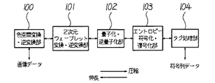
図1は、JPEG2000アルゴリズムの概要を説明するための機能ブロック図である。JPEG2000のアルゴリズムは、色空間変換・逆変換部100、2次元ウェーブレット変換・逆変換部101、量子化・逆量子化部102、エントロピー符号化・復号化部103、タグ処理部104で構成されている。
【0057】
JPEG2000の特徴の一つは、高圧縮領域における画質が良いという長所を持つ2次元離散ウェーブレット変換(DWT:Discrete Wavelet Transform)を用いている点である。また、もう一つの大きな特徴は、最終段に符号形成を行うためのタグ処理部104と呼ばれる機能ブロックが追加されており、符号列データであるコードストリームの生成や解釈が行われる点である。そして、コードストリームによって、JPEG2000は様々な便利な機能を実現できるようになっている。
【0058】
なお、画像の入出力部分には、色空間変換・逆変換部100が用意されることが多い。この色空間変換・逆変換部100は、例えば、原色系のR(赤)/G(緑)/B(青)の各コンポーネントからなるRGB表色系や、補色系のY(黄)/M(マゼンタ)/C(シアン)の各コンポーネントからなるYMC表色系から、YCrCbあるいはYUV表色系への変換又は逆の変換を行う部分である。
【0059】
以下、JPEG2000アルゴリズム、特にウェーブレット変換について説明する。
【0060】
図2は、カラー画像である原画像の分割された各コンポーネントの一例を概略的に示す模式図である。カラー画像は、一般に、図2に示すように、画像の各コンポーネント110が、例えばRGB原色系によって分離されている。さらに、画像の各コンポーネント110は、矩形をした領域であるタイル111によって分割されている。個々のタイル111、例えば、R00,R01,…,R15/G00,G01,…,G15/B00,B01,…,B15は、圧縮伸長プロセスを実行する際の基本単位を構成する。従って、圧縮伸長動作は、コンポーネント110毎に、そしてタイル111毎に、独立して行われる。
【0061】
画像データの符号化時には(図1参照)、各コンポーネント110の各タイル111のデータが色空間変換・逆変換部100に入力され、色空間変換を施された後、2次元ウェーブレット変換・逆変換部101で2次元ウェーブレット変換(順変換)が適用されて周波数帯に空間分割される。
【0062】
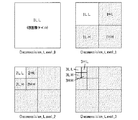
図3は、デコンポジションレベル数が3である場合の各デコンポジションレベルにおけるサブバンドを概略的に示す模式図である。2次元ウェーブレット変換・逆変換部101は、画像のタイル分割によって得られたタイル画像(デコンポジションレベル0:0LL)に対して、2次元ウェーブレット変換を施し、デコンポジションレベル1に示すサブバンド(1LL,1HL,1LH,1HH)を分離する。引き続き、2次元ウェーブレット変換・逆変換部101は、この階層における低周波成分1LLに対して、2次元ウェーブレット変換を施し、デコンポジションレベル2に示すサブバンド(2LL,2HL,2LH,2HH)を分離する。そして、2次元ウェーブレット変換・逆変換部101は、順次同様に、低周波成分2LLに対しても、2次元ウェーブレット変換を施し、デコンポジションレベル3に示すサブバンド(3LL,3HL,3LH,3HH)を分離する。なお、図3中では、各デコンポジションレベルにおいて符号化の対象となるサブバンドはグレーで示されている。例えば、デコンポジションレベル数を3とした場合、グレーで示したサブバンド(3HL,3LH,3HH,2HL,2LH,2HH,1HL,1LH,1HH)が符号化対象となり、3LLサブバンドは符号化されない。
【0063】
次いで、量子化・逆量子化部102では(図1参照)、指定した符号化の順番で符号化の対象となるビットが定められた後、対象ビット周辺のビットからコンテキストが生成される。量子化の処理が終わったウェーブレット係数は、個々のサブバンド毎に、「プレシンクト」と呼ばれる重複しない矩形に分割される。これは、インプリメンテーションでメモリを効率的に使うために導入されたものである。さらに、個々のプレシンクトは、重複しない矩形の「コードブロック」に分けられる。これは、エントロピーコーディングを行う際の基本単位となる。
【0064】
なお、ウェーブレット変換後の係数値は、そのまま量子化し符号化することも可能であるが、JPEG2000では符号化効率を上げるために、係数値を「ビットプレーン」単位に分解し、画素あるいはコードブロック毎にビットプレーンに順位付けを行うことができる。
【0065】
エントロピー符号化・復号化部103では(図1参照)、コンテキストと対象ビットとから、確率推定によって各コンポーネント110の各タイル111に対する符号化を行う。こうして、画像の全てのコンポーネント110について、タイル111単位で符号化処理が行われる。
【0066】
最後に、タグ処理部104では(図1参照)、エントロピー符号化・復号化部103からの全符号化データを1本のコードストリーム(符号列データ)に結合するとともに、それにタグを付加する処理を行う。ここで、図4は、コードストリームの構造の一例を概略的に示す模式図である。コードストリームの先頭と各タイル111を構成する部分タイルの先頭には、ヘッダ(メインヘッダ(Main header)、タイルパートヘッダ(tile part header))と呼ばれるタグ情報が付加され、その後に、各タイル111の符号化データ(bit stream)が続く。そして、コードストリームの終端には、再びタグ情報(end of codestream)が付加される。
【0067】
一方、復号化時には、符号化時とは逆に、各コンポーネント110の各タイル111のコードストリームから画像データを生成する。この場合、図1に示すように、タグ処理部104は、外部より入力されたコードストリーム(符号列データ)に付加されたタグ情報を解釈し、コードストリームを各コンポーネント110の各タイル111のコードストリームに分解し、その各コンポーネント110の各タイル111のコードストリーム毎に復号化処理を行う。この際、コードストリーム内のタグ情報に基づく順番で復号化の対象となるビットの位置が定められるとともに、量子化・逆量子化部102において、その対象ビット位置の周辺ビット(既に復号化を終えている)の並びからコンテキストを生成する。そして、エントロピー符号化・復号化部103では、そのコンテキストとコードストリームとから確率推定によって復号化を行って対象ビットを生成し、それを対象ビットの位置に書き込む。このようにして復号化されたデータは、周波数帯域毎に空間分割されているため、これを2次元ウェーブレット変換・逆変換部101で2次元ウェーブレット逆変換を行うことにより、画像データ中の各コンポーネント110における各タイル111が復元される。復元されたデータは、色空間変換・逆変換部100によって元の表色系のデータに変換される。
【0068】
次に、本実施の形態の画像処理装置である複合機1の構成例について説明する。本実施の形態の複合機1は、複写機能、プリンタ機能、スキャナ機能、ファクシミリ機能、画像サーバ機能等の複合機能を有している。
【0069】
図5は、本実施の形態の複合機1を概略的に示す縦断面図である。複合機1は、原稿から原稿画像を読み取る画像読取部であるスキャナ2と、スキャナ2で読み取られた画像を用紙等の記録材に形成する画像形成部であるプリンタ3とを備えている。
【0070】
スキャナ2の本体ケース4の上面には、原稿(図示せず)が載置されるコンタクトガラス5が設けられている。原稿は、原稿面をコンタクトガラス5に対向させて載置される。コンタクトガラス5の上側には、コンタクトガラス5上に載置された原稿を押える原稿圧板6(いわゆるADFであってもよい)が設けられている。
【0071】
コンタクトガラス5の下方には、原稿画像を光学的に読み取るための読取光学系7が設けられている。この読取光学系7は、光を発光する光源8及びミラー9を搭載する第1走行体10、2枚のミラー11,12を搭載する第2走行体13、結像レンズ14を介してミラー9,11,12によって導かれる光を受光するCCD(Charge Coupled Device)イメージセンサ15等によって構成されている。CCDイメージセンサ15は、CCDイメージセンサ15上に結像される原稿からの反射光を光電変換することで光電変換データを生成する光電変換素子として機能する。光電変換データは、原稿からの反射光の強弱に応じた大きさを有する電圧値である。第1、第2走行体10,13は、コンタクトガラス5に沿って往復動自在に設けられており、後述する原稿画像の読取動作に際しては、図示しないモータ等の移動装置によって2:1の速度比で副走査方向にスキャニング走行する。これにより、読取光学系7による原稿読取領域の露光走査が行われる。なお、本実施の形態では、読取光学系7側がスキャニング走査を行う原稿固定型で示しているが、読取光学系7側が位置固定で原稿側が移動する原稿移動型であっても良い。
【0072】
プリンタ3は、シート状の用紙等の記録材を保持する記録材保持部16から電子写真方式のプリンタエンジン17及び定着器18を経由して排出部19へ至る記録材経路20を備えている。
【0073】
プリンタエンジン17は、感光体21、帯電器22、露光器23、現像器24、転写器25及びクリーナー26等を用いて、電子写真方式で感光体21の周囲に形成したトナー像を記録材に転写し、転写したトナー像を、定着器18によって記録材上に定着させる。なお、本実施の形態では、プリンタエンジン17が電子写真方式で画像形成を行うが、これに限るものではなく、例えば、インクジェット方式、昇華型熱転写方式、直接感熱記録方式等の様々な画像形成方式で画像形成を行うようにしても良い。
【0074】
このような複合機1は、複数のマイクロコンピュータで構成される制御系により制御される。図6はこれらの制御系のうち、画像処理に関わる制御系の電気的な接続を概略的に示すブロック図である。この制御系は、CPU30、ROM31、RAM32、操作パネル33、IPU(Image Processing Unit)34、I/Oポート35、通信制御部36等がバス37で接続され構成されている。CPU30は、各種演算を行い、画像処理等の処理を集中的に制御する。ROM31には、CPU30が実行する処理に関わる各種プログラムや固定データが格納されている。また、RAM32は、CPU30のワークエリアとして機能し、加えて、画像データ(例えば、画像ファイル)を一時的に記憶するメモリとして機能する。操作パネル33には、LCD(Liquid Crystal Display)等の表示器、ハードキー及びタッチパネル等によって構成される複数の操作キー(いずれも図示せず)が設けられており、操作パネル33が表示部及び操作部として機能する。IPU34は各種画像処理に関わるハードウエアを備えており、ROM31はEEPROMやフラッシュメモリ等の不揮発性メモリを備えており、画像データ(例えば、画像ファイル)を記憶するメモリとしても機能する。ここで、ROM31内に格納されているプログラムは、CPU30の制御によりI/Oポート35を介して外部装置(図示せず)からダウンロードされるプログラムに書換え可能である。なお、本実施の形態では、ROM31がプログラムを記憶する記憶媒体として機能している。通信制御部36は、複合機1と外部装置(図示せず)との間でネットワーク等を介してデータを送受信する機能を有しており、ファクシミリのモデム機能、公衆電話回線網に接続するための網制御機能、LAN(Local Area Network)制御機能等を備えている。
【0075】
次に、本実施の形態の複合機1における画像処理の概要について図7を参照して説明する。図7は、複合機1における画像処理の概要を説明するための機能ブロック図である。
【0076】
複合機1の画像処理は、図1を参照して説明した各機能ブロックで構成されている圧縮部40と、各々複数の領域に分割され圧縮された第1の画像及び第2の画像から各々複数の領域毎に特徴量を抽出する特徴量抽出部41と、抽出した複数の領域毎の特徴量に基づいて第1の画像と第2の画像とを比較する画像比較部42と、を備えている。
【0077】
基本的には、スキャナ2で読み取られた画像の画像データをJPEG2000アルゴリズムに基づいて圧縮符号化し、画像のコードストリームを生成する。すなわち、画像を1又は複数の領域である複数のタイル領域(矩形領域)に分割し、このタイル領域毎に画素値を離散ウェーブレット変換して階層的に圧縮符号化する。その後、圧縮した画像からタイル領域毎に特徴量を抽出し、抽出した特徴量に基づいて、原画像(第1の画像)と他の画像(第2の画像)とを比較する。これにより、原画像の類似画像や原画像と一致する同一画像を検索したり、それらの画像を分類したりすることができる。ここで、複数の領域とは、タイル領域に限るものではない。なお、JPEG2000アルゴリズムに基づいて圧縮された画像データを受信して、受信した画像に対して特徴量抽出部41及び画像比較部42による処理を実行するようにしても良い。
【0078】
このような圧縮部40、特徴量抽出部41や画像比較部42等の機能は、ROM31に記憶されているプログラムに基づいてCPU30が行う画像処理で実行されるようにしているが、これに限るものではなく、例えば、IPU34によりハードウエアが行う画像処理で実行されるようにしても良い。
【0079】
ここで、特徴量抽出部41における特徴量の抽出方法について説明する。特徴量抽出部41では、複数の領域であるタイル領域毎に領域属性を識別する領域識別処理を実行し、領域属性を特徴量として抽出する。この領域属性としては、例えば、文字領域、写真領域、図領域、表領域、黒ベタ領域、背景領域、識別不能領域等の様々な領域属性がある。なお、識別不能領域とは、領域識別処理により領域属性を識別できなかった領域である。また、背景領域とは、原稿の余白にあたる余白領域であるが、これに限るものではなく、例えば、行間にあたる行間領域を余白領域に加えた領域であっても良い。
【0080】
次いで、複合機1のCPU30がプログラムに基づいて実行する画像処理について説明する。ここでは、複合機1を画像サーバとして用いるために画像データを蓄積する場合の画像処理について図8ないし図13を参照して説明する。図8は本実施の形態の画像処理の流れを概略的に示すフローチャート、図9は複数のタイル領域に分割された画像の一例を概略的に示す説明図、図10は特徴量抽出処理の流れを概略的に示すフローチャート、図11は画像比較処理の流れを概略的に示すフローチャート、図12は画像比較処理を概略的に示す説明図、図13は画像比較処理の結果を概略的に示す説明図である。
【0081】
図8に示すように、まず、スキャナ2による原稿画像の読取に待機する(ステップS1のN)。操作者がスキャナ2の原稿圧板6を開放してコンタクトガラス5上に原稿をセットし、原稿圧板6を閉じて操作パネル33のスタートキーを押下すると、スキャナ2は読取光学系7のスキャニング動作でコンタクトガラス5上にセットされた原稿から原画像(第1の画像)を読み取る。
【0082】
スキャナ2により原稿から原画像が読み取られると(S1のY)、読み取った原画像をJPEG2000アルゴリズムに基づいて圧縮する(S2)。すなわち、原画像は、複数のタイル領域に分割され、複数のタイル領域毎に2次元ウェーブレット変換、量子化及び符号化という手順で階層的に圧縮される。これにより、原画像は、複数のタイル領域に分割されることになる。例えば、図9に示すように、原画像は、4×6=24の複数のタイル領域に分割される。
【0083】
圧縮した原画像からタイル領域毎に特徴量を抽出する特徴量抽出処理を実行する(S3)。ここに、特徴量抽出手段又は特徴量抽出機能が実行される。ここでは、圧縮した原画像に対してタイル領域毎に領域属性を識別する領域識別処理を実行し、タイル領域毎に領域属性を特徴量として抽出する。
【0084】
ここで、特徴量抽出処理について説明する。図10に示すように、圧縮した原画像における全てのタイル領域の中から一つのタイル領域を選択する(S11)。選択したタイル領域に対して領域識別処理を実行して、タイル領域の領域属性を特徴量として抽出する(S12)。なお、領域識別処理の方法は、従来の方法、例えば、黒ランの密度を用いて領域識別する方法等で十分であり、その方法は公知であるため、その説明は省略する。そして、全てのタイル領域の領域属性が抽出されるまで、ステップS11からステップS12を繰り返す(S13のN)。これにより、全てのタイル領域の領域属性が、文字領域、写真領域、図領域、表領域、背景領域、識別不能領域等に識別され、タイル領域毎に抽出される。
【0085】
次に、図8に示すように、画像(画像データ)がROM31に保存されているか否かを判断する(S4)。画像がROM31に保存されていないと判断した場合には(S4のN)、圧縮した原画像(画像データ)をROM31(EEPROMやフラッシュメモリ等)に保存する(S5)。なお、ステップS3で、抽出された特徴量である領域属性は、原画像の画像データ中に保存されているが、これに限るものではなく、例えば、原画像に関連付られ領域属性データとして保存されても良い。
【0086】
画像がROM31に保存されていると判断した場合には(S4のY)、ステップS3でタイル領域毎に抽出された領域属性に基づいて、ステップS2で圧縮した原画像をROM31に保存されている画像(第2の画像)と比較する画像比較処理を実行する(S6)。ここに、画像比較手段又は画像比較機能が実行される。
【0087】
ここで、画像比較処理について説明する。図11に示すように、各々全てのタイル領域の中から1つのタイル領域を選択し(S21:図12参照)、選択した各々のタイル領域の領域属性を比較する(S22:図12参照)。ここに、特徴量比較手段又は特徴量比較機能が実行される。例えば、図12中では、画像Aと画像Bとにおいて、番号1で示すタイル領域の領域属性を比較している。このように、選択した各々タイル領域は、画像中の同一位置に位置するタイル領域である。次に、全てのタイル領域の領域属性が比較されるまで、ステップS21からステップS22を繰り返す(S23のN)。これにより、タイル領域毎に領域属性が比較され、タイル領域の領域属性が一致するか否かが判断される(図13参照)。なお、図13中では、〇が領域属性の一致を示し、×は領域属性が不一致を示す。
【0088】
このように全てのタイル領域の領域属性が比較され、その後、一致数すなわち〇の数を所定の一致数と比較する。ここに、一致数比較手段又は一致数比較機能が実行される。〇の数が所定の一致数より大きいと判断された場合には、圧縮した原画像とROM31に保存されている画像とを一致度が高い画像(類似画像や同一画像等)として特定する。ここに、画像特定手段又は画像特定機能が実行される。例えば、図12中では、所定の一致数を20と設定しておき、〇の数が20より大きい又は20以上である場合、圧縮した原画像とROM31に保存されている画像とを類似画像として特定したり、所定の一致数を24と設定しておき、〇の数が24である場合、圧縮した原画像とROM31に保存されている画像とを同一画像として特定したりする。なお、所定の一致数は、複合機1の工場出荷前に設定されているが、これに限るものではなく、例えば操作パネル33に対する操作者の操作によって設定されるようにしても良い。
【0089】
その後、図8に示すように、圧縮した原画像(画像データ)を一致度が高い画像と関連付けてROM31(EEPROMやフラッシュメモリ等)に保存する(S5)。なお、一致度が高い画像が存在しない場合には、関連付けを行わずに原画像をROM31に保存する。ここで、複数の原画像が読み取られると、複数の画像は、特徴量である領域属性に基づいて分類され、類似画像又は同一画像毎に関連付けられてROM31に保存される。これにより、分類された複数の画像で構成された画像ファイル(辞書ファイル)が形成されることになる。なお、JPEG2000アルゴリズムに基づいて圧縮された画像を通信制御部36により受信して、受信した画像に対してステップS3からステップS6までの画像処理を実行するようにしても良い。
【0090】
このようにROM31に保存された画像は、例えば、JPEG2000アルゴリズムに基づいて伸長され、プリンタエンジン17によって用紙等の記録材に画像形成されたり、通信制御部36によってネットワーク等を介して外部装置に送信されたりする。ここに、伸長手段又は伸長機能が実行される。
【0091】
また、操作パネル33に対する操作者の操作によって選択された画像に関して類似画像や同一画像等を検索する場合にも、前述した画像処理が同様に実行される。これにより、一致度が高い画像が検索され、類似画像や同一画像等が求められる。
【0092】
このように本実施の形態では、JPEG2000アルゴリズムに基づいて圧縮された原画像(第1の画像)とROM31に保存されている画像(第2の画像)とから各々タイル領域毎にタイル領域の領域属性を識別し、識別したタイル領域の領域属性を特徴量として抽出し(S3)、抽出したタイル領域毎の領域属性に基づいて原画像とROM31に保存されている画像とを比較するようにしたことから、JPEG2000の特徴を活かした様々な画像処理を実行することが可能になり、画像を複数の領域に分割する処理や複数の解像度の画像を形成する処理等が必要とされず、簡単な処理で精度良く画像比較を実行することが可能となり、その結果として、システム規模の縮小及び処理時間の短縮を実現することができる。
【0093】
また、全てのタイル領域の領域属性を抽出し、全てのタイル領域の領域属性を比較することで、一部分のタイル領域の領域属性を比較する場合に比べ、精度高く画像比較を実行することができる。
【0094】
ここで、ステップS12における領域属性の識別方法としては、従来の識別方法以外に、ウェーブレット特徴量を用いることも可能であり、例えば、画像をタイル領域毎に2次元ウェーブレット変換し(図3参照)、タイル領域の2次元ウェーブレット係数中に含まれている周波数成分情報(LL成分、LH成分、HL成分、HH成分)に基づいてタイル領域の領域属性を識別する方法がある。なお、LL成分とは水平方向低周波・垂直方向低周波成分であり、LH成分とは水平方向低周波・垂直方向高周波成分であり、HL成分とは水平方向高周波・垂直方向低周波成分であり、HH成分とは水平方向高周波・垂直方向高周波成分である。また、JPEG2000の2次元ウェーブレット変換は、1次元フィルタを水平方向及び垂直方向に適用することで2次元ウェーブレット係数を算出し、算出した2次元ウェーブレット係数をローパスフィルタとハイパスフィルタとの組合せによって、前述した4つの係数群(LL成分、LH成分、HL成分、HH成分)に分割する。
【0095】
このような周波数成分情報に基づく領域属性の識別方法においては、画像の写真領域でHH成分が高くなることを利用して、HH成分の領域が広く分布しているタイル領域の領域属性を写真領域属性として識別する。また、画像の文字領域でHH成分が文字行方向に隣設して連続することを利用して、HH成分が文字行方向に隣設して連続するタイル領域の領域属性を文字領域属性として識別する。さらに、表の罫線がHL成分及びLH成分に反応することを利用して、HL及びLH成分に基づいて罫線情報である罫線の交差情報を抽出し、抽出した罫線の交差情報からタイル領域の領域属性を表領域属性として識別する。加えて、背景領域でLL成分以外のHH、HL、LH成分があまり高くないことを利用して、HH、HL、LH成分が他の領域に比べあまり高くないタイル領域の領域属性を背景領域属性として識別する。また、HL及びLH成分に基づいて罫線情報である罫線の傾き情報(傾き量)を抽出し、抽出した罫線の傾き情報から画像の傾きを求め、傾き角度を検出することも可能である。
【0096】
このように周波数成分情報を用いることで、従来の領域識別方法に比べ、精度高く領域識別を実行することができる。さらに、従来、エッジ情報を求めてから罫線情報を抽出していたが、圧縮された画像が有しているエッジ情報のHL成分及びLH成分の周波数成分情報を用いることで、エッジ情報を求める必要が無いので、システム規模の縮小及び処理時間の短縮を実現することができる。
【0097】
本発明の第二の実施の形態について説明する。本実施の形態は、第一の実施の形態と基本的構成は同じであり、その相違点は、複合機1のCPU30がプログラムに基づいて実行する特徴量抽出処理であり、特に、操作パネル33に対する操作者の操作によって選択された必要領域に基づいて、特徴量を抽出する必要があるタイル領域を指定する点である。なお、第一の実施の形態で説明した部分と同一部分は同一符号で示し、その説明も省略する。
【0098】
本実施の形態における複合機1のCPU30がプログラムに基づいて実行する画像処理の一部である特徴量抽出処理について図14及び図15を参照して説明する。図14は本実施の形態の特徴量抽出処理の流れを概略的に示すフローチャート、図15は必要領域の一例を概略的に示す説明図である。
【0099】
図14に示すように、操作パネル33に対する操作者の操作によって選択された必要領域に基づいて、特徴量である領域属性を抽出する必要があるタイル領域を指定する(S31)。ここに、領域指定手段又は領域指定機能が実行される。ここで、原画像には、タイル領域毎に1から24までの番号が割り当てられている(図15参照)。例えば、操作者が操作パネル33を操作して9から20までの番号を選択することで、9から20までの複数のタイル領域が必要領域として選択される(図15参照)。なお、必要領域が選択されなかった場合には、例えば、1から24までの全てのタイル領域が必要領域として選択される。
【0100】
指定された複数のタイル領域の中から一つのタイル領域を選択する(S32)。選択したタイル領域に対して領域識別処理を実行して、タイル領域の領域属性を特徴量として抽出する(S33)。指定された複数のタイル領域の領域属性が抽出されるまで、ステップS32からステップS33を繰り返す(S34のN)。これにより、全てのタイル領域の領域属性が、文字領域、写真領域、図領域、表領域、背景領域、識別不能領域等に識別され、タイル領域毎に抽出される。
【0101】
このように本実施の形態では、第一の実施の形態の効果と同様な効果が得られ、さらに、操作パネル33に対する操作者の操作によって、領域属性を抽出する必要があるタイル領域が指定されることから、その指定されたタイル領域に対してのみ領域識別処理が実行されるので、全てのタイル領域に対して領域識別処理を実行する場合に比べて、処理時間を短縮することができる。
【0102】
なお、各実施の形態においては、画像処理装置として複合機1を用いているが、これに限るものではなく、例えば、パーソナルコンピュータ等を用いても良い。この場合、パーソナルコンピュータは、CPU、ROM、RAM、各種のプログラムを記憶するHDD(Hard Disk Drive)、CD−ROMドライブ、ネットワークを介し外部装置と通信により情報を伝達するための通信制御装置、処理経過や結果等を操作者に表示する表示装置、キーボードやマウス等の入力装置等を備えている。ここで、HDDは、前述したようなJPEG2000フォーマットの圧縮伸長用のプログラムを含むプログラムを記憶する記憶媒体として機能する。
【0103】
なお、一般的には、パーソナルコンピュータのHDDにインストールされるプログラムは、CD−ROMやDVD−ROM等の光情報記録メディアやFD等の磁気メディア等に記録され、この記録されたプログラムがHDDにインストールされる。このため、CD−ROM等の光情報記録メディアやFD等の磁気メディア等の可搬性を有する記憶媒体も、前述したようなJPEG2000フォーマットの圧縮伸長用のプログラムを含むプログラムを記憶する記憶媒体となり得る。さらには、このようなプログラムは、例えば通信制御装置を介して外部から取込まれ、HDDにインストールされても良い。
【0104】
【発明の効果】
請求項1記載の発明の画像処理装置によれば、各々複数の領域に分割され圧縮された第1の画像と第2の画像とから各々複数の領域毎に特徴量を抽出する特徴量抽出手段と、前記特徴量抽出手段により前記第1の画像と前記第2の画像とから各々複数の領域毎に抽出された特徴量に基づいて、前記第1の画像と前記第2の画像とを比較する画像比較手段と、を備えることから、画像を複数の領域に分割する処理等が必要とされず、簡単な処理で精度良く画像比較を実行することが可能となり、その結果として、システム規模の縮小及び処理時間の短縮を実現することができる。
【0105】
請求項2記載の発明によれば、請求項1記載の画像処理装置において、前記特徴量抽出手段は、領域の領域属性を識別し、識別した領域属性を特徴量として抽出することから、簡単に特徴量を抽出することができ、精度高く画像比較を実行することができる。
【0106】
請求項3記載の発明によれば、請求項2記載の画像処理装置において、前記第1の画像及び前記第2の画像は、複数の領域毎に2次元ウェーブレット変換、量子化及び符号化という手順で圧縮されており、前記特徴量抽出手段は、領域の2次元ウェーブレット係数中に含まれている周波数成分情報に基づいて領域の領域属性を識別することから、特徴量を抽出するための処理が簡略化され、精度高く簡単に領域属性を識別することが可能となり、その結果として、処理時間の短縮を実現することができる。
【0107】
請求項4記載の発明によれば、請求項3記載の画像処理装置において、前記特徴量抽出手段は、領域の2次元ウェーブレット係数中に含まれているHL成分及びLH成分に基づいてタイル領域の領域属性を表領域属性として識別することから、精度高く簡単に表領域を識別することができる。
【0108】
請求項5記載の発明によれば、請求項1記載の画像処理装置において、前記特徴量抽出手段は、領域の2次元ウェーブレット係数中に含まれているHL成分及びLH成分に基づいて罫線情報を特徴量として抽出することから、精度高く簡単に画像の罫線情報を抽出することができる。
【0109】
請求項6記載の発明によれば、請求項1ないし5のいずれか一記載の画像処理装置において、操作者による操作を受け付ける操作部と、前記操作部に対する操作者の操作に基づいて、特徴量を抽出する必要がある領域を指定する領域指定手段と、を備え、前記特徴量抽出手段は、前記領域指定手段により指定された領域だけの特徴量を抽出することから、操作部に対する操作者の操作によって、特徴量を抽出する必要がある領域が指定されることで、その指定された領域からのみ特徴量が抽出されるので、全ての領域から特徴量を抽出する場合に比べ、処理時間を短縮することができる。
【0110】
請求項7記載の発明によれば、請求項1ないし6のいずれか一記載の画像処理装置において、前記画像比較手段は、前記特徴量抽出手段により前記第1の画像と前記第2の画像とから各々複数の領域毎に抽出された特徴量を複数の領域毎に比較する特徴量比較手段と、前記特徴量比較手段による前記第1の画像の特徴量と前記第2の画像の特徴量との一致数を所定の一致数と比較する一致数比較手段と、前記一致数比較手段により前記一致数が所定の一致数より大きいと判断された場合、前記第1の画像と前記第2の画像とを一致度が高い画像として特定する画像特定手段と、を備えることから、第1の画像と第2の画像とから各々複数の領域毎に抽出された特徴量を複数の領域毎に比較することで、精度高く簡単に画像比較を実行することができる。
【0111】
請求項8記載の発明によれば、請求項7記載の画像処理装置において、前記特徴量抽出手段は、全ての領域の特徴量を抽出し、前記特徴量比較手段は、全ての領域の特徴量を比較することから、一部分の領域の特徴量を比較する場合に比べ、精度高く画像比較を実行することができる。
【0112】
請求項9記載の発明によれば、請求項1ないし8のいずれか一記載の画像処理装置において、原稿から画像を光学的に読み取る読取光学系を備えることから、原稿から画像を読み取ることが可能になり、その結果として、この画像に対し画像処理等の様々な処理を実行することができる。
【0113】
請求項10記載の発明によれば、請求項1ないし9のいずれか一記載の画像処理装置において、圧縮された画像を複数の領域毎に復号化、逆量子化及び2次元ウェーブレット逆変換という手順で伸長する伸長手段を備えることから、圧縮された画像が伸長され、その結果として、伸長された画像の表示装置等への表示や用紙等への印字等を実行することができる。
【0114】
請求項11記載の発明によれば、請求項10記載の画像処理装置において、前記伸長手段により伸長された画像を記録材に画像形成するプリンタエンジンを備えることから、伸長された画像を用紙等の記録材に画像形成することができる。
【0115】
請求項12記載の発明のプログラムによれば、画像処理装置が備えるコンピュータに解釈され、前記コンピュータに、各々複数の領域に分割され圧縮された第1の画像と第2の画像とから各々複数の領域毎に特徴量を抽出する特徴量抽出機能と、前記特徴量抽出機能により前記第1の画像と前記第2の画像とから各々複数の領域毎に抽出された特徴量に基づいて、前記第1の画像と前記第2の画像とを比較する画像比較機能と、を実行させることから、画像を複数の領域に分割する処理等が必要とされず、簡単な処理で精度良く画像比較を実行することが可能となり、その結果として、システム規模の縮小及び処理時間の短縮を実現することができる。
【0116】
請求項13記載の発明によれば、請求項12記載のプログラムにおいて、前記特徴量抽出機能は、領域の領域属性を識別し、識別した領域属性を特徴量として抽出することから、簡単に特徴量を抽出することができ、精度高く画像比較を実行することができる。
【0117】
請求項14記載の発明によれば、請求項13記載のプログラムにおいて、前記第1の画像及び前記第2の画像は、複数の領域毎に2次元ウェーブレット変換、量子化及び符号化という手順で圧縮されており、前記特徴量抽出機能は、領域の2次元ウェーブレット係数中に含まれている周波数成分情報に基づいて領域の域の領域属性を識別することから、特徴量を抽出するための処理が簡略化され、精度高く簡単に領域属性を識別することが可能となり、その結果として、処理時間の短縮を実現することができる。
【0118】
請求項15記載の発明によれば、請求項14記載のプログラムにおいて、前記特徴量抽出機能は、領域の2次元ウェーブレット係数中に含まれているHL成分及びLH成分に基づいてタイル領域の領域属性を表領域属性として識別することから、精度高く簡単に表領域を識別することができる。
【0119】
請求項16記載の発明によれば、請求項12記載のプログラムにおいて、前記特徴量抽出機能は、領域の2次元ウェーブレット係数中に含まれているHL成分及びLH成分に基づいて罫線情報を特徴量として抽出することから、精度高く簡単に画像の罫線情報を抽出することができる。
【0120】
請求項17記載の発明によれば、請求項12ないし16のいずれか一記載のプログラムにおいて、操作部に対する操作者の操作に基づいて、特徴量を抽出する必要がある領域を指定する領域指定機能を前記コンピュータに実行させ、前記特徴量抽出機能は、前記領域指定機能により指定された領域だけの特徴量を抽出することから、操作部に対する操作者の操作によって、特徴量を抽出する必要がある領域が指定されることで、その指定された領域からのみ特徴量が抽出されるので、全ての領域から特徴量を抽出する場合に比べ、処理時間を短縮することができる。
【0121】
請求項18記載の発明によれば、請求項12ないし17のいずれか一記載のプログラムにおいて、前記画像比較機能は、前記特徴量抽出機能により前記第1の画像と前記第2の画像とから各々複数の領域毎に抽出された特徴量を複数の領域毎に比較する特徴量比較機能と、前記特徴量比較機能による前記第1の画像の特徴量と前記第2の画像の特徴量との一致数を所定の一致数と比較する一致数比較機能と、前記一致数比較機能により前記一致数が所定の一致数より大きいと判断された場合、前記第1の画像と前記第2の画像とを一致度が高い画像として特定する画像特定機能と、を前記コンピュータに実行させることから、第1の画像と第2の画像とから各々複数の領域毎に抽出された特徴量を複数の領域毎に比較することで、精度高く簡単に画像比較を実行することができる。
【0122】
請求項19記載の発明によれば、請求項18記載のプログラムにおいて、前記特徴量抽出機能は、全ての領域の特徴量を抽出し、前記特徴量比較機能は、全ての領域の特徴量を比較することから、一部分の領域の特徴量を比較する場合に比べ、精度高く画像比較を実行することができる。
【0123】
請求項20記載の発明によれば、請求項12ないし19のいずれか一記載のプログラムにおいて、圧縮された画像を複数の領域毎に復号化、逆量子化及び2次元ウェーブレット逆変換という手順で伸長する伸長機能を前記コンピュータに実行させることから、圧縮された画像が伸長され、その結果として、伸長された画像の表示装置等への表示や用紙等への印字等を実行することができる。
【0124】
請求項21記載の発明のコンピュータ読取可能な記憶媒体によれば、請求項12ないし20のいずれか一記載のプログラムを記憶していることから、請求項12ないし20のいずれか一記載の発明と同様な効果を奏する。
【図面の簡単な説明】
【図1】JPEG2000アルゴリズムの概要を説明するための機能ブロック図である。
【図2】カラー画像である原画像の分割された各コンポーネントの一例を概略的に示す模式図である。
【図3】デコンポジションレベル数が3である場合の各デコンポジションレベルにおけるサブバンドを概略的に示す模式図である。
【図4】コードストリームの構造の一例を概略的に示す模式図である。
【図5】本発明の第一の実施の形態の複合機を概略的に示す縦断面図である。
【図6】複合機の制御系のうち、画像処理に関わる制御系の電気的な接続を概略的に示すブロック図である。
【図7】複合機における画像処理の概要を説明するための機能ブロック図である。
【図8】本発明の第一の実施の形態の画像処理の流れを概略的に示すフローチャートである。
【図9】複数のタイル領域に分割された画像の一例を概略的に示す説明図である。
【図10】本発明の第一の実施の形態の特徴量抽出処理の流れを概略的に示すフローチャートである。
【図11】画像比較処理の流れを概略的に示すフローチャートである。
【図12】画像比較処理を概略的に示す説明図である。
【図13】画像比較処理の結果を概略的に示す説明図である。
【図14】本発明の第二の実施の形態の特徴量抽出処理の流れを概略的に示すフローチャートである。
【図15】必要領域の一例を概略的に示す説明図である。
【符号の説明】
1 画像処理装置(複合機)
7 読取光学系
17 プリンタエンジン
31 記憶媒体(ROM)
33 操作部(操作パネル)[0001]
TECHNICAL FIELD OF THE INVENTION
The present invention relates to an image processing device, a program, and a storage medium.
[0002]
[Prior art]
2. Description of the Related Art In recent years, with the spread of image processing apparatuses such as scanners, digital cameras, computers, copiers, and multifunction peripherals (MFPs), digital image data is stored in a storage device such as a memory or a hard disk, or is stored on an optical disk such as a CD-ROM. It is familiar to memorize and further transmit via the Internet or the like. In particular, recently, computers, multifunction devices, and the like are often used as image servers. Various image processing is performed on such image data.
[0003]
For example, as a general image processing flow for a multifunction device or the like,
(1) Image input → tilt angle detection → tilt angle correction → area identification processing → character recognition processing
▲ 2 ▼ Image input → Tilt angle detection → Tilt angle correction → Title extraction → Use title as file name for document management
(3) Color image input → binarization processing → inclination angle detection (same as the processing of (1) or (2) thereafter)
(4) Color image input → Binarization processing (same as the processing of (3)) → Specify the character color of the character area or title area → Reproduce and display
And so on.
[0004]
The flow of image processing for searching for images (or image processing for classifying images) is as follows.
(5) Image input → feature extraction → search for images with similar features (subsequent classification)
Such processing is common. Here, the feature amount includes color, texture, edge information, and the like.
[0005]
Various techniques executed in such a flow of image processing have been proposed. For example, a technique of storing image data of a plurality of resolutions and selectively outputting an image of a resolution suitable for an output device (for example, see Patent Document 1), generating image data of a plurality of resolutions, and creating a ruled line from the image of each resolution (See, for example, Patent Document 2), a technique of generating image data of a plurality of resolutions, obtaining an optimum resolution based on a character type, and then performing a character recognition process (see, for example, Patent Document 3) Etc. have been proposed.
[0006]
On the other hand, recently, high-definition images can be easily obtained by various techniques, but the data size of such high-definition still images tends to be large, and handling of high-definition still images becomes difficult. ing. At present, JPEG (Joint Photographic Experts Group) and JPEG2000, an image compression / expansion method succeeding JPEG, which became an international standard in 2001, are used as image compression / expansion algorithms for facilitating the handling of such high-definition still images. The feature of the image data compressed by JPEG2000 is that it has images of a plurality of resolutions, one image is previously divided into a plurality of regions (tile regions) by a tiling process, and a frequency component (LL) Component, LH component, HL component, HH component).
[0007]
[Patent Document 1]
JP 2000-187725 A
[Patent Document 2]
JP 2001-127772 A
[Patent Document 3]
JP-A-2002-24766
[0008]
[Problems to be solved by the invention]
Conventional techniques generate image data of a plurality of resolutions, store the generated image data of a plurality of resolutions, divide an image into a plurality of regions, and obtain edge information which is a feature amount. Need to be Since it is necessary to execute various processes as described above, the system scale of the image processing increases, and the processing time of the image processing also increases.
[0009]
Further, in the conventional technique, since the feature amount is often extracted from a part of the image, the image comparison is not performed with high accuracy when searching or classifying the image, and as a result, the image search or classification is performed accurately. May not be done.
[0010]
An object of the present invention is to provide an image processing apparatus, a program, and a storage medium that can realize a reduction in system scale and processing time.
[0011]
An object of the present invention is to provide an image processing device, a program, and a storage medium that can execute image comparison with high accuracy.
[0012]
[Means for Solving the Problems]
An image processing apparatus according to
[0013]
Therefore, a feature amount is extracted for each of the plurality of regions from the first image and the second image which are divided into a plurality of regions and compressed, and the first image and the second image are extracted based on the extracted feature amounts. By comparing the image with the image, processing for dividing the image into a plurality of regions is not required, and the image comparison can be performed with high accuracy by simple processing. As a result, the system scale is reduced and the processing is reduced. Time can be reduced.
[0014]
According to a second aspect of the present invention, in the image processing apparatus according to the first aspect, the feature amount extracting unit identifies a region attribute of the region and extracts the identified region attribute as a feature amount.
[0015]
Therefore, by identifying the region attribute of the region, the feature amount can be easily extracted, and the image comparison can be performed with high accuracy.
[0016]
According to a third aspect of the present invention, in the image processing apparatus of the second aspect, the first image and the second image are compressed by a procedure of two-dimensional wavelet transform, quantization, and encoding for each of a plurality of regions. The feature value extracting means identifies a region attribute of the region based on frequency component information included in a two-dimensional wavelet coefficient of the region.
[0017]
Therefore, by identifying the region attribute of the region based on the frequency component information included in the two-dimensional wavelet coefficient of the region, the process for extracting the feature amount is simplified, and the region attribute can be easily and accurately determined. The identification can be performed, and as a result, the processing time can be reduced.
[0018]
According to a fourth aspect of the present invention, in the image processing apparatus according to the third aspect, the feature amount extracting unit determines a region attribute of the tile region based on an HL component and an LH component included in a two-dimensional wavelet coefficient of the region. As a tablespace attribute.
[0019]
Therefore, by identifying the region attribute of the region as the table region attribute based on the HL component and the LH component included in the two-dimensional wavelet coefficient of the region, it is possible to easily and accurately identify the table region. .
[0020]
According to a fifth aspect of the present invention, in the image processing apparatus according to the first aspect, the feature amount extracting unit converts the ruled line information based on the HL component and the LH component included in the two-dimensional wavelet coefficient of the region. Extract as
[0021]
Therefore, by extracting the ruled line information based on the HL component and the LH component included in the two-dimensional wavelet coefficient of the area, it is possible to easily and accurately extract the ruled line information of the image.
[0022]
According to a sixth aspect of the present invention, in the image processing apparatus according to any one of the first to fifth aspects, an operation unit that receives an operation by an operator and a feature amount is extracted based on the operation of the operator on the operation unit. Area designating means for designating an area which needs to be performed, wherein the feature quantity extracting means extracts a feature quantity of only the area designated by the area designating means.
[0023]
Therefore, by specifying an area from which a feature amount needs to be extracted by an operation performed by the operator on the operation unit, the feature amount is extracted only from the specified area. The processing time can be shortened as compared with the case of performing the processing.
[0024]
According to a seventh aspect of the present invention, in the image processing apparatus according to any one of the first to sixth aspects, the image comparing unit is configured to determine each of the first image and the second image by the feature amount extracting unit. A feature amount comparing unit that compares a feature amount extracted for each of the plurality of regions for each of the plurality of regions, and matching between the feature amount of the first image and the feature amount of the second image by the feature amount comparing unit. A number-of-matches comparing means for comparing the number with a predetermined number of matches; and if the number of matches is determined by the number-of-matches comparing means to be greater than the predetermined number of matches, the first image and the second image are compared. Image specifying means for specifying an image having a high degree of coincidence.
[0025]
Therefore, by comparing the feature amount extracted for each of the plurality of regions from the first image and the second image for each of the plurality of regions, it is possible to easily and accurately perform the image comparison.
[0026]
According to an eighth aspect of the present invention, in the image processing apparatus according to the seventh aspect, the feature amount extracting unit extracts feature amounts of all the regions, and the feature amount comparing unit compares the feature amounts of all the regions. I do.
[0027]
Therefore, by comparing the feature values of all the regions, it is possible to perform the image comparison with higher accuracy than when comparing the feature values of a part of the regions.
[0028]
According to a ninth aspect of the present invention, in the image processing apparatus according to any one of the first to eighth aspects, a reading optical system for optically reading an image from a document is provided.
[0029]
Therefore, an image can be read from a document, and as a result, various processes such as image processing can be performed on the image.
[0030]
According to a tenth aspect of the present invention, in the image processing apparatus according to any one of the first to ninth aspects, the compressed image is decompressed for each of a plurality of regions, decompressed, and decompressed by two-dimensional wavelet inverse transform. Extending means for performing the extension.
[0031]
Therefore, the compressed image (code data) is expanded for each of a plurality of areas by decoding, inverse quantization, and inverse two-dimensional wavelet transform, whereby the compressed image is expanded. As a result, the expanded image is expanded. It is possible to execute the display of the displayed image on a display device or the like, the printing on paper or the like.
[0032]
According to an eleventh aspect of the present invention, in the image processing apparatus according to the tenth aspect, there is provided a printer engine for forming an image decompressed by the decompression means on a recording material.
[0033]
Therefore, it is possible to form an image of the expanded image on a recording material such as paper.
[0034]
The program according to
[0035]
Therefore, a feature amount is extracted for each of the plurality of regions from the first image and the second image which are divided into a plurality of regions and compressed, and the first image and the second image are extracted based on the extracted feature amounts. By comparing the image with the image, processing for dividing the image into a plurality of regions is not required, and the image comparison can be performed with high accuracy by simple processing. As a result, the system scale is reduced and the processing is reduced. Time can be reduced.
[0036]
According to a thirteenth aspect of the present invention, in the program according to the twelfth aspect, the feature amount extracting function identifies a region attribute of the region and extracts the identified region attribute as a feature amount.
[0037]
Therefore, by identifying the region attribute of the region, the feature amount can be easily extracted, and the image comparison can be performed with high accuracy.
[0038]
According to a fourteenth aspect of the present invention, in the program according to the thirteenth aspect, the first image and the second image are compressed by a procedure of two-dimensional wavelet transform, quantization, and encoding for each of a plurality of regions. The feature extraction function identifies a region attribute of a region based on frequency component information included in a two-dimensional wavelet coefficient of the region.
[0039]
Therefore, by identifying the region attribute of the region based on the frequency component information included in the two-dimensional wavelet coefficient of the region, the process for extracting the feature amount is simplified, and the region attribute can be easily and accurately determined. The identification can be performed, and as a result, the processing time can be reduced.
[0040]
According to a fifteenth aspect of the present invention, in the program according to the fourteenth aspect, the feature amount extracting function displays an area attribute of the tile area based on an HL component and an LH component included in a two-dimensional wavelet coefficient of the area. Identify as an area attribute.
[0041]
Therefore, by identifying the region attribute of the region as the table region attribute based on the HL component and the LH component included in the two-dimensional wavelet coefficient of the region, it is possible to easily and accurately identify the table region. .
[0042]
According to a sixteenth aspect of the present invention, in the program according to the twelfth aspect, the feature amount extracting function extracts ruled line information as a feature amount based on HL components and LH components included in a two-dimensional wavelet coefficient of the area. I do.
[0043]
Therefore, by extracting the ruled line information based on the HL component and the LH component included in the two-dimensional wavelet coefficient of the area, it is possible to easily and accurately extract the ruled line information of the image.
[0044]
According to a seventeenth aspect of the present invention, in the program according to any one of the twelfth to thirteenth aspects, the program has an area designating function for designating an area in which a feature amount needs to be extracted based on an operation performed by an operator on an operation unit. The program is executed by a computer, and the feature amount extracting function extracts a feature amount of only an area specified by the area specifying function.
[0045]
Therefore, by specifying an area for which a feature amount needs to be extracted by an operation on the operation unit, the feature amount is extracted only from the specified area, and the feature amount is extracted from all the areas. The processing time can be shortened as compared with the case of performing the processing.
[0046]
The invention according to
[0047]
Therefore, by comparing the feature amount extracted for each of the plurality of regions from the first image and the second image for each of the plurality of regions, it is possible to easily and accurately perform the image comparison.
[0048]
According to a nineteenth aspect of the present invention, in the program according to the eighteenth aspect, the feature amount extracting function extracts feature amounts of all the regions, and the feature amount comparing function compares the feature amounts of all the regions.
[0049]
Therefore, by comparing the feature values of all the regions, it is possible to perform the image comparison with higher accuracy than when comparing the feature values of a part of the regions.
[0050]
According to a twentieth aspect of the present invention, there is provided the program according to any one of the twelfth to nineteenth aspects, wherein the compressed image is expanded for each of a plurality of regions by a procedure of decoding, inverse quantization, and inverse two-dimensional wavelet transform. Causing the computer to execute a function.
[0051]
Therefore, the compressed image (code data) is expanded by decoding, dequantization, and inverse two-dimensional wavelet transform for each of a plurality of regions, so that the compressed image is expanded. As a result, the expanded image is expanded. It is possible to execute the display of the displayed image on a display device or the like, the printing on paper or the like.
[0052]
A computer-readable storage medium according to a twenty-first aspect stores the program according to any one of the twelfth to twentieth aspects.
[0053]
Therefore, the same operation as the invention according to any one of
[0054]
BEST MODE FOR CARRYING OUT THE INVENTION
A first embodiment of the present invention will be described with reference to FIGS.
[0055]
In the present embodiment, the “JPEG2000 algorithm” is used. However, since the JPEG2000 algorithm itself is well known in various documents and gazettes, the details are omitted, and the outline is described.
[0056]
FIG. 1 is a functional block diagram for explaining the outline of the JPEG2000 algorithm. The JPEG2000 algorithm includes a color space conversion /
[0057]
One of the features of JPEG2000 is that a two-dimensional discrete wavelet transform (DWT: Discrete Wavelet Transform) having an advantage of high image quality in a high compression area is used. Another major feature is that a functional block called a
[0058]
Note that a color space conversion /
[0059]
Hereinafter, the JPEG2000 algorithm, particularly the wavelet transform, will be described.
[0060]
FIG. 2 is a schematic diagram schematically illustrating an example of each of the divided components of an original image that is a color image. In a color image, as shown in FIG. 2, each
[0061]
At the time of encoding image data (see FIG. 1), data of each tile 111 of each
[0062]
FIG. 3 is a schematic diagram schematically showing subbands at each decomposition level when the number of decomposition levels is three. The two-dimensional wavelet transform /
[0063]
Next, in the quantization / dequantization unit 102 (see FIG. 1), after bits to be encoded are determined in the specified encoding order, a context is generated from bits around the target bits. The wavelet coefficients after the quantization process are divided into non-overlapping rectangles called “precincts” for each subband. This was introduced to make efficient use of memory in the implementation. Furthermore, each precinct is divided into non-overlapping rectangular “code blocks”. This is a basic unit when performing entropy coding.
[0064]
Although the coefficient values after the wavelet transform can be quantized and encoded as they are, in JPEG2000, in order to increase the encoding efficiency, the coefficient values are decomposed into "bit planes", and each pixel or code block is decomposed. The bit planes can be prioritized.
[0065]
The entropy coding / decoding unit 103 (see FIG. 1) performs coding on each tile 111 of each
[0066]
Finally, the tag processing unit 104 (see FIG. 1) combines all coded data from the entropy coding /
[0067]
On the other hand, at the time of decoding, image data is generated from the code stream of each tile 111 of each
[0068]
Next, a configuration example of the multifunction peripheral 1 which is the image processing apparatus of the present embodiment will be described. The
[0069]
FIG. 5 is a longitudinal sectional view schematically showing the multifunction peripheral 1 of the present embodiment. The
[0070]
A
[0071]
Below the
[0072]
The
[0073]
The
[0074]
The
[0075]
Next, an outline of image processing in the multifunction peripheral 1 of the present embodiment will be described with reference to FIG. FIG. 7 is a functional block diagram for explaining an outline of image processing in the multifunction peripheral 1.
[0076]
The image processing of the
[0077]
Basically, image data of an image read by the
[0078]
The functions of the
[0079]
Here, a method of extracting a feature amount in the feature
[0080]
Next, image processing executed by the
[0081]
As shown in FIG. 8, first, the process waits for reading of a document image by the scanner 2 (N in step S1). When the operator opens the
[0082]
When an original image is read from a document by the scanner 2 (Y in S1), the read original image is compressed based on the JPEG2000 algorithm (S2). That is, the original image is divided into a plurality of tile areas, and is hierarchically compressed in a procedure of two-dimensional wavelet transform, quantization, and encoding for each of the plurality of tile areas. As a result, the original image is divided into a plurality of tile areas. For example, as shown in FIG. 9, the original image is divided into a plurality of 4 × 6 = 24 tile areas.
[0083]
A feature amount extraction process for extracting a feature amount for each tile region from the compressed original image is executed (S3). Here, a feature amount extracting means or a feature amount extracting function is executed. Here, region identification processing for identifying a region attribute for each tile region is performed on the compressed original image, and the region attribute is extracted as a feature amount for each tile region.
[0084]
Here, the feature amount extraction processing will be described. As shown in FIG. 10, one tile area is selected from all the tile areas in the compressed original image (S11). A region identification process is performed on the selected tile region, and a region attribute of the tile region is extracted as a feature amount (S12). As a method of the area identification processing, a conventional method, for example, a method of identifying an area using the density of black runs is sufficient, and the method is well-known. Steps S11 to S12 are repeated until the area attributes of all tile areas are extracted (N in S13). As a result, the area attributes of all tile areas are identified as a character area, a photograph area, a figure area, a table area, a background area, an unidentifiable area, and the like, and are extracted for each tile area.
[0085]
Next, as shown in FIG. 8, it is determined whether or not the image (image data) is stored in the ROM 31 (S4). If it is determined that the image is not stored in the ROM 31 (N in S4), the compressed original image (image data) is stored in the ROM 31 (EEPROM, flash memory, or the like) (S5). Note that the region attribute, which is the feature amount extracted in step S3, is stored in the image data of the original image. However, the present invention is not limited to this. For example, the region attribute is stored as the region attribute data associated with the original image. May be.
[0086]
If it is determined that the image is stored in the ROM 31 (Y in S4), the original image compressed in step S2 is stored in the
[0087]
Here, the image comparison processing will be described. As shown in FIG. 11, one tile area is selected from all the tile areas (S21: see FIG. 12), and the area attributes of each selected tile area are compared (S22: see FIG. 12). Here, a feature amount comparison unit or a feature amount comparison function is executed. For example, in FIG. 12, the area attributes of the tile area indicated by
[0088]
In this way, the area attributes of all tile areas are compared, and then the number of matches, ie, the number of 〇, is compared with a predetermined number of matches. Here, the matching number comparing means or the matching number comparing function is executed. If it is determined that the number of 〇 is greater than the predetermined number of matches, the compressed original image and the image stored in the
[0089]
Thereafter, as shown in FIG. 8, the compressed original image (image data) is stored in the ROM 31 (EEPROM, flash memory, or the like) in association with the image having a high degree of coincidence (S5). When there is no image having a high degree of coincidence, the original image is stored in the
[0090]
The image stored in the
[0091]
Also, when searching for a similar image or the same image with respect to an image selected by an operation on the
[0092]
As described above, in the present embodiment, the area of the tile area is determined for each tile area from the original image (first image) compressed based on the JPEG2000 algorithm and the image (second image) stored in the
[0093]
Further, by extracting the region attributes of all the tile regions and comparing the region attributes of all the tile regions, it is possible to perform the image comparison with higher accuracy than when comparing the region attributes of a part of the tile regions. .
[0094]
Here, as the area attribute identification method in step S12, a wavelet feature can be used in addition to the conventional identification method. For example, a two-dimensional wavelet transform is performed on an image for each tile area (see FIG. 3). There is a method of identifying a region attribute of a tile region based on frequency component information (LL component, LH component, HL component, HH component) included in a two-dimensional wavelet coefficient of the tile region. Note that the LL component is a horizontal low frequency / vertical low frequency component, the LH component is a horizontal low frequency / vertical high frequency component, and the HL component is a horizontal high frequency / vertical low frequency component. , HH components are a horizontal high frequency component and a vertical high frequency component. In the JPEG2000 two-dimensional wavelet transform, a two-dimensional wavelet coefficient is calculated by applying a one-dimensional filter in a horizontal direction and a vertical direction, and the calculated two-dimensional wavelet coefficient is combined with a low-pass filter and a high-pass filter, as described above. Into four coefficient groups (LL component, LH component, HL component, and HH component).
[0095]
In such a method for identifying the region attribute based on the frequency component information, the region attribute of the tile region where the region of the HH component is widely distributed is determined by utilizing the fact that the HH component is high in the photograph region of the image. Identify as an attribute. Also, by utilizing the fact that the HH component is adjacent to and continuous in the character line direction in the character region of the image, the region attribute of the tile region in which the HH component is adjacent and continuous in the character line direction is identified as the character region attribute. I do. Furthermore, by utilizing the fact that the ruled lines of the table react to the HL component and the LH component, the intersection information of the ruled lines, which is the ruled line information, is extracted based on the HL and LH components. Identify the attribute as a tablespace attribute. In addition, taking advantage of the fact that HH, HL, and LH components other than the LL component are not so high in the background region, the region attribute of the tile region in which the HH, HL, and LH components are not so high as compared with other regions is changed to the background region attribute. Identify as Further, it is also possible to extract the inclination information (the amount of inclination) of the ruled line, which is the ruled line information, based on the HL and LH components, obtain the inclination of the image from the extracted inclination information of the ruled line, and detect the inclination angle.
[0096]
By using the frequency component information in this way, it is possible to execute the area identification with higher accuracy than the conventional area identification method. Further, conventionally, the ruled line information is extracted after obtaining the edge information. However, it is necessary to obtain the edge information by using the frequency component information of the HL component and the LH component of the edge information included in the compressed image. Therefore, the system scale and the processing time can be reduced.
[0097]
A second embodiment of the present invention will be described. This embodiment has the same basic configuration as that of the first embodiment, except for a feature amount extraction process executed by the
[0098]
A feature amount extraction process, which is a part of the image processing executed by the
[0099]
As shown in FIG. 14, based on the required area selected by the operation on the
[0100]
One tile area is selected from the designated plurality of tile areas (S32). A region identification process is performed on the selected tile region, and a region attribute of the tile region is extracted as a feature amount (S33). Steps S32 to S33 are repeated until the area attributes of the specified plurality of tile areas are extracted (N in S34). As a result, the area attributes of all tile areas are identified as a character area, a photograph area, a figure area, a table area, a background area, an unidentifiable area, and the like, and are extracted for each tile area.
[0101]
As described above, in the present embodiment, an effect similar to that of the first embodiment is obtained, and a tile area for which an area attribute needs to be extracted is specified by an operation on the
[0102]
In each of the embodiments, the
[0103]
Generally, a program installed in the HDD of a personal computer is recorded on an optical information recording medium such as a CD-ROM or a DVD-ROM, or a magnetic medium such as an FD, and the recorded program is stored in the HDD. Installed. Therefore, a portable storage medium such as an optical information recording medium such as a CD-ROM or a magnetic medium such as an FD can be a storage medium for storing a program including the above-described JPEG2000 format compression / decompression program. . Further, such a program may be fetched from outside via a communication control device, for example, and installed in the HDD.
[0104]
【The invention's effect】
According to the image processing apparatus of the present invention, a feature amount extracting means for extracting a feature amount for each of a plurality of regions from the first image and the second image which are divided into a plurality of regions and compressed. And comparing the first image and the second image based on the feature amount extracted for each of the plurality of regions from the first image and the second image by the feature amount extracting unit. And an image comparison unit that performs the image comparison, so that it is not necessary to perform a process of dividing an image into a plurality of regions, and it is possible to accurately perform an image comparison with a simple process. Reduction in size and processing time can be realized.
[0105]
According to the second aspect of the present invention, in the image processing apparatus according to the first aspect, the feature amount extracting means identifies a region attribute of a region and extracts the identified region attribute as a feature amount. The feature amount can be extracted, and the image comparison can be performed with high accuracy.
[0106]
According to the third aspect of the present invention, in the image processing apparatus according to the second aspect, the first image and the second image are subjected to two-dimensional wavelet transform, quantization, and encoding for each of a plurality of regions. Since the feature amount extracting means identifies the region attribute of the region based on the frequency component information included in the two-dimensional wavelet coefficients of the region, a process for extracting the feature amount is performed. Area attributes can be easily and simply identified with high accuracy, and as a result, processing time can be reduced.
[0107]
According to a fourth aspect of the present invention, in the image processing apparatus according to the third aspect, the feature amount extracting unit determines a tile region based on an HL component and an LH component included in a two-dimensional wavelet coefficient of the region. Since the area attribute is identified as the table area attribute, the table area can be easily identified with high accuracy.
[0108]
According to the fifth aspect of the present invention, in the image processing apparatus according to the first aspect, the feature amount extracting unit generates ruled line information based on HL components and LH components included in a two-dimensional wavelet coefficient of a region. Since the information is extracted as the feature amount, the ruled line information of the image can be easily extracted with high accuracy.
[0109]
According to a sixth aspect of the present invention, in the image processing apparatus according to any one of the first to fifth aspects, the operation unit for receiving an operation by the operator and the feature amount based on the operation of the operator on the operation unit. Area designating means for designating an area that needs to be extracted.The feature quantity extracting means extracts the feature quantity of only the area designated by the area designating means. By specifying an area from which a feature amount needs to be extracted by an operation, the feature amount is extracted only from the specified area. Therefore, the processing time is reduced as compared with the case where the feature amount is extracted from all the areas. Can be shortened.
[0110]
According to a seventh aspect of the present invention, in the image processing apparatus according to any one of the first to sixth aspects, the image comparing unit is configured to determine whether the first image and the second image are transmitted by the feature amount extracting unit. A feature amount comparing unit that compares a feature amount extracted for each of a plurality of regions from each of the plurality of regions, and a feature amount of the first image and a feature amount of the second image by the feature amount comparing unit. A match number comparing means for comparing the number of matches with a predetermined number of matches, and when the number of matches is determined to be larger than the predetermined number of matches, the first image and the second image And an image specifying unit for specifying as a high-matching image, a feature amount extracted for each of a plurality of regions from the first image and the second image is compared for each of a plurality of regions. Performing accurate and easy image comparisons It can be.
[0111]
According to an eighth aspect of the present invention, in the image processing apparatus according to the seventh aspect, the feature amount extracting unit extracts feature amounts of all regions, and the feature amount comparing unit includes feature amounts of all regions. Are compared with each other, image comparison can be performed with higher accuracy than when comparing the feature amounts of a part of the regions.
[0112]
According to the ninth aspect of the present invention, the image processing apparatus according to any one of the first to eighth aspects includes a reading optical system that optically reads an image from a document, so that the image can be read from the document. As a result, various processes such as image processing can be performed on this image.
[0113]
According to a tenth aspect of the present invention, in the image processing apparatus according to any one of the first to ninth aspects, a procedure of decoding a compressed image for each of a plurality of regions, inverse quantization, and inverse two-dimensional wavelet transform. Thus, the compressed image is decompressed, and as a result, the decompressed image can be displayed on a display device or the like or printed on paper or the like.
[0114]
According to the eleventh aspect of the present invention, in the image processing apparatus of the tenth aspect, a printer engine for forming an image decompressed by the decompression means on a recording material is provided. An image can be formed on a recording material.
[0115]
According to the program of the twelfth aspect of the present invention, the image processing apparatus is interpreted by a computer provided with the image processing apparatus, and instructs the computer to convert each of the first image and the second image divided into a plurality of regions and compressed into a plurality of regions. A feature amount extraction function of extracting a feature amount for each region; and a feature amount extraction function based on feature amounts extracted for each of a plurality of regions from the first image and the second image by the feature amount extraction function. Since the image comparison function of comparing the first image and the second image is executed, a process of dividing the image into a plurality of regions is not required, and the image comparison is executed accurately with a simple process. As a result, it is possible to reduce the system scale and the processing time.
[0116]
According to a thirteenth aspect of the present invention, in the program according to the twelfth aspect, the feature amount extracting function identifies a region attribute of a region and extracts the identified region attribute as a feature amount. Can be extracted, and image comparison can be performed with high accuracy.
[0117]
According to a fourteenth aspect of the present invention, in the program according to the thirteenth aspect, the first image and the second image are compressed by a procedure of two-dimensional wavelet transform, quantization, and encoding for each of a plurality of regions. The feature amount extraction function identifies the region attribute of the region based on the frequency component information included in the two-dimensional wavelet coefficient of the region, so that the process for extracting the feature amount is performed. The area attributes can be easily and simply identified with high accuracy, and as a result, the processing time can be reduced.
[0118]
According to a fifteenth aspect of the present invention, in the program according to the fourteenth aspect, the feature amount extracting function is configured to determine an attribute of the tile area based on an HL component and an LH component included in a two-dimensional wavelet coefficient of the area. Is identified as a table region attribute, the table region can be easily and accurately identified.
[0119]
According to a sixteenth aspect of the present invention, in the program according to the twelfth aspect, the feature amount extracting function converts the ruled line information based on the HL component and the LH component included in the two-dimensional wavelet coefficient of the region. , The ruled line information of the image can be easily extracted with high accuracy.
[0120]
According to a seventeenth aspect of the present invention, in the program according to any one of the twelfth to twelfth aspects, an area designating function for designating an area in which a feature amount needs to be extracted based on an operation performed by an operator on an operation unit. Is executed by the computer, and the feature amount extraction function extracts the feature amount only for the area designated by the area designation function. Therefore, it is necessary to extract the feature amount by the operation of the operator on the operation unit. When a region is designated, the feature amount is extracted only from the designated region. Therefore, the processing time can be reduced as compared with the case where the feature amount is extracted from all the regions.
[0121]
According to an eighteenth aspect of the present invention, in the program according to any one of the twelfth to seventeenth aspects, the image comparison function is performed by the feature amount extraction function from the first image and the second image respectively. A feature amount comparison function for comparing the feature amount extracted for each of the plurality of regions for each of the plurality of regions, and matching between the feature amount of the first image and the feature amount of the second image by the feature amount comparison function A match number comparison function of comparing a number with a predetermined match number; and if the match number is determined to be larger than the predetermined match number by the match number comparison function, the first image and the second image are compared. And causing the computer to execute an image specifying function of specifying an image having a high degree of coincidence, so that a feature amount extracted for each of a plurality of regions from the first image and the second image is obtained for each of the plurality of regions. By comparison, high accuracy and simplicity It is possible to perform an image compared to.
[0122]
According to a nineteenth aspect of the present invention, in the program according to the eighteenth aspect, the feature quantity extraction function extracts feature quantities of all areas, and the feature quantity comparison function compares feature quantities of all areas. Therefore, the image comparison can be performed with higher accuracy than when comparing the feature amounts of a partial area.
[0123]
According to a twentieth aspect of the present invention, in the program according to any one of the twelfth to nineteenth aspects, the compressed image is expanded for each of a plurality of regions by a procedure of decoding, inverse quantization, and inverse two-dimensional wavelet transform. By causing the computer to execute the decompression function, the compressed image is decompressed, and as a result, the decompressed image can be displayed on a display device or the like or printed on paper or the like.
[0124]
According to the computer-readable storage medium of the present invention described in
[Brief description of the drawings]
FIG. 1 is a functional block diagram for explaining an outline of a JPEG2000 algorithm.
FIG. 2 is a schematic diagram schematically showing an example of each divided component of an original image that is a color image.
FIG. 3 is a schematic diagram schematically showing subbands at each decomposition level when the number of decomposition levels is three.
FIG. 4 is a schematic diagram schematically illustrating an example of a structure of a code stream.
FIG. 5 is a longitudinal sectional view schematically showing the multifunction peripheral according to the first embodiment of the present invention.
FIG. 6 is a block diagram schematically showing an electrical connection of a control system related to image processing in a control system of the multifunction peripheral.
FIG. 7 is a functional block diagram for explaining an outline of image processing in the multifunction peripheral.
FIG. 8 is a flowchart schematically showing a flow of image processing according to the first embodiment of the present invention.
FIG. 9 is an explanatory diagram schematically showing an example of an image divided into a plurality of tile areas.
FIG. 10 is a flowchart schematically illustrating a flow of a feature amount extraction process according to the first embodiment of this invention.
FIG. 11 is a flowchart schematically showing a flow of an image comparison process.
FIG. 12 is an explanatory diagram schematically showing an image comparison process.
FIG. 13 is an explanatory diagram schematically showing a result of an image comparison process.
FIG. 14 is a flowchart schematically illustrating a flow of a feature amount extraction process according to the second embodiment of this invention;
FIG. 15 is an explanatory diagram schematically showing an example of a necessary area.
[Explanation of symbols]
1 Image processing device (composite machine)
7 Reading optical system
17 Printer Engine
31 Storage media (ROM)
33 Operation unit (operation panel)
Claims (21)
前記特徴量抽出手段により前記第1の画像と前記第2の画像とから各々複数の領域毎に抽出された特徴量に基づいて、前記第1の画像と前記第2の画像とを比較する画像比較手段と、
を備える画像処理装置。Feature amount extracting means for extracting a feature amount for each of the plurality of regions from the first image and the second image, each of which is divided into a plurality of regions and compressed;
An image comparing the first image and the second image based on a feature amount extracted for each of a plurality of regions from the first image and the second image by the feature amount extracting unit; Means of comparison;
An image processing apparatus comprising:
前記特徴量抽出手段は、領域の2次元ウェーブレット係数中に含まれている周波数成分情報に基づいて領域の領域属性を識別する請求項2記載の画像処理装置。The first image and the second image are compressed by a procedure of two-dimensional wavelet transform, quantization, and encoding for each of a plurality of regions,
The image processing apparatus according to claim 2, wherein the feature amount extracting unit identifies a region attribute of the region based on frequency component information included in a two-dimensional wavelet coefficient of the region.
前記操作部に対する操作者の操作に基づいて、特徴量を抽出する必要がある領域を指定する領域指定手段と、
を備え、
前記特徴量抽出手段は、前記領域指定手段により指定された領域だけの特徴量を抽出する請求項1ないし5のいずれか一記載の画像処理装置。An operation unit for receiving an operation by the operator;
An area specifying unit that specifies an area in which a feature amount needs to be extracted based on an operation performed by the operator on the operation unit;
With
The image processing apparatus according to claim 1, wherein the feature amount extracting unit extracts a feature amount of only an area specified by the area specifying unit.
前記特徴量抽出手段により前記第1の画像と前記第2の画像とから各々複数の領域毎に抽出された特徴量を複数の領域毎に比較する特徴量比較手段と、
前記特徴量比較手段による前記第1の画像の特徴量と前記第2の画像の特徴量との一致数を所定の一致数と比較する一致数比較手段と、
前記一致数比較手段により前記一致数が所定の一致数より大きいと判断された場合、前記第1の画像と前記第2の画像とを一致度が高い画像として特定する画像特定手段と、
を備える請求項1ないし6のいずれか一記載の画像処理装置。The image comparing means includes:
A feature amount comparing unit that compares, for each of a plurality of regions, a feature amount extracted for each of a plurality of regions from the first image and the second image by the feature amount extracting unit;
Coincidence number comparison means for comparing the number of coincidences between the feature quantity of the first image and the feature quantity of the second image by the feature quantity comparison means with a predetermined match number;
An image identification unit that identifies the first image and the second image as images having a high degree of coincidence when the number of coincidences is determined by the coincidence number comparison unit to be greater than a predetermined number of coincidences;
The image processing apparatus according to claim 1, further comprising:
前記特徴量比較手段は、全ての領域の特徴量を比較する請求項7記載の画像処理装置。The feature amount extraction means extracts feature amounts of all regions,
The image processing apparatus according to claim 7, wherein the feature amount comparing unit compares feature amounts of all the regions.
各々複数の領域に分割され圧縮された第1の画像と第2の画像とから各々複数の領域毎に特徴量を抽出する特徴量抽出機能と、
前記特徴量抽出機能により前記第1の画像と前記第2の画像とから各々複数の領域毎に抽出された特徴量に基づいて、前記第1の画像と前記第2の画像とを比較する画像比較機能と、
を実行させるプログラム。Interpreted by a computer included in the image processing apparatus, the computer,
A feature amount extraction function of extracting a feature amount for each of the plurality of regions from the first image and the second image, each of which is divided into a plurality of regions and compressed;
An image comparing the first image and the second image based on a feature amount extracted for each of a plurality of regions from the first image and the second image by the feature amount extracting function; Compare function,
A program that executes
前記特徴量抽出機能は、領域の2次元ウェーブレット係数中に含まれている周波数成分情報に基づいて領域の領域属性を識別する請求項13記載のプログラム。The first image and the second image are compressed by a procedure of two-dimensional wavelet transform, quantization, and encoding for each of a plurality of regions,
14. The program according to claim 13, wherein the feature amount extracting function identifies a region attribute of the region based on frequency component information included in a two-dimensional wavelet coefficient of the region.
前記特徴量抽出機能は、前記領域指定機能により指定された領域だけの特徴量を抽出する請求項12ないし16のいずれか一記載のプログラム。Based on the operation of the operator on the operation unit, causing the computer to execute an area designation function of designating an area in which a feature amount needs to be extracted,
17. The program according to claim 12, wherein the feature amount extracting function extracts a feature amount of only an area specified by the area specifying function.
前記特徴量抽出機能により前記第1の画像と前記第2の画像とから各々複数の領域毎に抽出された特徴量を複数の領域毎に比較する特徴量比較機能と、
前記特徴量比較機能による前記第1の画像の特徴量と前記第2の画像の特徴量との一致数を所定の一致数と比較する一致数比較機能と、
前記一致数比較機能により前記一致数が所定の一致数より大きいと判断された場合、前記第1の画像と前記第2の画像とを一致度が高い画像として特定する画像特定機能と、
を前記コンピュータに実行させる請求項12ないし17のいずれか一記載のプログラム。The image comparison function,
A feature amount comparison function for comparing a feature amount extracted for each of a plurality of regions from the first image and the second image by the feature amount extraction function for each of a plurality of regions;
A coincidence number comparison function for comparing the number of coincidences between the characteristic amount of the first image and the characteristic amount of the second image by the characteristic amount comparison function with a predetermined coincidence number;
An image identification function for identifying the first image and the second image as images having a high degree of coincidence when the number of coincidences is determined by the coincidence number comparison function to be greater than a predetermined number of coincidences;
18. The program according to claim 12, which causes the computer to execute the following.
前記特徴量比較機能は、全ての領域の特徴量を比較する請求項18記載のプログラム。The feature amount extraction function extracts feature amounts of all regions,
19. The program according to claim 18, wherein the feature amount comparison function compares feature amounts of all areas.
Priority Applications (1)
| Application Number | Priority Date | Filing Date | Title |
|---|---|---|---|
| JP2003016326A JP2004227406A (en) | 2003-01-24 | 2003-01-24 | Image processor, program and storage medium |
Applications Claiming Priority (1)
| Application Number | Priority Date | Filing Date | Title |
|---|---|---|---|
| JP2003016326A JP2004227406A (en) | 2003-01-24 | 2003-01-24 | Image processor, program and storage medium |
Publications (1)
| Publication Number | Publication Date |
|---|---|
| JP2004227406A true JP2004227406A (en) | 2004-08-12 |
Family
ID=32903817
Family Applications (1)
| Application Number | Title | Priority Date | Filing Date |
|---|---|---|---|
| JP2003016326A Pending JP2004227406A (en) | 2003-01-24 | 2003-01-24 | Image processor, program and storage medium |
Country Status (1)
| Country | Link |
|---|---|
| JP (1) | JP2004227406A (en) |
Cited By (7)
| Publication number | Priority date | Publication date | Assignee | Title |
|---|---|---|---|---|
| JP2006174461A (en) * | 2004-12-14 | 2006-06-29 | Ricoh Co Ltd | Method and apparatus for detecting machine readable code |
| JP2007310466A (en) * | 2006-05-16 | 2007-11-29 | Fuji Xerox Co Ltd | Image tilt detection device and image tilt detection processing program |
| US7792388B2 (en) | 2005-08-23 | 2010-09-07 | Ricoh Company, Ltd. | Controlling format of a compound image |
| JP2011254547A (en) * | 2011-09-06 | 2011-12-15 | Fuji Xerox Co Ltd | Image processing system, encoding system, image processing program, and encoding program |
| JP2012195967A (en) * | 2012-07-05 | 2012-10-11 | Fuji Xerox Co Ltd | Encoding system and encoding program |
| US8467624B2 (en) | 2007-05-08 | 2013-06-18 | Ricoh Company, Ltd. | Image processing apparatus, image processing circuit, and image processing method |
| CN110233947A (en) * | 2018-03-05 | 2019-09-13 | 光宝电子(广州)有限公司 | The method and its image processing system of image angle detection |
-
2003
- 2003-01-24 JP JP2003016326A patent/JP2004227406A/en active Pending
Cited By (9)
| Publication number | Priority date | Publication date | Assignee | Title |
|---|---|---|---|---|
| JP2006174461A (en) * | 2004-12-14 | 2006-06-29 | Ricoh Co Ltd | Method and apparatus for detecting machine readable code |
| JP4579148B2 (en) * | 2004-12-14 | 2010-11-10 | 株式会社リコー | Machine-readable code detection method and apparatus |
| US7792388B2 (en) | 2005-08-23 | 2010-09-07 | Ricoh Company, Ltd. | Controlling format of a compound image |
| JP2007310466A (en) * | 2006-05-16 | 2007-11-29 | Fuji Xerox Co Ltd | Image tilt detection device and image tilt detection processing program |
| JP4692764B2 (en) * | 2006-05-16 | 2011-06-01 | 富士ゼロックス株式会社 | Image tilt detection apparatus and image tilt detection processing program |
| US8467624B2 (en) | 2007-05-08 | 2013-06-18 | Ricoh Company, Ltd. | Image processing apparatus, image processing circuit, and image processing method |
| JP2011254547A (en) * | 2011-09-06 | 2011-12-15 | Fuji Xerox Co Ltd | Image processing system, encoding system, image processing program, and encoding program |
| JP2012195967A (en) * | 2012-07-05 | 2012-10-11 | Fuji Xerox Co Ltd | Encoding system and encoding program |
| CN110233947A (en) * | 2018-03-05 | 2019-09-13 | 光宝电子(广州)有限公司 | The method and its image processing system of image angle detection |
Similar Documents
| Publication | Publication Date | Title |
|---|---|---|
| US8150179B2 (en) | Image processing apparatus | |
| US7508988B2 (en) | Method, program and apparatus for image processing capable of effectively performing image transmission, and a medium storing the program | |
| JP4064196B2 (en) | Client computer, server computer, program, storage medium, image data processing system, and image data processing method | |
| US7386175B2 (en) | Modifying wavelet division level before transmitting data stream | |
| JP2004104650A (en) | Image processor, image reader, image forming device, program for image processing and storage medium | |
| US7245775B2 (en) | Image processing apparatus for compositing images | |
| JP2004254300A (en) | Image processing apparatus, program and storage medium | |
| JP2004227406A (en) | Image processor, program and storage medium | |
| JP2004236299A (en) | Image processing apparatus, image forming apparatus, image processing method, program and storage medium | |
| EP1635576A1 (en) | Image processing device and image processing program | |
| JP2006014086A (en) | Moving image encoding apparatus and moving image encoding method | |
| JP4086192B2 (en) | Image processing apparatus, image processing method, program, and information recording medium | |
| JP4194373B2 (en) | Image processing apparatus, program, and storage medium | |
| JP2004236230A (en) | Image processing apparatus, program, and storage medium | |
| JP3912752B2 (en) | Image processing apparatus, program, and storage medium | |
| JP2004229097A (en) | Image processor, program and storage medium | |
| JP4169190B2 (en) | Image reading apparatus, image forming apparatus, image reading processing method, program, and storage medium | |
| JP2004229096A (en) | Image processor, program and storage medium | |
| JP4766586B2 (en) | Image processing apparatus, image processing method, program, and information recording medium | |
| JP4014087B2 (en) | Image processing apparatus, image processing method, program, and storage medium | |
| JP4111909B2 (en) | Image processing apparatus, image processing program, and storage medium | |
| JP3784755B2 (en) | Image processing apparatus, image forming apparatus, program, and storage medium | |
| JP4090352B2 (en) | Image processing apparatus, image processing method, image forming apparatus, program, and storage medium | |
| JP4052952B2 (en) | Image processing apparatus, image processing method, program, and storage medium | |
| JP4280508B2 (en) | Misalignment correction apparatus, image processing apparatus, program, storage medium, and misalignment correction method |
Legal Events
| Date | Code | Title | Description |
|---|---|---|---|
| RD04 | Notification of resignation of power of attorney |
Free format text: JAPANESE INTERMEDIATE CODE: A7424 Effective date: 20041008 |
|
| A621 | Written request for application examination |
Free format text: JAPANESE INTERMEDIATE CODE: A621 Effective date: 20051116 |
|
| RD01 | Notification of change of attorney |
Free format text: JAPANESE INTERMEDIATE CODE: A7421 Effective date: 20051021 |
|
| RD01 | Notification of change of attorney |
Free format text: JAPANESE INTERMEDIATE CODE: A7421 Effective date: 20060905 |
|
| A977 | Report on retrieval |
Free format text: JAPANESE INTERMEDIATE CODE: A971007 Effective date: 20081113 |
|
| A131 | Notification of reasons for refusal |
Free format text: JAPANESE INTERMEDIATE CODE: A131 Effective date: 20081118 |
|
| A521 | Written amendment |
Free format text: JAPANESE INTERMEDIATE CODE: A523 Effective date: 20090113 |
|
| A02 | Decision of refusal |
Free format text: JAPANESE INTERMEDIATE CODE: A02 Effective date: 20090203 |