JP2004227185A - Antenna unit and card processing system - Google Patents
Antenna unit and card processing system Download PDFInfo
- Publication number
- JP2004227185A JP2004227185A JP2003012820A JP2003012820A JP2004227185A JP 2004227185 A JP2004227185 A JP 2004227185A JP 2003012820 A JP2003012820 A JP 2003012820A JP 2003012820 A JP2003012820 A JP 2003012820A JP 2004227185 A JP2004227185 A JP 2004227185A
- Authority
- JP
- Japan
- Prior art keywords
- antenna
- unit
- card
- vehicle
- lane
- Prior art date
- Legal status (The legal status is an assumption and is not a legal conclusion. Google has not performed a legal analysis and makes no representation as to the accuracy of the status listed.)
- Withdrawn
Links
- 238000012545 processing Methods 0.000 title claims description 93
- 238000004891 communication Methods 0.000 claims abstract description 97
- 238000000034 method Methods 0.000 claims description 57
- 230000008569 process Effects 0.000 claims description 36
- 238000013459 approach Methods 0.000 claims description 21
- 238000001514 detection method Methods 0.000 claims description 20
- 230000007246 mechanism Effects 0.000 claims description 19
- 230000008878 coupling Effects 0.000 claims description 11
- 238000010168 coupling process Methods 0.000 claims description 11
- 238000005859 coupling reaction Methods 0.000 claims description 11
- 230000005684 electric field Effects 0.000 claims description 10
- 238000003384 imaging method Methods 0.000 claims description 9
- 230000033001 locomotion Effects 0.000 claims description 9
- 239000013013 elastic material Substances 0.000 claims description 4
- 238000003825 pressing Methods 0.000 claims description 4
- 230000004308 accommodation Effects 0.000 claims description 2
- 238000010586 diagram Methods 0.000 description 21
- 230000006870 function Effects 0.000 description 14
- 230000004907 flux Effects 0.000 description 13
- 230000005540 biological transmission Effects 0.000 description 6
- 238000004804 winding Methods 0.000 description 5
- 239000004020 conductor Substances 0.000 description 4
- 238000012790 confirmation Methods 0.000 description 4
- 230000000903 blocking effect Effects 0.000 description 3
- 230000002159 abnormal effect Effects 0.000 description 2
- 239000000463 material Substances 0.000 description 2
- 239000002184 metal Substances 0.000 description 2
- 229910052751 metal Inorganic materials 0.000 description 2
- 230000003287 optical effect Effects 0.000 description 2
- 238000005096 rolling process Methods 0.000 description 2
- RYGMFSIKBFXOCR-UHFFFAOYSA-N Copper Chemical compound [Cu] RYGMFSIKBFXOCR-UHFFFAOYSA-N 0.000 description 1
- 230000009471 action Effects 0.000 description 1
- 230000001174 ascending effect Effects 0.000 description 1
- 230000008859 change Effects 0.000 description 1
- 238000010276 construction Methods 0.000 description 1
- 239000011889 copper foil Substances 0.000 description 1
- 230000000694 effects Effects 0.000 description 1
- 230000005674 electromagnetic induction Effects 0.000 description 1
- 238000003780 insertion Methods 0.000 description 1
- 230000037431 insertion Effects 0.000 description 1
- 238000000059 patterning Methods 0.000 description 1
- 238000005381 potential energy Methods 0.000 description 1
- 238000012958 reprocessing Methods 0.000 description 1
- 230000035945 sensitivity Effects 0.000 description 1
Images


Classifications
-
- H—ELECTRICITY
- H01—ELECTRIC ELEMENTS
- H01Q—ANTENNAS, i.e. RADIO AERIALS
- H01Q1/00—Details of, or arrangements associated with, antennas
- H01Q1/12—Supports; Mounting means
- H01Q1/22—Supports; Mounting means by structural association with other equipment or articles
- H01Q1/2208—Supports; Mounting means by structural association with other equipment or articles associated with components used in interrogation type services, i.e. in systems for information exchange between an interrogator/reader and a tag/transponder, e.g. in Radio Frequency Identification [RFID] systems
-
- H—ELECTRICITY
- H04—ELECTRIC COMMUNICATION TECHNIQUE
- H04M—TELEPHONIC COMMUNICATION
- H04M1/00—Substation equipment, e.g. for use by subscribers
- H04M1/02—Constructional features of telephone sets
- H04M1/22—Illumination; Arrangements for improving the visibility of characters on dials
-
- G—PHYSICS
- G06—COMPUTING; CALCULATING OR COUNTING
- G06K—GRAPHICAL DATA READING; PRESENTATION OF DATA; RECORD CARRIERS; HANDLING RECORD CARRIERS
- G06K7/00—Methods or arrangements for sensing record carriers, e.g. for reading patterns
- G06K7/10—Methods or arrangements for sensing record carriers, e.g. for reading patterns by electromagnetic radiation, e.g. optical sensing; by corpuscular radiation
- G06K7/10009—Methods or arrangements for sensing record carriers, e.g. for reading patterns by electromagnetic radiation, e.g. optical sensing; by corpuscular radiation sensing by radiation using wavelengths larger than 0.1 mm, e.g. radio-waves or microwaves
- G06K7/10316—Methods or arrangements for sensing record carriers, e.g. for reading patterns by electromagnetic radiation, e.g. optical sensing; by corpuscular radiation sensing by radiation using wavelengths larger than 0.1 mm, e.g. radio-waves or microwaves using at least one antenna particularly designed for interrogating the wireless record carriers
- G06K7/10336—Methods or arrangements for sensing record carriers, e.g. for reading patterns by electromagnetic radiation, e.g. optical sensing; by corpuscular radiation sensing by radiation using wavelengths larger than 0.1 mm, e.g. radio-waves or microwaves using at least one antenna particularly designed for interrogating the wireless record carriers the antenna being of the near field type, inductive coil
-
- G—PHYSICS
- G07—CHECKING-DEVICES
- G07B—TICKET-ISSUING APPARATUS; FARE-REGISTERING APPARATUS; FRANKING APPARATUS
- G07B15/00—Arrangements or apparatus for collecting fares, tolls or entrance fees at one or more control points
- G07B15/06—Arrangements for road pricing or congestion charging of vehicles or vehicle users, e.g. automatic toll systems
-
- H—ELECTRICITY
- H01—ELECTRIC ELEMENTS
- H01Q—ANTENNAS, i.e. RADIO AERIALS
- H01Q1/00—Details of, or arrangements associated with, antennas
- H01Q1/12—Supports; Mounting means
- H01Q1/22—Supports; Mounting means by structural association with other equipment or articles
-
- H—ELECTRICITY
- H01—ELECTRIC ELEMENTS
- H01Q—ANTENNAS, i.e. RADIO AERIALS
- H01Q7/00—Loop antennas with a substantially uniform current distribution around the loop and having a directional radiation pattern in a plane perpendicular to the plane of the loop
-
- H—ELECTRICITY
- H04—ELECTRIC COMMUNICATION TECHNIQUE
- H04M—TELEPHONIC COMMUNICATION
- H04M1/00—Substation equipment, e.g. for use by subscribers
- H04M1/02—Constructional features of telephone sets
- H04M1/0202—Portable telephone sets, e.g. cordless phones, mobile phones or bar type handsets
- H04M1/026—Details of the structure or mounting of specific components
- H04M1/0262—Details of the structure or mounting of specific components for a battery compartment
Landscapes
- Engineering & Computer Science (AREA)
- Physics & Mathematics (AREA)
- General Physics & Mathematics (AREA)
- Health & Medical Sciences (AREA)
- Toxicology (AREA)
- Artificial Intelligence (AREA)
- Electromagnetism (AREA)
- General Health & Medical Sciences (AREA)
- Computer Networks & Wireless Communication (AREA)
- Computer Vision & Pattern Recognition (AREA)
- Signal Processing (AREA)
- Theoretical Computer Science (AREA)
- Business, Economics & Management (AREA)
- Finance (AREA)
- Devices For Checking Fares Or Tickets At Control Points (AREA)
- Near-Field Transmission Systems (AREA)
Abstract
Description
【0001】
【発明の属する技術分野】
本発明は、例えば有料道路の通行料金をプリペイド形式のICカードで支払うためのカード処理システムとこれに用いられるアンテナユニットに関する。
【0002】
【従来の技術】
現在、市場に広く出回っている磁気式プリペイドカード(以下、磁気カードと称す)は、無記名および無期限で不特定多数の人が利用できることから、利用者にとって利便性が高いものと言える。この一方で、磁気カードは、金額情報等のデータの不正な書き換えに対するリスクを常に背負っており、セキュリティ脆弱性の面から、残額は引去りしか行わず、残額が0になると、使い捨てにする運用が一般的に行われている。
【0003】
そこで、近年では、上記のように利便性の高い磁気カードをICカード化することでセキュリティの強化が行われている。例えば鉄道などの交通機関では、駅の改札口等に設置された自動改札機にタッチあるいはかざすだけで入退場できる無線方式のプリペイドICカードを利用したカード処理システム(たとえば、特許文献1参照)が既に実現されている。
【0004】
【特許文献1】
特許第3256642号公報(第6頁−第8頁)
【0005】
【発明が解決しようとする課題】
この無線方式のプリペイドICカード(以下、ICカードと称す)を有料道路での料金収受に導入することが検討されている。この有料道路の料金収受へのICカードの応用では、人間が車両に搭乗したままICカードをアンテナとの交信可能な距離内まで差し出すといったオペレーションを想定している。
【0006】
一般に自動改札機では、アンテナ面にICカードの面を向き合わせることによって、それらの面に対して垂直な方向の磁束がアンテナ/カード双方の各々のコイルを通過するように発生し、これら二つのコイルの誘導磁束による誘起電圧を利用して電力伝達と無線交信を実現している。なお、電磁誘導方式のICカードの交信距離は100mm以下である。
【0007】
しかし、車両をアンテナから離れた位置に停車させた場合、車両の窓から差し出したICカードをアンテナとの交信距離内に到達させることができない状況が起きることが予想される。加えて、有料道路へのICカードの導入においては、車両と建築物との接触クリアランスとしての建築限界(たとえば、高速道路の例として250mm)が存在するので、車両の路側機器への幅寄せを考慮しても、非車両の運転員にとってICカードをアンテナとの交信距離内に到達させることは可能ではあっても大きな負担を強要してしまうおそれがある。
【0008】
本発明はこのような課題を解決するためになされたもので、ユーザが無理なくICカードを路側機器のアンテナの交信距離内にかざすことのできるアンテナユニットとカード処理システムを提供することを目的とする。
【0009】
また、本発明は、ICカードとアンテナとの交信の信頼性を高めることのできるアンテナユニットとカード処理システムを提供することを目的とする。
【0010】
【課題を解決するための手段】
上記した課題を解決するために、請求項1記載の発明のアンテナユニットは、有料道路を通行する車両に対して当該有料道路の利用に関する処理が行われる車線の路側部に設置されたアンテナユニットであって、ICカードと電磁結合を通じて無線通信を行うアンテナコイルを先端部に保持したアンテナ保持部と、このアンテナ保持部を前記車線上に突出させた位置とユニット内に収容した位置との間で進退自在に移動させる駆動機構とを具備することを特徴とする。
【0011】
アンテナコイルを先端部に保持したアンテナ保持部を車線上に突出させ、車線上の車両にアンテナコイルを接近させることで、車両の運転員とアンテナコイルとの距離が縮まり、ユーザが無理なくICカードをアンテナの交信距離内にかざすことができる。
【0012】
請求項2記載の発明のアンテナユニットは、請求項1に記載のアンテナユニットにおいて、アンテナ保持部の先端部を弾性材料からなるものとしたことを特徴とする。これにより、アンテナ保持部を車線上に突出させた場合に考えられるアンテナ保持部と車両との接触による損害のレベルを低減できる。
【0013】
請求項3記載の発明のアンテナユニットは、請求項1に記載のアンテナユニットにおいて、アンテナ保持部の先端部の車両との接触もしくは近接を検知する検知手段と、駆動機構によってアンテナ保持部をユニット内の収容位置から車線上の突出位置へ向けて移動させる間に検知手段により車両との接触もしくは近接を検知されたとき、アンテナ保持部の移動を停止させるように駆動機構を制御する制御部とをさらに具備することを特徴とする。
【0014】
アンテナ保持部をユニット内の収容位置から車線上の突出位置へ向けて移動させる間にアンテナ保持部の先端部の車両との接触もしくは近接が検知されたなら直ちにアンテナ保持部の移動を停止させることで、アンテナ保持部を車線上に突出させる場合に考えられるアンテナ保持部と車両との接触による損害のレベルを低減できる。
【0015】
請求項4記載の発明のアンテナユニットは、請求項1に記載のアンテナユニットにおいて、アンテナ保持部が、さらに、アンテナコイルを搭載したアンテナヘッド部と、このアンテナヘッド部を先端に支持する支持部とに分離自在であり、アンテナヘッド部は車線上の車両進行方向からの押圧により支持部から離脱し得るように装着されていることを特徴とする。
【0016】
アンテナ保持部が車線上に突出させている時、万が一にその先端部が車両と接触して車両進行方向への押圧を受けた場合、アンテナヘッド部が支持部の先端から脱落することで、アンテナ保持部が受ける衝撃が緩和され、破損防止を図れる。
【0017】
請求項5記載の発明のアンテナユニットは、請求項1に記載のアンテナユニットにおいて、前記アンテナ保持部の先端部に、ほぼ垂直な面に沿ってそれぞれ巻き回された2つのアンテナコイルが上下に並べて近接配置されていることを特徴とする。
【0018】
各アンテナコイルに電流を流すと各アンテナコイルの正面側に垂直な向きの高密な磁束が発生する。各アンテナコイルにICカードをその主面を上下に向けた姿勢で接近させて行くと、ICカード内のコイルを通過する垂直な向きの磁束の密度が増大し、アンテナコイルとICカード内のコイルとが効率的に電磁結合し、大きな相互インダクタンスが確保されることで電力の伝達効率が向上し、良好な交信が実現される。
【0019】
なお、2つのアンテナコイルは必ずしもほぼ垂直な面に沿ってそれぞれ巻き回され、かつ上下に並べて近接配置されるべきとは限らない。2つのアンテナコイルを略同一面に沿って巻き回し、前記略同一面に沿って並べて近接配置すればよい。
【0020】
請求項6記載の発明のアンテナユニットは、請求項1に記載のアンテナユニットにおいて、アンテナ保持部の先端部に、ほぼ水平な面に沿ってそれぞれ巻き回された2つの第1のアンテナコイルが互いに離間して対向して配置され、かつ、これらの2つの第1のアンテナコイルの間の空間の一側面をほぼ覆うようにほぼ垂直な面に沿って巻き回された第2のアンテナコイルが配置されていることを特徴とする。
【0021】
このように3つのアンテナコイルを組み合わせることによって、対向配置された2つのアンテナコイルの間に垂直な向きの磁束を高密かつ広範囲に発生させることができる。したがって、これら2つの対向配置されたアンテナコイルの間に水平な向きでICカードを配置すれば、アンテナコイルとICカード内のコイルとの効率的な電磁結合が実現され、良好な交信が実現される。なお、これに限らず、2つの第1のアンテナコイルを、第1の面に沿って巻き回し、互いに離間して対向して配置するとともに、第1の面に対して略直交する第2の面に沿って第2のアンテナコイルを巻き回し、2つの第1のアンテナコイルの間の空間の一つの第2の面をほぼ覆うように配置してもよい。
【0022】
請求項7記載の発明のアンテナユニットは、請求項1に記載のアンテナユニットにおいて、アンテナ保持部を複数有し、それぞれ独立して車線上に突出させた位置とユニット内の位置との間で進退移動させることを特徴とする。
【0023】
請求項8記載の発明のアンテナユニットは、請求項7に記載のアンテナユニットにおいて、個々のアンテナ保持部のアンテナコイルを用いてそれぞれ個別に信号の送受信を行う複数の送信機および受信機と、各受信機からの受信信号に基づいてそれぞれの電界強度又は受信強度を測定し、有効に機能させる一組の送信機および受信機を選択する通信制御部とを具備することを特徴とする。
【0024】
請求項9記載の発明のアンテナユニットは、請求項7に記載のアンテナユニットにおいて、個々の前記アンテナ保持部のアンテナコイルを用いてそれぞれ個別に信号の送受信を行う複数の送信機および受信機と、前記各組の送信機および受信機を用いた通信を時分割で処理し、最初に通信リンクが張られた一組の送信機および受信機を有効とする通信制御部とを具備することを特徴とする。
【0025】
請求項10記載の発明のアンテナユニットは、請求項7に記載のアンテナユニットにおいて、個々の前記アンテナ保持部のアンテナコイルを用いてそれぞれ個別に信号の送受信を行う複数の送信機および受信機と、前記各組の送信機および受信機を用いた通信を時分割で処理し、最初に通信リンクが張られた一組の送信機および受信機を有効とし、前記各受信機からの受信信号に基づいてそれぞれの電界強度又は受信強度を測定し、逐次最適な一組の送信機および受信機に切り換える通信制御部とを具備することを特徴とする。
【0026】
これら請求項8、請求項9および請求項10に記載の発明によれば、ICカード内のコイルが同時に複数のアンテナ保持部のアンテナコイルと電磁結合することに起因する通信の不具合を解消することができる。
【0027】
請求項11記載の発明のカード処理システムは、請求項1ないし10記載のいずれかのアンテナユニットを有することを特徴とする。
【0028】
請求項12記載の発明のカード処理システムは、請求項11に記載のカード処理システムにおいて、車線上での車両の停止を検知する車両停止検知手段と、この車両停止検知手段によって車線上での車両の停止が検知されたとき、アンテナ保持部を車線上に突出させるようにアンテナユニットの駆動機構を制御する制御部とをさらに具備することを特徴とする。
【0029】
請求項13記載の発明のカード処理システムは、請求項12に記載のカード処理システムにおいて、前記車両停止検知手段が、前記車線を撮像する撮像手段と、前記車線上の前記車両の存在の有無を検知する検知手段とを備え、前記制御部は、前記撮像手段で撮像した映像の動きが検出されず、かつ前記検知手段により前記車線上での前記車両の存在が検知されたとき、前記アンテナ保持部を前記車線上に突出させるように前記アンテナユニットの駆動機構を制御する停止を検知することを特徴とする。
【0030】
請求項14記載の発明のカード処理システムは、請求項11に記載のカード処理システムにおいて、前記アンテナ保持部の先端への前記ICカードの接近を検知するカード接近検知手段と、このカード接近検知手段によって前記アンテナ保持部の先端への前記ICカードの接近が検知されたとき、前記アンテナ保持部を前記車線上に突出させるように前記アンテナユニットの駆動機構を制御する制御部とをさらに具備することを特徴とする。
【0031】
請求項15記載の発明のカード処理システムは、請求項14に記載のカード処理システムにおいて、前記カード接近検知手段が、前記アンテナユニットと前記車線上の車両との間の映像を捕える撮像手段と、この撮像手段により撮像された映像に基づいて、前記車両から腕が延びてきたことを前記アンテナ保持部の先端に前記ICカードが接近してきたこととして認識する認識手段とをさらに有することを特徴とする。
【0032】
これら請求項11ないし請求項15記載の発明のカード処理システムによれば、アンテナ保持部を安全なタイミングで車線上に突出させることができる。
【0033】
【発明の実施の形態】
以下、本発明の実施の形態を図面を参照して詳細に説明する。
【0034】
図1は本発明に係るカード処理システムの一つの実施の形態である有料道路の料金収受システムを示す図である。
【0035】
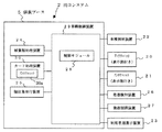
同図に示すように、この実施形態の料金収受システムは、有料道路の入口に設置される入口システム1と、有料道路の出口に設置される出口システム2と、これら入口システム1および出口システム2と通信回線8を介して接続されたホストコンピュータ等の上位装置9とから構成されている。上位装置9は、出口において車線内および車線外で出口処理を行った結果と入口でカード処理した入口情報とを通信回線8から受信し、互いの情報を照合し、差異が確認されたICカードを不正カードとして自身のデータベースに登録し有料道路の入口もしくは出口に配信する機能を有している。この他、不正カードの情報は、有料道路の入口および出口に配信してもよい。入口処理データは、ICカードに記録され、利用者の移動とともに出口にて、ICカードの入口情報に基づき決済処理される。
【0036】
図2は図1の料金収受システムの入口システムの構成を示す図、図3は図2の入口システムにおける機器概略配置図である。
【0037】
これらの図に示すように、入口システム1は、アンテナユニット10、アンテナユニット11、車種判別装置12、通行券自動発行装置13、左ハンドル車用通行券自動発行装置14(以下左ハンドル車用発券装置14と称す)、路側表示装置15、発進検知装置16、発進制御装置17、車線制御装置19とを有している。
【0038】
図4ではアンテナユニット10は、車線内に進入した車両を一旦停車させた運転者が窓から手を伸ばして届く路側部の位置(車両進行方向右側)に配置されている。アンテナユニット10は、上段、中段、下段の3つの高さに第1アンテナ部としての、車線へ向けてせり出し可能なアンテナ部46を備えている。このアンテナ部46の交信距離内に、無線方式のプリペイドICカードである非接触IC式プリペイドカード(以下ICカードと称す)が近付くと、無線通信によりICカードからカード情報が読み出され、カード情報が正常な場合に車両情報、車種情報および入口情報が無線通信(非接触)でICカードに記録される。所定範囲内とはETC車載器の通信範囲とは異なり、例えば数100mm以内の範囲である。なお、近付けられるとは、例えばタッチ(当接)する、あるいはかざす(近接)等の行為が含まれる。
【0039】
ICカードは、カードに内蔵されたICチップに、カードID番号等のカード個別情報(固定情報)と、プリペイド金額(残額)情報および利用履歴情報等の可変情報を、カード情報として記憶している。利用履歴情報には、入口処理の際に特定された車両のナンバープレート番号等の車両情報、判別された車両の車種情報、入口情報等が含まれている。また、カード表面には、このICカードを目視で特定できるようにカード個別のカードID番号が印字されている。
【0040】
アンテナユニット11は、アンテナユニット10と車線を介してほぼ対向する路側部の位置(車両進行方向左側)に配置された、左ハンドル車の運転者用のアンテナユニットである。車種判別装置12は、車線に進入してきた車両を検知すると共に進入車両の軸数・車高・車長・ナンバープレート等の車両情報を取得し、取得した車両情報から車両の車種を判別する。ここでの車種とは、料金収受のために有料道路の運営側で区分した車両の種類であり、例えば大型、大型特殊、中型、小型、軽自動車などである。
【0041】
通行券自動発行装置13は、ICカードに対する入口処理にエラーが発生する等して入口処理が正常に終了しなかった場合に進入車両の車種に応じた通行券を発行する。左ハンドル車用発券装置14は、通行券自動発行装置13と車線を介してほぼ対向する路側部の位置に配置されており、左ハンドルの車両の運転者に対して通行券を発行する。路側表示装置15は、処理状況および誘導内容を表示して車両の運転者に車両の誘導内容を通知する。
【0042】
発進検知装置16は、車両の運転者が通行券を受け取るか、あるいはICカードにて入口処理を行った後、車両が発進を始めて車線から退出するのを検知する。発進制御装置17は、入口処理の結果に応じて車両の通過を許可あるいは阻止するためのものである。車線制御装置19は、上記アンテナユニット10,11を含む各装置と通信線で接続されており、個々の装置から情報を取得し、有料道路の利用に関するさまざまな処理(入口処理等)および路側の各機器の制御(アンテナユニット10,11のカード処理機能を有効/無効にする制御、発進制御装置17の開閉制御等)を行う。
【0043】
なお、上記入口システム1と出口システム2は、対距離課金制のシステムの構成例であるが、均一料金制のシステムでは、有料道路の入口あるいは出口のいずれか一方において料金を徴収するための収受処理を行うため、上記出口システム2と同様に機器構成が入口システム1に導入される。均一料金制のシステムとは有料道路の入口あるいは出口のいずれか一方で均一の料金を一括して徴収する形態のシステムである。
【0044】
図4(a)は入口における通行券自動発行装置13とアンテナユニット10の配置図、図4(b)は入口における左ハンドル車用発券装置14とアンテナユニット11の配置図である。
【0045】
図4(a)に示すように、通行券自動発行装置13には、鉛直方向(異なる高さ)に複数の発券部45が配置されている。この通行券自動発行装置13の複数の発券部45を第1通行券発行部という。各発券部45は、車線制御装置19の制御により、通行券を発行し、その後、完全収納したり再発行する機能を有している。
【0046】
アンテナユニット10は、車線の右側の路側部に立設された棒状の筐体部41を有している。筐体部41には、上段、中段、下段の高さにそれぞれアンテナ部46と表示部47とが配設されている。上段のアンテナ部46および表示部47は、大型車、バス等の座席が比較的高い車両のためのものである。中段のアンテナ部46および表示部47は、ワンボックスカー等の高さの車両のためのものである。下段のアンテナ部46および表示部47は、乗用車、軽自動車、バイク等の比較的座席が低い車両のためのものである。上段、中段、下段の各々のアンテナ部46はICカードとの交信のため車線上にせり出し、交信が終了するともとの位置である筐体部41内に待避するようになっている。各表示部47は、車線制御装置19によって選択されたアンテナ部46のカード処理機能(無線通信機能)が有効なときに点灯、点滅、あるいはメッセージ表示を行う。
【0047】
図4(b)に示すように、左ハンドル車用発券装置14には、通行券自動発行装置13の下段の発券部45と同じ高さの位置に発券部45が配設されている。発券部45は、車線制御装置19の制御により、通行券を発行し、場合によっては発行した通行券を一時退避し、その後、完全収納したり再発行する機能を有している。
【0048】
アンテナユニット11は、車線の左側の路側部に立設された棒状の筐体部41を有している。筐体部41には、アンテナユニット10の下段とほぼ同じ高さの位置にアンテナ部46と表示部47が配設されている。アンテナ部46および表示部47は、左ハンドル車の運転者が窓から手を伸ばして届く位置に配置されている。アンテナ部46はICカードとの交信のため車線上にせり出し、交信が終了するともとの位置である筐体部41内に待避するようになっている。表示部47は、アンテナ部46のカード処理機能(無線通信機能)が有効なときに点灯、点滅、あるいはメッセージ表示を行う。
【0049】
それぞれの発券部45とアンテナ部46との対応関係は、LAN等の通信の場合はアドレス管理テーブルで互いの対応関係を管理する。これ以外に、通信線の系統を分けて物理的な配線で対応関係を管理しても良い。
【0050】
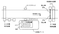
図5は出口システムの構成を示す図、図6は図5の出口システムにおける機器概略配置図である。
【0051】
これらの図に示すように、出口システム2は、アンテナユニット20,21、車種判別装置22、ICカードの処理状況(引去り金額や引去り後の残額等)の表示および処理対象のカードの挿入を促すための表示等を行う利用者用表示装置23、通行券等を処理すると共に係員に対する表示や係員が入力操作を行う紙葉類処理装置24、利用証明書等を発行する領収書発行装置25、発進検知装置26、発進制御装置27、アンテナユニット30a等の無線通信手段を組み込んだカード処理装置30、このカード処理装置30のアンテナユニット30aを介してICカードの情報を取得し料金収受に関する処理を行うと共に各路側機器の制御を行う制御モジュール28を内蔵した車線制御装置29などから構成されている。車種判別装置22は、有料道路を通行し出口の車線(出口レーン)に進入してきた車両(有料道路から退出する車両)を検知すると共にその車両の軸数・車高・車長・ナンバープレート番号等の車両情報を取得し、取得した車両情報から車両の車種を判別する。ここでの車種とは、料金収受のために有料道路の運営側で区分した車両の種類であり、例えば大型、大型特殊、中型、小型、軽自動車などである。入口処理での車種判別情報を用いる場合は、出口での車種判別装置の設置は不要である。
【0052】
カード処理装置30には、ICカードを装置表面にかざす、あるいはタッチすることでICカードから情報を読み取り、処理結果を書き込むアンテナユニット30aが配置されている。車線制御装置29の制御モジュール28はメモリなどCPU機能であり、その内部にはICカードおよび車両に関する処理、係員ブース5内の各機器あるいは路側の各機器の制御を行うための制御プログラムが記憶されている。なお、制御モジュール28そのものをソフトウェアとしてもよい。
【0053】
車線制御装置29は制御モジュール28の処理を実行し有料道路の利用に関するさまざまな処理(出口処理等)および上記各装置の制御を行う。制御モジュール28には、予め出口情報(料金所番号、レーン番号、他の料金所との料金情報等)が記憶されている。制御モジュール28(あるいは紙葉類処理装置24等)は、有料道路から退出する車両のICカードあるいは通行券に記憶(記録)されている入口情報と出口情報とから通行料金(利用料金)を算出し収受する。
【0054】
図7は図6の出口システムのアンテナユニットの構成を示す図、図8(a)はアンテナユニット20の外観図、図8(b)はアンテナユニット21の外観図である。
【0055】
同図に示すように、アンテナユニット20,21は、本体筐体部31a、野外筐体部31bとを通信線で接続した筐体部、制御部33、電源部34、アンテナ部36、表示部37などから構成されており、制御部33を介して車線制御装置29と接続されている。本体筐体部31aには、制御部33、電源部34が収納されている。野外筐体部31bにはアンテナ部36、表示部37が収容されている。制御部33は、この装置全体を統括制御する。また、制御部33は、車線制御装置29の制御モジュール28に接続されており、制御モジュール28と通信することで処理対象のICカードに対するカード処理を行う。電源部34は装置各部に電源を供給する。
【0056】
図8(a)に示すように、アンテナユニット20は、車線の右側の路側部に立設された棒状の野外筐体部31bを有している。野外筐体部31bには、上段、中段、下段にそれぞれアンテナ部36、表示部37が配設されている。上段のアンテナ部36および表示部37は、大型車、バス等の座席が比較的高い車両のためのものである。中段のアンテナ部36および表示部37は、ワンボックスカー等の高さの車両のためのものである。下段のアンテナ部36および表示部37は、乗用車、軽自動車、バイク等の比較的座席が低い車両のためのものである。上段、中段、下段の各々のアンテナ部36はICカードとの交信のため車線上にせり出し、交信が終了すると、もとの位置である野外筐体部31b内に待避するようになっている。各表示部37は、車線制御装置によって選択されたアンテナ部36のカード処理機能(無線通信機能)が有効なときに点灯、点滅、あるいはメッセージ表示を行う。
【0057】
図8(b)に示すように、アンテナユニット21は、車線の左側の路側部に立設された棒状の野外筐体部31bを有している。野外筐体部31bには、アンテナユニット20の下段とほぼ同じ高さの位置にアンテナ部36と表示部37が配設されている。アンテナ部36および表示部37は、左ハンドル車の運転者が窓から手を伸ばして届く位置に配置されている。表示部37は、アンテナ部36のカード処理機能(無線通信機能)が有効なときに点灯、点滅、あるいはメッセージ表示を行う。
【0058】
この料金収受システムで利用されるICカード、つまりカード処理装置30のアンテナユニット30a、アンテナユニット10,11によって処理可能な無線通信方式の非接触プリペイドICカードには、内部の基材に無線タグと呼ばれるICチップと、基材への導体のパターニング(銅箔の印刷配線等)で形成されたアンテナコイル49とが設けられている。
【0059】
次に、入口システム1のアンテナユニット10,11および出口システム2のアンテナユニット20,21におけるアンテナ部43,36のせり出し機構について説明する。このアンテナ部43,36のせり出し機構は、入口システム1のアンテナユニット10,11と出口システム2のアンテナユニット20,21とも共通のため、入口システム1のアンテナユニット10を代表に説明をする。
【0060】
図9は、アンテナユニット10の構造を車線方向から見た側面図である。既に説明したように、アンテナユニット10の筐体部41内には、上段、中段、下段の各高さにそれぞれ車線上へせり出すことの可能なアンテナ保持部としてのアンテナ部46が設けられている。各々のアンテナ部46は各々独立してせり出し/引き込みの動作が制御される。図9の例では、下段のアンテナ部46がせり出た状態にある。このように各々のアンテナ部46は、少なくとも筐体部41内に収容された状態と車線上に突出した状態との2つの状態とをとり得るものとなっている。
【0061】
図10(a)(b)に示すように、アンテナ部46はアンテナコイル49を搭載したアンテナヘッド部48と、このアンテナヘッド部48を先端に着脱自在に支持するアーム部50とを主に構成されている。
【0062】
図11にアンテナヘッド部48の詳細断面を示す。このアンテナヘッド部48はその先端部分あるいは全体がゴムなどの弾性材料を用いて作製されたものである。アンテナヘッド部48の先端には、せり出し時に万が一車両と接触した場合にこれを高感度で感知できるようにセンサ51を埋め込んだ突起部52が設けられている。この突起部52のみがアンテナヘッド部48において弾性材料で作製されたものであっても構わない。上記のセンサ51としては車両60との接触を検出できるものであれば何でもよく、具体的には、圧力センサ、金属センサなどを採用することができる。
【0063】
図17に示すように、センサ51の出力は車線制御装置19に通知される。車線制御装置19はアンテナ部46のせり出し動作途中で突起部52に備えられたセンサ51によって車両60との接触あるいは接近が検知されたなら、直ちにせり出し動作を停止させ、若干の引き込み動作を行って車両60との接触・接近状態の回避を行うようにアンテナユニット10内の制御部33に制御信号を供給する。
【0064】
上記突起部52はアンテナヘッド部48の先端上下端部に設けられており、上下の突起部52の間のアンテナヘッド部48の先端は、車線を向いた垂直面53となっている。さらに、アンテナヘッド部48の先端部分には、上記垂直面53に対してほぼ平行な面内で線状導体を環状に這わせることによって形成された二つのアンテナコイル49,49(空心コイル)が上下に並べて配置されている。この二つのアンテナコイル49,49については後で詳細を説明する。
【0065】
一方、アンテナヘッド部48を先端に支持するアーム部50にはラック等の動力伝達部53が設けられている。この動力伝達部53には駆動ギア54が連結されており、この駆動ギア54の駆動と回転方向を制御することによって、アンテナヘッド部48のせり出し/引き込みの進退動作が行われる。
【0066】
さらに、アンテナヘッド部48はアーム部50の先端に着脱自在に取り付けられている。より具体的には、図12に示すように、アンテナヘッド部48の背面側には水平な溝穴55が設けられており、この溝穴55にアーム部50の先端から水平方向に突出した支持突起56が挿入されている。アンテナヘッド部48の背面側に設けられた溝穴55は車両の進行方向とは逆側を開口(開口55A)させてあり、この開口55Aを通じて支持突起56の挿抜が可能なものとなっている。したがって、アンテナ部46のせり出し時にアンテナヘッド部48が車両60と接触して車両進行方向への押圧を受けた場合、アンテナヘッド部48の溝穴55に従ってアンテナヘッド部48は押圧方向にスライドし、最終的にアーム部50の先端から脱落する。これにより、車両接触時のアンテナヘッド部48、アンテナ部46、アンテナユニット10などの破損防止を図ることができる。
【0067】
次に、アンテナヘッド部48に埋め込まれている二つのアンテナコイル49について詳述する。
【0068】
図13は二つのアンテナコイル49,49によって形成される磁束Bの状態を示している。前述したようにアンテナヘッド部48の先端部には、その先端の垂直面53に対してほぼ平行な面内で線状導体を巻き回すことによって形成された複数のたとえば2つのアンテナコイル49,49(空心コイル)が上下に並べて近接配置されている。各アンテナコイル49,49の巻き方向は互いに逆向きである。各アンテナコイル49に電流Iを図に示す方向にそれぞれ流すと、各アンテナコイル49,49の正面側すなわちアンテナヘッド部48の正面側に垂直な向きの高密な磁束Bが発生し、アンテナヘッド部48は図14に示すようなアンテナ指向性eを持つこととなる。
【0069】
一方、ICカード80には、その主面に対してほぼ平行な向きで線状導体を環状に這わせることによって形成された空心コイル81が埋め込まれている。このICカード80を、アンテナヘッド部48の垂直面53に向け、ICカード80の主面を上下に向けた水平姿勢で接近させて行くと、ICカード80の空心コイル81を通過する垂直な向きの磁束密度が増大し、アンテナヘッド部48のアンテナコイル49,49とICカード80の空心コイル81とが効率的に電磁結合し、大きな相互インダクタンスが確保されることで、電力の伝達効率が向上する。これによって、良好な交信が実現される。しかも、この実施形態では、磁気カードを読み取る一般的なカード読み取り機と同様に、ICカード80をその主面を上下に向けた姿勢でアンテナユニット10に向けて差し出せばよく、ICカード80を差し出す際の車両の運転員の混乱緩和に寄与するものである。
【0070】
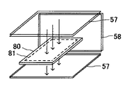
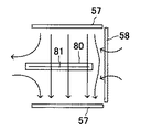
また、図15および図16に示すように、同一巻き方向の2つの第1のアンテナコイル57,57を互いに離間させてほぼ水平の向きに対向して配置するとともに、これらの2つの第1のアンテナコイル57,57の間の空間の1つの側面を覆うようにして第2のアンテナコイル58を垂直な向きで配置する方法もある。このように3つのアンテナコイル57,57,58を組み合わせることによって、2つの対向配置されたアンテナコイル57,57の間に垂直な向きの磁束を高密かつ広範囲に発生させることができる。これにより、2つの対向配置されたアンテナコイル57,57の間に水平な向きでICカード80が配置されることで、アンテナヘッド部48のアンテナコイル57,57とICカード80の空心コイル81との効率的な電磁結合を実現させることができる。
【0071】
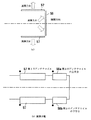
図23(b)は、2つの第1のアンテナコイル57,57と第2のアンテナコイル58の結線図である。2つの第1のアンテナコイル57,57は図23(a)の展開方向に展開した状態にて互いに逆向きに巻かれ、各アンテナコイル57,57,58が立体的に組み合わせた状態では、2つの第1のアンテナコイル57,57の巻き方向は共通となっている。第2のアンテナコイル58は上下に2分割されて巻かれており、これら分割された第2のアンテナコイル58a,58bの各々の巻き方向は逆向きとなっている。これら2分割された第2のアンテナコイル58a,58bが発生する磁束により、2つの第1のアンテナコイル57,57の間に形成される磁束において第2のアンテナコイル58に近接する領域の磁束が打ち消され、2つの対向配置されたアンテナコイル57,57の間に垂直な向きの磁束を広範囲に発生させることができる。
【0072】
次に、アンテナユニット10のアンテナ部46をせり出す動作のタイミングについて説明する。
【0073】
アンテナ部46のせり出し動作を開始させるタイミングとしては、車両60が停止した時点、車両の運転員がICカード80を差し出した時点が理想的と考えられる。
【0074】
まず、車両60の停止を検知する方法について説明する。図17に示すように、車両60をたとえば上から撮像するカメラ61を設け、このカメラ61で撮像した映像の動きを検出し、動きが無くなったとき車線上に移動体が存在しないことを判断する。この移動体が存在しない条件と、車両60が車線上に存在することの条件とが両方成立したことをもって車両停止を検知する。車両60の存在を検知する方法としては、車線を挟んで両側に光センサを構成する発光器62と受光器63とを配置し、これら発光器62と受光器63との光結合の状態により検知する方法や、金属センサ(図示せず)を用いる方法などがある。また、移動体が存在しないことを検知する別の方法としては、路面に圧力センサ64を設置して、検知された圧力に変化がないことをもって移動体が存在しないと判定する方法がある。
【0075】
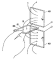
次に、車両の運転員がICカード80を差し出したことを検知する方法を説明する。車両の運転員がICカード80を差し出したことは、アンテナユニット10と車両60との間の映像を捕えるカメラ62をたとえば上方に配置し、車両60から腕が延びてきたことを画像処理にて認識する方法がある。
【0076】
また、アンテナヘッド部48のアンテナコイル49,49の近傍に磁界検知手段を設け、アンテナコイル49,49によって形成される磁界にICカード80のコイルが入り込んで電磁結合している状態を磁界検知手段で検知することで、ICカード80のアンテナヘッド部48への接近を検知する方法がある。磁界検知手段としては、図18に示すように、差動コイル65で空間の磁界を広範囲に検知し、ICカード80の接近による磁界擾乱を検知する方法がある。
【0077】
次に、アンテナユニット10における上段、中段、下段のアンテナ部46の通信制御について説明する。
【0078】
図19に示すように、アンテナ部46の送信機71および受信機72は通信制御部73によって制御される。ここで、ICカード80のコイル81が同時に複数のアンテナ部46のアンテナコイル49と電磁結合すると通信に不具合をもたらすおそれがある。そこで、通信制御部73は、アンテナ部46の送信機71および受信機72を制御して各アンテナ部46のうち一つの通信だけを有効とする。
【0079】
通信を有効にするアンテナ部46を選択する方法として、一定時間各アンテナ部46を動作させて各々の通信電界強度を検知し、もっとも安定した通信電界強度が得られたものを除いて通信を無効とする方法、時分割で各アンテナ部46の通信を処理し、最初に通信リンクが張られたアンテナ部のみを有効とする方法がある。また、はじめに後者の方法にて有効なアンテナ部を決定した後、前者の方法で各アンテナ部46の通信電界強度を監視し、逐次最適なアンテナ部に切り替える方法が考えられる。
【0080】
図20は、アンテナユニット10のアンテナ部46のせり出し機構の他の実施形態を示す側面図である。この例のせり出し機構は、位置エネルギーの開放によりアンテナ部46を軸74を支点に自由回転させ、車線上にアンテナヘッド部48の部分をせり出させるように構成されたものである。車線上に突出させた状態からユニット10内への引き込みは図示しない駆動機構により行われる。
【0081】
次に、図21のフローチャートを参照してこの料金収受システムにおける入口処理の動作の例を説明する。
【0082】
有料道路の入口である料金所において、車両に対して利用に関する処理、例えばICカードに入口情報を書き込む処理等を含む入口処理を行うための車線、つまり入口レーンに車両が進入すると、車種判別装置12によってそれが検知されると共に(S101)、進入車両の軸数・車高・車長・ナンバープレート等の車両情報から車種が判別され(S102)、車線制御装置19に通知される。この通知により、車線制御装置19は、発券対象の機器、つまり通行券自動発行装置24あるいは左ハンドル車用発券装置14に指示する。なお、車線制御装置19は、通知された車種情報より中段、上段からの発券と判定した場合、通行券自動発行装置24のみに指示し、下段からの発券であれば、該当する通行券自動発行装置24あるいは左ハンドル車用発券装置14に指示する。これにより、例えば通行券自動発行装置24等は、当該車両の車種に応じた高さの発券部45の発券口より通行券を発券し、通行券先端が発券部45の発券口から所定の長さだけ突出した位置で通行券が保持される(S103)。
【0083】
車両の運転者である利用者は、通行券ではなく、ICカードを使用する場合、通行券自動発行装置24の中段の発券部45より発券された通行券を抜き取らずに、ICカードを最寄りのアンテナユニット10の自身に一番近い、いずれかのアンテナ部46にICカードの両主面を上下に向けた姿勢でかざす。このとき、車両の停止もしくは車両の運転員がICカードを差し出したことが前述した各検知手段により検知されることで、アンテナ部46が車線側に向かってせり出し、車両の運転者は容易にアンテナ部46の交信距離内にICカードをかざすことができる。
【0084】
アンテナユニット10の各アンテナ部46は、常に電波を発信しており、ICカードがかざされると、ICカードとの無線通信を開始しICカードからカード情報を受信する(S104)。このとき、たとえば最も安定した通信電界強度が得られた一つのアンテナ部46の通信のみを有効にする方式、あるいは、時分割で各アンテナ部46の通信を処理し、最初に通信リンクが張られたアンテナ部46のみを有効とする方式を採用することで、ICカードのコイルと一つのアンテナ部のアンテナコイルとだけを電磁結合させ、より安定した通信が可能になる。
【0085】
カード情報が受信されると、アンテナ部46によりカード処理(アンテナ処理)を開始する旨がアンテナユニット10から車線制御装置19に通知される。カード処理(アンテナ処理)とは、ICカードから得られたカード情報が正常か否かの確認、カード情報が正常な場合にICカードへの車両情報、車種情報、入口情報の記録、および残額情報の読み取り確認等の処理である。カード情報が正常な場合のカード処理としては、アンテナ部46から車両情報(ナンバープレート番号)、車種情報(普通車を示す番号情報)および入口情報(料金所番号、レーン番号、入口通過時刻等)がICカードに送信されて記録される。
【0086】
車線制御装置19は、アンテナ処理を行う旨を通行券自動発行装置24に指示し、通行券自動発行装置24は、発券・保持中の通行券を発券部45の発券口内に取り込み、一時保留(退避)する。この間にもアンテナ部46によりカード処理が行われる(S105)。
【0087】
カード処理が予め設定された時間内に正常終了しなかった場合(S106のNG)、車線制御装置19は、路側表示装置15と通行券自動発行装置24に指示し、路側表示装置15は、カード処理が正常に終了しなかったため、通行券を受け取る必要がある旨を表示する(S107)。また、通行券自動発行装置24は、一時保留(退避)していた通行券を当該車両に対して発行する(S108)。
【0088】
通行券自動発行装置13が、内部のセンサで通行券の抜き取りを検知すると(S109)、車線制御装置19は、ICカードに対する処理を禁止し(S110)、ICカードの処理を受け付ないようにする。
【0089】
一方、カード処理が予め設定された時間内に正常終了した場合(S106のOK)、続いて、車線制御装置19は、残額の確認処理を行う(S111)。残額確認処理は、ICカードから取得した実際の残額と車種・料金所毎に予め設定された最低残額とを比較することで行われる。
【0090】
残額の確認処理を行った結果、残額が正常であった場合(S111のOK)、車線制御装置19は、路側表示装置15にカード処理が正常に終了した旨、および、残額を表示する(S112)。そして、万一、残額が車種・料金所毎に、予め設定された金額に満たない場合は、残額不足である旨を合わせて表示する(S113)。
【0091】
車線制御装置19は、自身のメモリにICカードの個別情報を記録すると共に、通行券自動発行装置13に不要通行券の収納を指示し、当該車両に対する一時保留中の通行券を不要通行券として完全に収納させる(S114)。
【0092】
さらに、車線制御装置19は、通行券自動発行装置13および左ハンドル車用発券装置14に、通行券発行を禁止する指示とICカードの再処理を禁止する指示を出し(S115)、当該車両に対する一時保留中の通行券を不要通行券として完全に収納する。
【0093】
そして、発進検知装置16で当該車両の発進検知および車種判別装置12により後続車両の進入が検知されると(S116)、車線制御装置19は、自身の処理を初期の待機状態に戻し(S116)、ICカードの処理の受け付けを再開する(S117)。
【0094】
次に、図22のフローチャートを参照して出口における料金収受処理の動作例を説明する。
【0095】
有料道路の出口である料金所において、車両に対して利用に関する処理、例えばICカードから入口情報を含むカード情報を読み出して有料道路の通行料金の収受処理を行うための車線、つまり出口レーンでは、各アンテナユニット20,21の処理状態(待機状態、カード処理待ち状態、処理中および処理結果等)が常に車線制御装置29へ通知され、その制御モジュール28から紙葉類処理装置24に通知されている(S201)。
【0096】
このような中で、有料道路から退出する車両が出口レーンに進入すると、車両の進入が車種判別装置22により検知および車種判別され(S202)、車線制御装置29は、出口処理を開始する。
【0097】
車種判別装置22により車両が検知されると、車線制御装置29は、まず、カード処理を行うためのアンテナユニット20あるいはアンテナユニット21を動作させカード処理機能を有効にする。
【0098】
車線内に進入した車両をアンテナユニット20,21の位置で停止させた車両の運転者が、窓から手を出して少なくとも一枚のICカードを最寄のアンテナ部36に当該ICカードの両主面を上下に向けた姿勢でかざす。このとき、車両の停止もしくは車両の運転員がICカードを差し出したことが前述した各検知手段により検知されることで、アンテナ部36が車線側に向かってせり出し、車両の運転者は容易にアンテナ部36の交信距離内にICカードをかざすことができる。
【0099】
アンテナユニット20の各アンテナ部36は、常に電波を発信しており、ICカードがかざされると、ICカードとの無線通信を開始し一枚目のICカードから順にカード情報を受信する(S202)。このとき、たとえば最も安定した通信電界強度が得られた一つのアンテナ部36の通信のみを有効にする方式、あるいは、時分割で各アンテナ部36の通信を処理し、最初に通信リンクが張られたアンテナ部36のみを有効とする方式を採用することで、ICカードのコイルと一つのアンテナ部36のアンテナコイルとだけを電磁結合させ、より安定した通信が可能になる。
【0100】
アンテナユニット20は、そのICカードのカード個別情報等の固定情報および車種情報を含む入口情報やプリペイド残額情報等の可変情報を読み取り(S203)、読み取ったICカード個別情報の数から、処理すべきICカードの枚数を確認する(S204)。つまり何枚のICカードを処理しなければならないかを確認する。処理すべきカードの枚数を確認した後、アンテナユニット20は、ICカード全枚数分のICカード固定情報、可変情報等を順に読み取ると(S205)、この確認結果(読取情報)を車線制御装置29の制御モジュール28を通じて紙葉類処理装置24に送信する(S206)。
【0101】
この際、制御モジュール28は、アンテナユニット20からICカード全枚数分のICカード固定情報、可変情報、(車種情報・入口情報)等の読取結果(読取情報)が受信されると、その読取結果(読取情報)と自身に設定されている料金表とから算出した収受すべき料金と、処理中のアンテナユニット(アンテナユニット20,21か)を識別するための情報(アンテナユニット識別情報)とを合わせて、紙葉類処理装置24に送信する(S206)。
【0102】
紙葉類処理装置24は、ICカードの読取結果(読取情報)が受信されると、その読取結果(読取情報)と収受すべき料金とアンテナユニット識別情報とを表示部に表示する(S207)。
【0103】
また、制御モジュール28は、ICカード内に記録された車両情報と、出口車種判別処理の結果とを突き合せ(S208)、整合性の確認を行う。なお、読取結果、複数のICカードに入口情報が記録されていた場合や、車両情報の突き合せの結果、不整合が確認された場合は、異なる車両間でICカードの交換等といった不正行為が行われた可能性があるため異常処理する(S209)。異常処理としては、不整合のICカード個別情報を表示部に表示あるいは音声メッセージで係員に報知する処理である。
【0104】
紙葉類処理装置24に読取結果・収受すべき料金の表示が完了すると、係員が、該当するアンテナユニットで処理中の車両の車種と表示内容を確認する(S210)。その後、係員が紙葉類処理装置24の表示部で表示内容を確認し、料金の確定入力を行い(S211)、料金が確定すると、制御モジュール28は、該当アンテナユニット20に、料金引去り後の情報および料金収受処理の履歴情報の記録を指示し、この指示に従ってアンテナユニット20は、入口情報が記録されていたICカードから料金の引去り処理を開始する。ここで、1枚目のICカードの全残額を引き去っても徴収額が不足する場合は、2枚目以降の残額が少ないカードから、順次、料金徴収が完了するまで料金の引き去り処理を行う。
【0105】
料金引き去り処理では、入口情報を含むカード情報を記憶していたICカードに必要な情報(残額からの引き去った後の残額情報および料金収受処理の履歴情報)の記録を行う(S212)。なお、一連の料金収受処理を行っている間は、アンテナユニット20の表示部37には処理中の旨が表示される。
【0106】
例えば初めのICカードに対する引去り処理で残高不足が発生した場合(S213)、2枚目のICカードがある場合、制御モジュール28は、アンテナユニット20に対して残額の少ない順に引き去り処理を実行させる(S214)。また、残高不足が無く(S215)、料金収受が正常に終了した場合(S216)、正常終了した旨および利用料金や残額等がアンテナ部36の近傍の表示部37あるいは利用者用表示装置23に表示される(S217)。
【0107】
正常終了後、車線制御装置29は、発進制御装置27の阻止棒27a,27bを開放して、当該車両の通行を許可し、これにより、車両が発進して、発進検知装置26により車両の通過が検知された時点で、発進制御装置27の阻止棒27a,27bを閉じる(S218)。
【0108】
上記ステップS204、ステップS205、ステップS212、ステップS214のいずれかの処理でエラーが発生した場合は(S219)、エラーの旨が該当表示部に表示され(S220)、エラー処理が行われる(S221)。
【0109】
また、車種判別装置22により後続車両の進入が検知されると、車線制御装置29は、後続車両に対するICカードの処理の受け付けを開始する。
【0110】
以上、入口と出口での処理において、アンテナユニット(たとえばアンテナユニット10)のアンテナ部(たとえばアンテナ部46)のせり出し動作時において、アンテナヘッド部48の先端の突起部52が車両に接触あるいは接近した場合には、このことがアンテナヘッド部48の突起部52に取り付けられているセンサ51により検知され、アンテナユニット10内の制御部70に通知される。制御部70は、この通知を受けたなら、直ちにせり出し動作を停止させ、若干の引き込み動作を行って車両60との接触・接近状態の回避処理を行う。
【0111】
以上本発明の実施形態を説明したが、本発明は、上述の実施形態にのみ限定されるものではなく、本発明の要旨を逸脱しない範囲内において種々変更を加え得ることは勿論である。
【0112】
【発明の効果】
以上説明したように、請求項1記載の発明によれば、車両の運転員とアンテナコイルとの距離が縮まり、ユーザが無理なくICカードをアンテナの交信距離内にかざすことができる。請求項2および請求項3に記載の発明によれば、アンテナ保持部を車線上に突出させた場合に考えられるアンテナ保持部と車両との接触による損害のレベルを低減できる。請求項4記載の発明によれば、アンテナヘッド部への車両接触時の破損防止を図ることができる。請求項5および請求項6に記載の発明によれば、アンテナコイルとICカード内のコイルとの効率的な電磁結合が可能となり安定した交信が可能になる。請求項8ないし請求項10に記載の発明によれば、ICカード内のコイルが同時に複数のアンテナ保持部のアンテナコイルと電磁結合することに起因する通信の不具合を解消することができる。請求項11ないし請求項15に記載の発明によれば、アンテナ保持部を安全なタイミングで車線上に突出させることができる。
【図面の簡単な説明】
【図1】本発明に係る一つの実施の形態の料金収受システムの構成を示す図。
【図2】図1の料金収受システムの入口システムの構成を示す図。
【図3】図2の入口システムの機器配置図。
【図4】(a)は入口における通行券自動発行装置13とアンテナユニット10の配置図、(b)は入口における左ハンドル車用発券装置14とアンテナユニット11の配置図。
【図5】図1の料金収受システムの出口システムの構成を示す図。
【図6】図4の出口システムの機器配置図。
【図7】出口におけるアンテナユニット20,21の構成を示す図。
【図8】(a)はアンテナユニット20の外観図、(b)はアンテナユニット21の外観図。
【図9】アンテナユニット10におけるアンテナせり出し機構を車線方向から見た側面図。
【図10】(a)は図9のアンテナ部46の構成を示す側面図、(b)はアンテナ部46のアンテナヘッド部48とアーム部50とを分解した様子を示す側面図。
【図11】図10のアンテナヘッド部48の詳細断面図。
【図12】アンテナヘッド部48の横から押圧による脱落の動きを説明する側面図。
【図13】アンテナヘッド部48のアンテナの構造を示す斜視図。
【図14】図13のアンテナの指向性を示す図。
【図15】アンテナヘッド部48の他のアンテナの構造を示す斜視図。
【図16】図15のアンテナにより発生する磁束の方向を示す側面図。
【図17】車両60の停止を検知する方法を説明するための図。
【図18】作動コイル65を用いてICカード80のアンテナヘッド部48への接近を検知する方法を示す図。
【図19】各アンテナ部の通信制御方式を説明するブロック図。
【図20】アンテナユニット10における別のアンテナせり出し機構を車線方向から見た側面図。
【図21】入口処理の流れを示すフローチャート。
【図22】出口処理の流れを示すフローチャート。
【図23】図16の2つの第1のアンテナコイル57,57と第2のアンテナコイル58の結線図である。
【符号の説明】
10,11…アンテナユニット、19…車線制御装置、20,21…アンテナユニット、29…車線制御装置、30…カード処理装置、31…筐体部、33…制御部、36…アンテナ部、46…アンテナ部、47…表示部、48…アンテナヘッド部、49…アンテナコイル、50…アーム部、51…センサ、52…突起部、53…垂直面、53…動力伝達部、54…駆動ギア、55…溝穴、55A…開口、56…支持突起、57…第1のアンテナコイル、58…第2のアンテナコイル、60…車両、70…制御部、71…送信機、72…受信機、73…通信制御部、80…ICカード、81…コイル。[0001]
TECHNICAL FIELD OF THE INVENTION
The present invention relates to a card processing system for paying a toll on a toll road with a prepaid IC card, for example, and an antenna unit used for the card processing system.
[0002]
[Prior art]
At present, magnetic prepaid cards (hereinafter, referred to as magnetic cards) widely available in the market can be said to be highly convenient for users because they can be used by an unspecified number of people in anonymous and indefinite periods. On the other hand, magnetic cards always carry the risk of unauthorized rewriting of data such as money information, and in terms of security vulnerabilities, only the remaining balance is withdrawn. Is commonly done.
[0003]
Therefore, in recent years, security has been strengthened by converting a highly convenient magnetic card into an IC card as described above. For example, in a transportation system such as a railway, a card processing system using a wireless prepaid IC card that can enter and exit by simply touching or holding an automatic ticket gate installed at a ticket gate of a station (for example, see Patent Document 1). It has already been realized.
[0004]
[Patent Document 1]
Japanese Patent No. 3256642 (
[0005]
[Problems to be solved by the invention]
The introduction of this wireless prepaid IC card (hereinafter referred to as IC card) for toll collection on toll roads is being studied. In the application of the IC card to toll collection on a toll road, an operation is assumed in which a person puts the IC card within a communicable distance with an antenna while riding in a vehicle.
[0006]
In general, in an automatic ticket gate, when a surface of an IC card faces an antenna surface, a magnetic flux in a direction perpendicular to those surfaces is generated so as to pass through each coil of both the antenna and the card. Power transmission and wireless communication are realized using the induced voltage due to the induced magnetic flux of the coil. The communication distance of the electromagnetic induction type IC card is 100 mm or less.
[0007]
However, when the vehicle is stopped at a position distant from the antenna, it is expected that an IC card inserted through a window of the vehicle may not be able to reach the communication distance with the antenna. In addition, in introducing an IC card to a toll road, there is a construction limit (for example, 250 mm as an example of a highway) as a contact clearance between a vehicle and a building, so that it is necessary to narrow the vehicle toward roadside equipment. Even if it is taken into consideration, it is possible for a non-vehicle driver to force the IC card within the communication distance with the antenna, but may impose a heavy burden.
[0008]
The present invention has been made to solve such a problem, and an object of the present invention is to provide an antenna unit and a card processing system in which a user can easily hold an IC card within a communication distance of an antenna of a roadside device. I do.
[0009]
Another object of the present invention is to provide an antenna unit and a card processing system capable of improving the reliability of communication between an IC card and an antenna.
[0010]
[Means for Solving the Problems]
In order to solve the above-described problem, an antenna unit according to the first aspect of the present invention is an antenna unit installed on a road side portion of a lane in which a process related to use of a toll road is performed on a vehicle passing through the toll road. There is an antenna holding portion holding an antenna coil for performing wireless communication through an electromagnetic coupling with an IC card at a front end portion, and a position between a position where the antenna holding portion is projected on the lane and a position where the antenna holding portion is accommodated in the unit. And a drive mechanism for moving back and forth.
[0011]
By projecting the antenna holding part holding the antenna coil at the tip into the lane and bringing the antenna coil closer to the vehicle on the lane, the distance between the driver of the vehicle and the antenna coil is reduced, and the user can easily use the IC card. Can be held over the communication distance of the antenna.
[0012]
An antenna unit according to a second aspect of the present invention is the antenna unit according to the first aspect, wherein the distal end of the antenna holding portion is made of an elastic material. This can reduce the level of damage caused by contact between the antenna holding unit and the vehicle, which can be caused when the antenna holding unit protrudes above the lane.
[0013]
An antenna unit according to a third aspect of the present invention is the antenna unit according to the first aspect, wherein the detection unit detects contact or proximity of the tip of the antenna holding unit to the vehicle, and the driving mechanism drives the antenna holding unit in the unit. And a control unit that controls a drive mechanism to stop the movement of the antenna holding unit when contact or proximity to the vehicle is detected by the detection unit while moving from the accommodation position to the protruding position on the lane. It is further characterized by comprising:
[0014]
If the contact or proximity of the tip of the antenna holding part to the vehicle is detected while moving the antenna holding part from the storage position in the unit to the projecting position on the lane, the movement of the antenna holding part is stopped immediately. Thus, it is possible to reduce the level of damage caused by contact between the antenna holding unit and the vehicle, which is considered when the antenna holding unit protrudes above the lane.
[0015]
An antenna unit according to a fourth aspect of the present invention is the antenna unit according to the first aspect, wherein the antenna holding unit further includes an antenna head unit on which an antenna coil is mounted, and a support unit that supports the antenna head unit at a distal end. The antenna head is mounted so that the antenna head can be separated from the support by pressing in the vehicle traveling direction on the lane.
[0016]
If the tip of the antenna is in contact with the vehicle and is pressed in the direction of travel when the antenna holder is projected on the lane, the antenna head will fall off the tip of the support, The impact applied to the holding portion is reduced, and breakage can be prevented.
[0017]
An antenna unit according to a fifth aspect of the present invention is the antenna unit according to the first aspect, wherein two antenna coils wound respectively along a substantially vertical surface are vertically arranged at the tip of the antenna holding portion. It is characterized by being arranged close to.
[0018]
When a current is applied to each antenna coil, a dense magnetic flux is generated in the direction perpendicular to the front side of each antenna coil. When the IC card is approached to each antenna coil with its main surface facing up and down, the density of the magnetic flux in the vertical direction passing through the coil in the IC card increases, and the antenna coil and the coil in the IC card are increased. Are efficiently electromagnetically coupled, and a large mutual inductance is ensured, so that power transmission efficiency is improved and good communication is realized.
[0019]
Note that the two antenna coils are not necessarily wound respectively along substantially vertical planes, and are not necessarily arranged close to one another vertically. What is necessary is just to wind two antenna coils along substantially the same plane, and to arrange them close to each other along the substantially same plane.
[0020]
An antenna unit according to a sixth aspect of the present invention is the antenna unit according to the first aspect, wherein two first antenna coils respectively wound around a substantially horizontal surface are provided at the tip of the antenna holding portion. A second antenna coil, which is arranged facing away from the first antenna coil and wound along a substantially vertical surface so as to substantially cover one side surface of a space between these two first antenna coils, is arranged. It is characterized by having been done.
[0021]
By combining the three antenna coils in this manner, it is possible to generate a magnetic flux in a vertical direction between the two antenna coils arranged opposite to each other with high density and a wide range. Therefore, if the IC card is arranged in a horizontal direction between these two opposed antenna coils, efficient electromagnetic coupling between the antenna coil and the coil in the IC card is realized, and good communication is realized. You. The present invention is not limited to this, and two first antenna coils are wound along the first surface, are arranged to be separated from each other and face each other, and the second antenna coil is substantially orthogonal to the first surface. The second antenna coil may be wound along the surface and arranged so as to substantially cover one second surface of the space between the two first antenna coils.
[0022]
An antenna unit according to a seventh aspect of the present invention is the antenna unit according to the first aspect, further comprising a plurality of antenna holding portions, each of which is independently moved between a position protruding on a lane and a position in the unit. It is characterized by being moved.
[0023]
An antenna unit according to an eighth aspect of the present invention is the antenna unit according to the seventh aspect, further comprising: a plurality of transmitters and receivers that individually transmit and receive signals using the antenna coils of the individual antenna holding units; It is characterized by comprising a communication control unit that measures each electric field strength or reception strength based on a reception signal from the receiver and selects a set of transmitters and receivers to function effectively.
[0024]
An antenna unit according to a ninth aspect of the present invention is the antenna unit according to the seventh aspect, further comprising a plurality of transmitters and receivers that individually transmit and receive signals using the antenna coils of the individual antenna holding units, A communication control unit for processing the communication using the respective sets of transmitters and receivers in a time-division manner and enabling a set of transmitters and receivers to which a communication link is initially established. And
[0025]
An antenna unit according to a tenth aspect of the present invention is the antenna unit according to the seventh aspect, wherein a plurality of transmitters and receivers each individually transmit and receive a signal using an antenna coil of each of the antenna holding units, The communication using the respective sets of transmitters and receivers is processed in a time-division manner, and first, a set of transmitters and receivers provided with a communication link are enabled, and based on the reception signals from the respective receivers. And a communication control unit that measures each electric field strength or reception strength and sequentially switches to an optimal set of a transmitter and a receiver.
[0026]
According to the eighth, ninth, and tenth aspects of the present invention, it is possible to eliminate a communication problem caused by a coil in an IC card being electromagnetically coupled to antenna coils of a plurality of antenna holding units at the same time. Can be.
[0027]
An eleventh aspect of the present invention provides a card processing system including the antenna unit according to any one of the first to tenth aspects.
[0028]
A card processing system according to a twelfth aspect of the present invention is the card processing system according to the eleventh aspect, wherein the vehicle stop detecting means for detecting the stop of the vehicle on the lane and the vehicle on the lane by the vehicle stop detecting means. And a control unit that controls a driving mechanism of the antenna unit so that the antenna holding unit protrudes above the lane when the stop of the vehicle is detected.
[0029]
A card processing system according to a thirteenth aspect of the present invention is the card processing system according to the twelfth aspect, wherein the vehicle stop detecting means determines whether or not the vehicle is present on the lane by an imaging means for imaging the lane. Detecting means for detecting, when the movement of the image captured by the image capturing means is not detected and the presence of the vehicle on the lane is detected by the detecting means, A stop for controlling a driving mechanism of the antenna unit so that the portion protrudes above the lane is detected.
[0030]
A card processing system according to a fourteenth aspect of the present invention is the card processing system according to the eleventh aspect, wherein the card approach detection means detects the approach of the IC card to the tip of the antenna holding part, and the card approach detection means A control unit that controls a driving mechanism of the antenna unit so that the antenna holding unit projects on the lane when the approach of the IC card to the tip of the antenna holding unit is detected by the control unit. It is characterized by.
[0031]
A card processing system according to a fifteenth aspect of the present invention is the card processing system according to the fourteenth aspect, wherein the card approach detection unit captures an image between the antenna unit and a vehicle on the lane, And a recognition unit for recognizing that the arm has extended from the vehicle based on the image captured by the imaging unit as the approach of the IC card to the tip of the antenna holding unit. I do.
[0032]
According to the card processing system of the present invention, the antenna holding portion can be projected onto the lane at a safe timing.
[0033]
BEST MODE FOR CARRYING OUT THE INVENTION
Hereinafter, embodiments of the present invention will be described in detail with reference to the drawings.
[0034]
FIG. 1 is a diagram showing a toll road toll collection system which is one embodiment of a card processing system according to the present invention.
[0035]
As shown in the figure, the toll collection system of this embodiment includes an
[0036]
FIG. 2 is a diagram showing a configuration of an entrance system of the toll collection system of FIG. 1, and FIG. 3 is a schematic layout diagram of devices in the entrance system of FIG.
[0037]
As shown in these drawings, the
[0038]
In FIG. 4, the
[0039]
The IC card stores, as card information, card individual information (fixed information) such as a card ID number and variable information such as prepaid amount (remaining amount) information and usage history information in an IC chip built in the card. . The usage history information includes vehicle information such as a license plate number of the vehicle specified at the time of the entrance processing, vehicle type information of the determined vehicle, entrance information, and the like. The card ID number of each card is printed on the surface of the card so that the IC card can be visually identified.
[0040]
The antenna unit 11 is an antenna unit for a driver of a left-hand drive vehicle, which is disposed at a roadside position (left side in the vehicle traveling direction) substantially facing the
[0041]
The automatic toll ticket issuing device 13 issues a toll ticket according to the type of the approaching vehicle when the entrance process is not completed normally due to an error in the entrance process for the IC card or the like. The
[0042]
The start detecting
[0043]
The
[0044]
FIG. 4A is a layout diagram of the automatic ticket issuing device 13 and the
[0045]
As shown in FIG. 4A, a plurality of ticket issuing units 45 are arranged in the automatic toll ticket issuing device 13 in a vertical direction (different heights). The plurality of ticket issuing units 45 of the automatic toll ticket issuing device 13 are referred to as a first toll ticket issuing unit. Each ticket issuing unit 45 has a function of issuing a toll ticket under the control of the
[0046]
The
[0047]
As shown in FIG. 4B, the ticket issuing device 45 for the left-hand drive vehicle is provided with a ticket issuing unit 45 at the same height as the ticket issuing unit 45 at the lower stage of the automatic ticket issuing device 13. The ticket issuing unit 45 has a function of issuing a toll ticket under the control of the
[0048]
The antenna unit 11 has a rod-shaped
[0049]
The correspondence between each ticket issuing unit 45 and the
[0050]
FIG. 5 is a diagram showing a configuration of the exit system, and FIG. 6 is a schematic layout diagram of devices in the exit system of FIG.
[0051]
As shown in these figures, the
[0052]
The
[0053]
The lane control device 29 executes the processing of the
[0054]
7 is a diagram showing the configuration of the antenna unit of the exit system in FIG. 6, FIG. 8A is an external view of the
[0055]
As shown in the figure, the
[0056]
As shown in FIG. 8A, the
[0057]
As shown in FIG. 8 (b), the
[0058]
An IC card used in this toll collection system, that is, a wireless communication non-contact prepaid IC card that can be processed by the
[0059]
Next, the protrusion mechanism of the antenna units 43 and 36 in the
[0060]
FIG. 9 is a side view of the structure of the
[0061]
As shown in FIGS. 10A and 10B, the
[0062]
FIG. 11 shows a detailed cross section of the
[0063]
As shown in FIG. 17, the output of the
[0064]
The
[0065]
On the other hand, a
[0066]
Further, the
[0067]
Next, the two
[0068]
FIG. 13 shows the state of the magnetic flux B formed by the two antenna coils 49. As described above, the tip of the
[0069]
On the other hand, an air-
[0070]
As shown in FIGS. 15 and 16, two first antenna coils 57, 57 having the same winding direction are spaced apart from each other and arranged to face each other in a substantially horizontal direction. There is also a method of arranging the
[0071]
FIG. 23B is a connection diagram of two first antenna coils 57, 57 and a
[0072]
Next, the timing of the operation of protruding the
[0073]
It is considered that the timing at which the projecting operation of the
[0074]
First, a method for detecting the stop of the
[0075]
Next, a method for detecting that the driver of the vehicle has inserted the
[0076]
Further, a magnetic field detecting means is provided near the antenna coils 49, 49 of the
[0077]
Next, communication control of the upper, middle, and
[0078]
As shown in FIG. 19, the
[0079]
As a method of selecting the
[0080]
FIG. 20 is a side view showing another embodiment of the protruding mechanism of the
[0081]
Next, an example of the operation of the entrance process in this toll collection system will be described with reference to the flowchart of FIG.
[0082]
At a tollgate which is an entrance of a toll road, when a vehicle enters a lane for performing an entrance process including a process of writing entrance information into an IC card, that is, a process for writing entrance information to an IC card, that is, an entrance lane, a vehicle type discriminating apparatus is provided. 12, the vehicle type is detected (S101), the vehicle type is determined from vehicle information such as the number of axles, the vehicle height, the vehicle length, and the license plate of the approaching vehicle (S102), and the
[0083]
When a user who is a driver of the vehicle uses an IC card instead of a toll ticket, the user can remove the toll ticket issued from the middle ticket issuing unit 45 at the middle stage of the automatic toll ticket issuing device 24 and place the IC card at the nearest location. The IC card is held over one of the
[0084]
Each
[0085]
When the card information is received, the
[0086]
The
[0087]
If the card processing does not end normally within a preset time (NG in S106), the
[0088]
When the automatic toll ticket issuing device 13 detects the withdrawal of the toll ticket by the internal sensor (S109), the
[0089]
On the other hand, when the card processing has been normally completed within the preset time (OK in S106), subsequently, the
[0090]
As a result of the remaining amount confirmation processing, if the remaining amount is normal (OK in S111), the
[0091]
The
[0092]
Further, the
[0093]
Then, when the
[0094]
Next, an operation example of the toll collection process at the exit will be described with reference to the flowchart in FIG.
[0095]
At a tollgate which is an exit of a toll road, in a lane, ie, an exit lane, for processing related to the use of a vehicle, for example, reading card information including entrance information from an IC card and performing toll collection processing of a toll road, The processing state (standby state, card processing waiting state, processing, processing result, etc.) of each of the
[0096]
In such a situation, when the vehicle exiting from the toll road enters the exit lane, the entry of the vehicle is detected and identified by the vehicle type identification device 22 (S202), and the lane control device 29 starts the exit process.
[0097]
When a vehicle is detected by the vehicle type discrimination device 22, the lane control device 29 first activates the
[0098]
The driver of the vehicle, which has stopped the vehicle that has entered the lane at the position of the
[0099]
Each antenna unit 36 of the
[0100]
The
[0101]
At this time, when the
[0102]
When the reading result (reading information) of the IC card is received, the paper sheet processing device 24 displays the reading result (reading information), the fee to be received, and the antenna unit identification information on the display unit (S207). .
[0103]
Further, the
[0104]
When the display of the reading result and the fee to be received is completed on the sheet processing device 24, the attendant checks the type of the vehicle being processed by the corresponding antenna unit and the display content (S210). Thereafter, the attendant checks the display contents on the display unit of the paper sheet processing device 24, and inputs a fee confirmation (S211). When the fee is confirmed, the
[0105]
In the fee withdrawal process, information necessary for the IC card that has stored the card information including the entrance information (the balance information after withdrawal from the balance and the history information of the fee collection process) is recorded (S212). During the series of fee collection processing, the
[0106]
For example, if a balance shortage occurs in the first IC card withdrawal process (S213), and if there is a second IC card, the
[0107]
After the normal end, the lane control device 29 opens the blocking bars 27a and 27b of the start control device 27 to permit the vehicle to pass, whereby the vehicle starts and the start detection device 26 passes the vehicle. Is detected, the blocking bars 27a and 27b of the start control device 27 are closed (S218).
[0108]
If an error occurs in any of the above-described steps S204, S205, S212, and S214 (S219), an error message is displayed on the corresponding display unit (S220), and error processing is performed (S221). .
[0109]
Further, when the vehicle type discriminating device 22 detects the entry of the following vehicle, the lane control device 29 starts accepting the processing of the IC card for the following vehicle.
[0110]
As described above, in the processing at the entrance and the exit, the
[0111]
Although the embodiments of the present invention have been described above, the present invention is not limited to the above-described embodiments, and it goes without saying that various changes can be made without departing from the spirit of the present invention.
[0112]
【The invention's effect】
As described above, according to the first aspect of the invention, the distance between the driver of the vehicle and the antenna coil is reduced, and the user can easily hold the IC card within the communication distance of the antenna. According to the second and third aspects of the present invention, it is possible to reduce the level of damage caused by contact between the antenna holding portion and the vehicle, which is considered when the antenna holding portion is projected on the lane. According to the fourth aspect of the invention, it is possible to prevent breakage when the vehicle comes into contact with the antenna head. According to the fifth and sixth aspects of the present invention, efficient electromagnetic coupling between the antenna coil and the coil in the IC card becomes possible, and stable communication becomes possible. According to the invention described in
[Brief description of the drawings]
FIG. 1 is a diagram showing a configuration of a toll collection system according to an embodiment of the present invention.
FIG. 2 is a diagram showing a configuration of an entrance system of the toll collection system of FIG. 1;
FIG. 3 is a device layout of the entrance system of FIG. 2;
4A is a layout diagram of the automatic ticket issuing device 13 and the
FIG. 5 is a diagram showing a configuration of an exit system of the toll collection system of FIG. 1;
FIG. 6 is a device layout diagram of the exit system of FIG. 4;
FIG. 7 is a diagram showing a configuration of
8A is an external view of an
FIG. 9 is a side view of the antenna protruding mechanism in the antenna unit viewed from the lane direction.
10A is a side view showing the configuration of the
11 is a detailed cross-sectional view of the
FIG. 12 is a side view illustrating the movement of the
FIG. 13 is a perspective view showing the structure of the antenna of the
FIG. 14 is a diagram showing the directivity of the antenna of FIG. 13;
15 is a perspective view showing another antenna structure of the
FIG. 16 is a side view showing the direction of the magnetic flux generated by the antenna of FIG.
FIG. 17 is a diagram for explaining a method of detecting a stop of the
FIG. 18 is a diagram showing a method of detecting approach of the
FIG. 19 is a block diagram illustrating a communication control method of each antenna unit.
FIG. 20 is a side view of another antenna protruding mechanism in the antenna unit viewed from a lane direction.
FIG. 21 is a flowchart showing the flow of an entrance process.
FIG. 22 is a flowchart showing the flow of an exit process.
23 is a connection diagram of the two first antenna coils 57 and 57 and the
[Explanation of symbols]
10, 11: Antenna unit, 19: Lane control device, 20, 21: Antenna unit, 29: Lane control device, 30: Card processing device, 31: Housing unit, 33: Control unit, 36: Antenna unit, 46: Antenna part, 47 ... Display part, 48 ... Antenna head part, 49 ... Antenna coil, 50 ... Arm part, 51 ... Sensor, 52 ... Protrusion part, 53 ... Vertical surface, 53 ... Power transmission part, 54 ... Drive gear, 55 ... Slot, 55A ... Opening, 56 ... Support projection, 57 ... First antenna coil, 58 ... Second antenna coil, 60 ... Vehicle, 70 ... Control unit, 71 ... Transmitter, 72 ... Receiver, 73 ... Communication control unit, 80: IC card, 81: coil.
Claims (21)
ICカードと電磁結合を通じて無線通信を行うアンテナコイルを先端部に保持したアンテナ保持部と、
このアンテナ保持部を前記車線上に突出させた位置とユニット内に収容した位置との間で進退自在に移動させる駆動機構と
を具備することを特徴とするアンテナユニット。An antenna unit installed on a road side portion of a lane in which a process related to use of the toll road is performed on a vehicle passing through the toll road,
An antenna holding unit that holds an antenna coil that performs wireless communication through electromagnetic coupling with an IC card at a tip thereof;
An antenna unit, comprising: a driving mechanism for moving the antenna holding portion forward and backward between a position where the antenna holding portion protrudes on the lane and a position where the antenna holding portion is accommodated in the unit.
前記駆動機構によって前記アンテナ保持部を前記ユニット内の収容位置から前記車線上の突出位置へ向けて移動させる間に前記検知手段により前記車両との接触もしくは近接を検知されたとき、前記アンテナ保持部の移動を停止させるように前記駆動機構を制御する制御部と
をさらに具備することを特徴とする請求項1に記載のアンテナユニット。Detecting means for detecting contact or proximity of the tip of the antenna holding portion with the vehicle,
When the contact or proximity to the vehicle is detected by the detection unit while the antenna holding unit is moved from the accommodation position in the unit to the projecting position on the lane by the driving mechanism, the antenna holding unit The antenna unit according to claim 1, further comprising: a control unit that controls the driving mechanism so as to stop the movement of the antenna.
前記各受信機からの受信信号に基づいてそれぞれの電界強度又は受信強度をそれぞれ測定し、有効に機能させる一組の送信機および受信機を選択する通信制御部と
を具備することを特徴とする請求項7に記載のアンテナユニット。A plurality of transmitters and receivers that individually transmit and receive signals using the antenna coils of the individual antenna holding units,
It is characterized by comprising a communication control unit that measures a respective electric field strength or a received strength based on a received signal from each of the receivers and selects a set of a transmitter and a receiver to function effectively. The antenna unit according to claim 7.
前記各組の送信機および受信機を用いた通信を時分割で処理し、最初に通信リンクが張られた一組の送信機および受信機を有効とする通信制御部と
を具備することを特徴とする請求項7に記載のアンテナユニット。A plurality of transmitters and receivers that individually transmit and receive signals using the antenna coils of the individual antenna holding units,
A communication control unit for processing the communication using the respective sets of transmitters and receivers in a time-division manner and enabling a set of transmitters and receivers to which a communication link is initially established. The antenna unit according to claim 7, wherein
前記各組の送信機および受信機を用いた通信を時分割で処理し、最初に通信リンクが張られた一組の送信機および受信機を有効とし、前記各受信機からの受信信号に基づいてそれぞれの電界強度又は受信強度をそれぞれ測定し、逐次最適な一組の送信機および受信機に切り換える通信制御部と
を具備することを特徴とする請求項7に記載のアンテナユニット。A plurality of transmitters and receivers that individually transmit and receive signals using the antenna coils of the individual antenna holding units,
The communication using the respective sets of transmitters and receivers is processed in a time-division manner, and first, a set of transmitters and receivers provided with a communication link are enabled, and based on the reception signals from the respective receivers. The antenna unit according to claim 7, further comprising: a communication control unit that measures each of the electric field strengths or the reception strengths and sequentially switches to an optimal set of a transmitter and a receiver.
この車両停止検知手段によって前記車線上での前記車両の停止が検知されたとき、前記アンテナ保持部を前記車線上に突出させるように前記アンテナユニットの駆動機構を制御する制御部と
をさらに具備することを特徴とする請求項11に記載のカード処理システム。Vehicle stop detection means for detecting the stop of the vehicle on the lane,
A control unit that controls a driving mechanism of the antenna unit so that the antenna holding unit projects on the lane when the vehicle stop detection unit detects that the vehicle stops on the lane. The card processing system according to claim 11, wherein:
前記車線を撮像する撮像手段と、
前記車線上の前記車両の存在の有無を検知する検知手段とを備え、
前記制御部は、前記撮像手段で撮像した映像の動きが検出されず、かつ前記検知手段により前記車線上での前記車両の存在が検知されたとき、前記アンテナ保持部を前記車線上に突出させるように前記アンテナユニットの駆動機構を制御することを特徴とする請求項12に記載のカード処理システム。The vehicle stop detection means,
Imaging means for imaging the lane;
Detecting means for detecting the presence or absence of the vehicle on the lane,
The control unit causes the antenna holding unit to protrude above the lane when the movement of the video imaged by the imaging unit is not detected and when the detection unit detects the presence of the vehicle on the lane. The card processing system according to claim 12, wherein the driving mechanism of the antenna unit is controlled as described above.
このカード接近検知手段によって前記アンテナ保持部の先端への前記ICカードの接近が検知されたとき、前記アンテナ保持部を前記車線上に突出させるように前記アンテナユニットの駆動機構を制御する制御部と
をさらに具備することを特徴とする請求項11に記載のカード処理システム。Card approach detection means for detecting approach of the IC card to the tip of the antenna holding unit;
A control unit that controls a driving mechanism of the antenna unit so that the antenna holding unit projects onto the lane when the approach of the IC card to the tip of the antenna holding unit is detected by the card approach detection unit; The card processing system according to claim 11, further comprising:
前記アンテナユニットと前記車線上の車両との間を撮像する撮像手段と、
この撮像手段により撮像された映像に基づいて、前記車両から腕が延びてきたことを前記アンテナ保持部の先端に前記ICカードが接近してきたこととして認識する認識手段と
をさらに有することを特徴とする請求項14に記載のカード処理システム。The card approach detection means,
Imaging means for imaging between the antenna unit and a vehicle on the lane;
And a recognition unit for recognizing that the arm has extended from the vehicle based on the image captured by the imaging unit as the approach of the IC card to the tip of the antenna holding unit. The card processing system according to claim 14, wherein
前記アンテナコイルによって形成される磁界の擾乱を検知するものであることを特徴とする請求項14に記載のカード処理システム。The card approach detection means,
15. The card processing system according to claim 14, wherein a disturbance of a magnetic field formed by the antenna coil is detected.
ICカードと電磁結合を通じて無線通信を行うアンテナコイルをそれぞれ先端部に保持した複数のアンテナ保持部と、
個々の前記アンテナ保持部のアンテナコイルを用いてそれぞれ個別に信号の送受信を行う複数の送信機および受信機と、
前記各受信機からの受信信号に基づいて電界強度又は受信強度をそれぞれ測定し、有効に機能させる一組の送信機および受信機を選択する通信制御部と
を具備することを特徴とするアンテナユニット。An antenna unit installed on a road side portion of a lane in which a process related to use of the toll road is performed on a vehicle passing through the toll road,
A plurality of antenna holders each holding an antenna coil for performing wireless communication through an electromagnetic coupling with an IC card at a distal end thereof;
A plurality of transmitters and receivers that individually transmit and receive signals using the antenna coils of the individual antenna holding units,
An antenna unit comprising: a communication control unit that measures a field strength or a reception strength based on a reception signal from each of the receivers and selects a set of a transmitter and a receiver to function effectively. .
ICカードと電磁結合を通じて無線通信を行うアンテナコイルをそれぞれ先端部に保持した複数のアンテナ保持部と、
個々の前記アンテナ保持部のアンテナコイルを用いてそれぞれ個別に信号の送受信を行う複数の送信機および受信機と、
前記各組の送信機および受信機を用いた通信を時分割で処理し、最初に通信リンクが張られた一組の送信機および受信機を有効とする通信制御部と
を具備することを特徴とするアンテナユニット。An antenna unit installed on a road side portion of a lane in which a process related to use of the toll road is performed on a vehicle passing through the toll road,
A plurality of antenna holders each holding an antenna coil for performing wireless communication through an electromagnetic coupling with an IC card at a distal end thereof;
A plurality of transmitters and receivers that individually transmit and receive signals using the antenna coils of the individual antenna holding units,
A communication control unit for processing the communication using the respective sets of transmitters and receivers in a time-division manner and enabling a set of transmitters and receivers to which a communication link is initially established. Antenna unit.
ICカードと電磁結合を通じて無線通信を行うアンテナコイルをそれぞれ先端部に保持した複数のアンテナ保持部と、
個々の前記アンテナ保持部のアンテナコイルを用いてそれぞれ個別に信号の送受信を行う複数の送信機および受信機と、
前記各組の送信機および受信機を用いた通信を時分割で処理し、最初に通信リンクが張られた一組の送信機および受信機を有効とし、前記各受信機からの受信信号に基づいてそれぞれの電界強度又は受信強度をそれぞれ測定し、逐次最適な一組の送信機および受信機に切り換える通信制御部と
を具備することを特徴とするアンテナユニット。An antenna unit installed on a road side portion of a lane in which a process related to use of the toll road is performed on a vehicle passing through the toll road,
A plurality of antenna holders each holding an antenna coil for performing wireless communication through an electromagnetic coupling with an IC card at a distal end thereof;
A plurality of transmitters and receivers that individually transmit and receive signals using the antenna coils of the individual antenna holding units,
The communication using the respective sets of transmitters and receivers is processed in a time-division manner, and first, a set of transmitters and receivers provided with a communication link are enabled, and based on the reception signals from the respective receivers. An antenna unit comprising: a communication control unit that measures respective electric field strengths or reception strengths, and sequentially switches to an optimal set of a transmitter and a receiver.
それぞれ略同一面に沿って巻き回され、前記略同一面に沿って並べて近接配置された2つのアンテナコイルを有することを特徴とするアンテナユニット。An antenna unit installed on a roadside portion of a lane in which a process related to the use of the toll road is performed for a vehicle passing through the toll road, and performing wireless communication through electromagnetic coupling with an IC card,
An antenna unit, comprising: two antenna coils wound respectively along substantially the same plane and arranged closely adjacent to each other along the substantially same plane.
第1の面に沿って巻き回された2つの第1のアンテナコイルが互いに離間して対向して配置され、かつ、前記第1の面に対して略直交する第2の面に沿って巻き回された第2のアンテナコイルが前記2つの第1のアンテナコイルの間の空間の一つの前記第2の面をほぼ覆うように配置されていることを特徴とするアンテナユニット。An antenna unit installed on a roadside portion of a lane in which a process related to the use of the toll road is performed for a vehicle passing through the toll road, and performing wireless communication through electromagnetic coupling with an IC card,
Two first antenna coils wound along a first surface are arranged facing each other with a distance therebetween, and wound along a second surface substantially orthogonal to the first surface. The antenna unit, wherein the turned second antenna coil is disposed so as to substantially cover one of the second surfaces of a space between the two first antenna coils.
Priority Applications (6)
| Application Number | Priority Date | Filing Date | Title |
|---|---|---|---|
| JP2003012820A JP2004227185A (en) | 2003-01-21 | 2003-01-21 | Antenna unit and card processing system |
| TW93100148A TWI248038B (en) | 2003-01-21 | 2004-01-05 | Antenna unit and card processing system |
| EP20040001032 EP1441311A3 (en) | 2003-01-21 | 2004-01-19 | Antenna unit and card processing system |
| CNB2004100025024A CN1316675C (en) | 2003-01-21 | 2004-01-20 | Antenna assembly and card processing system |
| KR1020040004083A KR20040067991A (en) | 2003-01-21 | 2004-01-20 | Antenna unit and card processing system |
| US10/760,560 US7049977B2 (en) | 2003-01-21 | 2004-01-21 | Antenna unit and card processing system |
Applications Claiming Priority (1)
| Application Number | Priority Date | Filing Date | Title |
|---|---|---|---|
| JP2003012820A JP2004227185A (en) | 2003-01-21 | 2003-01-21 | Antenna unit and card processing system |
Publications (1)
| Publication Number | Publication Date |
|---|---|
| JP2004227185A true JP2004227185A (en) | 2004-08-12 |
Family
ID=32588630
Family Applications (1)
| Application Number | Title | Priority Date | Filing Date |
|---|---|---|---|
| JP2003012820A Withdrawn JP2004227185A (en) | 2003-01-21 | 2003-01-21 | Antenna unit and card processing system |
Country Status (6)
| Country | Link |
|---|---|
| US (1) | US7049977B2 (en) |
| EP (1) | EP1441311A3 (en) |
| JP (1) | JP2004227185A (en) |
| KR (1) | KR20040067991A (en) |
| CN (1) | CN1316675C (en) |
| TW (1) | TWI248038B (en) |
Cited By (5)
| Publication number | Priority date | Publication date | Assignee | Title |
|---|---|---|---|---|
| JP2009157910A (en) * | 2007-12-04 | 2009-07-16 | Mitsubishi Heavy Ind Ltd | Automatic toll collector |
| JP2009260725A (en) * | 2008-04-17 | 2009-11-05 | Sony Corp | Communication apparatus, communication method, program, and communication system |
| JP2011198105A (en) * | 2010-03-19 | 2011-10-06 | Toshiba Corp | Information reader |
| JP2015162168A (en) * | 2014-02-28 | 2015-09-07 | 三菱重工業株式会社 | Electronic toll collection machine |
| JP2019191636A (en) * | 2018-04-18 | 2019-10-31 | アマノ株式会社 | Vehicle detection device and gate device |
Families Citing this family (18)
| Publication number | Priority date | Publication date | Assignee | Title |
|---|---|---|---|---|
| JP2005510076A (en) | 2001-11-21 | 2005-04-14 | マグテック エーエス | Device with controllable impedance |
| US6999001B2 (en) * | 2002-07-02 | 2006-02-14 | Kabushiki Kaisha Toshiba | Card processing system and card processing method on toll road |
| DE10321201A1 (en) * | 2003-05-12 | 2004-12-09 | Skidata Ag | Parking control device |
| US7253675B2 (en) | 2005-03-08 | 2007-08-07 | Texas Instruments Incorporated | Bootstrapping circuit capable of sampling inputs beyond supply voltage |
| FR2890473B1 (en) * | 2005-09-07 | 2007-11-30 | Autoroutes Du Sud De La France | TIRE MOUTH AND ASSOCIATED TIE TERMINAL. |
| FR2891078B1 (en) * | 2005-09-19 | 2008-02-01 | Autoroutes Du Sud De La France | TERMINAL DISTRIBUTION TERMINAL EQUIPPED WITH DETECTOR DETECTOR. |
| CN100421130C (en) * | 2005-11-14 | 2008-09-24 | 广州华工信息软件有限公司 | Double communication area electronic non-parking charging lane system and method f realizing same thereof |
| JP2007221691A (en) * | 2006-02-20 | 2007-08-30 | Toshiba Corp | Radio communication apparatus and paper sheet processor |
| JP4813987B2 (en) * | 2006-06-26 | 2011-11-09 | 三菱重工業株式会社 | Automatic toll collection system that does not require a vehicle type identification device |
| CN101097605B (en) * | 2006-06-30 | 2010-12-29 | 河南工业大学 | Vehicle personal identification system of ETC electric no-parking charge |
| JP4963985B2 (en) | 2007-02-27 | 2012-06-27 | 日立オムロンターミナルソリューションズ株式会社 | Manual contactless card reader |
| ES2382972B1 (en) * | 2009-12-18 | 2013-02-15 | Autopistas Concesionaria Española S.A. | AUTOMATIC TOLLING STATION FOR MOTORWAYS |
| CN103605370A (en) * | 2013-08-20 | 2014-02-26 | 山西路桥建设集团有限公司 | Automatic automobile searching and positioning system |
| KR101993153B1 (en) | 2014-02-27 | 2019-06-26 | 주식회사 만도 | Apparatus and method for vertical alignment of radar for vehicle |
| MA36871B1 (en) * | 2014-03-31 | 2016-05-31 | Univ Int Rabat | Removable trapping station |
| US9837706B2 (en) * | 2016-02-19 | 2017-12-05 | Ford Global Technologies, Llc | Directing electromagnetic waves in vehicle communications |
| EP3239934A1 (en) * | 2016-04-26 | 2017-11-01 | Skidata Ag | Park column and method for operating a park column |
| US11568563B2 (en) * | 2019-12-31 | 2023-01-31 | Trimble Inc. | Pose estimation and applications using computer imaging |
Family Cites Families (14)
| Publication number | Priority date | Publication date | Assignee | Title |
|---|---|---|---|---|
| US4084149A (en) * | 1975-07-09 | 1978-04-11 | Diebold, Incorporated | Sonar actuated control device for positioning movable objects |
| US4243980A (en) * | 1978-02-17 | 1981-01-06 | Lichtblau G J | Antenna system for electronic security installations |
| US4493103A (en) * | 1981-04-28 | 1985-01-08 | Mitsubishi Jukogyo Kabushiki Kaisha | Automatic toll-ticket issuing apparatus |
| US4866455A (en) * | 1985-01-10 | 1989-09-12 | Lichtblau G J | Antenna system for magnetic and resonant circuit detection |
| US4735289A (en) * | 1985-05-14 | 1988-04-05 | Anthony Kenyon | Dispensing apparatus and deposit apparatus for drive up machines |
| JP3256642B2 (en) | 1995-02-10 | 2002-02-12 | 株式会社東芝 | Toll collection system and exit equipment |
| US5644119A (en) * | 1995-06-05 | 1997-07-01 | Shell Oil Company | Customer interface for driver |
| CN2305712Y (en) * | 1997-04-09 | 1999-01-27 | 陈立宏 | Intelligent charging system for automobile road and bridge fee |
| US6325286B1 (en) * | 1997-04-16 | 2001-12-04 | Delaware Capital Formation, Inc. | Chemical dispensing system using keyboardless data entry |
| JPH11120396A (en) * | 1997-10-17 | 1999-04-30 | Nec Corp | Device and method for deciding communicating vehicle |
| CN1249490A (en) * | 1999-10-19 | 2000-04-05 | 广州市交通管理科学研究所 | Meter for road-side parking fee and its control program |
| AU2058301A (en) * | 1999-12-06 | 2001-06-12 | Shell Oil Company | Customer interface for orders and payments |
| FR2803072B1 (en) * | 1999-12-23 | 2004-09-17 | Auchan | EXCHANGE TERMINAL FOR IMPROVED ACCESSIBILITY |
| US6609655B1 (en) * | 2000-06-26 | 2003-08-26 | Martha F. Harrell | Smart card system for providing financial, travel, and entertainment-related services |
-
2003
- 2003-01-21 JP JP2003012820A patent/JP2004227185A/en not_active Withdrawn
-
2004
- 2004-01-05 TW TW93100148A patent/TWI248038B/en not_active IP Right Cessation
- 2004-01-19 EP EP20040001032 patent/EP1441311A3/en not_active Withdrawn
- 2004-01-20 CN CNB2004100025024A patent/CN1316675C/en not_active Expired - Fee Related
- 2004-01-20 KR KR1020040004083A patent/KR20040067991A/en active Search and Examination
- 2004-01-21 US US10/760,560 patent/US7049977B2/en not_active Expired - Fee Related
Cited By (7)
| Publication number | Priority date | Publication date | Assignee | Title |
|---|---|---|---|---|
| JP2009157910A (en) * | 2007-12-04 | 2009-07-16 | Mitsubishi Heavy Ind Ltd | Automatic toll collector |
| JP2009260725A (en) * | 2008-04-17 | 2009-11-05 | Sony Corp | Communication apparatus, communication method, program, and communication system |
| JP4591535B2 (en) * | 2008-04-17 | 2010-12-01 | ソニー株式会社 | COMMUNICATION DEVICE, COMMUNICATION METHOD, PROGRAM, AND COMMUNICATION SYSTEM |
| JP2011198105A (en) * | 2010-03-19 | 2011-10-06 | Toshiba Corp | Information reader |
| JP2015162168A (en) * | 2014-02-28 | 2015-09-07 | 三菱重工業株式会社 | Electronic toll collection machine |
| JP2019191636A (en) * | 2018-04-18 | 2019-10-31 | アマノ株式会社 | Vehicle detection device and gate device |
| JP7128018B2 (en) | 2018-04-18 | 2022-08-30 | アマノ株式会社 | Vehicle detection device and gate device |
Also Published As
| Publication number | Publication date |
|---|---|
| EP1441311A2 (en) | 2004-07-28 |
| US7049977B2 (en) | 2006-05-23 |
| TWI248038B (en) | 2006-01-21 |
| KR20040067991A (en) | 2004-07-30 |
| TW200419470A (en) | 2004-10-01 |
| EP1441311A3 (en) | 2005-10-19 |
| CN1316675C (en) | 2007-05-16 |
| US20040155796A1 (en) | 2004-08-12 |
| CN1531137A (en) | 2004-09-22 |
Similar Documents
| Publication | Publication Date | Title |
|---|---|---|
| JP2004227185A (en) | Antenna unit and card processing system | |
| KR0145051B1 (en) | Electronic traffic tariff reception system and vehicle identification apparatus | |
| JP3768939B2 (en) | Card processing system and card processing method | |
| JP2008102844A (en) | Toll collection system | |
| JP2007025889A (en) | Parking management system | |
| JP2009064461A (en) | Toll collection system and card processing method | |
| JP6366126B2 (en) | Parking system | |
| JP2014056412A (en) | Vehicular passage control system, in-vehicle device, and toll processing unit | |
| JP4237509B2 (en) | Toll collection system, toll collection method | |
| JP3718486B2 (en) | Card processing system and card processing method | |
| JP4284316B2 (en) | Card processing system and card processing method | |
| JP2005216322A (en) | Vehicle guide system and on-vehicle unit | |
| JP2004206198A (en) | Parking position checking system | |
| JP3699945B2 (en) | Card processing system and card processing method | |
| JP3133681U (en) | Parking lot management system | |
| JP2004355256A (en) | System and method for toll collection | |
| JP2005084749A (en) | Toll collecting system and toll collecting method | |
| JP2005165638A (en) | Charge collecting system and method | |
| JP2004206199A (en) | Parking position checking system | |
| JP2004151759A (en) | Card processing system, and card processing method | |
| JP2006107202A (en) | Toll collection system and toll collection method | |
| KR101909901B1 (en) | Electronic toll collection system and control method thereof | |
| JP2004310636A (en) | Non-contact ic card processing system and non-contact ic card processing method | |
| JP4287196B2 (en) | Non-contact ticket and non-contact automatic ticket gate that processes it | |
| JP2846128B2 (en) | Toll collection device for toll roads |
Legal Events
| Date | Code | Title | Description |
|---|---|---|---|
| A300 | Application deemed to be withdrawn because no request for examination was validly filed |
Free format text: JAPANESE INTERMEDIATE CODE: A300 Effective date: 20060404 |