JP2004222299A - Transceiver system - Google Patents
Transceiver system Download PDFInfo
- Publication number
- JP2004222299A JP2004222299A JP2004007272A JP2004007272A JP2004222299A JP 2004222299 A JP2004222299 A JP 2004222299A JP 2004007272 A JP2004007272 A JP 2004007272A JP 2004007272 A JP2004007272 A JP 2004007272A JP 2004222299 A JP2004222299 A JP 2004222299A
- Authority
- JP
- Japan
- Prior art keywords
- transceiver
- host
- request
- controller
- test mode
- Prior art date
- Legal status (The legal status is an assumption and is not a legal conclusion. Google has not performed a legal analysis and makes no representation as to the accuracy of the status listed.)
- Withdrawn
Links
Images


Classifications
-
- H—ELECTRICITY
- H04—ELECTRIC COMMUNICATION TECHNIQUE
- H04B—TRANSMISSION
- H04B10/00—Transmission systems employing electromagnetic waves other than radio-waves, e.g. infrared, visible or ultraviolet light, or employing corpuscular radiation, e.g. quantum communication
- H04B10/40—Transceivers
- H04B10/43—Transceivers using a single component as both light source and receiver, e.g. using a photoemitter as a photoreceiver
-
- H—ELECTRICITY
- H04—ELECTRIC COMMUNICATION TECHNIQUE
- H04B—TRANSMISSION
- H04B17/00—Monitoring; Testing
- H04B17/10—Monitoring; Testing of transmitters
- H04B17/11—Monitoring; Testing of transmitters for calibration
-
- H—ELECTRICITY
- H04—ELECTRIC COMMUNICATION TECHNIQUE
- H04B—TRANSMISSION
- H04B17/00—Monitoring; Testing
- H04B17/10—Monitoring; Testing of transmitters
- H04B17/15—Performance testing
- H04B17/16—Test equipment located at the transmitter
-
- H—ELECTRICITY
- H04—ELECTRIC COMMUNICATION TECHNIQUE
- H04B—TRANSMISSION
- H04B17/00—Monitoring; Testing
- H04B17/20—Monitoring; Testing of receivers
- H04B17/21—Monitoring; Testing of receivers for calibration; for correcting measurements
Abstract
Description
本発明は、トランシーバに関し、更に詳しくは、試験モード動作を有するトランシーバとトランシーバシステムに関するものである。 The present invention relates to transceivers, and more particularly, to transceivers having test mode operation and transceiver systems.
トランシーバやその他の電子デバイスの場合、デバイスを適切に動作させるために、事前にデバイスの1つ又は複数の構成要素に対して較正又は調整機能を実行することが必要である。これらの較正又は調整機能を正しく実行しなければ、トランシーバが誤動作する可能性があるため、これらの較正及び調整機能は、通常、製造業者又は認可されたサービス技術者によって実行される。トランシーバの顧客又はその他のエンドユーザが、これらの較正又は調整機能にアクセスすることは、通常、許されてはいない。 In the case of transceivers and other electronic devices, it is necessary to perform a calibration or adjustment function on one or more components of the device before the device can operate properly. These calibration and adjustment functions are usually performed by the manufacturer or an authorized service technician because the transceiver can malfunction if these calibration or adjustment functions are not performed correctly. Access to these calibration or adjustment functions by a transceiver customer or other end user is typically not permitted.
トランシーバ内に設置する前に、いくつかの構成要素に対して、これらの較正及び調整機能を実行可能なトランシーバも存在する。これらのトランシーバの場合、較正及び調整機能に使用する様々なパラメータや定数がトランシーバ内に保存されており、トランシーバに接続されたホストが、この情報にアクセスしたり、この情報を変更したりすることはできないようになっている。 There are also transceivers that can perform these calibration and adjustment functions for some components before installation in the transceiver. For these transceivers, various parameters and constants used for calibration and adjustment functions are stored in the transceiver, and the host connected to the transceiver can access or change this information. Is not possible.
しかしながら、その他のトランシーバの場合には、較正及び調整機能に使用する様々なパラメータや定数に、ホストからアクセス可能であり、且つ/或いは、これらの情報をホストが変更することができる。これらの情報は、ホストからアクセス可能であってもよいが、製造業者としては、装置の動作を適切且つ安全なものにするべく、顧客又はエンドユーザによるトランシーバ内の情報へのアクセスとその変更の防止を望むであろう。 However, with other transceivers, various parameters and constants used for the calibration and adjustment functions are accessible to the host and / or the host can change this information. Although this information may be accessible from the host, the manufacturer may want to allow the customer or end user to access and change the information in the transceiver to ensure proper and secure operation of the device. Would want prevention.
従って、顧客又はエンドユーザによる情報へのアクセス又はその変更を防止しつつ、製造業者によるトランシーバ内の特定情報へのアクセスとその変更を許容できるようにすることが課題である。 It is therefore an object to allow manufacturers to access and modify specific information in transceivers while preventing access to or modification of information by customers or end users.
本発明では、ホストと、このホストに接続されたトランシーバと、を有するトランシーバシステムを提供するものであり、トランシーバは、ホストから要求を受信し、この要求の受信に応答して試験モード動作に入るべく構成されている。 The present invention provides a transceiver system having a host and a transceiver connected to the host, the transceiver receiving a request from the host and entering a test mode operation in response to receiving the request. It is configured as follows.
好適な実施例に関する以下の詳細な説明においては、本明細書の一部を形成する添付の図面を参照しており、それらの図面には、例として、本発明を実施可能な特定の実施例が示されている。本発明の範囲を逸脱することなく、その他の実施例を利用することも可能であり、構造的又は論理的な変更を加えることも可能であることを理解されたい。従って、以下の詳細な説明は、限定を目的とするものとして解釈されてはならず、本発明の範囲は、添付の特許請求の範囲によって定義されるものである。 In the following detailed description of the preferred embodiments, reference is made to the accompanying drawings, which form a part hereof, and in which is shown by way of illustration specific embodiments in which the invention may be practiced. It is shown. It is to be understood that other embodiments may be utilized and structural or logical changes may be made without departing from the scope of the present invention. Therefore, the following detailed description should not be construed as limiting, and the scope of the present invention is defined by the appended claims.
本明細書においては、試験モード動作を有するトランシーバについて例示し説明する。トランシーバは、電源投入又はリセットに応答し、そのトランシーバに関連するすべての較正段階が完了しているかどうかを判定する。そして、すべての段階が完了していない場合には、トランシーバは試験モード動作に入り、ホストと共に較正段階を実行する。次いで、すべての段階が成功裏に完了した後に、トランシーバは顧客モード動作に入り、そのトランシーバのエンドユーザへの出荷準備が完了したことを示す。1つ又は複数の段階が成功裏に完了しない場合には、それらの段階を再試行すると共に/或いは、トランシーバに対して故障解析技法を適用することができる。ホストは、適切な要求をトランシーバに対して出すことにより、トランシーバを試験モード動作に再設定することができる。 In this specification, a transceiver having a test mode operation will be exemplified and described. The transceiver is responsive to power up or reset to determine whether all calibration steps associated with the transceiver have been completed. Then, if not all steps have been completed, the transceiver enters test mode operation and performs a calibration step with the host. Then, after all stages have been successfully completed, the transceiver enters customer mode operation, indicating that the transceiver is ready for shipment to the end user. If one or more steps are not completed successfully, the steps can be retried and / or fault analysis techniques can be applied to the transceiver. The host can reset the transceiver to test mode operation by making the appropriate request to the transceiver.
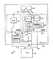
図1は、試験モード動作を有するトランシーバ120を含むトランシーバシステム100の実施例を示すブロックダイアグラムである。図1に示されているように、トランシーバ120には、ホスト110が接続されている。トランシーバ120には、送信機122、受信機124、コントローラ126、及び光インターフェイス128が含まれている。送信機122には、レーザ130、メモリ134、インターフェイス136、変調器及びバイアスD/Aコンバータ(DAC)138、及びフラグ146が含まれている。受信機124には、A/Dコンバータ(ADC)140が含まれている。コントローラ126には、ファームウェア142とメモリ144が含まれている。
FIG. 1 is a block diagram illustrating an embodiment of a
ホスト110は、トランシーバ120と共に動作するべく構成された有線又は無線装置であれば、どのようなタイプのものであってもよい。ホスト110は、トランシーバ120の外付けになっている。このような装置の例には、試験システム、サーバーコンピュータシステム、パーソナルコンピュータシステム、ラップトップコンピュータシステム、携帯コンピュータシステム、携帯情報端末、及び携帯電話が含まれる。
トランシーバ120は、以下に詳述するように、電気信号を送受信することによってホスト110と通信するべく構成された光トランシーバを備える。又、トランシーバ120は、光インターフェイス128を使用して光信号を送受信することにより、別の装置(図示されてはいない)とも通信する。光インターフェイス128は、ファイバチャネルインターフェイスやその他のタイプの光インターフェイスであってよい。
一実施例においては、トランシーバ120は、SFF(Small Form Factor)委員会が規定する光トランシーバ用のディジタル診断監視インターフェイスに関するSFF−8472規格に準拠している。その他の実施例においては、トランシーバ120は、その他の規格に準拠したものであってよい。
In one embodiment, the
送信機122は、動作上、接続152を使用してホスト110からディジタル出力信号を受信するべく構成された光送信機を備える。変調器及びバイアスDAC138により、このディジタル出力信号がアナログ出力信号に変換され、このアナログ出力信号がレーザ130に供給される。これらのディジタル出力信号及びアナログ出力信号は、電気信号を含む。レーザ130は、このアナログ出力信号に応答して光出力信号を生成し、この光出力信号が接続154を使用して光インターフェイス128に供給される。
受信機124は、接続156を使用して光インターフェイス128から光入力信号を受信するべく構成された光受信機を備える。A/Dコンバータ140により、この光入力信号がアナログ入力信号からディジタル入力信号に変換され、このディジタル入力信号が接続158によってホスト110に供給される。これらのディジタル出力信号及びアナログ出力信号は、電気信号を含む。
トランシーバ120は、電気的接続160を使用してホスト110とも通信する。具体的には、トランシーバ120は、接続160を使用してホスト110から制御信号を受信する。更に、トランシーバ120は、接続160を使用してホスト110に情報を提供する。図1の実施例において、電気的接続160は、ホスト110を送信機122に接続しており、この接続は、http://www.semiconductors.philips.com/acrobat/various/I2C_BUS_SPECIFICATION_3.pdfに存在するフィリップス半導体社(Philips Semiconductors)が提供するI2Cバス規格によって提供されるI2C接続であり、インターフェイス136は、I2Cバスインターフェイスから構成されている。更に、接続160及びインターフェイス136は、http://www.atmel.com/atmel/acrobat/doc0180.pdfに存在するアトメル社(Atmel)が提供するATMEL AT24C01A/02/04データシートによって提供されるATMEL AT24C01A/02/04ファミリー構成要素用に定義された2線シリアルCMOS EEPROMプロトコルに準拠している。
インターフェイス136は、ハードウェア、或いはハードウェア及びソフトウェア構成要素の組み合わせを備え得る。メモリ134は、情報を保存するべく構成されたどのようなタイプの揮発性又は不揮発性メモリであってもよい。図1の実施例においては、メモリ134はSRAMで構成されている。
コントローラ126は、接続164を使用して送信機122及び受信機124に制御信号を供給すると共に、これらからフィードバック信号を受信する。図1の実施例においては、接続164は、http://www.semiconductors.philips.com/acrobat/various/I2C_BUS_SPECIFICATION_3.pdfに存在するフィリップス半導体社(Philips Semiconductors)が提供するI2Cバス規格によって提供される内部I2C接続であり、コントローラ126はマスタとして機能し、送信機122及び受信機124はスレーブとして機能する。その他の実施例においては、接続164は、その他のどのようなタイプのシリアル又はパラレル接続であってもよい。
コントローラ126には、制御信号を生成しフィードバック信号を受信並びに処理するべくコントローラ126が実行可能なファームウェア142が含まれている。その他の実施例においては、コントローラ126は、本明細書で説明する機能を実行するべく、その他のハードウェア及び/又はファームウェア又はソフトウェアの組み合わせを含むことができる。メモリ144は、レジスタ、フラッシュメモリ、RAM、又はEEPROMを含むどのようなタイプの揮発性及び不揮発性記憶装置、或いは、それらの組み合わせであってもよい。
トランシーバ120の動作モードには、試験モードと顧客モードという少なくとも2つのものが含まれている。いずれのモードにおいても、トランシーバ120は、ホスト110と共に動作する。試験モード動作においては、ホスト110は、トランシーバ120に対して較正段階を実行する。この較正段階には、トランシーバ120に情報を保存する段階と、送信機122、受信機124、及びトランシーバ120のその他の構成要素を較正及び又は調整する段階と、が含まれる。保存する情報には、製造情報、生産情報、装置情報、レビジョン情報、レーザ130の較正定数を含む送信機122の設定及びパラメータ、OMA(optical modulation amplitude)テーブルを含む受信機124の設定及びパラメータ、クロック情報、温度係数情報、温度/Vcc較正定数、及びEEPROM情報が含まれる。
The operation modes of the
試験モード動作においては、トランシーバ120は、トランシーバ120の構成要素に対して自己試験を実行し、それぞれの構成要素の機能とレビジョン情報を検証することができる。更に、トランシーバ120は、レジスタの内容などの状態情報をトランシーバ120の構成要素からホスト110に供給する。更に、試験モード動作において、トランシーバ120は、内部監視タスクを実行可能である。
In test mode operation,
試験モード動作においては、トランシーバ120は、ホスト110からの要求に応答して較正段階を実行する。ホスト110は、インターフェイス136を使用し、較正段階に関連する要求をトランシーバ120に出す。この要求には、コマンド、アドレス、コマンドに関連する情報が含まれ、コントローラ126に関連する装置アドレスも含まれる。インターフェイス136は、接続161を使用し、この要求をメモリ134内に保存する。この要求に応答し、インターフェイス136は、要求を受信したことをコントローラ126に通知するフラグ146を接続162を使用して設定する。コントローラ126は、接続163を使用して定期的にフラグ146をポーリングし、インターフェイス136によってフラグ146が設定されたと判定した際に、コントローラ126は、接続164を使用してメモリ134内の要求にアクセスする。
In test mode operation,
コントローラ126は、要求に関連する較正段階を実行することにより、その要求を処理する。そして、その較正段階が完了すると、コントローラ126は、その段階が実行されたことを示す標識をメモリ144に保存する。又、コントローラ126は、接続164を使用してメモリ134内に、この標識を保存し、接続163を使用してフラグ146をクリアすることにより、ホスト110に対しても標識を供給する。インターフェイス136は、フラグ146のクリアを検出するか、或いは、メモリ134への保存を監視することにより、メモリ134内の標識を検出する。この標識の検出に応答し、インターフェイス136は、標識をホスト110に供給する。ホスト110は、この標識をメモリ(図示されてはいない)に保存する。次いで、ホスト110は、更なる較正段階を上述のように同様に実行することができる。
コントローラ126は、較正段階を完了するごとに、コントローラ126が、メモリ144内の情報にアクセスし、すべての較正段階が完了しているかどうかを判定する。この情報には、それぞれの段階が成功裏に完了しているかどうかを示すそれぞれの較正段階に関連する標識が含まれている。ある段階が実行されていないか、或いは、成功裏に実行されていない場合には、コントローラ126は、トランシーバ120を試験モード動作に保持する。そして、すべての段階が成功裏に実行されている場合に、コントローラ126は、トランシーバ120を顧客モード動作に設定する。
Each
ホスト110は、それぞれの較正段階ごとにトランシーバ120から受信する標識によっても、すべての較正段階が成功裏に完了したかどうかを判定することができる。この標識は、それぞれの較正段階が成功裏に完了したかどうか、並びにエラーが発生したかどうかを示している。又、ホスト110は、トランシーバ120を試験モード動作から離脱させる要求をトランシーバ120に出すこともできる。この試験モード離脱要求に応答し、トランシーバ120は、トランシーバ120に対して実行した較正段階の中のどれが成功裏に完了しなかったのかを示す標識を供給する(成功裏に完了しなかった較正段階が存在する場合)。1つ又は複数の較正段階が成功裏に完了しなかったと判定した場合には、ホスト110は、トランシーバ120に対して故障解析機能を実行することができる。すべての較正段階が成功裏に完了したと判定された場合には、ホスト110は、トランシーバ120の顧客又はエンドユーザに対する出荷準備が完了したと判定可能である。
The
顧客モード動作においては、トランシーバ120は、通常、ホスト110と共に動作する。具体的には、トランシーバ120は、ホスト110から電気信号を受信し、この電気信号を光信号に変換し、この光信号を光インターフェイス128を使用して別の装置(図示されてはいない)に供給する。更に、トランシーバ120は、光インターフェイス128を介してその他の装置から光信号を受信し、この光信号を電気信号に変換し、この電気信号をホスト110に供給する。顧客モード動作では、いずれの時点においても、ホスト110は、試験モードの設定要求をトランシーバ120に対して出すことにより、トランシーバ120を試験モード動作に再設定することができる。
In customer mode operation,
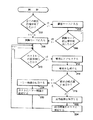
図2は、トランシーバの動作モードを変更する方法の実施例を示すフローチャートである。以下、図1を参照し、図2の方法の実施例について説明する。図2のブロック202に示されているように、コントローラ126は、トランシーバ120のすべての較正段階が完了しているかどうかを判定する。この判定は、トランシーバ120の電源投入(即ち、スイッチオン)又はリセットに応答して実行可能である。
FIG. 2 is a flowchart illustrating an embodiment of a method for changing an operation mode of a transceiver. Hereinafter, an embodiment of the method of FIG. 2 will be described with reference to FIG. As shown in
トランシーバ120のすべての較正段階が完了している場合には、トランシーバ120は、ブロック204に示されているように、顧客モード動作に入る。次いで、ブロック206に示されているように、ホスト110からの試験モード設定要求をコントローラ126が検出するかどうかを判定する。そして、コントローラ126が試験モード設定要求を検出した場合には、トランシーバは、ブロック208に示されているように、試験モード動作に入る。
If all calibration steps for
トランシーバ120のすべての較正段階が完了していない場合には、トランシーバ120は、ブロック208に示されているように、試験モード動作に入る。次いで、ブロック210に示されているように、ホスト110からの要求をコントローラ126が検出しているかどうかを判定する。コントローラ126は、フラグ146をポーリングすることにより、要求を検出することができる。そして、コントローラ126がホスト110からの要求を検出していない場合には、この方法では、ブロック210の機能を再度反復実行する。コントローラ126がホスト110からの要求を検出している場合には、コントローラ126は、ブロック212に示されているように、その要求にアクセスする。コントローラ126は、メモリ134に存在する要求にアクセスする。そして、コントローラ126は、ブロック214に示されているように、その要求を処理する。
If all of the calibration steps for
ブロック216に示されているように、要求が成功裏に完了したかどうかを判定する。そして、要求が成功裏に完了しなかった場合には、コントローラ126は、ブロック218に示されているように、エラー標識をメモリ144内に保存する。又、コントローラ126は、ブロック220に示されているように、ホスト110に対してもエラー標識を供給する。このエラー標識は、メモリ134及びインターフェイス136を使用してホスト110に供給される。
As shown at
要求が成功裏に完了している場合には、コントローラ126は、ブロック222に示されているように、メモリ144内に成功標識を保存する。又、コントローラ126は、ブロック224に示されているように、ホスト110に対しても成功標識を供給する。この成功標識は、メモリ134及びインターフェイス136を使用してホスト110に供給される。
If the request has been successfully completed, the
図3は、試験モード動作のトランシーバとやり取りする方法の実施例を示すフローチャートである。以下、図1を参照し、図3の方法の実施例について説明する。図3のブロック302に示されているように、ホスト110は、要求をトランシーバ120に対して出す。この要求は、較正段階の実行要求、又は試験モードの設定要求である。試験モードの設定要求により、トランシーバ120は試験モード動作に入り、較正段階の実行要求により、トランシーバ120に対してその較正段階が実行される。ブロック304に示されているように、ホスト110は、この要求に関連する標識を受信したかどうかを判定する。そして、ホスト110が、要求に関連する標識を受信していない場合には、ホスト110は、ブロック306に示されているように、トランシーバ120に関連するエラー状態を検出し、この方法は終了する。トランシーバ120は、較正段階の成功/不成功に関係なく、較正段階の実行に応答して標識を供給するように構成されているため、ホスト110が標識を受信しない場合には、エラー状態と見なすことができるのである。
FIG. 3 is a flowchart illustrating an embodiment of a method for interacting with a transceiver in test mode operation. Hereinafter, an embodiment of the method of FIG. 3 will be described with reference to FIG. Host 110 issues a request to
ホスト110が要求に関連する標識を受信している場合には、ホスト110は、ブロック308に示されているように、この標識を保存する。次いで、ブロック310に示されているように、ホスト110は、実行を要する更なる較正段階が存在するかどうかを判定する。そして、実行を要する更なる較正段階が存在する場合には、この方法では、ブロック302の機能を反復実行する。実行を要する更なる較正段階が存在しない場合には、この方法は終了する。
If the
図4は、トランシーバの試験モード動作からエラーを検出する方法の実施例を示すフローチャートである。以下、図1を参照し、図4の方法の実施例について説明する。図4のブロック402に示されているように、ホスト110は、較正段階で保存された標識をチェックする。次いで、ブロック404に示されているように、ホスト110は、それらの標識を使用し、エラーが検出されているかどうかを判定する。そして、エラーが検出されている場合には、ホスト110は、ブロック406に示されているように、故障の発生したトランシーバ120を解析し、この方法は終了する。エラーが検出されていない場合には、ホスト110は、ブロック308に示されているように、トランシーバ120の出荷準備が完了したことを示す。
FIG. 4 is a flowchart illustrating an embodiment of a method for detecting an error from a test mode operation of a transceiver. Hereinafter, an embodiment of the method of FIG. 4 will be described with reference to FIG. As shown in
図4の別の実施例においては、ホスト110は、較正段階に関連する標識が保存された際に、即時にエラーを検出することができる。このエラーに応答し、ホスト110は、故障の修復を試みるか、或いは、故障の発生したトランシーバ120に対して1つ又は複数の故障解析機能を実行することができる。
In the alternative embodiment of FIG. 4, the
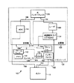
図5は、試験モード動作を有するトランシーバを含むトランシーバシステムの別の実施例を示すブロックダイアグラムである。図5の実施例は、図2〜図4を参照して説明した図1の実施例と略同様に動作する。しかしながら、図5の場合には、キャッシュ134とインターフェイス136が送信機122には含まれていない。この実施例は、トランシーバ120のその他の部分又は構成要素にキャッシュ134とインターフェイス136を含むことができることを示すものである。
FIG. 5 is a block diagram illustrating another embodiment of a transceiver system including a transceiver having test mode operation. The embodiment of FIG. 5 operates in substantially the same manner as the embodiment of FIG. 1 described with reference to FIGS. However, in the case of FIG. 5, the cache 134 and the
本明細書においては、好適な実施例を説明するべく、特定の実施例について例示し説明しているが、当業者であれば、本発明の範囲を逸脱することなく、同一の目的を実現するべく適合された様々な代替及び/又は等価実施例により、これらの例示及び説明した特定の実施例を置換可能であることを理解するであろう。化学、機械、電気機械、電気、及びコンピュータ分野における知識を有する者であれば、本発明が、一部を下記するが、様々な実施態様で実施可能であることを容易に理解するであろう。本出願は、本明細書において説明した好適な実施例のあらゆる適合や変形を包含するものである。従って、本発明を限定するものは、特許請求の範囲及びその等価物のみである。 Although specific embodiments have been illustrated and described herein in order to describe the preferred embodiments, those skilled in the art will achieve the same objects without departing from the scope of the invention. It will be understood that various alternative and / or equivalent embodiments adapted to that may replace these particular embodiments described and illustrated. Those with knowledge in the chemical, mechanical, electromechanical, electrical, and computer arts will readily appreciate that the present invention can be implemented in various embodiments, some of which are described below. . This application is intended to cover any adaptations or variations of the preferred embodiment discussed herein. Accordingly, the invention is limited only by the following claims and their equivalents.
(実施態様1):ホスト(110)と、前記ホスト(110)に接続されたトランシーバ(120)と、を有し、前記トランシーバは、ホストから第1要求を受信するべく構成されると共に、前記トランシーバは、前記第1要求の受信に応答し、試験モード動作に入るべく構成されていることを特徴とするトランシーバシステム。 (Embodiment 1): A host (110) and a transceiver (120) connected to the host (110), wherein the transceiver is configured to receive a first request from a host, and The transceiver system, wherein the transceiver is configured to enter a test mode operation in response to receiving the first request.
(実施態様2):前記トランシーバが、前記試験モード動作に入る前に、顧客モード動作で動作することを特徴とする実施態様1に記載のトランシーバシステム。 (Embodiment 2): The transceiver system according to embodiment 1, wherein the transceiver operates in a customer mode operation before entering the test mode operation.
(実施態様3):前記トランシーバは、前記ホストから第2要求を受信するべく構成されると共に、前記トランシーバは、前記第2要求の受信に応答し、較正段階を実行するべく構成されていることを特徴とする実施態様1に記載のトランシーバシステム。 (Embodiment 3): The transceiver is configured to receive a second request from the host, and the transceiver is configured to perform a calibration step in response to receiving the second request. The transceiver system according to embodiment 1, wherein the transceiver system comprises:
(実施態様4):前記較正段階が、前記ホストから受信した情報を前記トランシーバ内に保存する段階を有することを特徴とする実施態様3に記載のトランシーバシステム。 Embodiment 4: The transceiver system of embodiment 3, wherein the calibrating step comprises storing information received from the host in the transceiver.
(実施態様5):コントローラ(126)と、前記コントローラに接続され、第1情報を含む第1メモリ(144)と、を有し、前記コントローラは、前記第1情報にアクセスするべく構成されると共に、前記コントローラは、較正段階が完了していないことを示す前記第1情報に応答し、試験モード動作に入るべく構成されていることを特徴とするトランシーバ。 (Embodiment 5): A controller (126) and a first memory (144) connected to the controller and containing first information, wherein the controller is configured to access the first information. And wherein the controller is configured to enter a test mode operation in response to the first information indicating that a calibration step has not been completed.
(実施態様6):前記コントローラは、電源投入に応答し、前記第1情報にアクセスするべく構成されていることを特徴とする実施態様5に記載のトランシーバ。 Embodiment 6: The transceiver according to embodiment 5, wherein the controller is configured to access the first information in response to power-on.
(実施態様7):前記コントローラは、前記較正段階が完了していることを示す前記第1情報に応答し、顧客モード動作に入るべく構成されていることを特徴とする実施態様5に記載のトランシーバ。 Embodiment 7: The controller of embodiment 5, wherein the controller is responsive to the first information indicating that the calibration step is completed and is configured to enter customer mode operation. Transceiver.
(実施態様8):前記コントローラは、前記較正段階に関連する要求をホスト(110)から受信するべく構成されると共に、前記コントローラは、前記要求の受信に応答し、前記第1較正段階を実行するべく構成されていることを特徴とする実施態様5に記載のトランシーバ。 Embodiment 8: The controller is configured to receive a request related to the calibration step from a host (110), and the controller performs the first calibration step in response to receiving the request. 6. The transceiver of embodiment 5, wherein the transceiver is configured to:
(実施態様9):前記コントローラは、前記第1較正段階の実行に応答し、顧客モード動作に入るべく構成されていることを特徴とする実施態様8に記載のトランシーバ。 Embodiment 9: The transceiver of embodiment 8, wherein the controller is configured to enter customer mode operation in response to performing the first calibration step.
(実施態様10):前記コントローラは、前記較正段階に関連するエラーの検出に応答し、標識を前記ホストに供給するべく構成されていることを特徴とする実施態様8に記載のトランシーバ。 Embodiment 10: The transceiver of embodiment 8, wherein the controller is configured to provide an indication to the host in response to detecting an error associated with the calibration step.
(実施態様11):前記コントローラは、前記較正段階が成功裏に完了したことを検出した際に、標識を前記ホストに供給するべく構成されていることを特徴とする実施態様8に記載のトランシーバ。 Embodiment 11: The transceiver of embodiment 8, wherein the controller is configured to provide an indicator to the host upon detecting that the calibration step has been successfully completed. .
110 ホスト
120 トランシーバ
126 コントローラ
144 第1メモリ
110
Claims (1)
前記ホストに接続されたトランシーバと、を有し、
前記トランシーバは、前記ホストから第1要求を受信し、前記第1要求の受信に応答し試験モード動作に入ることを特徴とするトランシーバシステム。 Host and
A transceiver connected to the host,
The transceiver system, wherein the transceiver receives a first request from the host, and enters a test mode operation in response to receiving the first request.
Applications Claiming Priority (1)
| Application Number | Priority Date | Filing Date | Title |
|---|---|---|---|
| US10/346,480 US7668512B2 (en) | 2003-01-15 | 2003-01-15 | Transceiver with a test mode of operation |
Publications (2)
| Publication Number | Publication Date |
|---|---|
| JP2004222299A true JP2004222299A (en) | 2004-08-05 |
| JP2004222299A5 JP2004222299A5 (en) | 2007-02-22 |
Family
ID=29735986
Family Applications (1)
| Application Number | Title | Priority Date | Filing Date |
|---|---|---|---|
| JP2004007272A Withdrawn JP2004222299A (en) | 2003-01-15 | 2004-01-14 | Transceiver system |
Country Status (3)
| Country | Link |
|---|---|
| US (1) | US7668512B2 (en) |
| JP (1) | JP2004222299A (en) |
| GB (1) | GB2398466B (en) |
Families Citing this family (15)
| Publication number | Priority date | Publication date | Assignee | Title |
|---|---|---|---|---|
| US7463674B2 (en) * | 2003-04-09 | 2008-12-09 | Avago Technologies Fiber Ip (Singapore) Pte. Ltd. | Tables for determining the signal strength of a received signal in a fibre optics transceiver |
| TWI244278B (en) | 2004-06-04 | 2005-11-21 | Ind Tech Res Inst | Optical transceiver module |
| US7471897B1 (en) | 2004-07-16 | 2008-12-30 | Cisco Technology, Inc. | Electrically looped back, fault emulating transceiver module |
| US8131223B2 (en) * | 2006-04-14 | 2012-03-06 | Litepoint Corporation | System for testing an embedded wireless transceiver |
| US7689213B2 (en) * | 2006-04-14 | 2010-03-30 | Litepoint Corp. | Method for testing embedded wireless transceiver with minimal interaction between wireless transceiver and host processor during testing |
| US7865147B2 (en) * | 2006-04-14 | 2011-01-04 | Litepoint Corporation | System for testing an embedded wireless transceiver |
| US8676188B2 (en) * | 2006-04-14 | 2014-03-18 | Litepoint Corporation | Apparatus, system and method for calibrating and verifying a wireless communication device |
| US8903374B2 (en) * | 2008-05-28 | 2014-12-02 | Apple Inc. | System for calibrating wireless communications devices |
| JP2009290022A (en) * | 2008-05-29 | 2009-12-10 | Fujitsu Ltd | Optical transceiver |
| US7974537B2 (en) * | 2008-06-05 | 2011-07-05 | Finisar Corporation | Intelligent pluggable transceiver stick capable of diagnostic monitoring and optical network management |
| US8437793B2 (en) * | 2009-11-24 | 2013-05-07 | Apple Inc. | Wireless transmitter calibration using absolute power requests |
| US8837934B2 (en) * | 2011-08-30 | 2014-09-16 | Avago Technologies General Ip (Singapore) Pte. Ltd. | Monitoring circuitry for optical transceivers |
| US9910819B2 (en) * | 2013-03-11 | 2018-03-06 | Microchip Technology Incorporated | Two-wire serial interface and protocol |
| US9450854B2 (en) | 2013-03-14 | 2016-09-20 | Exfo Inc. | Pass-through test device |
| US9838138B1 (en) * | 2015-12-30 | 2017-12-05 | Juniper Networks, Inc. | Self-calibration of pluggable optical module |
Family Cites Families (46)
| Publication number | Priority date | Publication date | Assignee | Title |
|---|---|---|---|---|
| FR2455827A1 (en) | 1979-05-03 | 1980-11-28 | Ibm France | DIAGNOSTIC AND ALARM DEVICE FOR A DATA COMMUNICATION NETWORK |
| US4449247A (en) | 1980-07-30 | 1984-05-15 | Harris Corporation | Local orderwire facility for fiber optic communication system |
| US4918623A (en) | 1985-10-04 | 1990-04-17 | Codex Corporation | Testing the performance of a communication line between two modems using modem processor |
| JPH0273682A (en) | 1988-09-08 | 1990-03-13 | Nippon Digital Equip Kk | Laser diode driving method and device |
| US4945229A (en) | 1988-12-29 | 1990-07-31 | Thomas & Betts Corporation | Fiber optic receiver and transceiver |
| DE68914151T2 (en) | 1989-08-11 | 1994-07-07 | Hewlett Packard Co | Network transmitter-receiver. |
| US5255086A (en) * | 1990-03-20 | 1993-10-19 | Scientific-Atlanta, Inc. | Method and apparatus for RF data transfer in a CATV system |
| US5019769A (en) | 1990-09-14 | 1991-05-28 | Finisar Corporation | Semiconductor laser diode controller and laser diode biasing control method |
| US5345230A (en) | 1992-04-13 | 1994-09-06 | Dr. Johannes Heidenhain Gmbh | Method and apparatus for optical transceiver testing |
| IL114727A (en) * | 1995-07-25 | 1998-06-15 | Jolt Ltd | System and method for wirelessly communicating a sound signal |
| US6446867B1 (en) | 1995-11-22 | 2002-09-10 | Jorge Sanchez | Electro-optic interface system and method of operation |
| US5812572A (en) * | 1996-07-01 | 1998-09-22 | Pacific Fiberoptics, Inc. | Intelligent fiberoptic transmitters and methods of operating and manufacturing the same |
| US5953690A (en) * | 1996-07-01 | 1999-09-14 | Pacific Fiberoptics, Inc. | Intelligent fiberoptic receivers and method of operating and manufacturing the same |
| US5970430A (en) * | 1996-10-04 | 1999-10-19 | Fisher Controls International, Inc. | Local device and process diagnostics in a process control network having distributed control functions |
| US5953372A (en) * | 1996-12-13 | 1999-09-14 | Standard Microsystems Corporation | Loopback transmission testing in a communications device |
| US6253060B1 (en) | 1996-12-20 | 2001-06-26 | Airnet Communications Corporation | Method and apparatus employing wireless remote loopback capability for a wireless system repeater to provide end-to-end testing without a wireline connection |
| US6201820B1 (en) | 1997-03-05 | 2001-03-13 | Silkroad, Inc. | Optically modulated laser beam transceiver |
| JP3315892B2 (en) | 1997-04-24 | 2002-08-19 | 沖電気工業株式会社 | Laser module control circuit |
| KR100245799B1 (en) * | 1997-06-30 | 2000-03-02 | 윤종용 | A system and a method for automatically creating and transmitting test conditions of integrated circuit devices |
| US6512617B1 (en) * | 1998-02-03 | 2003-01-28 | Applied Micro Circuits Corporation | Methods and systems for control and calibration of VCSEL-based optical transceivers |
| US6201829B1 (en) * | 1998-04-03 | 2001-03-13 | Adaptec, Inc. | Serial/parallel GHZ transceiver with pseudo-random built in self test pattern generator |
| US6216095B1 (en) | 1998-10-23 | 2001-04-10 | Westinghouse Air Brake Technologies Corporation | Automated in situ testing of railroad telemetry radios |
| JP3654069B2 (en) * | 1998-10-27 | 2005-06-02 | 富士通株式会社 | Optical storage medium, processing method therefor, and optical storage medium processing apparatus |
| US6256483B1 (en) * | 1998-10-28 | 2001-07-03 | Tachyon, Inc. | Method and apparatus for calibration of a wireless transmitter |
| US6424630B1 (en) | 1998-10-30 | 2002-07-23 | Advanced Micro Devices, Inc. | Apparatus and method for calibrating a home networking station receiving network signals on a telephone line medium |
| US6549310B1 (en) * | 1999-01-08 | 2003-04-15 | International Business Machines Corporation | Fiber optic data link module with built-in link diagnostics |
| US6599038B1 (en) | 1999-01-08 | 2003-07-29 | Priority Electronics, Inc. | Passive remote loop-back method and apparatus for optical circuit verification |
| JP3574580B2 (en) | 1999-01-14 | 2004-10-06 | ペンタックス株式会社 | Semiconductor laser device |
| US7149473B1 (en) * | 1999-01-15 | 2006-12-12 | Nokia Corporation | Interface |
| CA2363753A1 (en) * | 1999-03-05 | 2000-09-08 | International Truck And Engine Corporation | Telemetry system and method for emi susceptibility testing of motor vehicles |
| US6832075B1 (en) | 1999-10-05 | 2004-12-14 | Ericsson Inc. | Method for calibrating the power output of a mobile device |
| US6407402B1 (en) * | 1999-10-28 | 2002-06-18 | Powersmart, Inc. | I2C opto-isolator circuit |
| US20020027688A1 (en) * | 2000-09-05 | 2002-03-07 | Jim Stephenson | Fiber optic transceiver employing digital dual loop compensation |
| US6590644B1 (en) * | 2001-01-12 | 2003-07-08 | Ciena Corporation | Optical module calibration system |
| US6687642B2 (en) * | 2001-01-26 | 2004-02-03 | Texas Instruments Incorporated | Condition responsive sense system and method |
| US7079775B2 (en) * | 2001-02-05 | 2006-07-18 | Finisar Corporation | Integrated memory mapped controller circuit for fiber optics transceiver |
| US6975642B2 (en) * | 2001-09-17 | 2005-12-13 | Finisar Corporation | Optoelectronic device capable of participating in in-band traffic |
| US20030113118A1 (en) * | 2001-11-28 | 2003-06-19 | Meir Bartur | Smart single fiber optic transceiver |
| US7603468B2 (en) * | 2002-01-14 | 2009-10-13 | Agere Systems, Inc. | Home adaptive transceiver for home networking communication system |
| US7242862B2 (en) * | 2002-01-21 | 2007-07-10 | Altera Corporation | Network diagnostic tool for an optical transport network |
| US7088969B2 (en) * | 2002-02-12 | 2006-08-08 | Broadcom Corporation | Highly linear power amplifier and radio applications thereof |
| US7155133B2 (en) * | 2002-02-12 | 2006-12-26 | Finisar Corporation | Avalanche photodiode controller circuit for fiber optics transceiver |
| US6947455B2 (en) * | 2002-02-12 | 2005-09-20 | Finisar Corporation | Maintaining desirable performance of optical emitters at extreme temperatures |
| US7269191B2 (en) | 2002-02-12 | 2007-09-11 | Finisar Corporation | Control circuit for optoelectronic module with integrated temperature control |
| TW569013B (en) * | 2002-02-21 | 2004-01-01 | Via Tech Inc | Chip test method for testing host controller of universal serial bus |
| US7206710B2 (en) * | 2005-01-14 | 2007-04-17 | Verigy Pte. Ltd. | Incremental generation of calibration factors for automated test equipment |
-
2003
- 2003-01-15 US US10/346,480 patent/US7668512B2/en not_active Expired - Fee Related
- 2003-11-10 GB GB0326164A patent/GB2398466B/en not_active Expired - Fee Related
-
2004
- 2004-01-14 JP JP2004007272A patent/JP2004222299A/en not_active Withdrawn
Also Published As
| Publication number | Publication date |
|---|---|
| GB2398466B (en) | 2005-06-08 |
| US20040203443A1 (en) | 2004-10-14 |
| GB0326164D0 (en) | 2003-12-17 |
| US7668512B2 (en) | 2010-02-23 |
| GB2398466A (en) | 2004-08-18 |
Similar Documents
| Publication | Publication Date | Title |
|---|---|---|
| JP2004222297A (en) | Transceiver | |
| JP2004222299A (en) | Transceiver system | |
| US7107414B2 (en) | EEPROM emulation in a transceiver | |
| US20070055793A1 (en) | System of managing peripheral interfaces in IPMI architecture and method thereof | |
| US7822964B2 (en) | Booting apparatus for booting a computer and method therefor and computer with a booting apparatus | |
| JP2003039778A (en) | Peripheral apparatus and printer | |
| US6219451B1 (en) | Method and apparatus for counter based liquid crystal display panel identification for a computer | |
| US20170337066A1 (en) | Computer and controlling method thereof | |
| US20200142756A1 (en) | Adapter with instrument control function, instrument control system and instrument control method | |
| US7587294B2 (en) | SATA device having self-test function for OOB-signaling | |
| US20120251124A1 (en) | Transceiver for different vendor devices | |
| US7945714B2 (en) | Apparatus and method of tracing descriptors in host controller | |
| US8291270B2 (en) | Request processing device, request processing system, and access testing method | |
| CN1983195A (en) | Mounting device, electronic device, method of controlling mounting device, controlling program, and recording medium | |
| CN116126613A (en) | Position detection method and device of PCIe (peripheral component interconnect express) equipment, electronic equipment and storage medium | |
| US20140292384A1 (en) | Methods of multi-protocol system and integrated circuit for multi-protocol communication on single wire | |
| US6530048B1 (en) | I2C test single chip | |
| US20220027300A1 (en) | USB hub device having functionality of self firmware updating and host electronic system having the same | |
| US11204593B2 (en) | Control device and adjustment method | |
| US20170099401A1 (en) | Information processing apparatus, information processing system, method of controlling the information processing apparatus, and storage medium | |
| US11843612B2 (en) | Communication device management device, system, method, and non-transitory computer-readable recording medium | |
| CN115097879B (en) | Temperature regulation and control method, device, equipment and medium | |
| US11151340B2 (en) | RFID tag and RFID tag system | |
| CN110275808B (en) | System, method and server for detecting ID conflict of transfer card | |
| US9052849B1 (en) | Method and apparatus for dynamically adapting a printing appliance to a printer |
Legal Events
| Date | Code | Title | Description |
|---|---|---|---|
| A521 | Request for written amendment filed |
Free format text: JAPANESE INTERMEDIATE CODE: A523 Effective date: 20070109 |
|
| A621 | Written request for application examination |
Free format text: JAPANESE INTERMEDIATE CODE: A621 Effective date: 20070109 |
|
| A711 | Notification of change in applicant |
Free format text: JAPANESE INTERMEDIATE CODE: A711 Effective date: 20070320 |
|
| RD03 | Notification of appointment of power of attorney |
Free format text: JAPANESE INTERMEDIATE CODE: A7423 Effective date: 20070411 |
|
| A761 | Written withdrawal of application |
Free format text: JAPANESE INTERMEDIATE CODE: A761 Effective date: 20070501 |