JP2004221992A - Imaging device and program - Google Patents
Imaging device and program Download PDFInfo
- Publication number
- JP2004221992A JP2004221992A JP2003007608A JP2003007608A JP2004221992A JP 2004221992 A JP2004221992 A JP 2004221992A JP 2003007608 A JP2003007608 A JP 2003007608A JP 2003007608 A JP2003007608 A JP 2003007608A JP 2004221992 A JP2004221992 A JP 2004221992A
- Authority
- JP
- Japan
- Prior art keywords
- image
- shooting
- photographing
- exposure
- imaging
- Prior art date
- Legal status (The legal status is an assumption and is not a legal conclusion. Google has not performed a legal analysis and makes no representation as to the accuracy of the status listed.)
- Pending
Links
Images


Landscapes
- Adjustment Of Camera Lenses (AREA)
- Studio Devices (AREA)
Abstract
Description
【0001】
【発明の属する技術分野】
本発明は、手振れを補正することで撮影画像の精度を向上させる撮影装置に関するものである。
【0002】
【従来の技術】
現在のカメラは露出決定やピント合わせ等の撮影にとって重要な作業は全て自動化され、カメラ操作に未熟な人でも撮影失敗を起こす可能性は非常に少なくなっている。
【0003】
また、最近では、カメラに加わる手振れを防ぐシステムも研究されており、撮影者の撮影ミスを誘発する要因は殆ど無くなってきている。
【0004】
ここで、手振れを防ぐ防振システムについて簡単に説明する。
【0005】
撮影時のカメラの手振れは、周波数として通常1Hzないし10Hzの振動であるが、露光時点においてこのような手振れを起こしていても像振れの無い写真を撮影可能とするための基本的な考えとして、手振れによるカメラの振動を検出し、この検出結果に応じて補正レンズを光軸直交面内で変位させなければならない(光学防振システム)。
【0006】
すなわち、カメラ振れが生じても像振れが生じない写真を撮影するためには、第1にカメラの振動を正確に検出し、第2に手振れによる光軸変化を補正することが必要となる。
【0007】
像振れの補正は、原理的には、レーザージャイロ等により加速度、角加速度、角速度、角変位等を検出し、この検出結果に対して適宜演算処理する振動検出部をカメラに搭載することによって行うことができる。そして、振動検出部からのカメラ振れの検出情報に基づき撮影光軸を偏心させる振れ補正光学装置(補正レンズを含む)を駆動することにより像振れ補正が行われる。
【0008】
一方、手振れが生じない程度の露光時間で複数回撮影を繰り返し、これらの撮影により得られた画像に対して画像のズレを修正しながら合成して長い露光時間の撮影画像(合成画像)を得る方法がある(例えば、特許文献1)。
【0009】
【特許文献1】
特許第3110797号
【0010】
【発明が解決しようとする課題】
最近のデジタルカメラは、銀塩コンパクトカメラに比べて小さくなってきており、特にVGAクラスの撮像素子を持つカメラは携帯電子機器(例えば、携帯電話)に内蔵されるほど小型になってきている。
【0011】
このような中で、上述した光学防振システムをカメラに搭載しようとすると、振れ補正光学装置をよりいっそう小型化するか、振動検出部を小型化する必要がある。
【0012】
しかし、振れ補正光学装置では、補正レンズを支持し、これを高精度に駆動してゆく必要があるために小型化には限度がある。また、現在使用されている振動検出部は、ほとんどが慣性力を利用するものなので、振動検出部を小型化すると検出感度が低下し、精度の良い振れ補正ができないという問題がある。
【0013】
さらに、カメラに加わる振れとしては、所定の軸を中心とする角度振れと、カメラを平行に揺らすシフト振れがあり、角度振れは光学防振システムで補正可能であるがシフト振れ対策は困難である。特に、カメラが小型になるほどこのシフト振れは大きくなる傾向がある。
【0014】
一方、別の防振システムとしては、ビデオカメラでの動画撮影に用いられているように撮像素子で画面の動きベクトルを検出し、その動きベクトルに合わせて画像の読み出し位置を変更することで振れのない動画を得る方法もある。
【0015】
このような方法の場合には、上述した光学防振システムのような専用の振動検出部や補正レンズが不要となるため、製品全体を小型にできるメリットがある。
【0016】
しかし、このビデオカメラの防振システムをデジタルカメラに簡単に適用することはできない。この理由を以下に説明する。
【0017】
ビデオカメラにおける動きベクトルの抽出は画像を読み出すごとに行っており、例えば1秒に15コマの画像を取り出すとすると、この取り出した各画像を比較して動きベクトルを検出している。
【0018】
ところが、デジタルカメラで静止画を撮影する場合には、撮影被写体に対して1回の露光しか行わないため、ビデオカメラのように画像の比較を行って動きベクトルを検出することはできない。
【0019】
このため、ビデオカメラの防振システムを単純にデジタルカメラに適応させることはできない。
【0020】
一方、特許文献1に示すような防振方法においては、複数回撮影を繰り返すことから撮影時間が長期にわたることになる。このため、むやみにこの方法を使用すると被写体ブレなどの失敗写真がかえって多くなる恐れがある。
【0021】
そして、この防振方法を使用する条件に対してユーザーは常に考えている必要があリ、1回の露光で撮影を行う通常の撮影方法に比べて扱いにくいシステムになってしまう。以下、具体的に説明する。
【0022】
銀塩カメラと異なりデジタルカメラでは、撮像素子の感度(撮像感度)を自在に変更できる。このため、暗い被写体においても撮像感度を上げることで、ある程度の手振れを防ぐことができる。
【0023】
そして、撮像感度の設定は、カメラ任せ(自動設定)にもできるし、ユーザー自身が設定することもできる。
【0024】
このようにデジタルカメラでは、防振使用の必要性を判断するパラメータが銀塩カメラよりも多いため、本当に防振対策が必要か否かをユーザー自身が判断することは難しくなってきており、ユーザーにとって扱いにくいシステムになってしまう。
【0025】
また、上記の防振方法では、一回の撮影時に複数の露光が行われるために、ユーザーが違和感を感じるおそれがある。
【0026】
そこで、本発明の目的は、銀塩カメラの光学防振システムやビデオカメラの防振システムとは異なるデジタルカメラの静止画撮影向けの小型の防振システムを提供することにある。そして、手振れが生じない程度の露光時間で複数回撮影を繰り返し、この複数の撮影により得られた画像に対してズレを修正しながら合成して長い露光時間の撮影画像(合成画像)を得る方法をデジタルカメラに搭載した時においても、この動作をカメラが自動設定して撮影の失敗を未然に防ぐとともに、この扱い方に対してユーザーが違和感を感じない撮影装置を提供することにある。
【0027】
【課題を解決するための手段】
本願第1の発明は、順次撮影して得られた複数の画像を合成することにより、露出補正された合成画像を得る第1の撮影モードと、1回の撮影により合成画像に相当する画像を得る第2の撮影モードでの撮影が可能な撮影装置であって、 撮影時の撮影条件に応じて第1の撮影モードおよび第2の撮影モードのうち一方の撮影モードに設定可能な制御手段を有することを特徴とする。
【0028】
本願第2の発明は、順次撮影して得られた複数の画像を合成することにより、露出補正された合成画像を得る第1の撮影モードと、1回の撮影により合成画像に相当する画像を得る第2の撮影モードでの撮影を可能とするプログラムであって、撮影時の撮影条件に応じて第1の撮影モードおよび第2の撮影モードのうち一方の撮影モードに設定可能な制御ステップを有することを特徴とする。
【0029】
【発明の実施の形態】
(第1実施形態)
図1は、本発明の第1実施形態であるカメラ(撮影装置)の構成を示した図である。撮影レンズ11から入射した光束(撮影光)は、絞り13aで光量制限された後に、シャッタ12aを通り撮像部19で結像する。撮像部19は、MOSやCCDなどの半導体撮像素子からなる。
【0030】
撮影レンズ11は複数の光学レンズ群により構成され、これらのレンズ群のうち一部又は全部がAF駆動モータ14aからの駆動力を受けて光軸10上を移動し、所定の合焦位置に停止することで焦点調節を行う。AF駆動モータ14aは焦点駆動部14bからの駆動信号を受けることで駆動する。
【0031】
また、撮影レンズ11のうち一部の光学レンズ群は、ズーム駆動モータ15aからの駆動力を受けて光軸10上を移動し、所定のズーム位置に停止することで撮影画角を変更する。ズーム駆動モータ15aは、ズーム駆動部15bからの駆動信号を受けることで駆動する。
【0032】
絞り13aは、複数の絞り羽根を有しており、これらの絞り羽根は、絞り駆動部13bからの駆動力を受けることで作動して光通過口となる開口面積(絞り口径)を変化させる。シャッタ12aは、複数のシャッタ羽根を有しており、これらのシャッタ羽根は、シャッタ駆動部12aからの駆動力を受けることで光通過口となる開口部を開閉する。これにより、撮像部19に入射する光束を制御する。
【0033】
また、撮影時の条件(被写体輝度等)などに応じてストロボ16aは閃光駆動部16bからの駆動信号を受けて駆動(発光)する。
【0034】
さらに、撮影動作を撮影者に知らせるためにスピーカー17aが発音駆動部17bからの駆動信号を受けて駆動(発音)する。
【0035】
焦点駆動部14b、ズーム駆動部15b、絞り駆動部13b、シャッタ駆動部12b、閃光駆動部16b、発音駆動部17bの駆動は、撮影制御部(制御手段)18により制御されている。
【0036】
撮影制御部18には、レリーズ操作部12c、絞り操作部13c、ズーム操作部15c、閃光操作部16c及び後述する防振操作部120からの操作信号が入力されるようになっており、カメラの撮影状態に合わせて上記操作信号を各々焦点駆動部14b、ズーム駆動部15b、絞り駆動部13b、シャッタ駆動部12b、閃光駆動部16bに与えて撮影条件を設定し、撮影を行うようにしている。
【0037】
なお、絞り13aの開口径やストロボ16aの発光は、通常は撮影時にカメラ側で自動的に設定するために、絞り操作部13cおよび閃光駆動部16bは不要であるが、撮影者が任意に撮影条件を設定する時のために設けられている。
【0038】
撮影制御部18は、後述する信号処理部111に取り込まれた画像信号に基づいて被写体輝度の測定(測光)を行い、この測光結果に基づいて絞り13aの絞り口径とシャッタ12aの閉じタイミング(露光時間)を定めている。また、撮影制御部18は、焦点駆動部14bを駆動させながら、信号処理部111からの出力に基づいて撮影レンズ11の合焦位置を求めている。
【0039】
撮像部19から出力される映像信号は、A/D変換部110によりディジタル信号に変換されて信号処理部111に入力される。信号処理部111は、入力された信号に対して輝度信号や色信号を形成するなどの信号処理を行ってカラー映像信号を形成する。
【0040】
そして、信号処理部111で信号処理された映像信号は、信号切替部112を介して画像補正部117に入力される。
【0041】
画像補正部117では、入力された信号のガンマ補正や圧縮処理を行う。
【0042】
画像補正部117の出力信号は、表示部(表示手段)118と記録部119に入力され、撮影された画像が表示部118に表示されるとともに記録部119に記録される。
【0043】
以上説明した動作において、撮影被写体が暗く、露光秒時が長くなる場合には手振れの恐れがあるので、撮影者は防振操作部120を操作して防振システムをオンにし、以下の動作に切り替える。
【0044】
まず、撮影者がレリーズ操作部12cのレリーズボタンを半押しすると、撮影準備動作(焦点調節動作や測光動作等)が開始される。そして、測光動作により得られた測光値に基づいてシャッタ12aの閉じタイミング(露光時間)と絞り13aの絞り口径を設定するが、一般的に防振システムを使用するような撮影条件では被写体が暗いので絞りは全開、露光時間は長秒時露光になっている。
【0045】
そこで、この露光時間を複数の短い露光時間に分割し、この分割した数だけ撮影を繰り返す。このように短い露光時間に分割すると、露光により得られる1枚1枚の画像は露出不足になるが、これらの画像には手振れの影響が少ない画像となる。
【0046】
そして、複数の画像を撮影終了後に合成して1枚の画像にすることで露出を改善する。
【0047】
しかし、複数の画像を撮影するとき、複数の撮影により得られた各画像においては手振れの影響が生じていなくても、連続撮影中の手振れにより各画像間における構図は微妙にズレている場合がある。ここで、これらの画像をこのまま合成すると、合成された画像は各画像における構図がズレ分だけぶれた画像になってしまう。
【0048】
本実施形態において、連続撮影に応じて撮像部19から撮影ごとに複数出力される画像信号は、A/D変換部110でディジタル信号に変換されてから信号処理部111にて信号処理が施される。
【0049】
一方、防振操作部120を操作して防振システムをオンにすることを撮影制御部18に伝えた場合には、信号処理部111からの画像データは信号切替部112を介して画像記憶部113に入力される。すなわち、画像補正部117への入力は絶たれる。
【0050】
画像記憶部113は、撮影された複数の画像すべてを記憶しておく。
【0051】
ズレ検出部(変位量検出手段)114は、画像記憶部113に記憶された画像内における特徴点(特定点)を抽出し、この特徴点の撮影画面内における位置座標を割り出す。
【0052】
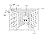
例えば、図2に示すようにフレーム121aにおいて人物122aが建物123aを背景にして立っている写真を撮影する場合を考える。このとき、複数枚撮影するとフレーム121bのように手振れによりフレーム121aに対して構図がずれた画像が撮影されることがある。
【0053】
ズレ検出部114は、画面の周辺に位置する建物123aのうち輝度の高い点である窓124aのエッジ125aをエッジ検出により特徴点として取り出し、この特徴点125aと、フレーム121bにおける特徴点125bと比較し、この差分を補正(座標変換)する。
【0054】
図2では、フレーム121bの特徴点125bを矢印126のようにフレーム121aの特徴点125aに重ねるようにして、フレーム121bを座標変換する。
【0055】
ここで、特徴点として撮影画面の周辺を選択する理由を以下に説明する。
【0056】
多くの撮影の場合では、画面中央近傍に主被写体が位置し、且つ主被写体は人物である場合が多い。このようなとき、主被写体を特徴点として選ぶと被写体振れによる不都合が出てくる。
【0057】
すなわち、複数枚の撮影を行っているときに撮影者の手振ればかりでなく、被写体振れも重畳してくるので被写体振れに基づいて画像の座標変換をしてしまう。
【0058】
この場合、主被写体の構図が適正になるように座標変換するので好ましい画像ができるように思われるが、一般的には人物の動きは複雑であり、特徴点を選ぶ場所によってズレ検出精度が大きく左右される。
【0059】
例えば、主被写体(人物)の眼を特徴点として選んだ場合は瞬きの影響が出るし、手の先を特徴点として選択した場合には手は動きやすいので実際の被写体全体の振れとは異なってしまう。
【0060】
このように人物の1点を特徴点として画像の座標変換を行っても、その人物のすべてが適正に座標変換される訳ではないし、複数の画像を座標変換して合成する場合においても、画像ごとに座標の位置がばらつき、好ましい画像は得られない。
【0061】
そこで、本実施形態のように背景のような静止被写体を特徴点として選択して、画像の座標変換を行ったほうが好ましい画像が得られる。この場合には、上述した被写体振れの影響が出てくる。
【0062】
そこで、本実施形態においては、複数回に分けた撮影コマの1コマだけストロボ16aの光を被写体に照射するようにしている。
【0063】
ここで、ストロボ16aを使用して撮影した画像を第1の画像、ストロボ16aを使用しないで撮影した複数の画像を第2の画像群とする。
【0064】
このとき、第1の画像と第2の画像群の間には、前述した構図ズレ以外にも以下の違いがある。
【0065】
それは、第1の画像において閃光の届いた被写体領域の明るさは、第2の画像群のうち各画像における同じ領域の明るさとは異なるということである。
【0066】
そして、第1の画像において閃光の届いた被写体に対しては十分な露出が得られ、届かない背景は露出が不足することになる。これは、一般的に人物などの主被写体は、カメラの近くに位置しているために閃光が届き、背景はカメラから遠いために閃光が届かないからである。
【0067】
そして、露出の不足している背景に対しては、第2の画像群について構図ズレを修正しながら合成することで補う。
【0068】
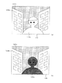
図3は、ズレ検出部114による特徴点の抽出領域の選択方法を示したものである。ストロボ16aを使用した第1の画像127(図3(a))と、ストロボ16aを使用しない第2の画像群(図3(b)に、第2の画像群のうち1つの画像128を示す)とを比較すると、人物122aに関して第1の画像127ではストロボ光が届き、第2の画像128では人物にストロボ光が照射されていないため人物が暗くなっている。
【0069】
これに対して、ストロボ光の届かない背景では、建物123a(123b)の特徴点125a(125b)の明るさの変化は、第1の画像127および第2の画像128間で変化が無い。
【0070】
このように明るさの変化の無い背景領域は、ストロボ光が届かずに露出が不足するので、この領域を画像合成のポイントと考えて、この部分を特徴点の抽出領域にして構図ズレを補正(座標変換)する。
【0071】
図3においては、上記のように第1の画像127と第2の画像128で明るさの変化が無い画面周辺の建物123a(123b)の中において、輝度の高い点である窓のエッジ125aをエッジ検出により特徴点として取り出す。
【0072】
そして、図2で説明したのと同様に第1の画像127における特徴点125aと、第2の画像128における特徴点125bと比較し、その差分を補正(座標変換)する。すなわち、座標変換部(座標変換手段)115は、第2の画像128の特徴点125bを第1の画像127の特徴点125aに重ねるように第2の画像128を座標変換する。
【0073】
そして、第2の画像群の中で2枚目以降の画像についても各々特徴点125bの座標を求め、その座標が第1の画像127で定めた特徴点125aの座標と重なるように座標変換部115は各画像(第2の画像群)を座標変換してゆく。
【0074】
ここでは、説明のために画像ごとの特徴点座標を求めているが、実際には第1の画像127と第2の画像群のうち1枚目の画像128を相関演算し、各々対応する画素の変化をズレ検出部114が動きベクトルとして求め、特徴点の変化としている。
【0075】
そして、第2の画像群の2枚目に対しても第1の画像127との相関演算で特徴点の変化を求め、以下同様にして各画像の特徴点の変化を求めてゆく。
【0076】
なお、特徴点は1箇所だけ選択するのではなく、複数のポイントを選択しておき、これらのポイントの動きベクトルの平均値、又はスカラーの最小値を特徴点の変化としてもよい。
【0077】
ここで、特徴点の変化として上記最小値を利用するのは、画面周辺で選択された特徴点もそれ自身が移動する可能性があるため、もっとも移動しない特徴点を選ぶためである。
【0078】
座標変換部115で座標変換された各画像は、画像合成部(合成手段)116に出力されて各画像が1枚の画像に合成される。
【0079】
以上のように本実施形態ではストロボ16aを用いた第1の画像127を基準(中心)にして、その画像に重なるように第2の画像群128の各画像を座標変換している。
【0080】
ここで、第1の画像127を基準にする理由を説明する。
【0081】
図2のように構図のズレた2枚の写真を合成する場合、図4に示すように2枚の画像が重ならない領域129が生ずる。そこで、画像合成部116は、領域129をカットして、2枚の画像が重なった領域のみについて拡散補完処理を行い、もとのフレームの大きさにする。
【0082】
このため、第2の画像群の各画像は構図ズレの向きや大きさに応じて画面の周辺が削られてしまう。
【0083】
第1の画像127と第2の画像群128の中でもっとも画像情報が良好なのは、ストロボ16aを使用した第1の画像127である。
【0084】
そこで、第1の画像127の周辺を削らないようにするために、第1の画像127を基準にしてその基準に対して第2の画像群128の各画像を重ねてゆくのが好ましい。
【0085】
デジタル画像の場合には、1枚の露出不足の写真でもゲインアップすることで露出の補正が可能であるが、ゲインを高くするとノイズも多くなり見苦しい画像になってしまう。
【0086】
しかし、本実施形態のように多くの画像を合成することで画像全体のゲインをアップさせる場合には、各画像のノイズが平均化されるためにS/N比の大きい画像を得ることができ、結果的にノイズを抑えて露出を適正化することができる。
【0087】
別の考え方をすれば、例えばノイズを許容して撮像部19を高感度にして複数枚撮影し、これらを加算平均することで画像に含まれるランダムノイズを減少させているとも云える。
【0088】
合成された画像データは、画像補正部117に入力されてガンマ補正や圧縮処理が行われ、その後表示部118に撮影画像として表示されるとともに記録部119に記録される。
【0089】
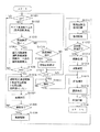
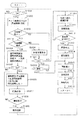
図5は、本実施形態のカメラの撮影動作をまとめたフローチャートであり、このフローはカメラの電源がオンになったときにスタートする。
【0090】
ステップS1001では、撮影者がレリースボタンの半押し操作によりsw1がオンになるまで待機し、sw1がオンになるとステップS1002に進む。
【0091】
ステップS1002では、撮像部19において撮像が行われる。撮影制御部18は、信号処理部111からの出力に基づいて画像のコントラストを検出しながら、AF駆動モータ14aを駆動して撮影レンズ11を光軸方向に移動させる。
【0092】
そして、もっともコントラストが高かった時点で撮影レンズ11の駆動を停止させることにより撮影光学系を合焦状態とする(山登り方式によるAF)。なお、位相差検出により焦点調節を行うこともできる。
【0093】
また、撮影制御部18は、同時に撮像部19の出力に基づいて被写体の明るさを求める。
【0094】
ステップS1003では、撮影者が防振操作部120をオンにしているか否かを判別し、オンにしているときはステップS1004に進み、オフの時はステップS1019に進む。
【0095】
先ず始めに防振操作部120をオンにしている場合に流れるフローについて説明する。
【0096】
ステップS1004では、ステップS1002で求めた被写体の明るさ等の撮影条件から撮影する枚数と各々の露光時間を求める。
【0097】
ここで云う撮影条件とは、
・被写体の明るさ
・撮影光学系の焦点距離
・撮影光学系の明るさ(絞りの値)
・撮像部19の感度
の4点である。
【0098】
例えば、撮像部19の感度がISO200に設定されていたとする。
【0099】
被写体の明るさを測定(測光)し、この測光結果に基づいて適正に露光するためには、絞り13aを全開(例えばf2.8)にするとともにシャッタ12aの閉じタイミング、すなわち露光時間を1/8秒にする必要があるとする。
【0100】
ここで、撮影光学系の焦点距離が35mmフィルム換算で30mmであるとき、露光時間を1/8秒とする撮影では手振れにより像振れが発生する恐れがあるので、像振れが生じないように露光時間を1/32秒に設定して4回撮影を行うように設定する。
【0101】
一方、撮影焦点距離が300mmであるときには、像振れが生じないように露光時間を1/320秒に設定して40回撮影を行うように設定する。
【0102】
このように複数枚撮影を行う時の露光時間を撮影条件に合わせて決定し、さらに何枚撮影するかも撮影条件に合わせて設定する。
【0103】
同一被写体を複数枚に分けて撮影するとしても、各撮影の露光条件はなるべく適正露光に近い方が撮像部19での撮像において正確な情報が得られる。
【0104】
このため、暗い被写体の場合や、絞り13aが絞り込んでおり暗い場合、撮像部19の感度が低く設定されている場合には、複数撮影といえども各撮影の露光時間はなるべく長くして有効な露光条件にする。
【0105】
但し、あまり露光時間を長くすると、手振れによる画像劣化の影響が像面に表れるため、上述したように撮影光学系の焦点距離が35mmフィルム換算で30mmであるときは像振れが生じないように約焦点距離分の一に等しい露光時間である1/32秒に設定している。
【0106】
そして、その露光時間では足りない分を撮影枚数で補完している。
【0107】
焦点距離が長い場合には、さらに露光時間を短くしないと手ぶれによる像劣化が生ずるのでさらに露光時間を短くして、その分撮影枚数を増やして露出補完を行う。
【0108】
このように複数枚撮影における露光時間は、撮影被写体が暗いほど、また撮影レンズが暗いほど長くなり、撮像部19の感度が低いほど長くなり、レンズの焦点距離が長いほど短くなる。
【0109】
そして、複数枚撮影における撮影枚数は、撮影被写体が暗いほど、また撮影レンズが暗いほど多くなり、撮像部19の感度が低いほど多くなり、レンズの焦点距離が長いほど多くなる。
【0110】
以上のように撮影条件に応じた露光時間および撮影枚数の演算が終了した後で、カメラのファインダ内に設けられた表示部やカメラの外装に設けられた液晶表示部に、防振モード(複数回撮影モード)が設定されたことを表示すると同時に、求めた撮影枚数を表示して撮影者に知らせる。
【0111】
ステップS1005では、レリースボタンの全押し操作によりsw2がオンになるまでステップS1001からステップS1005を循環して待機する。
【0112】
ステップS1006では、1枚目の撮影を開始する。
【0113】
また、この時同時に撮影開始の発音を、発音駆動部(発音手段)17bを介してスピーカー(発音手段)17aを駆動することにより行う。
【0114】
この音は例えば、「ピッ」と云う電子音でもよいし、フィルムカメラなどにおけるシャッタの開き音、ミラーアップの音でもよい。
【0115】
ステップS1006から後述するステップS1014までは短い露光時間の撮影を複数回繰り返し、複数の撮影により得られた画像を合成してみかけの露出を適正にする合成撮影モードの動作である。
【0116】
ここで、このステップに記載されているように始めの1枚目の撮影は、上述した第1の画像127(図3a)を得るためにストロボ16aを発光させて撮影する。
【0117】
ステップS1007では、撮影した画像を一旦画像記憶部113に記憶しておく。
【0118】
ステップS1008では、すべての撮影が完了するまでステップS1006、♯1007を循環して待機する。このとき、2枚目以降の撮影は第2の画像群を得るためにストロボ16aを使用しないで撮影する。
【0119】
そして、撮影が完了するとステップS1009に進む。
【0120】
ステップS1009では、撮影完了の発音を、発音駆動部17bを介してスピーカー17aを駆動することにより行う。
【0121】
この音は、例えば「ピッピッ」と云う電子音でもよいし、フィルムカメラなどにおけるシャッタの閉じ音、ミラーダウン音やフィルム巻き上げ音でもよい。
【0122】
このように複数枚撮影する場合において、その動作を表す発音は1セット(最初の撮影の露光開始と最後の撮影の露光完了とで1回)なので撮影者に複数枚撮影の違和感を与えることはない。
【0123】
すなわち、通常の撮影(1回の露光)を行う場合と複数枚撮影を行う場合とで、発音の回数が等しくなっており、撮影者に撮影時の違和感を与えるのを防止することができる。
【0124】
ステップS1010では、ズレ検出部114が画像の周辺領域(例えば図3の建物123a、123b)の中から特徴的な像(特徴点)を抽出し、その像の座標を求める。
【0125】
これは前述したように第1の画像127と第2の画像群の各画像128とをそれぞれ比較して明るさの異なる領域(即ちストロボ16aの閃光が十分被写体を照射した領域)以外の領域(即ちストロボ16aの閃光が被写体を十分照射していない領域)から特徴点を抽出しその座標を求めることである。
【0126】
ステップS1011では、座標変換部115が各画像の座標変換を行う。ここで、最初の1枚の画像(ストロボ16aを用いた第1の画像127)のみ座標の変換は行わない。すなわち、この第1の画像127を座標変換の際の基準とする。
【0127】
ステップS1012では、第2の画像128のうちすべての画像について座標変換が終了するまでステップS1010、1011を循環して待機し、すべての画像の座標変換が完了するとステップS1013に進む。
【0128】
ステップS1013では、第1の画像127と座標変換された第2の画像群の各画像128との合成を行う。
【0129】
ここで、画像の合成は各画像の対応する座標の信号を加算平均することで行い、画像内のランダムノイズは加算平均することで減少させられる。そして、ノイズの減少した画像をゲインアップして露出の適正化を図る。
【0130】
ステップS1014では、合成された画像のうち各画像が構図ブレにより重ならなかった領域(図4の領域129)をカットし、元のフレームの大きさになるように画像を拡散補完する。
【0131】
ステップS1015では、合成画像信号に対してガンマ補正や圧縮処理を行う。
【0132】
ステップS1016では、ステップS1015で得られた画像を、カメラの背面などに配置された液晶表示部(表示部118)に表示する。
【0133】
ステップS1017では、ステップS1015で得られた画像データを、例えば半導体メモリなどで構成され、カメラに対して着脱可能な記録媒体(記録部119)に記録する。
【0134】
ステップS1018では、スタートに戻る。
【0135】
なお、ステップS1018の段階でまだ継続してレリースボタンが半押し操作されsw1がオンになっているときは、そのままステップS1001、♯1002、♯1003、♯1004と再度フローを進めてゆく。
【0136】
また、ステップS1018の段階でレリースボタンが全押し操作されsw2がオンになっているときには、スタートに戻らずステップS1018で待機する。
【0137】
次に、ステップS1003で防振操作部120がオフの場合のときに流れるフローについて説明する。
【0138】
ステップS1003において、防振操作部120がオフと判断されたときには、ステップS1019に進む。
【0139】
ステップS1019では、防振システムを使用しないと手振れによる画像劣化が生ずる撮影条件であるか否かを判断する。
【0140】
撮影条件は前述したように被写体の明るさ、レンズの明るさ、撮像感度、撮影焦点距離であり、被写体の明るさ、レンズの明るさ、撮像感度に基づいて露光時間を求め、その露光時間が現状の撮影焦点距離においては手振れによる画像劣化の可能性があるか否かをステップS1019で判断している。
【0141】
そして、画像劣化の可能性がある時にはステップS1020に進み、そうでない時はステップS1021に進む。
【0142】
ステップS1020では、カメラのファインダ内に設けられた表示部やカメラの外装に設けられた液晶表示部(表示部118)に、防振モードに設定することを推奨する表示を行う。
【0143】
ステップS1021では、レリースボタンが全押し操作され、sw2がオンになるまでステップS1001からステップS1021を循環して待機する。
【0144】
ステップS1022では、通常の撮影(一回の露光で有効な露光条件を形成する通常撮影モード、第2の撮影モード)が完了する迄待機し、露光完了と共にステップS1015に進む。
【0145】
ここでは省いているが、通常撮影モードでの撮影においても撮影開始から完了の動作に合わせて撮影動作音をスピーカー17aより発音している。
【0146】
すなわち、合成撮影モード(複数枚の撮影の合成、第1の撮影モード)においても、通常撮影モードにおいても同じ様式の撮影動作音を発音している。この場合には、スピーカー17aの動作音の長さ(撮影開始音から撮影完了音迄の長さ)の違いにより長秒時露光か否かを撮影者が認識できる程度であり、複数枚の撮影を行っているか否かは撮影者には分からないようになっている。
【0147】
このため、合成撮影モードにおいても特別な撮影を行っているという認識を撮影者に与えることがなく、使いやすいカメラになっている。
【0148】
ステップS1015では、合成画像信号に対してガンマ補正や圧縮処理を行う。
【0149】
ステップS1016では、ステップS1015で得られた画像を、カメラ背面などに配置された液晶表示部(表示部118)に表示する。
【0150】
ステップS1017では、ステップS1015で得られた画像データを、例えば半導体メモリなどで構成され、カメラに対して着脱可能な記録媒体(記録部119)に記録する。
【0151】
ステップS1018では、スタートに戻る。
【0152】
このフローで分かるように防振操作部120をオフにしている場合においても手振れによる画像劣化が生ずる撮影条件の時には、撮影者に防振システムの活用(合成撮影モード)を促す表示を行って画像劣化を未然に防ぐようにしている。
【0153】
そして、合成撮影モードにおいても各々の露光時間は、撮影光学系の焦点距離に応じて変更することでいかなる焦点距離においても望ましい撮影ができる。
【0154】
(第2実施形態)
本実施形態は、第1実施形態の変形例である。本実施形態のカメラの構成は、第1実施形態(図1)と概ね同様であり、同じ部材については同一符号を付して説明する。
【0155】
第1実施形態においてはズレ検出部114による特徴点の抽出領域は、撮影された各画像の明るさを比較してストロボ16aの閃光照射が不十分な領域を特徴点の抽出領域として設定している。
【0156】
しかし、特徴点の抽出領域は、この例に限られず撮影時の撮影画面内のフォーカスエリア外の領域を特徴点の抽出領域としたり、現在ピントが合っている領域以外の領域を特徴点の抽出領域としたりすることができる。
【0157】
これは撮影するときには主被写体(人物)をフォーカスエリア(焦点検出領域)に重ねるため、特徴点を主被写体以外にするためには、フォーカスエリア以外の領域を特徴点抽出領域に設定すればよいからである。
【0158】
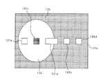
図6は、撮影画面内における特徴点抽出領域を示した図であり、撮影画面(フレーム121a内)に設けられたフォーカスエリア131a、131b、131c、131d、131eの中で主被写体を捕らえているフォーカスエリア130cで合焦している場合には、このフォーカスエリア130cを中心とする主被写体領域132を除く画面周辺領域130を特徴点抽出領域に設定する。
【0159】
すなわち、主被写体がフォーカスエリア131a、131b、131c、131d、131eのうちいずれかのフォーカスエリアに位置しているかに応じて、主被写体領域132および特徴点抽出領域が変更される。
【0160】
そして、この特徴点抽出領域の中で適した像を特徴点として、この特徴点の座標に基づいて各画像のズレを補正して画像合成を行うようにすれば好ましい画像合成が行える。
【0161】
また、図5のフローのようにすべての画像の座標変換が終了して、これらの画像の保存が終わってから画像の合成を行うのではなく、撮影を続行しながら画像の合成を同時進行で行ってもよい。
【0162】
図7は、このような動作を説明するタイミングチャートである。露光f1(f1はストロボ16aを利用した露光)に対して、撮像部19で光電変換されて電荷蓄積された信号が撮像信号F1として読み出される。同様にして露光f2(f2はストロボ16aを利用しない)に対して、撮像部19で光電変換されて電荷蓄積された信号が撮像信号F2として読み出される。撮像信号F2の読み出しと同時進行で前の撮像信号F1と今回の撮像信号F2の相関演算を行う。これにより、2つの画像における特徴点の変化を求め、2つの撮像信号F1、F2を合成して合成信号C2を得る。
【0163】
次に、撮像信号F3の読み出しと同時進行で前回の合成信号C2と今回の撮像信号F3の相関演算を行うことで特徴点の変化を求め、合成信号C2および撮像信号F3を合成して合成信号C3を得る。
【0164】
次に、撮像信号F4の読み出しと同時進行で前回の合成信号C3と今回の撮像信号F4の相関演算を行うことで特徴点の変化を求め、合成信号C3および撮像信号F4を合成して合成信号C4を得る。
【0165】
そして、得られた合成信号C4(合成画像)を、カメラ背面などに設けられた液晶表示部に表示するとともに、記録媒体に記録する。
【0166】
図8は、以上の動作を説明するフローチャートである。図5のフローチャートと比較すると、ステップS1007の画像保存がなくなり、ステップS1012とステップS1013の順序が逆になっている。
【0167】
ステップS1007の画像保存が廃止されたのは、本実施形態では各撮影画像は撮影と同時進行で前の撮影画像と合成されるため、画像合成ステップS1013に1枚だけ合成画像が保管されていれば良く、他の撮影画像は不要であるためである。
【0168】
すなわち、撮影ごとに合成画像が更新されるので各撮影画像を保存しておく必要がない。そのため、本実施形態のカメラでは、図1で示した画像記憶部113を備えていない。
【0169】
なお、図8のフローにおいてもステップS1012の全画像処理が完了するまで次の撮影を行わないように見えるが、実際は図7のタイミングチャートのように撮影や撮像信号出力、相関演算や画像合成は同時進行で行われている。
【0170】
(第3実施形態)
第1実施形態においては、防振システムの必要な撮影条件の場合にはその旨を表示して撮影者に知らせることにより、撮影の失敗を未然に防いでいる。
【0171】
しかし、この実施形態における防振システムは、複数枚の画像を合成して適性露出を得る性格上、露光時間が長くなる。
【0172】
上述したように1/8秒の露光時間で焦点距離30mmでは、1/32秒の露光時間の撮影を4回に分けて行い、それらを合成して適性露出を得ている。
【0173】
しかし、それらの撮影間の処理時間(例えば画像データの転送時間、データ保存時間)も必要なことから、実際に1/32秒の露光時間の撮影が4回終了するまでには1/8秒以上の時間(例えば1/4)が必要になる。
【0174】
このような長秒時にわたる撮影(被写体が暗いときの撮影)で問題になる被写体振れは、上述したようにストロボ16aを用いることで解決できるが、被写体がある程度明るい場合にはストロボ16aが閃光しない撮影コマ(第2の画像群)においても被写体が写りこみ、合成後の画像ではストロボ16aによる被写体ブレ抑制作用は薄れてくる。
【0175】
すなわち、ある程度明るい撮影条件において合成撮影モードを用いると通常撮影モードよりかえって被写体振れが目立つ場合も出てくる。
【0176】
振動ジャイロや補正光学装置を用いた光学防振システムにおいては、これらの要素をカメラに搭載しなくてはならないこと(カメラの大型化)や、手振れのシフト成分や光軸回りのロール成分は補正できないデメリットがある。しかし、光学防振システムが不要の撮影条件において、画像合成による防振システムにより得られた画像が防振オフの画像より像振れが目立つことはない。
【0177】
一方、画像合成による防振システムにおいてはカメラに特別な要素を搭載する必要がないこと、手振れのシフト成分や光軸回りのロール成分も補正できるメリットがある。
【0178】
一方、画像合成による防振システムを不要とする撮影条件において、防振システムをオンにして得られた画像が防振システムをオフにして得られた画像よりも被写体振れが目立つ可能性がある。
【0179】
そこで、本実施形態においては、画像合成による防振システム不要の撮影条件においては、防振システムをオンにした撮影は許可しない(画像合成による防振システムが必要な撮影条件の時に、この防振システムによる撮影を許可する)ようにしている。
【0180】
最近のデジタルカメラは、撮像部19の感度を高めてもノイズが出にくくなっており、また、発生したノイズの処理も上手になってきている。
【0181】
このため、ある程度被写体が暗くなるまで(或いは焦点距離が長くなるまで、撮影光学系が絞りこまれるまで)は、撮像部19の感度を上げることで露光時間を長くしないでも適正露光が得られるようにし、露光時間を長くしなければ露出不足になる場合にのみ画像合成による防振システムを使用するようにしている。
【0182】
具体的には、撮影者が防振操作部120をオンにして撮影しようとしても被写体が明るい場合等では防振不要が表示されると共に通常撮影モードにて撮影が実行される。
【0183】
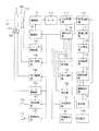
図9は、本実施形態のフローチャートであり、図5のフローチャートと異なる点は、防振操作部120がオンになっている場合でも防振撮影条件か否かを判定している点と、防振撮影条件でない場合には防振操作部120がオンになっていても通常撮影モードで撮影を実行する点(この時防振不要表示を行うこと)である。なお、本実施形態のカメラの構成は、第1実施形態のカメラの構成(図1)と同様である。
【0184】
図9は、本実施形態におけるカメラの撮影動作をまとめたフローチャートであり、このフローはカメラの電源がオンになったときにスタートする。
【0185】
ステップS1001では、撮影者がレリースボタンを半押し操作することによりsw1がオンになるまで待機し、sw1がオンになるとステップS1002に進む。
【0186】
ステップS1002では、撮像部19において被写体を撮像する。撮影制御部18は、信号処理部111からの出力に基づいて画像のコントラストを検出しながら、AF駆動モータ14aを駆動して撮影レンズ11を光軸10方向に移動させる。
【0187】
そして、もっともコントラストが高かった時点で撮影レンズ11の駆動を停止させることにより撮影光学系を合焦状態とする。
【0188】
また、撮影制御部18は、同時に撮像部19の出力に基づいて被写体の明るさを求める。
【0189】
ステップS1003では、撮影者が防振操作部120をオンにしているか否かを判別し、オンにしているときはステップS1019に進み、オフの時はステップS1021に進む。
【0190】
先ず始めに防振操作部120をオンにしている場合を説明する。
【0191】
ステップS1019では、防振システム(合成撮影モード)を使用しないと手振れによる画像劣化が生ずる撮影条件であるか否かを判断している。
【0192】
撮影条件は、前述したように被写体の明るさ、レンズの明るさ、撮像感度、撮影焦点距離であり、被写体の明るさ、レンズの明るさ、撮像感度に基づいて露光時間を求め、その露光時間が現状の撮影焦点距離においては手振れによる画像劣化の可能性があるか否かをステップS1019で判断している。
【0193】
ここで、撮像感度は撮像部19の感度状態であり、デジタルカメラの場合には撮像部19の感度は撮影条件によって自動的に変更されるオートモードと、撮影者の好みで撮像感度を固定設定する感度固定モードがある。
【0194】
オートモードの場合には、被写体の明るさ、レンズの明るさに応じて露光時間を設定し、現在設定されている撮影焦点距離に対して求めた露光時間では像振れが生じないか否かを判定する。
【0195】
そして、像振れが生ずる可能性がある場合には撮像感度を上げることで露光時間を短くし、それでも像振れが発生しそうな露光時間の場合には防振(合成撮影モードでの撮影)が必要であると判断する。
【0196】
また、感度固定モードの場合には、被写体の明るさ、レンズの明るさ、設定されている撮像感度に応じて露光時間を設定し、現在設定されている撮影光学系の焦点距離に対して求めた露光時間において像振れが生じないか否かを判定する。ここで、像振れが生ずる可能性がある場合には、防振が必要であると判断する。
【0197】
上記オートモードおよび感度固定モードの中間として、撮像感度の変更をある程度の幅まで許容する半オートモードなども撮影シーン選択モード(例えばポートレートモード)では考えられる。
【0198】
この様な場合においても許容される撮像感度での露光時間において像振れが生ずる可能性がある場合には、防振が必要であると判断する。
【0199】
そして、防振が必要と判断される場合にはステップS1004に進み、不要の時はステップS2001に進む。
【0200】
まず、防振が必要と判断されて、ステップS1004に進むフローについて説明する。
【0201】
ステップS1004では、ステップS1019で求めた通常撮影時の撮影条件から撮影する枚数と各々の露光時間を求める。
【0202】
ここで云う撮影条件とは
・被写体の明るさ
・撮影光学系の焦点距離
・撮影光学系の明るさ(絞りの値)
・撮像部19の感度
の4点である。
【0203】
例えば、ステップS1019で露光時間が1/8秒必要であるとする。
【0204】
このとき撮影光学系の焦点距離が35mmフィルム換算で30mmであるとき、露光時間を1/8秒とする撮影では手振れによる像振れが生じる恐れがあるので像振れが生じないように露光時間を1/32秒に設定して4回撮影を行うように設定する。
【0205】
また、撮影焦点距離が300mmであるときには像振れが生じないように露光時間を1/320秒に設定して40回撮影を行うように設定する。
【0206】
このように複数枚撮影を行う時の露光時間を撮影条件に合わせて決定し、さらに何枚撮影するかも撮影条件に合わせて設定する。
【0207】
同一被写体を複数枚に分けて撮影するとしても、各撮影の露光条件はなるべく適正露光に近い方が撮像部19での撮像において正確な情報が得られる。
【0208】
このため、暗い被写体の場合や、絞り13aが絞り込んでおり暗い場合、撮像部19の感度が低く設定されている場合には、複数撮影といえども各撮影の露光時間はなるべく長くして有効な露光条件にする。
【0209】
但し、あまり露光時間を長くすると、手振れによる像劣化の影響が像面に表れるため、上述したように撮影焦点距離が35mmフィルム換算で30mmであるとき、像振れの恐れのない約焦点距離分の一に等しい露光時間である1/32秒に設定している。
【0210】
そして、その露光時間では足りない分を撮影枚数で補完している。
【0211】
焦点距離が長い場合には、さらに露光時間を短くしないと手振れによる像劣化が生ずるのでさらに露光時間を短くして、その分撮影枚数を増やして露出補完を行う。
【0212】
このように複数枚撮影における露光時間は、撮影被写体が暗いほど、また撮影レンズが暗いほど長くなり、感度固定モードでは撮像部19の感度が低いほど長くなり、レンズの焦点距離が長いほど短くなる。
【0213】
そして、複数枚撮影における撮影枚数は、撮影被写体が暗いほど、また撮影
レンズが暗いほど多くなり、感度固定モードでは撮像部19の感度が低いほど多くなり、レンズの焦点距離が長いほど多くなる。
【0214】
以上のように撮影条件に応じた露光時間および撮影枚数の演算が終了した後で、カメラのファインダ内に設けられた表示部やカメラの外装に設けられた液晶表示部に、防振モード(複数回撮影モード)が設定されたことを表示すると同時に、求めた撮影枚数を表示して撮影者に知らせる。
【0215】
ステップS1005では、レリースボタンの全押し操作によりsw2がオンになるまでステップS1001からステップS1005を循環して待機する。
【0216】
ステップS1006では、1枚目の撮影を開始する。
【0217】
また、この時同時に撮影開始の発音を、発音駆動部17bを介してスピーカー17aを駆動することにより行う。
【0218】
この撮影動作音は、例えば「ピッ」と云う電子音でもよいし、フィルムカメラなどにおけるシャッタの開き音、ミラーアップの音でもよい。
【0219】
なお、ステップS1006から後述するステップS1014までは短い露光時間の撮影を複数回繰り返し、複数の撮影により得られた画像を合成してみかけの露出を適正にする合成撮影モードの動作である。
【0220】
ここで、このステップに記載されているように始めの1枚目の撮影は前述の第1の画像127を得るためにストロボ16aを閃光させて撮影する。
【0221】
ステップS1007では、撮影した画像を一旦画像記憶部113に記憶しておく。
【0222】
ステップS1008では、すべての撮影が完了するまでステップS1006、♯1007を循環して待機する。
【0223】
このとき2枚目以降の撮影は第2の画像群を得るためにストロボ16aを使用しないで撮影する。
【0224】
そして、撮影が完了するとステップS1009に進む。
【0225】
ステップS1009では、撮影完了の発音を、発音駆動部17bを介してスピーカー17aを駆動することにより行う。
【0226】
この撮影動作音は、例えば「ピッピッ」と云う電子音でもよいし、フィルムカメラなどにおけるシャッタの閉じ音、ミラーダウン音やフィルム巻き上げ音でもよい。
【0227】
このように複数枚撮影する場合においてもその動作を表す発音は1セット(最初の撮影の露光開始と最後の撮影の露光完了とで1回)なので、上述したように撮影者に複数枚撮影の違和感を与えることはない。
【0228】
ステップS1010では、ズレ検出部114が画像の周辺領域(例えば図3の建物123a、123b)の中から特徴的な像(特徴点)を抽出し、その像の座標を求める。
【0229】
これは前述したように第1の画像127と第2の画像群の各画像128とをそれぞれ比較して明るさの異なる領域(即ちストロボ16aの閃光が十分被写体を照射した領域)以外の領域(即ちストロボ16aの閃光が被写体を十分照射していない領域)から特徴点を抽出しその座標を求めることである。
【0230】
ステップS1011では、座標変換部115が各画像の座標変換を行うが、最初の1枚目の画像(ストロボ16aを用いた第1の画像127)のみ座標の変換は行わない。すなわち、第1の画像127を座標変換の基準とする。
【0231】
ステップS1012では、すべての画像が座標変換終了するまでステップS1010、1011を循環して待機し、すべての画像の座標変換が完了するとステップS1013に進む。
【0232】
ステップS1013では、画像の合成を行う。
【0233】
ここで、画像の合成は各画像の対応する座標の信号を加算平均することで行い、画像内のランダムノイズは加算平均することで減少させられる。そして、ノイズの減少した画像をゲインアップして露出の適正化を図る。
【0234】
ステップS1014では、合成された画像のうち各画像が構図ブレにより重ならなかった領域(図4の領域129)をカットし、元のフレームの大きさになるように画像を拡散補完する。
【0235】
ステップS1015では、合成画像信号に対してガンマ補正や圧縮処理を行う。
【0236】
ステップS1016では、ステップS1015で得られた画像を、カメラ背面などに配置された液晶表示部(表示部118)に表示する。
【0237】
ステップS1017では、ステップS1015で得られた画像データを、例えば半導体メモリなどで構成され、カメラに対して着脱可能な記録媒体(記録部119)に記録する。
【0238】
ステップS1018では、スタートに戻る。
【0239】
なお、ステップS1018の段階でまだ継続してレリースボタンが半押し操作されてsw1がオンになっているときは、そのままステップS1001、♯1002、♯1003と再度フローを進めてゆく。
【0240】
また、ステップS1018の段階でレリースボタンが全押し操作されてsw2がオンになっているときには、スタートに戻らずステップS1018で待機する。
【0241】
次に、ステップS1003で防振操作部120がオフの場合について説明する。このときステップS1003からステップS1021にフローが流れる。
【0242】
ステップS1021では、レリースボタンが全押し操作されてsw2がオンになるまでステップS1001からステップS1021を循環して待機する。
【0243】
ステップS1022では、通常の撮影(一回の露光で有効な露光条件を形成する通常撮影モード)が完了する迄待機し、露光完了と共にステップS1015に進む。
【0244】
ここでは省いているが、通常撮影モードでの撮影においても撮影開始から完了の動作に合わせて撮影動作音をスピーカー17aより発音している。
【0245】
すなわち、合成撮影モード(複数枚の画像の合成)においても、通常撮影モードにおいても同じ様式の撮影動作音を発音しており、その動作音の長さ(撮影開始音から撮影完了音迄の長さ)の違いにより長秒時露光か否かを撮影者が認識できる程度であり、複数枚の撮影を行っているか否かは撮影者には分からないようになっている。
【0246】
このため、上述したように合成撮影モードにおいても特別な撮影を行っているという認識を撮影者に与えることがなく、撮影者に違和感を与えることなく使いやすいカメラになっている。
【0247】
ステップS1015では、合成画像信号に対してガンマ補正や圧縮処理を行う。
【0248】
ステップS1016では、ステップS1015で得られた画像をカメラ背面などに配置された液晶表示部(表示部118)に表示する。
【0249】
ステップS1017では、ステップS1015で得られた画像データを、例えば半導体メモリなどで構成され、カメラに対して着脱可能な記録媒体(記録部119)に記録する。
ステップS1018では、スタートに戻る。
【0250】
次に、ステップS1019で防振不要と判断されて、ステップS2001に流れるフローについて説明する。
【0251】
ステップS2001では、カメラのファインダ内に設けられた表示部やカメラ背面の表示部118に防振(合成撮影モードでの撮影)が不要であることを表示する。
【0252】
そして、ステップS2001からステップS1021に進む。
【0253】
ステップS1021では、レリースボタンが全押し操作されてsw2がオンになるまでステップS1001からステップS1021を循環して待機する。
【0254】
ステップS1022では、通常の撮影(一回の露光で有効な露光条件を形成する通常撮影モード)が完了する迄待機し、露光完了と共にステップS1015に進む。
【0255】
ここでは省いているが、通常撮影モードでの撮影においても撮影開始から完了の動作に合わせて撮影動作音をスピーカー17aより発音している。
【0256】
すなわち、合成撮影モード(複数枚の画像の合成)においても、通常撮影モードにおいても同じ様式の撮影動作音を発音している。
【0257】
この場合、動作音の間隔(撮影開始音から撮影完了音迄の長さ)の違いにより長秒時露光か否かを撮影者が認識できる程度であり、複数枚の撮影を行っているか否かは撮影者には分からないようになっている。
【0258】
このため、上述したように合成撮影モードにおいても特別な撮影を行っているという認識を撮影者に与えることがなく、使いやすいカメラになっている。
【0259】
ステップS1015では、合成画像信号に対してガンマ補正や圧縮処理を行う。
【0260】
ステップS1016では、ステップS1015で得られた画像を、カメラ背面などに配置された液晶表示部(表示部118)に表示する。
【0261】
ステップS1017では、ステップS1015で得られた画像を、例えば半導体メモリなどで構成され、カメラに対して着脱可能な記録媒体(記録部119)に記録する。
ステップS1018ではスタートに戻る。
【0262】
このフローで分かるように防振操作部120を操作して防振システムをオンにしても撮影条件によっては、防振システムを作動させない(合成撮影モードでの撮影を行わない)ようにすると共に、その表示を行うことで、ある撮影条件下における画像の劣化を未然に防いでいる。
【0263】
(第4実施形態)
図10は、本発明の第4実施形態であるカメラのブロック図であり、図1との違いは防振操作部120が廃止されている点である。なお、図1で説明した部材と同じ部材については同一符号を付して説明を省略する。
【0264】
本実施形態では、防振が必要な撮影条件(防振撮影条件)になったときには自動的に合成撮影モードに移行し、防振撮影条件ではないときには通常撮影モードに固定されるようになっている。
【0265】
このため、撮影者は撮影シーンにあわせて防振の必要性を考えなくてもよく、安定して良好な画像を撮影できる。
【0266】
図11は、本実施形態におけるカメラの撮影動作をまとめたフローチャートであり、このフローはカメラの電源がオンになったときにスタートする。
【0267】
ステップS1001では、撮影者がレリースボタンの半押し操作(sw1オン)を行い撮影準備動作(焦点調節動作、測光動作)が開始されるようになるまでこのステップを循環して待機し、sw1がオンになるとステップS1002に進む。
【0268】
ステップS1002では、撮像部19において被写体を撮像する。撮影制御部18は、信号処理部111からの出力に基づいて画像のコントラストを検出しながら、AF駆動モータ14aを駆動して撮影レンズ11を光軸方向に移動させる。そして、もっともコントラストが高かった時点で撮影レンズ11の駆動を停止する。これにより、撮影光学系が合焦状態となる。
【0269】
また、撮影制御部18は、同時に撮像部19の出力に基づいて被写体の明るさを求める。
【0270】
ステップS1019では、防振システムを使用(合成撮影モード設定)しないと手振れによる画像劣化が生ずる撮影条件であるか否かを判断している。
【0271】
撮影条件は、前述したように被写体の明るさ、レンズの明るさ、撮像感度、撮影焦点距離であり、被写体の明るさ、レンズの明るさ、撮像感度に基づいて露光時間を求め、その露光時間が現状(撮影時)の撮影焦点距離においては手振れによる画像劣化の可能性があるか否かをステップS1019で判断している。
【0272】
ここで、撮像感度は撮像部19の感度状態であり、デジタルカメラの場合には撮像部19の感度は撮影条件によって自動的に変更されるオートモードと、撮影者の好みで撮像感度を固定設定する感度固定モードがある。
【0273】
オートモードの場合には被写体の明るさ、レンズの明るさに応じて露光時間を設定し、現在設定されている撮影焦点距離に対して求めた露光時間では像振れが生じないか否かを判定する。
【0274】
そして、像振れが生ずる可能性がある場合には、撮像感度を上げることで露光時間を短くし、それでも像振れが発生しそうな露光時間の場合には防振(合成撮影モードでの撮影)が必要であると判断する。
【0275】
また、感度固定モードの場合には、被写体の明るさ、レンズの明るさ、設定されている撮像感度に応じて露光時間を設定し、現在設定されている撮影焦点距離に対して求めた露光時間では像振れが生じないか否かを判定する。
【0276】
そして、像振れが生ずる可能性がある場合には防振が必要であると判断する。
【0277】
上記オートモードおよび感度固定モードの中間として、撮像感度の変更をある程度の幅まで許容する半オートモードなども撮影シーン選択モード(例えばポートレートモード)では考えられる。
【0278】
この様な場合においても許容される撮像感度での露光時間において像振れが生ずる可能性がある場合には、防振が必要であると判断する。
【0279】
そして、防振が必要と判断される場合にはステップS1004に進み、不要の時はステップS1021に進む。
【0280】
まず、防振が必要と判断されてステップS1004に進むフローについて説明する。
【0281】
ステップS1004では、ステップS1019で求めた通常撮影時の撮影条件から撮影する枚数と各々の露光時間を求める。
【0282】
ここで云う撮影条件とは
・被写体の明るさ
・撮影光学系の焦点距離
・撮影光学系の明るさ(絞りの値)
・撮像部19の感度
の4点である。
【0283】
例えば、ステップS1019で露光時間を1/8秒にする必要があるとする。
【0284】
ここで、撮影焦点距離が35mmフィルム換算で30mmであるとき、露光時間を1/8秒とした撮影では手振れによる像劣化の恐れがあるので、像劣化が生じないように露光時間を1/32秒に設定して4回撮影を行うように設定する。
【0285】
また、撮影焦点距離が300mmであるときには、手振れによる像劣化が生じないように露光時間を1/320秒に設定して40回撮影を行うように設定する。
【0286】
このように複数枚撮影を行う時の露光時間を撮影条件に合わせて決定し、さらに何枚撮影するかも撮影条件に合わせて設定する。
【0287】
同一被写体を複数枚に分けて撮影するとしても、各撮影の露光条件はなるべく適正露光に近い方が撮像部19での撮像により被写体の正確な情報が得られる。
【0288】
このため、暗い被写体の場合や、絞り13aが絞り込んでおり暗い場合、撮像部19の感度が低く設定されている場合には、複数撮影といえども各撮影の露光時間はなるべく長くして有効な露光条件にする。
【0289】
但し、あまり露光時間を長くすると手振れによる像劣化の影響が像面に表れるため、上述したように撮影焦点距離が35mmフィルム換算で30mmであるときは像振れの恐れのない約焦点距離分の一に等しい露光時間である1/32秒に設定している。
【0290】
そして、その露光時間では足りない分を撮影枚数で補完している。
【0291】
焦点距離が長い場合には、さらに露光時間を短くしないと手振れによる像劣化が生ずるのでさらに露光時間を短くして、その分撮影枚数を増やして露出補完を行う。
【0292】
このように複数枚撮影における露光時間は、撮影被写体が暗いほど、また撮影レンズが暗いほど長くなり、感度固定モードでは撮像素子の感度が低いほど長くなり、レンズの焦点距離が長いほど短くなる。
【0293】
そして、複数枚撮影における撮影枚数は、撮影被写体が暗いほど、また撮影レンズが暗いほど多くなり、感度固定モードでは撮像部19の感度が低いほど多くなり、レンズの焦点距離が長いほど多くなる。
【0294】
以上のように撮影条件に応じた露光時間および撮影枚数の演算が終了した後で、カメラのファインダ内に設けられた表示部やカメラの外装に設けられた液晶表示部に、防振モード(合成撮影モード)が設定されたことを表示すると同時に求めた撮影枚数を表示して撮影者に知らせる。
【0295】
ステップS1005では、レリースボタンの全押し操作により撮影開始の指示があるまでステップS1001からステップS1005を循環して待機する。
【0296】
ステップS1006では、1枚目の撮影を開始する。また、この時同時に撮影開始の発音を、発音駆動部17bを介してスピーカー17aを駆動することにより行う。
【0297】
この撮影動作音は、例えば「ピッ」と云う電子音でもよいし、フィルムカメラなどにおけるシャッタの開き音、ミラーアップの音でもよい。
【0298】
なお、ステップS1006から後述するステップS1014までは、短い露光時間の撮影を複数回繰り返し、複数の撮影によって得られた画像を合成してみかけの露出を適正にする合成撮影モードの動作である。
【0299】
ここで、このステップに記載されているように始めの1枚目の撮影は、前述の第1の画像127を得るためにストロボ16aを閃光させて撮影する。
【0300】
ステップS1007では、撮影した画像を一旦画像記憶部113に記憶しておく。
【0301】
ステップS1008では、すべての撮影が完了するまでステップS1006、♯1007を循環して待機する。このとき、2枚目以降の撮影は第2の画像群を得るためにストロボ16aを使用しないで撮影する。
【0302】
そして、撮影が完了するとステップS1009に進む。
【0303】
ステップS1009では、撮影完了の発音を、発音駆動部17bを介してスピーカー17aを駆動することにより行う。
【0304】
この撮影動作音は、例えば「ピッピッ」と云う電子音でもよいし、フィルムカメラなどにおけるシャッタの閉じ音、ミラーダウン音やフィルム巻き上げ音でもよい。
【0305】
このように複数枚撮影する場合においてもその動作を表す発音は1セット(最初の撮影の露光開始と最後の撮影の露光完了とで1回)なので、上述したように撮影者に複数枚撮影の違和感を与えることはない。
【0306】
ステップS1010では、ズレ検出部114が画像の周辺領域(例えば図3の建物123a、123b)の中から特徴的な像(特徴点)を抽出し、その像の座標を求める。
【0307】
これは前述したように第1の画像127と第2の画像群の各画像128をそれぞれ比較して明るさの異なる領域(即ちストロボ16aの閃光が十分被写体を照射した領域)以外の領域(即ちストロボ16aの閃光が被写体を十分照射していない領域)から特徴点を抽出しその座標を求めることである。
【0308】
ステップS1011では、座標変換部115が各画像の座標変換を行うが、最初の1枚の画像(ストロボ16aを用いた第1の画像127)のみ座標の変換は行わない。すなわち、第1の画像127を座標変換の基準とする。
【0309】
ステップS1012では、すべての画像について座標変換が終了するまでステップS1010、1011を循環して待機し、すべての画像の座標変換が完了するとステップS1013に進む。
【0310】
ステップS1013では、画像の合成を行う。
【0311】
ここで、画像の合成は各画像の対応する座標の信号を加算平均することで行い、画像内のランダムノイズは加算平均することで減少させられる。そして、ノイズの減少した画像をゲインアップして露出の適正化を図る。
【0312】
ステップS1014では、合成された画像のうち各画像が構図ブレにより重ならなかった領域(図4の領域129)をカットし、元のフレームの大きさになるように画像を拡散補完する。
【0313】
ステップS1015では、合成画像信号に対してガンマ補正や圧縮処理を行う。
【0314】
ステップS1016では、ステップS1015で得られた画像を、カメラ背面などに配置された液晶表示部(表示部118)に表示する。
【0315】
ステップS1017では、ステップS1015で得られた画像データを、例えば半導体メモリなどで構成され、カメラに対して着脱可能な記録媒体(記録部119)に記録する。
【0316】
ステップS1018では、スタートに戻る。
【0317】
なお、ステップS1018の段階でまだ継続してレリースボタンの半押し(sw1オン)操作が行われているときは、そのままステップS1001、♯1002と再度フローを進めてゆく。
【0318】
また、ステップS1018の段階でレリースボタンの全押し操作(sw2オン)が継続して操作されているときには、スタートに戻らずステップS1018で待機する。
【0319】
次に、ステップS1019で防振不要と判断されてステップS1021に流れるフローについて説明する。
【0320】
ステップS1021では、レリースボタンの全押し操作による撮影開始の指示があるまでステップS1001からステップS1021を循環して待機する。
【0321】
ステップS1022では、通常の撮影(一回の露光で有効な露光条件を形成する通常撮影モード)が完了する迄待機し、露光完了と共にステップS1015に進む。
【0322】
ここでは省いているが、通常撮影モードでの撮影においても撮影開始から完了の動作に合わせて撮影動作音をスピーカー17aより発音している。
【0323】
すなわち、合成撮影モード(複数枚の画像の合成)においても、通常撮影モードにおいても同じ様式の撮影動作音を発音している。
【0324】
この場合、スピーカー17aの動作音の間隔(撮影開始音から撮影完了音迄の長さ)の違いにより長秒時露光か否かを撮影者が認識できる程度であり、複数枚の撮影を行っているか否かは撮影者には分からないようになっている。
【0325】
このため、上述したように合成撮影モードにおいても特別な撮影を行っているという認識を撮影者に与えることがなく、使いやすいカメラになっている。
【0326】
ステップS1015では、合成画像信号に対してガンマ補正や圧縮処理を行う。
【0327】
ステップS1016では、ステップS1015で得られた画像を、カメラ背面などに配置された液晶表示部(表示部118)に表示する。
【0328】
ステップS1017では、ステップS1015で得られた画像データを、例えば半導体メモリなどで構成され、カメラに対して着脱可能な記録媒体(記録部119)に記録する。ステップS1018ではスタートに戻る。
【0329】
このフローで分かるようにユーザーは、防振(合成撮影モード)の設定を行わなくても撮影条件によって自動的に防振システムを作動(合成撮影モード)、非作動(通常撮影モード)させるようにすると共に防振作動時にはその表示を行うことで、1回の静止画撮影毎に安定した画像の劣化のない撮影ができる。
【0330】
(第5実施形態)
図12は、本発明の第5実施形態であるカメラの構成図である。図1又は図10で説明した部材と同じ部材については同一符号を付して説明を省略する。
【0331】
図1との違いは、防振操作部120が廃止された代わりに振動検出部(振動検出手段)31が設けられている点である。
【0332】
振動検出部31は、光学防振システムに用いられる振動ジャイロなどの高精度なセンサを用いることが理想であるが、検出するのは手振れの波形ではなく大きな手振れが生じたか否かであり、検出周波数特性も限定されるので、加速度センサや光学センサ(AFセンサ)等のより安価なセンサでもよい。
【0333】
そして、本実施形態では、撮影条件により撮影前に予め合成撮影モードと通常撮影モードを自動選択することはない。
【0334】
その代わりに通常撮影モードでの撮影において露光中に振動検出部31が検出する手振れが大きくなったときには合成撮影モードに移行するようになっている。
【0335】
すなわち、撮影中に手振れが大きくなると撮影を中断して再度撮影を行い、2回目の撮影中における手振れが大きくなるとその撮影も中断して3回目の撮影に進み、合成画像が適正露出になるまでこの動作を繰り返すようにしている。
【0336】
このため、手振れが少ない限りにおいては長秒時露光であっても通常撮影モードでの撮影が進められるので、合成撮影モードが苦手な被写体振れの影響をより小さく抑えることができる。
【0337】
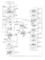
図13は、本実施形態におけるカメラの撮影動作をまとめたフローチャートであり、このフローはカメラの電源がオンになったときにスタートする。
【0338】
ステップS1001では、撮影者がレリースボタンの半押し操作(sw1オン)を行い撮影準備動作(焦点調節動作、測光動作)が開始されるまでこのステップを循環して待機し、sw1がオンされるとステップS1002に進む。
【0339】
ステップS1002では、撮像部19において被写体の撮像を行う。撮影制御部18は、信号処理部111からの出力に基づいて画像のコントラストを検出しながら、AF駆動モータ14aを駆動して撮影レンズ11を光軸方向に移動させる。そして、もっともコントラストが高い時点で撮影レンズ11の駆動を停止する。これにより、撮影光学系は合焦状態となる。
【0340】
また、撮影制御部18は、同時に撮像部19の出力に基づいて被写体の明るさを求め撮影条件を設定する。
【0341】
撮影条件は、前述したように被写体の明るさ、レンズの明るさ、撮像感度、撮影焦点距離であり、被写体の明るさ、レンズの明るさ、撮像感度に基づいて露光時間を求める。
【0342】
ここで、撮像感度は撮像部19の感度状態であり、デジタルカメラの場合には撮像部19の感度は撮影条件によって自動的に変更されるオートモードと撮影者の好みで撮像感度を固定設定する感度固定モードがある。
【0343】
そして、オートモードの場合には、被写体の明るさ、レンズの明るさに応じて露光時間を設定し、絞り13bの値(絞り口径)やシャッタ12aの閉じタイミング(露光時間)を求める。
【0344】
そして、現在設定されている撮影光学系の焦点距離に対して求めた露光時間では手振れによる像振れが生じないか否かを判定し、像振れが生ずる可能性がある場合には撮像感度を上げることで露光時間を短くし、再度絞り13bの値とシャッタ12aの閉じタイミング(露光時間)を演算しなおす。
【0345】
そして、撮影条件にあわせてストロボ16aを自動発光させるモードの場合において、被写体が暗い時にはストロボ16aを発光させるようにし、ユーザーがストロボ16aの強制発光や発光禁止を設定しているときにはそれにあわせてストロボ16aの発光制御を行う。
【0346】
また、感度固定モードの場合には、被写体の明るさ、レンズの明るさ、設定されている撮像感度に応じて露光時間を設定する。
【0347】
上記オートモードおよび感度固定モードの中間として、撮像感度の変更をある程度の幅まで許容する半オートモードなども撮影シーン選択モード(例えばポートレートモード)では考えられる。この様な場合においても上述と同様に設定許容感度範囲内で像振れが少なくなるように撮像感度を上げて露光時間を設定する。
【0348】
ステップS1005では、レリースボタンが全押し操作されることによりsw2がオンになるまでステップS1001からステップS1005を循環して待機する。
【0349】
ステップS3001では、撮影が1枚目か否かを判定し、初めの撮影の場合にはステップS3003に進み、2回目以降の撮影の場合にはステップS3002に進む。
【0350】
1回目の撮影を行う場合には、ステップS3001からステップS3003にフローが流れる。
【0351】
ステップS3003では、露光を開始する。すなわち、今まで撮像部19の各フォトダイオードに蓄積されていた電荷をリセットし再蓄積を開始する。
【0352】
そして、ステップS1002で求めた結果によりストロボ16aを発光する時にはこのステップでストロボ16aを発光する。
【0353】
また、同時に撮影開始の発音を、発音駆動部17bを介してスピーカー17aを駆動することにより行う。この撮影動作音は、例えば「ピッ」と云う電子音でもよいし、フィルムカメラなどにおけるシャッタの開き音、ミラーアップの音でもよい。
【0354】
ステップS3004では、露光時間がステップS1002で設定した時間経過したか否かを判別しており、経過している場合にはステップS1015に進み、そうでないときはステップS3006に進む。
【0355】
ステップS3006では、露光中においてカメラに加わる手振れを振動検出部31により検出しており、その手振れが画像に影響する場合には、ステップS3007に進み、そうでないときはステップS3001、♯3003、♯3004、♯3006を循環して露光を継続する。
【0356】
ここで、手振れが画像に影響するか否かは、その時の手振れ量と撮影焦点距離により求めており、手振れ量が所定量よりも小さくても撮影焦点距離が所定距離よりも長いときには画像が劣化すると判断し、手振れ量が所定量よりも大きくても撮影焦点距離が所定距離よりも短い時には画像は劣化しないと判断する。
【0357】
そして、このステップS3001から♯ステップS3006を循環している間に大きな手振れが生じることなくステップS1002で設定した露光時間に達した場合には前述のようにステップS1015に進む。
【0358】
また、このステップS3001から♯ステップS3006を循環している間に大きな手振れが生じ、画像が劣化すると判断されると、この循環は絶たれてステップS3007に進む。
【0359】
ステップS3007からステップS1014は、上述したように露光中に画像が劣化すると判断された場合に進むステップであり、以降が合成撮影モードとなる。
【0360】
ステップS3007では、シャッタ12aを閉じて露光を中断する。これにより手振れによる画像劣化を防ぐことができる。
【0361】
このとき、設定された適正露光時間は経過していないため、撮影で得られた画像は露出が不足している。
【0362】
ステップS1010では、ズレ検出部114が画像の周辺領域(例えば図3の建物123a、123b)の中から特徴的な像(特徴点)を抽出し、その像の座標を求める。
【0363】
これは前述したように第1の画像127と第2の画像群の各画像128をそれぞれ比較して明るさの異なる領域(即ちストロボ16aの閃光が十分被写体を照射した領域)以外の領域(即ちストロボ16aの閃光が被写体を十分照射していない領域)から特徴点を抽出しその座標を求めることである。
【0364】
しかし、一枚目の画像は比較する画像が無いので座標変換値はゼロである。すなわち、ステップS1011では座標変換部115が各画像の座標変換を行うが、最初の1枚目の画像(ストロボ16aを用いた第1の画像127)のみ座標の変換は行わない。この第1の画像127は、座標変換の基準となる。
【0365】
ステップS1013では、画像の合成を行う。
【0366】
ここで、画像の合成は各画像の対応する座標の信号を加算平均することで行い、画像内のランダムノイズは加算平均することで減少させられる。そして、ノイズの減少した画像をゲインアップして露出の適正化を図る。なお、初めての撮影画像の場合には合成する画像がないので合成は行わない。
【0367】
ステップS3008では、合成された撮影画像の合計露光時間がステップS1002で設定された露光時間(設定露光時間)に達したか否かを判定しており、設定露光時間に達して適正露光と判断した場合にはステップS1009に進み、まだ露出が不足しているときにはステップS3001に戻り次の合成用の画像を撮影する。
【0368】
以下、先ずステップS3008で露出が不足しており、合成撮影のためにステップS3001に戻った場合を説明する。
【0369】
ステップS3001に戻った場合、撮影は2回目なのでフローはステップS3002に進む。
【0370】
ステップS3002では、露光を開始する。初めに今まで撮像部19の各フォトダイオードに蓄積されていた電荷をリセットし再蓄積を開始する。
【0371】
ステップS3003でストロボ16aを発光しており、撮影動作音(露光開始のための音)も鳴らしているので、このステップではストロボ16aの発光も、発音も行わない。
【0372】
ステップS3005では、ステップS1002で設定した露光時間に対してステップS3003の撮影での露光時間の残りの時間(露出不足分を補完する時間)が経過したか否かを判別する。そして、残り時間が経過している場合にはステップS3007に進み、そうでないときはステップS3006に進む。
【0373】
ステップS3006では、露光中にカメラに加わる手振れを振動検出部31により検出しており、その手振れが画像に影響する場合にはステップS3007に進みそうでないときはステップS3001、♯3002、♯3005、♯3006を循環して露光を継続する。
【0374】
ここで、手振れが画像に影響するか否かはその時の手振れ量と撮影焦点距離により求めており、上述したように手振れが小さくても撮影焦点距離が長いときには画像が劣化すると判断し、手振れが大きくても撮影焦点距離が短い時には画像は劣化しないと判断する。
【0375】
そして、このステップS3001からステップS3006を循環している間に大きな手振れが生じることなく残りの露光時間に達した場合には前述のようにステップS3007に進む。
【0376】
また、このステップS3001から♯ステップS3006を循環している間に大きな手振れが生じ、画像が劣化すると判断されると、この循環は絶たれステップS3007に進む。
【0377】
ステップS3007では、シャッタ12aを閉じて露光を中断する。ステップS3006からフローが流れた場合には、これにより手振れによる画像劣化を防ぐことができる。
【0378】
また、ステップS3005からステップS3007にフローが流れた場合にはこれにより露光を完了する。
【0379】
このとき(ステップS3006からステップS3007に進んだとき)、全体の撮影画像としてはまだ設定された適正露光時間は経過していないため、この撮影で得られた各画像は露出が不足している。
【0380】
ステップS1010では、ズレ検出部114が画像の周辺領域(例えば図3の建物123a、123b)の中から特徴的な像(特徴点)を抽出し、その像の座標を求める。
【0381】
これは前述したように第1の画像127と第2の画像群の各画像128をそれぞれ比較して、明るさの異なる領域(即ちストロボ16aの閃光が十分被写体を照射した領域)以外の領域(即ちストロボ16aの閃光が被写体を十分照射していない領域)から特徴点を抽出しその座標を求めることである。
【0382】
ステップS1011では、座標変換部115により各画像の座標変換を行う。
【0383】
これは1枚目の画像(ストロボ16aを用いた第1の画像127)に対して2枚目の画像(ステップS3002を経由した画像)が重なるように2枚目の画像の座標変換を行うことである。
【0384】
ステップS1013では、画像の合成を行う。
【0385】
ここで、画像の合成は各画像の対応する座標の信号を加算平均することで行い、画像内のランダムノイズは加算平均することで減少させられる。そして、ノイズの減少した画像をゲインアップして露出の適正化を図る。
【0386】
ステップS3008では、合成された撮影画像の合計露光時間がステップS1002で設定された露光時間に達したか否かを判定しており、設定露光時間に達して適正露光と判断した場合には、ステップS1009に進み、まだ露出が不足しているときにはステップS3001に戻り次の合成用の画像を撮影する。
【0387】
すなわち、ステップS3005では、残りの露光時間を経過した撮影が行われたか否かを判定しており、撮影できたときには合成後の画像は適正露出になっているので撮影動作を終了してステップS1009に進む。一方、まだ露光が不足している場合(2回目の撮影においても手振れで撮影が中断された場合)にはステップS3001に戻り再度撮影動作を繰り返す。
【0388】
このように設定露光時間の撮影が経過するまで何度でもステップS3001から♯3008を循環して撮影動作を繰り返し画像の合成を行う。
【0389】
このため、手振れによる画像劣化の大きい場合(手振れが大きい、焦点距離が長い)には撮影枚数が多くなる。
【0390】
そして、撮影が完了するとステップS1009に進む。
【0391】
ステップS1009では、撮影完了の発音を、発音駆動部17bを介してスピーカー17aを駆動することにより行う。この撮影動作音は、例えば「ピッピッ」と云う電子音でもよいし、フィルムカメラなどにおけるシャッタの閉じ音、ミラーダウン音やフィルム巻き上げ音でもよい。
【0392】
このように複数枚撮影する場合においてもその動作を表す発音は1セット(最初の撮影の露光開始と最後の撮影の露光完了とで1回)なので、上述のように撮影者に複数枚撮影の違和感を与えることはない。
【0393】
ステップS1014では、合成された画像のうち各画像が構図ブレにより重ならなかった領域(図4の領域129)をカットし、元のフレームの大きさになるように画像を拡散補完する。
【0394】
ステップS1015では、合成画像信号に対してガンマ補正や圧縮処理を行う。
【0395】
ステップS1016では、ステップS1015で得られた画像を、カメラ背面などに配置された液晶表示部(表示部118)に表示する。
【0396】
ステップS1017では、ステップS1015で得られた画像を、例えば半導体メモリなどで構成され、カメラに対して着脱可能な記録媒体(記録部119)に記録する。
【0397】
ステップS1018では、スタートに戻る。
【0398】
なお、ステップS1018の段階でまだ継続してレリースボタンが半押し操作(sw1オン)されているときはそのままステップS1001、♯1002と再度フローを進めてゆく。
【0399】
また、ステップS1018の段階でレリースボタンが全押し操作(sw2オン)されているときにはスタートに戻らずステップS1018で待機する。
【0400】
以上説明した各実施形態は、以下に示す各発明を実施した場合の一例でもあり、下記の各発明は上記各実施形態に様々な変更や改良が加えられて実施されるものである。
【0401】
〔発明1〕 順次撮影して得られた複数の画像を合成することにより、露出補正された合成画像を得る第1の撮影モードと、1回の撮影により前記合成画像に相当する画像を得る第2の撮影モードでの撮影が可能な撮影装置であって、
撮影時の撮影条件に応じて前記第1の撮影モードおよび前記第2の撮影モードのうち一方の撮影モードに設定可能な制御手段を有することを特徴とする撮影装置。
【0402】
撮影時の撮影条件によっては、第1の撮影モードで撮影を行った方が良い場合と、第2の撮影モードで撮影を行った方が良い場合がある。そこで、本発明では、撮影条件に応じて、第1の撮影モードおよび第2の撮影モードのうち一方の撮影モードを設定することで、より良好な撮影画像を得ることができるようにしている。
【0403】
そして、自動的に2つの撮影モードの切り換えを行うようにすることで、撮影者にとって防振機能(露出補正による画像合成)が使いやすいものとなる。 例えば、撮影装置内に設けられた撮影光学系の焦点距離が所定の焦点距離よりも長い場合や、撮影装置内に設けられた撮像素子の感度が所定の感度よりも低い場合には、第2の撮影モードから第1の撮影モードに切り換えることができる。
【0404】
また、撮影光学系が暗いとき(絞り口径が所定の口径よりも小さいとき)や、被写体が暗い(被写体輝度が所定レベル以下)のときには、第2の撮影モードから第1の撮影モードに切り換えることができる。
【0405】
〔発明2〕 順次撮影して得られた複数の画像を合成することにより、露出補正された合成画像を得る第1の撮影モードと、1回の撮影により前記合成画像に相当する画像を得る第2の撮影モードでの撮影が可能な撮影装置であって、
撮影に関する情報を表示する表示手段と、
この表示手段の駆動を制御する制御手段とを有し、
前記制御手段は、撮影時の撮影条件に応じて前記第1の撮影モードおよび前記第2の撮影モードのうち一方の撮影モードを選択し、この選択された撮影モードに関する情報を前記表示手段に表示させることを特徴とする撮影装置。
【0406】
本発明によれば、第1の撮影モードおよび第2の撮影モードのうちいずれの撮影モードで撮影を行ったらよいのかが表示手段で確認することができるため、失敗(像振れ)のない画像を得ることができる。
【0407】
例えば、撮影装置内に設けられた撮影光学系の焦点距離が所定の焦点距離よりも長い場合や、撮影装置内に設けられた撮像素子の感度が所定の感度よりも低い場合には、第1の撮影モードに関する情報を表示手段に表示することができる。
【0408】
また、撮影光学系が暗いとき(絞り口径が所定の口径よりも小さいとき)や、被写体が暗い(被写体輝度が所定レベル以下)のときには、第1の撮影モードに関する情報を表示手段に表示することができる。
【0409】
〔発明3〕 順次撮影して得られた複数の画像を合成することにより、露出補正された合成画像を得る撮影装置であって、
撮影時の撮影条件に応じて各画像の撮影時間を変更する制御手段を有することを特徴とする撮影装置。
【0410】
本発明によれば、撮影時の撮影条件に適した撮影時間で各撮影を行うようにしているため、各撮影で得られた画像を合成した場合にも失敗のない合成画像を得ることができる。
【0411】
例えば、撮影装置内の撮影光学系の焦点距離が、所定の焦点距離以上であるときには、焦点距離が所定の焦点距離以下である場合に比べて撮影時間(露光時間)を短くすることができる。また、撮像素子の感度が所定の感度よりも高い場合には、所定の感度よりも低い場合に比べて撮影時間を短くすることができる。
【0412】
撮影光学系が明るいとき(絞り口径が所定の口径よりも大きいとき)には、撮影光学系が暗い(絞り口径が所定の口径よりも小さい)場合に比べて露光時間を短くすることができる。また、被写体輝度が所定の輝度よりも高い場合には、所定の輝度よりも低い場合に比べて撮影時間を短くすることができる。
【0413】
〔発明4〕 順次撮影して得られた複数の画像を合成することにより、露出補正された合成画像を得る撮影装置であって、
撮影時の撮影条件に応じて撮影数を変更する制御手段を有することを特徴とする撮影装置。
【0414】
例えば、撮影装置内の撮影光学系の焦点距離が、所定の焦点距離以上であるときには、焦点距離が所定の焦点距離以下である場合に比べて撮影数を多くすることができる。また、撮影装置内に設けられた撮像素子の感度が所定の感度よりも高い場合には、所定の感度よりも低い場合に比べて撮影数を少なくすることができる。
【0415】
撮影光学系が明るいとき(絞り口径が所定の口径よりも大きいとき)には、撮影光学系が暗い(絞り口径が所定の口径よりも小さい)場合に比べて撮影数を少なくすることができる。また、被写体輝度が所定の輝度よりも高い(明るい)場合には、所定の輝度よりも低い(暗い)場合に比べて撮影数を少なくすることができる。
【0416】
〔発明5〕 前記撮影条件が、撮影光学系の焦点距離、撮像素子の感度、絞り又は被写体輝度であることを特徴とする前記発明1から4のいずれかに記載の撮影装置。
【0417】
〔発明6〕 前記複数の画像のうち各画像における特定点を抽出し、基準画像上での特定点に対する他の画像上での特定点の変位量を検出する変位量検出手段と、
この変位量検出手段の検出結果に基づいて、前記他の画像の座標変換を行う座標変換手段と、
前記基準画像および前記座標変換手段で座標変換された他の画像を合成する合成手段とを有することを特徴とする前記発明1から5のいずれかに記載の撮影装置。
【0418】
〔発明7〕 順次撮影して得られた複数の画像を合成することにより、露出補正された合成画像を得る第1の撮影モードと、1回の撮影により前記合成画像に相当する画像を得る第2の撮影モードでの撮影が可能な撮影装置であって、
音を発する発音手段を有し、
前記発音手段は、前記第1の撮影モードでの撮影における最初の撮影および最後の撮影のときに音を発し、前記第2の撮影モードでの撮影における撮影開始および撮影完了のときに音を発することを特徴とする撮影装置。
【0419】
同じ静止画像を撮影する場合でも、第1の撮影モードおよび第2の撮影モードでは撮影回数が異なるため、撮影者に違和感を与える恐れがある。そこで、本発明のように、第1の撮影モードと第2の撮影モードとで撮影の際に発する音(回数)を同じにすることにより、撮影者に違和感を与えるのを防止することができる。
【0420】
〔発明8〕 順次撮影して得られた複数の画像を合成することにより、露出補正された合成画像を得る撮影装置であって、
複数の画像のうち各画像における特定点を抽出し、基準画像上での特定点に対する他の画像上での特定点の変位量を検出する変位量検出手段と、
この変位量検出手段の検出結果に基づいて、前記他の画像の座標変換を行う座標変換手段と、
前記基準画像および前記座標変換手段で座標変換された他の画像を合成する合成手段と、
装置本体に加わる振動を検出する振動検出手段と、
装置動作を制御する制御手段とを有し、
前記制御手段は、前記振動検出手段の検出結果および撮影時の撮影条件に応じて、一旦撮影を終了してから撮影を再開させることを特徴とする撮影装置。
【0421】
〔発明9〕 前記撮影条件が、撮影光学系の焦点距離であることを特徴とする前記発明8に記載の撮影装置。
【0422】
〔発明10〕 順次撮影して得られた複数の画像を合成することにより、露出補正された合成画像を得る第1の撮影モードと、1回の撮影により前記合成画像に相当する画像を得る第2の撮影モードでの撮影を可能とするプログラムであって、
撮影時の撮影条件に応じて前記第1の撮影モードおよび前記第2の撮影モードのうち一方の撮影モードに設定可能な制御ステップを有することを特徴とするプログラム。
【0423】
〔発明11〕 順次撮影して得られた複数の画像を合成することにより、露出補正された合成画像を得る第1の撮影モードと、1回の撮影により前記合成画像に相当する画像を得る第2の撮影モードでの撮影を可能とするプログラムであって、
撮影に関する情報を表示する表示ステップと、
この表示手段の駆動を制御する制御ステップとを有し、
前記制御ステップにおいて、撮影時の撮影条件に応じて前記第1の撮影モードおよび前記第2の撮影モードのうち一方の撮影モードを選択し、この選択された撮影モードに関する情報を表示させることを特徴とするプログラム。
【0424】
〔発明12〕 順次撮影して得られた複数の画像を合成することにより、露出補正された合成画像を得るためのプログラムであって、
撮影時の撮影条件に応じて各画像の撮影時間を変更する制御ステップを有することを特徴とするプログラム。
【0425】
〔発明13〕 順次撮影して得られた複数の画像を合成することにより、露出補正された合成画像を得るためのプログラムであって、
撮影時の撮影条件に応じて撮影数を変更する制御ステップを有することを特徴とするプログラム。
【0426】
〔発明14〕 前記複数の画像のうち各画像における特定点を抽出し、基準画像上での特定点に対する他の画像上での特定点の変位量を検出する変位量検出ステップと、
この変位量検出ステップの検出結果に基づいて、前記他の画像の座標変換を行う座標変換ステップと、
前記基準画像および前記座標変換ステップで座標変換された他の画像を合成する合成ステップとを有することを特徴とする前記発明1から5のいずれかに記載のプログラム。
【0427】
〔発明15〕 順次撮影して得られた複数の画像を合成することにより、露出補正された合成画像を得る第1の撮影モードと、1回の撮影により前記合成画像に相当する画像を得る第2の撮影モードでの撮影を可能とするプログラムであって、
音を発する発音ステップを有し、
前記発音ステップにおいて、前記第1の撮影モードでの撮影における最初の撮影および最後の撮影のときに音を発し、前記第2の撮影モードでの撮影における撮影開始および撮影完了のときに音を発することを特徴とするプログラム。
【0428】
〔発明16〕 順次撮影して得られた複数の画像を合成することにより、露出補正された合成画像を得るためのプログラムであって、
複数の画像のうち各画像における特定点を抽出し、基準画像上での特定点に対する他の画像上での特定点の変位量を検出する変位量検出ステップと、
この変位量検出ステップの検出結果に基づいて、前記他の画像の座標変換を行う座標変換ステップと、
前記基準画像および前記座標変換ステップで座標変換された他の画像を合成する合成ステップと、
装置本体に加わる振動を検出する振動検出ステップと、
装置動作を制御する制御ステップとを有し、
前記制御ステップにおいて、前記振動検出ステップの検出結果および撮影時の撮影条件に応じて、一旦撮影を終了してから撮影を再開させることを特徴とするプログラム。
【0429】
【発明の効果】
本発明によれば、防振機能を備えた撮影装置において、撮影の失敗を軽減でき、ユーザにとって使い勝手の良いものになる。
【図面の簡単な説明】
【図1】本発明の第1実施形態であるカメラのブロック図。
【図2】本発明の第1実施形態における座標変換説明図。
【図3】本発明の第1実施形態における特徴点抽出領域の説明図(a、b)。
【図4】本発明の第1実施形態における画像合成の説明図。
【図5】本発明の第1実施形態における撮影動作を示すフローチャート。
【図6】本発明の第2実施形態における特徴点抽出領域の説明図。
【図7】本発明の第2実施形態における撮影処理動作を示すタイミングチャート。
【図8】本発明の第2実施形態における撮影動作を示すフローチャート。
【図9】本発明の第3実施形態における撮影動作を示すフローチャート。
【図10】本発明の第4実施形態におけるカメラのブロック図。
【図11】本発明の第4実施形態における撮影動作を示すフローチャート。
【図12】本発明の第5実施形態であるカメラのブロック図。
【図13】本発明の第5実施形態における撮影動作を示すフローチャート。
【符号の説明】
10 :光軸
11 :撮影レンズ
12a:シャッタ
12b:シャッタ駆動部
13a:絞り
13b:絞り駆動部
14a:AF駆動モータ
14b:焦点駆動部
15a:ズーム駆動モータ
15b:ズーム駆動部
16a:ストロボ
16b:閃光駆動部
17a:スピーカー
17b:発音駆動部
18 :撮影制御部
19 :撮像部
110 :A/D変換部
111 :信号処理部
112 :信号切替部
113 :画像記憶部
114 :ズレ検出部
115 :座標変換部
116 :画像合成部
117 :画像補正部
118 :表示部
119 :記録部
120 :防振操作部
121a:フレーム
122a:人物
123a:建物
124a:窓
125a:特徴点(エッジ)
126 :座標変換方向(量)
127 :第1の画像
128 :第2の画像群
129 :2枚の画像が重ならない領域
130 :画像周辺領域
131a:フォーカスエリア
131b:フォーカスエリア
131c:フォーカスエリア
131d:フォーカスエリア
131e:フォーカスエリア
132 :主被写体領域
31 :振動検出部[0001]
TECHNICAL FIELD OF THE INVENTION
The present invention relates to an image capturing apparatus that improves the accuracy of a captured image by correcting camera shake.
[0002]
[Prior art]
With the current camera, all the important operations for photographing such as exposure determination and focusing are automated, and even a person unskilled in camera operation is very unlikely to fail in photographing.
[0003]
In recent years, a system for preventing camera shake added to a camera has been studied, and a factor that causes a photographer to make a photographing error has almost disappeared.
[0004]
Here, an image stabilizing system for preventing camera shake will be briefly described.
[0005]
The camera shake at the time of shooting is typically a vibration of 1 Hz to 10 Hz as a frequency, but as a basic idea for enabling taking a photograph without image shake even if such a camera shake occurs at the time of exposure, A camera shake due to camera shake must be detected, and the correction lens must be displaced in a plane orthogonal to the optical axis in accordance with the detection result (optical anti-vibration system).
[0006]
That is, in order to take a picture in which image shake does not occur even when camera shake occurs, first, it is necessary to accurately detect the vibration of the camera and, second, to correct the optical axis change due to camera shake.
[0007]
In principle, the image blur is corrected by detecting acceleration, angular acceleration, angular velocity, angular displacement, and the like using a laser gyro or the like, and mounting a vibration detection unit in the camera that performs appropriate arithmetic processing on the detection result. be able to. Then, image shake correction is performed by driving a shake correction optical device (including a correction lens) that decenters the photographing optical axis based on the camera shake detection information from the vibration detection unit.
[0008]
On the other hand, photographing is repeated a plurality of times with an exposure time that does not cause camera shake, and the images obtained by the photographing are combined while correcting the image deviation to obtain a photographed image (synthesized image) with a long exposure time. There is a method (for example, Patent Document 1).
[0009]
[Patent Document 1]
Patent No. 3110797
[0010]
[Problems to be solved by the invention]
Recent digital cameras have become smaller than silver halide compact cameras, and in particular, cameras having a VGA class image sensor have become smaller as they are built into portable electronic devices (for example, cellular phones).
[0011]
Under these circumstances, if the above-described optical image stabilizing system is mounted on a camera, it is necessary to further reduce the size of the shake correction optical device or the size of the vibration detection unit.
[0012]
However, since the shake correction optical device needs to support the correction lens and drive it with high precision, there is a limit to miniaturization. In addition, most of the vibration detection units currently used use inertial force. Therefore, when the vibration detection unit is miniaturized, the detection sensitivity is reduced, and there is a problem that accurate vibration correction cannot be performed.
[0013]
Further, as the shake applied to the camera, there are an angular shake about a predetermined axis and a shift shake that shakes the camera in parallel, and the angular shake can be corrected by the optical image stabilization system, but it is difficult to take measures against the shift shake. . In particular, as the camera becomes smaller, the shift shake tends to increase.
[0014]
On the other hand, as another image stabilization system, an image sensor detects a motion vector of a screen and changes a readout position of an image in accordance with the motion vector as in the case of using a video camera to shoot a moving image. There is also a way to get a video without any.
[0015]
In the case of such a method, there is no need for a dedicated vibration detection unit or a correction lens as in the above-described optical image stabilization system, and thus there is an advantage that the entire product can be reduced in size.
[0016]
However, this video camera image stabilization system cannot be easily applied to a digital camera. The reason will be described below.
[0017]
The extraction of a motion vector in a video camera is performed every time an image is read out. For example, if 15 frames of images are extracted per second, the extracted images are compared to detect a motion vector.
[0018]
However, when photographing a still image with a digital camera, only one exposure is performed on the photographed subject, so that it is impossible to detect a motion vector by comparing images as in a video camera.
[0019]
For this reason, the image stabilizing system of the video camera cannot be simply adapted to the digital camera.
[0020]
On the other hand, in the image stabilization method as disclosed in Japanese Patent Application Laid-Open No. H11-157300, photographing is repeated a plurality of times, so that the photographing time is long. For this reason, if this method is used indiscriminately, the number of failed pictures such as blurring of the subject may be increased.
[0021]
The user must always consider the conditions for using the image stabilization method, and the system becomes more difficult to handle than a normal imaging method in which imaging is performed with one exposure. This will be specifically described below.
[0022]
Unlike a silver halide camera, a digital camera can freely change the sensitivity (imaging sensitivity) of an image sensor. For this reason, a certain amount of camera shake can be prevented by increasing the imaging sensitivity even for a dark subject.
[0023]
The imaging sensitivity can be set by the camera (automatic setting) or can be set by the user himself.
[0024]
In this way, digital cameras have more parameters to determine the necessity of using image stabilization than silver halide cameras, so it is difficult for the user to judge whether anti-vibration measures are really necessary. This makes the system difficult to handle.
[0025]
Further, in the above-described image stabilization method, since a plurality of exposures are performed at one time of photographing, the user may feel uncomfortable.
[0026]
SUMMARY OF THE INVENTION It is an object of the present invention to provide a small image stabilization system for photographing a still image of a digital camera different from an optical image stabilization system of a silver halide camera or a video camera. A method of repeating photographing a plurality of times with an exposure time that does not cause camera shake, and synthesizing the images obtained by the plurality of photographing while correcting the deviation to obtain a photographed image (synthesized image) having a long exposure time It is an object of the present invention to provide a photographing device in which even when the camera is mounted on a digital camera, the operation is automatically set by the camera to prevent a failure in photographing, and the user does not feel uncomfortable with the handling.
[0027]
[Means for Solving the Problems]
The first invention of the present application provides a first imaging mode in which a plurality of images obtained by sequentially capturing images are combined to obtain a composite image subjected to exposure correction, and an image corresponding to a combined image obtained by one shot. A photographing apparatus capable of photographing in a second photographing mode to be obtained, comprising a control means capable of setting one of the first photographing mode and the second photographing mode according to photographing conditions at the time of photographing. It is characterized by having.
[0028]
The second invention of the present application is a first photographing mode in which a plurality of images obtained by sequentially photographing are combined to obtain a combined image with exposure correction, and an image corresponding to a combined image by one photographing is formed. A program that enables shooting in a second shooting mode to be obtained, the control step being capable of setting one of the first shooting mode and the second shooting mode according to shooting conditions at the time of shooting. It is characterized by having.
[0029]
BEST MODE FOR CARRYING OUT THE INVENTION
(1st Embodiment)
FIG. 1 is a diagram showing a configuration of a camera (photographing apparatus) according to a first embodiment of the present invention. A light beam (photographing light) incident from the photographing lens 11 passes through the
[0030]
The taking lens 11 is composed of a plurality of optical lens groups, and some or all of these lens groups move on the
[0031]
Further, some optical lens groups of the photographing lens 11 receive the driving force from the
[0032]
The
[0033]
In addition, the
[0034]
Further, the
[0035]
The driving of the
[0036]
Operation signals from a
[0037]
The aperture diameter of the
[0038]
The photographing
[0039]
The video signal output from the
[0040]
Then, the video signal processed by the
[0041]
The
[0042]
An output signal of the
[0043]
In the operation described above, if the subject to be photographed is dark and the exposure time is long, there is a risk of camera shake, so the photographer operates the image
[0044]
First, when the photographer half-presses the release button of the
[0045]
Therefore, this exposure time is divided into a plurality of short exposure times, and photographing is repeated by the number of divisions. When the exposure time is divided into such short exposure times, each image obtained by exposure becomes underexposed, but these images are less affected by camera shake.
[0046]
Then, the exposure is improved by combining a plurality of images after photographing and combining them into one image.
[0047]
However, when capturing a plurality of images, the composition between the images may be slightly shifted due to camera shake during continuous shooting even if the effect of camera shake does not occur in each image obtained by the plurality of shootings. is there. Here, if these images are combined as they are, the combined image will be an image in which the composition of each image is deviated by the deviation.
[0048]
In the present embodiment, an image signal output from the
[0049]
On the other hand, when the
[0050]
The
[0051]
The displacement detection unit (displacement amount detection means) 114 extracts a feature point (specific point) in the image stored in the
[0052]
For example, as shown in FIG. 2, consider a case where a photograph is taken in which a
[0053]
The
[0054]
In FIG. 2, the coordinates of the
[0055]
Here, the reason why the periphery of the shooting screen is selected as a feature point will be described below.
[0056]
In many shootings, the main subject is located near the center of the screen, and the main subject is often a person. In such a case, if the main subject is selected as a feature point, inconvenience due to subject shake appears.
[0057]
In other words, not only the camera shake of the photographer but also the shake of the subject are superimposed when a plurality of images are taken, so that the coordinates of the image are converted based on the shake of the subject.
[0058]
In this case, it seems that a preferable image can be obtained because the coordinate transformation is performed so that the composition of the main subject is appropriate.However, in general, the movement of the person is complicated, and the deviation detection accuracy is large depending on where to select the feature points. It depends.
[0059]
For example, if the eye of the main subject (person) is selected as a feature point, there is an effect of blinking. If the tip of the hand is selected as a feature point, the hand moves easily, which is different from the actual shake of the entire subject. Would.
[0060]
Even if the coordinates of an image are converted using one point of a person as a feature point in this manner, not all of the persons are properly converted in coordinates. Each time, the position of the coordinates varies, and a preferable image cannot be obtained.
[0061]
Therefore, as in the present embodiment, it is preferable to select a still subject such as a background as a feature point and to perform coordinate transformation of the image to obtain an image. In this case, the above-described influence of the subject shake appears.
[0062]
Therefore, in the present embodiment, the subject is irradiated with the light of the
[0063]
Here, an image captured using the
[0064]
At this time, there are the following differences between the first image group and the second image group in addition to the above-described composition deviation.
[0065]
That is, the brightness of the subject area to which the flash reaches in the first image is different from the brightness of the same area in each image in the second image group.
[0066]
Then, in the first image, a sufficient exposure is obtained for the subject to which the flash has reached, and the background which does not reach will have insufficient exposure. This is because the main subject, such as a person, is generally located near the camera and receives a flash, and the background is far from the camera and does not reach the flash.
[0067]
The background with insufficient exposure is compensated by synthesizing the second image group while correcting the composition deviation.
[0068]
FIG. 3 shows a method of selecting a feature point extraction region by the
[0069]
On the other hand, in the background where the strobe light does not reach, the change in the brightness of the feature points 125a (125b) of the
[0070]
In this way, the background area where there is no change in brightness does not reach the strobe light and the exposure is insufficient. (Coordinate conversion).
[0071]
In FIG. 3, as described above, in the
[0072]
Then, as described with reference to FIG. 2, the
[0073]
The coordinates of the
[0074]
Here, the feature point coordinates for each image are obtained for the sake of explanation. However, in practice, the
[0075]
Then, for the second image of the second image group, the change of the feature point is obtained by the correlation operation with the
[0076]
Instead of selecting only one feature point, a plurality of points may be selected, and the average value of the motion vectors of these points or the minimum value of the scalar may be used as the change of the feature point.
[0077]
Here, the reason why the minimum value is used as the change of the feature point is to select a feature point which does not move most since the feature point selected around the screen itself may move.
[0078]
Each image subjected to coordinate conversion by the coordinate
[0079]
As described above, in the present embodiment, the
[0080]
Here, the reason based on the
[0081]
When combining two photos having different compositions as shown in FIG. 2, an
[0082]
For this reason, the periphery of the screen of each image of the second image group is cut off according to the direction and size of the composition shift.
[0083]
Among the
[0084]
Therefore, in order not to cut off the periphery of the
[0085]
In the case of a digital image, exposure can be corrected by increasing the gain of a single underexposed photograph, but increasing the gain increases noise and results in an unsightly image.
[0086]
However, when the gain of the entire image is increased by combining many images as in the present embodiment, an image having a large S / N ratio can be obtained because the noise of each image is averaged. As a result, noise can be suppressed and exposure can be optimized.
[0087]
According to another concept, it can be said that, for example, random images included in an image are reduced by allowing a noise and photographing a plurality of images with high sensitivity of the
[0088]
The synthesized image data is input to the
[0089]
FIG. 5 is a flowchart summarizing the shooting operation of the camera according to the present embodiment. This flow starts when the power of the camera is turned on.
[0090]
In step S1001, the photographer waits until sw1 is turned on by half-pressing the release button, and when sw1 is turned on, the process proceeds to step S1002.
[0091]
In step S1002, imaging is performed by the
[0092]
Then, when the contrast is highest, the driving of the photographing lens 11 is stopped to bring the photographing optical system into a focused state (AF by the hill-climbing method). Note that focus adjustment can also be performed by detecting a phase difference.
[0093]
Further, the
[0094]
In step S1003, it is determined whether or not the photographer has turned on the image
[0095]
First, a flow that flows when the image stabilizing
[0096]
In step S1004, the number of images to be photographed and the respective exposure times are obtained from the photographing conditions such as the brightness of the subject obtained in step S1002.
[0097]
The shooting conditions mentioned here are
・ Brightness of subject
・ Focal length of shooting optical system
・ Brightness of shooting optical system (aperture value)
・ Sensitivity of
4 points.
[0098]
For example, assume that the sensitivity of the
[0099]
In order to measure the brightness of the subject (photometry) and properly perform exposure based on the photometry result, the
[0100]
Here, when the focal length of the photographing optical system is 30 mm in terms of a 35 mm film, there is a possibility that image blurring may occur due to camera shake in photographing with an exposure time of 1/8 second. The time is set to 1/32 second and the shooting is set to be performed four times.
[0101]
On the other hand, when the photographing focal length is 300 mm, the exposure time is set to 1/320 second and the photographing is performed 40 times so that image blur does not occur.
[0102]
In this way, the exposure time for performing multiple image capturing is determined according to the image capturing conditions, and the number of images to be captured is also set according to the image capturing conditions.
[0103]
Even when the same subject is divided into a plurality of images and photographed, accurate information can be obtained in the imaging by the
[0104]
For this reason, in the case of a dark subject, in the case where the
[0105]
However, if the exposure time is too long, the effect of image deterioration due to camera shake appears on the image plane. Therefore, when the focal length of the photographic optical system is 30 mm in 35 mm film conversion as described above, it is necessary to prevent image shake from occurring. The exposure time is set to 1/32 second, which is equal to one part of the focal length.
[0106]
The shortage of the exposure time is complemented by the number of shots.
[0107]
If the focal length is long, image deterioration due to camera shake occurs unless the exposure time is further shortened. Therefore, the exposure time is further shortened, and the number of shots is increased to compensate for the exposure.
[0108]
As described above, the exposure time in the multiple-image shooting becomes longer as the shooting subject is darker and the shooting lens is darker, becomes longer as the sensitivity of the
[0109]
The number of images to be photographed in a plurality of images is increased as the imaging subject is darker and the imaging lens is darker. The number is increased as the sensitivity of the
[0110]
After the calculation of the exposure time and the number of shots according to the shooting conditions has been completed as described above, the display unit provided in the viewfinder of the camera or the liquid crystal display unit provided on the exterior of the camera displays the image stabilization mode (multiple At the same time, the set number of shots is displayed, and at the same time, the obtained number of shots is displayed to notify the photographer.
[0111]
In step S1005, the process waits by circulating from step S1001 to step S1005 until sw2 is turned on by full-pressing the release button.
[0112]
In step S1006, shooting of the first image is started.
[0113]
Simultaneously at this time, the sound generation at the start of photographing is performed by driving a speaker (sound generating means) 17a via a sound generating drive section (sound generating means) 17b.
[0114]
This sound may be, for example, an electronic sound such as "beep", a shutter opening sound in a film camera or the like, or a mirror-up sound.
[0115]
Steps S1006 to S1014, which will be described later, are operations in a composite shooting mode in which shooting with a short exposure time is repeated a plurality of times, and images obtained by the plurality of shootings are synthesized to make apparent exposure appropriate.
[0116]
Here, as described in this step, the first photographing is performed by emitting light from the
[0117]
In step S1007, the captured image is temporarily stored in the
[0118]
In step S1008, steps S1006 and # 1007 are circulated and wait until all shooting is completed. At this time, the second and subsequent images are shot without using the
[0119]
When the shooting is completed, the process proceeds to step S1009.
[0120]
In step S1009, the sound generation completion is performed by driving the
[0121]
This sound may be, for example, an electronic sound such as "beep", a shutter closing sound in a film camera, a mirror down sound, or a film winding sound.
[0122]
In the case of taking a plurality of images in this way, the sound representing the operation is one set (one time at the start of the exposure of the first image and once at the completion of the exposure of the last image). Absent.
[0123]
In other words, the number of times of sounding is the same between the case where normal shooting (one exposure) is performed and the case where a plurality of images are shot, and it is possible to prevent the photographer from feeling uncomfortable when shooting.
[0124]
In step S1010, the
[0125]
This is because, as described above, the
[0126]
In step S1011, the coordinate
[0127]
In step S1012, the process circulates through steps S1010 and 1011 and waits until the coordinate conversion is completed for all the images of the
[0128]
In step S1013, the
[0129]
Here, the synthesis of the images is performed by averaging the signals at the corresponding coordinates of each image, and the random noise in the images is reduced by averaging. Then, the gain of the image with reduced noise is increased to optimize the exposure.
[0130]
In step S1014, an area (
[0131]
In step S1015, gamma correction and compression processing are performed on the composite image signal.
[0132]
In step S1016, the image obtained in step S1015 is displayed on a liquid crystal display unit (display unit 118) disposed on the back of the camera or the like.
[0133]
In step S1017, the image data obtained in step S1015 is recorded on a recording medium (recording unit 119) constituted by, for example, a semiconductor memory and detachable from the camera.
[0134]
In step S1018, the process returns to the start.
[0135]
If the release button is still half-pressed and sw1 is on at step S1018, the flow proceeds to steps S1001, # 1002, # 1003, and # 1004 again.
[0136]
If the release button is fully pressed and sw2 is on at step S1018, the process returns to the start and waits in step S1018.
[0137]
Next, a flow that flows when the image
[0138]
If it is determined in step S1003 that the image
[0139]
In step S1019, it is determined whether or not shooting conditions are such that image deterioration due to camera shake occurs when the image stabilization system is not used.
[0140]
As described above, the shooting conditions are the brightness of the subject, the brightness of the lens, the imaging sensitivity, and the shooting focal length, and the exposure time is obtained based on the brightness of the subject, the brightness of the lens, and the imaging sensitivity. It is determined in step S1019 whether there is a possibility of image deterioration due to camera shake at the current shooting focal length.
[0141]
When there is a possibility of image deterioration, the process proceeds to step S1020, and otherwise, the process proceeds to step S1021.
[0142]
In step S1020, a display that recommends that the image stabilization mode be set is displayed on a display unit provided in the viewfinder of the camera or a liquid crystal display unit (display unit 118) provided on the exterior of the camera.
[0143]
In step S1021, the release button is fully pressed, and the process waits by circulating from step S1001 to step S1021 until sw2 is turned on.
[0144]
In step S1022, the process waits until normal shooting (normal shooting mode for forming an effective exposure condition by one exposure, second shooting mode) is completed, and the process proceeds to step S1015 upon completion of exposure.
[0145]
Although omitted here, even in the shooting in the normal shooting mode, the shooting operation sound is emitted from the
[0146]
In other words, the same style of shooting operation sound is emitted in both the composite shooting mode (synthesis of a plurality of shots, the first shooting mode) and the normal shooting mode. In this case, the photographer can recognize whether or not the long-time exposure has been performed depending on the difference in the operation sound length of the
[0147]
For this reason, even in the composite photographing mode, the photographer does not recognize that special photographing is being performed, and the camera is easy to use.
[0148]
In step S1015, gamma correction and compression processing are performed on the composite image signal.
[0149]
In step S1016, the image obtained in step S1015 is displayed on a liquid crystal display unit (display unit 118) arranged on the back of the camera or the like.
[0150]
In step S1017, the image data obtained in step S1015 is recorded on a recording medium (recording unit 119) constituted by, for example, a semiconductor memory and detachable from the camera.
[0151]
In step S1018, the process returns to the start.
[0152]
As can be seen from this flow, even when the image
[0153]
Also, in the composite photographing mode, by changing each exposure time according to the focal length of the photographing optical system, desired photographing can be performed at any focal length.
[0154]
(2nd Embodiment)
This embodiment is a modification of the first embodiment. The configuration of the camera of this embodiment is substantially the same as that of the first embodiment (FIG. 1), and the same members will be described with the same reference numerals.
[0155]
In the first embodiment, the feature point extraction area by the
[0156]
However, the feature point extraction region is not limited to this example. A region outside the focus area in the shooting screen at the time of shooting is set as a feature point extraction region, or a region other than the currently focused region is extracted as a feature point extraction region. Or an area.
[0157]
This is because the main subject (person) is superimposed on the focus area (focus detection area) at the time of photographing. Therefore, in order to set a feature point other than the main subject, an area other than the focus area may be set as a feature point extraction area. It is.
[0158]
FIG. 6 is a diagram showing a feature point extraction region in the photographing screen, where a main subject is captured in
[0159]
That is, the main
[0160]
If an image suitable for the feature point extraction region is set as a feature point and the image is synthesized by correcting the deviation of each image based on the coordinates of the feature point, preferable image synthesis can be performed.
[0161]
Also, as shown in the flow of FIG. 5, the coordinate transformation of all the images is completed, and the images are not synthesized after the saving of these images is completed. May go.
[0162]
FIG. 7 is a timing chart for explaining such an operation. For the exposure f1 (where f1 is exposure using the
[0163]
Next, at the same time as the readout of the image pickup signal F3, a correlation operation is performed between the previous composite signal C2 and the current image pickup signal F3 to obtain a change in a feature point, and the composite signal C2 and the image pickup signal F3 are combined to obtain a composite signal. Obtain C3.
[0164]
Next, a change in a feature point is obtained by performing a correlation operation between the previous composite signal C3 and the current image signal F4 simultaneously with the reading of the image signal F4, and the composite signal C3 and the image signal F4 are combined to obtain the composite signal. Obtain C4.
[0165]
Then, the obtained synthesized signal C4 (synthesized image) is displayed on a liquid crystal display unit provided on the back of the camera or the like, and is also recorded on a recording medium.
[0166]
FIG. 8 is a flowchart illustrating the above operation. Compared to the flowchart of FIG. 5, the image storage in step S1007 is not performed, and the order of step S1012 and step S1013 is reversed.
[0167]
The reason why the image storage in step S1007 is abolished is that, in the present embodiment, each captured image is combined with the previous captured image at the same time as capturing, so only one composite image is stored in the image combining step S1013. This is because other captured images are unnecessary.
[0168]
That is, since the composite image is updated for each photographing, there is no need to store each photographed image. Therefore, the camera of the present embodiment does not include the
[0169]
In the flow of FIG. 8, it seems that the next photographing is not performed until all the image processing in step S1012 is completed. However, in actuality, photographing, imaging signal output, correlation calculation, and image synthesis are performed as shown in the timing chart of FIG. 7. It is performed simultaneously.
[0170]
(Third embodiment)
In the first embodiment, when a photographing condition necessary for the image stabilizing system is used, a message to that effect is displayed to notify the photographer, thereby preventing photographing failure.
[0171]
However, the anti-vibration system according to this embodiment requires a longer exposure time because of the nature of obtaining a proper exposure by combining a plurality of images.
[0172]
As described above, when the exposure time is 1/8 second and the focal length is 30 mm, shooting with an exposure time of 1/32 second is performed in four times, and these are combined to obtain an appropriate exposure.
[0173]
However, since a processing time (for example, a transfer time of image data and a data storage time) between these photographing operations is also required, 1/8 second is required until photographing with an exposure time of 1/32 second is completed four times. The above time (for example, 1/4) is required.
[0174]
The subject shake, which is a problem in long-time shooting (shooting when the subject is dark), can be solved by using the
[0175]
In other words, when the composite photographing mode is used under a relatively bright photographing condition, the subject shake may be more conspicuous than in the normal photographing mode.
[0176]
In an optical anti-vibration system using a vibrating gyroscope or correction optical device, these elements must be mounted on the camera (enlargement of the camera), and the shift component of camera shake and the roll component around the optical axis are corrected. There are disadvantages that can not be done. However, under the photographing condition where the optical image stabilization system is unnecessary, the image shake obtained by the image stabilization system using the image synthesis is less noticeable than the image in the image stabilization OFF state.
[0177]
On the other hand, an image stabilization system based on image synthesis has the advantages that it is not necessary to mount a special element on the camera, and that a shift component of camera shake and a roll component around the optical axis can be corrected.
[0178]
On the other hand, in a shooting condition in which the image stabilization system using the image stabilization is unnecessary, an image obtained by turning on the image stabilization system may have a more noticeable subject shake than an image obtained by turning off the image stabilization system.
[0179]
Therefore, in the present embodiment, under the photographing condition that does not require the image stabilization system by the image synthesis, the photographing with the image stabilization system turned on is not permitted. The system allows shooting).
[0180]
In recent digital cameras, noise is less likely to appear even when the sensitivity of the
[0181]
Therefore, until the subject is darkened to some extent (or until the focal length becomes longer or the photographing optical system is stopped down), by increasing the sensitivity of the
[0182]
Specifically, even if the photographer turns on the image
[0183]
FIG. 9 is a flowchart of the present embodiment, which is different from the flowchart of FIG. 5 in that even if the image
[0184]
FIG. 9 is a flowchart summarizing the photographing operation of the camera according to the present embodiment. This flow starts when the power of the camera is turned on.
[0185]
In step S1001, the photographer half-presses the release button to wait until sw1 is turned on. When sw1 is turned on, the process proceeds to step S1002.
[0186]
In step S1002, the
[0187]
Then, when the contrast is highest, the driving of the photographing lens 11 is stopped to bring the photographing optical system into a focused state.
[0188]
Further, the
[0189]
In step S1003, it is determined whether or not the photographer has turned on the image stabilizing
[0190]
First, a case where the image stabilizing
[0191]
In step S1019, it is determined whether or not shooting conditions are such that image deterioration due to camera shake occurs unless the image stabilization system (synthetic shooting mode) is used.
[0192]
The shooting conditions are, as described above, the brightness of the subject, the brightness of the lens, the imaging sensitivity, and the shooting focal length. The exposure time is calculated based on the brightness of the subject, the brightness of the lens, and the imaging sensitivity. In step S1019, it is determined whether there is a possibility of image degradation due to camera shake at the current shooting focal length.
[0193]
Here, the imaging sensitivity is the sensitivity state of the
[0194]
In the case of the auto mode, the exposure time is set according to the brightness of the subject and the brightness of the lens, and it is determined whether or not image blur occurs at the exposure time obtained for the currently set photographing focal length. judge.
[0195]
If image blur is likely to occur, the exposure time is shortened by increasing the imaging sensitivity. If the exposure time still causes image blur, image stabilization (shooting in the composite shooting mode) is required. Is determined.
[0196]
In the case of the fixed sensitivity mode, the exposure time is set in accordance with the brightness of the subject, the brightness of the lens, and the set imaging sensitivity, and is obtained with respect to the currently set focal length of the imaging optical system. It is determined whether or not image blur occurs during the exposure time. Here, if there is a possibility that image blurring occurs, it is determined that image stabilization is necessary.
[0197]
A semi-auto mode that allows a change in the imaging sensitivity to a certain extent is also considered as a shooting scene selection mode (for example, a portrait mode) between the auto mode and the fixed sensitivity mode.
[0198]
Even in such a case, if there is a possibility that an image shake occurs during the exposure time at the allowable imaging sensitivity, it is determined that the image stabilization is necessary.
[0199]
If it is determined that the image stabilization is necessary, the process proceeds to step S1004, and if not, the process proceeds to step S2001.
[0200]
First, a flow in which it is determined that image stabilization is necessary and the process proceeds to step S1004 will be described.
[0201]
In step S1004, the number of images to be photographed and each exposure time are obtained from the photographing conditions for normal photographing obtained in step S1019.
[0202]
What are the shooting conditions mentioned here?
・ Brightness of subject
・ Focal length of shooting optical system
・ Brightness of shooting optical system (aperture value)
・ Sensitivity of
4 points.
[0203]
For example, it is assumed that an exposure time of 1/8 second is required in step S1019.
[0204]
At this time, when the focal length of the photographing optical system is 30 mm in terms of 35 mm film, there is a possibility that image blurring due to camera shake may occur in photographing in which the exposure time is 1/8 second. / 32 seconds and set to shoot four times.
[0205]
In addition, when the shooting focal length is 300 mm, the exposure time is set to 1/320 second and shooting is performed 40 times so that image blur does not occur.
[0206]
In this way, the exposure time for performing multiple image capturing is determined according to the image capturing conditions, and the number of images to be captured is also set according to the image capturing conditions.
[0207]
Even when the same subject is divided into a plurality of images and photographed, accurate information can be obtained in the imaging by the
[0208]
For this reason, in the case of a dark subject, in the case where the
[0209]
However, if the exposure time is too long, the influence of image deterioration due to camera shake appears on the image plane. Therefore, when the photographing focal length is 30 mm in 35 mm film conversion as described above, the focal length is about the focal length where there is no risk of image shake. The exposure time is set to 1/32 second, which is equal to one.
[0210]
The shortage of the exposure time is complemented by the number of shots.
[0211]
If the focal length is long, image deterioration due to camera shake will occur unless the exposure time is further shortened. Therefore, the exposure time is further shortened, and the number of shots is increased to compensate for the exposure.
[0212]
As described above, the exposure time in multiple-image shooting becomes longer as the shooting subject is darker and the shooting lens is darker. In the fixed sensitivity mode, the exposure time becomes longer as the sensitivity of the
[0213]
The number of shots in multiple shooting is such that the darker the shooting subject,
The darker the lens, the larger the number, the lower the sensitivity of the
[0214]
After the calculation of the exposure time and the number of shots according to the shooting conditions has been completed as described above, the display unit provided in the viewfinder of the camera or the liquid crystal display unit provided on the exterior of the camera displays the image stabilization mode (multiple At the same time, the set number of shots is displayed, and at the same time, the obtained number of shots is displayed to notify the photographer.
[0215]
In step S1005, the process waits by circulating from step S1001 to step S1005 until sw2 is turned on by full-pressing the release button.
[0216]
In step S1006, shooting of the first image is started.
[0219]
Simultaneously at this time, the sound generation at the start of photographing is performed by driving the
[0218]
The shooting operation sound may be, for example, an electronic sound such as “beep”, a shutter opening sound in a film camera or the like, or a mirror-up sound.
[0219]
Steps S1006 to S1014, which will be described later, are operations in a composite shooting mode in which shooting with a short exposure time is repeated a plurality of times, and images obtained by the plurality of shootings are synthesized to make apparent exposure appropriate.
[0220]
Here, as described in this step, the first photographing is performed by flashing the
[0221]
In step S1007, the captured image is temporarily stored in the
[0222]
In step S1008, steps S1006 and # 1007 are circulated and wait until all shooting is completed.
[0223]
At this time, the second and subsequent images are shot without using the
[0224]
When the shooting is completed, the process proceeds to step S1009.
[0225]
In step S1009, the sound generation completion is performed by driving the
[0226]
The shooting operation sound may be, for example, an electronic sound such as "beep", a shutter closing sound in a film camera, a mirror down sound, or a film winding sound.
[0227]
As described above, even when a plurality of images are taken, the sound representing the operation is one set (one time at the start of the exposure of the first image and at the completion of the exposure of the last image). There is no discomfort.
[0228]
In step S1010, the
[0229]
This is because, as described above, the
[0230]
In step S1011, the coordinate
[0231]
In step S1012, steps S1010 and 1011 are circulated and wait until all the images have been subjected to the coordinate conversion. When the coordinate conversion of all the images is completed, the process proceeds to step S1013.
[0232]
In step S1013, images are combined.
[0233]
Here, the synthesis of the images is performed by averaging the signals at the corresponding coordinates of each image, and the random noise in the images is reduced by averaging. Then, the gain of the image with reduced noise is increased to optimize the exposure.
[0234]
In step S1014, an area (
[0235]
In step S1015, gamma correction and compression processing are performed on the composite image signal.
[0236]
In step S1016, the image obtained in step S1015 is displayed on a liquid crystal display unit (display unit 118) arranged on the back of the camera or the like.
[0237]
In step S1017, the image data obtained in step S1015 is recorded on a recording medium (recording unit 119) constituted by, for example, a semiconductor memory and detachable from the camera.
[0238]
In step S1018, the process returns to the start.
[0239]
If the release button is still half-pressed and sw1 is on at step S1018, the flow proceeds to steps S1001, # 1002, and # 1003 again.
[0240]
If the release button is fully pressed at step S1018 to turn on sw2, the process returns to the start and waits at step S1018.
[0241]
Next, a case where the image
[0242]
In step S1021, the process waits by circulating from step S1001 to step S1021 until the release button is fully pressed and sw2 is turned on.
[0243]
In step S1022, the process waits until normal shooting (normal shooting mode in which an effective exposure condition is formed by one exposure) is completed, and the process proceeds to step S1015 upon completion of exposure.
[0244]
Although omitted here, even in the shooting in the normal shooting mode, the shooting operation sound is emitted from the
[0245]
That is, in both the composite photographing mode (composite of a plurality of images) and the normal photographing mode, the photographing operation sound of the same style is generated, and the length of the operation sound (the length from the photographing start sound to the photographing completion sound) The difference is that the photographer can recognize whether or not the long exposure time has elapsed, and the photographer cannot know whether or not a plurality of images have been photographed.
[0246]
For this reason, as described above, the camera is easy to use without giving the photographer recognition that special photographing is being performed even in the composite photographing mode, and without giving the photographer a sense of incongruity.
[0247]
In step S1015, gamma correction and compression processing are performed on the composite image signal.
[0248]
In step S1016, the image obtained in step S1015 is displayed on a liquid crystal display unit (display unit 118) disposed on the back of the camera or the like.
[0249]
In step S1017, the image data obtained in step S1015 is recorded on a recording medium (recording unit 119) constituted by, for example, a semiconductor memory and detachable from the camera.
In step S1018, the process returns to the start.
[0250]
Next, a flow in which it is determined in step S1019 that image stabilization is unnecessary and the flow proceeds to step S2001 will be described.
[0251]
In step S2001, the display unit provided in the viewfinder of the camera or the
[0252]
Then, the process proceeds from step S2001 to step S1021.
[0253]
In step S1021, the process waits by circulating from step S1001 to step S1021 until the release button is fully pressed and sw2 is turned on.
[0254]
In step S1022, the process waits until normal shooting (normal shooting mode in which an effective exposure condition is formed by one exposure) is completed, and the process proceeds to step S1015 upon completion of exposure.
[0255]
Although omitted here, even in the shooting in the normal shooting mode, the shooting operation sound is emitted from the
[0256]
In other words, in the composite photographing mode (combining a plurality of images) and in the normal photographing mode, the same type of photographing operation sound is generated.
[0257]
In this case, the photographer can recognize whether or not a long-time exposure has been performed depending on the difference in the operation sound interval (the length from the shooting start sound to the shooting completion sound), and whether or not a plurality of shots has been taken. Is hidden from the photographer.
[0258]
For this reason, as described above, the camera is easy to use without giving the photographer the recognition that special photographing is being performed even in the composite photographing mode.
[0259]
In step S1015, gamma correction and compression processing are performed on the composite image signal.
[0260]
In step S1016, the image obtained in step S1015 is displayed on a liquid crystal display unit (display unit 118) arranged on the back of the camera or the like.
[0261]
In step S1017, the image obtained in step S1015 is recorded on a recording medium (recording unit 119) that is configured by, for example, a semiconductor memory and is detachable from the camera.
In step S1018, the process returns to the start.
[0262]
As can be seen from this flow, even if the image
[0263]
(Fourth embodiment)
FIG. 10 is a block diagram of a camera according to a fourth embodiment of the present invention. The difference from FIG. 1 is that the
[0264]
In the present embodiment, when a shooting condition (stabilization shooting condition) requiring image stabilization is reached, the mode automatically shifts to the composite shooting mode, and when it is not a stabilization shooting condition, the shooting mode is fixed to the normal shooting mode. I have.
[0265]
For this reason, the photographer does not need to consider the necessity of image stabilization according to the shooting scene, and can shoot a good image stably.
[0266]
FIG. 11 is a flowchart summarizing the photographing operation of the camera in the present embodiment. This flow starts when the power of the camera is turned on.
[0267]
In step S1001, the photographer performs a half-pressing operation (sw1 on) of the release button and waits by circulating through this step until the photographing preparation operation (focus adjustment operation, photometric operation) starts. When it reaches, the process proceeds to step S1002.
[0268]
In step S1002, the
[0269]
Further, the
[0270]
In step S1019, it is determined whether or not the shooting condition is such that image deterioration due to camera shake occurs unless the image stabilization system is used (synthesis shooting mode is set).
[0271]
The shooting conditions are the brightness of the subject, the brightness of the lens, the imaging sensitivity, and the shooting focal length, as described above. The exposure time is obtained based on the brightness of the subject, the brightness of the lens, and the imaging sensitivity. In step S1019, it is determined whether or not there is a possibility of image deterioration due to camera shake at the current (at the time of shooting) focal length.
[0272]
Here, the imaging sensitivity is the sensitivity state of the
[0273]
In the auto mode, the exposure time is set according to the brightness of the subject and the brightness of the lens, and it is determined whether or not image shake occurs with the exposure time obtained for the currently set shooting focal length. I do.
[0274]
If there is a possibility of image blurring, the exposure time is shortened by increasing the imaging sensitivity. If the exposure time still causes image blurring, image stabilization (shooting in the composite shooting mode) is performed. Determine that it is necessary.
[0275]
In the case of the fixed sensitivity mode, the exposure time is set according to the brightness of the subject, the brightness of the lens, and the set imaging sensitivity, and the exposure time obtained for the currently set photographing focal length is set. Then, it is determined whether or not image blur occurs.
[0276]
Then, when there is a possibility that image blurring occurs, it is determined that image stabilization is necessary.
[0277]
A semi-auto mode that allows a change in the imaging sensitivity to a certain extent is also considered as a shooting scene selection mode (for example, a portrait mode) between the auto mode and the fixed sensitivity mode.
[0278]
Even in such a case, if there is a possibility that an image shake occurs during the exposure time at the allowable imaging sensitivity, it is determined that the image stabilization is necessary.
[0279]
If it is determined that the image stabilization is necessary, the process proceeds to step S1004, and if not, the process proceeds to step S1021.
[0280]
First, a flow in which it is determined that image stabilization is necessary and the process proceeds to step S1004 will be described.
[0281]
In step S1004, the number of images to be photographed and each exposure time are obtained from the photographing conditions for normal photographing obtained in step S1019.
[0282]
What are the shooting conditions mentioned here?
・ Brightness of subject
・ Focal length of shooting optical system
・ Brightness of shooting optical system (aperture value)
・ Sensitivity of
4 points.
[0283]
For example, assume that the exposure time needs to be reduced to 1/8 second in step S1019.
[0284]
Here, when the photographing focal length is 30 mm in 35 mm film conversion, there is a risk of image deterioration due to camera shake in photographing with an exposure time of 1/8 second, so that the exposure time is reduced by 1/32 to prevent image deterioration. Seconds are set so that shooting is performed four times.
[0285]
When the photographing focal length is 300 mm, the exposure time is set to 1/320 second and photographing is performed 40 times so that image deterioration due to camera shake does not occur.
[0286]
In this way, the exposure time for performing multiple image capturing is determined according to the image capturing conditions, and the number of images to be captured is also set according to the image capturing conditions.
[0287]
Even if the same subject is divided into a plurality of images and photographed, if the exposure condition for each photographing is as close as possible to the proper exposure, accurate information of the object can be obtained by the imaging by the
[0288]
For this reason, in the case of a dark subject, in the case where the
[0289]
However, if the exposure time is too long, the effect of image deterioration due to camera shake will appear on the image plane. Therefore, when the shooting focal length is 30 mm in 35 mm film conversion as described above, one-fourth of the focal length where there is no risk of image shake Is set to 1/32 second, which is the exposure time equal to.
[0290]
The shortage of the exposure time is complemented by the number of shots.
[0291]
If the focal length is long, image deterioration due to camera shake will occur unless the exposure time is further shortened. Therefore, the exposure time is further shortened, and the number of shots is increased to compensate for the exposure.
[0292]
As described above, the exposure time in shooting a plurality of images is longer as the shooting subject is darker and the shooting lens is darker. In the fixed sensitivity mode, the exposure time is longer as the sensitivity of the image sensor is lower, and is shorter as the focal length of the lens is longer.
[0293]
The number of images to be photographed in a plurality of images is increased as the imaging object is dark and the imaging lens is dark. In the fixed sensitivity mode, the number is increased as the sensitivity of the
[0294]
After the calculation of the exposure time and the number of shots according to the shooting conditions is completed as described above, the display unit provided in the viewfinder of the camera or the liquid crystal display unit provided on the exterior of the camera displays the image stabilization mode (composite image). At the same time, the photographing mode is set and the number of photographed images is displayed to notify the photographer.
[0295]
In step S1005, the process waits by cycling from step S1001 to step S1005 until there is an instruction to start shooting by fully pressing the release button.
[0296]
In step S1006, shooting of the first image is started. Simultaneously at this time, the sound generation at the start of photographing is performed by driving the
[0297]
The shooting operation sound may be, for example, an electronic sound such as “beep”, a shutter opening sound in a film camera or the like, or a mirror-up sound.
[0298]
Steps S1006 to S1014, which will be described later, are operations in a combined shooting mode in which shooting with a short exposure time is repeated a plurality of times, and images obtained by the plurality of shootings are combined to make an apparent exposure appropriate.
[0299]
Here, as described in this step, the first photographing is performed by flashing the
[0300]
In step S1007, the captured image is temporarily stored in the
[0301]
In step S1008, steps S1006 and # 1007 are circulated and wait until all shooting is completed. At this time, the second and subsequent images are shot without using the
[0302]
When the shooting is completed, the process proceeds to step S1009.
[0303]
In step S1009, the sound generation completion is performed by driving the
[0304]
The shooting operation sound may be, for example, an electronic sound such as "beep", a shutter closing sound in a film camera, a mirror down sound, or a film winding sound.
[0305]
As described above, even when a plurality of images are taken, the sound representing the operation is one set (one time at the start of the exposure of the first image and at the completion of the exposure of the last image). There is no discomfort.
[0306]
In step S1010, the
[0307]
This is because, as described above, the
[0308]
In step S1011, the coordinate
[0309]
In step S1012, steps S1010 and 1011 are circulated and wait until coordinate conversion is completed for all images. When coordinate conversion of all images is completed, the process proceeds to step S1013.
[0310]
In step S1013, images are combined.
[0311]
Here, the synthesis of the images is performed by averaging the signals at the corresponding coordinates of each image, and the random noise in the images is reduced by averaging. Then, the gain of the image with reduced noise is increased to optimize the exposure.
[0312]
In step S1014, an area (
[0313]
In step S1015, gamma correction and compression processing are performed on the composite image signal.
[0314]
In step S1016, the image obtained in step S1015 is displayed on a liquid crystal display unit (display unit 118) arranged on the back of the camera or the like.
[0315]
In step S1017, the image data obtained in step S1015 is recorded on a recording medium (recording unit 119) constituted by, for example, a semiconductor memory and detachable from the camera.
[0316]
In step S1018, the process returns to the start.
[0317]
If the half-press (sw1 on) of the release button is still being performed at step S1018, the flow proceeds to steps S1001 and # 1002 again.
[0318]
If the full-press operation (sw2 on) of the release button is continuously operated in step S1018, the process waits in step S1018 without returning to the start.
[0319]
Next, a flow in which it is determined in step S1019 that image stabilization is unnecessary and the flow proceeds to step S1021 will be described.
[0320]
In step S1021, the process waits by circulating from step S1001 to step S1021 until there is an instruction to start shooting by a full-press operation of the release button.
[0321]
In step S1022, the process waits until normal shooting (normal shooting mode in which an effective exposure condition is formed by one exposure) is completed, and the process proceeds to step S1015 upon completion of exposure.
[0322]
Although omitted here, even in the shooting in the normal shooting mode, the shooting operation sound is emitted from the
[0323]
In other words, in the composite photographing mode (combining a plurality of images) and in the normal photographing mode, the same type of photographing operation sound is generated.
[0324]
In this case, the photographer can recognize whether or not the exposure is long-time exposure due to the difference in the operation sound interval of the
[0325]
For this reason, as described above, the camera is easy to use without giving the photographer the recognition that special photographing is being performed even in the composite photographing mode.
[0326]
In step S1015, gamma correction and compression processing are performed on the composite image signal.
[0327]
In step S1016, the image obtained in step S1015 is displayed on a liquid crystal display unit (display unit 118) arranged on the back of the camera or the like.
[0328]
In step S1017, the image data obtained in step S1015 is recorded on a recording medium (recording unit 119) constituted by, for example, a semiconductor memory and detachable from the camera. In step S1018, the process returns to the start.
[0329]
As can be seen from this flow, the user automatically activates the image stabilizing system (synthetic image capturing mode) or deactivates (the normal image capturing mode) depending on the photographing conditions without performing the image stabilizing (composite image capturing mode) setting. In addition, by displaying the image at the time of the image stabilization operation, stable imaging without deterioration of the image can be performed each time a still image is captured.
[0330]
(Fifth embodiment)
FIG. 12 is a configuration diagram of a camera according to a fifth embodiment of the present invention. The same members as those described with reference to FIG. 1 or FIG.
[0331]
The difference from FIG. 1 is that a vibration detecting unit (vibration detecting means) 31 is provided instead of eliminating the
[0332]
Ideally, the
[0333]
In the present embodiment, the composite photographing mode and the normal photographing mode are not automatically selected before photographing according to photographing conditions.
[0334]
Instead, when the camera shake detected by the
[0335]
That is, if the camera shake becomes large during the shooting, the shooting is interrupted and the shooting is performed again. If the camera shake during the second shooting becomes large, the shooting is also interrupted and the process proceeds to the third shooting until the composite image is properly exposed. This operation is repeated.
[0336]
For this reason, as long as the camera shake is small, shooting in the normal shooting mode can be performed even with long exposure time, so that the influence of subject shake, which is poor in the composite shooting mode, can be reduced.
[0337]
FIG. 13 is a flowchart summarizing the photographing operation of the camera in the present embodiment. This flow starts when the power of the camera is turned on.
[0338]
In step S1001, the photographer performs a half-pressing operation (sw1 on) of the release button and waits by circulating through this step until a photographing preparation operation (focus adjustment operation, photometric operation) is started, and when sw1 is turned on. Proceed to step S1002.
[0339]
In step S1002, the
[0340]
Further, the photographing
[0341]
As described above, the shooting conditions are the brightness of the subject, the brightness of the lens, the imaging sensitivity, and the shooting focal length. The exposure time is obtained based on the brightness of the subject, the brightness of the lens, and the imaging sensitivity.
[0342]
Here, the imaging sensitivity is a sensitivity state of the
[0343]
In the case of the auto mode, the exposure time is set according to the brightness of the subject and the brightness of the lens, and the value of the aperture 13b (aperture aperture) and the closing timing of the
[0344]
Then, it is determined whether or not image blur due to camera shake occurs in the exposure time obtained with respect to the currently set focal length of the photographing optical system. If image blur may occur, the imaging sensitivity is increased. Thus, the exposure time is shortened, and the value of the aperture 13b and the closing timing (exposure time) of the
[0345]
In the mode in which the
[0346]
In the case of the fixed sensitivity mode, the exposure time is set according to the brightness of the subject, the brightness of the lens, and the set imaging sensitivity.
[0347]
A semi-auto mode that allows a change in the imaging sensitivity to a certain extent is also considered as a shooting scene selection mode (for example, a portrait mode) between the auto mode and the fixed sensitivity mode. In such a case as well, the exposure time is set by increasing the imaging sensitivity so that the image blur is reduced within the set allowable sensitivity range as described above.
[0348]
In step S1005, the process circulates from step S1001 to step S1005 and waits until sw2 is turned on by fully pressing the release button.
[0349]
In step S3001, it is determined whether or not shooting is the first image. In the case of the first shooting, the process proceeds to step S3003. In the case of the second or subsequent shooting, the process proceeds to step S3002.
[0350]
When the first shooting is performed, a flow flows from step S3001 to step S3003.
[0351]
In step S3003, exposure is started. That is, the electric charge stored in each photodiode of the
[0352]
When the
[0353]
At the same time, sound generation at the start of photographing is performed by driving the
[0354]
In step S3004, it is determined whether the exposure time has passed the time set in step S1002. If the exposure time has passed, the process proceeds to step S1015, and if not, the process proceeds to step S3006.
[0355]
In step S3006, the camera shake applied to the camera during the exposure is detected by the
[0356]
Here, whether or not the camera shake affects the image is determined based on the camera shake amount and the shooting focal length at that time. Even if the camera shake amount is smaller than the predetermined amount, the image deteriorates when the shooting focal length is longer than the predetermined distance. It is determined that the image is not deteriorated when the photographing focal length is shorter than the predetermined distance even if the camera shake amount is larger than the predetermined amount.
[0357]
If the exposure time set in step S1002 has been reached without significant camera shake while circulating from step S3001 to step S3006, the process proceeds to step S1015 as described above.
[0358]
If it is determined that a large camera shake occurs during the circulation from step S3001 to step S3006 and the image deteriorates, the circulation is cut off and the process proceeds to step S3007.
[0359]
Steps S3007 to S1014 are steps to be performed when it is determined that the image is deteriorated during the exposure as described above, and the subsequent steps are the composite photographing mode.
[0360]
In step S3007, the exposure is interrupted by closing the
[0361]
At this time, since the set appropriate exposure time has not elapsed, the exposure of the image obtained by shooting is insufficient.
[0362]
In step S1010, the
[0363]
This is because, as described above, the
[0364]
However, since the first image has no image to be compared, the coordinate conversion value is zero. That is, in step S1011, the coordinate
[0365]
In step S1013, images are combined.
[0366]
Here, the synthesis of the images is performed by averaging the signals at the corresponding coordinates of each image, and the random noise in the images is reduced by averaging. Then, the gain of the image with reduced noise is increased to optimize the exposure. Note that, in the case of the first captured image, there is no image to be synthesized, so no synthesis is performed.
[0367]
In step S3008, it is determined whether or not the total exposure time of the combined photographed image has reached the exposure time (set exposure time) set in step S1002. In this case, the process proceeds to step S1009. If the exposure is still insufficient, the process returns to step S3001 to capture the next image for combination.
[0368]
Hereinafter, a case will be described in which the exposure is insufficient in step S3008 and the process returns to step S3001 for composite shooting.
[0369]
When the process returns to step S3001, the flow proceeds to step S3002 because the shooting is the second time.
[0370]
In step S3002, exposure is started. First, the charge stored in each photodiode of the
[0371]
In step S3003, since the
[0372]
In step S3005, it is determined whether or not the remaining exposure time (time for complementing the underexposure) of the exposure time in the photographing in step S3003 has elapsed with respect to the exposure time set in step S1002. If the remaining time has elapsed, the process proceeds to step S3007; otherwise, the process proceeds to step S3006.
[0373]
In step S3006, camera shake applied to the camera during exposure is detected by the
[0374]
Here, whether or not the camera shake affects the image is determined based on the camera shake amount and the shooting focal length at that time. As described above, it is determined that the image is deteriorated when the shooting focal length is long even if the camera shake is small, and the camera shake is determined. Even if it is large, it is determined that the image does not deteriorate when the shooting focal length is short.
[0375]
If the remaining exposure time has been reached without significant camera shake while circulating from step S3001 to step S3006, the process proceeds to step S3007 as described above.
[0376]
If it is determined that a large camera shake occurs during the circulation from step S3001 to step S3006 and the image deteriorates, the circulation is cut off and the process proceeds to step S3007.
[0377]
In step S3007, the exposure is interrupted by closing the
[0378]
When the flow has flowed from step S3005 to step S3007, the exposure is thereby completed.
[0379]
At this time (when the process proceeds from step S3006 to step S3007), since the set proper exposure time has not yet elapsed for the entire photographed image, each image obtained by this photographing has insufficient exposure.
[0380]
In step S1010, the
[0381]
This is because, as described above, the
[0382]
In step S1011, the coordinate
[0383]
This is because the coordinate conversion of the second image (the image passed through step S3002) is performed so that the first image (the
[0384]
In step S1013, images are combined.
[0385]
Here, the synthesis of the images is performed by averaging the signals at the corresponding coordinates of each image, and the random noise in the images is reduced by averaging. Then, the gain of the image with reduced noise is increased to optimize the exposure.
[0386]
In step S3008, it is determined whether or not the total exposure time of the combined photographed image has reached the exposure time set in step S1002. The process advances to step S1009, and if the exposure is still insufficient, the process returns to step S3001 to capture the next image for synthesis.
[0387]
That is, in step S3005, it is determined whether or not photographing has been performed after the remaining exposure time has elapsed. When photographing has been successfully completed, the image after composition has been properly exposed, so the photographing operation is terminated and step S1009 is performed. Proceed to. On the other hand, if the exposure is still insufficient (the shooting is interrupted due to camera shake even in the second shooting), the process returns to step S3001 and the shooting operation is repeated again.
[0388]
Thus, the photographing operation is repeated by repeating steps S3001 to # 3008 until the photographing with the set exposure time elapses, and the images are synthesized.
[0389]
For this reason, when the image deterioration due to the camera shake is large (the camera shake is large and the focal length is long), the number of shots increases.
[0390]
When the shooting is completed, the process proceeds to step S1009.
[0391]
In step S1009, the sound generation completion is performed by driving the
[0392]
In this way, even when a plurality of images are taken, the sound representing the operation is one set (one time at the start of the exposure of the first photographing and once at the completion of the exposure of the last photographing). There is no discomfort.
[0393]
In step S1014, an area (
[0394]
In step S1015, gamma correction and compression processing are performed on the composite image signal.
[0395]
In step S1016, the image obtained in step S1015 is displayed on a liquid crystal display unit (display unit 118) arranged on the back of the camera or the like.
[0396]
In step S1017, the image obtained in step S1015 is recorded on a recording medium (recording unit 119) that is configured by, for example, a semiconductor memory and is detachable from the camera.
[0397]
In step S1018, the process returns to the start.
[0398]
If the release button is still half-pressed (sw1 on) at step S1018, the flow proceeds to steps S1001 and # 1002 again.
[0399]
If the release button has been fully pressed (sw2 on) in step S1018, the process does not return to the start but waits in step S1018.
[0400]
Each embodiment described above is also an example of the case where each of the following inventions is implemented, and each of the following inventions is implemented by adding various changes and improvements to each of the above embodiments.
[0401]
[Invention 1] A first photographing mode in which a plurality of images obtained by sequentially photographing are combined to obtain a combined image with exposure correction, and a first photographing mode in which an image corresponding to the combined image is obtained by one photographing operation A photographing device capable of photographing in the photographing mode of 2,
An imaging apparatus, comprising: a control unit that can set one of the first imaging mode and the second imaging mode according to imaging conditions at the time of imaging.
[0402]
Depending on the shooting conditions at the time of shooting, there are cases where it is better to shoot in the first shooting mode and cases where it is better to shoot in the second shooting mode. Therefore, in the present invention, by setting one of the first shooting mode and the second shooting mode according to the shooting conditions, a better shot image can be obtained.
[0403]
By automatically switching between the two photographing modes, the photographer can easily use the image stabilizing function (image composition by exposure correction). For example, when the focal length of the photographing optical system provided in the photographing device is longer than a predetermined focal length, or when the sensitivity of the image pickup device provided in the photographing device is lower than the predetermined sensitivity, the second Can be switched from the shooting mode to the first shooting mode.
[0404]
When the photographing optical system is dark (when the aperture is smaller than a predetermined aperture) or when the subject is dark (subject brightness is equal to or lower than a predetermined level), the mode is switched from the second shooting mode to the first shooting mode. Can be.
[0405]
[Invention 2] A first photographing mode in which a plurality of images obtained by sequentially photographing are combined to obtain a combined image with exposure correction, and a second photographing mode in which an image corresponding to the combined image is acquired by one photographing operation A photographing device capable of photographing in the photographing mode of 2,
Display means for displaying information about shooting;
Control means for controlling the driving of the display means,
The control means selects one of the first shooting mode and the second shooting mode according to shooting conditions at the time of shooting, and displays information on the selected shooting mode on the display means. A photographing device characterized by causing the photographing device to perform a photographing.
[0406]
According to the present invention, it is possible to confirm on the display unit which of the first shooting mode and the second shooting mode should be used for shooting, so that an image without failure (image blur) can be displayed. Obtainable.
[0407]
For example, when the focal length of the photographing optical system provided in the photographing device is longer than a predetermined focal length, or when the sensitivity of the image pickup device provided in the photographing device is lower than the predetermined sensitivity, the first Can be displayed on the display means.
[0408]
Further, when the photographing optical system is dark (when the aperture diameter is smaller than a predetermined diameter) or when the subject is dark (subject brightness is equal to or lower than a predetermined level), information regarding the first shooting mode is displayed on the display means. Can be.
[0409]
[Invention 3] An image capturing apparatus that obtains an exposure-corrected composite image by combining a plurality of images obtained by sequentially capturing,
A photographing apparatus comprising: a control unit that changes a photographing time of each image according to photographing conditions at the time of photographing.
[0410]
According to the present invention, each photographing is performed at a photographing time suitable for photographing conditions at the time of photographing, so that a composite image without failure can be obtained even when images obtained by each photographing are combined. .
[0411]
For example, when the focal length of the photographing optical system in the photographing device is longer than a predetermined focal length, the photographing time (exposure time) can be shorter than when the focal length is shorter than the predetermined focal length. When the sensitivity of the image sensor is higher than the predetermined sensitivity, the photographing time can be shortened as compared with the case where the sensitivity is lower than the predetermined sensitivity.
[0412]
When the imaging optical system is bright (when the aperture is larger than a predetermined aperture), the exposure time can be shorter than when the imaging optical system is dark (when the aperture is smaller than the predetermined aperture). In addition, when the subject brightness is higher than the predetermined brightness, the shooting time can be shorter than when the subject brightness is lower than the predetermined brightness.
[0413]
[Invention 4] An image capturing apparatus that obtains an exposure-corrected composite image by combining a plurality of images obtained by sequentially capturing,
An image capturing apparatus, comprising: a control unit that changes the number of images to be captured according to image capturing conditions at the time of image capturing.
[0414]
For example, when the focal length of the photographing optical system in the photographing device is longer than a predetermined focal length, the number of photographings can be increased as compared with the case where the focal length is shorter than the predetermined focal length. Further, when the sensitivity of the image sensor provided in the imaging device is higher than a predetermined sensitivity, the number of images can be reduced as compared with the case where the sensitivity is lower than the predetermined sensitivity.
[0415]
When the imaging optical system is bright (when the aperture is larger than a predetermined aperture), the number of images can be reduced as compared with when the imaging optical system is dark (when the aperture is smaller than the predetermined aperture). Further, when the subject brightness is higher (bright) than the predetermined brightness, the number of shots can be reduced as compared with the case where the subject brightness is lower (dark).
[0416]
[Invention 5] The imaging apparatus according to any one of Inventions 1 to 4, wherein the imaging conditions are a focal length of an imaging optical system, sensitivity of an imaging element, aperture, or subject brightness.
[0417]
[Invention 6] Displacement amount detecting means for extracting a specific point in each image among the plurality of images, and detecting a displacement amount of a specific point on another image with respect to the specific point on the reference image,
Coordinate conversion means for performing coordinate conversion of the other image based on a detection result of the displacement amount detection means,
The image capturing apparatus according to any one of the first to fifth aspects, further comprising a combining unit that combines the reference image and another image that has been subjected to coordinate conversion by the coordinate converting unit.
[0418]
[Invention 7] A first imaging mode in which a plurality of images obtained by sequentially capturing images are combined to obtain a composite image subjected to exposure correction, and a first image capturing mode in which an image corresponding to the composite image is obtained by one image capturing operation. A photographing device capable of photographing in the photographing mode of 2,
It has sound generating means for emitting sound,
The sounding means emits a sound at the time of the first shooting and the last shooting in the shooting in the first shooting mode, and emits a sound when the shooting is started and the shooting is completed in the shooting in the second shooting mode. An imaging device characterized by the above-mentioned.
[0419]
Even when the same still image is shot, the number of times of shooting is different between the first shooting mode and the second shooting mode, so that the user may feel uncomfortable. Therefore, as in the present invention, by making the sounds (number of times) emitted at the time of shooting in the first shooting mode and the second shooting mode the same, it is possible to prevent the photographer from feeling uncomfortable. .
[0420]
[Invention 8] An image capturing apparatus that obtains an exposure-corrected composite image by combining a plurality of images obtained by sequentially capturing,
Displacement amount detecting means for extracting a specific point in each image among the plurality of images, and detecting a displacement amount of a specific point on another image with respect to the specific point on the reference image,
Coordinate conversion means for performing coordinate conversion of the other image based on a detection result of the displacement amount detection means,
Synthesizing means for synthesizing the reference image and another image subjected to coordinate conversion by the coordinate converting means,
Vibration detection means for detecting vibration applied to the device body,
Control means for controlling the operation of the device,
The photographing apparatus according to claim 1, wherein the control means stops photographing once and resumes photographing according to a detection result of the vibration detecting means and a photographing condition at the time of photographing.
[0421]
[Invention 9] The imaging apparatus according to Invention 8, wherein the imaging condition is a focal length of an imaging optical system.
[0422]
[Invention 10] A first imaging mode in which a plurality of images obtained by sequentially capturing images are combined to obtain a composite image subjected to exposure correction, and a first image capturing mode in which an image corresponding to the composite image is obtained by one shooting. 2 is a program that enables shooting in the
A program comprising a control step capable of setting one of the first shooting mode and the second shooting mode according to shooting conditions at the time of shooting.
[0423]
[Invention 11] A first imaging mode in which a plurality of images obtained by sequentially capturing images are combined to obtain a composite image subjected to exposure correction, and a first image capturing mode in which an image corresponding to the composite image is obtained by one image capturing operation. 2 is a program that enables shooting in the
A display step for displaying information about shooting;
Control step of controlling the driving of the display means,
In the control step, one of the first shooting mode and the second shooting mode is selected according to shooting conditions at the time of shooting, and information on the selected shooting mode is displayed. And the program.
[0424]
[Invention 12] A program for obtaining an exposure-corrected synthesized image by synthesizing a plurality of images obtained by sequentially photographing,
A program comprising a control step of changing a photographing time of each image according to photographing conditions at the time of photographing.
[0425]
[Invention 13] A program for obtaining an exposure-corrected composite image by combining a plurality of images obtained by sequentially photographing,
A program having a control step of changing the number of shots according to shooting conditions at the time of shooting.
[0426]
[Invention 14] A displacement detection step of extracting a specific point in each image of the plurality of images and detecting a displacement of a specific point on another image with respect to the specific point on the reference image,
A coordinate conversion step of performing a coordinate conversion of the other image based on a detection result of the displacement amount detection step;
A combining step of combining the reference image and another image subjected to the coordinate transformation in the coordinate transformation step.
[0427]
[Invention 15] A first photographing mode in which a plurality of images obtained by sequentially photographing are combined to obtain a combined image with exposure correction, and a first photographing mode in which an image corresponding to the combined image is obtained by one photographing
Having a sounding step of emitting a sound,
In the sounding step, a sound is emitted at the time of the first shooting and the last shooting in the shooting in the first shooting mode, and a sound is emitted at the time of shooting start and shooting completion in the shooting in the second shooting mode. A program characterized by the following.
[0428]
[Invention 16] A program for obtaining an exposure-corrected synthesized image by synthesizing a plurality of images obtained by sequentially photographing,
Extracting a specific point in each image of the plurality of images, a displacement amount detecting step of detecting a displacement amount of a specific point on another image with respect to the specific point on the reference image,
A coordinate conversion step of performing a coordinate conversion of the other image based on a detection result of the displacement amount detection step;
A synthesizing step of synthesizing the reference image and another image subjected to the coordinate conversion in the coordinate conversion step,
A vibration detection step of detecting vibration applied to the device body,
Controlling the operation of the device,
In the control step, according to a detection result of the vibration detecting step and a photographing condition at the time of photographing, the photographing is once terminated and then resumed.
[0429]
【The invention's effect】
ADVANTAGE OF THE INVENTION According to this invention, the imaging | photography apparatus provided with the image stabilization function can reduce imaging | photography failure, and becomes user-friendly.
[Brief description of the drawings]
FIG. 1 is a block diagram of a camera according to a first embodiment of the present invention.
FIG. 2 is an explanatory diagram of coordinate conversion according to the first embodiment of the present invention.
FIG. 3 is an explanatory diagram (a, b) of a feature point extraction region according to the first embodiment of the present invention.
FIG. 4 is an explanatory diagram of image synthesis according to the first embodiment of the present invention.
FIG. 5 is a flowchart illustrating a shooting operation according to the first embodiment of the present invention.
FIG. 6 is an explanatory diagram of a feature point extraction area according to a second embodiment of the present invention.
FIG. 7 is a timing chart showing a shooting processing operation according to the second embodiment of the present invention.
FIG. 8 is a flowchart illustrating a shooting operation according to the second embodiment of the present invention.
FIG. 9 is a flowchart illustrating a shooting operation according to a third embodiment of the present invention.
FIG. 10 is a block diagram of a camera according to a fourth embodiment of the present invention.
FIG. 11 is a flowchart illustrating a shooting operation according to a fourth embodiment of the present invention.
FIG. 12 is a block diagram of a camera according to a fifth embodiment of the present invention.
FIG. 13 is a flowchart illustrating a shooting operation according to a fifth embodiment of the present invention.
[Explanation of symbols]
10: Optical axis
11: Shooting lens
12a: Shutter
12b: shutter drive unit
13a: Aperture
13b: diaphragm drive unit
14a: AF drive motor
14b: focus driver
15a: Zoom drive motor
15b: zoom drive unit
16a: Strobe
16b: Flash drive unit
17a: Speaker
17b: sound drive unit
18: Shooting control unit
19: Imaging unit
110: A / D converter
111: signal processing unit
112: Signal switching unit
113: Image storage unit
114: shift detection unit
115: coordinate conversion unit
116: Image synthesis unit
117: Image correction unit
118: Display unit
119: recording unit
120: anti-vibration operation unit
121a: Frame
122a: person
123a: Building
124a: window
125a: feature point (edge)
126: coordinate transformation direction (quantity)
127: First image
128: second image group
129: Area where two images do not overlap
130: Image peripheral area
131a: Focus area
131b: Focus area
131c: Focus area
131d: focus area
131e: Focus area
132: Main subject area
31: Vibration detector
Claims (2)
撮影時の撮影条件に応じて前記第1の撮影モードおよび前記第2の撮影モードのうち一方の撮影モードに設定可能な制御ステップを有することを特徴とするプログラム。A first shooting mode in which a plurality of images obtained by sequentially shooting are combined to obtain a combined image subjected to exposure correction, and a second shooting mode in which an image corresponding to the combined image is obtained by one shooting. Is a program that enables shooting in
A program comprising a control step capable of setting one of the first shooting mode and the second shooting mode according to shooting conditions at the time of shooting.
Priority Applications (3)
| Application Number | Priority Date | Filing Date | Title |
|---|---|---|---|
| JP2003007608A JP2004221992A (en) | 2003-01-15 | 2003-01-15 | Imaging device and program |
| US10/756,034 US7295232B2 (en) | 2003-01-15 | 2004-01-13 | Camera and program |
| US11/876,408 US8558897B2 (en) | 2003-01-15 | 2007-10-22 | Image-pickup apparatus and method for obtaining a synthesized image |
Applications Claiming Priority (1)
| Application Number | Priority Date | Filing Date | Title |
|---|---|---|---|
| JP2003007608A JP2004221992A (en) | 2003-01-15 | 2003-01-15 | Imaging device and program |
Publications (2)
| Publication Number | Publication Date |
|---|---|
| JP2004221992A true JP2004221992A (en) | 2004-08-05 |
| JP2004221992A5 JP2004221992A5 (en) | 2006-02-23 |
Family
ID=32897657
Family Applications (1)
| Application Number | Title | Priority Date | Filing Date |
|---|---|---|---|
| JP2003007608A Pending JP2004221992A (en) | 2003-01-15 | 2003-01-15 | Imaging device and program |
Country Status (1)
| Country | Link |
|---|---|
| JP (1) | JP2004221992A (en) |
Cited By (19)
| Publication number | Priority date | Publication date | Assignee | Title |
|---|---|---|---|---|
| JP2006050457A (en) * | 2004-08-06 | 2006-02-16 | Canon Inc | Imaging apparatus |
| JP2006086978A (en) * | 2004-09-17 | 2006-03-30 | Canon Inc | Camera system, camera body, and interchangeable lens |
| JP2006245909A (en) * | 2005-03-02 | 2006-09-14 | Fuji Photo Film Co Ltd | Imaging apparatus, imaging method, and imaging program |
| JP2007129476A (en) * | 2005-11-02 | 2007-05-24 | Nec Electronics Corp | Device, method, and program for correcting image blur |
| JP2007180904A (en) * | 2005-12-28 | 2007-07-12 | Samsung Techwin Co Ltd | Imaging apparatus, and photographing method |
| JP2007312348A (en) * | 2006-04-18 | 2007-11-29 | Fujitsu Ltd | Imaging device with camera shake correction function, camera shake correction method, pre-processing program for camera shake correction processing, and storage image determination program |
| JP2008085531A (en) * | 2006-09-27 | 2008-04-10 | Fujitsu Ltd | Image processor, image processing method, image processing program, and imaging apparatus |
| JP2008236289A (en) * | 2007-03-20 | 2008-10-02 | Sanyo Electric Co Ltd | Image sensing device |
| JP2008278444A (en) * | 2007-03-30 | 2008-11-13 | Fujifilm Corp | Imaging apparatus |
| JP2009017043A (en) * | 2007-07-02 | 2009-01-22 | Fujifilm Corp | Photographic device |
| JP2009100450A (en) * | 2007-09-28 | 2009-05-07 | Casio Comput Co Ltd | Image capture device and program |
| US7834908B2 (en) | 2006-03-29 | 2010-11-16 | Sanyo Electric Co., Ltd. | Imaging device |
| JP2011044902A (en) * | 2009-08-21 | 2011-03-03 | Nec Corp | Photographing apparatus, photographing method and photographing program |
| JP2011087311A (en) * | 2010-11-30 | 2011-04-28 | Fujifilm Corp | Image stabilizing device and method |
| US7956897B2 (en) | 2006-08-31 | 2011-06-07 | Sanyo Electric Co., Ltd. | Image combining device and imaging apparatus |
| US8055097B2 (en) * | 2005-06-28 | 2011-11-08 | Canon Kabushiki Kaisha | Image pick-up apparatus, image pick-up program, and image processing program |
| JP2012165479A (en) * | 2006-05-09 | 2012-08-30 | Sharp Corp | Imaging apparatus |
| JP2012182806A (en) * | 2006-09-25 | 2012-09-20 | Qualcomm Inc | Hand jitter reduction system for cameras |
| JP2013219434A (en) * | 2012-04-04 | 2013-10-24 | Canon Inc | Image processing device and control method of the same |
-
2003
- 2003-01-15 JP JP2003007608A patent/JP2004221992A/en active Pending
Cited By (26)
| Publication number | Priority date | Publication date | Assignee | Title |
|---|---|---|---|---|
| US7688353B2 (en) | 2004-08-06 | 2010-03-30 | Canon Kabushiki Kaisha | Image-taking apparatus and image-taking method |
| JP2006050457A (en) * | 2004-08-06 | 2006-02-16 | Canon Inc | Imaging apparatus |
| JP2006086978A (en) * | 2004-09-17 | 2006-03-30 | Canon Inc | Camera system, camera body, and interchangeable lens |
| JP4522207B2 (en) * | 2004-09-17 | 2010-08-11 | キヤノン株式会社 | Camera system, camera body and interchangeable lens |
| JP2006245909A (en) * | 2005-03-02 | 2006-09-14 | Fuji Photo Film Co Ltd | Imaging apparatus, imaging method, and imaging program |
| US8055097B2 (en) * | 2005-06-28 | 2011-11-08 | Canon Kabushiki Kaisha | Image pick-up apparatus, image pick-up program, and image processing program |
| JP2007129476A (en) * | 2005-11-02 | 2007-05-24 | Nec Electronics Corp | Device, method, and program for correcting image blur |
| US7773825B2 (en) | 2005-11-02 | 2010-08-10 | Nec Electronics Corporation | Image stabilization apparatus, method thereof, and program product thereof |
| JP4536641B2 (en) * | 2005-11-02 | 2010-09-01 | ルネサスエレクトロニクス株式会社 | Image blur correction apparatus, image blur correction method, and image blur correction program |
| JP4695508B2 (en) * | 2005-12-28 | 2011-06-08 | 三星電子株式会社 | Imaging apparatus and imaging method |
| JP2007180904A (en) * | 2005-12-28 | 2007-07-12 | Samsung Techwin Co Ltd | Imaging apparatus, and photographing method |
| US7834908B2 (en) | 2006-03-29 | 2010-11-16 | Sanyo Electric Co., Ltd. | Imaging device |
| JP2007312348A (en) * | 2006-04-18 | 2007-11-29 | Fujitsu Ltd | Imaging device with camera shake correction function, camera shake correction method, pre-processing program for camera shake correction processing, and storage image determination program |
| JP2012165479A (en) * | 2006-05-09 | 2012-08-30 | Sharp Corp | Imaging apparatus |
| US7956897B2 (en) | 2006-08-31 | 2011-06-07 | Sanyo Electric Co., Ltd. | Image combining device and imaging apparatus |
| JP2012182806A (en) * | 2006-09-25 | 2012-09-20 | Qualcomm Inc | Hand jitter reduction system for cameras |
| US8026932B2 (en) | 2006-09-27 | 2011-09-27 | Fujitsu Limited | Image processing apparatus, image processing method, image processing program, and image pickup apparatus |
| JP2008085531A (en) * | 2006-09-27 | 2008-04-10 | Fujitsu Ltd | Image processor, image processing method, image processing program, and imaging apparatus |
| JP2008236289A (en) * | 2007-03-20 | 2008-10-02 | Sanyo Electric Co Ltd | Image sensing device |
| JP2008278444A (en) * | 2007-03-30 | 2008-11-13 | Fujifilm Corp | Imaging apparatus |
| JP2009017043A (en) * | 2007-07-02 | 2009-01-22 | Fujifilm Corp | Photographic device |
| JP2009100450A (en) * | 2007-09-28 | 2009-05-07 | Casio Comput Co Ltd | Image capture device and program |
| JP2011044902A (en) * | 2009-08-21 | 2011-03-03 | Nec Corp | Photographing apparatus, photographing method and photographing program |
| JP2011087311A (en) * | 2010-11-30 | 2011-04-28 | Fujifilm Corp | Image stabilizing device and method |
| JP2013219434A (en) * | 2012-04-04 | 2013-10-24 | Canon Inc | Image processing device and control method of the same |
| US9589339B2 (en) | 2012-04-04 | 2017-03-07 | Canon Kabushiki Kaisha | Image processing apparatus and control method therefor |
Similar Documents
| Publication | Publication Date | Title |
|---|---|---|
| JP4378272B2 (en) | Imaging device | |
| JP4136793B2 (en) | IMAGING DEVICE AND IMAGING DEVICE CONTROL METHOD | |
| US7295232B2 (en) | Camera and program | |
| JP4181923B2 (en) | IMAGING DEVICE AND IMAGING DEVICE CONTROL METHOD | |
| JP2004357202A (en) | Photographing apparatus | |
| US7817186B2 (en) | Camera and image processing method for synthesizing plural images forming one image group to generate a synthesized image | |
| JP2004221992A (en) | Imaging device and program | |
| JP4562182B2 (en) | Image processing apparatus, image processing method, and program | |
| JP2006050457A (en) | Imaging apparatus | |
| JP4533252B2 (en) | IMAGING DEVICE, ITS CONTROL METHOD, PROGRAM, AND STORAGE MEDIUM | |
| JP4164424B2 (en) | Imaging apparatus and method | |
| JP2001177761A (en) | Digital camera | |
| JP4418632B2 (en) | Imaging apparatus, composite image generation method, and program | |
| JP4323969B2 (en) | Imaging device | |
| JP5495598B2 (en) | Imaging apparatus and control method thereof | |
| JP5693664B2 (en) | IMAGING DEVICE, IMAGING DEVICE CONTROL METHOD, AND PROGRAM | |
| JP4324234B2 (en) | Imaging device | |
| JP2006050139A (en) | Optical apparatus | |
| JP2006295708A (en) | Imaging apparatus and control method therefor | |
| JP4378237B2 (en) | Imaging device | |
| JP2006217474A (en) | Lens device, digital camera, and optical device | |
| JP2006115172A (en) | Photographic apparatus and program | |
| JP2007057704A (en) | Camera | |
| JP4780877B2 (en) | Electronic camera and control method | |
| JP2006033578A (en) | Optical instrument compensation device and system |
Legal Events
| Date | Code | Title | Description |
|---|---|---|---|
| A521 | Request for written amendment filed |
Free format text: JAPANESE INTERMEDIATE CODE: A523 Effective date: 20060106 |
|
| A621 | Written request for application examination |
Free format text: JAPANESE INTERMEDIATE CODE: A621 Effective date: 20060106 |
|
| A131 | Notification of reasons for refusal |
Free format text: JAPANESE INTERMEDIATE CODE: A131 Effective date: 20071225 |
|
| A521 | Request for written amendment filed |
Free format text: JAPANESE INTERMEDIATE CODE: A523 Effective date: 20080225 |
|
| A131 | Notification of reasons for refusal |
Free format text: JAPANESE INTERMEDIATE CODE: A131 Effective date: 20080507 |
|
| A521 | Request for written amendment filed |
Free format text: JAPANESE INTERMEDIATE CODE: A523 Effective date: 20080703 |
|
| A02 | Decision of refusal |
Free format text: JAPANESE INTERMEDIATE CODE: A02 Effective date: 20080902 |