JP2004207515A - Device and method for removing resist - Google Patents
Device and method for removing resist Download PDFInfo
- Publication number
- JP2004207515A JP2004207515A JP2002375288A JP2002375288A JP2004207515A JP 2004207515 A JP2004207515 A JP 2004207515A JP 2002375288 A JP2002375288 A JP 2002375288A JP 2002375288 A JP2002375288 A JP 2002375288A JP 2004207515 A JP2004207515 A JP 2004207515A
- Authority
- JP
- Japan
- Prior art keywords
- resist
- substrate
- ozone water
- ozone
- conversion member
- Prior art date
- Legal status (The legal status is an assumption and is not a legal conclusion. Google has not performed a legal analysis and makes no representation as to the accuracy of the status listed.)
- Pending
Links
Images


Landscapes
- Exposure Of Semiconductors, Excluding Electron Or Ion Beam Exposure (AREA)
Abstract
Description
【0001】
【発明の属する技術分野】
本発明は、高い効率で基板表面のレジストを除去することができるレジスト除去装置及びレジスト除去方法に関する。
【0002】
【従来の技術】
半導体基板上に回路を形成する場合や、液晶基板上に色相の異なる複数の着色画素をパターン状に形成する場合には、フォトリソグラフィー工程が必須の工程である。例えば、半導体基板上に回路を形成する場合は、基板上にレジストを塗布し、通常のフォトプロセスにてレジストパターンからなる画像を形成し、これをマスクとしてエッチングした後、不要となったレジストを除去して回路を形成し、次の回路を形成するために、再度レジストを塗布して、画像形成−エッチング−レジストの除去というサイクルを繰り返し行う。
【0003】
不要となったレジストを除去するレジスト除去工程では、従来、半導体基板のレジスト除去には、アッシャー(灰化手段)や、硫酸や過酸化水素等を用いたRCA洗浄法が用いられており、液晶基板のレジスト除去には、有機溶媒とアミンとの混合溶液等が用いられていた。しかし、レジストの除去にアッシャーを用いると、高温のため半導体にダメージを与える恐れがあることに加え、無機系の不純物を除去することはできない。また、溶剤や薬品を用いてレジスト除去を行う場合は、十数バッチごとに新たな薬液に交換しなければならないことから、大量の薬液が必要とされ薬液コストがかさむとともに、大量の廃液が生じ、廃液処理の際にもコスト面及び環境面の両面で大きな不利益があった。
【0004】
オゾンガスを水に溶解して得られるオゾン水は、オゾンの持つ強い酸化力により殺菌・脱臭・漂白等に優れた効果を発揮し、しかもオゾンガスは時間とともに無害な酸素(気体)に自己分解して残留性がないことから、環境にやさしい殺菌・洗浄・漂白剤等として注目されている。近年、環境への関心が高まる中、上述のレジスト除去方法に代わる方法として、オゾン水を用いたレジスト除去プロセスが注目されている。
【0005】
オゾン水を用いたレジスト除去装置としては、例えば、オゾン水流の流路内に基板を設置するもの、基板の処理面にシャワー状又は霧状にオゾン水を噴射するもの等が考えられたが、何れも実用的なレジスト除去速度が得られなかったり、基板の全表面にわたって均一にレジストを除去することができなかったりするという問題があった。また、高濃度のオゾン水を大量に製造することは困難であることから、より少量のオゾン水で効率よくレジスト除去を行うという要請もあった。
【0006】
また、特許文献1には、オゾンを溶解した液体中に被洗浄物を斜めに浸漬し、該被洗浄物に紫外線を照射する方法が開示されており、特許文献2には、オゾンガスを加圧して純水に溶解させて製造したオゾン水を、圧力を保持した状態で被洗浄物を収納した密閉洗浄室に導き、被洗浄物の洗浄を行う方法が開示されている。
特許文献1及び2に開示されたオゾン水を用いた被洗浄物の洗浄方法では、被洗浄物に紫外線を照射したり、加圧したりすることにより被洗浄物の洗浄能力の向上を図っているが、これらの方法により基板表面のレジストを除去しようとすると、いずれも充分なレジスト除去速度が得られるとはいい難く、また、基板表面のレジストを均一に除去することは非常に困難なものであった。
【0007】
【特許文献1】
特許第3016301号公報
【特許文献2】
特開2001−79502号公報
【0008】
【発明が解決しようとする課題】
本発明は、上記現状に鑑み、基板表面のレジストを高効率かつ均一に除去することができるレジスト除去装置及びレジスト除去方法を提供することを目的とする。
【0009】
【課題を解決するための手段】
本発明は、オゾン水を基板の処理面に沿って流すことにより前記基板表面のレジストを除去するレジスト除去装置であって、少なくとも、オゾン水の流れの方向に対して前記基板の処理面が略平行になるように前記基板を固定する固定部と、固定された前記基板の処理面に対向する位置に設けられ、オゾン水の流れの方向を変換する変換部材とからなる反応部を有するレジスト剥離装置である。
以下に本発明を詳述する。
【0010】
本発明のレジスト除去装置は、オゾン水を基板の処理面(主たる面)に沿って流すことにより上記基板表面のレジストの除去を行うものである。
本明細書においてオゾン水には、水溶液にオゾンガスを溶解させたもののほか、酢酸又はその誘導体等の有機酸を溶解した水にオゾンガスを溶解させたものも含まれる。
また、上記基板としては特に限定されず、例えば、半導体装置に用いられる各種シリコンウエハ、ディスプレイパネルに用いられるガラス基板、その他樹脂基板等が挙げられる。
【0011】
本発明のレジスト除去装置は、オゾン水の流れ(以下、オゾン水流ともいう)の方向に対して基板の処理面(主たる面)が略平行になるように基板を固定する固定部と、固定された基板の処理面に対向する位置に設けられた、オゾン水流の方向を変換する変換部材とからなる反応部を有する。このような本発明のレジスト除去装置を用いることにより、均一にしかも高い効率でレジストを除去することができる。
【0012】
本発明者らが、従来のオゾン水流の流路内に基板を設置するレジスト除去装置を調べたところ、図11に示すように、基板100の表面のレジスト120は、オゾン水流の流入側の部分については比較的除去されているのに対し、オゾン水流の流出側の部分については、オゾン水濃度がまだ充分に高いにもかかわらずほとんど除去されていないことを見出した。なお、図11は、従来のレジスト除去装置におけるレジスト除去の様子を示す模式図であり、図11において、基板100は天地逆に配置されている。
オゾン水の常温での飽和濃度は60ppm程度の低濃度であり、レジストと反応してすぐにオゾン水濃度が低下してしまう。オゾン水を基板の面方向に対して平行水流として管内に流した場合、流入側でレジストに当たった基板処理面近傍のオゾン水はそこでレジスト除去のためにオゾンが消費されオゾン濃度が低下してしまい、オゾン濃度が低下したオゾン水がそのまま基板の処理面近傍を流れることから、その流出側においては、オゾン水はもはやレジストを除去できるだけのオゾン濃度を有していないと考えられる。一方、比較的基板の処理面から離れた位置を流れるオゾン水は、ほとんどレジスト除去に供されることなく流れ去ってしまうものと考えられる。
【0013】
本発明のレジスト除去装置の反応部において、オゾン水流の方向に対して略平行になるように固定部に固定された基板の処理面に対向する位置に、オゾン水流の方向を変換する変換部材を設けることにより、オゾン水流の流入側でオゾンが消費されても上記変換部材の攪拌効果によりオゾン水流に乱流が生じ、常に高濃度のオゾン水が基板の処理面全体にあたることから、均一にしかも高い効率でレジストを除去できる。とりわけ、上記変換部材により変換されたオゾン水流の方向が基板の処理面の略全面に向かう方向になるように乱流を生じさせる形状の変換部材を選択した場合には、極めて高い効率でレジストを除去することができる。
【0014】
上記変換部材の形状としては特に限定されず、例えば、断面が丸や多角形の棒状、メッシュ部材、波板等が挙げられる。なかでも、図1に示す変換部材3のように、オゾン水流の方向に対して斜部を有する波形部3aがオゾン水流の方向に連続する構造を有するものが好ましい。このような形状の変換部材3を用いれば、基板1の処理面の全体に向かうオゾン水流が効率よく発生することから、高濃度のオゾン水が基板1の処理面全体のレジスト2に到達する機会が増大し、より高い効率でレジスト2の除去を行うことができる。なお、図1は、本発明のレジスト除去装置の反応部の1実施態様を示す模式図である。
波形部3aの斜部の角度としては特に限定されないが、あまり角度が小さいと基板1の処理面に向かうオゾン水流が発生せず、上述の効果が充分に得られないことがある。
また、上記変換部材は、オゾン水の流路を構成する部材(例えば、基板が納められる容器や仕切り)と一体であってもよいし、別体であってもよい。
【0015】
本発明のレジスト除去装置において、変換部材と基板の処理面との距離は1.5mm以下であることが好ましい。1.5mmを超えると、上記変換部材によるオゾン水流の乱流発生の効果が基板の処理面に届きにくくなり、レジスト除去速度が不充分となることがある。より好ましくは0.5mm以下、更に好ましくは0.3mmである。なお、上記変換部材と基板の処理面との距離は、変換部材と基板の処理面とが最も近い点間の距離を意味する。
【0016】
上記変換部材を構成する材料としては、耐オゾン性を有するものであれば特に限定されず、例えば、フッ素系樹脂からなるものが好適である。上記フッ素系樹脂としては、例えば、ポリテトラフルオロエチレン樹脂(PTFE)、パーフルオロアルコキシ樹脂(PFA)、フッ化エチレンプロピレン樹脂(FEP)等の4フッ化エチレン共重合体;フッ素系ゴム等が挙げられる。
【0017】
また、上記変換部材は、基板の処理面の略全面と対向するように配置されていたり、上記基板の処理面の略全面と対向する大きさであることが好ましい。基板の処理面全体に向かうオゾン水流をより確実に発生させることができ、高い確率でオゾン水が基板の全表面のレジストに到達する機会が増大し、より確実にレジスト除去を行うことができるからである。
【0018】
本発明のレジスト除去装置において、上記基板は、オゾン水の流れの方向に対して処理面が略平行になるように固定部に固定される。
上記基板をオゾン水の流れの方向に対して処理面が略平行になるように固定部に固定する手段としては特に限定されず、例えば、両面テープ等の接着手段により固定部に固定する方法;基板を載置したホルダー(固定部)をホルダー保持部に嵌合させる方法;真空ポンプで基板を固定部に吸着させるバキュームチャッキング法等が挙げられる。
【0019】
【発明の実施の形態】
以下、本発明を実施の形態に則して説明する。
図2は、本発明のレジスト除去装置の1実施態様を示す概略図である。
図2に示す態様のレジスト除去装置は、オゾン発生器4、オゾンガス検出器5、オゾン溶解モジュール6、オゾン水濃度検出器7、反応部8、及び、ポンプ9から構成されている。
【0020】
オゾン発生器4では、オゾンガスが生成される。オゾン発生器4としては特に限定されず、公知のオゾン発生器を用いることができる。オゾン発生器4で生成されたオゾンガスの濃度はオゾンガス検出器5により測定・監視される。オゾンガス検出器5により測定されたオゾンガス濃度の値がオゾン発生器4にフィードバックされオゾン発生器4で生成されるオゾンガスの濃度が随時調整される。
【0021】
オゾン発生器4で生成したオゾンガスは、オゾン溶解モジュール6において水に溶解される。
オゾン溶解モジュール6は、非多孔性膜からなるガス透過膜が収容されているものが好ましい。このようなオゾン溶解モジュールを用いれば、一旦レジスト除去に用いたオゾン水を再度循環させて利用しても目詰まりが起こることがない。
オゾン溶解モジュール6において生成したオゾン水は、オゾン水流出口61から往路管10に排出されてオゾン水濃度検出器7に送られ、上記オゾン水の溶存オゾンガス濃度が監視・管理される。
【0022】
得られたオゾン水は、往路管10を通ってオゾン水流入口82から反応部8の内部に送られ、この反応部8において基板表面のレジストを除去するために用いられる。なお、反応部8については、後で詳述する。
また、反応部8は、紫外線を照射する手段が付加されていてもよい。基板表面のレジストを除去する際、紫外線を照射することにより、オゾンの分解速度が促進され、それに伴いレジストの除去効果を上げることができる。従って、オゾン水と紫外線照射とを併用することによって、より高いレジスト除去効果を得ることができる。
上記紫外線を照射する手段としては特に限定されず、例えば、UVランプ等が挙げられる。照射される紫外線の波長は、オゾンが吸収する254nm近辺であることが好ましい。
【0023】
本発明のレジスト除去装置においては、生成したオゾン水を循環させて用いることが好ましい。オゾン水を循環させて用いることにより、必要なオゾン水量を節約できることに加え、より高い濃度のオゾン水を容易に得ることができる。
上記オゾン水を循環させるには、例えば、反応部8のオゾン水流出口81から復路管11に排出されたオゾン水を、ポンプ9を用いてオゾン溶解モジュール6のオゾン水流入口62に送り込めばよい。
【0024】
また、本発明のレジスト除去装置は、オゾン水を加熱する手段を有することが好ましい。レジスト除去は、レジストとオゾンとの化学反応によりなされるものであることから、温度をかけることによってレジスト除去速度を高めることができる。
更に、本発明のレジスト除去装置は、装置内を加圧する手段を有することが好ましい。装置内を加圧することにより、過飽和のオゾン水を生成させることができ、このような高濃度のオゾン水を用いることにより、更に高い効率でレジスト除去を行うことができる。
【0025】
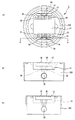
図3(a)は、図2を用いて説明した本発明のレジスト除去装置における反応部の1実施形態を模式的に示す平面図であり、(b)は、(a)に示す反応部の正面図であり、(c)は、(a)に示す反応部のA−A線断面図である。
なお、図3において、変換部材は省略している。
【0026】
図3(a)〜(c)に示すように、本実施形態の反応部8は、略円板状の本体部300から構成されている。
本体部300の上面には、その中央付近に平面視略長方形で凹状のホルダー保持部31が設けられるとともに、その外周付近に溝状の流入側貯留部33と流出側貯留部37とがホルダー保持部31を介してホルダー保持部31の側面に平行に設けられており、更に、流入側貯留部33とホルダー保持部31との間に複数の平行な流入溝32、及び、流出側貯留部37とホルダー保持部31との間に複数の平行な流出溝36が設けられている。
また、本体部300の内部には、その一端部が本体部300の流入側貯留部33付近の側面に露出し、その他端部が流入側貯留部33の直下部分にまで延設された流入管35と、その一端部が本体部300の流出側貯留部37付近の側面に露出し、その他端部が流出側貯留部37の直下部分にまで延設された流出管39とが設けられており、流入管35の上記他端部付近と流入側貯留部33とは、断面視V字型の流入路34により流通が図られており、流出管39の上記他端部付近と流出側貯留部37とは、断面視V字型の流出路38により流通が図られている。
【0027】
上記構造の反応部8において、ホルダー保持部31には、その表面にレジストを有する基板を保持、固定することができるホルダー(固定部)が嵌合される。
図4(a)は、上記ホルダーの一例を模式的に示す平面図であり、(b)は、(a)に示すホルダーの正面図である。
【0028】
図4(a)及び(b)に示すように、本発明のレジスト除去装置におけるホルダー40は、略板状の本体部42の上面に溝状の保持部41が設けられており、断面視略U字形状である。
【0029】
ホルダー40は、反応部8の流入溝32から基板表面のレジスト上へのオゾン水の流入、及び、流出溝36へのオゾン水の流出をスムーズに行うために、ホルダー40の保持部41の溝方向と反応部8の流入溝32及び流出溝36の溝方向とが同一方向となるように反応部8のホルダー保持部31へ嵌合される。
【0030】
本発明のレジスト除去装置の反応部8では、上記変換部材は、ホルダー保持部31に嵌合されたホルダー40の上記基板の処理面に対向する位置に、本体部300を覆う蓋体で、該蓋体の下面(基板との対向面)に断面3角形の凸条が複数形成された変換部材の上記凸条がオゾン水流の流れと直交するように配設される。
【0031】
上記構成の反応部8において、オゾン水は、流入管35から流入路34を通って流入側貯留部33に貯留され、流入側貯留部33を満たした後、流入溝32を通ってホルダー保持部31に嵌合されたホルダー40の保持部41上に固定された基板の処理面と、上記変換部材との間に均一、かつ、平行に流入される。そして、上記オゾン水は、上記基板表面のレジストを除去した後、流出溝36から流出側貯留部37に集められ、流出路38を通って流出管39から排出される。なお、流入管35は、図2におけるオゾン水流入口82と流通が図られており、流出管39は、オゾン水流出口81と流通が図られている。
【0032】
また、図3には示していないが、反応部8の本体部300のホルダー保持部31が設けられた側の面には、ホルダー保持部31、流入溝32、流入側貯留部33、流出溝36及び流出側貯留部37をその内部に収納することができる蓋部を取り付けることができるようになっており、上述した基板表面のレジストの除去を上記蓋部の内部で行うことができる。この場合、反応部8は、密閉型反応部となり、本発明のレジスト除去装置内を加圧し、過飽和のオゾン水を用いて基板表面のレジストの除去を行うことができる。
【0033】
本発明のレジスト剥離装置において、基板表面のレジストを除去する際のオゾン水の流量としては特に限定されず、基板の大きさや温度、変換部材と基板との距離や変換部材の模様等の条件により適宜決定されるが、好ましい下限は0.7L/分であり、好ましい上限は1.0L/分である。オゾン水の流量が0.7L/分未満であると、効率よくレジストを除去することができず、基板表面のレジストを完全に除去するのに長時間を要することがある。一方、流量が1.0L/分を超えると、もはやオゾン水の流量を増やしてもレジスト除去速度は向上せず、オゾン水の使用量に対するレジスト除去の効率が低下することがある。より好ましい下限は0.9L/分である。
【0034】
反応部8を構成する材料としては、耐オゾン性を有するものであれば特に限定されないが、例えば、上記変換部材と同様のフッ素系樹脂からなるものが好適である。
【0035】
本発明のレジスト除去装置における反応部は、図3に示した反応部8のように略円板状に限定されることはなく、例えば、板状等任意の形状が挙げられる。また、ホルダー40の保持部41の深さを調整することにより、基板の処理面上を流れるオゾン水の水深を調整することができる。
なお、本発明のレジスト除去装置における反応部の構造は、その表面にレジストを有する基板を固定部に保持、固定し、該基板の処理面に対向する位置に上述した変換部材を配設することができ、上記基板の処理面と上記変換部材との間にオゾン水を流通させることができる構造であれば特に図3に示す構造に限定されない。
【0036】
図5は、本発明のレジスト除去装置における反応部の別の一例を模式的に示す部分断面斜視図である。
図5に示す反応部50は、円板状の支持台と基板52を固定する真空チャックとからなる固定部54とその中心に筒状のオゾン水供給管55が嵌挿されたドーナツ状の変換部材53とが対向するように構成されており、変換部材53の固定部54側の面には、図1に示した波形部と略同形状の波形部53aが同心円状に形成されている。
基板52は、固定部54の変換部材53側の面上に保持、固定されるようになっており、変換部材53は、基板52の処理面と波形部53aとの間が所定の間隔となる位置に固定される。
【0037】
このような反応部50において、オゾン水は、オゾン水供給管55から変換部材53と基板52の処理面との間の基板52の中心付近に供給された後、基板52の外縁方向へ広がるように流れる。その際、オゾン水流には、変換部材53の波形部53aにより乱流が生じるため、基板52の外縁部分付近であっても、常に高濃度のオゾン水が当たることとなり、均一にしかも高い効率で基板表面のレジストを除去することができる。
【0038】
反応部50を構成する、変換部材53及び固定部54等を構成する材料としては、図3及び図4に示した反応部8の変換部材及び固定部と同様の材料を挙げることができる。
【0039】
このような反応部50は、その大きさを基板の大きさと略同じとすることができるため、大口径の基板表面のレジストを除去する場合であっても、レジスト除去装置の大型化を抑制することができるとともに、高効率でかつ均一に大口径の基板表面のレジストを除去することができる。
また、上記構造の反応部は、通常、開放型(オープン)反応部として使用するが、上記構造の反応部を密閉容器中に設置して密閉型反応部としてもよい。
【0040】
本発明のレジスト除去装置を用いることにより、高い効率でレジスト除去を行うことができる。本発明のレジスト除去装置を用いるレジスト除去方法もまた、本発明の1つである。
【0041】
【実施例】
以下に実施例を掲げて本発明を更に詳しく説明するが、本発明はこれら実施例のみに限定されるものではない。
【0042】
(実施例1)
図6(a)及び(b)に示したような、30mm×30mmの範囲に、45°の角度の斜部を有する高さ1.7mmの波形部が10連続する構造の変換部材を作製した。なお、図6(a)は、実施例1に係る反応部における変換部材の一部を模式的に示す断面図であり、(b)は、その平面図である。
この変換部材を用いて図2〜図4に示した構成の反応部を作製した。ここで、変換部材とウエハとの距離は0.3mmとした。
なお、ウエハとしては、予めレジスト液(富士フィルムアーチ社製、HPR−204LT)を塗布し、スピンコーター(ミカサ社製、1H−DX2型)にて2000rpm、30秒間処理した後、更に90℃20分間乾燥して、厚さ約1.0μmのレジストがコートし、30mm×30mmの大きさにカットしたものを用いた。
【0043】
この反応部に21℃、50ppmの濃度のオゾン水を1.0L/minの流速で流し、膜厚計(大塚電子社製、FE−3000型)を用いて、経時的にレジストの厚さを測定して、レジスト除去速度を算出した。
この結果を表1に示した。
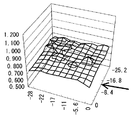
また、膜厚計(大塚電子社製、FE−3000型)を用いて得られたデータから測定開始20秒後のレジストの厚さを示す3次元図を図8に示した。なお、図8に示した矢印は、オゾン水流の流れの方向を示す。
【0044】
(実施例2)
オゾン水の流量を1.9L/minとした以外は実施例1と同様にしてレジスト除去を行った。
結果を表1及び図9に示した。なお、図9に示した矢印は、オゾン水流の流れの方向を示す。
【0045】
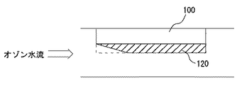
(比較例1)
図7に示したような、変換部材を設置しない構成の反応部を作製した。これを用いた以外は実施例1と同様にしてレジスト除去を行った。なお、図7は、比較例1に係る反応部を模式的に示す断面図であり、70は反応部を示し、71はウエハを示し、72はレジストを示している。
結果を表1及び図10に示した。なお、図10に示した矢印は、オゾン水流の流れの方向を示す。
【0046】
【表1】

表1より、実施例1、2の方が比較例1に比べて高いレジスト除去速度が得られることがわかった。
また、図8〜10より、実施例1、2ではオゾン水流の方向に関わらず略均一にレジストが除去されていたのに対して、比較例1ではオゾン水流の流入側と流出側とでレジストの除去に著しい差があった。
【0048】
【発明の効果】
本発明によれば、基板表面のレジストを高効率かつ均一に除去することができるレジスト除去装置及びレジスト除去方法を提供できる。
【図面の簡単な説明】
【図1】本発明のレジスト除去装置の反応部の一実施態様を示す断面図である。
【図2】本発明のレジスト除去装置の1実施形態を示す概略図である。
【図3】(a)は、本発明のレジスト除去装置の反応部の一例を模式的に示す平面図であり、(b)は、(a)に示す反応部の断面図であり、(c)は、(a)に示す反応部のA−A線断面図である。
【図4】(a)は、図3に示す反応部のホルダー保持部に嵌合させるホルダーの一例を模式的に示す平面図であり、(b)は、(a)に示すホルダーの正面図である。
【図5】本発明のレジスト除去装置における反応部の別の一例を模式的に示す斜視図である。
【図6】(a)は、実施例1及び2で用いた変換部材の一部を模式的に示す断面図であり、(b)は、その平面図である。
【図7】比較例1で用いた反応部を模式的に示す断面図である。
【図8】実施例1における測定開始20秒後のレジストの厚さを示す3次元図である。
【図9】実施例2における測定開始20秒後のレジストの厚さを示す3次元図である。
【図10】比較例1における測定開始20秒後のレジストの厚さを示す3次元図である。
【図11】従来のレジスト除去装置におけるレジスト除去の様子を示す模式図である。
【符号の説明】
1、51 基板
2 レジスト
3、53 変換部材
3a、53a 波形部
4 オゾン発生器
5 オゾンガス検出器
6 オゾン溶解モジュール
61 オゾン水流出口
62 オゾン水流入口
7 オゾン水検出器
8、30、50 反応部
9 循環ポンプ
10 往路管
11 復路管
31 ホルダー保持部
32 流入溝
33 流入側貯留部
34 流入路
35 流入管
36 流出溝
37 流出側貯留部
38 流出路
39 流出管
40 ホルダー
41 保持部
42 本体部
54 固定部材
55 オゾン水供給管
81 オゾン水流出口
82 オゾン水流入口
300 本体部[0001]
TECHNICAL FIELD OF THE INVENTION
The present invention relates to a resist removing apparatus and a resist removing method capable of removing a resist on a substrate surface with high efficiency.
[0002]
[Prior art]
When a circuit is formed on a semiconductor substrate or when a plurality of colored pixels having different hues are formed in a pattern on a liquid crystal substrate, a photolithography step is an essential step. For example, in the case of forming a circuit on a semiconductor substrate, a resist is applied on the substrate, an image formed of a resist pattern is formed by a normal photo process, and after etching using the image as a mask, the unnecessary resist is removed. In order to form a circuit by removing the resist, a resist is applied again to form the next circuit, and a cycle of image formation, etching and removal of the resist is repeated.
[0003]
Conventionally, in a resist removing step of removing unnecessary resist, an asher (ashing means) or an RCA cleaning method using sulfuric acid, hydrogen peroxide, or the like has been used for removing a resist from a semiconductor substrate. For removing the resist from the substrate, a mixed solution of an organic solvent and an amine has been used. However, if an asher is used to remove the resist, the semiconductor may be damaged due to the high temperature, and inorganic impurities cannot be removed. In addition, when using a solvent or chemicals to remove resist, a new chemical must be replaced every ten or more batches, which requires a large amount of chemicals, increases the cost of chemicals, and generates a large amount of waste liquid. Also, there is a great disadvantage in terms of cost and environment in treating waste liquid.
[0004]
Ozone water obtained by dissolving ozone gas in water exerts excellent effects on sterilization, deodorization, bleaching, etc. due to the strong oxidizing power of ozone, and the ozone gas self-decomposes into harmless oxygen (gas) over time. Since it has no residual properties, it is attracting attention as an environmentally friendly sterilizing, washing, and bleaching agent. In recent years, with increasing interest in the environment, a resist removal process using ozone water has attracted attention as an alternative to the above-described resist removal method.
[0005]
As a resist removal device using ozone water, for example, a device that installs a substrate in a flow path of an ozone water flow, a device that injects ozone water in a shower shape or a mist shape on a processing surface of the substrate, and the like were considered. In any case, there was a problem that a practical resist removal rate could not be obtained, or that the resist could not be uniformly removed over the entire surface of the substrate. In addition, since it is difficult to produce a large amount of high-concentration ozone water, there has been a demand for removing the resist efficiently with a smaller amount of ozone water.
[0006]
Patent Literature 1 discloses a method in which an object to be cleaned is diagonally immersed in a liquid in which ozone is dissolved, and the object to be cleaned is irradiated with ultraviolet light. Patent Document 2 discloses a method in which ozone gas is pressurized. A method is disclosed in which ozone water produced by dissolving in water with pure water is guided to a closed cleaning chamber containing the object to be cleaned while maintaining the pressure, and the object to be cleaned is cleaned.
In the method of cleaning an object to be cleaned using ozone water disclosed in Patent Literatures 1 and 2, the cleaning ability of the object to be cleaned is improved by irradiating the object to be cleaned with ultraviolet light or applying pressure. However, when attempting to remove the resist on the substrate surface by these methods, it is difficult to say that a sufficient resist removal rate can be obtained, and it is very difficult to uniformly remove the resist on the substrate surface. there were.
[0007]
[Patent Document 1]
Japanese Patent No. 3016301 [Patent Document 2]
JP 2001-79502 A
[Problems to be solved by the invention]
The present invention has been made in view of the above circumstances, and has as its object to provide a resist removing apparatus and a resist removing method capable of removing a resist on a substrate surface with high efficiency and uniformity.
[0009]
[Means for Solving the Problems]
The present invention is a resist removal apparatus that removes a resist on the substrate surface by flowing ozone water along a processing surface of the substrate, wherein at least the processing surface of the substrate is substantially in the direction of the flow of the ozone water. A resist stripper having a reaction part comprising a fixing part for fixing the substrate so as to be parallel and a conversion member provided at a position facing the processing surface of the fixed substrate and changing the direction of the flow of ozone water. Device.
Hereinafter, the present invention will be described in detail.
[0010]
The resist removing apparatus of the present invention removes the resist on the surface of the substrate by flowing ozone water along the processing surface (main surface) of the substrate.
In the present specification, the ozone water includes not only a solution obtained by dissolving ozone gas in an aqueous solution but also a solution obtained by dissolving ozone gas in water in which an organic acid such as acetic acid or a derivative thereof is dissolved.
The substrate is not particularly limited, and examples thereof include various silicon wafers used for semiconductor devices, glass substrates used for display panels, and other resin substrates.
[0011]
The resist removing apparatus according to the present invention includes: a fixing unit that fixes a substrate so that a processing surface (main surface) of the substrate is substantially parallel to a direction of an ozone water flow (hereinafter, also referred to as an ozone water flow); A reaction member, which is provided at a position facing the processing surface of the substrate and is configured to change the direction of the ozone water flow. By using such a resist removing apparatus of the present invention, the resist can be removed uniformly and with high efficiency.
[0012]
When the present inventors examined a conventional resist removing apparatus that installs a substrate in the flow path of the ozone water flow, as shown in FIG. 11, the
The saturated concentration of ozone water at room temperature is as low as about 60 ppm, and the concentration of ozone water immediately decreases upon reaction with the resist. When the ozone water flows in the tube as a parallel water flow with respect to the surface direction of the substrate, the ozone water near the substrate processing surface that hit the resist on the inflow side consumes ozone to remove the resist there, and the ozone concentration decreases. Since the ozone water having a reduced ozone concentration flows directly near the processing surface of the substrate, it is considered that the ozone water no longer has an ozone concentration enough to remove the resist at the outflow side. On the other hand, it is considered that ozone water flowing at a position relatively far from the processing surface of the substrate flows away almost without being used for resist removal.
[0013]
In the reaction unit of the resist removing apparatus of the present invention, a conversion member for changing the direction of the ozone water flow is provided at a position facing the processing surface of the substrate fixed to the fixing unit so as to be substantially parallel to the direction of the ozone water flow. By providing, even if ozone is consumed on the inflow side of the ozone water flow, turbulence occurs in the ozone water flow due to the stirring effect of the conversion member, and high concentration ozone water always hits the entire processing surface of the substrate. The resist can be removed with high efficiency. In particular, when a conversion member having a shape that generates a turbulent flow such that the direction of the ozone water flow converted by the conversion member is directed toward substantially the entire processing surface of the substrate is selected, the resist can be formed with extremely high efficiency. Can be removed.
[0014]
The shape of the conversion member is not particularly limited, and examples thereof include a rod shape having a round or polygonal cross section, a mesh member, and a corrugated plate. Above all, it is preferable that the conversion member 3 shown in FIG. 1 has a structure in which a corrugated portion 3a having an oblique portion with respect to the direction of the ozone water flow is continuous in the direction of the ozone water flow. If the conversion member 3 having such a shape is used, an ozone water flow directed toward the entire processing surface of the substrate 1 is efficiently generated, so that a high-concentration ozone water reaches the resist 2 on the entire processing surface of the substrate 1. And the resist 2 can be removed with higher efficiency. FIG. 1 is a schematic view showing one embodiment of the reaction section of the resist removing apparatus of the present invention.
The angle of the oblique portion of the corrugated portion 3a is not particularly limited. However, if the angle is too small, the ozone water flow toward the processing surface of the substrate 1 is not generated, and the above-described effects may not be sufficiently obtained.
Further, the conversion member may be integrated with a member constituting the flow path of the ozone water (for example, a container or a partition in which the substrate is stored) or may be separate.
[0015]
In the resist removing apparatus of the present invention, the distance between the conversion member and the processing surface of the substrate is preferably 1.5 mm or less. If the thickness exceeds 1.5 mm, the effect of the turbulent flow of the ozone water flow by the conversion member may be difficult to reach the processing surface of the substrate, and the resist removal rate may be insufficient. It is more preferably 0.5 mm or less, and still more preferably 0.3 mm. The distance between the conversion member and the processing surface of the substrate means the distance between the closest points between the conversion member and the processing surface of the substrate.
[0016]
The material constituting the conversion member is not particularly limited as long as it has ozone resistance, and for example, a material made of a fluororesin is suitable. Examples of the fluorine resin include tetrafluoroethylene copolymers such as polytetrafluoroethylene resin (PTFE), perfluoroalkoxy resin (PFA), and fluoroethylene propylene resin (FEP); and fluorine rubber. Can be
[0017]
Further, it is preferable that the conversion member is disposed so as to oppose substantially the entire processing surface of the substrate, or has a size that opposes substantially the entire processing surface of the substrate. Since the ozone water flow toward the entire processing surface of the substrate can be more reliably generated, the chance of the ozone water reaching the resist on the entire surface of the substrate increases with a high probability, and the resist can be more reliably removed. It is.
[0018]
In the resist removing apparatus of the present invention, the substrate is fixed to the fixing part such that the processing surface is substantially parallel to the flow direction of the ozone water.
Means for fixing the substrate to the fixing portion so that the processing surface is substantially parallel to the flow direction of the ozone water is not particularly limited, and for example, a method of fixing the substrate to the fixing portion by an adhesive means such as a double-sided tape; A method of fitting a holder (fixed portion) on which a substrate is mounted to a holder holding portion; a vacuum chucking method of adsorbing a substrate to the fixed portion with a vacuum pump;
[0019]
BEST MODE FOR CARRYING OUT THE INVENTION
Hereinafter, the present invention will be described based on embodiments.
FIG. 2 is a schematic view showing one embodiment of the resist removing apparatus of the present invention.
The resist removing apparatus of the embodiment shown in FIG. 2 includes an ozone generator 4, an ozone gas detector 5, an ozone dissolving module 6, an ozone water concentration detector 7, a reaction unit 8, and a pump 9.
[0020]
In the ozone generator 4, ozone gas is generated. The ozone generator 4 is not particularly limited, and a known ozone generator can be used. The concentration of the ozone gas generated by the ozone generator 4 is measured and monitored by the ozone gas detector 5. The value of the ozone gas concentration measured by the ozone gas detector 5 is fed back to the ozone generator 4, and the concentration of the ozone gas generated by the ozone generator 4 is adjusted as needed.
[0021]
The ozone gas generated by the ozone generator 4 is dissolved in water in the ozone dissolving module 6.
The ozone dissolving module 6 preferably contains a gas permeable membrane made of a non-porous membrane. If such an ozone dissolving module is used, clogging does not occur even if the ozone water once used for removing the resist is circulated and used again.
The ozone water generated in the ozone dissolving module 6 is discharged from the
[0022]
The obtained ozone water is sent from the ozone
Further, the reaction unit 8 may be provided with a unit for irradiating ultraviolet rays. When the resist on the substrate surface is removed, irradiation with ultraviolet rays accelerates the decomposition rate of ozone, and accordingly, the effect of removing the resist can be enhanced. Therefore, by using ozone water and ultraviolet irradiation together, a higher resist removal effect can be obtained.
The means for irradiating the ultraviolet rays is not particularly limited, and examples thereof include a UV lamp. The wavelength of the irradiated ultraviolet light is preferably around 254 nm, which is absorbed by ozone.
[0023]
In the resist removing apparatus of the present invention, it is preferable to circulate and use the generated ozone water. By circulating and using the ozone water, a necessary amount of the ozone water can be saved, and a higher concentration ozone water can be easily obtained.
In order to circulate the ozone water, for example, the ozone water discharged from the
[0024]
Further, the resist removing apparatus of the present invention preferably has a means for heating ozone water. Since the resist removal is performed by a chemical reaction between the resist and ozone, it is possible to increase the resist removal rate by applying a temperature.
Further, it is preferable that the resist removing apparatus of the present invention has means for pressurizing the inside of the apparatus. By pressurizing the inside of the apparatus, supersaturated ozone water can be generated, and by using such high concentration ozone water, the resist can be removed with higher efficiency.
[0025]
FIG. 3A is a plan view schematically showing one embodiment of the reaction unit in the resist removing apparatus of the present invention described with reference to FIG. 2, and FIG. 3B is a plan view of the reaction unit shown in FIG. It is a front view, (c) is an AA sectional view of the reaction part shown in (a).
In FIG. 3, the conversion member is omitted.
[0026]
As shown in FIGS. 3A to 3C, the reaction section 8 of the present embodiment includes a substantially disk-shaped
On the upper surface of the
In addition, inside the
[0027]
In the reaction section 8 having the above structure, a holder (fixing section) capable of holding and fixing a substrate having a resist on its surface is fitted into the
FIG. 4A is a plan view schematically showing an example of the holder, and FIG. 4B is a front view of the holder shown in FIG.
[0028]
As shown in FIGS. 4A and 4B, the
[0029]
The
[0030]
In the reaction unit 8 of the resist removing apparatus of the present invention, the conversion member is a lid that covers the
[0031]
In the reaction unit 8 having the above-described configuration, the ozone water is stored in the inflow-
[0032]
Although not shown in FIG. 3, the
[0033]
In the resist stripping apparatus of the present invention, the flow rate of ozone water when removing the resist on the substrate surface is not particularly limited, and depends on conditions such as the size and temperature of the substrate, the distance between the conversion member and the substrate, and the pattern of the conversion member. Although determined appropriately, a preferred lower limit is 0.7 L / min, and a preferred upper limit is 1.0 L / min. If the flow rate of the ozone water is less than 0.7 L / min, the resist cannot be efficiently removed, and it may take a long time to completely remove the resist on the substrate surface. On the other hand, when the flow rate exceeds 1.0 L / min, even if the flow rate of the ozone water is increased, the resist removal speed is not improved, and the efficiency of the resist removal with respect to the usage amount of the ozone water may be reduced. A more preferred lower limit is 0.9 L / min.
[0034]
The material constituting the reaction section 8 is not particularly limited as long as it has ozone resistance. For example, a material made of the same fluorine resin as the above-mentioned conversion member is preferable.
[0035]
The reaction section in the resist removing apparatus of the present invention is not limited to a substantially disk shape as in the reaction section 8 shown in FIG. 3, but may be any shape such as a plate shape. Further, by adjusting the depth of the holding
The structure of the reaction section in the resist removing apparatus of the present invention is such that a substrate having a resist on its surface is held and fixed on a fixing section, and the above-described conversion member is disposed at a position facing the processing surface of the substrate. The structure is not particularly limited to the structure shown in FIG. 3 as long as ozone water can flow between the processing surface of the substrate and the conversion member.
[0036]
FIG. 5 is a partial cross-sectional perspective view schematically showing another example of the reaction section in the resist removing apparatus of the present invention.
The
The
[0037]
In such a
[0038]
As a material for forming the
[0039]
Since the size of the
The reaction section having the above structure is usually used as an open reaction section. However, the reaction section having the above structure may be provided in a closed vessel to form a closed reaction section.
[0040]
By using the resist removing apparatus of the present invention, the resist can be removed with high efficiency. A method for removing a resist using the resist removing apparatus of the present invention is also one of the present invention.
[0041]
【Example】
Hereinafter, the present invention will be described in more detail with reference to Examples, but the present invention is not limited to these Examples.
[0042]
(Example 1)
As shown in FIGS. 6 (a) and 6 (b), a conversion member having a structure in which a waveform portion having a slope of 45 ° and a height of 1.7 mm and ten continuous portions was formed in a range of 30 mm × 30 mm as shown in FIGS. . FIG. 6A is a cross-sectional view schematically illustrating a part of the conversion member in the reaction unit according to the first embodiment, and FIG. 6B is a plan view thereof.
Using this conversion member, a reaction section having the configuration shown in FIGS. Here, the distance between the conversion member and the wafer was 0.3 mm.
The wafer was previously coated with a resist solution (HPR-204LT, manufactured by Fuji Film Arch Co., Ltd.), treated with a spin coater (manufactured by Mikasa, 1H-DX2 type) at 2,000 rpm for 30 seconds, and then further heated to 90 ° C. 20 After drying for about a minute, a resist coated with a thickness of about 1.0 μm and cut into a size of 30 mm × 30 mm was used.
[0043]
Ozone water at a concentration of 50 ppm is flowed at a flow rate of 1.0 L / min at 21 ° C. into the reaction section, and the thickness of the resist is gradually changed with time using a film thickness meter (manufactured by Otsuka Electronics Co., Ltd., FE-3000 type). The measurement was performed to calculate the resist removal rate.
The results are shown in Table 1.
FIG. 8 shows a three-dimensional diagram showing the thickness of the resist 20 seconds after the start of measurement based on data obtained using a film thickness meter (manufactured by Otsuka Electronics Co., Ltd., FE-3000 type). The arrow shown in FIG. 8 indicates the direction of the flow of the ozone water flow.
[0044]
(Example 2)
The resist was removed in the same manner as in Example 1 except that the flow rate of the ozone water was set to 1.9 L / min.
The results are shown in Table 1 and FIG. The arrow shown in FIG. 9 indicates the direction of the ozone water flow.
[0045]
(Comparative Example 1)
As shown in FIG. 7, a reaction section having a configuration in which the conversion member was not installed was manufactured. Except for using this, the resist was removed in the same manner as in Example 1. FIG. 7 is a cross-sectional view schematically showing a reaction section according to Comparative Example 1, where 70 indicates a reaction section, 71 indicates a wafer, and 72 indicates a resist.
The results are shown in Table 1 and FIG. The arrow shown in FIG. 10 indicates the direction of the flow of the ozone water flow.
[0046]
[Table 1]
From Table 1, it was found that Examples 1 and 2 can obtain a higher resist removal rate than Comparative Example 1.
8 to 10, the resist was removed substantially uniformly regardless of the direction of the ozone water flow in Examples 1 and 2, whereas the resist was removed on the inflow side and the outflow side of the ozone water flow in Comparative Example 1. There was a significant difference in the removal of
[0048]
【The invention's effect】
ADVANTAGE OF THE INVENTION According to this invention, the resist removal apparatus and the resist removal method which can remove the resist of a substrate surface efficiently and uniformly can be provided.
[Brief description of the drawings]
FIG. 1 is a cross-sectional view showing one embodiment of a reaction section of a resist removing apparatus of the present invention.
FIG. 2 is a schematic view showing one embodiment of a resist removing apparatus of the present invention.
3A is a plan view schematically showing an example of a reaction section of the resist removing apparatus of the present invention, FIG. 3B is a cross-sectional view of the reaction section shown in FIG. () Is a sectional view taken along line AA of the reaction section shown in (a).
4A is a plan view schematically showing an example of a holder fitted into a holder holding portion of the reaction section shown in FIG. 3, and FIG. 4B is a front view of the holder shown in FIG. It is.
FIG. 5 is a perspective view schematically showing another example of the reaction section in the resist removing apparatus of the present invention.
FIG. 6A is a cross-sectional view schematically showing a part of the conversion member used in Examples 1 and 2, and FIG. 6B is a plan view thereof.
FIG. 7 is a cross-sectional view schematically showing a reaction section used in Comparative Example 1.
FIG. 8 is a three-dimensional diagram showing the thickness of a resist 20 seconds after the start of measurement in Example 1.
FIG. 9 is a three-dimensional view showing the thickness of a resist 20 seconds after the start of measurement in Example 2.
FIG. 10 is a three-dimensional diagram showing the thickness of a resist 20 seconds after the start of measurement in Comparative Example 1.
FIG. 11 is a schematic diagram showing a state of resist removal in a conventional resist removal apparatus.
[Explanation of symbols]
1, 51 Substrate 2 Resist 3, 53
Claims (4)
少なくとも、オゾン水の流れの方向に対して前記基板の処理面が略平行になるように前記基板を固定する固定部と、固定された前記基板の処理面に対向する位置に設けられ、オゾン水の流れの方向を変換する変換部材とからなる反応部を有する
ことを特徴とするレジスト除去装置。A resist removing apparatus that removes resist on the surface of the substrate by flowing ozone water along a processing surface of the substrate,
At least a fixing portion for fixing the substrate so that the processing surface of the substrate is substantially parallel to the flow direction of the ozone water; and a fixing portion provided at a position opposed to the processing surface of the fixed substrate. And a conversion member for changing the direction of flow of the resist.
Priority Applications (1)
| Application Number | Priority Date | Filing Date | Title |
|---|---|---|---|
| JP2002375288A JP2004207515A (en) | 2002-12-25 | 2002-12-25 | Device and method for removing resist |
Applications Claiming Priority (1)
| Application Number | Priority Date | Filing Date | Title |
|---|---|---|---|
| JP2002375288A JP2004207515A (en) | 2002-12-25 | 2002-12-25 | Device and method for removing resist |
Publications (1)
| Publication Number | Publication Date |
|---|---|
| JP2004207515A true JP2004207515A (en) | 2004-07-22 |
Family
ID=32813074
Family Applications (1)
| Application Number | Title | Priority Date | Filing Date |
|---|---|---|---|
| JP2002375288A Pending JP2004207515A (en) | 2002-12-25 | 2002-12-25 | Device and method for removing resist |
Country Status (1)
| Country | Link |
|---|---|
| JP (1) | JP2004207515A (en) |
Cited By (4)
| Publication number | Priority date | Publication date | Assignee | Title |
|---|---|---|---|---|
| WO2004095550A1 (en) * | 2003-04-21 | 2004-11-04 | Sekisui Chemical Co. Ltd. | Organic matter removing apparatus, organic matter removing method, ozone water jet nozzle, and organic matter removing apparatus for mask substrate |
| JP2006173211A (en) * | 2004-12-13 | 2006-06-29 | Sekisui Chem Co Ltd | Method and device for removing resist |
| WO2012073574A1 (en) * | 2010-11-30 | 2012-06-07 | シャープ株式会社 | Method for removal of photoresist |
| US9117854B2 (en) * | 2010-03-10 | 2015-08-25 | Tokyo Electron Limited | Substrate processing apparatus, substrate processing method, and storage medium storing a computer program for performing substrate processing method |
-
2002
- 2002-12-25 JP JP2002375288A patent/JP2004207515A/en active Pending
Cited By (7)
| Publication number | Priority date | Publication date | Assignee | Title |
|---|---|---|---|---|
| WO2004095550A1 (en) * | 2003-04-21 | 2004-11-04 | Sekisui Chemical Co. Ltd. | Organic matter removing apparatus, organic matter removing method, ozone water jet nozzle, and organic matter removing apparatus for mask substrate |
| JP2006173211A (en) * | 2004-12-13 | 2006-06-29 | Sekisui Chem Co Ltd | Method and device for removing resist |
| US9117854B2 (en) * | 2010-03-10 | 2015-08-25 | Tokyo Electron Limited | Substrate processing apparatus, substrate processing method, and storage medium storing a computer program for performing substrate processing method |
| WO2012073574A1 (en) * | 2010-11-30 | 2012-06-07 | シャープ株式会社 | Method for removal of photoresist |
| JP2012119491A (en) * | 2010-11-30 | 2012-06-21 | Sharp Corp | Photoresist removing method |
| CN103003919A (en) * | 2010-11-30 | 2013-03-27 | 夏普株式会社 | Method for removal of photoresist |
| US20130233357A1 (en) * | 2010-11-30 | 2013-09-12 | Sharp Kabushiki Kaisha | Method for removing photoresist |
Similar Documents
| Publication | Publication Date | Title |
|---|---|---|
| US6613692B1 (en) | Substrate processing method and apparatus | |
| KR20120033250A (en) | Substrate processing apparatus and substrate processing method | |
| JP2008034779A (en) | Method and equipment for processing substrate | |
| US20040154641A1 (en) | Substrate processing apparatus and method | |
| TW582065B (en) | Apparatus for cleaning semiconductor wafer and method for cleaning wafer using the same | |
| US9773688B2 (en) | Ultrasonic cleaning method and ultrasonic cleaning apparatus | |
| KR20130132277A (en) | Ultrasonic cleaning method and ultrasonic cleaning apparatus | |
| TWI304602B (en) | ||
| JP2004207515A (en) | Device and method for removing resist | |
| JPH10116809A (en) | Method and system for washing | |
| JP2008311256A (en) | Photoresist removing device | |
| JP2002096012A (en) | Device for treating substrate | |
| WO2017170595A1 (en) | Cleaning method, cleaning liquid, and cleaning device | |
| JP2009110984A (en) | Substrate processing method and substrate processing apparatus | |
| JP4351862B2 (en) | Resist removing method and resist removing apparatus | |
| JP4177092B2 (en) | Resist removing apparatus and resist removing method | |
| JP2891578B2 (en) | Substrate processing method | |
| TW201402236A (en) | Ultrasonic cleaning method and ultrasonic cleaning apparatus | |
| JP2001203182A (en) | Cleaning method of object surface and cleaning equipment for method | |
| JP2006164996A (en) | Resist removing apparatus for mask substrate | |
| JP7202632B2 (en) | SUBSTRATE PROCESSING APPARATUS AND SUBSTRATE PROCESSING METHOD | |
| JPH0458527A (en) | Cleaning method | |
| JP2005129865A (en) | Ozone water use system | |
| JPH0547730A (en) | Removing method for organic material | |
| WO2004095550A1 (en) | Organic matter removing apparatus, organic matter removing method, ozone water jet nozzle, and organic matter removing apparatus for mask substrate |
Legal Events
| Date | Code | Title | Description |
|---|---|---|---|
| A621 | Written request for application examination |
Effective date: 20050810 Free format text: JAPANESE INTERMEDIATE CODE: A621 |
|
| A977 | Report on retrieval |
Free format text: JAPANESE INTERMEDIATE CODE: A971007 Effective date: 20061218 |
|
| A131 | Notification of reasons for refusal |
Effective date: 20080319 Free format text: JAPANESE INTERMEDIATE CODE: A131 |
|
| A02 | Decision of refusal |
Effective date: 20080709 Free format text: JAPANESE INTERMEDIATE CODE: A02 |