JP2004207231A - Electrolyte membrane-electrode junction body for fuel cell and fuel cell operating method using it - Google Patents
Electrolyte membrane-electrode junction body for fuel cell and fuel cell operating method using it Download PDFInfo
- Publication number
- JP2004207231A JP2004207231A JP2003409494A JP2003409494A JP2004207231A JP 2004207231 A JP2004207231 A JP 2004207231A JP 2003409494 A JP2003409494 A JP 2003409494A JP 2003409494 A JP2003409494 A JP 2003409494A JP 2004207231 A JP2004207231 A JP 2004207231A
- Authority
- JP
- Japan
- Prior art keywords
- electrolyte membrane
- carbon fiber
- woven fabric
- fuel cell
- fiber woven
- Prior art date
- Legal status (The legal status is an assumption and is not a legal conclusion. Google has not performed a legal analysis and makes no representation as to the accuracy of the status listed.)
- Pending
Links
Images

Classifications
-
- Y—GENERAL TAGGING OF NEW TECHNOLOGICAL DEVELOPMENTS; GENERAL TAGGING OF CROSS-SECTIONAL TECHNOLOGIES SPANNING OVER SEVERAL SECTIONS OF THE IPC; TECHNICAL SUBJECTS COVERED BY FORMER USPC CROSS-REFERENCE ART COLLECTIONS [XRACs] AND DIGESTS
- Y02—TECHNOLOGIES OR APPLICATIONS FOR MITIGATION OR ADAPTATION AGAINST CLIMATE CHANGE
- Y02E—REDUCTION OF GREENHOUSE GAS [GHG] EMISSIONS, RELATED TO ENERGY GENERATION, TRANSMISSION OR DISTRIBUTION
- Y02E60/00—Enabling technologies; Technologies with a potential or indirect contribution to GHG emissions mitigation
- Y02E60/30—Hydrogen technology
- Y02E60/50—Fuel cells
Landscapes
- Fuel Cell (AREA)
- Inert Electrodes (AREA)
Abstract
Description
本発明は、プロトン伝導性高分子電解質膜を用いる高分子電解質型燃料電池の電解質膜―電極接合体、およびこの電解質膜―電極接合体を用いた燃料電池の運転方法に関するものである。 The present invention relates to an electrolyte membrane-electrode assembly for a polymer electrolyte fuel cell using a proton conductive polymer electrolyte membrane, and a method for operating a fuel cell using the electrolyte membrane-electrode assembly.
一般的に高分子電解質型燃料電池(以下、PEFCで表す)の電解質膜―電極接合体(以下、MEAで表す)は、高分子電解質膜および高分子電解質膜を挟む一対の電極からなっている。これら電極は高分子電解質膜に接する触媒層、および触媒層に接する撥水層を有するガス拡散層からなっている。MEAをその外側の両面からガス流路を備えたセパレータ板により挟持し、ガスリークを防ぐためのシール材と共に一定の圧力により締結してPEFCの単電池が構成される。 Generally, an electrolyte membrane-electrode assembly (hereinafter, referred to as MEA) of a polymer electrolyte fuel cell (hereinafter, referred to as PEFC) includes a polymer electrolyte membrane and a pair of electrodes sandwiching the polymer electrolyte membrane. . These electrodes include a catalyst layer in contact with the polymer electrolyte membrane and a gas diffusion layer having a water-repellent layer in contact with the catalyst layer. The MEA is sandwiched between separator plates provided with gas flow paths from both outer surfaces thereof and fastened together with a sealing material for preventing gas leakage under a certain pressure to form a PEFC cell.
セパレータ板には反応ガス(燃料ガスまたは酸化剤ガス)の供給口から排出口へかけて溝(ガス流路)が形成され、そのガス流路を反応ガスが流れる仕組みになっている。ガス拡散層に求められる機能は、ガス流路を通じて供給される反応ガスを拡散させて触媒層の全面に隈なく供給することである。さらにガス拡散層の機能としては、PEFC作動時の反応でカソード側触媒層に生成した水によって反応ガスの拡散性が阻害されないように、余剰水を排出させることが重要である。つまり、生成水をガス拡散層内の細孔に滞ることなく通過させ、セパレータ板のガス流路まで円滑に到達させることがガス拡散層の重要な機能である。そしてガス拡散層は、セパレータ板のガス流路の両側に形成されている凸部(リブ)と接してセパレータ板と電気的に導通しており、MEAで発生する電流をセパレータ板に導電する役割をもっている。 A groove (gas flow path) is formed in the separator plate from the supply port of the reaction gas (fuel gas or oxidant gas) to the discharge port, and the reaction gas flows through the gas flow path. The function required of the gas diffusion layer is to diffuse the reaction gas supplied through the gas flow path and supply the reaction gas to the entire surface of the catalyst layer. Further, as a function of the gas diffusion layer, it is important to discharge excess water so that the water generated in the cathode-side catalyst layer in the reaction during the operation of the PEFC does not inhibit the diffusibility of the reaction gas. That is, it is an important function of the gas diffusion layer to allow the generated water to pass through the pores in the gas diffusion layer without stagnation and to smoothly reach the gas flow path of the separator plate. The gas diffusion layer is in contact with the protrusions (ribs) formed on both sides of the gas flow path of the separator plate and is electrically connected to the separator plate, and serves to conduct current generated in the MEA to the separator plate. Have.
一般的に、触媒層と接する側のガス拡散層には撥水層が形成されており、撥水層の撥水材としてフッ素系樹脂が用いられている。撥水層には撥水材とともにカーボンなどの導電性材料が含まれている。従来の一般的な技術では、ガス拡散層の基材を多孔質構造とすることでガス拡散能力を確保し、撥水層をガス拡散層に形成することで、水の透過能力を制御し、さらに、炭素繊維、金属繊維などからなる電子導電性材料をガス拡散層の基材として用いることで電子導電性を確保している。一般的なガス拡散層の基材としては、カーボンペーパ、カーボンフェルトおよび炭素繊維織布などが用いられている。 Generally, a water-repellent layer is formed on the gas diffusion layer in contact with the catalyst layer, and a fluorine-based resin is used as a water-repellent material for the water-repellent layer. The water-repellent layer contains a conductive material such as carbon together with the water-repellent material. In the conventional general technology, the gas diffusion ability is secured by making the base material of the gas diffusion layer a porous structure, and the water permeation ability is controlled by forming the water-repellent layer on the gas diffusion layer, Furthermore, the electronic conductivity is ensured by using an electron conductive material made of carbon fiber, metal fiber, or the like as a base material of the gas diffusion layer. As a base material of a general gas diffusion layer, carbon paper, carbon felt, carbon fiber woven fabric, or the like is used.
カーボンペーパおよびカーボンフェルトには、目付け重量や厚みによるガス拡散性や水透過性などの特性の差はあるが、ランダムに配置された炭素繊維で構成されているため、繊維の配置の差による上記の特性の差は少ない。一方、炭素繊維織布は炭素繊維が規則正しく配置するように織られているため、目付け重量や厚み以外に、炭素繊維織布の織り方が上記特性の重要な支配因子となる。つまり、カーボンペーパおよびカーボンフェルトと異なり、炭素繊維織布は、織り方によってガス拡散層基材として最適な特性を有する材料が得られる可能性がある反面、織り方によってはその逆の結果に陥り易いという特異性を備えている。しかし、このような炭素繊維織布の特異性を活用すれば、ガス拡散層基材用として最適な特性にコントロールできる可能性がある。 Although carbon paper and carbon felt have differences in properties such as gas diffusivity and water permeability depending on the basis weight and thickness, the carbon paper and carbon felt are composed of randomly arranged carbon fibers. The difference in characteristics is small. On the other hand, since the carbon fiber woven fabric is woven so that the carbon fibers are regularly arranged, the weaving method of the carbon fiber woven fabric is an important controlling factor of the above-described characteristics, in addition to the basis weight and the thickness. In other words, unlike carbon paper and carbon felt, carbon fiber woven fabric may provide a material having optimal properties as a gas diffusion layer substrate depending on the weaving method, but on the other hand, depending on the weaving method, the opposite result may occur. It has the uniqueness of being easy. However, if the specificity of such a carbon fiber woven fabric is utilized, it may be possible to control the characteristics to be optimal for a gas diffusion layer substrate.
通常のガス拡散層は、基材の片面に、例えばカーボンブラックとフッ素樹脂を水に分散させた撥水層形成用塗料を塗布して撥水性導電層(以下、撥水層で表す)を形成することにより作製される。この場合、前記塗料の性状およびこれを基材に塗布する方法以外に、基材表面の性状により撥水層の形成状態は大きく支配される。 An ordinary gas diffusion layer forms a water-repellent conductive layer (hereinafter, referred to as a water-repellent layer) by applying a water-repellent layer forming paint in which, for example, carbon black and a fluororesin are dispersed in water, on one surface of a substrate. It is produced by doing. In this case, the state of formation of the water-repellent layer is largely controlled by the properties of the surface of the base material other than the properties of the paint and the method of applying the paint to the base material.
この撥水層に必要な撥水性は燃料電池の運転条件によっても異なり、高加湿条件で運転されるときは触媒層に接するガス拡散層の最表面部の撥水性はあまり高くない方が好ましく、逆に、低加湿条件で運転されるときは上記の撥水性は高い方が好ましい。つまり、触媒層と接する側のガス拡散層の最表面部の撥水性が強い場合には、高分子電解質膜が十分加湿された状態においても、水を電極の内部に閉じ込める作用が強く働く。 The water repellency required for the water repellent layer also depends on the operating conditions of the fuel cell, and when operated under high humidification conditions, it is preferable that the water repellency of the outermost surface of the gas diffusion layer in contact with the catalyst layer is not so high, Conversely, when operated under low humidification conditions, the above water repellency is preferably higher. That is, when the outermost surface of the gas diffusion layer in contact with the catalyst layer has high water repellency, the effect of confining water inside the electrode works even when the polymer electrolyte membrane is sufficiently humidified.
外部から多量の水分を供給する高加湿運転時には、水を閉じ込める効果を余り必要としないため上記の撥水性は低くてよい。一方、外部から供給される水分が少ない低加湿運転では上記の撥水性を高めることが好ましい。特に高加湿条件で運転する場合には、上記の最表面部の撥水性の強弱をコントロールする以外に、ガス拡散層の触媒層に接する側の最表面部からセパレータ板に接する側にかけて、撥水性が連続的な傾斜をもって減衰するような撥水層(以下、均一な撥水層で表す)を形成することが重要である。これによって、運転時の電池反応により生成し続ける余剰の水をガス拡散層内の細孔に滞留させることなく、円滑にガス流路側に排出することができる。 In a high humidification operation in which a large amount of moisture is supplied from the outside, the above water repellency may be low because the effect of confining water is not so required. On the other hand, in a low humidification operation in which little water is supplied from the outside, it is preferable to increase the water repellency. Especially when operating under high humidification conditions, in addition to controlling the strength of the water repellency of the outermost surface, the water repellency is applied from the outermost surface of the gas diffusion layer in contact with the catalyst layer to the side in contact with the separator plate. It is important to form a water-repellent layer (hereinafter, referred to as a uniform water-repellent layer) that attenuates with a continuous slope. Thereby, surplus water continuously generated by the battery reaction during operation can be smoothly discharged to the gas flow path side without staying in the pores in the gas diffusion layer.
撥水層の撥水性を変化させる方法としては、撥水層中のカーボンブラックとフッ素樹脂の重量比率を変化させる方法、および前記の重量比率は同じにして撥水層の厚みや撥水層形成用塗料の塗着量を変化させる方法が一般的に行われている。しかし、これらの場合に、炭素繊維織布に直接的に撥水層形成用塗料を塗布すると、基材の繊維密度が低い部位に優先的に塗料が染み込むため、均一に塗料を塗布することが困難である。 As a method of changing the water repellency of the water repellent layer, a method of changing the weight ratio of the carbon black and the fluororesin in the water repellent layer, and the same weight ratio is used to form the thickness of the water repellent layer and the formation of the water repellent layer. In general, a method of changing the coating amount of a paint for business is used. However, in these cases, when the coating material for forming the water-repellent layer is directly applied to the carbon fiber woven fabric, the coating material is preferentially soaked into the portion where the fiber density of the base material is low, so that the coating material can be applied uniformly. Have difficulty.
このような塗料の不均一な染み込みが発生すると、ガス拡散層の内部に撥水性が強い部位と弱い部位がランダムに散在する不均一な撥水層が形成される。撥水性が強い部位の間の隙間には水分が取り込まれ易く、取り込まれた水分は容易には排出されない。つまり、上記のような塗料の不均一な染み込みが発生すると、均一な撥水層が形成できず、余剰の水を効率良く排出することができなくなる。このように、基材への塗料の不均一な染み込みは、ガス拡散層の水分透過能力を著しく阻害するので、特に高加湿条件で運転する燃料電池では、これを抑制して均一な撥水層を形成することは重要な課題である。 When such a non-uniform penetration of the paint occurs, a non-uniform water-repellent layer is formed in the gas diffusion layer in which portions having high and low water repellency are randomly scattered. Moisture is easily taken into the gaps between the parts having high water repellency, and the taken-in moisture is not easily discharged. In other words, when the above-described non-uniform penetration of the paint occurs, a uniform water-repellent layer cannot be formed, and the excess water cannot be efficiently discharged. As described above, the uneven penetration of the coating material into the base material significantly impairs the moisture permeability of the gas diffusion layer. In particular, in the case of a fuel cell operated under high humidification conditions, the uniform penetration of the water repellent layer is suppressed. Is an important issue.
その対策として、予め他のシートに塗料を塗布して形成した撥水層をカーボン製のガス拡散層基材に転写する方法が検討されている。しかし、この転写法は加工工数が増えるという難点がある。また、適度な高粘度に調製された撥水層形成用塗料を用いて前記の染み込みを抑制することも検討されているが、充分な抑制効果が得られない。 As a countermeasure, a method of transferring a water-repellent layer formed by applying a paint to another sheet in advance to a carbon gas diffusion layer base material has been studied. However, this transfer method has a disadvantage that the number of processing steps increases. In addition, although suppression of the above-mentioned permeation by using a water-repellent layer forming paint prepared to have a moderately high viscosity has been studied, a sufficient suppression effect cannot be obtained.
さらに、ガス拡散層基材として用いる従来の炭素繊維織布には、その表面に段差が大きい凹凸部が存在するため、触媒層とガス拡散層との接合部に多数の隙間が形成され、PEFCの運転時にその隙間に水が滞留して、水分の排出性が低下するという問題がある。以上のように、高加湿条件で運転するPEFCにおいて、炭素繊維織布をガス拡散層の基材として用いることにより、ガス拡散層基材用として最適な特性にコントロールできる可能性があるにも拘らず、その最適化が行われていないのが現状である。 Further, in the conventional carbon fiber woven fabric used as the gas diffusion layer base material, there are uneven portions having large steps on the surface, so that a large number of gaps are formed at the junction between the catalyst layer and the gas diffusion layer, and PEFC During operation, there is a problem that water stays in the gaps and the drainage of water is reduced. As described above, in PEFC operated under high humidification conditions, the use of carbon fiber woven fabric as the base material for the gas diffusion layer may control the properties to be optimal for the gas diffusion layer base material. At present, the optimization has not been performed.
本発明は、上記従来のPEFCにおける特にガス拡散層における問題を解決するために、ガス拡散層基材として用いる炭素繊維織布を、その表面を平滑化し、さらに撥水層形成用塗料の不均一な染み込みが抑制された均一な撥水層を形成できるように最適化し、これにより高加湿運転に適したMEAを提供することを目的とする。 The present invention solves the problem of the gas diffusion layer in the conventional PEFC, in particular, by smoothing the surface of a carbon fiber woven fabric used as a gas diffusion layer base material, It is an object of the present invention to provide an MEA that is optimized so as to form a uniform water-repellent layer in which an excellent permeation is suppressed, and thereby is suitable for a high humidification operation.
本発明の燃料電池用電解質膜−電極接合体は、高分子電解質膜および前記高分子電解質膜を挟む一対の電極からなり、前記電極が前記高分子電解質膜に接する触媒層および前記触媒層に接する撥水層を有するガス拡散層からなり、前記ガス拡散層の基材が、電子伝導性炭素繊維からなる縦糸および横糸で織った布状炭素繊維織布であり、前記縦糸および横糸の交点の間またはその近傍に開口が形成されていることを特徴とする。
前記炭素繊維織布の縦糸密度をZ本/cm、横糸密度をW本/cm、縦糸の太さをXmm、および横糸の太さをYmmとした場合に、1/1500≦(10/W−Y)((10/Z−X)/XY≦1/5の関係を満たすのが好ましい。
The fuel cell electrolyte membrane-electrode assembly of the present invention comprises a polymer electrolyte membrane and a pair of electrodes sandwiching the polymer electrolyte membrane, wherein the electrode is in contact with the catalyst layer and the catalyst layer in contact with the polymer electrolyte membrane. A gas diffusion layer having a water-repellent layer, wherein the base material of the gas diffusion layer is a cloth-like carbon fiber woven fabric woven with warp yarns and weft yarns made of electron conductive carbon fibers, and between the intersections of the warp yarns and the weft yarns. Alternatively, an opening is formed in the vicinity thereof.
When the warp density of the carbon fiber woven fabric is Z yarns / cm, the weft yarn density is W yarns / cm, the warp yarn thickness is X mm, and the weft yarn thickness is Y mm, 1/1500 ≦ (10 / W− Y) It is preferable to satisfy the relationship of ((10 / ZX) / XY ≦ 1 /).
炭素繊維織布の厚さは、0.05〜0.30mmの範囲にあることが好ましい。炭素繊維織布の密度は、0.32〜0.42g/ccの範囲にあることが好ましい。さらに、炭素繊維織布の縦糸密度および横糸密度のいずれか一方が16〜45本/cmの範囲にあり,かつ他方が12〜40本/cmの範囲にあることが好ましい。 The thickness of the carbon fiber woven fabric is preferably in the range of 0.05 to 0.30 mm. The density of the carbon fiber woven fabric is preferably in the range of 0.32 to 0.42 g / cc. Further, it is preferable that one of the warp yarn density and the weft yarn density of the carbon fiber woven fabric is in the range of 16 to 45 yarns / cm, and the other is in the range of 12 to 40 yarns / cm.
本発明の燃料電池の運転方法は、上記本発明による燃料電池用電解質膜−電極接合体を具備し、かつ、加湿した燃料ガスをアノードに供給し、加湿した酸化剤ガスをカソードに供給して発電させる燃料電池の運転方法であって、燃料ガスの露点および酸化剤ガスの露点を、電解質膜−電極接合体の運転時の温度に対して同一温度あるいは5℃以内の範囲内で低い温度にコントロールして運転することを特徴とするものである。 A method of operating a fuel cell according to the present invention includes the fuel cell electrolyte membrane-electrode assembly according to the present invention, and supplies a humidified fuel gas to an anode, and supplies a humidified oxidant gas to a cathode. A method for operating a fuel cell for generating power, wherein the dew point of a fuel gas and the dew point of an oxidizing gas are set to the same temperature as the operating temperature of the electrolyte membrane-electrode assembly or to a lower temperature within a range of 5 ° C. It is characterized by controlling and driving.
本発明により、高加湿運転での耐フラッディング特性にすぐれ、かつ、高い作動電圧が得られる高分子電解質型燃料電池用電解質膜−電極接合体を提供することができる。 According to the present invention, it is possible to provide an electrolyte membrane-electrode assembly for a polymer electrolyte fuel cell, which has excellent anti-flooding characteristics in a high humidification operation and can obtain a high operating voltage.
本発明は、PEFCのガス拡散層の基材として用いる炭素繊維織布の表面状態および炭素繊維織布に対する撥水層形成用塗料の塗布状態を最適化できるように、炭素繊維織布の織物組織を制御することにより、高加湿運転に適したMEAの提供を可能にしたものである。
本発明における前記ガス拡散層の基材は、電子伝導性炭素繊維からなる縦糸および横糸で織った布状炭素繊維織布であり、前記縦糸および横糸の交点に開口が形成されていることを特徴とする。そして、前記炭素繊維織布は、縦糸密度をZ本/cm、横糸密度をW本/cm、縦糸の太さをXmm、および横糸の太さをYmmとした場合に、1/1500≦(10/W−Y)(10/Z−X)/XY≦1/5の関係を満たすことを特徴とする。
The present invention provides a woven fabric of carbon fiber woven fabric that can optimize the surface condition of the carbon fiber woven fabric used as the base material of the gas diffusion layer of PEFC and the application state of the water-repellent layer forming paint to the carbon fiber woven fabric. , It is possible to provide an MEA suitable for high humidification operation.
The base material of the gas diffusion layer in the present invention is a cloth-like carbon fiber woven fabric woven with warp yarns and weft yarns made of electron conductive carbon fibers, wherein openings are formed at intersections of the warp yarns and the weft yarns. And When the warp yarn density is Z yarns / cm, the weft yarn density is W yarns / cm, the warp yarn thickness is X mm, and the weft yarn thickness is Y mm, the carbon fiber woven fabric is 1/1500 ≦ (10 / W−Y) (10 / Z−X) / XY ≦ 1 /.
上記の関係式において、XYmm2は縦糸と横糸が交わっている部分(以下、交錯部分で表す)の面積に相当し、(10/W−Y)(10/Z−X)mm2は縦糸と横糸のいずれもが存在しない開口(隙間)部分(以下、隙間部分で表す)の面積に相当する。即ち、本発明の炭素繊維織布は、縦糸と横糸との交点に開口を設け、交錯部分と隙間部分の面積比(10/W−Y)(10/Z−X)/XYが、1/1500以上で1/5以下であることを特徴とするものである。 In the above relational expression, XYmm 2 corresponds to an area of a portion where the warp and the weft intersect (hereinafter, referred to as an intersecting portion), and (10 / W−Y) (10 / Z−X) mm 2 corresponds to the warp. It corresponds to the area of an opening (gap) portion where none of the weft yarns exist (hereinafter, referred to as a gap portion). That is, in the carbon fiber woven fabric of the present invention, an opening is provided at the intersection of the warp and the weft, and the area ratio (10 / WY) (10 / ZX) / XY of the intersecting portion and the gap portion is 1 /. It is not less than 1500 and not more than 1/5.
本発明において、ガス拡散層の基材に用いる炭素繊維織布は炭素繊維の糸を構成材料としたもので、織物構造としては平織が最も一般的である。平織以外に、斜文織や朱子織の炭素繊維織布を用いることもできる。これらの炭素繊維織布においては、いずれも縦糸と横糸が規則的な幾何学的パターンで組み合わされている。つまり炭素繊維織布は、並行に配列された1群の炭素繊維糸(縦糸あるいは横糸)の方向に対して、これらの炭素繊維糸に直角の方向に第2群に属する炭素繊維糸(横糸あるいは縦糸)を所定の方式で順次組み合わせたものである。この際、第2群の炭素繊維糸も相互に並行関係を保つようにして布が構成される。 In the present invention, the carbon fiber woven fabric used as the base material of the gas diffusion layer is made of carbon fiber yarn as a constituent material, and a plain woven fabric is most commonly used as a woven fabric structure. In addition to plain weave, oblique weave and satin weave carbon fiber woven fabrics can also be used. In these carbon fiber woven fabrics, warp yarns and weft yarns are combined in a regular geometric pattern. That is, the carbon fiber woven fabric is a carbon fiber yarn (weft or weft) belonging to the second group in a direction perpendicular to the direction of one group of carbon fiber yarns (warp or weft) arranged in parallel. (Warp yarns) in a predetermined manner. At this time, the cloth is configured such that the second group of carbon fiber yarns also maintain a parallel relationship with each other.
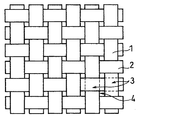
次に、平織の炭素繊維織布を例にとって、炭素繊維織布の織物組織を説明する。図1は平織の炭素繊維織布の平面図であり、等間隔で配列された縦糸1に直角方向に横糸2が等間隔で交錯している。炭素繊維織布の縦糸1および横糸2は、単独の糸からなる単糸である場合以外に、2本の糸からなる双糸など複数の糸からなる場合がある。従って、縦糸1あるいは横糸2の断面は必ずしも円形ではないので、本発明においては、縦糸の太さおよび横糸の太さは、便宜上、炭素繊維織布の平面図から見た縦糸の幅および横糸の幅を表すものとする。 Next, the fabric structure of the carbon fiber woven fabric will be described by taking a plain woven carbon fiber woven fabric as an example. FIG. 1 is a plan view of a plain-woven carbon fiber woven fabric, in which weft yarns 2 are intersected at equal intervals in a direction perpendicular to warp yarns 1 arranged at equal intervals. The warp yarn 1 and the weft yarn 2 of the carbon fiber woven fabric may be composed of a plurality of yarns such as a twin yarn composed of two yarns, in addition to a single yarn composed of a single yarn. Therefore, since the cross section of the warp 1 or the weft 2 is not necessarily circular, in the present invention, the thickness of the warp and the width of the weft are, for convenience, the width of the warp and the width of the weft as viewed from a plan view of the carbon fiber woven fabric. It shall represent the width.
本発明における炭素繊維織布では、縦糸1と横糸2が交わっている交錯部分3の面積に対して、縦糸1と横糸2のいずれもが存在しない隙間部分4の面積を1/1500〜1/5という比率で圧倒的に小さくすることにより、撥水層形成用塗料を炭素繊維織布に塗布した際に、隙間部分4からの優先的な塗料の染み込みが抑制され、均一な撥水層を形成できる。これにより、撥水能が触媒層に接する側の表面からガス流路側の表面にかけてなだらかな傾斜で減衰する特性を有するガス拡散層が得られる。このガス拡散層を備えたMEAを用いることにより、高加湿運転時においても、ガス拡散層中の細孔に水を取り込ませることなく、余剰水を円滑にガス流路に排出することができる。 In the carbon fiber woven fabric according to the present invention, the area of the gap portion 4 where neither the warp yarn 1 nor the weft yarn 2 is present is set to 1/1500 to 1/1 / the area of the intersecting portion 3 where the warp yarn 1 and the weft yarn 2 intersect. By predominantly reducing the ratio by a factor of 5, when the paint for forming a water-repellent layer is applied to a carbon fiber woven fabric, preferential penetration of the paint from the gap portion 4 is suppressed, and a uniform water-repellent layer is formed. Can be formed. As a result, a gas diffusion layer having the characteristic that the water repellency attenuates with a gentle slope from the surface in contact with the catalyst layer to the surface on the gas flow path side is obtained. By using the MEA having the gas diffusion layer, even during high humidification operation, excess water can be smoothly discharged to the gas flow path without taking water into the pores in the gas diffusion layer.
従来からの問題点として、複数のMEAを積層し、これを締結してPEFCを構成する際、構成部材間の接触抵抗を低くするために締結圧力を高めると構成部材にたわみが生じる。そのため、ガスがリークしない範囲内で締結圧力を低く抑える必要がある。締結圧力が低いと、触媒層とガス拡散層の界面に基材の凹凸に沿った隙間が生じて水が滞留し易く、余剰水がMEAの外部に排出されない。 As a conventional problem, when a plurality of MEAs are stacked and fastened to form a PEFC, if the fastening pressure is increased to reduce the contact resistance between the components, the components will bend. Therefore, it is necessary to keep the fastening pressure low within a range in which gas does not leak. If the fastening pressure is low, a gap is formed along the unevenness of the substrate at the interface between the catalyst layer and the gas diffusion layer, so that water tends to stay, and surplus water is not discharged to the outside of the MEA.
本発明により炭素繊維織布の交錯部分3の面積比率を多くすることで、表面の凸部と凹部の段差が少なくなり、表面が平滑化される。これにより上記の問題が解決される。即ち、本発明における炭素繊維織布は、厚みが大きい交錯部分3が厚みが小さい隙間部分4より5〜1500倍も多いために、表面の凹部と凸部の段差が小さくなっている。この炭素繊維織布を用いることで上記の触媒層とガス拡散層の界面での隙間の形成が抑止され、余剰水が滞留する問題が解消される。 By increasing the area ratio of the intersecting portion 3 of the carbon fiber woven fabric according to the present invention, the level difference between the convex portion and the concave portion on the surface is reduced, and the surface is smoothed. This solves the above problem. That is, in the carbon fiber woven fabric according to the present invention, since the intersecting portion 3 having a large thickness is 5 to 1500 times as large as the gap portion 4 having a small thickness, the step between the concave portion and the convex portion on the surface is small. By using this carbon fiber woven fabric, the formation of a gap at the interface between the catalyst layer and the gas diffusion layer is suppressed, and the problem of excess water remaining is eliminated.
以上のように、表面状態が平滑な炭素繊維織布に均一な撥水層が形成されたガス拡散層を備えた本発明によるMEAを用いたPEFCでは、特にガス拡散層の余剰水排出能力が必要となる高加湿運転において、高い性能を発揮することができる。 As described above, in the PEFC using the MEA according to the present invention provided with the gas diffusion layer in which the uniform water-repellent layer is formed on the carbon fiber woven fabric having a smooth surface state, the excess water discharge capacity of the gas diffusion layer is particularly high. In the required high humidification operation, high performance can be exhibited.
ガス拡散層基材としての炭素繊維織布において、交錯部分に対する隙間部分の面積比が1/5を超えると、表面の平滑性が不充分となり、さらに不均一な塗料の染み込みを充分に抑制することができなくなる。また、前記の面積比が1/1500未満の場合には、ガス拡散層内の空隙が不足して、ガス拡散能力および水分透過能力が不充分となる。 In the carbon fiber woven fabric as the gas diffusion layer base material, if the area ratio of the gap portion to the intersecting portion exceeds 1/5, the surface smoothness becomes insufficient, and the uneven paint penetration is sufficiently suppressed. You can't do that. When the area ratio is less than 1/1500, the voids in the gas diffusion layer are insufficient, and the gas diffusion capacity and the moisture permeability are insufficient.
本発明のMEAに用いる炭素繊維織布は、その厚みが0.05〜0.30mmの範囲にあることが好ましく、0.05〜0.20mmの範囲にあることがさらに好ましい。炭素繊維織布の厚みを小さくすることにより、炭素繊維織布の表面の凹部と凸部の段差をより小さくし、平滑化することができる。これにより、ガス拡散層と触媒層との接合部の水の滞留を一層効果的に防止することができ、高加湿運転でのフラッディング現象の発生を一層効果的に阻止できるMEAを提供することが可能となる。 The thickness of the carbon fiber woven fabric used for the MEA of the present invention is preferably in the range of 0.05 to 0.30 mm, and more preferably in the range of 0.05 to 0.20 mm. By reducing the thickness of the carbon fiber woven fabric, it is possible to further reduce the level difference between the concave portion and the convex portion on the surface of the carbon fiber woven fabric and to smooth the surface. Accordingly, it is possible to provide an MEA that can more effectively prevent water from staying at the junction between the gas diffusion layer and the catalyst layer, and can more effectively prevent the occurrence of a flooding phenomenon in a high humidification operation. It becomes possible.
炭素繊維織布を薄くするほどガス拡散層中の空隙体積が小さくなり、ガス拡散層中の水の滞留量が少くなるので、これを容易に排出することができる。しかし、0.05mmよりも薄い炭素繊維織布は、取り扱いが困難であったり、原料の炭素繊維糸の引張強度が不十分なため織布できない場合が多い。一方、0.30mmよりも厚い炭素繊維織布は、表面の凹部と凸部の段差が大きくなることにより、ガス拡散層と触媒層との接合部に水が滞留するという弊害が生じやすい。 The thinner the carbon fiber woven fabric, the smaller the void volume in the gas diffusion layer and the smaller the amount of water retained in the gas diffusion layer, so that it can be easily discharged. However, carbon fiber woven fabrics thinner than 0.05 mm are often difficult to handle or cannot be woven due to insufficient tensile strength of the raw carbon fiber yarns. On the other hand, in a carbon fiber woven fabric having a thickness of more than 0.30 mm, an adverse effect such that water stays at the joint between the gas diffusion layer and the catalyst layer is likely to occur due to a large step between the concave portion and the convex portion on the surface.
本発明のMEAに用いる炭素繊維織布は、その密度が0.32〜0.42g/ccの範囲にあることが好ましい。炭素繊維織布の繊維の密度を低く抑えることにより、燃料電池スタックを締結する時の圧力により炭素繊維織布が圧縮されて平滑化され易くなる。 The carbon fiber woven fabric used for the MEA of the present invention preferably has a density in the range of 0.32 to 0.42 g / cc. By suppressing the fiber density of the carbon fiber woven fabric to a low level, the pressure at the time of fastening the fuel cell stack causes the carbon fiber woven fabric to be easily compressed and smoothed.
このように、炭素繊維織布が圧縮されて平滑化されると、その表面の凹部と凸部の段差がより小さくなり、ガス拡散層と触媒層の接合部に水が滞留する隙間をなくすことができる。その結果、高加湿運転でのフラッディング現象の発生をより一層効果的に阻止できるMEAを提供することが可能となる。炭素繊維織布の密度は低いほど上記の効果は大きいが、炭素繊維織布の密度が0.32g/cc未満では炭素繊維織布の機械的強度が不十分なために、MEAを製造する際の取り扱いが困難となる。一方、炭素繊維織布の密度が0.42g/ccを超えると前記の締結時の圧力により炭素繊維織布が充分に平滑化されず、上記の効果を充分には得ることができない。 As described above, when the carbon fiber woven fabric is compressed and smoothed, the step between the concave portion and the convex portion on the surface becomes smaller, and the gap where water stays at the junction between the gas diffusion layer and the catalyst layer is eliminated. Can be. As a result, it is possible to provide an MEA that can more effectively prevent the occurrence of the flooding phenomenon in the high humidification operation. The lower the density of the carbon fiber woven fabric, the greater the above-mentioned effect. However, if the density of the carbon fiber woven fabric is less than 0.32 g / cc, the mechanical strength of the carbon fiber woven fabric is insufficient. Handling becomes difficult. On the other hand, if the density of the carbon fiber woven fabric exceeds 0.42 g / cc, the pressure at the time of fastening does not sufficiently smooth the carbon fiber woven fabric, and the above effects cannot be obtained sufficiently.
本発明のMEAに用いる炭素繊維織布は、その縦糸密度および横糸密度のいずれか一方が16〜45本/cmの範囲にあり、かつ、他方が12〜40本/cmの範囲にあることが好ましい。糸密度(単位長さあるいは幅当たりの炭素繊維織布の糸の本数)を高めることで、1本の糸あたりの太さが細くなるので、交錯部分の厚みを小さくすることが可能となり、炭素繊維織布の表面の凹部と凸部の段差を小さくできる。これにより、炭素繊維織布の表面が一層平滑になり、しかも均一な撥水層の形成が可能となる。 In the carbon fiber woven fabric used for the MEA of the present invention, one of the warp yarn density and the weft yarn density is in the range of 16 to 45 yarns / cm, and the other is in the range of 12 to 40 yarns / cm. preferable. By increasing the yarn density (the number of carbon fiber woven fabric yarns per unit length or width), the thickness of each yarn becomes thinner, so that the thickness of the intersecting portion can be reduced, and carbon The step between the concave portion and the convex portion on the surface of the fiber woven fabric can be reduced. Thereby, the surface of the carbon fiber woven fabric becomes smoother, and a uniform water-repellent layer can be formed.
また、糸密度を高めることで、炭素繊維織布の隙間部分を多数存在させ、かつ個々の隙間部分の面積を小さくすることができる。これにより、余剰水をガス拡散層を通して円滑にMEA外部に排出させるため、あるいはガス拡散層内で反応ガスを拡散させるために適した微細な空間を多数形成することができる。これらの効果により、高加湿運転での余剰水の排出が円滑に行われ、フラッディング現象の発生をより一層効果的に阻止できるMEAを提供することができる。 In addition, by increasing the yarn density, a large number of gap portions of the carbon fiber woven fabric can be present, and the area of each gap portion can be reduced. This makes it possible to form many fine spaces suitable for smoothly discharging excess water to the outside of the MEA through the gas diffusion layer or for diffusing the reaction gas in the gas diffusion layer. With these effects, it is possible to provide an MEA in which surplus water can be smoothly discharged in the high humidification operation, and the occurrence of the flooding phenomenon can be more effectively prevented.
炭素繊維織布の縦糸密度と横糸密度は高い方が上記の効果は顕著に得られるが、上記の好ましい密度を超える場合には、糸が細くなりすぎるため、炭素繊維織布の作製および炭素繊維織布の取り扱いが困難である。一方、糸密度が上記の好ましい密度より少ない場合には、糸が太くなりすぎるため、炭素繊維織布の表面の凹部と凸部の段差が大きくなる。この炭素繊維織布を用いてMEAを作製すると、触媒層とガス拡散層との接合部に水が滞留する隙間が生じやすい。 The higher the warp yarn density and the higher weft yarn density of the carbon fiber woven fabric, the more remarkable the above-mentioned effect is obtained.However, if the density exceeds the preferred density, the yarn becomes too thin. Difficulty handling woven fabric. On the other hand, when the yarn density is lower than the above preferable density, the yarn becomes too thick, so that the step between the concave portion and the convex portion on the surface of the carbon fiber woven fabric increases. When an MEA is manufactured using this carbon fiber woven fabric, a gap where water stays tends to be generated at a joint between the catalyst layer and the gas diffusion layer.
撥水層に含ませる撥水材としては、耐熱性、耐酸性、耐薬品性に優れていることから、ポリ4フッ化エチレン(PTFE)などのフッ素系樹脂が一般的に用いられるが、シリコーン系やその他の長期にわたる撥水性が確保できる撥水材を用いることもできる。撥水層は、集電体として機能するガス拡散層の片側に形成される層なので、導電性を有することが必要であるため、撥水層には導電性材料を含ませる必要がある。 As a water-repellent material contained in the water-repellent layer, a fluorine-based resin such as polytetrafluoroethylene (PTFE) is generally used because of its excellent heat resistance, acid resistance, and chemical resistance. It is also possible to use a system or other water-repellent material that can ensure long-term water repellency. Since the water-repellent layer is a layer formed on one side of the gas diffusion layer functioning as a current collector, the water-repellent layer needs to have conductivity. Therefore, the water-repellent layer needs to contain a conductive material.
導電性材料としては、耐酸性に優れていることから、カーボンが一般的に用いられ、その中でも撥水性が強いアセチレンブラックが主に用いられる。しかし、撥水性が強いカーボンは逆に塗料化が難しいため、撥水材との組合せによっては親水性カーボンであるケッチェンブラックなどが好ましい場合もある。その他の導電性材料として金属材料を用いることもできる。撥水層の一般的な形成方法は、上記の撥水材と導電性材料を水などの分散媒に分散させて調製した撥水層形成用塗料を直接に炭素繊維織布の片側に塗布する方法である。その塗布方法は、スプレー法、スピンコート、ドクターブレード、スクリーン印刷、コータ塗布、およびグラビア印刷などのいずれであってもよい。 As the conductive material, carbon is generally used because of its excellent acid resistance, and among them, acetylene black having strong water repellency is mainly used. However, since carbon having high water repellency is difficult to make into a paint, conversely, depending on the combination with a water repellent material, Ketjen black, which is hydrophilic carbon, may be preferable. A metal material can be used as another conductive material. A general method of forming a water-repellent layer is to apply a water-repellent layer-forming paint prepared by dispersing the above-described water-repellent material and a conductive material in a dispersion medium such as water directly to one side of a carbon fiber woven fabric. Is the way. The coating method may be any of spraying, spin coating, doctor blade, screen printing, coater coating, and gravure printing.
セパレータ板に形成されるガス流路としては、入口から出口に向かって複数の直線パスが一方向に平行に施されたストレートタイプ、および、単数もしくは複数のパスが蛇腹状に施されたサーペンタインタイプなどがある。ガス流路の形態は、さらにアノード側とカソード側のガスの流れ方向の相違により、直交型、対向型および並行型に分けられる。本発明は、上記のいずれのガス流路を有するPEFCにも有効に適用することができる。 As a gas passage formed in the separator plate, a straight type in which a plurality of straight paths are provided in parallel in one direction from an inlet to an outlet, and a serpentine type in which one or more paths are provided in a bellows shape, etc. There is. The form of the gas flow path is further classified into an orthogonal type, a facing type, and a parallel type according to the difference in the gas flow direction between the anode side and the cathode side. The present invention can be effectively applied to a PEFC having any of the above gas flow paths.
本発明の燃料電池の運転方法は、上記本発明によるMEAおよびその外側に接するガス流路を有する一対のセパレータ板を具備したPEFCの運転方法であって、燃料ガスの露点、酸化剤ガスの露点、およびMEAの運転時の温度を所定の温度範囲でコントロールして運転するものである。 The method for operating a fuel cell according to the present invention is a method for operating a PEFC including the MEA according to the present invention and a pair of separator plates having a gas flow path in contact with the outside of the MEA. , And the temperature of the MEA during operation is controlled within a predetermined temperature range.
本発明によるMEAは、前記のように表面が平滑な炭素繊維織布に撥水層形成用塗料の不均一な染み込みが無い均一な撥水層が形成されたガス拡散層を備えているので、PEFCの高加湿運転時に必要とされる余剰水の排出能力およびガス拡散能力を充分に備えている。従って、このMEAを備えたPEFCは、最も典型的な高加湿条件での運転、即ちアノードに供給する燃料ガスの露点温度、カソードに供給する酸化剤ガスの露点温度、およびMEAの運転時の温度が等しくなるようにコントロールされて運転される場合に、特に優れた性能を発揮することができる。その場合に燃料ガスの露点および酸化剤ガスの露点を、電解質膜−電極接合体の運転時の温度に対して5℃以内の範囲内で低い温度にコントロールして運転することにより、実質的には三者の温度を等しくした場合に準じた優れた性能を得ることができる。 Since the MEA according to the present invention includes the gas diffusion layer in which the uniform water-repellent layer is formed on the carbon fiber woven fabric having a smooth surface as described above without the non-uniform penetration of the coating material for forming the water-repellent layer, PEFC has sufficient discharge capacity and gas diffusion capacity required for high humidification operation of PEFC. Therefore, the PEFC equipped with the MEA is operated under the most typical high humidification conditions, that is, the dew point temperature of the fuel gas supplied to the anode, the dew point temperature of the oxidizing gas supplied to the cathode, and the temperature during the operation of the MEA. In particular, excellent performance can be exhibited when the vehicle is operated while being controlled to be equal to each other. In this case, by controlling the dew point of the fuel gas and the dew point of the oxidizing gas to a lower temperature within 5 ° C. with respect to the temperature at the time of operation of the electrolyte membrane-electrode assembly, the operation is substantially performed. Can obtain excellent performance according to the case where the temperatures of the three are equal.
次に、本発明を実施例により具体的に説明する。各実施例および各比較例においては、いずれも下記の方法で単電池を作製した。それらの単電池の代表図を図2に示す。各実施例および各比較例毎に定めた平織の炭素繊維織布の片面に撥水層形成用塗料をドクターブレードを用いて塗布した。撥水層形成用塗料は、アセチレンブラック(AB)と水を重量比1:4で混合し、これに界面活性剤を少量加えて混練した後、PTFE固形分とABの重量比が1:7になるようPTFEの分散液(ダイキン工業(株)製:D1)を添加して調製した。この塗料を片面に塗布した炭素繊維織布を約100℃で1時間乾燥し、さらに約270℃で1時間焼成して炭素繊維織布に撥水層が形成されたガス拡散層13を作製した。
Next, the present invention will be specifically described with reference to examples. In each of the examples and comparative examples, a unit cell was produced by the following method. FIG. 2 shows a representative diagram of these cells. A coating material for forming a water-repellent layer was applied to one surface of a plain-woven carbon fiber woven fabric determined for each example and each comparative example using a doctor blade. The coating material for forming a water-repellent layer was prepared by mixing acetylene black (AB) and water at a weight ratio of 1: 4, adding a small amount of a surfactant thereto and kneading the mixture, and then adjusting the weight ratio of PTFE solids to AB to 1: 7. The dispersion was prepared by adding a dispersion of PTFE (D1 manufactured by Daikin Industries, Ltd.). The carbon fiber woven fabric coated with this paint on one side was dried at about 100 ° C. for 1 hour, and further baked at about 270 ° C. for 1 hour to produce a
一方では、パーフルオロスルホン酸樹脂からなる高分子電解質膜11(米国デュポン社製:Nafion112)の両面に、周縁部を残して触媒層12を転写法により接合した。次いで、それぞれの触媒層12の外側に撥水層側が接するように、ガス拡散層13をそれぞれの触媒層12に接合してMEA15を作製した。高分子電解質膜11に転写した触媒層12は、触媒用ペーストを樹脂シートに塗布し乾燥して形成した。MEAの触媒層12の面積は25cm2とした。触媒用ペーストは、炭素微粉末(ライオン(株)製:ケッチェンブラックEC)に白金触媒を1:1の重量比で担持させた触媒100重量部と、エタノールに分散させたパーフルオロスルホン酸樹脂80重量部を混合し、この混合物を水とエタノールの混合分散媒に投入し、攪拌して調製した。
On the other hand, the
次いで、このMEA15の周縁部の高分子電解質膜11の両面にガスケット18を配置し、これを100℃で5分間のホットプレスを行うことにより接合した。この接合体をその両面からカソード側およびアノード側のカーボン製セパレータ板17で挟み、セパレータ板17に形成されたリブ19に約7kgf/cm2の面圧力が加わるように締結し、PEFCの単電池を作製した。カソード側およびアノード側のセパレータ板17には、それぞれ断面積1.0cm2の3本の溝からなるサーペンタインタイプのガス流路16を備えている。
Next,
各実施例および各比較例において使用した炭素繊維織布の縦糸および横糸の太さは、15kVの加速電圧で撮った倍率100倍のSEM写真から計測した。1cm当たりの糸の本数(縦糸密度および横糸密度)は、25倍の顕微鏡写真から5cm当たりの糸の本数を計測し、その計測値から1cm当たりの平均値を算出した。目付け重量は炭素繊維織布を12cm×12cmに打ち抜き、その重量の測定値から算出し、密度は算出した目付け重量と炭素繊維織布の厚みから求めた。 The thickness of the warp and the weft of the carbon fiber woven fabric used in each Example and each Comparative Example was measured from a SEM photograph at a magnification of 100 times taken at an acceleration voltage of 15 kV. The number of yarns per 1 cm (warp yarn density and weft yarn density) was obtained by measuring the number of yarns per 5 cm from a 25-fold micrograph and calculating the average value per 1 cm from the measured value. The basis weight was obtained by punching a carbon fiber woven fabric into a size of 12 cm × 12 cm, and was calculated from the measured value of the weight. The density was determined from the calculated basis weight and the thickness of the carbon fiber woven fabric.
《実施例1》
双糸からなる太さ0.480mmの縦糸と、双糸からなる太さ0.480mmの横糸により織布された炭素繊維織布をガス拡散層の基材として用いた単電池を作製した。この炭素繊維織布の縦糸密度は20.1本/cm、横糸密度は18.1本/cm、目付け重量は110g/m2、厚みは0.28mm、密度は0.393g/ccであった。
<< Example 1 >>
A single cell was produced using a carbon fiber woven fabric woven with a warp yarn having a thickness of 0.480 mm made of twin yarn and a weft yarn having a thickness of 0.480 mm made of twin yarn as a base material of the gas diffusion layer. The warp yarn density of this carbon fiber woven fabric was 20.1 yarns / cm, the weft yarn density was 18.1 yarns / cm, the basis weight was 110 g / m 2 , the thickness was 0.28 mm, and the density was 0.393 g / cc. .
《実施例2》
双糸からなる太さ0.450mmの縦糸と、単糸からなる太さ0.450mmの横糸により織布された炭素繊維織布をガス拡散層の基材として用いた単電池を作製した。この炭素繊維織布の縦糸密度は17.7本/cm、横糸密度は15.4本/cm、目付け重量は105g/m2、厚みは0.29mm、密度は0.362g/ccであった。
<< Example 2 >>
A single cell was produced using a carbon fiber woven fabric woven with a warp yarn having a thickness of 0.450 mm made of a twin yarn and a weft yarn having a thickness of 0.450 mm made of a single yarn as a base material of a gas diffusion layer. The warp yarn density of this carbon fiber woven fabric was 17.7 yarns / cm, the weft yarn density was 15.4 yarns / cm, the basis weight was 105 g / m 2 , the thickness was 0.29 mm, and the density was 0.362 g / cc. .
《実施例3》
双糸からなる太さ0.445mmの縦糸と、双糸からなる太さ0.445mmの横糸により織布された炭素繊維織布をガス拡散層の基材として用いた単電池を作製した。この炭素繊維織布の縦糸密度は15.7本/cm、横糸密度は15.4本/cm、目付け重量は80g/m2、厚みは0.20mm、密度は0.400g/ccであった。
<< Example 3 >>
A single cell was manufactured using a carbon fiber woven fabric woven with a warp yarn having a thickness of 0.445 mm made of twin yarn and a weft yarn having a thickness of 0.445 mm formed of twin yarn as a base material of the gas diffusion layer. The warp yarn density of this carbon fiber woven fabric was 15.7 yarns / cm, the weft yarn density was 15.4 yarns / cm, the basis weight was 80 g / m 2 , the thickness was 0.20 mm, and the density was 0.400 g / cc. .
《実施例4》
双糸からなる太さ0.360mmの縦糸と、双糸からなる太さ0.360mmの横糸により織布された炭素繊維織布をガス拡散層の基材として用いた単電池を作製した。この炭素繊維織布の縦糸密度は23.6本/cm、横糸密度は22.0本/cm、目付け重量は115g/m2、厚みは0.29mm、密度は0.397g/ccであった。
<< Example 4 >>
A single cell was produced using a carbon fiber woven fabric woven with a 0.360 mm thick warp made of twin yarns and a 0.360 mm thick weft made of twin yarns as the base material of the gas diffusion layer. The warp yarn density of this carbon fiber woven fabric was 23.6 yarns / cm, the weft yarn density was 22.0 yarns / cm, the basis weight was 115 g / m 2 , the thickness was 0.29 mm, and the density was 0.397 g / cc. .
《実施例5》
双糸からなる太さ0.465mmの縦糸と、双糸からなる太さ0.470mmの横糸により織布された炭素繊維織布をガス拡散層の基材として用いた単電池を作製した。この炭素繊維織布の縦糸密度は21.3本/cm、横糸密度は20.1本/cm、目付け重量は125g/m2、厚みは0.30mm、密度は0.417g/ccであった。
<< Example 5 >>
A single cell was produced using a carbon fiber woven fabric woven with a warp yarn having a thickness of 0.465 mm made of twin yarn and a weft yarn having a thickness of 0.470 mm made of twin yarn as a base material of the gas diffusion layer. The warp yarn density of this carbon fiber woven fabric was 21.3 yarns / cm, the weft yarn density was 20.1 yarns / cm, the basis weight was 125 g / m 2 , the thickness was 0.30 mm, and the density was 0.417 g / cc. .
《比較例1》
双糸からなる太さ0.420mmの縦糸と、双糸からなる太さ0.420mmの横糸により織布された炭素繊維織布をガス拡散層の基材として用いた単電池を作製した。この炭素繊維織布の縦糸密度は15.7本/cm、横糸密度は15.7本/cm、目付け重量は114g/m2、厚みは0.30mm、密度は0.380g/ccであった。
<< Comparative Example 1 >>
A unit cell was produced using a carbon fiber woven fabric woven with a warp yarn having a thickness of 0.420 mm made of twin yarn and a weft yarn having a thickness of 0.420 mm made of twin yarn as a base material of the gas diffusion layer. The warp yarn density of this carbon fiber woven fabric was 15.7 yarns / cm, the weft yarn density was 15.7 yarns / cm, the basis weight was 114 g / m 2 , the thickness was 0.30 mm, and the density was 0.380 g / cc. .
《比較例2》
双糸からなる太さ0.470mmの縦糸と、双糸からなる太さ0.470mmの横糸により織布された炭素繊維織布をガス拡散層の基材として用いた単電池を作製した。この炭素繊維織布の縦糸密度は21.3本/cm、横糸密度は17.3本/cm、目付け重量は100g/m2、厚みは0.27mm、密度は0.370g/ccであった。
<< Comparative Example 2 >>
A single cell was produced using a carbon fiber woven fabric woven with a warp yarn having a thickness of 0.470 mm made of twin yarn and a weft yarn having a thickness of 0.470 mm made of twin yarn as a base material of the gas diffusion layer. The warp yarn density of this carbon fiber woven fabric was 21.3 yarns / cm, the weft yarn density was 17.3 yarns / cm, the basis weight was 100 g / m 2 , the thickness was 0.27 mm, and the density was 0.370 g / cc. .
上記のように織り方を変えて作製した種々の炭素繊維織布を使用した実施例1〜5、比較例1および比較例2の各単電池を用いて下記の手順で各種の電池試験を行った。まず、アノードに露点が70℃となるように加温・加湿した燃料ガス(水素ガス)を、カソードに露点が70℃となるように加温・加湿した酸化剤ガス(空気)をそれぞれ供給し、MEAの運転時の温度70℃、水素ガス利用率70%、および空気利用率40%という条件下で電池試験1を実施した。次いで、空気利用率を40%から80%に変更し、電池試験2を実施した。 Various battery tests were performed by the following procedure using each unit cell of Examples 1 to 5 and Comparative Examples 1 and 2 using various carbon fiber woven fabrics produced by changing the weaving method as described above. Was. First, a fuel gas (hydrogen gas) heated and humidified so that the dew point becomes 70 ° C. is supplied to the anode, and an oxidant gas (air) heated and humidified so that the dew point becomes 70 ° C. is supplied to the cathode. The battery test 1 was performed under the conditions of a temperature of 70 ° C., a hydrogen gas utilization rate of 70%, and an air utilization rate of 40% during the operation of the MEA. Next, the battery test 2 was performed by changing the air utilization rate from 40% to 80%.
次いで、アノードに供給する水素ガスの露点67℃、カソードに供給する空気の露点70℃、MEAの運転時の温度70℃、燃料ガス利用率70%、および空気利用率40%という条件下で電池試験3を実施した。さらに、空気利用率を40%から80%に変更し、電池試験4を実施した。 Then, under the conditions that the dew point of hydrogen gas supplied to the anode is 67 ° C., the dew point of air supplied to the cathode is 70 ° C., the temperature during MEA operation is 70 ° C., the fuel gas utilization rate is 70%, and the air utilization rate is 40%. Test 3 was performed. Further, the battery test 4 was performed by changing the air utilization rate from 40% to 80%.
次いで、アノードに供給する水素ガスの露点67℃、カソードに供給する空気の露点65℃、MEAの運転時の温度70℃、燃料ガス利用率70%、および空気利用率40%という条件下で電池試験5を実施した。さらに、空気利用率を40%から80%に変更し、電池試験6を実施した。 Then, under the conditions that the dew point of the hydrogen gas supplied to the anode is 67 ° C., the dew point of the air supplied to the cathode is 65 ° C., the temperature during the operation of the MEA is 70 ° C., the fuel gas utilization rate is 70%, and the air utilization rate is 40%. Test 5 was performed. Further, the battery test 6 was performed with the air utilization rate changed from 40% to 80%.
次いで、アノードに供給する水素ガスの露点65℃、カソードに供給する空気の露点65℃、MEAの運転時の温度70℃、燃料ガス利用率70%、および空気利用率40%という条件下で電池試験7を実施した。さらに、空気利用率を40%から80%に変更し、電池試験8を実施した。 Next, under conditions of a hydrogen gas dew point of 65 ° C. supplied to the anode, an air dew point of 65 ° C. supplied to the cathode, a temperature of 70 ° C. during operation of the MEA, a fuel gas utilization rate of 70%, and an air utilization rate of 40%. Test 7 was performed. Further, the battery test 8 was performed while changing the air utilization rate from 40% to 80%.
次いで、アノードに供給する水素ガスの露点65℃、カソードに供給する空気の露点55℃、MEAの運転時の温度70℃、燃料ガス利用率70%、および空気利用率40%という条件下で電池試験9を実施した。さらに、空気利用率を40%から80%に変更し、電池試験10を実施した。運転時の電流密度は上記の電池試験1〜10のいずれにおいても0.3A/cm2とした。 Next, under conditions of a dew point of hydrogen gas supplied to the anode of 65 ° C., a dew point of air supplied to the cathode of 55 ° C., a temperature during operation of the MEA of 70 ° C., a fuel gas utilization rate of 70%, and an air utilization rate of 40%. Test 9 was performed. Further, the battery test 10 was performed with the air utilization rate changed from 40% to 80%. The current density during operation was 0.3 A / cm 2 in any of the above battery tests 1 to 10.
表1に実施例1〜5、比較例1および比較例2で使用した炭素繊維織布の交錯部分と隙間部分の面積比(10/W−Y)(10/Z−X)/XYと電池試験1〜10でのそれぞれの作動電圧値を示す。表1においては、便宜上、前記の面積比を単に面積比で表す。 Table 1 shows the area ratio (10 / WY) (10 / ZX) / XY of the intersecting portion and the gap portion of the carbon fiber woven fabric used in Examples 1 to 5, Comparative Example 1 and Comparative Example 2, and the battery. The respective operating voltage values in Tests 1 to 10 are shown. In Table 1, the above-mentioned area ratio is simply represented by the area ratio for convenience.

反応ガスの加湿条件とMEAの運転時の温度を同一条件とし、空気の利用率を40%から80%に変更した場合の作動電圧の差(A−B,C−D、E−F、G−HおよびI−J)が正の値であることは、利用率40%での作動電圧が利用率80%での作動電圧よりも高いことであり、その値が小さいことは、カソードに供給する空気の利用率(流速)による電圧変動が小さく、運転時に安定した出力が得られることを示している。逆に前記の作動電圧の差が大きいことは、空気の流速により作動電圧が変動し易いことを示しており、同時に、空気の流速を下げればフラッディング気味の運転状態となり易いことを示している。また、前記の作動電圧の差が負の値であることは、流速を下げれば電圧値が上がることから、流速を上げた場合に若干乾燥気味の運転になることを示している。 The operating voltage differences (AB, CD, EF, G) when the humidifying condition of the reaction gas and the temperature during the operation of the MEA are the same and the air utilization rate is changed from 40% to 80%. -H and IJ) are positive values when the operating voltage at a utilization of 40% is higher than the operating voltage at a utilization of 80%, and when the values are small, it means that the supply voltage to the cathode is low. This indicates that the voltage fluctuation due to the utilization rate (flow velocity) of the generated air is small, and that a stable output can be obtained during operation. Conversely, a large difference in the operating voltage indicates that the operating voltage is likely to fluctuate depending on the flow rate of the air, and at the same time indicates that the operating state tends to be slightly flooding if the flow rate of the air is reduced. Further, the fact that the difference between the operating voltages is a negative value indicates that when the flow rate is decreased, the voltage value is increased, so that when the flow rate is increased, the operation becomes slightly dry.
表1から分かる通り、面積比(10/W−Y)(10/Z−X)/XYが1/1500から1/5の範囲にある炭素繊維織布を用いた実施例1〜5の単電池については、高加湿運転での余剰水の排出が円滑に行われるため、電池試験1〜8のいずれにおいても比較例1および2の単電池よりも高い作動電圧を示している。 As can be seen from Table 1, the area ratios (10 / WY) (10 / ZX) / XY of Examples 1 to 5 using carbon fiber woven fabrics having a range of 1/1500 to 1/5 were used. Regarding the battery, since the surplus water was discharged smoothly in the high humidification operation, the operating voltage was higher than that of the unit cells of Comparative Examples 1 and 2 in all of Battery Tests 1 to 8.
一方、炭素繊維織布の面積比が上記の範囲外にある炭素繊維織布を用いた比較例1および比較例2の単電池は、電池試験1〜6のいずれにおいても実施例よりも作動電圧が低い上に、空気の利用率(流速)の差による作動電圧の差(A−B、C−DおよびE−F)も大きい。これは、カソードで生成される水が円滑に排出されず、フラッディングを引き起こしたことによるものと考えられる。 On the other hand, the cells of Comparative Examples 1 and 2 using the carbon fiber woven fabric in which the area ratio of the carbon fiber woven fabric was out of the above range were lower in the operating voltage than in the Examples in any of the battery tests 1 to 6. In addition, the differences in the operating voltages (AB, CD, and EF) due to the differences in the air utilization rate (flow rate) are large. This is considered to be because the water generated at the cathode was not discharged smoothly and caused flooding.
即ち、比較例1では、炭素繊維織布の隙間部分が多過ぎるため、均一な撥水層が形成されず、さらに表面の凹凸部の段差が大きいために、余剰水が円滑に排出されなかったものと考えられる。逆に、比較例2では、炭素繊維織布の隙間部分が少ないためにガス拡散層を余剰水が透過し難くかったために、余剰水が円滑に排出されなかったものと考えられる。 That is, in Comparative Example 1, a uniform water-repellent layer was not formed because the gap portion of the carbon fiber woven fabric was too large, and excess water was not discharged smoothly due to a large step of the uneven portion on the surface. It is considered. Conversely, in Comparative Example 2, it is considered that the surplus water was not discharged smoothly because the surplus water did not easily permeate the gas diffusion layer due to the small gap portion of the carbon fiber woven fabric.
電池試験9および10では、実施例1〜5および比較例1のいずれにおいても、電池試験1〜8での作動電圧よりも低い作動電圧を示している。さらに、これらの単電池における作動電圧の差(I−J)が負の値ないしはゼロであることから、露点55℃という比較的低湿度の空気をカソードに供給した場合には、若干乾燥気味の運転になることが分かる。一方、比較例2では、ガス拡散層を水が透過し難くいために、電池試験9および10においても、乾燥気味の運転とはならず、作動電圧の差(I−J)は正の値を示している。 In Battery Tests 9 and 10, in each of Examples 1 to 5 and Comparative Example 1, an operating voltage lower than the operating voltage in Battery Tests 1 to 8 was shown. Furthermore, since the difference (IJ) between the operating voltages of these cells is a negative value or zero, when air having a relatively low dew point of 55 ° C. is supplied to the cathode, the air becomes slightly dry. It turns out that it becomes driving. On the other hand, in Comparative Example 2, since it is difficult for water to permeate through the gas diffusion layer, even in Battery Tests 9 and 10, the operation was not slightly dry, and the operating voltage difference (I-J) had a positive value. Is shown.
本発明に係る電解質膜−電極接合体は、高分子電解質型燃料電池に好適に用いることができる。 The electrolyte membrane-electrode assembly according to the present invention can be suitably used for a polymer electrolyte fuel cell.
1 縦糸
2 横糸
3 縦糸と横糸の交わっている部分(交錯部分)
4 縦糸と横糸のいずれも存在しない隙間部分(隙間部分)
11 高分子電解質膜
12 触媒層
13 ガス拡散層
15 MEA
16 ガス流路
17 セパレータ板
18 ガスケット
19 リブ
1 Warp 2 Weft 3 Intersection of warp and weft (intersection)
4 Gap part where neither warp nor weft exists (gap part)
16
Claims (6)
前記ガス拡散層の基材が、電子伝導性炭素繊維からなる縦糸および横糸で織った炭素繊維織布であり、前記縦糸および横糸の交点間に開口が形成されていることを特徴とする燃料電池用電解質膜−電極接合体。 An electrolyte membrane-electrode comprising a polymer electrolyte membrane and a pair of electrodes sandwiching the polymer electrolyte membrane, wherein the electrode comprises a catalyst layer in contact with the polymer electrolyte membrane and a gas diffusion layer having a water-repellent layer in contact with the catalyst layer. A conjugate,
A fuel cell, wherein the base material of the gas diffusion layer is a carbon fiber woven fabric woven with warp yarns and weft yarns made of electron conductive carbon fiber, and an opening is formed between intersections of the warp yarns and the weft yarns. Electrolyte membrane-electrode assembly for use.
1/1500≦(10/W−Y)(10/Z−X)/XY≦1/5
の関係を満たす請求項1記載の燃料電池用電解質膜−電極接合体。 When the warp density of the carbon fiber woven fabric is Z yarns / cm, the weft yarn density is W yarns / cm, the warp yarn thickness is X mm, and the weft yarn thickness is Y mm,
1/1500 ≦ (10 / W−Y) (10 / Z−X) / XY ≦ 1/5
The fuel cell electrolyte membrane-electrode assembly according to claim 1, which satisfies the following relationship:
前記燃料ガスの露点および前記酸化剤ガスの露点を、前記電解質膜−電極接合体の運転時の温度に対して同一温度あるいは5℃以内の範囲内で低い温度にコントロールして運転することを特徴とする燃料電池の運転方法。 A fuel cell comprising the electrolyte membrane-electrode assembly for a fuel cell according to any one of claims 1 to 5, supplying a humidified fuel gas to an anode, and supplying a humidified oxidant gas to a cathode to generate power. Driving method,
The fuel cell and the oxidizing gas are controlled such that the dew point of the fuel gas and the dew point of the oxidizing gas are controlled to the same temperature or a lower temperature within a range of 5 ° C. with respect to the temperature at the time of operation of the electrolyte membrane-electrode assembly. Operating method of the fuel cell.
Priority Applications (1)
| Application Number | Priority Date | Filing Date | Title |
|---|---|---|---|
| JP2003409494A JP2004207231A (en) | 2002-12-11 | 2003-12-08 | Electrolyte membrane-electrode junction body for fuel cell and fuel cell operating method using it |
Applications Claiming Priority (2)
| Application Number | Priority Date | Filing Date | Title |
|---|---|---|---|
| JP2002359314 | 2002-12-11 | ||
| JP2003409494A JP2004207231A (en) | 2002-12-11 | 2003-12-08 | Electrolyte membrane-electrode junction body for fuel cell and fuel cell operating method using it |
Publications (2)
| Publication Number | Publication Date |
|---|---|
| JP2004207231A true JP2004207231A (en) | 2004-07-22 |
| JP2004207231A5 JP2004207231A5 (en) | 2006-10-26 |
Family
ID=32828571
Family Applications (1)
| Application Number | Title | Priority Date | Filing Date |
|---|---|---|---|
| JP2003409494A Pending JP2004207231A (en) | 2002-12-11 | 2003-12-08 | Electrolyte membrane-electrode junction body for fuel cell and fuel cell operating method using it |
Country Status (1)
| Country | Link |
|---|---|
| JP (1) | JP2004207231A (en) |
Cited By (10)
| Publication number | Priority date | Publication date | Assignee | Title |
|---|---|---|---|---|
| WO2006075681A1 (en) * | 2005-01-14 | 2006-07-20 | Matsushita Electric Industrial Co., Ltd. | Stack for fuel cell, and fuel cell |
| KR100742739B1 (en) | 2005-07-15 | 2007-07-25 | 경상대학교산학협력단 | Thread-type flexible battery |
| JP2009117354A (en) * | 2007-11-02 | 2009-05-28 | Qinghua Univ | Membrane-electrode assembly for fuel cell and its manufacturing method |
| WO2012002769A3 (en) * | 2010-07-02 | 2012-05-03 | 주식회사 샤인 | Electrode assembly comprising fiber-shaped structures |
| WO2012023774A3 (en) * | 2010-08-14 | 2012-05-03 | 주식회사 샤인 | Electrode assembly having fiber-shaped structures, and battery including same |
| JP2014063730A (en) * | 2012-08-31 | 2014-04-10 | Mitsubishi Rayon Co Ltd | Porous carbon electrode and method for manufacturing the same |
| US8859165B2 (en) | 2008-07-25 | 2014-10-14 | Tsinghua University | Membrane electrode assembly and fuel cell using the same |
| US8951697B2 (en) | 2008-12-17 | 2015-02-10 | Tsinghua University | Membrane electrode assembly and fuel cell using the same |
| US9077012B2 (en) | 2008-12-17 | 2015-07-07 | Tsinghua University | Membrane electrode assembly and biofuel cell using the same |
| US9077042B2 (en) | 2008-07-25 | 2015-07-07 | Tsinghua University | Membrane electrode assembly and biofuel cell using the same |
Citations (13)
| Publication number | Priority date | Publication date | Assignee | Title |
|---|---|---|---|---|
| JPS5696458A (en) * | 1979-09-27 | 1981-08-04 | Prototech Co | Electric catalyst gas diffusing electrode with thin carbon cloth as support* method therefor and electrochemical battery including same electrode |
| JPH07169469A (en) * | 1993-12-16 | 1995-07-04 | Toyota Motor Corp | Electrode |
| JP2000058073A (en) * | 1998-08-11 | 2000-02-25 | Toyota Central Res & Dev Lab Inc | Fuel cell |
| JP2000299113A (en) * | 1999-02-10 | 2000-10-24 | Toray Ind Inc | Conductive sheet and electrode base material for fuel cell using it |
| JP2001226855A (en) * | 2000-02-10 | 2001-08-21 | Mitsubishi Chemicals Corp | Woven fabric of pitch-based carbon fiber |
| JP2001345108A (en) * | 2000-05-31 | 2001-12-14 | Matsushita Electric Ind Co Ltd | Gas diffusion layer, manufacturing method, electrode for fuel cell, and fuel cell |
| WO2002042534A1 (en) * | 2000-11-24 | 2002-05-30 | Toho Tenax Co., Ltd. | Carbon fiber sheet and method for producing the same |
| JP2002324557A (en) * | 2001-04-27 | 2002-11-08 | Mitsubishi Electric Corp | Solid polymer fuel cell |
| JP2002327355A (en) * | 2001-02-28 | 2002-11-15 | Mitsubishi Chemicals Corp | Conductive carbonaceous fiber sheet and solid polymer fuel cell |
| JP2002348743A (en) * | 2001-05-29 | 2002-12-04 | Toho Tenax Co Ltd | Structural material of woven fabric made of flat carbon fiber-spun yarn |
| JP2003163009A (en) * | 2001-11-27 | 2003-06-06 | Asahi Glass Co Ltd | Solid polymer fuel battery |
| JP2003282090A (en) * | 2002-03-26 | 2003-10-03 | Matsushita Electric Ind Co Ltd | Junction of electrolyte membrane and electrode, production process thereof and fuel cell |
| JP2003336145A (en) * | 2002-03-13 | 2003-11-28 | Mitsubishi Chemicals Corp | Conductive carbonaceous fiber woven fabric and solid polymer fuel cell using the same |
-
2003
- 2003-12-08 JP JP2003409494A patent/JP2004207231A/en active Pending
Patent Citations (13)
| Publication number | Priority date | Publication date | Assignee | Title |
|---|---|---|---|---|
| JPS5696458A (en) * | 1979-09-27 | 1981-08-04 | Prototech Co | Electric catalyst gas diffusing electrode with thin carbon cloth as support* method therefor and electrochemical battery including same electrode |
| JPH07169469A (en) * | 1993-12-16 | 1995-07-04 | Toyota Motor Corp | Electrode |
| JP2000058073A (en) * | 1998-08-11 | 2000-02-25 | Toyota Central Res & Dev Lab Inc | Fuel cell |
| JP2000299113A (en) * | 1999-02-10 | 2000-10-24 | Toray Ind Inc | Conductive sheet and electrode base material for fuel cell using it |
| JP2001226855A (en) * | 2000-02-10 | 2001-08-21 | Mitsubishi Chemicals Corp | Woven fabric of pitch-based carbon fiber |
| JP2001345108A (en) * | 2000-05-31 | 2001-12-14 | Matsushita Electric Ind Co Ltd | Gas diffusion layer, manufacturing method, electrode for fuel cell, and fuel cell |
| WO2002042534A1 (en) * | 2000-11-24 | 2002-05-30 | Toho Tenax Co., Ltd. | Carbon fiber sheet and method for producing the same |
| JP2002327355A (en) * | 2001-02-28 | 2002-11-15 | Mitsubishi Chemicals Corp | Conductive carbonaceous fiber sheet and solid polymer fuel cell |
| JP2002324557A (en) * | 2001-04-27 | 2002-11-08 | Mitsubishi Electric Corp | Solid polymer fuel cell |
| JP2002348743A (en) * | 2001-05-29 | 2002-12-04 | Toho Tenax Co Ltd | Structural material of woven fabric made of flat carbon fiber-spun yarn |
| JP2003163009A (en) * | 2001-11-27 | 2003-06-06 | Asahi Glass Co Ltd | Solid polymer fuel battery |
| JP2003336145A (en) * | 2002-03-13 | 2003-11-28 | Mitsubishi Chemicals Corp | Conductive carbonaceous fiber woven fabric and solid polymer fuel cell using the same |
| JP2003282090A (en) * | 2002-03-26 | 2003-10-03 | Matsushita Electric Ind Co Ltd | Junction of electrolyte membrane and electrode, production process thereof and fuel cell |
Cited By (14)
| Publication number | Priority date | Publication date | Assignee | Title |
|---|---|---|---|---|
| US7632589B2 (en) | 2005-01-14 | 2009-12-15 | Panasonic Corporation | Fuel-cell stack and fuel cell |
| WO2006075681A1 (en) * | 2005-01-14 | 2006-07-20 | Matsushita Electric Industrial Co., Ltd. | Stack for fuel cell, and fuel cell |
| KR100742739B1 (en) | 2005-07-15 | 2007-07-25 | 경상대학교산학협력단 | Thread-type flexible battery |
| JP2009117354A (en) * | 2007-11-02 | 2009-05-28 | Qinghua Univ | Membrane-electrode assembly for fuel cell and its manufacturing method |
| US9077042B2 (en) | 2008-07-25 | 2015-07-07 | Tsinghua University | Membrane electrode assembly and biofuel cell using the same |
| US8859165B2 (en) | 2008-07-25 | 2014-10-14 | Tsinghua University | Membrane electrode assembly and fuel cell using the same |
| US8951697B2 (en) | 2008-12-17 | 2015-02-10 | Tsinghua University | Membrane electrode assembly and fuel cell using the same |
| US9077012B2 (en) | 2008-12-17 | 2015-07-07 | Tsinghua University | Membrane electrode assembly and biofuel cell using the same |
| WO2012002769A3 (en) * | 2010-07-02 | 2012-05-03 | 주식회사 샤인 | Electrode assembly comprising fiber-shaped structures |
| US9997787B2 (en) | 2010-07-02 | 2018-06-12 | Jenax Inc. | Electrode assembly comprising fiber-shaped structures |
| US9472803B2 (en) | 2010-07-02 | 2016-10-18 | Jenax Inc. | Electrode assembly comprising fiber-shaped structures |
| US9059469B2 (en) | 2010-08-14 | 2015-06-16 | Shine Co., Ltd. | Electrode assembly having fiber-shaped structures, and battery including same |
| WO2012023774A3 (en) * | 2010-08-14 | 2012-05-03 | 주식회사 샤인 | Electrode assembly having fiber-shaped structures, and battery including same |
| JP2014063730A (en) * | 2012-08-31 | 2014-04-10 | Mitsubishi Rayon Co Ltd | Porous carbon electrode and method for manufacturing the same |
Similar Documents
| Publication | Publication Date | Title |
|---|---|---|
| CA2571753C (en) | Gas diffusion electrode and solid-state high-molecular electrolyte type fuel cell | |
| JP4326179B2 (en) | Polymer electrolyte fuel cell | |
| KR100513183B1 (en) | Fuel cell | |
| JP4051080B2 (en) | Gas diffusion layer and fuel cell using the same | |
| CA2480342C (en) | Electrolyte membrane-electrode assembly, fuel cell using the same and production method thereof | |
| KR100474941B1 (en) | Gas diffusion electrode and fuel cell using this | |
| US7470483B2 (en) | Electrolyte membrane-electrode assembly for fuel cell and operation method of fuel cell using the same | |
| JP7304524B2 (en) | Fuel cell cathode catalyst layer and fuel cell | |
| JP2004207231A (en) | Electrolyte membrane-electrode junction body for fuel cell and fuel cell operating method using it | |
| JP2004146226A (en) | Fuel cell | |
| WO2002091503A1 (en) | Electrode for fuel cell and method of manufacturing the electrode | |
| JP4880131B2 (en) | Gas diffusion electrode and fuel cell using the same | |
| JP2009129599A (en) | Membrane electrode stack and fuel cell including the same | |
| CN114695903A (en) | Gas diffusion layer, membrane electrode assembly, and fuel cell | |
| JP2010146765A (en) | Assembly for fuel cell, fuel cell, and manufacturing method of them | |
| JP2009252442A (en) | Fuel cell | |
| JP2005158722A (en) | Fuel cell and fuel cell system |
Legal Events
| Date | Code | Title | Description |
|---|---|---|---|
| A521 | Written amendment |
Free format text: JAPANESE INTERMEDIATE CODE: A523 Effective date: 20060908 |
|
| A621 | Written request for application examination |
Free format text: JAPANESE INTERMEDIATE CODE: A621 Effective date: 20060908 |
|
| A977 | Report on retrieval |
Free format text: JAPANESE INTERMEDIATE CODE: A971007 Effective date: 20090227 |
|
| A131 | Notification of reasons for refusal |
Free format text: JAPANESE INTERMEDIATE CODE: A131 Effective date: 20090319 |
|
| A521 | Written amendment |
Free format text: JAPANESE INTERMEDIATE CODE: A523 Effective date: 20090518 |
|
| A02 | Decision of refusal |
Free format text: JAPANESE INTERMEDIATE CODE: A02 Effective date: 20090709 |