JP2004201290A - Image processing method, image processing device, image processing program, and record medium - Google Patents
Image processing method, image processing device, image processing program, and record medium Download PDFInfo
- Publication number
- JP2004201290A JP2004201290A JP2003391197A JP2003391197A JP2004201290A JP 2004201290 A JP2004201290 A JP 2004201290A JP 2003391197 A JP2003391197 A JP 2003391197A JP 2003391197 A JP2003391197 A JP 2003391197A JP 2004201290 A JP2004201290 A JP 2004201290A
- Authority
- JP
- Japan
- Prior art keywords
- blur
- image
- image processing
- dct coefficients
- blur index
- Prior art date
- Legal status (The legal status is an assumption and is not a legal conclusion. Google has not performed a legal analysis and makes no representation as to the accuracy of the status listed.)
- Granted
Links
- 238000012545 processing Methods 0.000 title claims abstract description 104
- 238000003672 processing method Methods 0.000 title claims abstract description 67
- 238000004364 calculation method Methods 0.000 claims abstract description 9
- 238000006243 chemical reaction Methods 0.000 claims description 6
- 230000003044 adaptive effect Effects 0.000 abstract description 2
- 238000003491 array Methods 0.000 abstract description 2
- 230000006872 improvement Effects 0.000 abstract description 2
- 238000000034 method Methods 0.000 description 34
- 108010076504 Protein Sorting Signals Proteins 0.000 description 14
- 230000006870 function Effects 0.000 description 14
- 230000009467 reduction Effects 0.000 description 12
- 230000000694 effects Effects 0.000 description 8
- 238000001228 spectrum Methods 0.000 description 8
- 238000004891 communication Methods 0.000 description 7
- 238000012937 correction Methods 0.000 description 7
- 230000008569 process Effects 0.000 description 7
- 238000013507 mapping Methods 0.000 description 6
- 238000001514 detection method Methods 0.000 description 4
- 230000015556 catabolic process Effects 0.000 description 3
- 238000006731 degradation reaction Methods 0.000 description 3
- 238000010586 diagram Methods 0.000 description 3
- 230000005540 biological transmission Effects 0.000 description 2
- 230000008859 change Effects 0.000 description 2
- 239000003638 chemical reducing agent Substances 0.000 description 2
- 230000006837 decompression Effects 0.000 description 2
- 230000007423 decrease Effects 0.000 description 2
- 230000014509 gene expression Effects 0.000 description 2
- 230000002093 peripheral effect Effects 0.000 description 2
- 238000013139 quantization Methods 0.000 description 2
- 238000010183 spectrum analysis Methods 0.000 description 2
- 238000012935 Averaging Methods 0.000 description 1
- 241000593989 Scardinius erythrophthalmus Species 0.000 description 1
- 230000006835 compression Effects 0.000 description 1
- 238000007906 compression Methods 0.000 description 1
- 230000001351 cycling effect Effects 0.000 description 1
- 230000007547 defect Effects 0.000 description 1
- 238000013461 design Methods 0.000 description 1
- 239000000284 extract Substances 0.000 description 1
- 238000012804 iterative process Methods 0.000 description 1
- 201000005111 ocular hyperemia Diseases 0.000 description 1
- 230000003287 optical effect Effects 0.000 description 1
- 238000011946 reduction process Methods 0.000 description 1
- 239000004065 semiconductor Substances 0.000 description 1
- 239000007787 solid Substances 0.000 description 1
- 238000012546 transfer Methods 0.000 description 1
Images


Classifications
-
- G06T5/73—
-
- G—PHYSICS
- G06—COMPUTING; CALCULATING OR COUNTING
- G06T—IMAGE DATA PROCESSING OR GENERATION, IN GENERAL
- G06T5/00—Image enhancement or restoration
- G06T5/10—Image enhancement or restoration by non-spatial domain filtering
-
- G—PHYSICS
- G06—COMPUTING; CALCULATING OR COUNTING
- G06T—IMAGE DATA PROCESSING OR GENERATION, IN GENERAL
- G06T2207/00—Indexing scheme for image analysis or image enhancement
- G06T2207/20—Special algorithmic details
- G06T2207/20004—Adaptive image processing
- G06T2207/20008—Globally adaptive
-
- G—PHYSICS
- G06—COMPUTING; CALCULATING OR COUNTING
- G06T—IMAGE DATA PROCESSING OR GENERATION, IN GENERAL
- G06T2207/00—Indexing scheme for image analysis or image enhancement
- G06T2207/20—Special algorithmic details
- G06T2207/20021—Dividing image into blocks, subimages or windows
-
- G—PHYSICS
- G06—COMPUTING; CALCULATING OR COUNTING
- G06T—IMAGE DATA PROCESSING OR GENERATION, IN GENERAL
- G06T2207/00—Indexing scheme for image analysis or image enhancement
- G06T2207/20—Special algorithmic details
- G06T2207/20048—Transform domain processing
- G06T2207/20052—Discrete cosine transform [DCT]
Landscapes
- Physics & Mathematics (AREA)
- General Physics & Mathematics (AREA)
- Engineering & Computer Science (AREA)
- Theoretical Computer Science (AREA)
- Facsimile Image Signal Circuits (AREA)
- Image Processing (AREA)
Abstract
Description
本発明は、デジタル画像の処理を行う画像処理方法および画像処理装置、並びに画像処理プログラムおよびそれを記録した記録媒体に関するものであり、特に、デジタル画像の画像ぼけの量を予測および低減する画像処理方法および画像処理装置、並びに画像処理プログラムおよびそれを記録した記録媒体に関するものである。 The present invention relates to an image processing method and an image processing apparatus for processing a digital image, an image processing program and a recording medium on which the image processing program is recorded, and particularly to an image processing for predicting and reducing the amount of image blur of a digital image. The present invention relates to a method and an image processing apparatus, an image processing program, and a recording medium on which the program is recorded.
画像のデジタル表示は、画像のアナログ表示、例えば、ネガフィルム、ポジスライドなどに対して多様な利点をもたらす。例えば、デジタル画像は、画像の劣化なしに電子的に格納し、送り、コピーすることができる。物体および事象のデジタル画像は、デジタルカメラなどの旧来のデバイスによって取り込んだり、ネガからスキャニングしたり、あるいはコンピュータで作成したりすることができる。デジタル画像は、また、カラーやコントラストなどの画像特性を変更したり、カメラのフラッシュに起因する赤目現象や画像ぼけなどのような画像の欠陥または人為的現象を低減させたりするために、デジタル的に処理および操作することができる。 Digital representations of images provide a variety of advantages over analog representations of images, such as negative films, positive slides, and the like. For example, digital images can be stored, sent, and copied electronically without image degradation. Digital images of objects and events can be captured by legacy devices such as digital cameras, scanned from negatives, or created by computer. Digital images can also be used to alter image characteristics such as color and contrast, or to reduce image defects or artifacts such as red-eye or blurred images caused by camera flash. Can be processed and operated.
画像ぼけは、画像のディテールおよび鮮鋭度の損失による画質の劣化を認識する上で最も重要な要素の1つである。画像ぼけは、例えば、被写体に焦点が合わせられていないカメラレンズ、前景および/または背景の絞りぼけ、カメラに対する被写体の相対的な運き、さらには大気中のもやの影響を含む多くの事の結果として発生しうるが、カラー写真などの旧来のアナログ画像における画像ぼけは、歴史的に目立って低減することができなかった。しかしながら、デジタル画像の画像ぼけは目立って低減させることができる。画像ぼけを低減させるための既存の処理技術は、典型的には、ぼけ予測部とぼけ低減部との両方を含んでいる。ぼけ予測部が所定の閾値を超える画像ぼけを検出すれば、画像がぼけ低減部によって処理される。画像ぼけを低減させるためのいくつかの既存の処理技術は、画像ぼけを定量化し、それに従って補正を調整している。画像ぼけを低減させるための他の技術は、画像ぼけの予測量が所定の閾値を下回るまで、画像を繰り返しぼけ低減部に通して循環させる反復プロセスを用いている。 Image blur is one of the most important factors in recognizing image quality degradation due to loss of image detail and sharpness. Image blur can be a number of things including, for example, camera lens out of focus on the subject, blurring of the foreground and / or background, relative movement of the subject to the camera, and even the effects of atmospheric haze. Image blurring in traditional analog images, such as color photographs, has not historically been noticeably reduced. However, image blur in the digital image can be significantly reduced. Existing processing techniques for reducing image blur typically include both a blur predictor and a blur reducer. If the blur prediction unit detects an image blur exceeding a predetermined threshold, the image is processed by the blur reduction unit. Some existing processing techniques for reducing image blur have quantified the image blur and adjusted the correction accordingly. Another technique for reducing image blur uses an iterative process of repeatedly cycling the image through a blur reducer until the predicted amount of image blur falls below a predetermined threshold.
画像ぼけを予測する1つの既存のシステムは、空間領域で行われている。このシステムでは、鋭いエッジを使用して点拡がり関数が生成され、この関数から画像ぼけの量が予測される。このシステムが頻繁に直面する問題は、実世界の画像の多くが、画像ぼけを正確に予測するのに十分な鋭いエッジを欠いているということである。 One existing system for predicting image blur is performed in the spatial domain. The system uses a sharp edge to generate a point spread function, from which the amount of image blur is predicted. A problem frequently encountered by this system is that many real-world images lack sufficient sharp edges to accurately predict image blur.
画像ぼけを予測する他のシステムは、周波数領域における画像のパワースペクトルから画像ぼけの量を予測している。このシステムは、ノンゼロ周波数におけるパワーが概ね周波数の二乗に逆比例して変化するとすれば、ほとんどの実世界の非ぼけ画像のパワースペクトル比較的不変であるという仮定を利用している。逆に、ぼけ画像は、周波数が増加するに従って、パワーがより急速に低下する特性を示す。この現象を、ぼけ画像および非ぼけ画像の両方のパワースペクトルを示す図1で説明する。図1から分かるように、ぼけ画像のパワーは、非常に低い周波数では非ぼけ画像のパワーとほぼ等しいが、およそ0.05サイクル/サンプル以上の周波数では急速に低下して非ぼけ画像のパワーより低くなる。画像のパワースペクトルから画像ぼけを予測するシステムは、シーン統計量を使用するので、一般に、鋭いエッジ等の画像構成から得られる点拡がり関数に基づいて画像ぼけを予測するシステムよりも信頼性が高いと考えられる。しかしながら、画像のパワースペクトルから画像ぼけを予測するシステムは、計算上複雑であり、このことは、写真プリンタなどのような多くの応用例における実施を困難にしている。 Other systems for predicting image blur predict the amount of image blur from the power spectrum of the image in the frequency domain. This system makes use of the assumption that the power spectrum of most real-world non-blurred images is relatively invariant, given that power at non-zero frequencies varies approximately inversely with the square of frequency. Conversely, blurred images exhibit the characteristic that power decreases more rapidly as frequency increases. This phenomenon is illustrated in FIG. 1, which shows the power spectra of both blurred and non-blurred images. As can be seen from FIG. 1, the power of the blurred image is approximately equal to the power of the non-blurred image at very low frequencies, but drops rapidly at frequencies greater than approximately 0.05 cycles / sample and outperforms the power of the non-blurred image. Lower. Systems that predict image blur from the power spectrum of an image use scene statistics and are generally more reliable than systems that predict image blur based on point spread functions obtained from image configurations such as sharp edges. it is conceivable that. However, systems that predict image blur from the power spectrum of the image are computationally complex, which makes it difficult to implement in many applications, such as photographic printers.
画像ぼけを予測するためのさらに他のシステムは、チャン(Zhang)等の特許文献1に開示されている。このシステムは、デジタル画像を格納しているデジタル画像ファイルに含まれる全てのノンゼロDCT(離散コサイン変換)係数の重み付け出現ヒストグラムからデジタル画像の画像ぼけの量を予測している。 Yet another system for predicting image blur is disclosed in U.S. Pat. The system predicts the amount of image blur in a digital image from a weighted appearance histogram of all non-zero DCT (discrete cosine transform) coefficients contained in a digital image file storing the digital image.
また、特許文献2には、DCT係数を用いてぼけ領域を検出する方法が開示されている。
しかしながら、特許文献1のシステムは、特許文献1で述べられているように、「(DCT)係数の値が、それらの表す画像のタイプと密接に関連する値になるまで、(DCT)係数を直接使用しない」。代わりに、DCT成分が前述の出現ヒストグラムを構築するのに使用される。このヒストグラムは、次に数学的に操作することが必要であり、このことは計算的な複雑さを付加する。
However, the system of
また、特許文献2の方法は、画像のぼけ領域を検出することは可能であるが、ぼけ補正を行う手段を有していないため、画像のぼけを補正することができないという問題点を有している。
Further, the method of
そこで、望まれているのは、計算上効率的に画像ぼけを予測および低減するシステムである。すなわち、本発明の目的は、画像処理の演算および画質改善を効率的に行うことが可能な画像処理方法および画像処理装置、並びに画像処理プログラムおよびそれを記録した記録媒体を提供することにある。 What is needed is a system that predicts and reduces image blur computationally efficiently. That is, an object of the present invention is to provide an image processing method and an image processing apparatus capable of efficiently performing image processing calculations and improving image quality, an image processing program, and a recording medium on which the image processing program is recorded.
本発明に係る画像処理方法は、上記課題を解決するために、デジタルファイル中にDCT係数の配列として格納されたデジタル画像であり、上記DCT係数の配列が周波数成分の格子を表す複数のブロック内に配列され、上記各ブロックが画像の部分を表すデジタル画像に対し、デジタル画像のぼけを検出および修正する画像処理方法であって、(a)上記DCT係数の配列から、各ブロックから少なくとも2つのDCT係数を読み込むように複数のDCT係数を読み込むステップと、(b)上記複数のDCT係数から、全てのブロックの中で最小のぼけ量を持つブロックのぼけ量を数値として表す第1のぼけ指標を計算するステップと、(c)上記複数のDCT係数から、上記デジタル画像の全体としてのぼけ量を数値として表す第2のぼけ指標を計算するステップと、(d)上記デジタル画像に対し、上記第1のぼけ指標および上記第2のぼけ指標の値に基づいて選択的にフィルタを適用するステップとを含むことを特徴としている。 An image processing method according to the present invention is a digital image stored in a digital file as an array of DCT coefficients, wherein the array of DCT coefficients includes a plurality of blocks representing a grid of frequency components. An image processing method for detecting and correcting a blur of a digital image with respect to a digital image in which each of the blocks represents a part of an image, comprising: (a) at least two blocks from each of the blocks from the array of DCT coefficients; Reading a plurality of DCT coefficients so as to read DCT coefficients; and (b) a first blur index representing, as a numerical value, a blur amount of a block having a minimum blur amount among all the blocks from the plurality of DCT coefficients. And (c) a second blur that numerically represents the overall blur amount of the digital image from the plurality of DCT coefficients. Calculating an index; and (d) selectively applying a filter to the digital image based on values of the first blur index and the second blur index. .
また、本発明に係る画像処理方法は、上記画像処理方法において、上記選択的にフィルタを適用するステップでは、複数の異なる種類のフィルタの中から1つのフィルタを選択してそのフィルタを上記デジタル画像に適用する方法であってもよい。 Further, in the image processing method according to the present invention, in the image processing method, in the step of selectively applying a filter, one filter is selected from a plurality of different types of filters, and the selected filter is used as the digital image. May be applied.
また、本発明に係る画像処理方法は、上記画像処理方法において、格子内の代表的な周波数成分を選択するステップをさらに含み、上記第1のぼけ指標は、画像内の全てのブロックにおける上記周波数成分でのDCT係数の中の最大値である方法であってもよい。 Further, the image processing method according to the present invention further includes a step of selecting a representative frequency component in a grid in the image processing method, wherein the first blur index is the frequency in all blocks in the image. A method that is the maximum value of the DCT coefficients in the component may be used.
また、本発明に係る画像処理方法は、上記画像処理方法において、格子内の2つの代表的な周波数成分を選択し、これら2つの代表的な周波数成分におけるDCT係数の標準偏差を画像全体で計算するステップをさらに含み、上記第2のぼけ指標は、これら標準偏差の比である方法であってもよい。 Further, in the image processing method according to the present invention, in the above image processing method, two representative frequency components in the grid are selected, and the standard deviation of the DCT coefficient in these two representative frequency components is calculated for the entire image. And the second blur index may be a ratio of these standard deviations.
また、本発明に係る画像処理方法は、上記画像処理方法において、(e)周波数成分の格子を、周波数が増加する複数領域に分割するステップと、(f)各ブロックの各領域におけるDCT係数をまとめるステップとをさらに含み、第1のぼけ指標を計算するステップおよび第2のぼけ指標を計算するステップでは、上記まとめられたDCT係数から、上記第1のぼけ指標および第2のぼけ指標を計算する方法であってもよい。 Further, in the image processing method according to the present invention, in the above-mentioned image processing method, (e) dividing a grid of frequency components into a plurality of regions whose frequency increases, and (f) determining a DCT coefficient in each region of each block. Calculating the first blur index and calculating the second blur index include calculating the first blur index and the second blur index from the summarized DCT coefficients. May be used.
また、本発明に係る画像処理方法は、上記画像処理方法において、上記各領域におけるDCT係数をまとめるステップは、上記各領域内におけるDCT係数の平均値を得るステップを含む方法であってもよい。 In the image processing method according to the present invention, in the image processing method, the step of collecting DCT coefficients in each of the regions may include a step of obtaining an average value of DCT coefficients in each of the regions.
また、本発明に係る画像処理方法は、上記画像処理方法において、第1のぼけ指標が、上記複数領域の中から選択された1つの領域内における最大の平均DCT係数である方法であってもよい。 Further, the image processing method according to the present invention may be arranged such that in the image processing method, the first blur index is a maximum average DCT coefficient in one area selected from the plurality of areas. Good.
また、本発明に係る画像処理方法は、上記画像処理方法において、複数領域の中から選択された2つの領域の各々においてDCT係数の標準偏差を得るステップを含む方法であってもよい。 The image processing method according to the present invention may be a method including the step of obtaining a standard deviation of a DCT coefficient in each of two regions selected from a plurality of regions in the image processing method.
また、本発明に係る画像処理方法は、上記画像処理方法において第2のぼけ指標が、得られた標準偏差同士の比である方法であってもよい。 The image processing method according to the present invention may be a method in which the second blur index is a ratio between the obtained standard deviations in the image processing method.
本発明に係る画像処理方法は、上記課題を解決するために、デジタルファイル中にDCT係数の配列として格納されたデジタル画像であり、上記DCT係数の配列が水平周波数成分および垂直周波数成分の格子を表す複数のブロック内に配列され、上記各ブロックが画像の部分を表すデジタル画像に対し、デジタル画像のぼけを検出および修正する画像処理方法であって、(a)DCT係数の2次元のヒストグラムを得るステップと、(b)上記2次元のヒストグラムを1次元のヒストグラムにまとめるステップと、(c)上記1次元のヒストグラムから少なくとも1つのぼけ指標を計算するステップと、(d)上記デジタル画像に対し、上記少なくとも1つのぼけ指標に基づいて選択的にフィルタを適用するステップとを含むことを特徴としている。 An image processing method according to the present invention is a digital image stored in a digital file as an array of DCT coefficients, wherein the array of DCT coefficients forms a grid of horizontal frequency components and vertical frequency components. An image processing method for detecting and correcting a blur of a digital image with respect to a digital image in which each of the blocks represents a part of an image, the method comprising: (a) generating a two-dimensional histogram of DCT coefficients; Obtaining; (b) combining the two-dimensional histogram into a one-dimensional histogram; (c) calculating at least one blur index from the one-dimensional histogram; Selectively applying a filter based on the at least one blur index. To have.
また、本発明に係る画像処理方法は、上記画像処理方法において、2次元のヒストグラムを1次元のヒストグラムにまとめるステップでは、2次元ヒストグラムを周波数が概ね増加する複数領域に分割して、各ブロックの各領域内のDCT係数を平均化することによって1次元のヒストグラムを得る方法であってもよい。 Further, in the image processing method according to the present invention, in the image processing method, in the step of combining the two-dimensional histogram into a one-dimensional histogram, the two-dimensional histogram is divided into a plurality of regions whose frequency substantially increases, and A method of obtaining a one-dimensional histogram by averaging DCT coefficients in each region may be used.
また、本発明に係る画像処理方法は、上記画像処理方法において、上記ぼけ指標が、上記複数領域から選択された1つの領域内における最大の平均DCT係数である方法であってもよい。 In the image processing method according to the present invention, in the image processing method, the blur index may be a maximum average DCT coefficient in one area selected from the plurality of areas.
また、本発明に係る画像処理方法は、上記画像処理方法において、上記ぼけ指標が、上記複数領域から選択された2つの領域間における平均DCT係数の比である方法であってもよい。 In the image processing method according to the present invention, in the image processing method, the blur index may be a ratio of an average DCT coefficient between two regions selected from the plurality of regions.
また、本発明に係る画像処理方法は、上記画像処理方法において、第1のぼけ指標および第2のぼけ指標を計算するステップをさらに含む方法であってもよい。 Further, the image processing method according to the present invention may be a method in which the image processing method further includes a step of calculating a first blur index and a second blur index.
また、本発明に係る画像処理方法は、上記画像処理方法において、第1のぼけ指標および第2のぼけ指標を用いる方法であってもよい。 Further, the image processing method according to the present invention may be a method using the first blur index and the second blur index in the image processing method.
また、本発明に係る画像処理方法は、上記画像処理方法において、上記第1のぼけ指標が、上記複数領域から選択された1つの領域内における最大の平均DCT係数であり、上記第2のぼけ指標が、上記複数領域から選択された2つの領域間における平均DCT値の比である方法であってもよい。 In the image processing method according to the present invention, in the image processing method, the first blur index is a maximum average DCT coefficient in one area selected from the plurality of areas, and the second blur index is The method may be such that the index is a ratio of an average DCT value between two regions selected from the plurality of regions.
また、本発明に係る画像処理方法は、上記画像処理方法において、上記フィルタが、異なる複数種類のフィルタの中から第1のぼけ指標および第2のぼけ指標に基づいて選択される方法であってもよい。 In the image processing method according to the present invention, in the image processing method, the filter is selected from a plurality of different types of filters based on a first blur index and a second blur index. Is also good.
ところで、上記画像処理方法の各ステップは、ハードウェアで実現された画像処理装置に実行させてもよいし、プログラムの指示によってコンピュータに実行させてもよい。具体的には、本発明に係る画像処理プログラムは、上記画像処理方法の各ステップをコンピュータに実行させる画像処理プログラムであり、本発明に係るコンピュータ読み取り可能な記録媒体には、当該画像処理プログラムが記録されている。 Incidentally, each step of the image processing method may be executed by an image processing device realized by hardware, or may be executed by a computer according to an instruction of a program. Specifically, the image processing program according to the present invention is an image processing program that causes a computer to execute each step of the image processing method, and the computer-readable recording medium according to the present invention includes the image processing program. Has been recorded.
本発明に係る画像処理装置は、上記課題を解決するために、デジタルファイル中にDCT係数の配列として格納されたデジタル画像であり、上記DCT係数の配列が周波数成分の格子を表す複数のブロック内に配列され、上記各ブロックが画像の部分を表すデジタル画像に対し、デジタル画像のぼけを検出および修正する画像処理装置であって、上記DCT係数の配列から、各ブロックから少なくとも2つのDCT係数を読み込むように複数のDCT係数を読み込むDCT係数読み込み部と、上記複数のDCT係数から、全てのブロックの中で最小のぼけ量を持つブロックのぼけ量を数値として表す第1のぼけ指標を計算する第1のぼけ指標計算部と、上記複数のDCT係数から、上記デジタル画像の全体としてのぼけ量を数値として表す第2のぼけ指標を計算する第2のぼけ指標計算部と、上記デジタル画像に対し、上記第1のぼけ指標および上記第2のぼけ指標の値に基づいて選択的にフィルタを適用するフィルタ処理部とを備えることを特徴としている。 An image processing apparatus according to the present invention is a digital image stored in a digital file as an array of DCT coefficients in order to solve the above-described problem. An image processing apparatus for detecting and correcting blurring of a digital image with respect to a digital image in which each block represents a part of an image, wherein at least two DCT coefficients from each block are obtained from the array of DCT coefficients. A DCT coefficient reading unit that reads a plurality of DCT coefficients so as to read, and calculates, from the plurality of DCT coefficients, a first blur index that represents a numerical value of a blur amount of a block having a minimum blur amount among all the blocks. A first blur index calculating unit configured to calculate, as a numerical value, an overall blur amount of the digital image from the plurality of DCT coefficients; A second blur index calculating unit that calculates a blur index, and a filter processing unit that selectively applies a filter to the digital image based on values of the first blur index and the second blur index. It is characterized by having.
本発明に係る画像処理装置は、上記課題を解決するために、デジタルファイル中にDCT係数の配列として格納されたデジタル画像であり、上記DCT係数の配列が水平周波数成分および垂直周波数成分の格子を表す複数のブロック内に配列され、上記各ブロックが画像の部分を表すデジタル画像に対し、デジタル画像のぼけを検出および修正する画像処理装置であって、DCT係数の2次元のヒストグラムを作成する2次元ヒストグラム作成部と、上記2次元のヒストグラムを1次元のヒストグラムに変換するヒストグラム変換部と、上記1次元のヒストグラムから少なくとも1つのぼけ指標を計算するぼけ指標計算部と、上記デジタル画像に対し、上記少なくとも1つのぼけ指標に基づいて選択的にフィルタを適用するフィルタ処理部とを備えることを特徴としている。 An image processing apparatus according to the present invention is a digital image stored in a digital file as an array of DCT coefficients, wherein the array of DCT coefficients forms a grid of horizontal frequency components and vertical frequency components. An image processing apparatus for detecting and correcting blur of a digital image of a digital image arranged in a plurality of blocks, wherein each block represents a part of the image, wherein the image processing apparatus creates a two-dimensional histogram of DCT coefficients. A two-dimensional histogram creation unit, a histogram conversion unit that converts the two-dimensional histogram into a one-dimensional histogram, a blur index calculation unit that calculates at least one blur index from the one-dimensional histogram, A filter processing unit for selectively applying a filter based on the at least one blur index; It is characterized in that it comprises.
本発明に係る画像処理方法は、以上のように、(a)上記DCT係数の配列で構成される、各ブロックから少なくとも2つのDCT係数を読み込むように複数のDCT係数を読み込むステップと、(b)上記複数のDCT係数から、全てのブロックの中で最小のぼけ量を持つブロックのぼけ量を数値として表す第1のぼけ指標を計算するステップと、(c)上記複数のDCT係数から、上記デジタル画像の全体としてのぼけ量を数値として表す第2のぼけ指標を計算するステップと、(d)上記デジタル画像に対し、上記第1のぼけ指標および上記第2のぼけ指標の値に基づいて選択的にフィルタを適用するステップとを含んでいるので、DCT係数を用いて符号化された画像データを復号化する際に、新規に複雑な処理を追加することなくぼけ検出およびぼけ補正を行うことができるので、処理の演算効率が向上し、且つ第1および第2のぼけ指標に基づき選択的にフィルタを適用することができるので、ぼけの程度に応じて適応的に画質改善を行うことができる。それゆえ、画像処理の演算を効率的に行い、且つ適応的に画質改善を行うことができるという効果を奏する。 As described above, the image processing method according to the present invention includes the steps of: (a) reading a plurality of DCT coefficients so as to read at least two DCT coefficients from each block, which is composed of the DCT coefficient array; A) calculating a first blur index representing, as a numerical value, a blur amount of a block having a minimum blur amount among all the blocks from the plurality of DCT coefficients; and (c) calculating a first blur index from the plurality of DCT coefficients. Calculating a second blur index representing the overall blur amount of the digital image as a numerical value; and (d) for the digital image, based on the values of the first blur index and the second blur index. And selectively applying a filter, when decoding image data encoded using DCT coefficients without adding a new complicated process. Since blur detection and blur correction can be performed, the calculation efficiency of the processing is improved, and a filter can be selectively applied based on the first and second blur indices. It is possible to improve the image quality. Therefore, there is an effect that the calculation of the image processing can be performed efficiently and the image quality can be adaptively improved.
また、本発明に係る画像処理方法は、以上のように、(a)DCT係数の2次元のヒストグラムを得るステップと、(b)上記2次元のヒストグラムを1次元のヒストグラムにまとめるステップと、(c)上記1次元のヒストグラムから少なくとも1つのぼけ指標を計算するステップと、(d)上記デジタル画像に対し、上記少なくとも1つのぼけ指標に基づいて選択的にフィルタを適用するステップとを含んでいるので、2次元ヒストグラムのままぼけ指標を計算するのではなく1次元にまとめて計算できるので、演算効率が向上し、且つ少なくとも1つのぼけ指標に基づいて選択的にフィルタを適用することができるので、適応的に画質改善を行うことができる。それゆえ、画像処理の演算を効率的に行い、且つ適応的に画質改善を行うことが可能な画像処理方法を提供できるという効果を奏する。 As described above, the image processing method according to the present invention includes: (a) obtaining a two-dimensional histogram of DCT coefficients; and (b) combining the two-dimensional histogram into a one-dimensional histogram. c) calculating at least one blur index from the one-dimensional histogram; and (d) selectively applying a filter to the digital image based on the at least one blur index. Therefore, the blur index can be calculated in one dimension instead of calculating the two-dimensional histogram as it is, so that the calculation efficiency is improved and the filter can be selectively applied based on at least one blur index. The image quality can be adaptively improved. Therefore, it is possible to provide an image processing method capable of efficiently performing the image processing operation and adaptively improving the image quality.
また、本発明に係る画像処理プログラムは、上記画像処理方法の各ステップをコンピュータに実行させるものであるので、上記画像処理方法と同様に、画像処理の演算を効率的に行い、且つ適応的に画質改善を行うことができるという効果を奏する。 Further, since the image processing program according to the present invention causes a computer to execute each step of the image processing method, the image processing operation is efficiently performed and adaptively performed in the same manner as in the image processing method. There is an effect that the image quality can be improved.
また、本発明に係るコンピュータ読み取り可能な記録媒体は、上記画像処理プログラムを記録したものであるので、上記画像処理プログラムと同様に、画像処理の演算を効率的に行い、且つ適応的に画質改善を行うことができるという効果を奏する。 Further, since the computer-readable recording medium according to the present invention records the above-described image processing program, it performs the image processing operation efficiently and adaptively improves the image quality similarly to the above-mentioned image processing program. Is achieved.
本発明に係る画像処理装置は、以上のように、上記DCT係数の配列から、各ブロックから少なくとも2つのDCT係数を読み込むように複数のDCT係数を読み込むDCT係数読み込み部と、上記複数のDCT係数から、全てのブロックの中で最小のぼけ量を持つブロックのぼけ量を数値として表す第1のぼけ指標を計算する第1のぼけ指標計算部と、上記複数のDCT係数から、上記デジタル画像の全体としてのぼけ量を数値として表す第2のぼけ指標を計算する第2のぼけ指標計算部と、上記デジタル画像に対し、上記第1のぼけ指標および上記第2のぼけ指標の値に基づいて選択的にフィルタを適用するフィルタ処理部とを備えているので、DCT係数を用いて符号化された画像データを復号化する際に、新規に複雑な処理を追加することなくぼけ検出およびぼけ補正を行うことができるので、処理の演算効率が向上し、且つ第1および第2のぼけ指標に基づき選択的にフィルタを適用することができるので、ぼけの程度に応じて適応的に画質改善を行うことができる。それゆえ、画像処理の演算を効率的に行い、且つ適応的に画質改善を行うことが可能な画像処理方法を提供できるという効果を奏する。 As described above, the image processing apparatus according to the present invention includes: a DCT coefficient reading unit that reads a plurality of DCT coefficients from the array of the DCT coefficients so as to read at least two DCT coefficients from each block; And a first blur index calculating unit that calculates a first blur index representing a blur amount of a block having a minimum blur amount among all the blocks, and a plurality of DCT coefficients, A second blur index calculating unit that calculates a second blur index representing a total amount of blur as a numerical value, and for the digital image, based on the values of the first blur index and the second blur index And a filter processing unit for selectively applying a filter, so that when decoding image data encoded using DCT coefficients, a new complicated process is added. Since blur detection and blur correction can be performed without any problem, the computational efficiency of the processing is improved, and a filter can be selectively applied based on the first and second blur indices. Image quality can be adaptively improved. Therefore, it is possible to provide an image processing method capable of efficiently performing the image processing operation and adaptively improving the image quality.
本発明に係る画像処理方法は、以上のように、DCT係数の2次元のヒストグラムを作成する2次元ヒストグラム作成部と、上記2次元のヒストグラムを1次元のヒストグラムに変換するヒストグラム変換部と、上記1次元のヒストグラムから少なくとも1つのぼけ指標を計算するぼけ指標計算部と、上記デジタル画像に対し、上記少なくとも1つのぼけ指標に基づいて選択的にフィルタを適用するフィルタ処理部とを備えているので、2次元ヒストグラムのままぼけ指標を計算するのではなく、1次元にまとめて計算できるので、演算効率が向上し、且つ少なくとも1つのぼけ指標に基づいて選択的にフィルタを適用することができるので、適応的に画質改善を行うことができる。それゆえ、画像処理の演算を効率的に行い、且つ適応的に画質改善を行うことが可能な画像処理方法を提供できるという効果を奏する。 As described above, the image processing method according to the present invention includes a two-dimensional histogram creation unit that creates a two-dimensional histogram of DCT coefficients, a histogram conversion unit that converts the two-dimensional histogram into a one-dimensional histogram, Since the image processing apparatus includes a blur index calculation unit that calculates at least one blur index from a one-dimensional histogram, and a filter processing unit that selectively applies a filter to the digital image based on the at least one blur index. Since the blur index can be calculated in one dimension instead of calculating the blur index as it is in the two-dimensional histogram, the calculation efficiency is improved, and a filter can be selectively applied based on at least one blur index. The image quality can be adaptively improved. Therefore, it is possible to provide an image processing method capable of efficiently performing the image processing operation and adaptively improving the image quality.
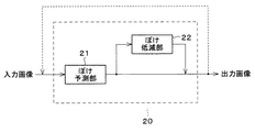
図2は、入力画像がぼけ予測モジュールに送られ、ぼけが存在するか否かが判定され、ぼけが存在すればぼけの量が予測される典型的なぼけ予測・低減システムの一形態を示す。図2において、実線の矢印はこのシステムにおいて必須の信号の流れを示し、破線の矢印は任意の信号の流れを示す。図2に示すように、本発明の画像処理装置の実施の一形態としてのぼけ予測・低減システム20は、ぼけ予測部21とぼけ低減部22とを備えている。
FIG. 2 illustrates one form of a typical blur prediction and reduction system in which an input image is sent to a blur prediction module to determine whether blur is present and, if so, to predict the amount of blur. . In FIG. 2, a solid arrow indicates an essential signal flow in this system, and a dashed arrow indicates an arbitrary signal flow. As shown in FIG. 2, a blur prediction /
ぼけ予測部(ぼけ予測モジュール)21は、ぼけ低減プロセスを適用すべきか否かを判定し、適用すべきであれば、ぼけをどの程度低減させるべきかを決定する。ぼけ低減部22は、ぼけ予測部21の決定に従って画像ぼけを低減させる。ぼけ予測部21およびぼけ低減部22による処理は、望みに応じて繰り返してもよい。例えば、図2に矢印で示すように、入力画像を、ぼけ閾値に到達するまでぼけ予測・低減システム20に繰り返し通して繰り返し処理を行ってもよい。
The blur prediction unit (blur prediction module) 21 determines whether or not the blur reduction process should be applied, and if so, how much the blur should be reduced. The
ほとんどのデジタル画像は、次式 Most digital images have the formula

上記順方向離散コサイン変換は、空間領域におけるデジタル画像の画素情報を周波数領域におけるエネルギーまたはパワーの情報に変換する。周波数領域へのデジタル画像の変換によって、画像が顕著に圧縮可能となり、その結果として格納スペースが節約できる。例として、空間領域に格納された白黒のデジタル画像は、全ての画素が、グレイスケール上における画素の濃淡を表す任意のビット長の数で符号化されることを必要とする。便宜上、デジタル画像は、通常、デジタル画像ファイルの中に格納されるときに、8×8画素のブロックに組織化される。したがって、白黒画像に関する画素情報をデジタル画像ファイルに格納するのに8ビットグレイスケールが使用される場合、デジタル画像ファイルは、連続した8×8の配列に組織化され、かつ、対応する画素の濃淡を表す0〜255の間の値を各々がとる、一連の数を含む。これは、格納に多くの格納空スペースを必要とする。より高いビット長が使用されている場合、さらに大きいスペースが必要である。 The forward discrete cosine transform converts pixel information of a digital image in a spatial domain into energy or power information in a frequency domain. The conversion of the digital image to the frequency domain allows the image to be significantly compressed, thereby saving storage space. By way of example, a black and white digital image stored in the spatial domain requires that all pixels be encoded with a number of arbitrary bit lengths representing the shade of the pixel on a gray scale. For convenience, digital images are typically organized into blocks of 8.times.8 pixels when stored in digital image files. Thus, if 8-bit grayscale is used to store pixel information for a black and white image in a digital image file, the digital image file is organized into a contiguous 8x8 array, and the shading of the corresponding pixels. A series of numbers, each taking a value between 0 and 255 representing This requires a lot of storage empty space for storage. If higher bit lengths are used, more space is needed.
空間領域に格納されたカラー画像は、画素の色情報を適切に保存するために、[R,G,B]または[L,Cr,Cb]などのような3つ(または何らかの数)の成分によって各画素を表すことができるが、この場合、さらに多くの格納スペースを必要とする。例えば、24ビットのY,Cr,Cbのデジタル画像ファイルがカラー画像を格納している場合、デジタルファイルは、3つの個別の8×8配列を含み、各8×8配列は選択された色座標系の1つの成分を表す。各配列の各数は、対応する画素の対応するカラー座標の濃淡を表す8ビットの数、0〜255になる。 The color image stored in the spatial domain has three (or some number) components such as [R, G, B] or [L, Cr, Cb] etc. in order to properly store the color information of the pixels. Can represent each pixel, but this requires more storage space. For example, if a 24-bit Y, Cr, Cb digital image file contains a color image, the digital file will contain three separate 8 × 8 arrays, each 8 × 8 array containing the selected color coordinates. Represents one component of the system. Each number in each array is an 8-bit number, 0 to 255, representing the shade of the corresponding color coordinate of the corresponding pixel.
順方向DCT変換は、各配列を、空間領域の画素情報から、離散的な垂直周波数成分および水平周波数成分の周波数領域におけるエネルギー情報にそれぞれ変換する。空間領域に画像を格納する画像形式のように、周波数領域に画像を格納する画像形式は、典型的には、画像のパワー情報を8×8のブロックに組織化する。言い換えれば、画像のパワー情報は、図3に示すような8×8の格子内に図示している8つの離散的な垂直周波数成分および8つの離散的な水平周波数成分で格納することができる。図3に示すC00項10は、画像のDC(直流)周波数成分、すなわち、ゼロの水平周波数およびゼロの垂直周波数における画像パワーを表す。C07項12は、ゼロの垂直周波数および最高の水平周波数における画像のパワーを表し、C70項14は、ゼロの水平周波数および最高の垂直周波数における画像のパワーを表す。C77項16は、最高の垂直周波数および最高の水平周波数での画像のパワーを表す。
The forward DCT transform converts each array from pixel information in the spatial domain to energy information in the frequency domain of discrete vertical and horizontal frequency components. Image formats that store images in the frequency domain, such as those that store images in the spatial domain, typically organize the power information of the images into 8 × 8 blocks. In other words, the power information of the image can be stored with eight discrete vertical frequency components and eight discrete horizontal frequency components shown in an 8 × 8 grid as shown in FIG.
実際の画像中における大多数のエネルギーまたはパワーは低周波ブロックに含まれるので、周波数領域で符号化されたデジタル画像はより容易に圧縮できる。従って、デジタル画像ファイルが高い垂直周波数および水平周波数の画像情報を切り捨てられるものであれば、まだ、画像のディテールの大部分を保持しながら、表示のための空間領域に画像を復号できるであろう。1つの一般的に使用されているデジタル画像形式は、順方向DCT変換を使用してJPEG(Joint Photographic Experts Group)形式に画像を特徴付けているが、他のデジタル画像形式もまたこの変換を使用している。JPEG形式は、画質の顕著な劣化なしに画像を劇的に圧縮することを可能にするので、画像を特徴付けるのに広く使用されている。 Digital images encoded in the frequency domain can be more easily compressed because the majority of the energy or power in the actual image is contained in the low frequency blocks. Thus, if the digital image file is capable of truncating high vertical and horizontal frequency image information, it will still be able to decode the image into a spatial domain for display while preserving most of the image details. . One commonly used digital image format uses forward DCT transforms to characterize images in the JPEG (Joint Photographic Experts Group) format, but other digital image formats also use this transform. are doing. The JPEG format is widely used to characterize images because it allows images to be compressed dramatically without significant degradation of image quality.
上述した順方向DCT変換は、パワースペクトル分析で使用される連続したフーリエ変換と際立って類似している。この事実から、本願発明者は、画像ぼけの量が画像のパワースペクトルから予測できるのと丁度同じように、ほとんどの圧縮されたデジタル画像ファイルに既に埋め込まれたDCT情報から画像ぼけを認識できるであろうと推論した。したがって、DCT係数を含むデジタル画像の画像ぼけを予測するときに、パワースペクトル分析の実行にかかわる計算の複雑さが回避可能であろう。 The forward DCT transform described above is strikingly similar to the continuous Fourier transform used in power spectrum analysis. This fact allows the inventors to recognize image blur from DCT information already embedded in most compressed digital image files, just as the amount of image blur can be predicted from the power spectrum of the image. I inferred that. Thus, when predicting image blur of a digital image that includes DCT coefficients, the computational complexity involved in performing a power spectrum analysis could be avoided.
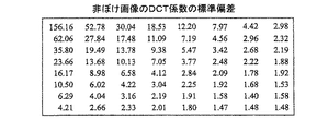
この考えで、本願発明者は、デジタル画像の画像ぼけの量を予測するのに使用可能な、デジタル画像ファイル中に既に埋め込まれたさまざまな情報が本当にあると断定した。例として、図4および図5は、「ぼけ指標」と呼ばれる、そのような画像ぼけの尺度の1つを示す。図4は、複数のブロックを処理した結果として得られる非ぼけ画像に関する、各周波数におけるDCT値の標準偏差を示す表である。図5は、複数のブロックを処理した結果として得られるぼけ画像に関する、各周波数におけるDCT値の標準偏差を示す表である。これら2つの表の比較から分かるように、低周波でのぼけ画像と非ぼけ画像との標準偏差は、ほとんど同じである。しかしながら、周波数が垂直成分および水平成分の両方で増加するのに従って、ぼけ画像のための標準偏差が非ぼけ画像のものより劇的に低下する。したがって、デジタル画像ファイル中におけるDCT係数の標準偏差は、ぼけ指標として効果的に使用できる。画像ぼけを効果的に予測できることがわかった他の指標は、最大のDCT係数、最小のDCT係数、分散、および尖度またはモーメント(Kurtosis)を含んでいる。さらに、画像ぼけは、DCT係数の標準偏差を2次元(水平および垂直)のDCT周波数成分の関数として表す表面の下の体積として図6に図示している画像ブロック内における係数の標準偏差の合計から予測できる。 In this regard, the present inventors have determined that there is indeed a variety of information already embedded in a digital image file that can be used to predict the amount of image blur in a digital image. As an example, FIGS. 4 and 5 show one such measure of image blur, called the "blur index". FIG. 4 is a table showing the standard deviation of the DCT value at each frequency for a non-blurred image obtained as a result of processing a plurality of blocks. FIG. 5 is a table showing the standard deviation of the DCT value at each frequency for a blurred image obtained as a result of processing a plurality of blocks. As can be seen from a comparison of these two tables, the standard deviation between the blurred image at low frequencies and the non-blurred image is almost the same. However, as the frequency increases in both the vertical and horizontal components, the standard deviation for blurred images drops dramatically than that of non-blurred images. Therefore, the standard deviation of the DCT coefficients in the digital image file can be used effectively as a blur index. Other indicators that have been found to be able to effectively predict image blur include the largest DCT coefficient, the smallest DCT coefficient, variance, and kurtosis or Kurtosis. In addition, image blur is the sum of the standard deviation of the coefficients within the image block illustrated in FIG. 6 as the volume below the surface representing the standard deviation of the DCT coefficients as a function of the two-dimensional (horizontal and vertical) DCT frequency components. Can be predicted from
ぼけ指標は、単一のDCT係数(生の、または、修正された)であってもよく、1セットの複数のDCT係数(生の、または、修正された)であってもよく、他のDCT係数に対する1つ以上のDCT係数の比較結果(生の、または、修正された)であってもよい。どの場合でも、ゼロ以外あるいはノンゼロのDCT係数の大きさの変化は、ぼけの予測および/または低減における変化をもたらしうる。 The blur index may be a single DCT coefficient (raw or modified), a set of multiple DCT coefficients (raw or modified), another It may be a comparison (raw or modified) of one or more DCT coefficients to DCT coefficients. In any case, a change in the magnitude of non-zero or non-zero DCT coefficients may result in a change in blur prediction and / or reduction.
なお、JPEGなどの典型的なデジタル画像形式では、デジタル画像ファイルは、画像の空間的な一部分に対する空間的なドメインの画素情報に各ブロックが対応する、DCT係数の多くのブロックを含みうる。したがって、画像の異なる複数の空間部分からのDCT係数の1つ以上のセット(「生」の、または、統計的に修正された)から適切なぼけ指標を選択することで、上記技術は、画像の個々の領域での画像ぼけの検出を可能にする。多くの画像が画像の一部分の被写体部分に焦点を合わせる一方、画像の残りをぼかすよう意図されているので、これは強力なツールである。画像内における何らかの領域がぼけていないかを示すのに使用可能なぼけ指標は、所定の周波数におけるデジタル画像の最大のDCT係数である。ぼけの存在のために1以上のブロックのDCT係数を含む画像の個々の領域を調べる能力でもって、そのような部分的にぼけている画像を特定できるので、そのような画像をうかつに修正してしまうことはない。 Note that in a typical digital image format such as JPEG, a digital image file may include many blocks of DCT coefficients, with each block corresponding to spatial domain pixel information for a spatial portion of the image. Thus, by selecting the appropriate blur index from one or more sets of DCT coefficients ("raw" or statistically modified) from different spatial portions of the image, the techniques described above can be applied to the image. Enables detection of image blur in individual regions of the image. This is a powerful tool because many images are intended to focus on the subject portion of a portion of the image while blurring the rest of the image. A blur index that can be used to indicate whether any region in the image is blurred is the largest DCT coefficient of the digital image at a given frequency. The ability to examine individual regions of an image that contains DCT coefficients of one or more blocks due to the presence of blur can identify such partially blurred images, so that such images can be corrected inadvertently. You won't.
図7は、ぼけ予測・低減技術の一例を示す。この例では、2次元(「2D」)のヒストグラムがデジタル画像ファイルから構築されているので、画像ファイル中の各DCT係数はその対応する周波数成分と関連付けられている。そして、上記周波数成分は、2次元である。すなわち、上記周波数成分は、垂直周波数値および水平周波数値の両方を示す。 FIG. 7 shows an example of a blur prediction / reduction technique. In this example, since a two-dimensional ("2D") histogram is constructed from the digital image file, each DCT coefficient in the image file is associated with its corresponding frequency component. The frequency component is two-dimensional. That is, the frequency component indicates both a vertical frequency value and a horizontal frequency value.
デジタル画像ファイル内の各画像ブロックは、図3で例示した2次元(8×8)DCT周波数成分に対応する64個の係数を含みうる。2次元ヒストグラムは、画像ファイルの中のDCT係数の各々を、それに関連付けられた特定の2次元周波数成分に従って組織化する。JPEGなどのようなほとんどのデジタル画像符号化スキームは、順方向DCT変換からDCT係数を計算した後にさらにDCT係数を修正している。JPEGは、例えば、量子化テーブル(Qテーブル)に応じて各ブロック内のそれぞれのDCT係数を量子化した後、より効率的な圧縮を提供するためにハフマン符号化スキームで値を符号化する。従って、このプロセスでJPEGファイルが使用されている場合、2次元ヒストグラムが得られる前にハフマン符号化および量子化を取り除くべきである。 Each image block in the digital image file may include 64 coefficients corresponding to the two-dimensional (8 × 8) DCT frequency components illustrated in FIG. The two-dimensional histogram organizes each of the DCT coefficients in the image file according to a particular two-dimensional frequency component associated therewith. Most digital image encoding schemes, such as JPEG, further modify the DCT coefficients after calculating the DCT coefficients from the forward DCT transform. JPEG, for example, quantizes each DCT coefficient in each block according to a quantization table (Q table) and then encodes values in a Huffman coding scheme to provide more efficient compression. Therefore, if a JPEG file is used in this process, Huffman coding and quantization should be removed before a two-dimensional histogram is obtained.
そこで、この2Dヒストグラムを、半径方向の周波数パワースペクトルと概ね同等な1次元(「1D」)のヒストグラムに変換してもよい。マッピング関数に従って2Dヒストグラムを1Dヒストグラムに変換してもよい。図8は、1つの適切なマッピング関数を示す。図5から分かるように、ブロック内でのそれらの位置に応じて、64個のDCT周波数成分が複数のグループ(例えば0〜7のグループ)に分割される。これらのグループは、DC周波数成分に対して同心円状の領域へ大まかに組織化できる。この特定のマッピング関数内の複数領域中のDCT係数の各々が、所定の画像ブロックにおいて互いに近接した値を持つことが一般に観測されたので、この特定のマッピング関数内の領域が選択される。2次元ヒストグラムを1次元のヒストグラムに変換する1つの技術は、所定の画像ブロック内の各領域に対応する複数のDCT係数をまとめて平均化し、中央値を与えるものである。代わりに、単に、その領域に対する値を表すように各領域内の1つの値を選択してもよい。本質的には、これは、2次元ヒストグラムを無次元のヒストグラムに変換するか、さもなければ、データ量を低減させる。0〜7の値は、一般に増加する半径方向の周波数成分を表す。
Therefore, the 2D histogram may be converted into a one-dimensional (“1D”) histogram substantially equivalent to the frequency power spectrum in the radial direction. The 2D histogram may be converted into a 1D histogram according to a mapping function. FIG. 8 shows one suitable mapping function. As can be seen from FIG. 5, the 64 DCT frequency components are divided into a plurality of groups (for example,
ここで説明した複数ステップは、逆の順序で実行してもよい。すなわち、各画像ブロックはデジタル画像ファイルから読み込まれるので、図8に示すマッピング関数は、まず、各領域0〜7に対する中央値を得ることによってブロックを1次元に変換するのに使用することもできる。そこで、1次元のヒストグラムは、追加画像ブロックが読み込まれ、変換され、それらの中央値がそれらの関連領域に分類されるように、構成することもできる。 The steps described herein may be performed in reverse order. That is, since each image block is read from a digital image file, the mapping function shown in FIG. 8 can also be used to convert the block to one dimension by first obtaining the median for each region 0-7. . Thus, the one-dimensional histogram can be configured such that additional image blocks are read and transformed, and their median values are classified into their associated regions.
DCT係数の異なるセットの選択は、望みに応じて部分的に重複していてもよいが、重複していないことが好ましい。これらのセットは、好ましくは、より高い周波数やより低い周波数などのような異なる複数の周波数成分を含む。異なる周波数値は、大きさの変化の比較を周波数の関数として容易に可能とする。 The selection of different sets of DCT coefficients may partially overlap as desired, but preferably do not. These sets preferably include different frequency components, such as higher and lower frequencies. Different frequency values facilitate comparison of magnitude changes as a function of frequency.
1次元のヒストグラムから、1つ以上のぼけ指標を得ることもできる。使用可能な第1のぼけ指標は、領域5内の最大のDCT係数(あるいは何らかの他の領域または係数)である。本願発明者は、第1の指標に対するこの領域内の100の閾値が、デジタルカメラから得られる画像のぼけに対する適当な指標であると決定した。最大のDCT係数が閾値より小さいか否かを検査することによって、フォーカスには画像の何らかの部分が焦点のあった状態であるか否かを正確に判定することができる。すなわち、領域5内の最大のDCT係数が100未満であるなら、典型的には画像全体がぼけているであろう。逆に、領域5内の最大のDCT係数が100以上であれば、おそらく画像の少なくとも一部分が焦点のあった状態であろう。
One or more blur indices can also be obtained from the one-dimensional histogram. The first blur index that can be used is the largest DCT coefficient in region 5 (or some other region or coefficient). The inventor has determined that a threshold of 100 in this region for the first index is a suitable indicator for blurring of the image obtained from the digital camera. By examining whether the maximum DCT coefficient is less than a threshold, it is possible to accurately determine whether any part of the image is in focus. That is, if the largest DCT coefficient in
使用可能な第2のぼけ指標は、第3の領域の標準偏差に対する第1の領域の標準偏差の比(または何らかの他の2つ以上の領域間の比較)である。ぼけ画像内におけるDCT係数の標準偏差は、周波数の増加に応じて非ぼけ画像よりも急速に低下する傾向がある。したがって、比較的高い比はぼけ画像を示すが、比較的低い比は焦点の合った画像を示す。本願発明者は、このぼけ指標のための5の閾値が、デジタルカメラからの画像のための画像ぼけの適切な指標であると決定した。標準偏差の指標は画像全体にわたって情報を平均化するので、このぼけ指標は、画像における焦点のあった孤立部分を検出する傾向がないが、代わりに全体的な画像ぼけを評価する傾向があるであろう。 A second blur index that can be used is the ratio of the standard deviation of the first region to the standard deviation of the third region (or a comparison between some other two or more regions). The standard deviation of the DCT coefficients in blurred images tends to decrease more rapidly with increasing frequency than in non-blurred images. Thus, a relatively high ratio indicates a blurred image, while a relatively low ratio indicates a focused image. The inventor has determined that a threshold of 5 for this blur index is a suitable indicator of image blur for images from digital cameras. Since the standard deviation index averages the information over the entire image, this blur index does not tend to detect focused isolated parts of the image, but instead tends to evaluate the overall image blur. There will be.
前述した技術は、第1の指標として領域5内の最大のDCT係数を使用し、第2のぼけ指標として領域3のDCT係数の比率に対する領域1のDCT係数の標準偏差の比を使用していたが、他の技術は、他の領域からの他のぼけ指標を使用してもよい。同様に、最小の係数値などのような他の統計的な値もまた、ぼけ指標として使用できる。また、上述した技術は1次元のヒストグラムからぼけ指標を計算していたが、ヒストグラムなしにぼけ指標を導き出してもよい。例えば、選択されるぼけ指標は、領域5の最大の係数と、領域1の係数の平均に対する領域3の係数の平均の比とであってもよい。この場合、単に、データがデジタル画像ファイルから読み込まれるにしたがって、これらのぼけ指標を計算および更新することができる。
The technique described above uses the largest DCT coefficient in
図7に示す2つのぼけ指標から異なるぼけ予測を計算してもよい。第1に、第1の指標が100未満であり、第2のぼけ指標が5以上であれば、画像全体はかなりぼけているであろう。この条件が成立している場合、画像を強調するために最強の反ぼけフィルタを適用することができる。 Different blur predictions may be calculated from the two blur indices shown in FIG. First, if the first index is less than 100 and the second blur index is 5 or more, the entire image will be fairly blurred. If this condition is met, the strongest anti-blur filter can be applied to enhance the image.
第2に、第1の指標が100未満であり、第2のぼけ指標が5未満であれば、画像全体がわずかにぼけているであろう。この場合、画像を強調するために中程度の反ぼけフィルタを適用することができる。 Second, if the first index is less than 100 and the second blur index is less than 5, the entire image will be slightly blurred. In this case, a moderate anti-blur filter can be applied to enhance the image.
第3に、第1の指標が100以上であり、第2のぼけ指標が3以上5未満であれば、画像中の物体に焦点が合っているが、画像はわずかに鮮鋭度を欠くであろう。そこで、この場合、画像を強調するために標準の鮮鋭度強調フィルタを適用することができる。 Third, if the first index is greater than or equal to 100 and the second blur index is greater than or equal to 3 and less than 5, the object in the image is in focus, but the image is slightly less sharp. Would. Thus, in this case, a standard sharpness enhancement filter can be applied to enhance the image.
第4に、第1の指標が100以上であり、第2のぼけ指標が5以上であれば、画像は鮮鋭度をかなり欠くであろう。この場合、強い鮮鋭度強調フィルタを適用することができる。 Fourth, if the first index is greater than or equal to 100 and the second blur index is greater than or equal to 5, the image will be significantly less sharp. In this case, a strong sharpness enhancement filter can be applied.
本実施形態では、第1のぼけ指標が閾値以上か否かの判定結果に基づいて、「反ぼけフィルタ」と「鮮鋭度強調フィルタ」とを切り替える。すなわち、第1のぼけ指標が閾値未満と判定された画像に対しては「反ぼけフィルタ」を、第1のぼけ指標が閾値以上と判定された画像に対しては「鮮鋭度強調フィルタ」を使用する。また、第2のぼけ指標によっても、それぞれのフィルタ特性を変更する。 In the present embodiment, an “anti-blur filter” and a “sharpness enhancement filter” are switched based on the determination result of whether or not the first blur index is equal to or greater than a threshold. That is, an “anti-blur filter” is applied to an image in which the first blur index is determined to be less than the threshold, and a “sharpness enhancement filter” is applied to an image in which the first blur index is determined to be equal to or more than the threshold. use. Also, each filter characteristic is changed by the second blur index.
この段落で説明したフィルタは、良く知られており、それらの設計は当業者にとって容易である。「反ぼけフィルタ」は、ぼけた画像を修復する目的で使用するフィルタである。「反ぼけフィルタ」と「鮮鋭度強調フィルタ」とのフィルタ特性の違いは、「反ぼけフィルタ」は、ぼけ補正をするフィルタ、「鮮鋭度強調フィルタ」は、画質改善の観点から鮮鋭度強調を行うフィルタである。そのため、両者の違いは、強調する周波数帯域にある。「反ぼけフィルタ」は、典型的に画像全体がぼけているであろうという予測に基づき、適応的な補正を行うために、あまり高周波領域を強調せず、人間がその画像に対してぼけていると感じ易い比較的中周波である領域に対し強調を行い(強調するバンドを限定している)である。これに対し、「鮮鋭度強調フィルタ」は、高周波領域に行くに従って強調度合いを高く設定するフィルタである。 The filters described in this paragraph are well known and their design is straightforward for a person skilled in the art. “Anti-blur filter” is a filter used for the purpose of restoring a blurred image. The difference between the filter characteristics of the "anti-blur filter" and the "sharpness enhancement filter" is that the "anti-blur filter" is a filter for blur correction, and the "sharpness enhancement filter" is a filter for sharpness enhancement from the viewpoint of image quality improvement. It is a filter to be performed. Therefore, the difference between the two lies in the frequency band to be emphasized. An "anti-blur filter" is based on the prediction that the entire image will typically be blurred, and does not emphasize too much high-frequency regions to make adaptive corrections, so that The emphasis is given to the region having a relatively medium frequency, which is easy to feel as if it is present (the band to be emphasized is limited). On the other hand, the “sharpness enhancement filter” is a filter that sets the enhancement degree higher as it goes to a higher frequency region.
なお、図7では、4つの説明したフィルタの中の1つを適用した後に終了する技術を示しているが、補正された画像で上記処理を繰り返し、さらなるぼけ補正が必要であるかどうかを確認することも可能である。 Note that FIG. 7 shows a technique that terminates after applying one of the four described filters. However, the above processing is repeated on the corrected image to check whether further blur correction is necessary. It is also possible.
次に、本発明に係る画像処理装置の実施の一形態について、図9に基づいて説明する。 Next, an embodiment of an image processing apparatus according to the present invention will be described with reference to FIG.
本形態の画像処理装置は、入力デジタル画像ファイルに対し、該入力デジタル画像ファイル中にDCT係数の配列として格納されたデジタル画像のぼけを検出する処理を行い、その検出結果に基づいてデジタル画像を修正する画像処理装置である。入力デジタル画像ファイルにおいて、上記DCT係数の配列が水平周波数成分および垂直周波数成分の格子を表す複数のブロック内に配列され、上記各ブロックが画像の部分を表す。 The image processing apparatus according to the present embodiment performs a process for detecting a blur of a digital image stored as an array of DCT coefficients in the input digital image file on the input digital image file, and converts the digital image based on the detection result. This is an image processing device to be corrected. In the input digital image file, the array of DCT coefficients is arranged in a plurality of blocks representing a grid of horizontal and vertical frequency components, each block representing a portion of the image.
図9に示すように、本形態の画像処理装置は、入力デジタル画像ファイルのDCT係数の配列から複数のDCT係数を読み込むDCT係数読み込み部1と、上記複数のDCT係数から第1のぼけ指標を計算する第1のぼけ指標計算部2と、上記複数のDCT係数から第2のぼけ指標を計算する第2のぼけ指標計算部3と、上記入力デジタル画像ファイルに対し、上記第1のぼけ指標および上記第2のぼけ指標の値に基づいて選択的にフィルタを適用するフィルタ処理部4とを備えている。
As shown in FIG. 9, the image processing apparatus according to the present embodiment includes a DCT
DCT係数読み込み部1は、入力デジタル画像ファイルの各ブロックから少なくとも2つのDCT係数を読み込む。また、本形態では、第1のぼけ指標は、全てのブロックの中で最小のぼけ量を持つブロックのぼけ量を数値として表し、第2のぼけ指標は、上記デジタル画像の全体としてのぼけ量を数値として表す。
The DCT
フィルタ処理部4は、反ぼけ効果(ぼけをなくす効果)および鮮鋭度強調効果の異なる4つのフィルタ処理部、第1の反ぼけフィルタ処理部6、第2の反ぼけフィルタ処理部7、第1の鮮鋭度強調フィルタ処理部8、および第2の鮮鋭度強調フィルタ処理部9を備えている。第1の反ぼけフィルタ処理部6は、標準より強い反ぼけフィルタ処理を行うものであり、第2の反ぼけフィルタ処理部7は、標準の反ぼけフィルタ処理を行うものである。第1の鮮鋭度強調フィルタ処理部8は、標準の鮮鋭度強調フィルタ処理を行うものであり、第2の鮮鋭度強調フィルタ処理部9は、標準より強い鮮鋭度強調フィルタ処理を行う
ものである。
The
そして、フィルタ処理部4は、フィルタ選択部5を備えている。このフィルタ選択部5が、上記第1のぼけ指標および上記第2のぼけ指標の値に基づいて、4つのフィルタ処理部、第1の反ぼけフィルタ処理部6、第2の反ぼけフィルタ処理部7、第1の鮮鋭度強調フィルタ処理部8、および第2の鮮鋭度強調フィルタ処理部9の何れかを選択し、選択したフィルタ処理部に対して入力デジタル画像ファイルを送り、フィルタ処理させるようになっている。そして、4つのフィルタ処理部の何れかでフィルタ処理されたデジタル画像ファイルが、出力デジタル画像ファイルとして出力される。
The
図9の画像処理装置を構成する各部、すなわち、DCT係数読み込み部1、第1のぼけ指標計算部2、第2のぼけ指標計算部3、フィルタ選択部5、第1の反ぼけフィルタ処理部6、第2の反ぼけフィルタ処理部7、第1の鮮鋭度強調フィルタ処理部8、および第2の鮮鋭度強調フィルタ処理部9は、CPUが記憶装置に格納されたプログラムを実行し、図示しない入出力回路などの周辺回路を制御することによって実現される機能ブロックである。
The components constituting the image processing apparatus of FIG. 9, that is, the DCT
次に、本発明に係る画像処理装置の他の実施の形態について、図10に基づいて説明する。なお、説明の便宜上、図9に示す各部材と同一の機能を有する部材には、同一の符号を付記し、その説明を省略する。 Next, another embodiment of the image processing apparatus according to the present invention will be described with reference to FIG. For convenience of explanation, members having the same functions as those shown in FIG. 9 are denoted by the same reference numerals, and description thereof is omitted.
図10に示すように、本形態の画像処理装置は、DCT係数読み込み部1に代えて、DCT係数の2次元のヒストグラムを作成する2次元ヒストグラム作成部11と、上記2次元のヒストグラムを1次元のヒストグラムに変換するヒストグラム変換部12とを備え、第1のぼけ指標計算部2および第2のぼけ指標計算部3が、上記1次元のヒストグラムからぼけ指標(第1のぼけ指標または第2のぼけ指標)を計算するようになっている以外は、前記の図9に示す画像処理装置と同様である。
As shown in FIG. 10, the image processing apparatus according to the present embodiment includes a two-dimensional
図10の画像処理装置を構成する各部、すなわち、第1のぼけ指標計算部2、第2のぼけ指標計算部3、フィルタ選択部5、第1の反ぼけフィルタ処理部6、第2の反ぼけフィルタ処理部7、第1の鮮鋭度強調フィルタ処理部8、第2の鮮鋭度強調フィルタ処理部9、2次元ヒストグラム作成部11、およびヒストグラム変換部12は、CPUが記憶装置に格納されたプログラムを実行し、図示しない入出力回路などの周辺回路を制御することによって実現される機能ブロックである。
The components constituting the image processing apparatus of FIG. 10, that is, the first
なお、上記実施形態では、画像処理装置を構成する各部が、「CPUなどの演算手段がROMやRAMなどの記録媒体に格納されたプログラムコードを実行することで実現される機能ブロックである」場合を例にして説明したが、同様の処理を行うハードウェアで実現してもよい。また、処理の一部を行うハードウェアと、当該ハードウェアの制御や残余の処理を行うプログラムコードを実行する上記演算手段とを組み合わせても実現することもできる。さらに、上記各部材のうち、ハードウェアとして説明した部材であっても、処理の一部を行うハードウェアと、当該ハードウェアの制御や残余の処理を行うプログラムコードを実行する上記演算手段とを組み合わせても実現することもできる。なお、上記演算手段は、単体であってもよいし、装置内部のバスや種々の通信路を介して接続された複数の演算手段が共同してプログラムコードを実行してもよい。 In the above embodiment, each of the units constituting the image processing apparatus is a “functional block realized by an arithmetic unit such as a CPU executing a program code stored in a recording medium such as a ROM or a RAM”. Has been described as an example, but it may be realized by hardware that performs the same processing. Further, the present invention can also be realized by combining hardware for performing a part of the processing and the above-described arithmetic means for executing a program code for controlling the hardware and performing the remaining processing. Furthermore, among the above-mentioned members, even if the member is described as hardware, hardware for performing a part of the processing and the arithmetic means for executing the program code for controlling the hardware and performing the remaining processing are included. Combinations can also be realized. The arithmetic means may be a single unit, or a plurality of arithmetic means connected via a bus or various communication paths inside the apparatus may execute the program code in cooperation.
上記演算手段によって直接実行可能なプログラムコード自体、または、後述する解凍などの処理によってプログラムコードを生成可能なデータとしてのプログラムは、当該プログラム(プログラムコードまたは上記データ)を記録媒体に格納し、当該記録媒体を配付したり、あるいは、上記プログラムを、有線または無線の通信路を介して伝送するための通信手段で送信したりして配付され、上記演算手段で実行される。 The program code itself directly executable by the arithmetic means or a program as data capable of generating a program code by a process such as decompression described below stores the program (program code or the data) in a recording medium, and The program is distributed by distributing a recording medium or transmitted by a communication means for transmitting the program via a wired or wireless communication path, and is executed by the arithmetic means.
なお、通信路を介して伝送する場合、通信路を構成する各伝送媒体が、プログラムを示す信号列を伝搬し合うことによって、当該通信路を介して、上記プログラムが伝送される。また、信号列を伝送する際、送信装置が、プログラムを示す信号列により搬送波を変調することによって、上記信号列を搬送波に重畳してもよい。この場合、受信装置が搬送波を復調することによって信号列が復元される。一方、上記信号列を伝送する際、送信装置が、デジタルデータ列としての信号列をパケット分割して伝送してもよい。この場合、受信装置は、受信したパケット群を連結して、上記信号列を復元する。また、送信装置が、信号列を送信する際、時分割/周波数分割/符号分割などの方法で、信号列を他の信号列と多重化して伝送してもよい。この場合、受信装置は、多重化された信号列から、個々の信号列を抽出して復元する。いずれの場合であっても、通信路を介してプログラムを伝送できれば、同様の効果が得られる。 In the case of transmission via a communication path, the transmission medium that forms the communication path propagates a signal sequence indicating the program, whereby the program is transmitted via the communication path. Further, when transmitting the signal sequence, the transmitting device may superimpose the signal sequence on the carrier wave by modulating the carrier with a signal sequence indicating a program. In this case, the signal sequence is restored by the receiving device demodulating the carrier. On the other hand, when transmitting the signal sequence, the transmitting device may divide the signal sequence as a digital data sequence into packets and transmit the packet. In this case, the receiving device concatenates the received packet groups and restores the signal sequence. Further, when transmitting the signal sequence, the transmitting device may multiplex the signal sequence with another signal sequence and transmit the signal sequence by a method such as time division / frequency division / code division. In this case, the receiving device extracts and restores each signal sequence from the multiplexed signal sequence. In any case, if the program can be transmitted via the communication path, the same effect can be obtained.
ここで、プログラムを配付する際の記録媒体は、取外し可能である方が好ましいが、プログラムを配付した後の記録媒体は、取外し可能か否かを問わない。また、上記記録媒体は、プログラムが記憶されていれば、書換え(書き込み)可能か否か、揮発性か否か、記録方法および形状を問わない。記録媒体の一例として、磁気テープやカセットテープなどのテープ、あるいは、フロッピー(登録商標)ディスクやハードディスクなどの磁気ディスク、または、CD−ROMや光磁気ディスク(MO)、ミニディスク(MD)やデジタルビデオディスク(DVD)などのディスクが挙げられる。また、記録媒体は、ICカードや光カードのようなカード、あるいは、マスクROMやEPROM、EEPROMまたはフラッシュROMなどのような半導体メモリであってもよい。あるいは、CPUなどの演算手段内に形成されたメモリであってもよい。 Here, it is preferable that the recording medium for distributing the program is removable, but the recording medium after distributing the program does not matter whether or not it is removable. In addition, as long as the program is stored, the recording medium is irrespective of whether it is rewritable (writable), whether it is volatile, and the recording method and shape. Examples of the recording medium include a tape such as a magnetic tape and a cassette tape, a magnetic disk such as a floppy (registered trademark) disk and a hard disk, a CD-ROM, a magneto-optical disk (MO), a mini disk (MD), and a digital disk. Discs such as a video disc (DVD) are included. The recording medium may be a card such as an IC card or an optical card, or a semiconductor memory such as a mask ROM, EPROM, EEPROM, or flash ROM. Alternatively, it may be a memory formed in arithmetic means such as a CPU.
なお、上記プログラムコードは、上記各処理の全手順を上記演算手段へ指示するコードであってもよいし、所定の手順で呼び出すことで、上記各処理の一部または全部を実行可能な基本プログラム(例えば、オペレーティングシステムやライブラリなど)が既に存在していれば、当該基本プログラムの呼び出しを上記演算手段へ指示するコードやポインタなどで、上記全手順の一部または全部を置き換えてもよい。 The program code may be a code for instructing the arithmetic means in all the procedures of the respective processes, or may be a basic program capable of executing a part or all of the respective processes by being called in a predetermined procedure. If an operating system or library (for example, an operating system or a library) already exists, a part or all of the entire procedure may be replaced with a code or a pointer that instructs the arithmetic unit to call the basic program.
また、上記記録媒体にプログラムを格納する際の形式は、例えば、実メモリに配置した状態のように、演算手段がアクセスして実行可能な格納形式であってもよいし、実メモリに配置する前で、演算手段が常時アクセス可能なローカルな記録媒体(例えば、実メモリやハードディスクなど)にインストールした後の格納形式、あるいは、ネットワークや搬送可能な記録媒体などから上記ローカルな記録媒体にインストールする前の格納形式などであってもよい。また、プログラムは、コンパイル後のオブジェクトコードに限るものではなく、ソースコードや、インタプリトまたはコンパイルの途中で生成される中間コードとして格納されていてもよい。いずれの場合であっても、圧縮された情報の解凍、符号化された情報の復号、インタプリト、コンパイル、リンク、または、実メモリへの配置などの処理、あるいは、各処理の組み合わせによって、上記演算手段が実行可能な形式に変換可能であれば、プログラムを記録媒体に格納する際の形式に拘わらず、同様の効果を得ることができる。 The format in which the program is stored in the recording medium may be a storage format that can be accessed and executed by the arithmetic unit, such as a state where the program is stored in the real memory, or may be stored in the real memory. Previously, the storage means is installed on a local recording medium (for example, a real memory or a hard disk) which is always accessible by the arithmetic means, or is installed on the local recording medium from a network or a transportable recording medium. The previous storage format may be used. Further, the program is not limited to the compiled object code, but may be stored as a source code or an intermediate code generated during the interpretation or compilation. In any case, the above operation is performed by processing such as decompression of compressed information, decoding of encoded information, interpreting, compiling, linking, or allocating to real memory, or a combination of the processings. If the means can be converted into an executable format, the same effect can be obtained irrespective of the format in which the program is stored in the recording medium.
以上の明細書で使用した用語および表現は、あくまでも本発明を説明するものであり、本発明を制限するものではなく、そのような用語および表現の使用において図示および説明した特徴の等価物を排除する意図はなく、本発明の範囲は請求項によって定義および限定されるものと解釈されるべきである。 The terms and expressions used in the above specification are only descriptions of the present invention and do not limit the present invention, and exclude the equivalents of the features shown and described in the use of such terms and expressions. It is not intended to be construed, and the scope of the invention should be construed as being defined and limited by the claims.
本発明に係る画像処理方法および画像処理装置、並びに画像処理プログラムおよびそれを記録した記録媒体は、JPEG形式などのようなデジタル画像をDCT係数の配列として格納する形式のデジタル画像ファイルに対して画像のぼけを低減する画像処理を効率的に行うことを可能にする。したがって、本発明は、デジタルカメラ等のような画像入力装置、インクジェットプリンタや熱転写プリンタ等のような画像出力装置、画像処理プログラムをインストールしたコンピュータ・システム等のような画像処理システム等の用途において有用である。 An image processing method and an image processing apparatus according to the present invention, and an image processing program and a recording medium on which the image processing program is recorded are used to store an image in a digital image file of a format in which a digital image such as JPEG format is stored as an array of DCT coefficients It is possible to efficiently perform image processing for reducing blur. Therefore, the present invention is useful in applications such as an image input device such as a digital camera, an image output device such as an inkjet printer or a thermal transfer printer, and an image processing system such as a computer system in which an image processing program is installed. It is.
1 DCT係数読み込み部
2 第1のぼけ指標計算部(ぼけ指標計算部)
3 第2のぼけ指標計算部(ぼけ指標計算部)
4 フィルタ処理部
5 フィルタ選択部
6 第1の反ぼけフィルタ処理部
7 第2の反ぼけフィルタ処理部
8 第1の鮮鋭度強調フィルタ処理部
9 第2の鮮鋭度強調フィルタ処理部
11 2次元ヒストグラム作成部
12 ヒストグラム変換部
20 ぼけ予測・低減システム(画像処理装置)
21 ぼけ予測部
22 ぼけ低減部
1 DCT
3 Second blur index calculator (blur index calculator)
21
Claims (21)
(a)上記DCT係数の配列で構成される各ブロックから少なくとも2つのDCT係数を読み込むように複数のDCT係数を読み込むステップと、
(b)上記複数のDCT係数から、全てのブロックの中で最小のぼけ量を持つブロックのぼけ量を数値として表す第1のぼけ指標を計算するステップと、
(c)上記複数のDCT係数から、上記デジタル画像の全体としてのぼけ量を数値として表す第2のぼけ指標を計算するステップと、
(d)上記デジタル画像に対し、上記第1のぼけ指標および上記第2のぼけ指標の値に基づいて選択的にフィルタを適用するステップとを含むことを特徴とする画像処理方法。 A digital image stored as an array of DCT coefficients in a digital file, wherein the array of DCT coefficients is arranged in a plurality of blocks representing a lattice of frequency components, each of the blocks being a digital image representing a portion of the image. An image processing method for detecting and correcting blur of a digital image,
(A) reading a plurality of DCT coefficients so as to read at least two DCT coefficients from each block constituted by the array of DCT coefficients;
(B) calculating, from the plurality of DCT coefficients, a first blur index representing a blur amount of a block having a minimum blur amount among all blocks as a numerical value;
(C) calculating, from the plurality of DCT coefficients, a second blur index representing the overall blur amount of the digital image as a numerical value;
(D) selectively applying a filter to the digital image based on the values of the first blur index and the second blur index.
上記第1のぼけ指標は、画像内の全てのブロックにおける上記周波数成分でのDCT係数の中の最大値であることを特徴とする請求項1記載の画像処理方法。 Selecting a representative frequency component in the grid,
The image processing method according to claim 1, wherein the first blur index is a maximum value of DCT coefficients of the frequency components in all blocks in the image.
上記第2のぼけ指標は、これら標準偏差の比であることを特徴とする請求項1記載の画像処理方法。 Selecting two representative frequency components in the grid and calculating the standard deviation of the DCT coefficients at these two representative frequency components over the entire image;
2. The image processing method according to claim 1, wherein the second blur index is a ratio of these standard deviations.
(f)各ブロックの各領域におけるDCT係数をまとめるステップとをさらに含み、
第1のぼけ指標を計算するステップおよび第2のぼけ指標を計算するステップでは、上記まとめられたDCT係数から、上記第1のぼけ指標および第2のぼけ指標を計算することを特徴とする請求項1記載の画像処理方法。 (E) dividing the frequency component grid into a plurality of regions of increasing frequency;
(F) summing DCT coefficients in each region of each block;
The step of calculating a first blur index and the step of calculating a second blur index include calculating the first blur index and the second blur index from the combined DCT coefficients. Item 10. The image processing method according to Item 1.
(a)DCT係数の2次元のヒストグラムを得るステップと、
(b)上記2次元のヒストグラムを1次元のヒストグラムにまとめるステップと、
(c)上記1次元のヒストグラムから少なくとも1つのぼけ指標を計算するステップと、
(d)上記デジタル画像に対し、上記少なくとも1つのぼけ指標に基づいて選択的にフィルタを適用するステップとを含むことを特徴とする画像処理方法。 A digital image stored as an array of DCT coefficients in a digital file, wherein the array of DCT coefficients is arranged in a plurality of blocks representing a grid of horizontal frequency components and vertical frequency components, and each block represents a portion of the image. An image processing method for detecting and correcting blur of the digital image with respect to the digital image represented,
(A) obtaining a two-dimensional histogram of DCT coefficients;
(B) combining the two-dimensional histogram into a one-dimensional histogram;
(C) calculating at least one blur index from the one-dimensional histogram;
(D) selectively applying a filter to the digital image based on the at least one blur index.
上記第2のぼけ指標が、上記複数領域から選択された2つの領域間における平均DCT値の比であることを特徴とする請求項14または15記載の画像処理方法。 The first blur index is a maximum average DCT coefficient in one area selected from the plurality of areas;
16. The image processing method according to claim 14, wherein the second blur index is a ratio of an average DCT value between two regions selected from the plurality of regions.
上記DCT係数の配列から、各ブロックから少なくとも2つのDCT係数を読み込むように複数のDCT係数を読み込むDCT係数読み込み部と、
上記複数のDCT係数から、全てのブロックの中で最小のぼけ量を持つブロックのぼけ量を数値として表す第1のぼけ指標を計算する第1のぼけ指標計算部と、
上記複数のDCT係数から、上記デジタル画像の全体としてのぼけ量を数値として表す第2のぼけ指標を計算する第2のぼけ指標計算部と、
上記デジタル画像に対し、上記第1のぼけ指標および上記第2のぼけ指標の値に基づいて選択的にフィルタを適用するフィルタ処理部とを備えることを特徴とする画像処理装置。 A digital image stored as an array of DCT coefficients in a digital file, wherein the array of DCT coefficients is arranged in a plurality of blocks representing a lattice of frequency components, each of the blocks being a digital image representing a portion of the image. An image processing apparatus for detecting and correcting blur of a digital image,
A DCT coefficient reading unit that reads a plurality of DCT coefficients from the array of DCT coefficients so as to read at least two DCT coefficients from each block;
A first blur index calculating unit that calculates, from the plurality of DCT coefficients, a first blur index representing a blur amount of a block having a minimum blur amount among all blocks as a numerical value;
A second blur index calculation unit configured to calculate a second blur index representing the overall blur amount of the digital image as a numerical value from the plurality of DCT coefficients;
An image processing apparatus, comprising: a filter processing unit that selectively applies a filter to the digital image based on values of the first blur index and the second blur index.
DCT係数の2次元のヒストグラムを作成する2次元ヒストグラム作成部と、
上記2次元のヒストグラムを1次元のヒストグラムに変換するヒストグラム変換部と、
上記1次元のヒストグラムから少なくとも1つのぼけ指標を計算するぼけ指標計算部と、
上記デジタル画像に対し、上記少なくとも1つのぼけ指標に基づいて選択的にフィルタを適用するフィルタ処理部とを備えることを特徴とする画像処理装置。 A digital image stored as an array of DCT coefficients in a digital file, wherein the array of DCT coefficients is arranged in a plurality of blocks representing a grid of horizontal frequency components and vertical frequency components, and each block represents a portion of the image. An image processing apparatus for detecting and correcting blur of the digital image with respect to the digital image to be represented,
A two-dimensional histogram creating unit for creating a two-dimensional histogram of DCT coefficients;
A histogram conversion unit that converts the two-dimensional histogram into a one-dimensional histogram,
A blur index calculating unit that calculates at least one blur index from the one-dimensional histogram;
An image processing apparatus, comprising: a filter processing unit that selectively applies a filter to the digital image based on the at least one blur index.
Applications Claiming Priority (1)
| Application Number | Priority Date | Filing Date | Title |
|---|---|---|---|
| US10/323,112 US7181082B2 (en) | 2002-12-18 | 2002-12-18 | Blur detection system |
Publications (2)
| Publication Number | Publication Date |
|---|---|
| JP2004201290A true JP2004201290A (en) | 2004-07-15 |
| JP4139765B2 JP4139765B2 (en) | 2008-08-27 |
Family
ID=32593112
Family Applications (1)
| Application Number | Title | Priority Date | Filing Date |
|---|---|---|---|
| JP2003391197A Expired - Fee Related JP4139765B2 (en) | 2002-12-18 | 2003-11-20 | Image processing method, image processing apparatus, image processing program, and recording medium |
Country Status (2)
| Country | Link |
|---|---|
| US (1) | US7181082B2 (en) |
| JP (1) | JP4139765B2 (en) |
Cited By (7)
| Publication number | Priority date | Publication date | Assignee | Title |
|---|---|---|---|---|
| KR100674110B1 (en) * | 2005-07-12 | 2007-01-24 | 주식회사 에치에프알 | Method and Apparatus for Measuring Video Quality by Using Blocky and Blurriness |
| JP2007336524A (en) * | 2006-05-16 | 2007-12-27 | Matsushita Electric Ind Co Ltd | Image processing apparatus, image processing program and imaging apparatus |
| JP2008178068A (en) * | 2006-12-20 | 2008-07-31 | Seiko Epson Corp | Camera shake determination device, printing apparatus and camera shake determination method |
| JP2011525009A (en) * | 2008-05-30 | 2011-09-08 | ジーイー・ヘルスケア・バイオサイエンス・コーポレイション | System and method for detecting and removing one or more defocused images or low contrast to noise ratio images |
| JP2012137951A (en) * | 2010-12-27 | 2012-07-19 | Jeol Ltd | Signal processing method and signal processing device |
| US8385678B2 (en) | 2007-09-12 | 2013-02-26 | Samsung Electronics Co., Ltd. | Image restoration apparatus and method |
| WO2022270291A1 (en) * | 2021-06-21 | 2022-12-29 | パナソニックIpマネジメント株式会社 | Image processing device, and image processing method |
Families Citing this family (99)
| Publication number | Priority date | Publication date | Assignee | Title |
|---|---|---|---|---|
| US7630006B2 (en) | 1997-10-09 | 2009-12-08 | Fotonation Ireland Limited | Detecting red eye filter and apparatus using meta-data |
| US7042505B1 (en) | 1997-10-09 | 2006-05-09 | Fotonation Ireland Ltd. | Red-eye filter method and apparatus |
| US7738015B2 (en) | 1997-10-09 | 2010-06-15 | Fotonation Vision Limited | Red-eye filter method and apparatus |
| EP1398726B1 (en) * | 2002-09-11 | 2008-07-30 | Samsung Electronics Co., Ltd. | Apparatus and method for recognizing character image from image screen |
| KR100977713B1 (en) * | 2003-03-15 | 2010-08-24 | 삼성전자주식회사 | Device and method for pre-processing in order to recognize characters in images |
| US8989516B2 (en) * | 2007-09-18 | 2015-03-24 | Fotonation Limited | Image processing method and apparatus |
| US7920723B2 (en) | 2005-11-18 | 2011-04-05 | Tessera Technologies Ireland Limited | Two stage detection for photographic eye artifacts |
| US7636486B2 (en) * | 2004-11-10 | 2009-12-22 | Fotonation Ireland Ltd. | Method of determining PSF using multiple instances of a nominally similar scene |
| US7970182B2 (en) | 2005-11-18 | 2011-06-28 | Tessera Technologies Ireland Limited | Two stage detection for photographic eye artifacts |
| US8264576B2 (en) * | 2007-03-05 | 2012-09-11 | DigitalOptics Corporation Europe Limited | RGBW sensor array |
| US7689009B2 (en) | 2005-11-18 | 2010-03-30 | Fotonation Vision Ltd. | Two stage detection for photographic eye artifacts |
| US8170294B2 (en) | 2006-11-10 | 2012-05-01 | DigitalOptics Corporation Europe Limited | Method of detecting redeye in a digital image |
| US8199222B2 (en) * | 2007-03-05 | 2012-06-12 | DigitalOptics Corporation Europe Limited | Low-light video frame enhancement |
| US8254674B2 (en) | 2004-10-28 | 2012-08-28 | DigitalOptics Corporation Europe Limited | Analyzing partial face regions for red-eye detection in acquired digital images |
| US7792970B2 (en) | 2005-06-17 | 2010-09-07 | Fotonation Vision Limited | Method for establishing a paired connection between media devices |
| US7639889B2 (en) * | 2004-11-10 | 2009-12-29 | Fotonation Ireland Ltd. | Method of notifying users regarding motion artifacts based on image analysis |
| US8180173B2 (en) | 2007-09-21 | 2012-05-15 | DigitalOptics Corporation Europe Limited | Flash artifact eye defect correction in blurred images using anisotropic blurring |
| US8036458B2 (en) | 2007-11-08 | 2011-10-11 | DigitalOptics Corporation Europe Limited | Detecting redeye defects in digital images |
| US7574016B2 (en) | 2003-06-26 | 2009-08-11 | Fotonation Vision Limited | Digital image processing using face detection information |
| US8417055B2 (en) * | 2007-03-05 | 2013-04-09 | DigitalOptics Corporation Europe Limited | Image processing method and apparatus |
| US9160897B2 (en) * | 2007-06-14 | 2015-10-13 | Fotonation Limited | Fast motion estimation method |
| US7680342B2 (en) | 2004-08-16 | 2010-03-16 | Fotonation Vision Limited | Indoor/outdoor classification in digital images |
| US20050140801A1 (en) * | 2003-08-05 | 2005-06-30 | Yury Prilutsky | Optimized performance and performance for red-eye filter method and apparatus |
| US9412007B2 (en) | 2003-08-05 | 2016-08-09 | Fotonation Limited | Partial face detector red-eye filter method and apparatus |
| US8520093B2 (en) | 2003-08-05 | 2013-08-27 | DigitalOptics Corporation Europe Limited | Face tracker and partial face tracker for red-eye filter method and apparatus |
| US7764844B2 (en) * | 2004-09-10 | 2010-07-27 | Eastman Kodak Company | Determining sharpness predictors for a digital image |
| US20060093234A1 (en) * | 2004-11-04 | 2006-05-04 | Silverstein D A | Reduction of blur in multi-channel images |
| US7639888B2 (en) * | 2004-11-10 | 2009-12-29 | Fotonation Ireland Ltd. | Method and apparatus for initiating subsequent exposures based on determination of motion blurring artifacts |
| JP2006190259A (en) * | 2004-12-06 | 2006-07-20 | Canon Inc | Shake determining device, image processor, control method and program of the same |
| US7848589B2 (en) | 2005-02-01 | 2010-12-07 | Richoh Company, Ltd. | Method and apparatus for applying edge enhancement based on image characteristics |
| US8885229B1 (en) | 2013-05-03 | 2014-11-11 | Kofax, Inc. | Systems and methods for detecting and classifying objects in video captured using mobile devices |
| US9769354B2 (en) | 2005-03-24 | 2017-09-19 | Kofax, Inc. | Systems and methods of processing scanned data |
| US9137417B2 (en) | 2005-03-24 | 2015-09-15 | Kofax, Inc. | Systems and methods for processing video data |
| US7599577B2 (en) | 2005-11-18 | 2009-10-06 | Fotonation Vision Limited | Method and apparatus of correcting hybrid flash artifacts in digital images |
| JP4484806B2 (en) * | 2005-11-30 | 2010-06-16 | キヤノン株式会社 | RECORDING SYSTEM, RECORDING METHOD, HOST DEVICE, PROGRAM, AND COMPUTER-READABLE MEDIUM |
| JP4585456B2 (en) * | 2006-01-23 | 2010-11-24 | 株式会社東芝 | Blur conversion device |
| IES20060558A2 (en) * | 2006-02-14 | 2006-11-01 | Fotonation Vision Ltd | Image blurring |
| JP4643715B2 (en) | 2006-02-14 | 2011-03-02 | テセラ テクノロジーズ アイルランド リミテッド | Automatic detection and correction of defects caused by non-red eye flash |
| JP4513764B2 (en) * | 2006-02-20 | 2010-07-28 | セイコーエプソン株式会社 | Image determination apparatus and image determination method |
| DE102006014342B3 (en) * | 2006-03-28 | 2007-07-26 | Siemens Ag | Roentgen raw image format correcting method for digital Roentgen detector, involves executing correction of Roentgen raw image format with changed correction values or with original correction values and creating new correction value |
| WO2007129591A1 (en) * | 2006-05-09 | 2007-11-15 | Pioneer Corporation | Shielding-object video-image identifying device and method |
| IES20070229A2 (en) * | 2006-06-05 | 2007-10-03 | Fotonation Vision Ltd | Image acquisition method and apparatus |
| US7965875B2 (en) | 2006-06-12 | 2011-06-21 | Tessera Technologies Ireland Limited | Advances in extending the AAM techniques from grayscale to color images |
| US7612805B2 (en) | 2006-07-11 | 2009-11-03 | Neal Solomon | Digital imaging system and methods for selective image filtration |
| US8055067B2 (en) | 2007-01-18 | 2011-11-08 | DigitalOptics Corporation Europe Limited | Color segmentation |
| US7995804B2 (en) | 2007-03-05 | 2011-08-09 | Tessera Technologies Ireland Limited | Red eye false positive filtering using face location and orientation |
| US7773118B2 (en) * | 2007-03-25 | 2010-08-10 | Fotonation Vision Limited | Handheld article with movement discrimination |
| US20080309770A1 (en) * | 2007-06-18 | 2008-12-18 | Fotonation Vision Limited | Method and apparatus for simulating a camera panning effect |
| US7899229B2 (en) * | 2007-08-06 | 2011-03-01 | Hui Luo | Method for detecting anatomical motion blur in diagnostic images |
| US20090060387A1 (en) * | 2007-09-04 | 2009-03-05 | Microsoft Corporation | Optimizations for radius optical blur |
| US8503818B2 (en) | 2007-09-25 | 2013-08-06 | DigitalOptics Corporation Europe Limited | Eye defect detection in international standards organization images |
| JP5349790B2 (en) * | 2007-11-16 | 2013-11-20 | キヤノン株式会社 | Image processing apparatus, image processing method, and program |
| US8325268B2 (en) * | 2007-12-28 | 2012-12-04 | Sanyo Electric Co., Ltd. | Image processing apparatus and photographing apparatus |
| US8068214B1 (en) | 2008-01-07 | 2011-11-29 | Bae Systems Information And Electronic Systems Integration Inc. | Method for centroiding and tracking a distorted optical image |
| US8212864B2 (en) | 2008-01-30 | 2012-07-03 | DigitalOptics Corporation Europe Limited | Methods and apparatuses for using image acquisition data to detect and correct image defects |
| US8081254B2 (en) | 2008-08-14 | 2011-12-20 | DigitalOptics Corporation Europe Limited | In-camera based method of detecting defect eye with high accuracy |
| US8150191B2 (en) * | 2008-10-14 | 2012-04-03 | Interra Systems Inc. | Method and system for calculating blur artifacts in videos using user perception threshold |
| JP5487610B2 (en) * | 2008-12-18 | 2014-05-07 | ソニー株式会社 | Image processing apparatus and method, and program |
| US9576272B2 (en) | 2009-02-10 | 2017-02-21 | Kofax, Inc. | Systems, methods and computer program products for determining document validity |
| US9767354B2 (en) | 2009-02-10 | 2017-09-19 | Kofax, Inc. | Global geographic information retrieval, validation, and normalization |
| US8879846B2 (en) | 2009-02-10 | 2014-11-04 | Kofax, Inc. | Systems, methods and computer program products for processing financial documents |
| US8774516B2 (en) | 2009-02-10 | 2014-07-08 | Kofax, Inc. | Systems, methods and computer program products for determining document validity |
| US9349046B2 (en) | 2009-02-10 | 2016-05-24 | Kofax, Inc. | Smart optical input/output (I/O) extension for context-dependent workflows |
| US8958605B2 (en) | 2009-02-10 | 2015-02-17 | Kofax, Inc. | Systems, methods and computer program products for determining document validity |
| JP4762321B2 (en) * | 2009-02-24 | 2011-08-31 | 株式会社東芝 | Image recognition apparatus and image recognition method |
| US8411982B2 (en) * | 2010-02-16 | 2013-04-02 | Dialogic Corporation | Universal blurriness measurement approach for digital imagery |
| US8805112B2 (en) | 2010-05-06 | 2014-08-12 | Nikon Corporation | Image sharpness classification system |
| US9412039B2 (en) | 2010-11-03 | 2016-08-09 | Nikon Corporation | Blur detection system for night scene images |
| JP5761988B2 (en) * | 2010-12-20 | 2015-08-12 | キヤノン株式会社 | Image processing apparatus and image processing method |
| US9251439B2 (en) | 2011-08-18 | 2016-02-02 | Nikon Corporation | Image sharpness classification system |
| US10146795B2 (en) | 2012-01-12 | 2018-12-04 | Kofax, Inc. | Systems and methods for mobile image capture and processing |
| US9058580B1 (en) | 2012-01-12 | 2015-06-16 | Kofax, Inc. | Systems and methods for identification document processing and business workflow integration |
| US9483794B2 (en) | 2012-01-12 | 2016-11-01 | Kofax, Inc. | Systems and methods for identification document processing and business workflow integration |
| US8989515B2 (en) | 2012-01-12 | 2015-03-24 | Kofax, Inc. | Systems and methods for mobile image capture and processing |
| US9058515B1 (en) | 2012-01-12 | 2015-06-16 | Kofax, Inc. | Systems and methods for identification document processing and business workflow integration |
| CN103455994A (en) * | 2012-05-28 | 2013-12-18 | 佳能株式会社 | Method and equipment for determining image blurriness |
| KR101347979B1 (en) * | 2013-01-14 | 2014-01-08 | 한양대학교 에리카산학협력단 | Method and apparatus for removing noise in infra-red image for detecting target |
| US9355312B2 (en) | 2013-03-13 | 2016-05-31 | Kofax, Inc. | Systems and methods for classifying objects in digital images captured using mobile devices |
| US9311531B2 (en) | 2013-03-13 | 2016-04-12 | Kofax, Inc. | Systems and methods for classifying objects in digital images captured using mobile devices |
| US9208536B2 (en) | 2013-09-27 | 2015-12-08 | Kofax, Inc. | Systems and methods for three dimensional geometric reconstruction of captured image data |
| US20140293069A1 (en) * | 2013-04-02 | 2014-10-02 | Microsoft Corporation | Real-time image classification and automated image content curation |
| US20140316841A1 (en) | 2013-04-23 | 2014-10-23 | Kofax, Inc. | Location-based workflows and services |
| US9386235B2 (en) | 2013-11-15 | 2016-07-05 | Kofax, Inc. | Systems and methods for generating composite images of long documents using mobile video data |
| US9760788B2 (en) | 2014-10-30 | 2017-09-12 | Kofax, Inc. | Mobile document detection and orientation based on reference object characteristics |
| DE102015205270A1 (en) * | 2015-03-24 | 2016-09-29 | Siemens Healthcare Gmbh | Method for determining an X-ray image data set of a moving target area and X-ray device |
| US10194072B2 (en) * | 2015-06-08 | 2019-01-29 | Motorola Solutions, Inc | Method and apparatus for remote detection of focus hunt |
| US10242285B2 (en) | 2015-07-20 | 2019-03-26 | Kofax, Inc. | Iterative recognition-guided thresholding and data extraction |
| CN105282544B (en) * | 2015-11-16 | 2017-05-17 | 北京牡丹视源电子有限责任公司 | Ultra high definition video image fuzziness testing method and system |
| US9715721B2 (en) * | 2015-12-18 | 2017-07-25 | Sony Corporation | Focus detection |
| US9779296B1 (en) | 2016-04-01 | 2017-10-03 | Kofax, Inc. | Content-based detection and three dimensional geometric reconstruction of objects in image and video data |
| CN106485703B (en) * | 2016-09-30 | 2019-05-21 | 杭州电子科技大学 | Fuzzy detection method based on image gradient dct transform |
| CN108226636B (en) * | 2016-12-15 | 2021-06-11 | 欧姆龙株式会社 | Automatic filtering method and device |
| EP3425559A3 (en) * | 2017-07-07 | 2019-03-20 | Accenture Global Solutions Limited | Image content moderation |
| US10726308B2 (en) | 2017-07-07 | 2020-07-28 | Accenture Global Solutions Limited | Image content moderation |
| US11062176B2 (en) | 2017-11-30 | 2021-07-13 | Kofax, Inc. | Object detection and image cropping using a multi-detector approach |
| WO2019188167A1 (en) * | 2018-03-30 | 2019-10-03 | 富士フイルム株式会社 | Image layout size calculation device and method, image layout size calculation program, and recording medium storing said program |
| US11636577B2 (en) | 2019-06-27 | 2023-04-25 | Samsung Electronics Co., Ltd. | Method and apparatus with blur estimation |
| WO2021141359A1 (en) * | 2020-01-06 | 2021-07-15 | Samsung Electronics Co., Ltd. | Image display apparatus and image displaying method |
| EP4338125A1 (en) | 2021-05-10 | 2024-03-20 | aiMotive Kft. | Method, data processing system, computer program product and computer readable medium for determining image sharpness |
Family Cites Families (10)
| Publication number | Priority date | Publication date | Assignee | Title |
|---|---|---|---|---|
| JPH03214868A (en) * | 1990-01-19 | 1991-09-20 | Ricoh Co Ltd | Automatic focusing device |
| JPH04154380A (en) * | 1990-10-18 | 1992-05-27 | Ricoh Co Ltd | Auto focus device |
| US5561611A (en) | 1994-10-04 | 1996-10-01 | Noran Instruments, Inc. | Method and apparatus for signal restoration without knowledge of the impulse response function of the signal acquisition system |
| US6222881B1 (en) | 1994-10-18 | 2001-04-24 | Intel Corporation | Using numbers of non-zero quantized transform signals and signal differences to determine when to encode video signals using inter-frame or intra-frame encoding |
| US5694484A (en) | 1995-05-15 | 1997-12-02 | Polaroid Corporation | System and method for automatically processing image data to provide images of optimal perceptual quality |
| US5842059A (en) * | 1996-07-22 | 1998-11-24 | Canon Kabushiki Kaisha | Automatic focus adjusting device |
| KR100247938B1 (en) | 1997-11-19 | 2000-03-15 | 윤종용 | Digital focusing apparatus and method of image processing system |
| US6166384A (en) * | 1998-11-06 | 2000-12-26 | General Electric Company | Method and apparatus for minimizing blurring and generating a high resolution image in a radiation imaging system |
| US6298145B1 (en) * | 1999-01-19 | 2001-10-02 | Hewlett-Packard Company | Extracting image frames suitable for printing and visual presentation from the compressed image data |
| US20030026495A1 (en) * | 2001-03-07 | 2003-02-06 | Gondek Jay Stephen | Parameterized sharpening and smoothing method and apparatus |
-
2002
- 2002-12-18 US US10/323,112 patent/US7181082B2/en active Active
-
2003
- 2003-11-20 JP JP2003391197A patent/JP4139765B2/en not_active Expired - Fee Related
Cited By (7)
| Publication number | Priority date | Publication date | Assignee | Title |
|---|---|---|---|---|
| KR100674110B1 (en) * | 2005-07-12 | 2007-01-24 | 주식회사 에치에프알 | Method and Apparatus for Measuring Video Quality by Using Blocky and Blurriness |
| JP2007336524A (en) * | 2006-05-16 | 2007-12-27 | Matsushita Electric Ind Co Ltd | Image processing apparatus, image processing program and imaging apparatus |
| JP2008178068A (en) * | 2006-12-20 | 2008-07-31 | Seiko Epson Corp | Camera shake determination device, printing apparatus and camera shake determination method |
| US8385678B2 (en) | 2007-09-12 | 2013-02-26 | Samsung Electronics Co., Ltd. | Image restoration apparatus and method |
| JP2011525009A (en) * | 2008-05-30 | 2011-09-08 | ジーイー・ヘルスケア・バイオサイエンス・コーポレイション | System and method for detecting and removing one or more defocused images or low contrast to noise ratio images |
| JP2012137951A (en) * | 2010-12-27 | 2012-07-19 | Jeol Ltd | Signal processing method and signal processing device |
| WO2022270291A1 (en) * | 2021-06-21 | 2022-12-29 | パナソニックIpマネジメント株式会社 | Image processing device, and image processing method |
Also Published As
| Publication number | Publication date |
|---|---|
| US20040120598A1 (en) | 2004-06-24 |
| US7181082B2 (en) | 2007-02-20 |
| JP4139765B2 (en) | 2008-08-27 |
Similar Documents
| Publication | Publication Date | Title |
|---|---|---|
| JP4139765B2 (en) | Image processing method, image processing apparatus, image processing program, and recording medium | |
| JP5039777B2 (en) | Quantization adjustment for DC shift artifacts | |
| JP5124562B2 (en) | Quantization adjustment based on texture level | |
| CA2674312C (en) | System and method for reducing artifacts in images | |
| KR101350853B1 (en) | Apparatus and method for reducing artifacts in images | |
| JP2005333622A (en) | Predictive reversible encoding of image and video | |
| JP2004166266A (en) | Method and system for eliminating artifact in compressed image | |
| WO2002093935A1 (en) | Image processing apparatus | |
| JP2007336467A (en) | Image compression apparatus, image reader with the same, image processor with image compression apparatus, image forming apparatus with the same, method of image compression processing, computer program hereof, and recording medium | |
| US11928843B2 (en) | Signal processing apparatus and signal processing method | |
| JP4097587B2 (en) | Image processing apparatus and image processing method | |
| JP2010525750A (en) | Image compression and decompression using the PIXON method | |
| KR20140027040A (en) | Adaptive predictive image compression system and method thereof | |
| CN106717006B (en) | Method for selecting a compression algorithm according to the type of image | |
| JP2001144966A (en) | Image processing unit and its method | |
| KR101703330B1 (en) | Method and apparatus for re-encoding an image | |
| JP2018019239A (en) | Imaging apparatus, control method therefor and program | |
| US8463057B2 (en) | Image encoding apparatus and control method therefor | |
| WO2011049175A1 (en) | Image encoding device, image decoding device, image encoding method, and image decoding method | |
| KR20150096353A (en) | Image encoding system, image decoding system and providing method thereof | |
| JP2024064449A (en) | IMAGE PROCESSING METHOD, IMAGE PROCESSING APPARATUS, AND PROGRAM | |
| JPH0993585A (en) | Motion vector detecting device and method | |
| JP2006024222A (en) | Image processing apparatus and image processing method | |
| JPH04180356A (en) | Image encoding method | |
| JP2020057842A (en) | Image coding apparatus, control method thereof, and program |
Legal Events
| Date | Code | Title | Description |
|---|---|---|---|
| A621 | Written request for application examination |
Free format text: JAPANESE INTERMEDIATE CODE: A621 Effective date: 20060125 |
|
| A977 | Report on retrieval |
Free format text: JAPANESE INTERMEDIATE CODE: A971007 Effective date: 20071031 |
|
| A131 | Notification of reasons for refusal |
Free format text: JAPANESE INTERMEDIATE CODE: A131 Effective date: 20071106 |
|
| RD02 | Notification of acceptance of power of attorney |
Free format text: JAPANESE INTERMEDIATE CODE: A7422 Effective date: 20071220 |
|
| A521 | Request for written amendment filed |
Free format text: JAPANESE INTERMEDIATE CODE: A523 Effective date: 20071227 |
|
| TRDD | Decision of grant or rejection written | ||
| A01 | Written decision to grant a patent or to grant a registration (utility model) |
Free format text: JAPANESE INTERMEDIATE CODE: A01 Effective date: 20080513 |
|
| A01 | Written decision to grant a patent or to grant a registration (utility model) |
Free format text: JAPANESE INTERMEDIATE CODE: A01 |
|
| A61 | First payment of annual fees (during grant procedure) |
Free format text: JAPANESE INTERMEDIATE CODE: A61 Effective date: 20080609 |
|
| R150 | Certificate of patent or registration of utility model |
Ref document number: 4139765 Country of ref document: JP Free format text: JAPANESE INTERMEDIATE CODE: R150 Free format text: JAPANESE INTERMEDIATE CODE: R150 |
|
| FPAY | Renewal fee payment (event date is renewal date of database) |
Free format text: PAYMENT UNTIL: 20110613 Year of fee payment: 3 |
|
| FPAY | Renewal fee payment (event date is renewal date of database) |
Free format text: PAYMENT UNTIL: 20120613 Year of fee payment: 4 |
|
| FPAY | Renewal fee payment (event date is renewal date of database) |
Free format text: PAYMENT UNTIL: 20120613 Year of fee payment: 4 |
|
| FPAY | Renewal fee payment (event date is renewal date of database) |
Free format text: PAYMENT UNTIL: 20130613 Year of fee payment: 5 |
|
| LAPS | Cancellation because of no payment of annual fees |