JP2004198250A - Time-resolved reflection measuring method and terahertz time-resolved reflection measuring apparatus - Google Patents
Time-resolved reflection measuring method and terahertz time-resolved reflection measuring apparatus Download PDFInfo
- Publication number
- JP2004198250A JP2004198250A JP2002366951A JP2002366951A JP2004198250A JP 2004198250 A JP2004198250 A JP 2004198250A JP 2002366951 A JP2002366951 A JP 2002366951A JP 2002366951 A JP2002366951 A JP 2002366951A JP 2004198250 A JP2004198250 A JP 2004198250A
- Authority
- JP
- Japan
- Prior art keywords
- sample
- time
- light
- reflected
- terahertz
- Prior art date
- Legal status (The legal status is an assumption and is not a legal conclusion. Google has not performed a legal analysis and makes no representation as to the accuracy of the status listed.)
- Pending
Links
Images


Landscapes
- Spectrometry And Color Measurement (AREA)
- Investigating Or Analysing Materials By Optical Means (AREA)
- Photometry And Measurement Of Optical Pulse Characteristics (AREA)
Abstract
Description
【0001】
【発明の属する技術分野】
本発明は、試料により反射されたパルス光を検出して計測を行う時間分解反射測定方法およびテラヘルツ時間分解反射測定装置に関する。
【0002】
【従来の技術】
近年、テラヘルツパルス光を用いた分光計測やイメージング技術が注目を集めているが、そのような計測にはテラヘルツ時間分解測定という手法が用いられている。テラヘルツ時間分解測定においては、テラヘルツパルス光を試料に照射して、透過型の場合には試料からの透過時系列波形を、反射型の場合には試料からの反射時系列波形をそれぞれ測定する。すなわち、透過または反射パルス光の電場強度の時間変化を測定し、フーリエ変換により各波長に対する電場の振幅強度と位相情報を得るようにしている。
【0003】
通常、試料に関する情報を得るためには、これら試料からの時系列波形に加えて、参照用の時系列波形が必要となる。参照用波形としては、透過型の場合には試料を取り除いたときに検出される波形が用いられ、反射型の場合には反射率が100%とみなせる鏡を試料の代わりに配設して、そのときに検出される波形を用いる。そして、参照用波形もフーリエ変換し、各波長に対する電場の振幅強度と位相情報を得る。試料に対する波形の振幅強度と参照用波形の振幅強度の比から、試料の透過率もしくは反射率が求まり、試料に対する位相と参照用波形の位相から、位相差を求めることができる。
【0004】
上述したように、テラヘルツ時間分解測定では、透過率や反射率だけではなく、検出される光の位相情報まで得ることができる。その効果は、例えば、試料の複素屈折率を求める場合に顕著となる。実数部と虚数部とから成る複素屈折率は、試料の性質を調べる上で重要な役割を果たす。ところが、位相が測定できない場合、透過率もしくは反射率のみからでは複素屈折率を求めることはできない。
【0005】
透過型の場合には試料位置は位相に影響しない。しかし、反射型の場合には試料位置が位相に影響を与えるので、位相情報を利用するためには試料と参照用鏡とを同一位置に配設する必要があった。このときに要求される精度は、1THzにおいて数μm程度であり、周波数が高くなるほどより高い位置精度が必要とされる。
【0006】
このように参照用鏡の位置決めは高精度に行われる必要があるが、一般にそれは難しい。高精度な位置決めを必要とせずに位相情報を得るためには、例えば、試料前面(テラヘルツパルス光入射側の面)に物理特性が既知であるシリコン板を密着させて配設し、そのときの反射スペクトルが計算結果と一致するように試料位置を補正する方法が知られている(例えば、非特許文献1参照。)。
【0007】
【非特許文献1】
菜嶋(Nashima)、外3名、アプライドフィジックスレターズ (Applied Physics Letters)、(米国)、2001年12月10日、第79巻、第24号、p.3923−3925
【0008】
【発明が解決しようとする課題】
しかしながら、このようにシリコン板を試料に密着させるという方法は、どのような試料に対しても使用できるわけではない。そして、シリコン板を密着させる方法であるために、テラヘルツ時間分解測定の特徴の一つである「非接触測定」という利点が損なわれてしまうという課題があった。
【0009】
本発明は、容易に正確な位相情報を得ることができる時間分解反射測定方法およびテラヘルツ時間分解反射測定装置を提供するものである。
【0010】
【課題を解決するための手段】
本発明は、平行平板試料にパルス光を照射し、試料からの反射光の時系列波形を検出して試料の特性を測定する時間分解反射測定方法に適用され、反射光の時系列波形に含まれる試料入射面での反射パルス光を参照信号とし、反射光の時系列波形から前記反射パルス光を除いた差分信号を試料信号とし、参照信号および試料信号に基づいて試料の特性を測定することを特徴とする。
なお、試料に照射するパルス光を、テラヘルツ帯域のテラヘルツパルス光としても良い。
また、反射光の時系列波形は、試料にパルス光を繰り返し照射するとともに、パルス光と同期した複数の遅延時間で試料からの反射光をそれぞれ検出することにより得られる。
本発明は、平行平板試料にテラヘルツ帯域のテラヘルツパルス光を照射し、試料で反射された反射光の時系列波形を検出して試料の特性を測定するテラヘルツ時間分解反射測定装置に適用され、反射光の時系列波形から試料入射面での反射パルス光を抽出する抽出手段と、反射光の時系列波形から前記反射パルス光を除いた差分信号を演算する演算手段とを備え、前記抽出手段で抽出された前記反射パルス光を参照信号に用いるとともに差分信号を試料信号に用いて、試料の特性を測定することを特徴とする。
【0011】
【発明の実施の形態】
以下、図を参照して本発明の実施の形態を説明する。図1は本発明によるテラヘルツ時間分解反射測定装置の一実施の形態を示す図であって、装置の概略構成を模式的に示したものである。本実施の形態による装置では、フェムト秒パルス光源1から放射されたフェムト秒パルス光L1は、ビームスプリッタ2により2つのパルス光L2,L3に分割される。パルス光L2はテラヘルツパルス光発生のためのポンプ光(パルス励起光)として利用され、パルス光L3はテラヘルツパルス光検出の際のプローブ光として利用される。
【0012】
本実施の形態では、フェムト秒パルス光源1はレーザ光源等からなり、例えば、フェムト秒パルス光L1として、中心波長が近赤外領域のうちの780〜800nm程度、パルス幅が10〜150fs程度のパルス光を、所定の周期で繰り返し発生する。
【0013】
ビームスプリッタ2で分割された一方のパルス光L2は、平面鏡3により反射されてテラヘルツ光発生素子4にポンプ光として入射される。図2(a)はテラヘルツ光発生素子4の一例を示す図であり、半絶縁性GaAs基板上に低温成長GaAs光伝導薄膜を形成し、その光伝導薄膜上にギャップGの微小ダイポールアンテナを有する一対の平行伝送線路41を形成したものである。一対の平行伝送線路41間にバイアス電圧Vbを印加し、ギャップ部分にフェムト秒パルス光L2を照射すると、テラヘルツパルス光L4が発生する。
【0014】
テラヘルツ光発生素子4で発生したテラヘルツパルス光L4は、シリコン半球レンズ5を介して軸外し放物面鏡6に入射する。テラヘルツパルス光L4は放物面鏡6,7および平面鏡8の順に反射されて、試料9上に集光される。そして、試料9により反射された反射テラヘルツパルス光L5は平面鏡10および放物面鏡11,12の順に反射され、シリコン半球レンズ13を介してテラヘルツ光検出素子14に集光される。
【0015】
一方、ビームスプリッタ2で分割された他方のパルス光L3は、平面鏡15,可動鏡16,平面鏡17により順に反射され、プローブ光としてテラヘルツ光検出素子14に導かれる。可動鏡16は複数の平面鏡から構成され、駆動装置18で可動鏡16を移動することによりパルス光L3の光路長を変更することができる。駆動装置18は制御演算処理装置19により制御される。制御演算処理装置19は、駆動装置18の制御の他に、パルス光源1,テラヘルツ光発生素子4およびテラヘルツ光検出素子14の制御、検出信号に基づく各種演算処理を行う。
【0016】
図2(b)はテラヘルツ光検出素子14の一例を示す図であり、素子14にはテラヘルツ光発生素子4と同様のものが用いられる。試料9からの反射テラヘルツパルスL5は、シリコン半球レンズ13を介してテラヘルツ光検出素子14に入射する。反射テラヘルツパルス光L5の入射と同期させて、パルス光L3をダイポールアンテナのギャップ間に照射すると、照射時に入射した反射テラヘルツパルスL5の電場振幅に比例した電流Imが図2(b)のように流れる。この電流Imを検出することにより、反射テラヘルツパルス光L5の電場振幅を測定することができる。なお、シリコン半球レンズ5,13は、後述する多重反射の影響が生じないようにそれぞれ素子4,14に対して密着して設けられる。
【0017】
《反射テラヘルツパルス光の解析手法の説明》
透過型装置の場合には、試料の位置が光軸方向にずれても光路長は変化しないので、位置ずれが位相情報に影響を与えない。一方、反射型装置の場合には、試料9を図1のように配置して得られた信号Imと、試料9を参照用鏡と置き換えて得られた参照信号とをそれぞれフーリエ変換し、それらを用いて反射率スペクトルや位相情報を得るようにしている。
【0018】
しかし、測定時に試料9と参照用鏡が異なる位置に配設されると、それに起因して光路長が変化する。つまり、時間軸上における参照信号の位置がずれることになり、この影響はフーリエ変換したときの位相のずれとして現れる。そこで、本実施の形態では、参照用鏡を用いることなく計測を行うことにより、このような位相ずれが生じないようにした。
【0019】
反射テラヘルツパルス光L5を計測する場合、反射テラヘルツパルス光L5には、平行平板試料9の表面(もしくは入射面)で反射された光だけでなく、試料9の裏面で反射された光、さらには試料9内部で多重反射された光とが含まれている。なお、平行平板試料とは、試料9の両面でテラヘルツパルス光L4が鏡面反射することを指す。たとえ試料9に凹凸があっても、それがテラヘルツパルス光L4の波長よりも十分に小さければ平板とみなして良い。例えば、テラヘルツ光の波長は1THzの場合で300μmであり、可視光線に比べて非常に長いため1μm程度の凹凸であれば平板とみなすことができる。
【0020】
厚さdの平行平板試料9による反射テラヘルツパルス光L5をテラヘルツ時間分解測定により計測すると、図3の模式図に示すような時系列波形が得られる。図4は、そのときの反射の形態を模式的に示した図である。
【0021】
図3に示す時系列波形において最初に観測されるパルスB1は、図4の符号B1で示す反射形態のように試料9の表面で反射されたものである。二番目のパルスB2は、図4の符号B2で示す反射形態のように試料9の裏面で反射されたものである。三番目のパルスB3は、図4の符号B3で示す反射形態のように多重反射を一回含むものである。
【0022】
そのため、平行平板試料9に入射したテラヘルツパルス光L4の複素振幅反射率rは次式(1)で表される。式(1)の右辺第1項は図3のパルスB1に対応しており、第2項はパルスB2に対応している。さらに、右辺第3項はパルスB3に対応しており、式(1)の右辺第3項以降は多重反射を含むパルスに対応している。
【数1】
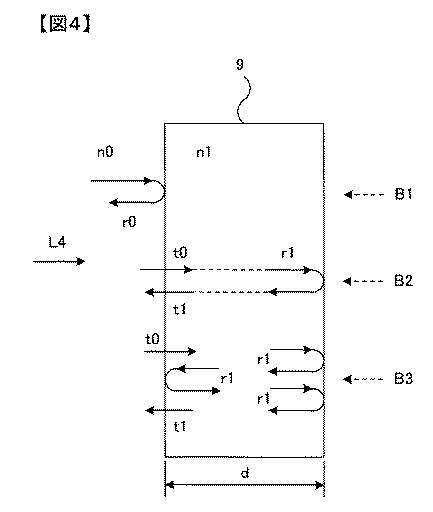
式(1)において、r0は屈折率n0の媒質から屈折率n1の試料9に入射する光が試料表面で反射される際の振幅反射率であり、次式(2)で表される。r1は試料9の内部で反射する光の振幅反射率であり、次式(3)で表される。式(2),(3)からも分かるように、r0=−r1の関係があって、試料表面での反射と試料内部での反射とは位相が反転している。
【数2】
r0=(n0−n1)/(n0+n1) …(2)
r1=(n1−n0)/(n0+n1) …(3)
【0024】
また、t0は屈折率n0の媒質から屈折率n1の試料9に入射する光の振幅透過率で、次式(4)で表される。t1は屈折率n1の試料9から屈折率n0の媒質に出射する光の振幅透過率で、次式(5)で表される。なお、式(1)において、θはθ=(ω/c)n1dであり、cは真空中の光速、dは試料9の厚さである。試料9が大気中もしくは真空中に配置されている場合には、n0=1とみなして良い。
【数3】
t0=2n0/(n0+n1) …(4)
t1=2n1/(n0+n1) …(5)
【0025】
上述したようにr0=−r1の関係があるので、式(1)は次式(6)のように書き換えることができる。
【数4】
なお、時間分解反射測定方法においては、例えば、テラヘルツ光検出素子14に入射する反射テラヘルツパルス光L5が図5(a)に示すようなものであった場合、プローブ光として入射させるパルス光L3の光路長を可動鏡16を移動して変更し、遅延時間の異なる複数のパルス光L3をテラヘルツ光検出素子14に入射させる。その結果、図5(b)に示すような電流信号Im(τ)が得られる。τはパルス光L3の光路長に対応する遅延時間である。
【0027】
図6は反射テラヘルツパルス光L5の検出動作を定性的に説明する図であり、図6(a)は図5(a)の符号Aで示す部分の拡大図、図6(c)は図5(b)の符号Aで示す部分の拡大図である。図6(b)は、プローブ光として遅延時間τ1〜τ5でテラヘルツ光検出素子14に入射する各パルス光L3(τ1)〜L3(τ5)を示したものである。図6(b)に示すようなパルス光L3(τ1)〜L3(τ5)をプローブ光としてテラヘルツ光検出素子14に入射すると、遅延時間τ1〜τ5における電流Imを検出することができる。
【0028】
例えば、パルス光L3(τ2)をテラヘルツ光検出素子14に入射すると、遅延時間τ2における電場振幅E(τ2)=E2に対応する電流Im(τ2)=Im2が検出される。同様な動作を各遅延時間τ1,τ3,τ4,τ5に関して行うことにより、図6(a)に示す電場振幅E(t)に対応して、図6(c)のような電流Im(τ)を検出することができる。
【0029】
図7は検出手順の概要を示すフローチャートである。ステップS1では、図6(b)に示したような遅延時間τi(i=1,2,3,…,n)を設定する際の添字iの値を、初期値i=0に設定する。ステップS2では、iの値をi+1で置き換えて1だけ増加する。ステップS3では、可動鏡16の位置を制御してプローブ光L3の遅延時間をτiに設定する。図7のS1→S2→S3の順に処理がされて初めてステップS3の処理が行われたときには、i=1なので遅延時間はτ1に設定される。
【0030】
ステップS4では、テラヘルツ光発生素子4にレーザパルス光を照射してテラヘルツパルス光L4を発生させる。ステップS5では、ステップS3で設定された遅延時間τiでパルス光L3をテラヘルツ光検出素子14に照射し、反射テラヘルツパルス光L5を検出する(図6参照)。ステップS6では、遅延時間τiに関する検出結果、すなわち、図6(c)のImiを読み込む。
【0031】
ステップS7では、iがnとなったか否か、すなわち、遅延時間τiで検出する反射テラヘルツパルス光L5のサンプリング数が所定数nとなったか否かを判定する。ステップS7でyesと判定されるとステップS8へ進み、noと判定されるとステップS2へ戻る。このように遅延時間を順に変えて検出することにより図3のような時系列波形をデジタル値として取得することができる。ステップS8では、取得された時系列データ(時系列波形)に基づいて、図3のパルスB1,B2,B3,…を抽出する。ステップS9では、抽出したパルスB1を参照信号とし、その他のパルスB2,B3,…を試料信号とすることにより、各種特性値を演算する。
【0032】
このように、本実施の形態における解析手法の特徴は、図3の一番目のパルスB1を、すなわち試料表面で反射されたパルスB1を参照信号として用い、それ以降のパルスB2,B3,…を試料信号として用いることにある。
【0033】
そして、試料表面で反射されたパルスB1の時系列波形のフーリエ変換と、それ以降のパルスB2,B3,…のフーリエ変換との比を位相まで含めて計算すれば良い。このようにして算出された物理量に対応する理論式は、式(6)を変形した式(7)のような形に表現される。
【数5】
上述したように、本発明では、試料表面で反射されたパルスB1を参照信号として用いているので、従来の反射測定装置のように参照用鏡を用いる必要が無く、参照用鏡の位置ずれによって位相情報が不正確になるというような不都合が生じない。すなわち、位相情報を容易に精度良く測定することが可能となる。
【0035】
また、試料9を参照用鏡に置き換えるとともに高精度に位置決めして参照信号を計測する必要がないので、測定時間の短縮を図ることができる。さらに、従来の技術で述べた装置のように試料にシリコン板等を密着配置する必要が無く、非接触測定という特徴が損なわれることもない。
【0036】
なお、上述した試料9内における多重反射とは別に、テラヘルツ光学系に多重反射の原因となる要素を含まないようにしなければならない。このようなテラヘルツパルス光の多重反射があった場合には、図3に示すような試料9で反射された反射テラヘルツパルス光L5のパルスに、光学系での多重反射によるパルスが重なって分離して解析することができなくなる可能性がある。
【0037】
例えば、テラヘルツ光発生素子4またはテラヘルツ光検出素子14に用いられるGaAs基板内部で多重反射が生じる可能性がある。このような場合には、GaAs基板内部の光路長と試料9内部の光路長とが大きく異なるように構成すれば、GaAs基板内部の多重反射によるパルスと試料9で反射されたパルスとを分離することができる。
【0038】
上述した実施の形態では、テラヘルツパルス光を用いた時間分解反射測定装置を例に説明したが、本発明はテラヘルツ帯域以外のパルス光を用いる時間分解反射測定装置にも同様に適用することができる。なお、以上説明した実施の形態と特許請求の範囲の要素との対応において、制御演算処理装置19は抽出手段および演算手段を構成する。また、本発明の特徴を損なわない限り、本発明は上記実施の形態に何ら限定されるものではない。
【0039】
【発明の効果】
以上説明したように、本発明によれば、参照用鏡等を用いた参照信号を別途測定することなく、位相情報を容易にかつ正確に測定することができる。さらに、測定時間の短縮が図れる。
【図面の簡単な説明】
【図1】本発明によるテラヘルツ時間分解反射測定装置の一実施の形態を示す図であって、装置の概略構成を模式的に示したものである。
【図2】(a)はテラヘルツ光発生素子4の斜視図であり、(b)はテラヘルツ光検出素子14の斜視図である。
【図3】反射テラヘルツパルス光L5の時系列波形を示す模式図である。
【図4】反射型の場合の反射形態を示す模式図である。
【図5】(a)は反射テラヘルツパルス光L5の電場振幅を示す図であり、(b)はテラヘルツ光検出素子14で検出される電流値Imを示す図である。
【図6】反射テラヘルツパルス光L5の検出動作を定性的に説明する図であり、(a)は図5(a)の符号Aで示す部分の拡大図、(b)は遅延時間τ1〜τ5におけるパルス光L3(τ1)〜L3(τ5)を示す図、(c)は図5(b)の符号Aで示す部分の拡大図である。
【図7】検出手順の概要を示すフローチャートである。
【符号の説明】
1 フェムト秒パルス光源
2,3,8,10,15,17 平面鏡
4 テラヘルツ光発生素子
5,13 シリコン半球レンズ
6,7,11,12 軸外し放物面鏡
9,20 試料
14 テラヘルツ光検出素子
16 可動鏡
18 駆動装置
19 制御演算処理装置[0001]
TECHNICAL FIELD OF THE INVENTION
The present invention relates to a time-resolved reflection measurement method and a terahertz time-resolved reflection measurement device for measuring by detecting pulsed light reflected by a sample.
[0002]
[Prior art]
In recent years, spectroscopic measurement and imaging technology using terahertz pulsed light have attracted attention, and a technique called terahertz time-resolved measurement is used for such measurement. In the terahertz time-resolved measurement, a sample is irradiated with terahertz pulsed light, and a transmission time-series waveform from the sample is measured in the case of a transmission type, and a reflection time-series waveform from a sample is measured in the case of a reflection type. That is, the time change of the electric field intensity of the transmitted or reflected pulse light is measured, and the amplitude intensity and phase information of the electric field for each wavelength are obtained by Fourier transform.
[0003]
Usually, in order to obtain information on samples, a time-series waveform for reference is necessary in addition to the time-series waveforms from these samples. In the case of the transmission type, a waveform detected when the sample is removed is used as the reference waveform. In the case of the reflection type, a mirror whose reflectance is regarded as 100% is provided instead of the sample. The waveform detected at that time is used. Then, the reference waveform is also subjected to Fourier transform to obtain amplitude intensity and phase information of the electric field for each wavelength. The transmittance or reflectance of the sample is determined from the ratio of the amplitude intensity of the waveform to the sample and the amplitude intensity of the reference waveform, and the phase difference can be determined from the phase of the sample and the phase of the reference waveform.
[0004]
As described above, in the terahertz time-resolved measurement, not only the transmittance and the reflectance but also the phase information of the detected light can be obtained. The effect is remarkable, for example, when obtaining the complex refractive index of the sample. The complex refractive index composed of a real part and an imaginary part plays an important role in examining the properties of a sample. However, when the phase cannot be measured, the complex refractive index cannot be obtained only from the transmittance or the reflectance.
[0005]
In the case of the transmission type, the sample position does not affect the phase. However, in the case of the reflection type, since the position of the sample affects the phase, it is necessary to arrange the sample and the reference mirror at the same position in order to use the phase information. The accuracy required at this time is about several μm at 1 THz, and higher position accuracy is required as the frequency increases.
[0006]
Thus, the positioning of the reference mirror needs to be performed with high accuracy, but generally it is difficult. In order to obtain phase information without requiring high-precision positioning, for example, a silicon plate whose physical properties are known is closely attached to the front surface of the sample (the surface on the terahertz pulse light incident side), A method of correcting a sample position so that a reflection spectrum matches a calculation result is known (for example, see Non-Patent Document 1).
[0007]
[Non-patent document 1]
Nashima, 3 others, Applied Physics Letters, (USA), December 10, 2001, Vol. 79, No. 24, p. 3923-3925
[0008]
[Problems to be solved by the invention]
However, the method in which the silicon plate is brought into close contact with the sample in this way cannot be used for any sample. In addition, since the method is a method in which a silicon plate is adhered, there is a problem that the advantage of “non-contact measurement” which is one of the features of the terahertz time-resolved measurement is impaired.
[0009]
The present invention provides a time-resolved reflection measurement method and a terahertz time-resolved reflection measurement device that can easily obtain accurate phase information.
[0010]
[Means for Solving the Problems]
The present invention is applied to a time-resolved reflection measurement method of irradiating a parallel plate sample with pulsed light, detecting the time-series waveform of reflected light from the sample and measuring the characteristics of the sample, and includes the time-series waveform of the reflected light. Measuring a characteristic of the sample based on the reference signal and the sample signal, using a reflected pulse light at the sample incident surface to be used as a reference signal, a difference signal obtained by removing the reflected pulse light from a time-series waveform of the reflected light as a sample signal. It is characterized by.
Note that the pulse light applied to the sample may be terahertz pulse light in a terahertz band.
The time-series waveform of the reflected light can be obtained by repeatedly irradiating the sample with the pulsed light and detecting the reflected light from the sample with a plurality of delay times synchronized with the pulsed light.
The present invention is applied to a terahertz time-resolved reflection measuring device that irradiates a terahertz pulse light in a terahertz band to a parallel plate sample, detects a time-series waveform of the reflected light reflected by the sample, and measures the characteristics of the sample. Extraction means for extracting the reflected pulse light at the sample incident surface from the time-series waveform of light, and calculation means for calculating a difference signal obtained by removing the reflected pulse light from the time-series waveform of the reflected light, the extraction means The characteristics of the sample are measured by using the extracted reflected pulse light as a reference signal and using the difference signal as a sample signal.
[0011]
BEST MODE FOR CARRYING OUT THE INVENTION
Hereinafter, embodiments of the present invention will be described with reference to the drawings. FIG. 1 is a view showing one embodiment of a terahertz time-resolved reflection measuring apparatus according to the present invention, and schematically shows a schematic configuration of the apparatus. In the apparatus according to the present embodiment, the femtosecond pulse light L1 emitted from the femtosecond
[0012]
In the present embodiment, the femtosecond
[0013]
One pulse light L2 split by the
[0014]
The terahertz pulse light L4 generated by the terahertz
[0015]
On the other hand, the other pulse light L3 split by the
[0016]
FIG. 2B is a diagram illustrating an example of the terahertz
[0017]
《Explanation of analysis method of reflected terahertz pulse light》
In the case of a transmission type device, the optical path length does not change even if the position of the sample is shifted in the optical axis direction, so that the position shift does not affect the phase information. On the other hand, in the case of a reflection-type device, a signal Im obtained by arranging the
[0018]
However, if the
[0019]
When measuring the reflected terahertz pulse light L5, the reflected terahertz pulse light L5 includes not only light reflected on the front surface (or the incident surface) of the
[0020]
When the reflected terahertz pulse light L5 from the
[0021]
The pulse B1 first observed in the time-series waveform shown in FIG. 3 is reflected on the surface of the
[0022]
Therefore, the complex amplitude reflectance r of the terahertz pulse light L4 incident on the
(Equation 1)
In the equation (1), r 0 is an amplitude reflectance when light incident on the
(Equation 2)
r 0 = (n 0 −n 1 ) / (n 0 + n 1 ) (2)
r 1 = (n 1 −n 0 ) / (n 0 + n 1 ) (3)
[0024]
Further, t 0 is the amplitude transmittance of light incident on the
[Equation 3]
t 0 = 2n 0 / (n 0 + n 1 ) (4)
t 1 = 2n 1 / (n 0 + n 1 ) (5)
[0025]
Since there is a relationship of r 0 = −r 1 as described above, the equation (1) can be rewritten as the following equation (6).
(Equation 4)
In the time-resolved reflection measurement method, for example, when the reflected terahertz pulse light L5 incident on the terahertz
[0027]
6A and 6B are diagrams for qualitatively explaining the detection operation of the reflected terahertz pulse light L5. FIG. 6A is an enlarged view of a portion indicated by a symbol A in FIG. 5A, and FIG. It is an enlarged view of the part shown with the code | symbol A of (b). FIG. 6B shows pulsed light beams L3 (τ1) to L3 (τ5) incident on the terahertz
[0028]
For example, when the pulse light L3 (τ2) is incident on the terahertz
[0029]
FIG. 7 is a flowchart showing an outline of the detection procedure. In step S1, the value of the subscript i when setting the delay time τi (i = 1, 2, 3,..., N) as shown in FIG. 6B is set to the initial value i = 0. In step S2, the value of i is replaced with i + 1 and increased by one. In step S3, the position of the
[0030]
In step S4, the terahertz
[0031]
In step S7, it is determined whether or not i has become n, that is, whether or not the number of samples of the reflected terahertz pulse light L5 detected at the delay time τi has reached a predetermined number n. If “yes” is determined in step S7, the process proceeds to step S8, and if “no” is determined, the process returns to step S2. As described above, the time series waveform as shown in FIG. 3 can be obtained as a digital value by sequentially changing the delay time and detecting. In step S8, the pulses B1, B2, B3,... Of FIG. 3 are extracted based on the acquired time-series data (time-series waveform). In step S9, various characteristic values are calculated by using the extracted pulse B1 as a reference signal and the other pulses B2, B3,... As sample signals.
[0032]
As described above, the feature of the analysis method according to the present embodiment is that the first pulse B1 in FIG. 3, that is, the pulse B1 reflected on the sample surface is used as a reference signal, and the subsequent pulses B2, B3,. It is used as a sample signal.
[0033]
Then, the ratio between the Fourier transform of the time-series waveform of the pulse B1 reflected on the sample surface and the Fourier transform of the subsequent pulses B2, B3,... The theoretical expression corresponding to the physical quantity calculated in this manner is expressed in a form like Expression (7) obtained by modifying Expression (6).
(Equation 5)
As described above, in the present invention, since the pulse B1 reflected on the sample surface is used as a reference signal, there is no need to use a reference mirror as in a conventional reflection measurement device, and the position of the reference mirror is shifted due to the displacement of the reference mirror. There is no inconvenience such as inaccurate phase information. That is, it is possible to easily and accurately measure the phase information.
[0035]
Further, since it is not necessary to replace the
[0036]
Note that, apart from the multiple reflection in the
[0037]
For example, multiple reflection may occur inside the GaAs substrate used for the terahertz
[0038]
In the above-described embodiment, the time-resolved reflection measurement device using terahertz pulse light has been described as an example, but the present invention can be similarly applied to a time-resolved reflection measurement device using pulse light outside the terahertz band. . In the correspondence between the embodiment described above and the elements of the claims, the control
[0039]
【The invention's effect】
As described above, according to the present invention, phase information can be easily and accurately measured without separately measuring a reference signal using a reference mirror or the like. Further, the measurement time can be reduced.
[Brief description of the drawings]
FIG. 1 is a view showing one embodiment of a terahertz time-resolved reflection measuring apparatus according to the present invention, and schematically shows a schematic configuration of the apparatus.
2A is a perspective view of a terahertz
FIG. 3 is a schematic diagram showing a time-series waveform of reflected terahertz pulse light L5.
FIG. 4 is a schematic diagram showing a reflection mode in the case of a reflection type.
5A is a diagram illustrating an electric field amplitude of the reflected terahertz pulse light L5, and FIG. 5B is a diagram illustrating a current value Im detected by the terahertz
FIGS. 6A and 6B are diagrams qualitatively illustrating a detection operation of the reflected terahertz pulse light L5, where FIG. 6A is an enlarged view of a portion indicated by a symbol A in FIG. 5A and FIG. FIG. 5C is a view showing pulsed light L3 (τ1) to L3 (τ5), and FIG. 5C is an enlarged view of a portion indicated by reference numeral A in FIG.
FIG. 7 is a flowchart showing an outline of a detection procedure.
[Explanation of symbols]
1 Femtosecond pulse
Claims (4)
前記反射光の時系列波形に含まれる前記試料入射面での反射パルス光を参照信号とし、前記反射光の時系列波形から前記反射パルス光を除いた差分信号を試料信号とし、前記参照信号および前記試料信号に基づいて前記試料の特性を測定することを特徴とする時間分解反射測定方法。In a time-resolved reflection measuring method of irradiating a parallel plate sample with pulsed light and detecting a time-series waveform of reflected light from the sample to measure characteristics of the sample,
The reflected pulse light at the sample incident surface included in the time series waveform of the reflected light as a reference signal, a difference signal obtained by removing the reflected pulse light from the time series waveform of the reflected light as a sample signal, the reference signal and A time-resolved reflection measurement method, wherein characteristics of the sample are measured based on the sample signal.
前記試料に照射するパルス光を、テラヘルツ帯域のテラヘルツパルス光としたことを特徴とする時間分解反射測定法。In the time-resolved reflection measurement method according to claim 1,
A time-resolved reflection measurement method, wherein the pulse light applied to the sample is a terahertz pulse light in a terahertz band.
前記試料にパルス光を繰り返し照射するとともに、前記パルス光と同期した複数の遅延時間で前記試料からの反射光をそれぞれ検出して前記時系列波形を検出する検出工程と、
前記検出工程で検出された時系列波形から前記参照信号および前記試料信号を抽出する抽出工程とを有することを特徴とする時間分解反射測定法。The time-resolved reflection measurement method according to claim 1 or 2,
While repeatedly irradiating the sample with pulsed light, a detecting step of detecting the reflected light from the sample with a plurality of delay times synchronized with the pulsed light and detecting the time-series waveform,
An extraction step of extracting the reference signal and the sample signal from the time-series waveform detected in the detection step.
前記反射光の時系列波形から前記試料入射面での反射パルス光を抽出する抽出手段と、
前記反射光の時系列波形から前記反射パルス光を除いた差分信号を演算する演算手段とを備え、
前記抽出手段で抽出された前記反射パルス光を参照信号に用いるとともに前記差分信号を試料信号に用いて、前記試料の特性を測定することを特徴とするテラヘルツ時間分解反射測定装置。In a terahertz time-resolved reflection measurement device that irradiates a terahertz pulse light in a terahertz band to a parallel plate sample, detects a time-series waveform of reflected light reflected by the sample, and measures characteristics of the sample,
Extraction means for extracting reflected pulse light at the sample incident surface from the time-series waveform of the reflected light,
Computing means for computing a difference signal obtained by removing the reflected pulse light from the time-series waveform of the reflected light,
A terahertz time-resolved reflection measuring apparatus, wherein the characteristics of the sample are measured by using the reflected pulse light extracted by the extracting means as a reference signal and using the difference signal as a sample signal.
Priority Applications (1)
| Application Number | Priority Date | Filing Date | Title |
|---|---|---|---|
| JP2002366951A JP2004198250A (en) | 2002-12-18 | 2002-12-18 | Time-resolved reflection measuring method and terahertz time-resolved reflection measuring apparatus |
Applications Claiming Priority (1)
| Application Number | Priority Date | Filing Date | Title |
|---|---|---|---|
| JP2002366951A JP2004198250A (en) | 2002-12-18 | 2002-12-18 | Time-resolved reflection measuring method and terahertz time-resolved reflection measuring apparatus |
Publications (1)
| Publication Number | Publication Date |
|---|---|
| JP2004198250A true JP2004198250A (en) | 2004-07-15 |
Family
ID=32764002
Family Applications (1)
| Application Number | Title | Priority Date | Filing Date |
|---|---|---|---|
| JP2002366951A Pending JP2004198250A (en) | 2002-12-18 | 2002-12-18 | Time-resolved reflection measuring method and terahertz time-resolved reflection measuring apparatus |
Country Status (1)
| Country | Link |
|---|---|
| JP (1) | JP2004198250A (en) |
Cited By (8)
| Publication number | Priority date | Publication date | Assignee | Title |
|---|---|---|---|---|
| JP2008039422A (en) * | 2006-08-01 | 2008-02-21 | Nissan Motor Co Ltd | Object identification method and device |
| WO2010044193A1 (en) * | 2008-10-14 | 2010-04-22 | 国立大学法人東北大学 | Sample analysis method |
| DE102006042642B4 (en) * | 2006-09-12 | 2010-06-24 | Batop Gmbh | Terahertz time-domain spectrometer |
| JP2011021930A (en) * | 2009-07-14 | 2011-02-03 | Nissan Motor Co Ltd | Waveform observation apparatus and method |
| DE102010032382A1 (en) | 2010-07-27 | 2012-02-02 | Batop Gmbh | Fiber-coupled terahertz time domain spectrometer has pulse laser that uses transmitting antenna and receiving antenna, where both antennas are assigned with collimating terahertz optics in each case |
| CN103076107A (en) * | 2013-01-17 | 2013-05-01 | 杭州电子科技大学 | Terahertz pulse measurement-based burning temperature sensing device and method |
| US8710440B2 (en) | 2010-02-08 | 2014-04-29 | National University Corporation Okayama University | Measuring device and measuring method that use pulsed electromagnetic wave |
| JP2015508160A (en) * | 2012-02-08 | 2015-03-16 | ハネウェル・アスカ・インコーポレーテッド | Caliper coating measurement on web with continuous non-uniformity using THZ sensor |
-
2002
- 2002-12-18 JP JP2002366951A patent/JP2004198250A/en active Pending
Cited By (11)
| Publication number | Priority date | Publication date | Assignee | Title |
|---|---|---|---|---|
| JP2008039422A (en) * | 2006-08-01 | 2008-02-21 | Nissan Motor Co Ltd | Object identification method and device |
| DE102006042642B4 (en) * | 2006-09-12 | 2010-06-24 | Batop Gmbh | Terahertz time-domain spectrometer |
| WO2010044193A1 (en) * | 2008-10-14 | 2010-04-22 | 国立大学法人東北大学 | Sample analysis method |
| JP5028529B2 (en) * | 2008-10-14 | 2012-09-19 | 国立大学法人東北大学 | Sample analysis method |
| US8514403B2 (en) | 2008-10-14 | 2013-08-20 | Tohoku University | Sample analysis method |
| JP2011021930A (en) * | 2009-07-14 | 2011-02-03 | Nissan Motor Co Ltd | Waveform observation apparatus and method |
| US8710440B2 (en) | 2010-02-08 | 2014-04-29 | National University Corporation Okayama University | Measuring device and measuring method that use pulsed electromagnetic wave |
| DE102010032382A1 (en) | 2010-07-27 | 2012-02-02 | Batop Gmbh | Fiber-coupled terahertz time domain spectrometer has pulse laser that uses transmitting antenna and receiving antenna, where both antennas are assigned with collimating terahertz optics in each case |
| JP2015508160A (en) * | 2012-02-08 | 2015-03-16 | ハネウェル・アスカ・インコーポレーテッド | Caliper coating measurement on web with continuous non-uniformity using THZ sensor |
| CN103076107A (en) * | 2013-01-17 | 2013-05-01 | 杭州电子科技大学 | Terahertz pulse measurement-based burning temperature sensing device and method |
| CN103076107B (en) * | 2013-01-17 | 2014-12-24 | 杭州电子科技大学 | Terahertz pulse measurement-based burning temperature sensing device and method |
Similar Documents
| Publication | Publication Date | Title |
|---|---|---|
| US7214940B2 (en) | Apparatus and method for investigating a sample | |
| JP4862164B2 (en) | Pulse laser beam timing adjustment device, adjustment method, and optical microscope | |
| JP6245600B2 (en) | Polarization sensitive terahertz wave detector | |
| JP6654948B2 (en) | Method and apparatus for measuring pulse light waveform | |
| WO2016132452A1 (en) | Terahertz wave measurement device, terahertz wave measurement method, and computer program | |
| US11867620B2 (en) | Ultrafast chemical imaging by widefield photothermal sensing of infrared absorption | |
| JP2004198250A (en) | Time-resolved reflection measuring method and terahertz time-resolved reflection measuring apparatus | |
| TWI798614B (en) | Combined ocd and photoreflectance apparatus, system and method | |
| CN109186769B (en) | A method of the measurement ellipse inclined rate of chirped pulse | |
| JPH0694605A (en) | Spectral photographing device using pulse electromagnetic wave source and interferometer | |
| US7295325B2 (en) | Time-resolved measurement technique using radiation pulses | |
| CN105115940B (en) | Optical material refractive index curve measuring method and device | |
| WO2004113885A1 (en) | Optical waveform measurement device and measurement method thereof, complex refractive index measurement device and measurement method thereof, and computer program recording medium containing the program | |
| JP2002303574A (en) | Terahertz optical device and its adjusting method | |
| JP2004020352A (en) | Method and apparatus for measuring terahertz pulse light | |
| JP3533651B1 (en) | Time-resolved nonlinear susceptibility measurement system | |
| JP5127159B2 (en) | Measuring apparatus and measuring method | |
| JP2009150811A (en) | Terahertz spectroscopic device | |
| JP2012208098A (en) | Physical property measuring device and physical property measuring method | |
| EP2078184B1 (en) | Method for correcting a wave front analyser and analyser implementing said method | |
| JP2006300808A (en) | Raman spectrometry system | |
| KR102194321B1 (en) | Continuously measurable spectroscopic ellipsometer | |
| JP2767000B2 (en) | Waveguide dispersion measurement method and apparatus | |
| JP6941004B2 (en) | Tunnel current controller and tunnel current control method | |
| WO2001040773A2 (en) | System and method for frequency domain interferometric second harmonic spectroscopy |
Legal Events
| Date | Code | Title | Description |
|---|---|---|---|
| A621 | Written request for application examination |
Free format text: JAPANESE INTERMEDIATE CODE: A621 Effective date: 20051019 |
|
| A977 | Report on retrieval |
Free format text: JAPANESE INTERMEDIATE CODE: A971007 Effective date: 20070605 |
|
| A131 | Notification of reasons for refusal |
Free format text: JAPANESE INTERMEDIATE CODE: A131 Effective date: 20070612 |
|
| A131 | Notification of reasons for refusal |
Free format text: JAPANESE INTERMEDIATE CODE: A131 Effective date: 20071016 |
|
| A02 | Decision of refusal |
Free format text: JAPANESE INTERMEDIATE CODE: A02 Effective date: 20080304 |