JP2004196183A - On-vehicle equipment control system - Google Patents
On-vehicle equipment control system Download PDFInfo
- Publication number
- JP2004196183A JP2004196183A JP2002368906A JP2002368906A JP2004196183A JP 2004196183 A JP2004196183 A JP 2004196183A JP 2002368906 A JP2002368906 A JP 2002368906A JP 2002368906 A JP2002368906 A JP 2002368906A JP 2004196183 A JP2004196183 A JP 2004196183A
- Authority
- JP
- Japan
- Prior art keywords
- vehicle
- type information
- type
- control system
- output
- Prior art date
- Legal status (The legal status is an assumption and is not a legal conclusion. Google has not performed a legal analysis and makes no representation as to the accuracy of the status listed.)
- Pending
Links
- 230000008859 change Effects 0.000 abstract description 2
- 238000000034 method Methods 0.000 description 9
- 230000008569 process Effects 0.000 description 9
- 239000003086 colorant Substances 0.000 description 4
- 238000010586 diagram Methods 0.000 description 3
- 230000004913 activation Effects 0.000 description 2
- 238000013500 data storage Methods 0.000 description 2
- 238000001514 detection method Methods 0.000 description 2
- 230000003213 activating effect Effects 0.000 description 1
- 239000004973 liquid crystal related substance Substances 0.000 description 1
- 238000004519 manufacturing process Methods 0.000 description 1
- 238000012986 modification Methods 0.000 description 1
- 230000004048 modification Effects 0.000 description 1
- 230000005236 sound signal Effects 0.000 description 1
- 230000000007 visual effect Effects 0.000 description 1
Images


Classifications
-
- G—PHYSICS
- G01—MEASURING; TESTING
- G01C—MEASURING DISTANCES, LEVELS OR BEARINGS; SURVEYING; NAVIGATION; GYROSCOPIC INSTRUMENTS; PHOTOGRAMMETRY OR VIDEOGRAMMETRY
- G01C21/00—Navigation; Navigational instruments not provided for in groups G01C1/00 - G01C19/00
- G01C21/26—Navigation; Navigational instruments not provided for in groups G01C1/00 - G01C19/00 specially adapted for navigation in a road network
Abstract
Description
【0001】
【発明の属する技術分野】
本発明は、搭載される車両の種別に応じて、車載機器における動作態様を切り換えることが可能な車載機器制御システムに関するものである。
【0002】
【従来の技術】
例えば、特許文献1には、搭載される車両の種類に応じて、表示装置においてタッチスイッチとして表示される操作スイッチを切り換える車両用表示装置が開示されている。
【0003】
この車両用表示装置1は、図4に示すように、表示器であるLCDパネル3における描画処理を制御するメイン処理部6と、LCDパネル3上に形成したタッチスイッチ群4及びLCDパネル3の周囲に形成した操作パネル5からの操作信号の入出力処理を制御するスイッチ制御部7とを備えている。そして、メイン処理部6は、搭載対象の全車種について共通する内容の共通プログラムと各車種のための固有の内容の固有プログラム群とにより構成した制御プログラムを記憶している。一方、スイッチ制御部7は、操作信号の入出力処理などのためのプログラムの他に、搭載対象の車両種類を示す車種コードを記憶する。メイン処理部6は、例えば、エアコンスイッチが操作されたとき、スイッチ制御部7から車種コードを取得して、その車種コードに対応したエアコンの操作画面を表示する。つまり、メイン処理部6は、記憶した固有プログラム群のうちスイッチ制御部7から取得した車種コードに対応したプログラムを有効化することにより、車種コードに対応した操作スイッチをLCDパネル3に表示する。
【0004】
この従来の車両用表示装置1によれば、メイン処理部6における制御プログラムを搭載する車両種別に係わらず、共通して使用することができる。そのため、搭載対象の車種毎に異なるプログラムを用意する必要がなくなり、ソフト開発のための負担を軽減できるようになる。
【0005】
【特許文献1】
特開2001−306330号
【0006】
【発明が解決しようとする課題】
しかしながら、上述した従来の車両用表示装置1は、操作パネル5が車両種別毎に専用のものが用いられる。従って、スイッチ制御部7も、その操作パネル5からの操作信号の入出力処理を行なうプログラムとして、それぞれ車両種別毎に専用のプログラムを用意する必要がある。さらに、従来の車両用表示装置1は、車両の種類を示す車種コードをスイッチ制御部7が記憶する構成を採用しているので、仮に操作パネル5及びその入出力処理のためのプログラムを共通化したとしても、スイッチ制御部7は車種毎に異なるものとなってしまう。
【0007】
本発明は、上記の点に鑑みてなされたもので、車両用表示装置等の車載機器を搭載される車両種別に係わらず、普遍的に共通使用することが可能な車載機器制御システムを提供することを目的とするものである。
【0008】
【課題を解決するための手段】
上記目的を達成するために、請求項1に記載の車載機器制御システムは、少なくとも車両の種別を示す種別情報を記憶するとともに、所定のタイミングにおいて、その種別情報を出力する出力手段と、
出力手段に接続され、出力手段が出力する種別情報を他の車載機器に伝達するネットワーク手段と、
車両の種別毎に設定すべき仕様を記憶するとともに、ネットワーク手段を介して、出力手段から出力される車両の種別情報を取得したとき、その種別情報に対応する仕様を抽出し、その仕様に従って動作態様が設定される車載機器とを備えることを特徴とする。
【0009】
このように、請求項1に記載の車載機器制御システムでは、車両の種別を示す種別情報を記憶する出力手段と車載機器とをネットワーク手段を介して接続し、車載機器は、その出力手段から種別情報を取得するように構成した。従って、車載機器は、その出力手段から取得した種別情報に基づいて、車種に応じた仕様に動作態様を設定することができる。このように、車種に応じた動作態様で動作することを可能としながら、車載機器に関しては、ハード面およびソフト面に関し何ら変更を加えることなく、各種の車両に対して共通使用することができる。この結果、車載機器の製造、開発コストを大幅に減少することができる。
【0010】
請求項2に記載の車載機器制御システムでは、車載機器は、複数のスイッチからなる操作手段を備え、当該操作手段における複数のスイッチの操作により各種の機能が実行されるものであり、車載機器は、車両の種別毎に設定すべき仕様として、複数のスイッチに割り当てる機能を記憶しており、車両の種別情報に基づいて、該当する種別の車両において実行すべき機能を操作手段における複数のスイッチに割り当てることを特徴とする。複数のスイッチとしては、予め車載機器の周辺に設置されたり、請求項3に記載したように、ステアリングホイールに設置されたメカニカルなスイッチや、表示装置と一体となって、表示画面に操作スイッチが表示されるタッチパネル方式のスイッチが該当する。特に、予め車載機器の周辺やステアリングホイールに設置されたスイッチに対して、そのスイッチが操作されたときに実行される機能を車両の種別情報に対応して切り換えるようにすれば、従来技術のように操作パネルやスイッチ制御部を車種ごとに専用のものを用意することが不要とできる。
【0011】
請求項4に記載したように、出力手段は、車両が始動される毎に、車両の種別情報を出力することが好ましい。車両の使用開始のできる限り早い時点で、車両の種別に対応した動作態様にて動作を開始することを可能にするためである。
【0012】
請求項5に記載したように、車載機器は、車両の始動時に出力手段から車両の種別情報が取得できない場合、予め定めたデフォルトデータに従って、動作態様を設定することが好ましい。これにより、ネットワーク手段等に何らかの障害が発生して、車載機器が種別情報を取得できない場合であっても、車載機器を動作可能にすることができる。
【0013】
請求項6に記載したように、車載機器は、設定された動作態様を記憶し、車両の始動時に出力手段から車両の種別情報が取得できない場合は、記憶した動作態様にて動作を行なうように構成しても良い。これにより、車載機器が何らかの原因で種別情報が取得できない場合であっても、正常に種別情報を取得できた場合と同様の動作態様にて車載機器を作動させることができる。
【0014】
請求項7に記載したように、車載機器は、出力手段から出力された車両の種別コードが記憶した車両の種別のいずれにも該当しない場合、その動作を停止するように構成しても良い。予め搭載することが予定されている車種以外の車両に車載機器が搭載された場合には、盗難等の不正が行なわれたことが考えられるためである。なお、出力手段が、車両の種別情報とともに、車両の車台番号等の固有情報を出力する場合には、その固有情報を記憶しておき、新たに取得した固有情報が記憶固有情報と異なるときに、車載機器の動作を停止するようにしても良い。
【0015】
【発明の実施の形態】
以下、本発明の実施の形態における車載機器制御システムに関して、図面に基づいて説明する。なお、本実施形態では、車載機器としてオーディオ制御部を有するナビゲーション装置を採用した例について説明する。
【0016】
図1は、本実施形態における車載機器制御システムの全体の構成を示すブロック図である。同図に示すように、ナビゲーション装置100は、ナビゲーション制御部120、表示装置130、及びオーディオ制御部140から構成されている。このナビゲーション装置100は、車内ローカルエリアネットワーク(LAN)を介して、他の車載機器であるマスタECU200、ステアリングスイッチ300、オーディオアンプ400等と接続されている。
【0017】
ナビゲーション制御部120は、図示していないが、車両の現在位置を検出する位置検出器や、地図データを格納する地図データ格納器等を備えている。そして、ナビゲーション制御部120は、位置検出器による現在位置データ及び地図データ格納器からの地図データに基づいて、表示装置130に車両の現在位置を示す自車両マークとともに周辺の地図を表示する。また、目的地が設定された場合には、その目的地までの経路を表示して、経路案内を行なうものである。
【0018】
表示装置130は、例えば、液晶ディスプレイによって構成される。この表示装置130は、表示画面に操作スイッチを表示した際に、その操作スイッチの表示領域への接触を検出する検出部(図示せず)を内蔵している。この検出部は、よく知られているように、例えば、画面の周囲に設けられる複数の受発光器や感圧フィルム等によって構成される。このように、表示装置130は、タッチパネル方式のディスプレイとなっており、各種の入力に使用される。
【0019】
オーディオ制御部140は、図示していないが、CDプレーヤー、テレビチューナー、ラジオチューナー等、各種のオーディオ機器を備えている。そして、オーディオ制御部140は、通常のコンピュータを主要部として構成されており、内部には周知のCPU、ROM、RAM、I/O及びこれらの構成を接続するバスラインが備えられている。ROMには、オーディオ制御部120が実行する制御プログラムが書き込まれており、オーディオ制御部120は、その制御プログラムに従って、例えば表示装置130に各種のオーディオ機器の操作スイッチを表示したり、各種のオーディオ機器からのオーディオ・ビジュアル信号を、オーディオアンプ400や表示装置130に出力する。
【0020】
さらに、オーディオ制御部140のROMには、後述するマスタECU200から搭載車両の車種情報を含む車両IDを取得し、その車種情報に応じて、ステアリングスイッチ等の設定を行なうプログラム、及び車種情報とステアリングスイッチが実行する機能等との対応関係を示すマップも書き込まれている。
【0021】
マスタECU200は、車両に搭載された各種の車載機器の作動を制御するものであり、イグニッションスイッチ(IGSW)からの信号を入力している。そして、IGSW信号により、アクセサリースイッチやイグニッションがオンされたことを検出すると、車内LANを介して各種の車載機器に起動信号を出力する。この起動信号を出力後、マスタECU200は、車両の製造メーカー、車両の種別、車台番号等の情報からなるID信号を各種の車載機器に向けて出力する。
【0022】
ステアリングスイッチ300は、図示しないステアリングホイールのハブ部に設置されるものであり、本実施形態では、6個のスイッチSW1〜SW6が設けられる。これらのステアリングスイッチ300は、例えば、一般的なプッシュスイッチとして構成されるものである。
【0023】
オーディオアンプ400は、上述したオーディオ制御部140からのオーディオ信号を増幅して、スピーカ410に出力する。
【0024】
次に、本実施形態における車載機器制御システムの特徴に関する、車種情報に応じたステアリングスイッチ300の設定や表示装置130における初期画面等の設定を行なう処理について説明する。
【0025】
例えば、ナビゲーション装置100が起動されるとき、表示画面には地図が表示されるまでの期間、予め定めた初期画面を表示する場合がある。この初期画面には、例えばその車両を製造したメーカー名やその車両のモデル名等を表示することが好まれる。
【0026】
また、ユーザの操作性を考慮して、例えばオーディオ機器の操作スイッチをステアリングホイールに設置することがあるが、その操作スイッチにより実行される機能は車種毎に異なることが一般的である。
【0027】
本実施形態による車載機器制御システムでは、このような車種ごとのカスタマイズの要求を満たしながら、同様の車載機器を複数種類の車両に共通使用することを可能とするものである。
【0028】
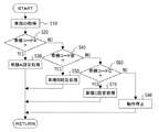
図2は、車種情報に応じたステアリングスイッチ300の設定や表示装置130における初期画面等の設定を行なう処理を示すフローチャートである。なお、このフローチャートに示す処理は、車載機器制御システムにおけるオーディオ制御部140にて実行される。
【0029】
図2のステップS10では、マスタECU200から出力された車両ID信号を取得する。この車両ID信号は、上述したように、起動信号が出力された直後にマスタECU200から出力されるものである。
【0030】
ステップS20では、その車両ID信号に含まれる車種情報が、車種コードAに該当するものであるか否かが判別される。このとき、車種情報が車種コードAに該当すると判別されると、ステップS30にて、車種Aの設定処理を実施する。一方、ステップS20において、車両ID信号に含まれる車種情報が、車種コードAに該当しないと判別されると、ステップS40に進んで、車種コードBに該当するか否かが判別される。車種コードBに該当すると判別されると、ステップS50にて、車種Bの設定処理を実施する。同様に、ステップS70では車両ID信号に含まれる車種情報が車種コードCに該当するか否かが判別され、該当する場合には、ステップS70にて車種Cの設定処理を実施する。
【0031】
なお、ステップS20、S40,S60の処理により、車両ID信号に含まれる車種情報がいずれの車種コードにも該当しないと判別されると、ステップS80にて、車載機器であるナビゲーション装置100の動作を停止する。本実施形態においては、ナビゲーション装置100は、車種コードA〜Cのいずれかの車両に搭載されることが予定されるものである。このような場合に、ステップS20,S40,S60の処理により、予め搭載することが予定されている車種以外の車両に搭載されたと判別された場合には、盗難等の不正な行為が行なわれたとも考えられるため、ナビゲーション装置100の動作を停止させるのである。
【0032】
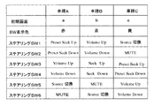
上記のフローチャートに示す処理により、車両ID信号に含まれる車種情報がいずれかの車種コードに該当した場合、その車種コードに応じた仕様への設定処理が行なわれる。この設定処理を図3のマップに基づいて説明する。
【0033】
図3は、車種コードに応じた各種の仕様、すなわち、6個のステアリングスイッチSW1〜SW6に割り当てるべき機能、選択すべき初期画面、及び表示装置130に表示される操作スイッチの表示色を示すマップである。
【0034】
このマップに示すように、車種コードAの車両であると判別された場合には、初期画面として、その車種Aの製造メーカー名及びモデル名を表示する初期画面aが選択される。さらに、操作スイッチの表示色としては、初期画面の背景色と同系統の赤色が選択される。また、6個のステアリングスイッチSW1〜SW6に関しては、ステアリングスイッチSW1には、プリセットシークアップ(Preset Seek Up)機能が割り当てられる。このプリセットシークアップ機能は、現在選局しているラジオ放送局の周波数を、初期設定として予め選局され記憶されているラジオ放送局の周波数まで増加させるものである。ステアリングスイッチSW2には、プリセットシークダウン(Preset Seek Down)機能が割り当てられる。これは、プリセットシークアップ機能とは逆に、予め記憶されているラジオ放送局の周波数まで周波数を減少させるものである。また、ステアリングスイッチSW3にはボリュームアップ(Volume Up)機能が割り当てられ、ステアリングスイッチSW4にはボリュームダウン(Volume Down)機能が割り当てられる。従って、これらのステアリングスイッチSW3、SW4によって選択しているオーディオ機器の音量の調節を行なうことができる。ステアリングスイッチSW5にはソース(Source)切換機能が割り当てられ、このスイッチを操作することにより、動作するオーディオ機器が所定の順番で切り換えられる。そして、ステアリングスイッチSW6にはミュート(MUTE)機能が割り当てられる。従って、このスイッチを操作することにより、オーディオ音声を一時的に消去することができる。
【0035】
車両ID信号に含まれる車種情報により、車種Bもしくは車種Cに対応する仕様の設定を行なう場合にも、上述した車種Aの場合と同様に、図3に示すマップを参照しつつ、ナビゲーション装置100の初期画面及び操作スイッチの表示色を選択するとともに、ステアリングスイッチSW1〜SW6に所定の機能を割り当てる。
【0036】
なお、ステアリングスイッチSW1〜SW6に割り当てる機能は、上述した例に制限されるものではなく、各種オーディオ機器を操作するための全ての機能が対象になりえる。
【0037】
上述したように、本実施形態における車載機器制御システムにおいては、各車両の種別毎に、ステアリングスイッチに設定すべき機能等をマップとして記憶しておき、かつ、車種情報は車内LANを介して取得する。このため、搭載される車種毎に仕様を変更することを可能としながら、車載機器であるナビゲーション装置に対してはなんら変更を加えることなく、複数種類の車両に共通使用することが可能となるのである。
【0038】
なお、本発明は上述した実施形態に制限されることなく、種々変更して実施することが可能である。
【0039】
例えば、上述した実施形態においては、ステアリングスイッチSW1〜SW6に割り当てる機能を車種毎に変更したが、表示装置130に表示される表示スイッチの種類についても、同様に車種毎に変更するようにしても良い。さらに、車載機器が実行可能な機能そのものを、車種毎に設定するようにしても良い。また、上述した実施形態においては、本発明をオーディオ制御部を内蔵したナビゲーション装置に適用した例について説明したが、車載機器としては、ナビゲーション装置に限られることなく、車両に搭載される制御機器であれば、本発明を適用することが可能である。
【0040】
上述した実施形態においては、マスタECU200から車両ID信号が出力され、ナビゲーション装置100がその車両ID信号を正常に取得したことを前提として説明を行なった。しかしながら、ナビゲーション装置100は、車内LANやマスタECU200に何らかの障害が発生した場合、車両ID信号を正常に取得することができないことも考えられる。このため、ナビゲーション装置100は、上述した初期画面や操作スイッチの表示色、及び各ステアリングスイッチSW1〜SW6に割り当てるデフォルトデータを設定しておき、車両ID信号を取得できない場合には、そのデフォルトデータに従って、設定を行なうこととしても良い。
【0041】
また、過去に、車両ID信号が取得でき、車両の種別に応じた設定がなされた場合には、その設定内容を記憶し、車両の始動時に車両ID信号が取得できない場合は、記憶した設定内容にて動作するようにしても良い。このようにすれば、正常に車両ID信号を取得できた場合と同様の設定内容にて、ナビゲーション装置100を動作させることができる。
【0042】
さらに、上述した実施形態では、車両ID信号に含まれる車種情報が、搭載されることが予定されているいずれの車種にも該当しない場合、ナビゲーション装置100の動作を停止することとした。しかしながら、上述した実施形態のように、マスタECU200が車両ID信号として車台番号等の各車両に固有な固有情報も出力する場合には、車両ID信号を取得したときに、その固有情報を記憶しておき、新たに取得した固有情報が記憶固有情報と異なるときに、ナビゲーション装置100の動作を停止するようにしても良い。
【図面の簡単な説明】
【図1】実施形態に係わる、車載機器制御システムの全体構成を示す概念図である。
【図2】車種情報に応じたステアリングスイッチの設定や表示装置における初期画面等の設定を行なう処理を示すフローチャートである。
【図3】車種コードに応じて6個のステアリングスイッチSW1〜SW6に割り当てるべき機能、選択すべき初期画面、及び表示装置表示される操作スイッチの表示色を示すマップである。
【図4】従来の車両用表示装置の構成を示す構成図である。
【符号の説明】
100 ナビゲーション装置
120 ナビゲーション制御部
130 表示装置
140 オーディオ制御部
200 マスタECU
300 ステアリングスイッチ
400 オーディオアンプ[0001]
TECHNICAL FIELD OF THE INVENTION
The present invention relates to an on-vehicle device control system capable of switching operation modes of on-vehicle devices according to the type of a vehicle to be mounted.
[0002]
[Prior art]
For example, Patent Literature 1 discloses a vehicular display device that switches an operation switch displayed as a touch switch on a display device according to the type of a vehicle to be mounted.
[0003]
As shown in FIG. 4, the vehicle display device 1 includes a
[0004]
According to this conventional vehicle display device 1, it can be commonly used regardless of the type of vehicle in which the control program in the
[0005]
[Patent Document 1]
JP-A-2001-306330
[Problems to be solved by the invention]
However, in the above-described conventional vehicle display device 1, the
[0007]
The present invention has been made in view of the above points, and provides an in-vehicle device control system that can be universally used irrespective of the type of vehicle in which the in-vehicle device such as a vehicle display device is mounted. It is intended for that purpose.
[0008]
[Means for Solving the Problems]
To achieve the above object, the on-vehicle device control system according to claim 1 stores at least type information indicating a type of a vehicle, and at a predetermined timing, an output unit that outputs the type information,
A network unit connected to the output unit and transmitting the type information output by the output unit to another vehicle-mounted device;
In addition to storing specifications to be set for each type of vehicle, when the type information of the vehicle output from the output means is obtained via the network means, the specification corresponding to the type information is extracted, and operation is performed according to the specification. And a vehicle-mounted device in which the mode is set.
[0009]
As described above, in the on-vehicle device control system according to the first aspect, the output means for storing the type information indicating the type of the vehicle and the on-vehicle device are connected via the network means, and the on-vehicle device receives the type information from the output means. It was configured to acquire information. Therefore, the in-vehicle device can set the operation mode to the specification according to the vehicle type based on the type information acquired from the output unit. As described above, the in-vehicle device can be commonly used for various vehicles without making any change in hardware and software, while enabling operation in an operation mode corresponding to the vehicle type. As a result, the manufacturing and development costs of the in-vehicle equipment can be significantly reduced.
[0010]
In the in-vehicle device control system according to claim 2, the in-vehicle device includes an operation unit including a plurality of switches, and various functions are executed by operating a plurality of switches in the operation unit. A function to be assigned to a plurality of switches is stored as a specification to be set for each type of vehicle, and a function to be executed in the vehicle of the corresponding type is stored in a plurality of switches in the operation means based on the type information of the vehicle. It is characterized by assigning. As the plurality of switches, the switches are installed in advance around the on-vehicle equipment, as described in
[0011]
Preferably, the output means outputs the type information of the vehicle every time the vehicle is started. This is to enable the operation to be started in an operation mode corresponding to the type of the vehicle as soon as possible after the start of use of the vehicle.
[0012]
As described in
[0013]
As described in
[0014]
As described in
[0015]
BEST MODE FOR CARRYING OUT THE INVENTION
Hereinafter, a vehicle-mounted device control system according to an embodiment of the present invention will be described with reference to the drawings. In this embodiment, an example in which a navigation device having an audio control unit is adopted as an in-vehicle device will be described.
[0016]
FIG. 1 is a block diagram showing the overall configuration of the vehicle-mounted device control system according to the present embodiment. As shown in FIG. 1, the
[0017]
Although not shown, the
[0018]
The
[0019]
Although not shown, the
[0020]
Further, the ROM of the
[0021]
The
[0022]
The
[0023]
The
[0024]
Next, a process for setting the
[0025]
For example, when the
[0026]
In addition, in consideration of the operability of the user, for example, an operation switch of an audio device may be installed on a steering wheel, but a function executed by the operation switch is generally different for each vehicle type.
[0027]
The in-vehicle device control system according to the present embodiment enables the same in-vehicle device to be commonly used for a plurality of types of vehicles while satisfying such customization requirements for each vehicle type.
[0028]
FIG. 2 is a flowchart showing processing for setting the
[0029]
In step S10 of FIG. 2, the vehicle ID signal output from
[0030]
In step S20, it is determined whether or not the vehicle type information included in the vehicle ID signal corresponds to the vehicle type code A. At this time, if it is determined that the vehicle type information corresponds to the vehicle type code A, a setting process of the vehicle type A is performed in step S30. On the other hand, if it is determined in step S20 that the vehicle type information included in the vehicle ID signal does not correspond to the vehicle type code A, the process proceeds to step S40, and it is determined whether the vehicle type information corresponds to the vehicle type code B. If it is determined that the vehicle code corresponds to the vehicle type code B, the process of setting the vehicle type B is performed in step S50. Similarly, in step S70, it is determined whether or not the vehicle type information included in the vehicle ID signal corresponds to the vehicle type code C. If so, the process of setting the vehicle type C is performed in step S70.
[0031]
If it is determined that the vehicle type information included in the vehicle ID signal does not correspond to any of the vehicle type codes by the processes of steps S20, S40, and S60, the operation of the
[0032]
When the vehicle type information included in the vehicle ID signal corresponds to one of the vehicle type codes by the processing shown in the above-described flowchart, setting processing to the specification corresponding to the vehicle type code is performed. This setting process will be described based on the map of FIG.
[0033]
FIG. 3 is a map showing various specifications according to the vehicle type code, that is, functions to be assigned to the six steering switches SW1 to SW6, initial screens to be selected, and display colors of operation switches displayed on the
[0034]
As shown in this map, when it is determined that the vehicle has the vehicle type code A, an initial screen a displaying the manufacturer name and model name of the vehicle type A is selected as the initial screen. Further, as the display color of the operation switch, red of the same system as the background color of the initial screen is selected. As for the six steering switches SW1 to SW6, a preset seek up (Preset Seek Up) function is assigned to the steering switch SW1. This preset seek-up function is to increase the frequency of the currently selected radio broadcast station to the frequency of the previously selected and stored radio broadcast station as an initial setting. A preset seek down (Preset Seek Down) function is assigned to the steering switch SW2. In contrast to the preset seek-up function, the frequency is reduced to a previously stored frequency of a radio broadcast station. The steering switch SW3 is assigned a volume up function, and the steering switch SW4 is assigned a volume down function. Therefore, the volume of the audio device selected by these steering switches SW3 and SW4 can be adjusted. A source (Source) switching function is assigned to the steering switch SW5. By operating this switch, the operating audio devices are switched in a predetermined order. Then, a mute (MUTE) function is assigned to the steering switch SW6. Therefore, by operating this switch, audio sound can be temporarily deleted.
[0035]
Also in the case where the specification corresponding to the vehicle type B or the vehicle type C is set based on the vehicle type information included in the vehicle ID signal, similarly to the case of the vehicle type A described above, while referring to the map shown in FIG. And the display colors of the operation switches are selected, and predetermined functions are assigned to the steering switches SW1 to SW6.
[0036]
It should be noted that the functions assigned to the steering switches SW1 to SW6 are not limited to the above-described example, and may be all functions for operating various audio devices.
[0037]
As described above, in the in-vehicle device control system according to the present embodiment, the function to be set in the steering switch is stored as a map for each vehicle type, and the vehicle type information is obtained via the in-vehicle LAN. I do. For this reason, the specification can be changed for each type of vehicle to be mounted, and it is possible to commonly use the navigation device as an in-vehicle device for a plurality of types of vehicles without making any changes. is there.
[0038]
The present invention is not limited to the above-described embodiment, and can be implemented with various modifications.
[0039]
For example, in the above-described embodiment, the function assigned to the steering switches SW1 to SW6 is changed for each vehicle type. However, the type of display switch displayed on the
[0040]
In the above-described embodiment, the description has been given on the assumption that the vehicle ID signal is output from the
[0041]
If the vehicle ID signal can be acquired in the past and the setting corresponding to the type of the vehicle has been made, the setting content is stored. If the vehicle ID signal cannot be obtained at the time of starting the vehicle, the stored setting content is stored. May be operated. With this configuration, the
[0042]
Further, in the above-described embodiment, the operation of the
[Brief description of the drawings]
FIG. 1 is a conceptual diagram showing an overall configuration of an on-vehicle device control system according to an embodiment.
FIG. 2 is a flowchart illustrating a process of setting a steering switch according to vehicle type information and setting an initial screen and the like on a display device.
FIG. 3 is a map showing functions to be assigned to six steering switches SW1 to SW6 according to a vehicle type code, an initial screen to be selected, and display colors of operation switches displayed on a display device.
FIG. 4 is a configuration diagram showing a configuration of a conventional vehicle display device.
[Explanation of symbols]
300
Claims (7)
前記出力手段に接続され、前記出力手段が出力する種別情報を他の車載機器に伝達するネットワーク手段と、
前記車両の種別毎に設定すべき仕様を記憶するとともに、前記ネットワーク手段を介して、前記出力手段から出力される車両の種別情報を取得したとき、その種別情報に対応する仕様を抽出し、その仕様に従って動作態様が設定される車載機器とを備えることを特徴とする車載機器制御システム。Output means for storing at least type information indicating a type of the vehicle, and outputting the type information at a predetermined timing;
A network unit connected to the output unit and transmitting the type information output by the output unit to another vehicle-mounted device;
While storing specifications to be set for each type of vehicle, via the network means, when the type information of the vehicle output from the output means is obtained, the specification corresponding to the type information is extracted, An in-vehicle device control system comprising: an in-vehicle device whose operation mode is set according to specifications.
前記車載機器は、前記車両の種別毎に設定すべき仕様として、前記複数のスイッチに割り当てる機能を記憶しており、前記車両の種別情報に基づいて、該当する種別の車両において実行すべき機能を前記操作手段における複数のスイッチに割り当てることを特徴とする請求項1に記載の車載機器制御システム。The in-vehicle device includes an operation unit including a plurality of switches, and various functions are executed by operating the plurality of switches in the operation unit.
The in-vehicle device stores a function to be assigned to the plurality of switches as specifications to be set for each type of the vehicle, and, based on the type information of the vehicle, a function to be executed in a corresponding type of vehicle. The in-vehicle device control system according to claim 1, wherein the control unit is assigned to a plurality of switches in the operation unit.
Priority Applications (4)
| Application Number | Priority Date | Filing Date | Title |
|---|---|---|---|
| JP2002368906A JP2004196183A (en) | 2002-12-19 | 2002-12-19 | On-vehicle equipment control system |
| US10/682,887 US20040122564A1 (en) | 2002-12-19 | 2003-10-14 | On-vehicle device control system |
| DE10358928A DE10358928A1 (en) | 2002-12-19 | 2003-12-16 | Control system for a device carried in a vehicle |
| US11/407,215 US20060190144A1 (en) | 2002-12-19 | 2006-04-20 | On-vehicle device control system |
Applications Claiming Priority (1)
| Application Number | Priority Date | Filing Date | Title |
|---|---|---|---|
| JP2002368906A JP2004196183A (en) | 2002-12-19 | 2002-12-19 | On-vehicle equipment control system |
Publications (1)
| Publication Number | Publication Date |
|---|---|
| JP2004196183A true JP2004196183A (en) | 2004-07-15 |
Family
ID=32463481
Family Applications (1)
| Application Number | Title | Priority Date | Filing Date |
|---|---|---|---|
| JP2002368906A Pending JP2004196183A (en) | 2002-12-19 | 2002-12-19 | On-vehicle equipment control system |
Country Status (3)
| Country | Link |
|---|---|
| US (2) | US20040122564A1 (en) |
| JP (1) | JP2004196183A (en) |
| DE (1) | DE10358928A1 (en) |
Cited By (5)
| Publication number | Priority date | Publication date | Assignee | Title |
|---|---|---|---|---|
| JP2004309418A (en) * | 2003-04-10 | 2004-11-04 | Sony Corp | In-vehicle device, navigation system, and setting method for display screen |
| JP2007284024A (en) * | 2006-04-20 | 2007-11-01 | Kenwood Corp | On-vehicle display device and method for mounting on-vehicle display device on vehicle |
| JP2008143478A (en) * | 2006-12-13 | 2008-06-26 | Denso Corp | On-vehicle system |
| KR20160059626A (en) * | 2014-11-19 | 2016-05-27 | 현대자동차주식회사 | Control system and method for switch integration |
| WO2016129013A1 (en) * | 2015-02-13 | 2016-08-18 | 三菱電機株式会社 | Drawing device, display device, display system for vehicle, and drawing display device |
Families Citing this family (6)
| Publication number | Priority date | Publication date | Assignee | Title |
|---|---|---|---|---|
| JP4899685B2 (en) * | 2005-09-02 | 2012-03-21 | 株式会社デンソー | Manual operation system |
| TW200730381A (en) * | 2006-02-09 | 2007-08-16 | Elan Microelectronics Corp | Touchpad module |
| DE102006058362B3 (en) * | 2006-12-05 | 2008-07-31 | Takata-Petri Ag | Steering wheel assembly for a motor vehicle and method for operating a portable functional component |
| GB2459689B (en) * | 2008-05-01 | 2012-12-26 | Jaguar Cars | A method for providing information to a user of a motor vehicle |
| US8924025B2 (en) * | 2011-04-28 | 2014-12-30 | GM Global Technology Operations LLC | Heating, ventilating, and air conditioning module for a vehicle |
| JP5678948B2 (en) * | 2012-12-12 | 2015-03-04 | 株式会社デンソー | Vehicle display device and program |
Family Cites Families (4)
| Publication number | Priority date | Publication date | Assignee | Title |
|---|---|---|---|---|
| DE69631458T2 (en) * | 1995-10-04 | 2004-07-22 | Aisin AW Co., Ltd., Anjo | Car navigation system |
| US6009355A (en) * | 1997-01-28 | 1999-12-28 | American Calcar Inc. | Multimedia information and control system for automobiles |
| JPH11311538A (en) * | 1998-04-28 | 1999-11-09 | Honda Motor Co Ltd | Vehicle common-use system |
| JP2001171525A (en) * | 1999-12-15 | 2001-06-26 | Tokai Rika Co Ltd | Switch structure for steering wheel |
-
2002
- 2002-12-19 JP JP2002368906A patent/JP2004196183A/en active Pending
-
2003
- 2003-10-14 US US10/682,887 patent/US20040122564A1/en not_active Abandoned
- 2003-12-16 DE DE10358928A patent/DE10358928A1/en not_active Ceased
-
2006
- 2006-04-20 US US11/407,215 patent/US20060190144A1/en not_active Abandoned
Cited By (6)
| Publication number | Priority date | Publication date | Assignee | Title |
|---|---|---|---|---|
| JP2004309418A (en) * | 2003-04-10 | 2004-11-04 | Sony Corp | In-vehicle device, navigation system, and setting method for display screen |
| JP2007284024A (en) * | 2006-04-20 | 2007-11-01 | Kenwood Corp | On-vehicle display device and method for mounting on-vehicle display device on vehicle |
| JP2008143478A (en) * | 2006-12-13 | 2008-06-26 | Denso Corp | On-vehicle system |
| KR20160059626A (en) * | 2014-11-19 | 2016-05-27 | 현대자동차주식회사 | Control system and method for switch integration |
| KR102053468B1 (en) | 2014-11-19 | 2019-12-06 | 현대자동차주식회사 | Control system and method for switch integration |
| WO2016129013A1 (en) * | 2015-02-13 | 2016-08-18 | 三菱電機株式会社 | Drawing device, display device, display system for vehicle, and drawing display device |
Also Published As
| Publication number | Publication date |
|---|---|
| US20060190144A1 (en) | 2006-08-24 |
| DE10358928A1 (en) | 2004-07-01 |
| US20040122564A1 (en) | 2004-06-24 |
Similar Documents
| Publication | Publication Date | Title |
|---|---|---|
| JP4509254B2 (en) | Network type vehicle that provides plug and play using JavaBeansTM | |
| JP4509253B2 (en) | Network-type vehicle for controlling additional devices using JavaBeansTM | |
| US20060190144A1 (en) | On-vehicle device control system | |
| JP2000122960A5 (en) | ||
| JP5767998B2 (en) | On-vehicle device, control method thereof and remote control system | |
| CN102341839B (en) | The virtual feature management of vehicle information and entertainment systems | |
| US6344793B1 (en) | Process for assisting a user of a motor vehicle when operating components of the motor vehicle as well as a pertaining system | |
| JP2000355256A (en) | Operation device for on-board electronic equipment | |
| JP2005199875A (en) | Information providing device for vehicle | |
| WO2018230314A1 (en) | Control device, control method and computer program | |
| KR20180068624A (en) | Vehicle user interface providing apparatus and method | |
| JP2016097928A (en) | Vehicular display control unit | |
| JP6177361B2 (en) | In-vehicle device and display control method thereof | |
| JP2008002928A (en) | Navigation apparatus, navigation apparatus control method, and program | |
| JP4300679B2 (en) | Vehicle display device | |
| WO2001001076A1 (en) | Navigation device | |
| JP2002362188A (en) | Cabin operation device | |
| JP5887002B2 (en) | In-vehicle device and display control method thereof | |
| JPH10297318A (en) | Instrument panel image selection device and method thereof | |
| JPH10297392A (en) | Vehicle interior equipped electronic system | |
| JPH11281375A (en) | Information display controller | |
| JP2018040687A (en) | Information display device for vehicle and information display program for vehicle | |
| JP2001184569A (en) | Electronic equipment controller | |
| JP3182982B2 (en) | Automotive system operating device | |
| JP5501011B2 (en) | Retractable monitor deployment control device |
Legal Events
| Date | Code | Title | Description |
|---|---|---|---|
| A621 | Written request for application examination |
Free format text: JAPANESE INTERMEDIATE CODE: A621 Effective date: 20041228 |
|
| A131 | Notification of reasons for refusal |
Free format text: JAPANESE INTERMEDIATE CODE: A131 Effective date: 20070605 |
|
| A521 | Request for written amendment filed |
Free format text: JAPANESE INTERMEDIATE CODE: A523 Effective date: 20070717 |
|
| A131 | Notification of reasons for refusal |
Free format text: JAPANESE INTERMEDIATE CODE: A131 Effective date: 20071002 |
|
| A521 | Request for written amendment filed |
Free format text: JAPANESE INTERMEDIATE CODE: A523 Effective date: 20071127 |
|
| A131 | Notification of reasons for refusal |
Free format text: JAPANESE INTERMEDIATE CODE: A131 Effective date: 20080226 |
|
| A521 | Request for written amendment filed |
Free format text: JAPANESE INTERMEDIATE CODE: A523 Effective date: 20080416 |
|
| A131 | Notification of reasons for refusal |
Free format text: JAPANESE INTERMEDIATE CODE: A131 Effective date: 20080624 |
|
| A521 | Request for written amendment filed |
Free format text: JAPANESE INTERMEDIATE CODE: A523 Effective date: 20080821 |
|
| A02 | Decision of refusal |
Free format text: JAPANESE INTERMEDIATE CODE: A02 Effective date: 20081111 |