【0001】
【発明の属する技術分野】
本発明はデジタルカメラに係り、特に画像消去手段を備え、撮影された画像を記録媒体から消去できるデジタルカメラに関する。
【0002】
【従来の技術】
従来のデジタルカメラでは、撮影時に記録媒体の撮影可能枚数(動画撮影においては録画可能時間など)を撮影者に知らせるため、記録媒体の空き容量をもとに撮影可能枚数を算出し、デジタルカメラに設けられた画像再生表示用の液晶モニタ(LCD)やステータス表示部などに表示させている。これにより撮影者は、例えば記録媒体の空き容量が少なくなり撮影が困難となった場合に容易に知ることができ、この際には周知の如く、撮影済みの画像(画像データ)を記録媒体から消去して記録媒体の空き容量を増やせば、新たな撮影が可能となる(例えば特許文献1参照)。
【0003】
【特許文献1】
特開平3−267881号公報
【0004】
【発明が解決しようとする課題】
しかし、このようなデジタルカメラでは、画像データの消去によって当該空き容量をどの程度増やせるかは、実際に画像データを消去してみないとわからないという不具合があった。すなわち、例えば消去しようとする画像データの画質設定にノーマルモードやファインモードなどが混在していた場合には、実際に消去してみないと所望の撮影可能枚数が確保できるかどうか知ることができない。また、消去しようとする画像データが全てノーマルモードで撮影された画像とすると、ファインモード1枚の画像を撮影するために何枚分の画像データを消去する必要があるかが把握できない。
【0005】
このように、画像データの消去によって増加する空き容量は、当該画像データの消去後でなければ知ることができないため、所望の空き容量を確保するためにはいくつかの画像データを消去しながら試行錯誤を行う必要があり、作業が煩雑となる欠点があった。
【0006】
本発明はこのような事情に鑑みてなされたもので、撮影済みの画像データを消去する際に、消去後の撮影可能枚数を撮影者に提示できるデジタルカメラを提供することを目的とする。
【0007】
【課題を解決する為の手段】
本発明は前記目的を達成する為に、記録媒体に記録する画像の撮影画素数及び圧縮率のうちの少なくとも一方の設定が可能な画質設定手段と、該画質設定手段によって設定された現在の画質設定に基づいて撮影画像の容量を取得する第1の容量取得手段と、前記記録媒体の残容量と前記第1の容量取得手段によって取得した容量とに基づいて第1の撮影可能枚数を算出し、該第1の撮影可能枚数を表示手段に表示させる手段と、前記記録媒体に記録された画像を選択する画像選択手段と、該画像選択手段にて選択された画像を表示する画像表示手段と、消去モード時に前記画像表示手段による画像表示中に該画像を消去する第1の消去指示入力があると、消去確認状態となり、該消去確認状態中に第2の消去指示入力があると、該画像を前記記録媒体から消去する画像消去手段とを有するデジタルカメラにおいて、前記記録媒体の残容量に前記画像選択手段で選択された画像の容量を加えた容量を取得する第2の容量取得手段と、前記第1及び第2の容量取得手段によって取得した各容量に基づいて第2の撮影可能枚数を算出する算出手段と、前記消去モードでの消去確認状態時に前記第1の撮影可能枚数とともに、前記算出手段によって算出した第2の撮影可能枚数、または第1の撮影可能枚数と第2の撮影枚数との差分を前記表示手段に表示させる表示制御手段と、を備えたことを特徴としている。
【0008】
本発明によれば、消去モードにおいて、選択された画像の消去前の撮影可能枚数と消去後の撮影可能枚数を夫々表示させるか、または消去前の撮影可能枚数と消去後の撮影可能枚数の差分を表示させるので、撮影者は当該画像を消去することで増加する撮影可能枚数(純増枚数)を把握することができる。
【0009】
また、請求項2に記載された本発明によれば、この画像選択手段は、画像表示手段に表示する画像を順次コマ送りすることによって所望の画像を選択するもので、撮影日時順に画像を順次コマ送りする第1のコマ送りモードと、容量の大きい順に画像を順次コマ送りする第2のコマ送りモードとを有するので、撮影者は所望の撮影可能枚数を得るために消去すべき画像を容易に選択でき、これにより少ない消去回数で効率よく撮影可能枚数を増加させることができる。
【0010】
【発明の実施の形態】
以下、添付図面に従って本発明に係るデジタルカメラの好ましい実施の形態について詳説する。
【0011】
図1は、本発明の実施の形態に係るデジタルカメラの一例を示す斜視図である。カメラ10の本体11前面には沈胴式の撮影レンズ12、ファインダー窓14、ストロボ調光センサ16、セルフタイマーランプ18およびマイク部20などが設けられている。撮影レンズ12の後方には撮像素子としてのCCDイメージセンサ(図1中不図示、図3中符号68として記載、以下、CCDという。)が配置され、該CCD68から読み出された画像信号は所定の信号処理を経てデジタル画像データに変換される。
【0012】
カメラ10の側面にはスピーカ21、デジタル(USB)端子22、音声/映像出力端子(VIDEO OUT)23および電源入力端子(例えば、DC IN 3V用の端子)24などが設けられている。図1中符号25はメモリカードスロットのカバー(カード蓋)である。
【0013】
カメラ10の上面にはシャッタボタン30、モードダイヤル32およびポップアップ式のストロボ発光装置34などが設けられている。本体11側面に設けられている符号35は、ストロボポップアップボタンである。
【0014】
モードダイヤル32は連写、マニュアル撮影、オート撮影、シーンポジション、動画記録、ボイスレコーダなどの動作モードを選択するための操作手段である。
【0015】
図2はカメラ10の背面図である。同図に示すように、カメラ10の背面にはファインダー36、液晶モニタ(LCD)38、電源スイッチ40、モード選択レバー42、十字キー44、ステータス表示部46、表示ボタン50、メニュー/OKボタン52、BACKボタン54などが設けられている。
【0016】
液晶モニタ38は、カラー液晶ディスプレイで構成されており、CCD68を介して取り込まれる画像やメモリカード(図3中符号94として記載)から読み出した再生画像が表示(一コマ再生/マルチ画面再生など)されるとともに、モード情報、電池残量警告、撮影日時、再生コマ番号などの各種情報も表示される。
【0017】
モード選択レバー42は、撮影モードと再生モードを選択的に切り換えるための操作手段である。モード選択レバー42は電源スイッチ40の外周に回動自在に支持され、撮影モード位置(上側停止位置)と再生モード位置(下側停止位置)の2つの位置で停止可能なレバースイッチで構成されている。
【0018】
十字キー44は上キー44U、下キー44D、左キー44Lおよび右キー44Rの4つのプッシュ式スイッチからなり、上下左右の4方向の指示を入力する操作部である。十字キー44は、メニュー画面から項目を選択したり、各メニューから各種設定項目の選択を指示するボタンとして機能する。また、十字キー44の上キー44Uおよび下キー44Dは撮影モード時のズームスイッチ或いは再生モード時の再生ズームスイッチなどとして機能し、右キー44Rおよび左キー44Lは再生モード時のコマ送り(順方向/逆方向送り)ボタンとして機能する。
【0019】
これら4つのキーの内側には円形の窓部56が形成され、この窓部56にはステータス表示部46が設けられている。ステータス表示部46は、例えばドットマトリックス液晶で構成されており、ここには上下左右の各キー44U、44D、44L、44Rの機能およびモード状態を示す情報などが表示される。
【0020】
表示ボタン50は、液晶モニタ38の表示をON/OFF操作したり、再生方法(一コマ再生/マルチ画面再生)や再生中のコマ番号などのOSD(オンスクリーンディスプレイ)表示の表示/非表示を切り換えるための操作手段である。
【0021】
メニュー/OKボタン52は、液晶モニタ38の画面上にメニューを表示させる指令を行うためのメニューボタンとしての機能と、選択内容の確定および実行などを指令するOKボタンとしての機能とを兼備した操作キーである。撮影者は十字キー44の上キー4U又は下キー44Dを操作して、メニューから変更したい項目を選択し、左キー44L又は右キー44Rで設定内容を変更してからメニュー/OKボタン52で確定する。当該メニューには例えば記録画質(クオリティー)、撮影画素数、画像消去(画像消去モード)などのほか、日付設定、立ち上げ時の液晶モニタ38のON/OFF選択などの各種設定項目がある。このうち記録画質の設定項目では、撮影の目的に合わせて高画質(低圧縮率)の「FINE」、標準画質の「NORMAL」、高圧縮率の「BASIC」という三種類の画質(圧縮率)を設定することができる。また、撮影画素数(ピクセル)の設定項目では、2832×2128(6M)、2048×1536(3M)、1280×960(1M)、640×480(VGA)の何れかの記録画素数を選択できる。なお、本実施の形態では記録画質および撮影画素数の両方の設定変更が可能な形態としているが、これら記録画質または撮影画素数のいずれか一方のみが設定可能な形態のデジタルカメラとしてもよい。
【0022】
BACKボタン54は、メニューから選んだ項目の取消(キャンセル)や一つ前の操作状態に戻る(undo)時などに使用される。なお、図2中符号61はグリップ部、符号62は電池カバー(電池蓋)である。
【0023】
図3はカメラ10のブロック図である。撮影レンズ12は、ズームレンズで構成されているが、単焦点レンズを用いてもよい。撮影レンズ12を通過した光は絞り66にて光量が調節された後、CCD68に入射する。CCD68の受光面には多数のフォトセンサ(受光素子)が二次元的に配列されており、各フォトセンサに対応して赤(R)、緑(G)、青(B)の原色カラーフィルタが所定の配列構造(ベイヤー、Gストライプなど)で配置されている。また、CCD68は各フォトセンサの電荷蓄積時間(シャッタースピード)を制御する電子シャッター機能を有している。
【0024】
撮影レンズ12を介してCCD68の受光面に結像された被写体像は、各フォトセンサによって入射光量に応じた量の信号電荷に変換される。各フォトセンサに蓄積された信号電荷は、CCDドライバ70から与えられるパルスに基づいて信号電荷に応じた電圧信号(画像信号)として順次読み出される。CCD68から出力された画像信号はアナログ処理部72に送られる。アナログ処理部72はサンプリングホールド回路、色分離回路、ゲイン調整回路などの信号処理回路を含み、このアナログ処理部72において、相関二重サンプリング(CDS)処理並びにR,G,Bの各色信号に色分離処理され、各色信号の信号レベルの調整(プリホワイトバランス処理)が行われる。
【0025】
アナログ処理部72から出力された信号は、A/D変換器74によりデジタル信号に変換された後、内蔵バッファ76およびバス84を介して内蔵メモリを構成するRAM78に格納される。CCDドライバ70、アナログ処理部72およびA/D変換器74には、タイミングジェネレータ77からタイミング信号が与えられ、このタイミング信号によって各回路の同期がとられている。
【0026】
RAM78に記憶された画像データは信号処理部80へ送られる。信号処理部80は同時化回路、輝度・色差信号生成回路、ガンマ補正回路、シャープネス補正回路、コントラスト補正回路、ホワイトバランス補正回路、電子ズーム処理回路、トリミング処理回路などの画像信号処理回路および音声信号処理回路を含むデジタルシグナルプロセッサ(DSP)で構成された信号処理手段であり、CPU82からのコマンドに従ってRAM78を活用しながら画像信号および音声信号を処理する。信号処理部80に入力された画像データは、輝度信号(Y信号)および色差信号(Cr,Cb信号)に変換されるとともに、ガンマ補正などの所定の処理が施された後、RAM78に格納される。
【0027】
撮影した画像を表示出力する場合、RAM78に格納された輝度・色差信号(YC信号と略記する)はバス84を介してVRAM86に送られる。VRAM86に記憶されたデータはエンコーダ87に送られ、ここでキャラクタジェネレータ88から供給される文字や記号のデータとともに表示用の所定方式の信号(例えば、NTSC方式のカラー複合映像信号)に変換される。エンコーダ87の出力はD/A変換器89を介してアナログ信号に変換された後、液晶モニタ38に出力される。こうして、当該画像データの画像内容が液晶モニタ38の画面上に表示される。
【0028】
CCD68から出力される画像信号によってRAM78内の画像データが定期的に書き換えられ、その画像データから生成される映像信号が液晶モニタ38に供給されることにより、CCD68を介して入力する画像がリアルタイムに液晶モニタ38に表示される。撮影者は、液晶モニタ38に映し出される画像(スルー画)、或いはファインダー36によって撮影画角を確認できる。
【0029】
モード選択レバー42(図2参照)により撮影モードが選択され、シャッタボタン30が押されると撮影開始指示(レリーズON)信号が発せられる。CPU82は、この指示信号の受入に応動して、記録用の画像データの取り込みを開始する。また、CPU82は圧縮伸張回路90にコマンドを送り、これにより圧縮伸張回路90はRAM78上の画像データをJPEGその他の所定の形式に従って圧縮する。
【0030】
圧縮された画像データは、カードインターフェース92を介してメモリカード94に記録される。本例のカメラ10では、画像データなどを保存する手段として、例えばスマートメディア(Solid−State FloppyDiskCard)が適用される。なお、記録メディアの形態はこれに限定されず、例えばPCカード、コンパクトフラッシュ、XDピクチャーカードなどでもよく、電子的、磁気的、若しくは光学的、またはこれらの組み合わせによる方式に従って読み書き可能な種々の媒体を用いることができる。
【0031】
さて、モード選択レバー42によって再生モードが選択されると、メモリカード94に記録されている最終の画像データ、すなわち最後に記録した画像データが読み出される。メモリカード94から読み出された画像データは、圧縮伸張回路90によって伸張処理され、VRAM86、エンコーダ87、D/A変換器89を介して液晶モニタ38に出力される。なお、キャラクタジェネレータ88で生成されるデータ(図5に記載の現撮影可能枚数表示152および消去後撮影可能枚数表示154など)は画像信号に重畳されて液晶モニタ38に表示される。
【0032】
再生モードの一コマ再生時には、十字キー44の左/右キー44L、44Rを操作することにより、順方向又は逆方向にコマ送り(画像送り)することができ、コマ送りされた次の画像データがメモリカード94から読み出され、上記と同様にして画像が再生される。
【0033】
CPU82は、所定のプログラムに従って本カメラシステムを制御する制御手段として機能するとともに、前述した記録画質の現在の圧縮率設定(「FINE」、「NORMAL」、「BASIC」)および現在の撮影画素数設定(6M、3M、1M、VGA)から、新たに撮影する画像のデータサイズ(記録画像容量X)を見積る演算を行なう。すなわち、撮影モードにおいて撮影者に予め指定された圧縮率設定および撮影画素設定に基づいて、新たに撮影した際の画像データのデータサイズを予測する演算が行われ、これを記録画像容量Xとして取得する。なお、CPU82はこのほかにも後述する記録媒体の残容量(空き容量)Rの演算や液晶モニタ38上に表示された再生画像の表示画像容量Dの演算など、各種演算を実施する演算手段として機能するほか、電源スイッチ40やシャッタボタン30、その他、操作部105から受入する入力信号に基づいて対応する回路の動作制御、レンズ駆動制御、撮影動作制御、ストロボ発光制御、画像信号処理制御、画像データの記録/再生制御、液晶モニタ38における表示制御なども行う。
【0034】
一方、RAM78は、プログラムの展開領域およびCPU82の演算作業用領域として利用されるとともに、画像データ、音声データのほか、記録媒体残容量R、表示画像容量D、記録画像容量Xの一時記憶領域としても利用される。
【0035】
バス84を介してCPU82と接続されたROM108には、CPU82が実行するプログラムおよび制御に必要な各種データなどが格納されている。また、CPU82に接続されているEEPROM(不揮発性メモリ)110には、制御に必要なデータや各種設定情報などが予め格納されている。
【0036】
カメラ10の電源は、バッテリ126又は電源入力端子24(図1参照)に接続される図示せぬACパワーアダプターなどの外部電源を用いることができる。バッテリ126などから供給される電力は、DC/DCコンバータを含む電源回路128によって所要の電圧に変換された後、各回路ブロックに供給される。
【0037】
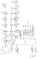
次に、上記の如く構成されたカメラ10の画像消去モードについて図1〜図4を用いて説明する。図4はカメラ10の画像消去モード時における消去動作を示すフローチャートである。カメラ10のCPU82は、はじめにモード判別を行い(ステップS210)、モード切換レバー42によって「再生モード」が選択されているか否かを判断する。「再生モード」が選択されていない場合、すなわち「撮影モード」が選択されている場合には、カメラ10を「撮影モード」で使用できるようにするための内部処理を行い(ステップS212)、撮影可能な状態にセットする。
【0038】
その一方、ステップS210で「再生モード」が選択されている場合には、メモリカード94(図3参照)から最終の画像データを読み出して画像再生処理を行い(ステップS214)、液晶モニタ38に再生画像を一コマ表示させる(ステップS216)。
【0039】
この一コマ再生時において、十字キー44(図2参照)の左キー44Lは逆方向コマ送り(コマ戻し)の指示入力キーとして機能し、右キー44Rは順方向コマ送りの指示入力キーとし機能する。撮影者は左キー44L又は右キー44Rを操作することにより再生対象の画像を選択することが可能である。CPU82では十字キー44からの指令を監視し、コマ送りの指示が入力されたか否かを判断する(ステップS218)。コマ送りの指示が入力された場合には、その指示に従って前コマ又は次コマの画像データをメモリカード94から読み出すとともに(ステップS219)、当該読み出した画像データの再生処理を実行して液晶モニタ38の表示画像を更新する(ステップS214〜S216)。
【0040】
CPU82は、ステップS218でコマ送りの指令が入力されていないと判断した時にはステップS220に進み、画像消去モードが選択されたか否かを判定する。ステップS220で「画像消去モード」に移行されていなければステップS221に進み、再生モードの終了操作が行われたか否かを判別する。ステップS221において再生モードの終了操作が行われていなければステップS216に戻り、継続して画像再生状態となる。なお、ステップS221で再生モードの終了操作が行われた場合には、当該再生モードを終了する。
【0041】
一方、ステップS220で画像消去モードに移行した場合(メニュー/OKボタン52が押された場合)、はじめにCPU82は記録画質の現在の圧縮率設定および撮影画素数設定から、新たに撮影する画像のデータサイズ(記録画像容量X)を見積る演算を行ない、これを記録画像容量Xとして取得する(ステップS222)。次いで、CPU82は記録媒体の残容量Rを取得する(ステップS224)。さらにCPU82は、撮影者によって選択された画像、すなわち液晶モニタ38に表示されている画像の容量Dを取得する(ステップS226)。
【0042】
ステップS228では、CPU82によって前記ステップS222,224,226で求めた記録画像容量X、記録媒体残容量R、表示画像容量Dをもとに、消去前の現撮影可能枚数Tおよび、消去後の撮影可能枚数Sが算出される。これらは、
【0043】
【数1】
現撮影可能枚数:T=R÷X
【0044】
【数2】
消去後撮影可能枚数:S=(R+ D)÷X
として夫々求められる。すなわち、記録媒体残容量Rを記録画像容量Xにて除して得られる現撮影可能枚数Tと(数1)、記録媒体残容量Rに表示画像容量D、つまり画像を消去した場合の容量増加分を加えた容量を、記録画像容量Xにて除して算出される消去後撮影可能枚数Sと(数2)、が夫々算出される。なお、この際の算出結果における小数点以下の端数は切り捨てされる。
【0045】
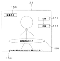
この後、現撮影可能枚数Tおよび消去後撮影可能枚数Sが画像情報として液晶モニタ38に表示される(ステップS230)。図5は、この消去画像および消去確認メッセージを示す液晶モニタ38の画面例である。同図に示すように、液晶モニタ38にはメモリカード94から読み出された画像(消去画像)に加えて、画面の中央には「画像消去OK?」という消去確認メッセージ150、画面の右側には現撮影可能枚数Tを示す現撮影可能枚数表示152および、消去後の撮影可能枚数Sを示す消去後撮影可能枚数表示154がキャラクタジェネレータ88(図3参照)によって再生画像に重畳されて表示されている。ここで、同図を説明すると、現撮影可能枚数表示152に「10枚」、消去後撮影可能枚数表示154には「13枚」と表示されることで、液晶モニタ38に表示されている画像を消去すれば撮影可能枚数が3枚増加する旨の表示がなされている。なお、同画面の左上の符号156は現在のモード(画像消去モード)を示すモード表示である。また、このときの液晶パネル38の表示構成として、同図に示すように「この表示画像はFINE MODEで撮影されています。」といった記録画質の情報158を加えても良い。
【0046】
この際に、撮影者は液晶モニタ38に表示される画像をコマ送り(順方向/逆方向送り)して消去画像を選択することもできる。図4に示すステップS232において、CPU82では十字キー44からの指令を監視し、コマ送りの指示が入力されたか否かを判断する。右キー44Rおよび左キー44Lの操作によるコマ送りの指示が入力された場合には、その指示に従って前コマ又は次コマの画像データをメモリカード94から読み出すとともに(ステップS234)、前記ステップ226まで戻り、当該読み出した画像データの再生処理および演算処理を実行し、液晶モニタ38の表示画像を更新して、新たな消去画像、消去確認メッセージ、現撮影可能枚数T、消去後撮影可能枚数Sを表示する(ステップS226〜S230)。
【0047】
前記ステップ232にてキー操作入力されていないと判断した場合には、ステップS236に進み、メニュー/OKボタン52の操作入力を受け付ける。このとき、メニュー/OKボタン52が操作されると、CPU82は液晶モニタ38に表示された画像の画像データ(選択された画像データ)をメモリカード94から消去する(ステップS238)。次いで、前記ステップS224に戻り、消去後の記録媒体残容量R′をあらためて取得した後、当該消去画像の前コマ又は次コマの画像データの演算処理を実行し、液晶モニタ38の表示画像を更新する(ステップS226〜S230)。
【0048】
前記ステップS236にてメニュー/OKボタン52が操作されていないと判断した場合にはステップS240に進み、画像消去モードの終了操作が行われたか否かを判別する。ステップS240において画像消去モードの終了操作が行われていなければ前記ステップS232に戻り、画像消去モードが継続され、消去すべき画像の選択をやり直すことができる。ステップS240でモードの終了操作が行われた場合には、画像消去モードを終了し、前記ステップS210まで戻る。
【0049】
なお、上述した一連の画像消去モードにおいて、撮影者によってBACKボタン54が操作されると画像消去モードがキャンセルされ、前記ステップS214に戻る。
【0050】
このように、上述した本実施の形態によれば、十字キー44で選択された画像データの容量を算出し、この容量を示す情報、すなわち現撮影可能枚数T、消去後撮影可能枚数Sを選択された画像とともに液晶モニタ38に表示させるので、撮影者は当該選択された画像を消去することなく、消去により増加する容量すなわち純増枚数を把握することができる。これにより撮影者は、所望の撮影可能枚数を得るために消去すべき画像の選択が容易に行える。また、消去前の段階で消去後の純増枚数を知ることができるので、この純増枚数を参考にしながら消去する画像を検討できる。ここで、消去後撮影可能枚数Sから現撮影可能枚数Tを差分した枚数、すなわち純増枚数を液晶モニタ38に表示させる構成としてもよい。
【0051】
なお、本実施の形態に示すように、容量を示す情報として現撮影可能枚数Tおよび消去後撮影可能枚数Sの表示が液晶モニタ38に表示される構成としたが、これに限らず、たとえばステータス表示部46に表示される構成としても構わない。また、さらに別の態様として、現撮影可能枚数Tや消去後撮影可能枚数Sに換えて記録画像容量X、記録媒体残容量R、表示画像容量Dを液晶モニタ38に表示する構成としても構わないが、撮影者による直感的な撮影可能枚数の把握を容易にするため、あくまで枚数表示とすることが好ましい。
【0052】
ここで、画像消去モード時における画像消去動作の態様は図5で説明した一コマ再生時に限定されず、例えばマルチ画面再生(サムネイル表示)中に容量を示す情報を表示させる態様も可能である。詳しく説明すると、まず再生モード時において表示ボタン50(図2参照)を操作して液晶モニタ38をマルチ画面再生とする。これによりメモリカード94から複数の画像データが読み出され、図6に示すように液晶モニタ38にサムネイル画像が表示される。次いでメニュー/OKボタン52を操作して画像消去モードに移行させると、液晶モニタ38のサムネイル画像には消去画像を選択するための画像選択フレーム140が表示される。この画像選択フレーム140は、十字キー44(図2参照)の上キー44U、下キー44D、左キー44Lおよび右キー44Rを操作して上下左右の4方向のサムネイルに移動でき、消去したい画像のサムネイル画像を選択できる。この画像選択フレーム140によるサムネイル画像の選択に伴い、CPU82では前記ステップ226〜230(図4参照)の演算が行なわれ、画像選択フレーム140にて選択された現撮影可能枚数Tを示す現撮影可能枚数表示160、消去後撮影可能枚数Sを示す消去後撮影可能枚数162などの情報が表示される。このときメニュー/OKボタン52が操作されると、画像選択フレーム140にて選択されたサムネイル画像の画像データがメモリカード94から消去される。
【0053】
このような態様においても、撮影者は当該選択された画像を消去すること無く純増枚数を把握することができる。なお、この後の動作については前述した一コマ画像再生における手順と同様であるので、その説明を省略する。
【0054】
ここで、上述した画像消去モードでの一コマ再生/マルチ画面再生において、選択画像の表示順番の構成を一般的な撮影日時順の表示構成とする日付順表示モードに加えて、各画像の容量(画像データサイズ)順の表示構成、すなわち容量順表示モードとすれば、大きいサイズの画像から順次消去対象を選択できる。これにより撮影者は、消去すべき画像を容易に選択でき、少ない消去回数で効率よく所望の撮影可能枚数を得ることができる。
【0055】
なお、純増枚数の目安について補足すると、例えば高画質(低圧縮率)の「FINE」MODEで撮影された容量800kB程度の画像を消去する場合、撮影可能枚数は、高圧縮率の「BASIC」(容量200kB程度)の画像であれば3〜4枚程増加する。
【0056】
前述した実施の形態に示したデジタルカメラの構成は、前記実施の形態に限定されるものではない。例えば、前記ステップS222における記録画像容量Xは、記録画質の現在の圧縮率設定および撮影画素数設定から算出する構成としたが、これに限らず、選択画像の記録画質と同じ設定が維持されてもよいし、一律に予め定めた固定の圧縮率(例えば、「NORMAL」)としてもよい。予め圧縮率設定や撮影画素数設定に基づいて記録画像容量Xが設定され、ROM108やEEPROM110などに記憶された構成としてもよい。
【0057】
また、上記実施の形態においては静止画を消去する場合を例として用いて説明したが、静止画のみならず動画の消去にも本発明を適用できる。さらに、本実施の形態ではカメラ本体に着脱可能なメモリカードから画像が消去される構成としているが、カメラ10に記録媒体(内蔵メモリ)が内蔵されたデジタルカメラの場合には、この内蔵メモリから記憶された画像データを消去する構成としてもよいことは言うまでもない。
【0058】
なお、本発明の適用範囲はデジタルカメラに限定されず、例えばビデオカメラ、撮影機能付き携帯電話機、パソコン、PDAなど、画像データを取り扱う様々な機器に広く適用できる。
【0059】
【発明の効果】
以上、説明したように本発明に係るデジタルカメラによれば、画像選択操作手段で選択された画像データの容量を算出し、この容量を示す情報を選択された画像とともに画像表示手段に表示させるので、撮影者は当該選択された画像を消去することで増加する容量を把握することができる。
【図面の簡単な説明】
【図1】本発明の実施の形態に係るデジタルカメラの一例を示す斜視図
【図2】本発明の実施の形態に係るデジタルカメラの一例を示す背面図
【図3】本発明の実施の形態に係るデジタルカメラの内部構成を示すブロック図
【図4】本発明の実施の形態に係るデジタルカメラの動作を示すフローチャート
【図5】本発明の実施の形態に係るデジタルカメラの画像消去モード時に液晶モニタ上に表示される画像の一例を示す図
【図6】本発明の実施の形態に係るデジタルカメラの画像消去モード時に、液晶モニタ上に表示される画像の別の一例を示す図
【符号の説明】
10…カメラ、38…液晶モニタ(LCD)、44…十字キー、52…メニュー/OKボタン、78…RAM、82…CPU、94…メモリカード(記録媒体)、152,160…現撮影可能枚数表示、154,160…消去後撮影可能枚数表示[0001]
BACKGROUND OF THE INVENTION
The present invention relates to a digital camera, and more particularly to a digital camera provided with an image erasing unit and capable of erasing a captured image from a recording medium.
[0002]
[Prior art]
With conventional digital cameras, the number of storable images on the recording medium (recordable time for movie shooting, etc.) is notified to the photographer at the time of shooting. The image is displayed on a provided liquid crystal monitor (LCD) for image reproduction display, a status display unit, or the like. As a result, the photographer can easily know, for example, when the recording medium has a small free space and it is difficult to shoot. In this case, as is well known, a photographed image (image data) is read from the recording medium. If the free space of the recording medium is increased by erasing, new shooting can be performed (see, for example, Patent Document 1).
[0003]
[Patent Document 1]
Japanese Patent Laid-Open No. 3-267881
[0004]
[Problems to be solved by the invention]
However, such a digital camera has a problem in that it cannot be known how much the free space can be increased by erasing image data unless the image data is actually erased. That is, for example, when the normal mode and fine mode are mixed in the image quality setting of the image data to be erased, it is impossible to know whether the desired number of shootable images can be secured without actually erasing. . Further, if all the image data to be erased are images taken in the normal mode, it is not possible to grasp how many pieces of image data need to be erased in order to photograph one fine mode image.
[0005]
As described above, the free space that is increased by erasing the image data can be known only after the image data is erased. Therefore, in order to secure a desired free space, trial is performed while erasing some image data. There was a drawback that it was necessary to make mistakes and the work was complicated.
[0006]
The present invention has been made in view of such circumstances, and an object of the present invention is to provide a digital camera capable of presenting a photographer with the number of shootable images after erasing image data that has already been taken.
[0007]
[Means for solving the problems]
In order to achieve the above object, the present invention provides an image quality setting means capable of setting at least one of the number of photographed pixels and a compression rate of an image recorded on a recording medium, and a current image quality set by the image quality setting means. Based on the first capacity acquisition means for acquiring the capacity of the captured image based on the setting, the remaining capacity of the recording medium, and the capacity acquired by the first capacity acquisition means, the first number of shootable images is calculated. A means for displaying the first number of shootable images on a display means; an image selection means for selecting an image recorded on the recording medium; and an image display means for displaying an image selected by the image selection means; In the erase mode, if there is a first erase instruction input for erasing the image during image display by the image display means, an erase confirmation state is entered, and if a second erase instruction input is entered in the erase confirmation state, the Image In a digital camera having an image erasing unit for erasing from a recording medium, a second capacity acquisition unit that acquires a capacity obtained by adding a capacity of an image selected by the image selection unit to a remaining capacity of the recording medium; Calculating means for calculating a second shootable number based on the respective capacities acquired by the first and second capacity acquiring means; and the calculating means together with the first shootable number in the erasure confirmation state in the erasing mode. Display control means for causing the display means to display the second number of shootable images calculated by the above or the difference between the first number of shootable images and the second number of shootable images.
[0008]
According to the present invention, in the erasure mode, the number of shootable images before erasure and the number of shootable images after erasure of the selected image are respectively displayed, or the difference between the number of shootable images before erasure and the number of shootable images after erasure is displayed. Is displayed, the photographer can grasp the number of shootable images (net increase) that is increased by deleting the image.
[0009]
According to the second aspect of the present invention, the image selection means selects a desired image by sequentially feeding the images to be displayed on the image display means. Since there is a first frame advance mode for frame advance and a second frame advance mode for sequentially moving images in the order of capacity, the photographer can easily delete images to be deleted in order to obtain a desired number of shootable images. This makes it possible to efficiently increase the number of images that can be taken with a small number of erasures.
[0010]
DETAILED DESCRIPTION OF THE INVENTION
Hereinafter, preferred embodiments of a digital camera according to the present invention will be described in detail with reference to the accompanying drawings.
[0011]
FIG. 1 is a perspective view showing an example of a digital camera according to an embodiment of the present invention. On the front surface of the main body 11 of the camera 10, a retractable photographing lens 12, a finder window 14, a strobe light control sensor 16, a self-timer lamp 18, a microphone unit 20, and the like are provided. A CCD image sensor (not shown in FIG. 1; described as reference numeral 68 in FIG. 3; hereinafter referred to as a CCD) is disposed behind the photographic lens 12, and an image signal read from the CCD 68 is a predetermined signal. It is converted into digital image data through the signal processing.
[0012]
On the side surface of the camera 10, a speaker 21, a digital (USB) terminal 22, an audio / video output terminal (VIDEO OUT) 23, a power input terminal (for example, a terminal for DC IN 3V) 24, and the like are provided. Reference numeral 25 in FIG. 1 denotes a memory card slot cover (card cover).
[0013]
On the top surface of the camera 10, a shutter button 30, a mode dial 32, a pop-up strobe light emitting device 34, and the like are provided. Reference numeral 35 provided on the side surface of the main body 11 is a strobe pop-up button.
[0014]
The mode dial 32 is an operation means for selecting operation modes such as continuous shooting, manual shooting, auto shooting, scene position, moving image recording, and voice recorder.
[0015]
FIG. 2 is a rear view of the camera 10. As shown in the figure, a finder 36, a liquid crystal monitor (LCD) 38, a power switch 40, a mode selection lever 42, a cross key 44, a status display unit 46, a display button 50, and a menu / OK button 52 are provided on the back of the camera 10. , A BACK button 54 and the like are provided.
[0016]
The liquid crystal monitor 38 is composed of a color liquid crystal display, and displays an image captured via the CCD 68 and a reproduced image read from a memory card (denoted by reference numeral 94 in FIG. 3) (single frame reproduction / multi-screen reproduction, etc.). At the same time, various information such as mode information, battery level warning, shooting date and time, and playback frame number are also displayed.
[0017]
The mode selection lever 42 is an operation means for selectively switching between the photographing mode and the reproduction mode. The mode selection lever 42 is rotatably supported on the outer periphery of the power switch 40, and is configured by a lever switch that can be stopped at two positions, a shooting mode position (upper stop position) and a playback mode position (lower stop position). Yes.
[0018]
The cross key 44 is composed of four push-type switches including an upper key 44U, a lower key 44D, a left key 44L, and a right key 44R, and is an operation unit for inputting instructions in four directions, up, down, left, and right. The cross key 44 functions as a button for selecting an item from the menu screen or instructing selection of various setting items from each menu. Further, the upper key 44U and the lower key 44D of the cross key 44 function as a zoom switch in the shooting mode or a playback zoom switch in the playback mode, and the right key 44R and the left key 44L move forward (forward direction) in the playback mode. Functions as a (Reverse feed) button.
[0019]
A circular window portion 56 is formed inside these four keys, and a status display portion 46 is provided in the window portion 56. The status display unit 46 is composed of, for example, a dot matrix liquid crystal, and displays information indicating functions and mode states of the upper, lower, left, and right keys 44U, 44D, 44L, and 44R.
[0020]
The display button 50 is used to turn on / off the display on the liquid crystal monitor 38 and to display / hide an OSD (on-screen display) display such as a playback method (single frame playback / multi-screen playback) and a frame number during playback. It is an operation means for switching.
[0021]
The menu / OK button 52 is an operation having both a function as a menu button for instructing to display a menu on the screen of the liquid crystal monitor 38 and a function as an OK button for instructing confirmation and execution of selection contents. Key. The photographer operates the upper key 4U or the lower key 44D of the cross key 44, selects an item to be changed from the menu, changes the setting contents with the left key 44L or the right key 44R, and confirms with the menu / OK button 52. To do. The menu includes various setting items such as recording quality (quality), number of photographing pixels, image erasing (image erasing mode), date setting, and selection of ON / OFF of the liquid crystal monitor 38 at startup. Of these, the recording image quality setting item has three types of image quality (compression ratio): “FINE” for high image quality (low compression rate), “NORMAL” for standard image quality, and “BASIC” for high compression rate. Can be set. In the setting item of the number of photographic pixels (pixels), any of the recording pixel numbers of 2832 × 2128 (6M), 2048 × 1536 (3M), 1280 × 960 (1M), and 640 × 480 (VGA) can be selected. . In the present embodiment, it is possible to change both the recording image quality and the number of shooting pixels. However, a digital camera in which only one of the recording image quality and the number of shooting pixels can be set may be used.
[0022]
The BACK button 54 is used when canceling (cancelling) an item selected from the menu or returning to the previous operation state (undo). In FIG. 2, reference numeral 61 denotes a grip portion, and reference numeral 62 denotes a battery cover (battery cover).
[0023]
FIG. 3 is a block diagram of the camera 10. The photographing lens 12 is a zoom lens, but a single focus lens may be used. The light that has passed through the photographing lens 12 is incident on the CCD 68 after the amount of light is adjusted by the diaphragm 66. A large number of photosensors (light receiving elements) are two-dimensionally arranged on the light receiving surface of the CCD 68, and primary color filters of red (R), green (G), and blue (B) are provided for each photosensor. They are arranged in a predetermined arrangement structure (Bayer, G stripe, etc.). The CCD 68 has an electronic shutter function for controlling the charge accumulation time (shutter speed) of each photosensor.
[0024]
The subject image formed on the light receiving surface of the CCD 68 via the photographing lens 12 is converted into signal charges of an amount corresponding to the amount of incident light by each photosensor. The signal charge accumulated in each photosensor is sequentially read out as a voltage signal (image signal) corresponding to the signal charge based on a pulse supplied from the CCD driver 70. The image signal output from the CCD 68 is sent to the analog processing unit 72. The analog processing unit 72 includes a signal processing circuit such as a sampling hold circuit, a color separation circuit, and a gain adjustment circuit. In this analog processing unit 72, the correlated double sampling (CDS) process and the R, G, B color signals are colored. Separation processing is performed, and signal level adjustment (pre-white balance processing) of each color signal is performed.
[0025]
The signal output from the analog processing unit 72 is converted to a digital signal by the A / D converter 74 and then stored in the RAM 78 constituting the internal memory via the internal buffer 76 and the bus 84. A timing signal is given from the timing generator 77 to the CCD driver 70, the analog processing unit 72, and the A / D converter 74, and each circuit is synchronized by this timing signal.
[0026]
The image data stored in the RAM 78 is sent to the signal processing unit 80. The signal processing unit 80 includes an image signal processing circuit such as a synchronization circuit, a luminance / color difference signal generation circuit, a gamma correction circuit, a sharpness correction circuit, a contrast correction circuit, a white balance correction circuit, an electronic zoom processing circuit, a trimming processing circuit, and an audio signal. The signal processing means is constituted by a digital signal processor (DSP) including a processing circuit, and processes image signals and audio signals while utilizing the RAM 78 in accordance with commands from the CPU 82. The image data input to the signal processing unit 80 is converted into a luminance signal (Y signal) and a color difference signal (Cr, Cb signal) and subjected to predetermined processing such as gamma correction and then stored in the RAM 78. The
[0027]
When the captured image is displayed and output, the luminance / color difference signal (abbreviated as YC signal) stored in the RAM 78 is sent to the VRAM 86 via the bus 84. The data stored in the VRAM 86 is sent to the encoder 87, where it is converted into a predetermined display signal (for example, an NTSC color composite video signal) together with character and symbol data supplied from the character generator 88. . The output of the encoder 87 is converted to an analog signal via the D / A converter 89 and then output to the liquid crystal monitor 38. In this way, the image content of the image data is displayed on the screen of the liquid crystal monitor 38.
[0028]
The image data in the RAM 78 is periodically rewritten by the image signal output from the CCD 68, and the video signal generated from the image data is supplied to the liquid crystal monitor 38, so that the image input via the CCD 68 is real-time. It is displayed on the liquid crystal monitor 38. The photographer can confirm the image angle of view by using the image (through image) displayed on the liquid crystal monitor 38 or the viewfinder 36.
[0029]
When a shooting mode is selected by the mode selection lever 42 (see FIG. 2) and the shutter button 30 is pressed, a shooting start instruction (release ON) signal is issued. In response to the reception of this instruction signal, the CPU 82 starts taking in image data for recording. Further, the CPU 82 sends a command to the compression / decompression circuit 90, whereby the compression / decompression circuit 90 compresses the image data on the RAM 78 in accordance with JPEG or another predetermined format.
[0030]
The compressed image data is recorded on the memory card 94 via the card interface 92. In the camera 10 of this example, for example, smart media (Solid-State FloppyDiskCard) is applied as means for storing image data and the like. Note that the form of the recording medium is not limited to this, and may be, for example, a PC card, a compact flash, an XD picture card, or the like, and various media that can be read and written according to an electronic, magnetic, optical, or a combination thereof. Can be used.
[0031]
When the playback mode is selected by the mode selection lever 42, the last image data recorded on the memory card 94, that is, the last recorded image data is read out. The image data read from the memory card 94 is decompressed by the compression / decompression circuit 90 and output to the liquid crystal monitor 38 via the VRAM 86, encoder 87, and D / A converter 89. Note that data generated by the character generator 88 (such as the current shootable number display 152 and the erasureable number display 154 shown in FIG. 5) is superimposed on the image signal and displayed on the liquid crystal monitor 38.
[0032]
During single-frame playback in the playback mode, the left / right keys 44L and 44R of the cross key 44 can be operated to forward (forward) frames in the forward direction or backward direction. Are read from the memory card 94 and an image is reproduced in the same manner as described above.
[0033]
The CPU 82 functions as a control unit that controls the camera system according to a predetermined program, and also sets the current compression rate setting (“FINE”, “NORMAL”, “BASIC”) and the current number of pixels to be photographed. From (6M, 3M, 1M, VGA), a calculation is performed to estimate the data size (recorded image capacity X) of a newly captured image. In other words, based on the compression rate setting and shooting pixel setting specified in advance by the photographer in the shooting mode, a calculation for predicting the data size of the image data at the time of new shooting is performed, and this is obtained as the recorded image capacity X. To do. In addition, the CPU 82 is a calculation means for performing various calculations such as a calculation of a remaining capacity (free capacity) R of a recording medium, which will be described later, and a calculation of a display image capacity D of a reproduced image displayed on the liquid crystal monitor 38. In addition to functioning, the power switch 40, the shutter button 30, and other control operations of the corresponding circuit based on the input signal received from the operation unit 105, lens drive control, photographing operation control, strobe light emission control, image signal processing control, image Data recording / reproduction control, display control on the liquid crystal monitor 38, and the like are also performed.
[0034]
On the other hand, the RAM 78 is used as a program development area and a calculation work area for the CPU 82, and as a temporary storage area for a recording medium remaining capacity R, a display image capacity D, and a recording image capacity X in addition to image data and sound data. Is also used.
[0035]
The ROM 108 connected to the CPU 82 via the bus 84 stores programs executed by the CPU 82 and various data necessary for control. Further, an EEPROM (nonvolatile memory) 110 connected to the CPU 82 stores data necessary for control, various setting information, and the like in advance.
[0036]
As the power source of the camera 10, an external power source such as an AC power adapter (not shown) connected to the battery 126 or the power input terminal 24 (see FIG. 1) can be used. The power supplied from the battery 126 or the like is converted into a required voltage by a power supply circuit 128 including a DC / DC converter, and then supplied to each circuit block.
[0037]
Next, the image erasing mode of the camera 10 configured as described above will be described with reference to FIGS. FIG. 4 is a flowchart showing the erasing operation when the camera 10 is in the image erasing mode. The CPU 82 of the camera 10 first determines the mode (step S210), and determines whether or not the “reproduction mode” is selected by the mode switching lever 42. When the “reproduction mode” is not selected, that is, when the “shooting mode” is selected, internal processing for enabling the camera 10 to be used in the “shooting mode” is performed (step S212). Set it to a possible state.
[0038]
On the other hand, if “reproduction mode” is selected in step S210, the final image data is read from the memory card 94 (see FIG. 3), image reproduction processing is performed (step S214), and reproduction is performed on the liquid crystal monitor 38. One frame of image is displayed (step S216).
[0039]
During this single frame playback, the left key 44L of the cross key 44 (see FIG. 2) functions as a reverse frame advance (frame reverse) instruction input key, and the right key 44R functions as a forward frame advance instruction input key. To do. The photographer can select an image to be reproduced by operating the left key 44L or the right key 44R. The CPU 82 monitors a command from the cross key 44 and determines whether or not a frame advance instruction has been input (step S218). When a frame advance instruction is input, the image data of the previous frame or the next frame is read from the memory card 94 in accordance with the instruction (step S219), and the read-out processing of the read image data is executed to perform the liquid crystal monitor 38. The display image is updated (steps S214 to S216).
[0040]
When the CPU 82 determines in step S218 that the frame advance command has not been input, the CPU 82 proceeds to step S220 and determines whether or not the image erasing mode has been selected. If it is not shifted to the “image erasing mode” in step S220, the process proceeds to step S221, and it is determined whether or not a reproduction mode end operation has been performed. If the end operation of the reproduction mode is not performed in step S221, the process returns to step S216, and the image reproduction state is continued. Note that if the playback mode end operation is performed in step S221, the playback mode ends.
[0041]
On the other hand, when the mode is shifted to the image erasing mode in step S220 (when the menu / OK button 52 is pressed), first, the CPU 82 sets the image data to be newly taken from the current compression rate setting and shooting pixel number setting of the recording image quality. A calculation for estimating the size (recorded image capacity X) is performed, and this is acquired as the recorded image capacity X (step S222). Next, the CPU 82 acquires the remaining capacity R of the recording medium (step S224). Further, the CPU 82 acquires the capacity D of the image selected by the photographer, that is, the image displayed on the liquid crystal monitor 38 (step S226).
[0042]
In step S228, based on the recorded image capacity X, the remaining recording medium capacity R, and the display image capacity D obtained by the CPU 82 in steps S222, 224, and 226, the current number of shootable images T before erasure and the shoot after erasure. The possible number S is calculated. They are,
[0043]
[Expression 1]
Current number of possible shots: T = R ÷ X
[0044]
[Expression 2]
Number of storable pictures after erasure: S = (R + D) ÷ X
As required. That is, the current shootable number T obtained by dividing the recording medium remaining capacity R by the recording image capacity X (Equation 1), and the display image capacity D, that is, the capacity increase when the image is erased, to the recording medium remaining capacity R The post-erase shootable number S and (Equation 2) calculated by dividing the added capacity by the recorded image capacity X are respectively calculated. Note that the fractional part of the calculation result at this time is rounded down.
[0045]
Thereafter, the current number of shootable images T and the number of shootable images after erasure S are displayed as image information on the liquid crystal monitor 38 (step S230). FIG. 5 is a screen example of the liquid crystal monitor 38 showing the erased image and the erase confirmation message. As shown in the figure, in addition to the image (erase image) read from the memory card 94 on the liquid crystal monitor 38, an erase confirmation message 150 "Image erase OK?" Is displayed by the character generator 88 (see FIG. 3) superimposed on the replayed image, the current shootable number display 152 showing the current shootable number T and the post-erase shootable number display 154 showing the shootable number S after erasure. ing. Here, to explain this figure, “10 sheets” is displayed on the current shootable image number display 152 and “13 images” is displayed on the shootable image number display 154 after erasure, so that the image displayed on the liquid crystal monitor 38 is displayed. A message is displayed indicating that the number of images that can be shot will increase by 3 if the is deleted. Note that reference numeral 156 in the upper left of the screen is a mode display indicating the current mode (image erasing mode). Further, as the display configuration of the liquid crystal panel 38 at this time, as shown in the figure, information 158 of the recording image quality such as “This display image is taken in the FINE MODE” may be added.
[0046]
At this time, the photographer can also select an erased image by frame-by-frame (forward / reverse feeding) the image displayed on the liquid crystal monitor 38. In step S232 shown in FIG. 4, the CPU 82 monitors a command from the cross key 44 and determines whether or not a frame advance instruction is input. When a frame advance instruction is input by operating the right key 44R and the left key 44L, the image data of the previous frame or the next frame is read from the memory card 94 according to the instructions (step S234), and the process returns to the step 226. Then, the reproduction processing and the calculation processing of the read image data are executed, the display image on the liquid crystal monitor 38 is updated, and a new erased image, an erase confirmation message, the current number of shootable images T, and the number of shootable images S after erasure are displayed. (Steps S226 to S230).
[0047]
If it is determined in step 232 that no key operation has been input, the process proceeds to step S236 to accept an operation input of the menu / OK button 52. At this time, when the menu / OK button 52 is operated, the CPU 82 erases the image data (selected image data) of the image displayed on the liquid crystal monitor 38 from the memory card 94 (step S238). Next, the process returns to step S224, and after the erasure of the remaining recording medium capacity R 'is newly obtained, the calculation processing of the image data of the previous frame or the next frame of the erased image is executed, and the display image of the liquid crystal monitor 38 is updated. (Steps S226 to S230).
[0048]
If it is determined in step S236 that the menu / OK button 52 has not been operated, the process proceeds to step S240, where it is determined whether or not an image erasing mode end operation has been performed. If the operation for ending the image erasing mode is not performed in step S240, the process returns to step S232, the image erasing mode is continued, and the selection of the image to be erased can be performed again. When the mode end operation is performed in step S240, the image erasing mode is ended, and the process returns to step S210.
[0049]
In the above-described series of image erasing modes, when the photographer operates the BACK button 54, the image erasing mode is canceled and the process returns to step S214.
[0050]
As described above, according to the present embodiment described above, the capacity of the image data selected by the cross key 44 is calculated, and information indicating this capacity, that is, the current number of shootable images T and the number of shootable images after erasure S are selected. Since the image is displayed on the liquid crystal monitor 38 together with the selected image, the photographer can grasp the capacity increased by the deletion, that is, the net increase in number without deleting the selected image. As a result, the photographer can easily select an image to be erased in order to obtain a desired number of shootable images. In addition, since it is possible to know the net increase in number after erasure at the stage before erasure, the image to be erased can be examined with reference to the net increase in number. Here, the liquid crystal monitor 38 may be configured to display a number obtained by subtracting the current number of shootable images T from the number of shootable images S after erasure, that is, a pure increase number.
[0051]
As shown in the present embodiment, the display of the current shootable number T and the erasable shootable number S is displayed on the liquid crystal monitor 38 as information indicating the capacity. However, the present invention is not limited to this. A configuration displayed on the display unit 46 may be used. As another aspect, the recording image capacity X, the remaining recording medium capacity R, and the display image capacity D may be displayed on the liquid crystal monitor 38 in place of the current shootable number T and the erasable number S. However, in order to make it easier for the photographer to intuitively grasp the number of images that can be shot, it is preferable to display the number of images.
[0052]
Here, the mode of the image erasing operation in the image erasing mode is not limited to the one-frame playback described with reference to FIG. 5, and for example, a mode in which information indicating the capacity is displayed during multi-screen playback (thumbnail display) is also possible. More specifically, first, the display button 50 (see FIG. 2) is operated in the playback mode, and the liquid crystal monitor 38 is set to multi-screen playback. As a result, a plurality of image data is read from the memory card 94, and a thumbnail image is displayed on the liquid crystal monitor 38 as shown in FIG. Next, when the menu / OK button 52 is operated to shift to the image erasing mode, an image selection frame 140 for selecting an erasure image is displayed on the thumbnail image of the liquid crystal monitor 38. The image selection frame 140 can be moved to thumbnails in four directions, up, down, left, and right by operating the up key 44U, down key 44D, left key 44L, and right key 44R of the cross key 44 (see FIG. 2). A thumbnail image can be selected. In accordance with the selection of the thumbnail image by the image selection frame 140, the CPU 82 performs the operations of the above steps 226 to 230 (see FIG. 4), and can perform the current photographing that indicates the current number of shootable images T selected in the image selection frame 140. Information such as the number display 160, the number of shootable images 162 after erasing indicating the number of shootable images after erasure S is displayed. At this time, when the menu / OK button 52 is operated, the image data of the thumbnail image selected in the image selection frame 140 is erased from the memory card 94.
[0053]
Even in such an aspect, the photographer can grasp the net increase in number without deleting the selected image. Since the subsequent operation is the same as that in the above-described single frame image reproduction, the description thereof will be omitted.
[0054]
Here, in the single-frame playback / multi-screen playback in the image erasure mode described above, in addition to the date order display mode in which the configuration of the display order of the selected images is the display configuration of the general shooting date order, the capacity of each image If the display configuration is in the order of (image data size), that is, the capacity order display mode, it is possible to sequentially select objects to be erased from images of a large size. Thus, the photographer can easily select an image to be erased, and can efficiently obtain a desired number of images that can be photographed with a small number of times of erasure.
[0055]
To supplement the guideline for the net increase in number, for example, when erasing an image with a capacity of about 800 kB shot in “FINE” MODE with high image quality (low compression rate), the number of shots that can be taken is “BASIC” (with high compression rate). If the image has a capacity of about 200 kB, the number increases by about 3 to 4 sheets.
[0056]
The configuration of the digital camera described in the above embodiment is not limited to the above embodiment. For example, the recording image capacity X in step S222 is calculated from the current compression rate setting and recording pixel number setting of the recording image quality, but is not limited thereto, and the same setting as the recording image quality of the selected image is maintained. Alternatively, a fixed compression rate (for example, “NORMAL”) that is uniformly determined in advance may be used. The recording image capacity X may be set in advance based on the compression rate setting or the number of captured pixels, and may be stored in the ROM 108, the EEPROM 110, or the like.
[0057]
In the above embodiment, the case of erasing a still image has been described as an example. However, the present invention can be applied to erasing not only a still image but also a moving image. Further, in this embodiment, the image is erased from a memory card that can be attached to and detached from the camera body. However, in the case of a digital camera in which a recording medium (built-in memory) is built in the camera 10, the built-in memory is used. Needless to say, the stored image data may be erased.
[0058]
The application range of the present invention is not limited to a digital camera, and can be widely applied to various devices that handle image data, such as a video camera, a mobile phone with a photographing function, a personal computer, and a PDA.
[0059]
【The invention's effect】
As described above, according to the digital camera of the present invention, the capacity of the image data selected by the image selection operation means is calculated, and information indicating this capacity is displayed on the image display means together with the selected image. The photographer can grasp the capacity that is increased by deleting the selected image.
[Brief description of the drawings]
FIG. 1 is a perspective view illustrating an example of a digital camera according to an embodiment of the present invention.
FIG. 2 is a rear view showing an example of a digital camera according to an embodiment of the present invention.
FIG. 3 is a block diagram showing an internal configuration of the digital camera according to the embodiment of the present invention.
FIG. 4 is a flowchart showing the operation of the digital camera according to the embodiment of the present invention.
FIG. 5 is a diagram showing an example of an image displayed on the liquid crystal monitor when the digital camera according to the embodiment of the present invention is in an image erasing mode.
FIG. 6 is a diagram showing another example of an image displayed on the liquid crystal monitor when the digital camera according to the embodiment of the present invention is in an image erasing mode.
[Explanation of symbols]
DESCRIPTION OF SYMBOLS 10 ... Camera, 38 ... Liquid crystal monitor (LCD), 44 ... Cross key, 52 ... Menu / OK button, 78 ... RAM, 82 ... CPU, 94 ... Memory card (recording medium), 152, 160 ... Display of the number of possible shots , 154, 160 ... Number of shootable images after erasure