【0001】
【発明の属する技術分野】
本発明は、太陽電池アレイの施工方法により、配線部材を強固に固定することを可能にし、配線固定用架台及び傾斜作成部材を大幅に削減することが可能な太陽電池アレイに関する。
【0002】
【従来の技術】
近年、エネルギー資源の保護や環境問題に対する意識の高まりが、世界的に広がりを見せている。中でも、石油等の枯渇化やCO2排出に伴う地球の温暖化現象に対する危惧感は深刻である。そこで、太陽エネルギーを直接電力に変換でき、しかもクリーンなエネルギーである太陽電池エネルギーには、大きな期待が寄せられている。
【0003】
現在の太陽電池モジュールの市場は、住宅やビルなどの建築構造物への設置用や、携帯用(レジャー用)など様々な分野にわたっている。しかし、依然高価格であり、そのことが普及の最大の壁となっている。その対策の一つとして異分野の製品と太陽電池モジュールとを一体形成し、トータルコストを低減する方法が挙げられる。
【0004】
建築構造物に設置するタイプの代表的な例は、屋根への設置であるが、これには屋根上置き型、屋根材一体型などの太陽電池モジュールが脚光を浴びている。この理由としては、別部材として屋根材が必要ないため屋根を形成する総材料コストを低減することができ、また、設置する場合にも通常の屋根材設置と同様に設置することができるため施工コストをも低減することができ、トータルコストとして低コストで太陽電池モジュールを屋根に設置することができるからである。また外観上も周囲の屋根と調和して美しい屋根となる。
【0005】
この例に代表されるように近年の太陽電池モジュールは、様々な異分野の製品と太陽電池モジュールとを一体化することにより、その付加価値を高めている。即ち、両者の総材料コストや総製造コストについて共有化できる部分が存在し、その部分を共有化することで、その共有化されたコスト分がトータルコストとして観た場合に、大幅に低減することができる。
【0006】
一方、将来的に大きな市場になるであろうと注目されているものに、発電所としての市場がある。従来のエネルギーに代わる新エネルギー源として太陽光発電を用いようという動きがある。
【0007】
年々、増加し続ける消費電力を賄うために、毎年新たな発電所が建設されている。特に、日中の人が活動する時間や夏場の昼間に使用する冷房のためのエネルギーなどによる消費が非常に大きい。これらのエネルギーはピークエネルギーと呼ばれている。従来、増設される発電所は、火力発電、水力発電、及び原子力発電等であった。しかしながら最近では、地球温暖化対策、環境保護対策等を考慮した新エネルギーとして太陽光発電、風力発電、及び地熱発電などが注目されている。夏場や昼間のピークエネルギー時間帯とは、太陽光が照射する時間帯であるため、ピークエネルギーの時間帯に多くのエネルギーを発電する特性を持つ太陽光発電の注目度は高い。
【0008】
発電所の電力源として太陽電池モジュールを使用するには、現在の太陽電池の発電コストは非常に高い。したがって従来は、異分野の製品と太陽電池モジュールとを一体化することにより共有化できるコストを生み出し、それによりトータルコストの低減を行ってきた。
【0009】
しかし、発電所の電力源として太陽電池モジュールを考えた場合、必要なのは電力のみであり、その他の機能は必要ではない。即ち、火力発電など従来の電力源と併用して使用するには、高付加価値な太陽電池モジュールよりも太陽光発電での発電コストと従来の電力源での発電コストが同じであることが非常に重要な要素となっている。勿論、環境などを考慮した場合には、太陽光発電などクリーンなエネルギーを使用することが理想ではあるが、コストがあまりにも高い場合には、新エネルギー源が従来のエネルギー源に置き換わることは不可能である。この点において、現在の太陽電池モジュールの発電コストでは、発電所の電力源として使用することは難しい。
【0010】
ここで、上述した発電コストとは、以下のようなものである。
発電コスト=(年間装置費+年間修繕・保守費+年間燃料費)/年間発電量で表される。年間装置費とは、建設費の総額(初期投資額)を発電システムの耐用年数で割ったものである。ただし、この場合金利も考慮しなければならない。年間修繕・保守費とは、発電システムをメンテナンスするための年間費用の総額である。燃料費とは、発電システムの装置を稼動させるのに必要な燃料に費やす年間費用の総額である。
【0011】
太陽電池モジュールを使用する太陽光発電システムでは、無尽蔵な太陽エネルギーを使用するため年間燃料費は必要ない。修繕・保守費も、それほど多額ではない。太陽光発電システムで一番発電コストを高くする要因は、年間装置費である。即ち、太陽電池モジュールのワットコストが高いのである。
【0012】
このような状況において、太陽光発電を普及させ、発電所の電力源として使用するためには、太陽光発電のコストを大幅に低減することが必要不可欠である。即ち、太陽電池モジュールのワットコスト及びその設置コストを低減し、従来の発電システムの発電コストと競争力のある発電コストにまで低減することが必要不可欠である。
【0013】
さらに、上述した太陽電池モジュールのコストについて述べる。従来の発電コストは、太陽電池あるいは電気の専門家ではない一般消費者が使用し、それらの人々の手に触れることを前提に設計されている。ところがこのような方法では、安全性を高めるために多くの材料を必要するため原材料コストが高く、製造工程においては加熱圧着の工程が必要であるため生産性も落ち、その製造工数(man−hour)もかかるため生産コストが高くなる。即ち、トータルの発電コストが高くなる。このように従来の方法で太陽電池モジュールを生産している限り、太陽電池モジュールのワットコストを低減することには限界がある。
【0014】
発電所で使用する太陽電池モジュールの場合、管理環境下で利用される。ここで管理環境とは、電気あるいは太陽電池モジュールの専門家が管理する状況であって、取り扱い者以外の一般の人々が立ち入る虞れがない場所を意味する。この管理環境では、太陽電池モジュール外囲体の周りに柵や塀を設けたり、出入り口に施錠を設けたりといった対策を採る。また、取り扱い者により定期的なメンテナンスも可能な状況に置かれる。
【0015】
従来、太陽電池を屋根上などに設置している太陽光発電システムのメンテナンスを行う場合、屋根材上もしくは太陽電池モジュール上を踏みつけることが可能であったため問題なく作業を行うことができた。しかし、地上設置型の大規模な発電所向け太陽光発電システム等は、構成材料を極力削減した特定の太陽電池モジュールであるため架台上を踏みつけたり歩いたりすることが困難であり、太陽電池モジュールを破壊する可能性が生じる。そのため、通常は架台間に通路を設ける。このような場合、架台間を跨ぐ配線材は、風などの外力により配線切れや大地への配線の地絡を防止するために、配線部材を固定する配線固定用架台が必要になり、その分、設置コストが向上し作業効率が低下していた。このような架台を用いた太陽光発電装置は数多く知られている。
【0016】
例えば、特許文献1には、表裏面からの光により発電可能な太陽電池素子を複数個電気的に接続した太陽電池装置または太陽電池送置間に太陽電池装置の裏面側へ光を導くための光開口部が設けられている太陽電池装置が開示されている。
【0017】
【特許文献1】
特開平11−340491号公報
【0018】
【発明が解決しようとする課題】
しかし、特許文献1に開示された太陽電池装置では、架台に設置した太陽電池アレイが間隔を空けて列状に配置されており、間隔を空けることによりメンテナンス時の通路も確保され、作業性を向上させることが可能とあるが、間隔を空けることにより架台間を電気的に接続する電気配線部材が空中配線になるか、あるいは地上を這わすことになる。
【0019】
空中配線を行う場合には、風などの振動により断線する可能性が生じ、これを防止するためには、配線を強固に固定するために配線固定用架台が必要となり、その分、設置コストが大幅に増加するといった問題が生じる。また配線材を地上に這わせる場合には、部分的に活電部が存在すると直接大地と接するため地絡する虞れが生じ、これを防止するためには絶縁構造を十分にとるか、もしくは絶縁性を有する固定用架台を設けなければならず、その分、材料コストが増加するといった問題が生じる。
【0020】
このような方法では設置材料を多数要し、それに伴い設置作業も多くなるため、設置コストが高価となってしまう。
【0021】
本発明は、上記の事情に鑑みて創案されたものであり、その目的は、設置材料を大幅に削減し、架台の作成及び設置作業を容易にすることができる太陽電池アレイを提供することにある。
【0022】
【課題を解決するための手段】
上記の目的を達成すべく、本発明に係る太陽電池アレイは、少なくとも第1の太陽電池、第2の太陽電池、及び第3の太陽電池を一組とする複数組の太陽電池により構成され、各太陽電池がそれぞれ第1の太陽電池架台、第2の太陽電池架台、及び第3の太陽電池架台上に設置されている太陽電池アレイであって、
第1の太陽電池架台と第3の太陽電池架台とが並列に配されており、第1の太陽電池架台及び第3の太陽電池架台間の一部を覆うように第2の太陽電池架台が配され、複数組の太陽電池にわたって導通接続する配線部材が、少なくとも第2の太陽電池架台上に支持されて固定されていることを特徴とする。
【0023】
上記の太陽電池アレイにおいて、第1の太陽電池架台と第3の太陽電池架台とは通路を隔てて離間されていることが好ましい。
【0024】
また、第1の太陽電池架台の太陽電池設置面の一端部と、第3の太陽電池架台の太陽電池設置面の一端部とに、第2の太陽電池架台の太陽電池設置面と反対側の面の他端部が接触するように配されていることが好ましい。
【0025】
さらに、太陽電池架台がコンクリート構造体であることが好ましい。
【0026】
そして、太陽電池の活電部の一部が露出していても良い。
【0027】
加えて、太陽電池として、アモルファス/マイクロクリスタルシリコン型2層構造光起電力素子を用いることが好ましい。
【0028】
【発明の実施の形態】
以下、本発明の実施の形態を図面に基づいて説明するが、本発明は本実施形態に限るものではない。
【0029】
図1は、太陽電池、太陽電池架台、及び配線部材を有する本発明に係る太陽電池アレイの施工状況を示す概略図である。図1において、101は太陽電池アレイ、102は第1の太陽電池、103は第2の太陽電池、104は第3の太陽電池、105は第1の太陽電池架台、106は第2の太陽電池架台、107は第3の太陽電池架台、108は配線部材、109は第1の太陽電池架台と第3の太陽電池架台との間に設けられた通路、110は太陽電池の端子、111は配線接続部材、112は配線固定部材である。
【0030】
図1に示すように、本発明に係る太陽電池アレイ101は、少なくとも第1の太陽電池102、第2の太陽電池103、及び第3の太陽電池104を一組とする複数組の太陽電池により構成され、各太陽電池102、103、104はそれぞれ第1の太陽電池架台105、第2の太陽電池架台106、及び第3の太陽電池架台107上に設置されている。第1の太陽電池架台105と第3の太陽電池架台107とは間隔を隔てて並列に配されており、これらの間には通路109が形成され、この通路109上の一部を覆うように第2の太陽電池架台106が設置されている。すなわち、太陽電池を設置する複数の太陽電池架台が通路109を隔てて複数列に並列配置されるとともに、各太陽電池架台に設置された太陽電池が全体として、縦横に千鳥配列状もしくは市松模様配列状を呈するように設置されている。
【0031】
本実施形態では、第1の太陽電池架台105の太陽電池設置面の一端部と、第3の太陽電池架台107の太陽電池設置面の一端部とに、第2の太陽電池架台106の太陽電池設置面と反対側の面の他端部が接触するように設置されている。かかる配置は、少なくとも第1の太陽電池102、第2の太陽電池103、及び第3の太陽電池104を一組として説明したものであり、複数組として縦横に千鳥格子配列状もしくは市松模様配列状を呈するように設置されている各太陽電池架台がこのように構成されることにより、各太陽電池架台は傾斜して配されることになる。すなわち、第1の太陽電池架台105及び第3の太陽電池架台107の太陽電池設置面の一端部に、第2の太陽電池架台106の太陽電池設置面と反対側の面の他端部を接触させて設置することにより、縦横に配列された各太陽電池架台を傾斜させて設置することが可能となり、発電効率を向上させることができる。したがって、本実施形態の太陽電池アレイ101は南向きに施工するので、最も北側に位置する架台を除いて、傾斜を形成するために別途枕部材を設ける必要がなく、材料を削減し、作業を大幅に簡易化することができる。
【0032】
各太陽電池架台は、コンクリート構造体により構成されている。太陽電池架台がコンクリート構造体であることにより、架台配置が容易であり、乾燥時は電気絶縁性も良く、その上材料費を大幅に低減することが可能となる。
【0033】
このように太陽電池架台を配置することにより、傾斜部材を削減することが可能となるため、材料コストを大幅に削減することができる。ところが、このような施工を行っても、強風から配線部材を守るためには、太陽電池架台間に跨って配する配線部材を固定支持する必要がある。
【0034】
そこで、本実施形態では、第1の太陽電池102と第2の太陽電池103と第3の太陽電池104とを並列または直列に導通接続する配線部材108が、少なくとも第2の太陽電池架台106に支持されている。具体的には、配線部材108は、配線接続部材111を介して接続された分岐線が各太陽電池102、103、104に導通接続されており、配線部材108の本線は第1の太陽電池架台105及び第3の太陽電池架台107と、第2の太陽電池架台106との境界線に沿うように配され、配線固定部材112によって第1の太陽電池架台105または第3の太陽電池架台107に固定されるとともに、第2の太陽電池架台106上に支持されている。
【0035】
したがって、配線部材108を第1の太陽電池架台105、第2の太陽電池架台106、及び第3の太陽電池架台107にわたって強固に支持固定することが可能となり、空中配線を行う必要がなくなるため、風などの外力による配線切れが生ずる原因を排除することができる。特に、第1の太陽電池架台105と第3の太陽電池架台107との間の通路109を跨ぐ配線部分を第2の太陽電池架台106上に固定したので、別個に空中配線を固定する配線固定用部材を設ける必要がなく、材料コストを大幅に削減することが可能となり、作業も簡易化でき、設置コストを大幅に削減することができる。
【0036】
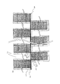
また図2は、本発明に係る太陽電池アレイを平面視した状態を示す外観図である。図2において、201は太陽電池アレイ、202は第1の太陽電池、203は第2の太陽電池、204は第3の太陽電池、205は第1の太陽電池架台、206は第2の太陽電池架台、207は第3の太陽電池架台、208は配線部材、209は第1の太陽電池架台と第3の太陽電池架台との間に設けられた通路である。
【0037】
図2に示すように、各太陽電池架台205、206、207上には、それぞれ太陽電池202、203、204が密着固定されており、上述したように、各太陽電池架台205、206、207は隣接する架台の一端部を利用して太陽電池の発光効率が最大となる傾斜角を形成するように調整して設置されている。すなわち、図2において、第1の太陽電池架台205の太陽電池設置面の右下端部と、第3の太陽電池架台207の太陽電池設置面の左下端部とに跨るように、第2の太陽電池架台206の太陽電池設置面と反対側の面の上両端部を重ねて設置することにより、縦横に配列された各太陽電池架台を傾斜させて設置することが可能である。
【0038】
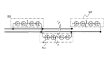
図3は、複数の太陽電池からなる太陽電池アレイの回路を示す説明図である。図3において、301は太陽電池アレイ、302は太陽電池、303は太陽電池ストリングである。
【0039】
上述したように、本発明に係る太陽電池アレイ301は、第1の太陽電池架台の一端部と第2の太陽電池架台の他端部、及び第3の太陽電池架台の一端部と第2の太陽電池架台の他端部とが接しているので、配線部材の本線を各太陽電池架台上に配することができ、各太陽電池ストリング303、303間を跨ぐ空中配線を大幅に削減することが可能となる。したがって、各配線部材を太陽電池架台上にしっかりと固定支持することができ、風などの外力による配線切れなどを防止することができる。また、各太陽電池ストリング303、303間における配線部分を固定するための配線固定用部材も別途設ける必要がないため、構成部品点数を大幅に削減することが可能となり、架台設置作業及び配線作業が容易となり、設置コストを大幅に削減することができる。その上、各太陽電池ストリング303、303間に通路を設けているので、メンテナンス性も向上させることができる。
【0040】
すなわち、本発明によれば、発電所向き太陽電池アレイとしての性能を落とすことなく、構成部材を大幅に削減するとともに、設置コストを大幅に削減し、メンテナンス性を向上させることができるものである。
【0041】
次に、本発明に係る太陽電池アレイの各構成要素について、さらに補足説明を行う。
【0042】
(太陽電池)
太陽電池の形態としては、結晶系光起電力素子、薄膜系光起電力素子、または多結晶系光起電力素子を用いた太陽電池が挙げられるが、特に限定されない。しかしながら、発電所に好適な太陽電池としては、活電部の一部が露出され簡易な被覆構造であることが望ましく、例えば、耐候性のあるステンレス鋼(SUS)などの金属基板に直接形成された光起電力素子において、その受光面側表面のみに被覆材を設け、直接架台等に接着することにより、最低限の耐候性を備えたメンテナンスし易い太陽電池が挙げられる。
【0043】
(光起電力素子)
本発明における光起電力素子については、特に限定されない。例えば、アモルファス/マイクロクリスタルシリコン光起電力素子、結晶シリコン光起電力素子、多結晶シリコン光起電力素子、アモルファスシリコン光起電力素子、銅インジウムセレナイド光起電力素子、化合物半導体光起電力素子等が挙げられる。例えば、可撓性基板を有する導電性基板上に、光変換部材としての半導体活性層などが形成されたものがある。このように可撓性を有する光起電力素子とすることにより、太陽電池のハンドリング中に生じる若干の撓みには問題なく対応できるため、太陽電池の信頼性をより一層確保できる。
【0044】
特に、太陽電池として、アモルファス/マイクロクリスタル型2層構造光起電力素子を用いることにより、フレキシブル性を有し、ハンドリング時など現場の施工作業が行い易いので、作業効率を向上させることが可能となり、設置コストを削減することができる。
【0045】
(被覆材)
被覆材は、光起電力素子を外部の汚れから保護したり、外部からの傷つき防止等の光起電力素子の耐候性を向上させる目的で用いられる。したがって、被覆材については、透明性、耐候性および耐汚染性が要求される。このような要求を満たし、好適に用いられる材料としては、例えば、フッ素樹脂、アクリル樹脂、ウレタン樹脂、シリコーン樹脂、ガラス、などが挙げられる。
【0046】
これらの材料を受光面側表面に設ける簡易被覆方法としては、フィルム化してラミネートする方法、コーティングによって設ける方法および粘着剤を配し接着する方法等がある。
【0047】
用途によって、表面のみに設けられる場合や裏面側にも設けられる場合があり、発電所に用いる場合は、コスト削減のために光起電力素子の耐候性を持たせるために必要である部分、即ち、少なくとも光起電力素子上には配し、光起電力素子間に設けられる配線部材等には配さない。
【0048】
特に好適な材料としては、光起電力素子に貼り付け可能な粘着性フィルムがある。中でも、基材にポリエチレンフィルム、粘着材にアクリル系粘着材を用いたポリエチレン保護シートが安価であり、耐候性に優れることから好ましい。
【0049】
(架台部材)
本発明における架台部材については、特に限定されない。しかし、耐候性を有し、材料コストを大幅に削減することが可能なコンクリート製の構造体が好ましく、中でも、板状のコンクリート板やコンクリートブロック等が好ましい。
【0050】
(配線部材)
本発明における太陽電池の配線部材(リード線)は、特に限定されるものではないが、導線が環境に対して一部が露出していても構わない。配線部材の一部が環境に対して露出していることにより、露出している配線部分では、どの部分でも結線することができるため配線接続作業を容易に行うことができ、作業効率を向上させることが可能となる。また、導通接続を行う接続部分が予め分かっている場合には、コネクタ部材等を設けておくと電気接続作業も効率化できる。
【0051】
(太陽電池ストリング)
太陽電池ストリングは、太陽電池を直列接続し所望の電圧を得るように構成する。この太陽電池の直列体を、一般的にストリングと呼ぶ。このストリングの幾つかを並列に接続し、発電規模が希望値となる太陽電池アレイを構成する。この太陽電池アレイに周辺の制御、保護、接続のための電力変換装置等の各構成部が加えられて、太陽光発電システムが構成される。
【0052】
【実施例】
以下、本発明の一実施例を説明するが、本発明は本実施例に限定されるものではない。
【0053】
本実施例は、少なくとも第1のアモルファス/マイクロクリスタル型2層構造光起電力素子を有する太陽電池(以下、「a−Si/μc光起電力素子を有する太陽電池」という。)、第2のa−Si/μc光起電力素子を有する太陽電池、及び第3のa−Si/μc光起電力素子を有する太陽電池を一組とする複数組の太陽電池により構成され、第1から第3のa−Si/μc光起電力素子を有する太陽電池がそれぞれ第1のコンクリート架台、第2のコンクリート架台、及び第3のコンクリート架台上に設置されている太陽電池アレイであって、第1の太陽電池架台と第3の太陽電池架台とが並列に配されており、第1のコンクリート架台と第3のコンクリートとの間に通路が形成され、この通路の一部を覆うように第2のコンクリート架台が配され、複数組の太陽電池にわたって導通接続されるI−V電線が、少なくとも第2のコンクリート架台上に支持されて固定されている太陽電池アレイの施工例である。
【0054】
図4は、本実施例の太陽電池アレイを示す概略図である。図4において、401は太陽電池アレイ、402は第1のa−Si/μc光起電力素子を有する太陽電池、403は第2のa−Si/μc光起電力素子を有する太陽電池、404は第3のa−Si/μc光起電力素子を有する太陽電池、405は第1のコンクリート架台、406は第2のコンクリート架台、407は第3のコンクリート架台、408及び413は第1のa−Si/μc光起電力素子を有する太陽電池と第2のa−Si/μc光起電力素子を有する太陽電池と第3のa−Si/μc光起電力素子を有する太陽電池とを導通接続するI−V電線、409は第1のコンクリート架台と第3のコンクリート架台との間に設けられた通路、410は太陽電池の出力端子、411はリングスリーブ、412はI−V電線をコンクリート架台上に固定するガルバリウム鋼板からなる配線固定部材である。
【0055】
また図5は、本実施例の太陽電池アレイを示す側面図である。図5において、501は太陽電池アレイ、502は第1のa−Si/μc光起電力素子を有する太陽電池、503は第2のa−Si/μc光起電力素子を有する太陽電池、504はコンクリート架台、505は第1のa−Si/μc光起電力素子を有する太陽電池と第2のa−Si/μc光起電力素子を有する太陽電池とを接続するI−V電線、506は505以外の光起電力素子間を接続するI−V電線、507は枕部材としてのコンクリートブロックである。
【0056】
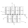
さらに図6は、本実施例の太陽電池アレイの回路を示す説明図である。図6において、601は太陽電池アレイ、602は第1のa−Si/μc光起電力素子を有する太陽電池、603は第2のa−Si/μc光起電力素子を有する太陽電池、604は第3のa−Si/μc光起電力素子を有する太陽電池、605は太陽電池ストリング、606は太陽電池ストリング間を接続するI−V電線である。
【0057】
これらの図に示すように、本実施例の太陽電池アレイは、第1のコンクリート架台と第2のコンクリート架台とが接するとともに、第3のコンクリート架台と第2のコンクリート架台とが接している。したがって、第2のコンクリート架台と、第1及び第3のコンクリート架台とが接している境界に沿ってI−V電線を固定することができるため、従来、架台間を跨いでいた空中配線を第2のコンクリート架台上に支持することが可能となる。その結果、風などの外力による配線切れや光起電力素子への損傷を防止することができる。
【0058】
また、別途に空中配線を固定するための配線固定用架台を設ける必要もないため、その分構成部品点数を大幅に削減することができ、配線固定作業も簡易化され、設置コストを大幅に削減することができる。
【0059】
さらに、太陽電池アレイ内には、第1のコンクリート架台と第3のコンクリート架台との間に通路が形成されるため、施工後にa−Si/μc光起電力素子を有する太陽電池の交換などのメンテナンス作業を行う際、光起電力素子を跨いだり、踏みつけたりすることなく、メンテナンス作業を行うことができ、光起電力素子の損傷を防止するとともに、その作業性を向上させることができる。また、メンテナンス作業時にa−Si/μc光起電力素子を有する太陽電池を損傷することもない。
【0060】
このように本発明によれば、太陽電池アレイとしての性能を低下させることなく、架台としての構成材料を大幅に削減することにより、太陽電池アレイの設置コストを大幅に削減することを可能とした。
【0061】
【発明の効果】
以上説明したように、本発明に係る太陽電池アレイによれば、配線固定用部材を削減するとともに、傾斜作成部材を大幅に削減することができ、しかも配線部材をも強固に支持固定することが可能となり、架台の作成及び設置作業を容易にすることができるという優れた効果を発揮する。
【図面の簡単な説明】
【図1】太陽電池、太陽電池架台、及び配線部材を有する本発明に係る太陽電池アレイの施工状況を示す概略図である。
【図2】本発明に係る太陽電池アレイを平面視した状態を示す外観図である。
【図3】本発明において、複数の太陽電池からなる太陽電池アレイの回路を示す説明図である。
【図4】実施例の太陽電池アレイの外観を示す概略図である。
【図5】実施例の太陽電池アレイを示す側面図である。
【図6】実施例の太陽電池アレイの回路を示す説明図である。
【符号の説明】
101 太陽電池アレイ
102 第1の太陽電池
103 第2の太陽電池
104 第3の太陽電池架台
105 第1の太陽電池架台
106 第2の太陽電池架台
107 第3の太陽電池架台
108 配線部材
109 通路
110 太陽電池の出力端子
111 配線接続部材
112 配線固定部材
113 配線部材
201 太陽電池アレイ
202 第1の太陽電池
203 第2の太陽電池
204 第3の太陽電池架台
205 第1の太陽電池架台
206 第2の太陽電池架台
207 第3の太陽電池架台
208 配線部材
209 通路
301 太陽電池アレイ
302 太陽電池
303 太陽電池ストリング
401 太陽電池アレイ
402 第1のa−Si/μc光起電力素子を有する太陽電池
403 第2のa−Si/μc光起電力素子を有する太陽電池
404 第3のa−Si/μc光起電力素子を有する太陽電池
405 第1のコンクリート架台
406 第2のコンクリート架台
407 第3のコンクリート架台
408 I−V電線
409 通路
410 太陽電池の出力端子
411 リングスリーブ
412 配線固定部材
413 I−V電線
501 太陽電池アレイ
502 第1のa−Si/μc光起電力素子を有する太陽電池
503 第2のa−Si/μc光起電力素子を有する太陽電池
504 コンクリート架台
505 I−V電線
506 I−V電線
507 枕部材(コンクリートブロック)
601 太陽電池アレイ
602 第1のa−Si/μc光起電力素子を有する太陽電池
603 第2のa−Si/μc光起電力素子を有する太陽電池
604 第3のa−Si/μc光起電力素子を有する太陽電池
605 太陽電池ストリング
606 I−V電線[0001]
TECHNICAL FIELD OF THE INVENTION
The present invention relates to a solar cell array that enables a wiring member to be firmly fixed by a method for constructing a solar cell array, and that can significantly reduce a wiring fixing base and an inclined forming member.
[0002]
[Prior art]
2. Description of the Related Art In recent years, awareness of protection of energy resources and environmental issues has been spreading worldwide. Above all, depletion of oil etc. and CO Two The concern over global warming associated with emissions is serious. Therefore, solar cell energy, which is a clean energy that can directly convert solar energy into electric power, has received great expectations.
[0003]
The current market for solar cell modules covers a variety of fields, such as for installation on architectural structures such as houses and buildings, and for portable use (for leisure). However, they are still expensive, which is the biggest barrier to their spread. As one of the measures, there is a method of integrally forming a product in a different field and a solar cell module to reduce the total cost.
[0004]
A typical example of a type of installation on a building structure is installation on a roof. In this case, a solar cell module of a roof-top type or a roof material integrated type has been spotlighted. The reason for this is that the roof material is not required as a separate member, so the total material cost for forming the roof can be reduced, and when installing it, it can be installed in the same way as normal roofing material installation. This is because the cost can be reduced, and the solar cell module can be installed on the roof at low cost as a total cost. In addition, the exterior is beautiful in harmony with the surrounding roof.
[0005]
As typified by this example, recent solar cell modules have increased their added value by integrating various different fields of products and solar cell modules. In other words, there is a part that can be shared with respect to the total material cost and total manufacturing cost of both, and by sharing that part, the shared cost can be significantly reduced when viewed as the total cost. Can be.
[0006]
On the other hand, what is attracting attention as a large market in the future is the market as a power plant. There is a movement to use solar power as a new energy source that replaces conventional energy.
[0007]
Every year, new power plants are being built to meet the increasing power consumption. In particular, the consumption of energy for cooling during the daytime in the daytime or in the daytime in summer is extremely large. These energies are called peak energies. Conventionally, power plants to be added have been thermal power generation, hydro power generation, nuclear power generation, and the like. However, recently, solar power generation, wind power generation, geothermal power generation, and the like have attracted attention as new energies in consideration of global warming measures, environmental protection measures, and the like. Since the peak energy time zone in summer or daytime is a time zone in which sunlight is irradiated, solar power generation having a characteristic of generating a large amount of energy during the peak energy time zone has attracted a great deal of attention.
[0008]
To use a solar cell module as a power source for a power plant, the current cost of generating solar cells is very high. Therefore, conventionally, the cost which can be shared has been created by integrating the products of different fields and the solar cell module, thereby reducing the total cost.
[0009]
However, when a solar cell module is considered as a power source of a power plant, only power is required, and other functions are not required. In other words, when used in combination with a conventional power source such as thermal power generation, it is very important that the power generation cost of the solar power generation and the power generation cost of the conventional power source are the same as those of the high value-added solar cell module. Has become an important factor. Of course, in consideration of the environment, it is ideal to use clean energy such as solar power, but if the cost is too high, it is not possible to replace the new energy source with the conventional energy source. It is possible. In this regard, it is difficult to use the solar cell module as a power source of the power plant at the current power generation cost of the solar cell module.
[0010]
Here, the above-mentioned power generation cost is as follows.
Power generation cost = (annual equipment cost + annual repair and maintenance cost + annual fuel cost) / annual power generation. The annual equipment cost is the total construction cost (initial investment) divided by the useful life of the power generation system. However, in this case, interest rates must be taken into account. The annual repair / maintenance cost is the total annual cost for maintaining the power generation system. Fuel cost is the total annual cost spent on fuel required to operate the equipment of the power generation system.
[0011]
Solar power generation systems that use solar cell modules use inexhaustible solar energy and do not require annual fuel costs. Repair and maintenance costs are not too high. The largest factor in generating power in a solar power system is the annual equipment cost. That is, the watt cost of the solar cell module is high.
[0012]
In such a situation, in order to spread the photovoltaic power generation and use it as a power source of a power plant, it is indispensable to greatly reduce the cost of the photovoltaic power generation. That is, it is indispensable to reduce the wattage cost of the solar cell module and the installation cost thereof, and to reduce the power generation cost of the conventional power generation system to a competitive power generation cost.
[0013]
Further, the cost of the above-described solar cell module will be described. Conventional power generation costs are designed to be used and touched by ordinary consumers who are not solar cell or electricity experts. However, in such a method, a large amount of materials are required to enhance safety, so that the cost of raw materials is high, and in the manufacturing process, a heat-press bonding step is required, so that productivity is reduced, and the number of manufacturing steps (man-hour) is reduced. ) Also increases production costs. That is, the total power generation cost increases. Thus, as long as the solar cell module is produced by the conventional method, there is a limit in reducing the watt cost of the solar cell module.
[0014]
In the case of a solar cell module used in a power plant, it is used in a controlled environment. Here, the management environment is a situation managed by a specialist in electricity or a solar cell module, and means a place where there is no danger of a general person other than a handler entering. In this management environment, measures such as providing a fence or a fence around the solar cell module enclosure or providing a lock at an entrance / exit are taken. In addition, the operator is placed in a situation where regular maintenance is possible.
[0015]
Conventionally, when performing maintenance of a photovoltaic power generation system in which a solar cell is installed on a roof or the like, it was possible to trample on a roof material or a solar cell module, so that the operation could be performed without any problem. However, the ground-mounted solar power generation system for large-scale power plants, etc., is a specific solar cell module with minimal constituent materials, so it is difficult to trample or walk on the gantry. May be destroyed. Therefore, a passage is usually provided between the frames. In such a case, a wiring fixing base for fixing the wiring member is required for the wiring material straddling the mounts in order to prevent disconnection of the wiring due to external force such as wind or ground fault of the wiring to the ground. In addition, the installation cost was increased and the work efficiency was reduced. Many photovoltaic power generation devices using such a gantry are known.
[0016]
For example, Patent Literature 1 discloses a solar cell device in which a plurality of solar cell elements capable of generating electric power by light from the front and back surfaces are electrically connected to each other or a device for guiding light to the back surface side of the solar cell device between solar cell devices. A solar cell device provided with a light opening is disclosed.
[0017]
[Patent Document 1]
Japanese Patent Application Laid-Open No. H11-340491
[0018]
[Problems to be solved by the invention]
However, in the solar cell device disclosed in Patent Literature 1, the solar cell arrays installed on the pedestal are arranged in a row at intervals, and a passage at the time of maintenance is also secured by leaving an interval, thereby improving workability. Although it may be possible to improve the space, the electrical wiring member for electrically connecting the gantry becomes an aerial wiring or crawls on the ground by providing an interval.
[0019]
In the case of aerial wiring, the possibility of disconnection due to vibrations such as wind may occur.To prevent this, a wiring fixing stand is required to firmly fix the wiring, and the installation cost is accordingly reduced. The problem of a large increase arises. In addition, when the wiring material is laid on the ground, if a live part is present partially, there is a risk of ground fault because it is in direct contact with the ground, and to prevent this, a sufficient insulating structure is taken, or A fixing gantry having insulating properties must be provided, which causes a problem that the material cost increases accordingly.
[0020]
In such a method, a large number of installation materials are required, and accordingly, the installation work is also increased, so that the installation cost is high.
[0021]
The present invention has been made in view of the above circumstances, and an object of the present invention is to provide a solar cell array capable of greatly reducing installation materials and facilitating creation and installation work of a gantry. is there.
[0022]
[Means for Solving the Problems]
In order to achieve the above object, a solar cell array according to the present invention includes at least a first solar cell, a second solar cell, and a plurality of sets of solar cells each including a third solar cell, A solar cell array in which each of the solar cells is installed on a first solar cell gantry, a second solar cell gantry, and a third solar cell gantry,
The first solar cell mount and the third solar cell mount are arranged in parallel, and the second solar cell mount is arranged so as to cover a part between the first solar cell mount and the third solar cell mount. A wiring member that is provided and that is conductively connected across a plurality of sets of solar cells is supported and fixed on at least the second solar cell gantry.
[0023]
In the above-mentioned solar cell array, it is preferable that the first solar cell mount and the third solar cell mount are separated from each other with a passage therebetween.
[0024]
In addition, one end of the solar cell installation surface of the first solar cell mount and one end of the solar cell installation surface of the third solar cell mount are provided on the opposite side of the solar cell installation surface of the second solar cell mount. It is preferable that the other end of the surface is arranged to be in contact with the surface.
[0025]
Further, it is preferable that the solar cell mount is a concrete structure.
[0026]
And a part of the live part of a solar cell may be exposed.
[0027]
In addition, it is preferable to use an amorphous / microcrystalline silicon type two-layer structure photovoltaic element as the solar cell.
[0028]
BEST MODE FOR CARRYING OUT THE INVENTION
Hereinafter, embodiments of the present invention will be described with reference to the drawings, but the present invention is not limited to the embodiments.
[0029]
FIG. 1 is a schematic view showing a construction state of a solar cell array according to the present invention having a solar cell, a solar cell gantry, and a wiring member. In FIG. 1, 101 is a solar cell array, 102 is a first solar cell, 103 is a second solar cell, 104 is a third solar cell, 105 is a first solar cell stand, and 106 is a second solar cell. A stand, 107 is a third solar cell stand, 108 is a wiring member, 109 is a passage provided between the first solar cell stand and the third solar cell stand, 110 is a terminal of the solar cell, 111 is a wiring The connection member 112 is a wiring fixing member.
[0030]
As shown in FIG. 1, a solar cell array 101 according to the present invention includes a plurality of sets of solar cells each including at least a first solar cell 102, a second solar cell 103, and a third solar cell 104. The solar cells 102, 103, and 104 are configured on a first solar cell stand 105, a second solar cell stand 106, and a third solar cell stand 107, respectively. The first solar cell base 105 and the third solar cell base 107 are arranged in parallel with a space therebetween, and a passage 109 is formed between them. A second solar cell stand 106 is provided. That is, a plurality of solar cell racks for installing the solar cells are arranged in a plurality of rows in parallel with the passage 109 therebetween, and the solar cells mounted on each solar cell rack as a whole are staggered vertically or horizontally or in a checkered pattern. It is installed so as to exhibit a shape.
[0031]
In the present embodiment, one end of the solar cell installation surface of the first solar cell mount 105 and one end of the solar cell installation surface of the third solar cell mount 107 are connected to the solar cell of the second solar cell mount 106. It is installed so that the other end of the surface opposite to the installation surface contacts. In this arrangement, at least the first solar cell 102, the second solar cell 103, and the third solar cell 104 are described as one set. Each of the solar cell gantry installed so as to assume the shape is configured in this manner, so that each of the solar cell gantry is arranged to be inclined. That is, one end of the solar cell installation surface of the first solar cell stand 105 and the third solar cell stand 107 is brought into contact with the other end of the surface of the second solar cell stand 106 opposite to the solar cell installation surface. By installing in such a manner, it is possible to install each of the solar cell mounts arranged vertically and horizontally at an inclination, and it is possible to improve the power generation efficiency. Therefore, since the solar cell array 101 of the present embodiment is constructed in the south direction, there is no need to provide a separate pillow member to form a slope, except for the gantry located at the northernmost side, reducing the material and reducing the work. It can be greatly simplified.
[0032]
Each solar cell mount is configured by a concrete structure. Since the solar cell gantry is a concrete structure, the gantry can be easily arranged, the electric insulation is good at the time of drying, and the material cost can be significantly reduced.
[0033]
By arranging the solar cell frame in this manner, it is possible to reduce the number of inclined members, so that the material cost can be significantly reduced. However, in order to protect the wiring members from strong winds even when such construction is performed, it is necessary to fix and support the wiring members arranged between the solar cell mounts.
[0034]
Therefore, in the present embodiment, the wiring member 108 for electrically connecting the first solar cell 102, the second solar cell 103, and the third solar cell 104 in parallel or in series is connected to at least the second solar cell base 106. Supported. Specifically, in the wiring member 108, the branch line connected via the wiring connection member 111 is conductively connected to each of the solar cells 102, 103, and 104, and the main line of the wiring member 108 is connected to the first solar cell base. 105 and the third solar cell gantry 107 and the second solar cell gantry 106 are arranged along a boundary line between the first solar cell gantry 105 and the third solar cell gantry 107 by the wiring fixing member 112. It is fixed and supported on the second solar cell stand 106.
[0035]
Therefore, the wiring member 108 can be firmly supported and fixed over the first solar cell gantry 105, the second solar cell gantry 106, and the third solar cell gantry 107, and there is no need to perform aerial wiring. The cause of the disconnection of the wiring due to external force such as wind can be eliminated. In particular, since the wiring portion that straddles the passage 109 between the first solar cell gantry 105 and the third solar cell gantry 107 is fixed on the second solar cell gantry 106, the wiring fixing separately fixes the aerial wiring. It is not necessary to provide any additional members, so that the material cost can be greatly reduced, the operation can be simplified, and the installation cost can be significantly reduced.
[0036]
FIG. 2 is an external view showing the solar cell array according to the present invention in a plan view. 2, 201 is a solar cell array, 202 is a first solar cell, 203 is a second solar cell, 204 is a third solar cell, 205 is a first solar cell stand, and 206 is a second solar cell. A stand, 207 is a third solar cell stand, 208 is a wiring member, and 209 is a passage provided between the first solar cell stand and the third solar cell stand.
[0037]
As shown in FIG. 2, the solar cells 202, 203, and 204 are closely fixed on the respective solar cell stands 205, 206, and 207. As described above, each of the solar cell stands 205, 206, and 207 is It is installed so as to form an inclination angle at which the luminous efficiency of the solar cell is maximized by using one end of an adjacent gantry. That is, in FIG. 2, the second solar cell extends over the lower right end of the solar cell installation surface of the first solar cell rack 205 and the lower left end of the solar cell installation surface of the third solar cell rack 207. By arranging the upper and lower ends of the surface opposite to the solar cell installation surface of the battery gantry 206 in an overlapping manner, it is possible to install each of the solar cell gantry arranged vertically and horizontally at an angle.
[0038]
FIG. 3 is an explanatory diagram illustrating a circuit of a solar cell array including a plurality of solar cells. In FIG. 3, reference numeral 301 denotes a solar cell array, 302 denotes a solar cell, and 303 denotes a solar cell string.
[0039]
As described above, the solar cell array 301 according to the present invention includes one end of the first solar cell mount, the other end of the second solar cell mount, and one end of the third solar cell mount and the second end. Since the other end of the solar cell gantry is in contact with the solar cell gantry, the main line of the wiring member can be arranged on each solar cell gantry, and the aerial wiring that straddles between the solar cell strings 303 can be significantly reduced. It becomes possible. Therefore, each wiring member can be firmly fixed and supported on the solar cell frame, and disconnection of the wiring due to external force such as wind can be prevented. Further, since it is not necessary to separately provide a wiring fixing member for fixing the wiring portion between the respective solar cell strings 303, 303, the number of components can be significantly reduced, and the work of installing the gantry and the wiring work can be reduced. It becomes easy and installation cost can be greatly reduced. In addition, since a passage is provided between each of the solar cell strings 303, 303, maintainability can be improved.
[0040]
That is, according to the present invention, it is possible to greatly reduce the number of components, greatly reduce the installation cost, and improve the maintainability without deteriorating the performance as a solar cell array for a power plant. .
[0041]
Next, each component of the solar cell array according to the present invention will be further supplementarily described.
[0042]
(Solar cells)
Examples of the form of the solar cell include, but are not particularly limited to, a solar cell using a crystalline photovoltaic element, a thin-film photovoltaic element, or a polycrystalline photovoltaic element. However, as a solar cell suitable for a power plant, it is desirable that a part of the live part is exposed and a simple covering structure is used. For example, the solar cell is formed directly on a metal substrate such as stainless steel (SUS) having weather resistance. In such a photovoltaic element, a solar cell having minimum weather resistance and easy maintenance is provided by providing a coating material only on the light receiving surface side surface and directly bonding the coating material to a mount or the like.
[0043]
(Photovoltaic element)
The photovoltaic element in the present invention is not particularly limited. For example, amorphous / microcrystalline silicon photovoltaic devices, crystalline silicon photovoltaic devices, polycrystalline silicon photovoltaic devices, amorphous silicon photovoltaic devices, copper indium selenide photovoltaic devices, compound semiconductor photovoltaic devices, etc. Is mentioned. For example, there is a substrate in which a semiconductor active layer or the like as a light conversion member is formed on a conductive substrate having a flexible substrate. By using a photovoltaic element having flexibility in this way, slight deflection occurring during handling of the solar cell can be dealt with without any problem, so that the reliability of the solar cell can be further secured.
[0044]
In particular, by using an amorphous / micro-crystal type two-layer structure photovoltaic element as a solar cell, it has flexibility and can easily perform on-site construction work such as handling, so it is possible to improve work efficiency. , Installation costs can be reduced.
[0045]
(Coating material)
The coating material is used for the purpose of protecting the photovoltaic element from external dirt and improving the weather resistance of the photovoltaic element such as prevention of external damage. Therefore, the coating material is required to have transparency, weather resistance and stain resistance. Materials that satisfy such requirements and are preferably used include, for example, fluorine resin, acrylic resin, urethane resin, silicone resin, glass, and the like.
[0046]
As a simple coating method of providing these materials on the light-receiving surface side surface, there are a method of forming a film and laminating, a method of providing by coating, a method of arranging an adhesive and bonding.
[0047]
Depending on the application, it may be provided only on the front surface or on the back surface side, and when used in a power plant, a portion necessary to impart weatherability of the photovoltaic element for cost reduction, that is, , At least on the photovoltaic elements, but not on the wiring members provided between the photovoltaic elements.
[0048]
A particularly suitable material is an adhesive film that can be attached to a photovoltaic element. Among them, a polyethylene protective sheet using a polyethylene film as a base material and an acrylic adhesive as an adhesive is preferable because it is inexpensive and has excellent weather resistance.
[0049]
(Mounting member)
The gantry member in the present invention is not particularly limited. However, a concrete structure having weather resistance and capable of significantly reducing material costs is preferable, and a plate-like concrete plate or concrete block is particularly preferable.
[0050]
(Wiring members)
The wiring member (lead wire) of the solar cell in the present invention is not particularly limited, but a part of the conductive wire may be exposed to the environment. Since a part of the wiring member is exposed to the environment, any part of the exposed wiring part can be connected, so that the wiring connection work can be easily performed and the work efficiency is improved. It becomes possible. In addition, when the connection portion for conducting connection is known in advance, providing a connector member or the like can increase the efficiency of the electrical connection work.
[0051]
(Solar cell string)
The solar cell string is configured such that solar cells are connected in series to obtain a desired voltage. This series of solar cells is generally called a string. Some of these strings are connected in parallel to form a solar cell array having a desired power generation scale. Each component such as a power converter for controlling, protecting, and connecting the periphery is added to this solar cell array, and a solar power generation system is configured.
[0052]
【Example】
Hereinafter, an embodiment of the present invention will be described, but the present invention is not limited to the embodiment.
[0053]
In the present embodiment, a solar cell having at least a first amorphous / microcrystal type two-layer structure photovoltaic element (hereinafter, referred to as a “solar cell having an a-Si / μc photovoltaic element”) and a second cell are described. a plurality of sets of solar cells each including a solar cell having an a-Si / μc photovoltaic element and a solar cell having a third a-Si / μc photovoltaic element; A solar cell array having the a-Si / μc photovoltaic element of (a) is mounted on a first concrete gantry, a second concrete gantry, and a third concrete gantry, respectively. The solar cell gantry and the third solar cell gantry are arranged in parallel, a passage is formed between the first concrete gantry and the third concrete, and a second passage is formed so as to cover a part of the passage. Concrete mounting Provided that, I-V wire is conductively connected over a plurality of sets of solar cells, a construction example of a solar cell array is fixedly supported on at least a second concrete frame.
[0054]
FIG. 4 is a schematic diagram illustrating the solar cell array according to the present embodiment. In FIG. 4, 401 is a solar cell array, 402 is a solar cell having a first a-Si / μc photovoltaic element, 403 is a solar cell having a second a-Si / μc photovoltaic element, and 404 is A solar cell having a third a-Si / μc photovoltaic element, 405 is a first concrete mount, 406 is a second concrete mount, 407 is a third concrete mount, 408 and 413 are first a- The solar cell having the Si / μc photovoltaic element, the solar cell having the second a-Si / μc photovoltaic element, and the solar cell having the third a-Si / μc photovoltaic element are electrically connected. IV electric wire, 409 is a passage provided between the first concrete mount and the third concrete mount, 410 is an output terminal of a solar cell, 411 is a ring sleeve, 412 is an IV electric wire on the concrete mount. A wiring fixing member made of Galvalume steel plate for fixing.
[0055]
FIG. 5 is a side view showing the solar cell array of this embodiment. In FIG. 5, 501 is a solar cell array, 502 is a solar cell having a first a-Si / μc photovoltaic element, 503 is a solar cell having a second a-Si / μc photovoltaic element, and 504 is A concrete mount, 505 is an IV electric wire connecting a solar cell having a first a-Si / μc photovoltaic element and a solar cell having a second a-Si / μc photovoltaic element, and 506 is 505 Reference numeral 507 denotes a concrete block as a pillow member, which connects the other photovoltaic elements to each other.
[0056]
FIG. 6 is an explanatory diagram showing a circuit of the solar cell array according to the present embodiment. In FIG. 6, 601 is a solar cell array, 602 is a solar cell having a first a-Si / μc photovoltaic element, 603 is a solar cell having a second a-Si / μc photovoltaic element, and 604 is A solar cell having a third a-Si / μc photovoltaic element, 605 is a solar cell string, and 606 is an IV electric wire connecting between the solar cell strings.
[0057]
As shown in these figures, in the solar cell array according to the present embodiment, the first concrete gantry and the second concrete gantry are in contact with each other, and the third concrete gantry and the second concrete gantry are in contact with each other. Therefore, the IV electric wire can be fixed along the boundary where the second concrete mount and the first and third concrete mounts are in contact with each other. 2 can be supported on a concrete gantry. As a result, it is possible to prevent disconnection of wiring due to external force such as wind and damage to the photovoltaic element.
[0058]
Also, there is no need to provide a separate wiring fixing base for fixing the aerial wiring, which can greatly reduce the number of component parts, simplifying wiring fixing work and greatly reducing installation costs. can do.
[0059]
Further, since a passage is formed between the first concrete gantry and the third concrete gantry in the solar cell array, it is necessary to replace the solar cell having the a-Si / μc photovoltaic element after the construction. When performing the maintenance work, the maintenance work can be performed without straddling or stepping on the photovoltaic element, and the photovoltaic element can be prevented from being damaged and the workability can be improved. Further, the solar cell having the a-Si / μc photovoltaic element is not damaged during the maintenance work.
[0060]
As described above, according to the present invention, it is possible to greatly reduce the installation cost of the solar cell array by greatly reducing the constituent materials as the stand without lowering the performance as the solar cell array. .
[0061]
【The invention's effect】
As described above, according to the solar cell array of the present invention, the number of wiring fixing members can be reduced, the number of inclined members can be significantly reduced, and the wiring members can be firmly supported and fixed. This makes it possible to facilitate the creation and installation of the gantry.
[Brief description of the drawings]
FIG. 1 is a schematic diagram showing a construction state of a solar cell array according to the present invention having a solar cell, a solar cell frame, and a wiring member.
FIG. 2 is an external view showing the solar cell array according to the present invention in a plan view.
FIG. 3 is an explanatory diagram showing a circuit of a solar cell array including a plurality of solar cells in the present invention.
FIG. 4 is a schematic view showing the appearance of a solar cell array according to an example.
FIG. 5 is a side view showing a solar cell array according to an example.
FIG. 6 is an explanatory diagram showing a circuit of a solar cell array according to an example.
[Explanation of symbols]
101 solar cell array
102 First solar cell
103 Second solar cell
104 Third solar cell stand
105 First solar cell stand
106 Second solar cell stand
107 Third solar cell stand
108 Wiring member
109 passage
110 Output terminal of solar cell
111 Wiring connection member
112 Wiring fixing member
113 Wiring member
201 Solar cell array
202 First solar cell
203 Second solar cell
204 Third Solar Cell Stand
205 First Solar Cell Stand
206 Second solar cell stand
207 Third solar cell mount
208 Wiring member
209 passage
301 solar array
302 solar cell
303 solar cell string
401 solar cell array
402 Solar cell having first a-Si / μc photovoltaic element
403 Solar cell having second a-Si / μc photovoltaic element
404 Solar cell having third a-Si / μc photovoltaic element
405 First concrete mount
406 Second concrete mount
407 Third concrete mount
408 IV electric wire
409 passage
410 Output terminal of solar cell
411 Ring sleeve
412 Wiring fixing member
413 IV electric wire
501 Solar array
502 Solar Cell Having First a-Si / μc Photovoltaic Element
503 Solar cell having second a-Si / μc photovoltaic element
504 concrete frame
505 IV electric wire
506 IV electric wire
507 Pillow material (concrete block)
601 solar array
602 Solar cell having first a-Si / μc photovoltaic element
603 Solar cell having second a-Si / μc photovoltaic element
604 Solar cell having third a-Si / μc photovoltaic element
605 solar cell string
606 IV electric wire