JP2004192105A - Connection device of storage device and computer system including it - Google Patents
Connection device of storage device and computer system including it Download PDFInfo
- Publication number
- JP2004192105A JP2004192105A JP2002356477A JP2002356477A JP2004192105A JP 2004192105 A JP2004192105 A JP 2004192105A JP 2002356477 A JP2002356477 A JP 2002356477A JP 2002356477 A JP2002356477 A JP 2002356477A JP 2004192105 A JP2004192105 A JP 2004192105A
- Authority
- JP
- Japan
- Prior art keywords
- storage device
- control
- instruction
- function
- volume
- Prior art date
- Legal status (The legal status is an assumption and is not a legal conclusion. Google has not performed a legal analysis and makes no representation as to the accuracy of the status listed.)
- Pending
Links
Images


Classifications
-
- G—PHYSICS
- G06—COMPUTING; CALCULATING OR COUNTING
- G06F—ELECTRIC DIGITAL DATA PROCESSING
- G06F3/00—Input arrangements for transferring data to be processed into a form capable of being handled by the computer; Output arrangements for transferring data from processing unit to output unit, e.g. interface arrangements
- G06F3/06—Digital input from, or digital output to, record carriers, e.g. RAID, emulated record carriers or networked record carriers
- G06F3/0601—Interfaces specially adapted for storage systems
- G06F3/0628—Interfaces specially adapted for storage systems making use of a particular technique
- G06F3/0662—Virtualisation aspects
- G06F3/0665—Virtualisation aspects at area level, e.g. provisioning of virtual or logical volumes
-
- G—PHYSICS
- G06—COMPUTING; CALCULATING OR COUNTING
- G06F—ELECTRIC DIGITAL DATA PROCESSING
- G06F3/00—Input arrangements for transferring data to be processed into a form capable of being handled by the computer; Output arrangements for transferring data from processing unit to output unit, e.g. interface arrangements
- G06F3/06—Digital input from, or digital output to, record carriers, e.g. RAID, emulated record carriers or networked record carriers
- G06F3/0601—Interfaces specially adapted for storage systems
- G06F3/0602—Interfaces specially adapted for storage systems specifically adapted to achieve a particular effect
- G06F3/0604—Improving or facilitating administration, e.g. storage management
- G06F3/0605—Improving or facilitating administration, e.g. storage management by facilitating the interaction with a user or administrator
-
- G—PHYSICS
- G06—COMPUTING; CALCULATING OR COUNTING
- G06F—ELECTRIC DIGITAL DATA PROCESSING
- G06F3/00—Input arrangements for transferring data to be processed into a form capable of being handled by the computer; Output arrangements for transferring data from processing unit to output unit, e.g. interface arrangements
- G06F3/06—Digital input from, or digital output to, record carriers, e.g. RAID, emulated record carriers or networked record carriers
- G06F3/0601—Interfaces specially adapted for storage systems
- G06F3/0602—Interfaces specially adapted for storage systems specifically adapted to achieve a particular effect
- G06F3/0604—Improving or facilitating administration, e.g. storage management
- G06F3/0607—Improving or facilitating administration, e.g. storage management by facilitating the process of upgrading existing storage systems, e.g. for improving compatibility between host and storage device
-
- G—PHYSICS
- G06—COMPUTING; CALCULATING OR COUNTING
- G06F—ELECTRIC DIGITAL DATA PROCESSING
- G06F3/00—Input arrangements for transferring data to be processed into a form capable of being handled by the computer; Output arrangements for transferring data from processing unit to output unit, e.g. interface arrangements
- G06F3/06—Digital input from, or digital output to, record carriers, e.g. RAID, emulated record carriers or networked record carriers
- G06F3/0601—Interfaces specially adapted for storage systems
- G06F3/0628—Interfaces specially adapted for storage systems making use of a particular technique
- G06F3/0655—Vertical data movement, i.e. input-output transfer; data movement between one or more hosts and one or more storage devices
- G06F3/0659—Command handling arrangements, e.g. command buffers, queues, command scheduling
-
- G—PHYSICS
- G06—COMPUTING; CALCULATING OR COUNTING
- G06F—ELECTRIC DIGITAL DATA PROCESSING
- G06F3/00—Input arrangements for transferring data to be processed into a form capable of being handled by the computer; Output arrangements for transferring data from processing unit to output unit, e.g. interface arrangements
- G06F3/06—Digital input from, or digital output to, record carriers, e.g. RAID, emulated record carriers or networked record carriers
- G06F3/0601—Interfaces specially adapted for storage systems
- G06F3/0628—Interfaces specially adapted for storage systems making use of a particular technique
- G06F3/0662—Virtualisation aspects
- G06F3/0664—Virtualisation aspects at device level, e.g. emulation of a storage device or system
-
- G—PHYSICS
- G06—COMPUTING; CALCULATING OR COUNTING
- G06F—ELECTRIC DIGITAL DATA PROCESSING
- G06F3/00—Input arrangements for transferring data to be processed into a form capable of being handled by the computer; Output arrangements for transferring data from processing unit to output unit, e.g. interface arrangements
- G06F3/06—Digital input from, or digital output to, record carriers, e.g. RAID, emulated record carriers or networked record carriers
- G06F3/0601—Interfaces specially adapted for storage systems
- G06F3/0668—Interfaces specially adapted for storage systems adopting a particular infrastructure
- G06F3/067—Distributed or networked storage systems, e.g. storage area networks [SAN], network attached storage [NAS]
Abstract
Description
【0001】
【発明の属する技術分野】
本発明は、ホストコンピュータと複数の記憶装置と接続する技術に関し、特に、ディスクアレイなどの記憶装置がユーザに提供する様々な機能の制御に関する。
【0002】
【従来の技術】
近年、ディスクアレイに代表されるコンピュータの記憶装置のインテリジェント化が進んでいる。例えば、ディスクアレイ装置が提供するミラー機能は、ホストコンピュータがディスクアレイ装置内の記憶領域のデータを更新すると、あらかじめ決められた別の記憶領域にもその更新データを自動的に書き込む。ミラーの停止を指示することにより、その時点での記憶データを保存し、バックアップ等の用途に使用することができる。更新データの別領域への書き込みはディスクアレイ装置内のコントローラによって実行されるため、ホストコンピュータに負荷がかからず、高速な入出力処理が可能となる(例えば、特許文献1参照)。
【0003】
一方、システム内の記憶装置の数が増え、種類の異なる記憶装置が混在するということが起こっている。即ち、異なるプロトコルを持った記憶装置が混在することになる。ここで、機能とは記憶装置をミラーすることやスナップショットを取ることなどを言い、機能制御とはホストコンピュータが記憶装置にこれらの機能を実現させるよう制御することである。
【0004】
ホストコンピュータは、ディスクアレイが提供する機能制御インタフェースにアクセスし、あらかじめ定義された記憶装置に固有のプロトコルで指示を送ることにより、機能を制御する。機能制御インタフェースは、In−bandのSCSIコマンドや、LAN経由のTCP/IP通信など、さまざまな形態で実現できる(例えば、特許文献2参照)。
【0005】
また、複数のホストコンピュータと記憶装置をネットワークで接続するストレージエリアネットワーク(SAN: Storage Area Network)の普及が進んでいる。SANはファイバチャネルに代表されるようなデータ入出力専用の高速ネットワークであり、コンピュータの入出力性能を向上することができる。さらに、SANで接続されたコンピュータ群が1つの記憶装置を共用したり、逆に1つのコンピュータが複数の記憶装置にアクセスしたりできるなど、多様な記憶領域の利用が可能となる。最近では、記憶装置/記憶領域の共有を実現するだけでなく、記憶装置が提供する記憶領域(ディスクボリューム)を結合、あるいは分割して仮想的な記憶領域(仮想ボリューム)をホストコンピュータに提供するストレージバーチャライゼーション(Storage Virtualization)の技術も導入されはじめ、より柔軟な記憶領域の管理が可能となっている。
【0006】
【特許文献1】
米国特許第5,845,295号明細書
【特許文献2】
米国特許第5,867,736号明細書
【0007】
【発明が解決しようとする課題】
SAN環境など、複数の異なる種類の記憶装置が混在するコンピュータシステムにおいて、記憶装置が提供するインテリジェントな機能を利用する場合、ホストコンピュータは制御対象となるディスクアレイの種類を識別し、各記憶装置に固有のインタフェースで機能制御の指示を送る必要がある。同じ機能の制御でも装置毎に異なる制御プログラムをホストコンピュータ内に用意して使い分けなければならず、制御が複雑化する。
【0008】
また、ストレージバーチャライゼーションにおいては、記憶装置が提供する機能を利用して仮想ボリューム単位でインテリジェントな機能を実現することが考えられるが、その際、仮想ボリュームが複数のディスクボリュームから構成されていると、ディスクボリューム毎に機能の制御を指示する必要がある。そのため、ホストコンピュータは仮想ボリュームの実際の記憶領域を提供する装置を識別し、各装置固有の制御インタフェースを使用する必要があるため制御が複雑化する。
【0009】
本発明の目的は、異なる種類の記憶装置のさまざまな機能を制御するために、装置の種類に依存しない共通の制御インタフェースを提供し、制御の簡単化を実現することである。
【0010】
【課題を解決するための手段】
本発明は、記憶装置の機能を制御するための共通インタフェースをコンピュータシステム内のバーチャライゼーションサーバやスイッチに設け、記憶装置の種類に依存しない機能制御方法を提供する。ホストコンピュータは、制御の対象となる記憶装置の種類にかかわらず、あらかじめ定義されたプロトコルで共通インタフェースに機能制御の指示を送る。共通インタフェースを提供する装置は、ホストコンピュータが認識する記憶領域と、記憶装置が提供する記憶領域の対応関係を管理する。また、共通インタフェースのプロトコルを各装置に固有のプロトコルに変換する手段を備え、各記憶装置に固有のインタフェースを介して機能制御を実現する手段をもつ。
【0011】
共通インタフェースを提供する装置が機能制御の指示を受け取ると、指示の対象となる記憶領域と、それを提供している記憶装置を解釈する。例えば、指示が、ある仮想ボリュームに対するものである場合は、仮想ボリュームを構成するディスクボリュームが指示の対象となる。指示の対象となる記憶領域を提供する記憶装置の種類を識別し、その装置に固有の機能制御インタフェースを介して機能制御を指示する。各装置に固有のインタフェースはインタフェースサーバで隠蔽され、ホストコンピュータは制御対象の装置の種類を意識することなく、共通のインタフェースを利用して機能を制御することが可能となる。ホストコンピュータは、複数のインタフェースに対応し、それぞれを使い分ける必要がなくなるため、制御の簡単化が実現できる。
【0012】
【発明の実施の形態】
第一の実施の形態
本実施形態は、ファイバチャネルで接続され、異なる機能制御インタフェースを持つ2つのディスクアレイ装置が提供する記憶領域をバーチャライゼーションサーバで仮想化するストレージバーチャライゼーション環境において、ディスクアレイ装置のミラー機能を用いて実現された仮想ボリュームのミラー機能を、バーチャライゼーションサーバが提供する共通インタフェースを利用して制御する例である。
【0013】
(1) システムの構成
図1に本実施形態の全体構成を示す。
【0014】
2台のホストコンピュータ1101、1201および2台のディスクアレイ1401、1501があり、それぞれのファイバチャネルインタフェース1102、1202、1402、1502とファイバチャネルケーブル1314〜1317によりバーチャライゼーションサーバ1301のファイバチャネルインタフェース1302、1303、1307、1308に接続されている。ホストコンピュータから記憶装置へのデータ入出力は、これらのファイバチャネルケーブル上の標準的なSCSIプロトコルで実現される。以下の説明では、ホストコンピュータやディスクアレイ装置がバーチャライゼーションサーバと直接接続されているが、本発明は通信媒体や接続形態に依存しないため、スイッチを経由した接続やファイバチャネル以外のSCSIやIPネットワークなど、他の通信媒体やプロトコルを用いた構成にも適用可能である。
【0015】
ホストコンピュータ1101のメモリ1104内には、仮想ボリュームの機能制御を指示するための仮想ボリューム機能制御プログラム1106があり、CPU1103により実行される。仮想ボリューム機能制御プログラム1106は、ディスクアレイの機能制御指示を送出するホストコンピュータにあらかじめインストールされている。仮想ボリューム機能制御プログラム1106は、後述するように、制御する機能や制御対象となる仮想ボリュームなどの必要な情報をバーチャライゼーションサーバ1301が提供する共通インタフェース(ホストコンピュータから見て共通インタフェースとして供給される仮想ボリューム)に送り、機能制御を指示する。ホストコンピュータ1201も同様の構成を持つ。
【0016】
ディスクアレイ1401では、コントローラ1404内の制御プログラム1407が全体の動作を統括する。制御プログラム1407は、ディスクボリューム1405および1406をホストコンピュータの記憶領域として提供する通常のディスクアレイ機能に加え、ミラー機能やスナップショット機能などのさまざまなインテリジェント機能を提供する。ディスクアレイ1501も1401と同様の構成を持ち、ミラー機能を含むインテリジェント機能を提供する。
【0017】
バーチャライゼーションサーバ1301は、全体の動作をボリューム仮想化プログラム1309が制御し、ストレージバーチャライゼーション機能を提供する。記憶領域仮想化の実現方法の詳細は本発明の主眼ではないので、簡単に説明する。ディスクアレイが提供する複数のディスクボリュームから1つの仮想ボリュームを作成する場合、各ディスクボリュームの記憶領域を結合し、1つの仮想ボリュームに見せる。各ディスクボリュームのアドレス空間が仮想ボリュームのアドレス空間の一部にマッピングされ、1つの連続したアドレス空間を実現する。バーチャライゼーションサーバ1301内の制御プログラムが、仮想ボリュームとそれを構成する実際のディスクボリュームの対応関係、および仮想ボリュームのアドレス空間と実際のディスクボリュームのアドレス空間の対応関係を管理する。仮想ボリュームは、ホストコンピュータにはSCSIのLU(Logical Unit)、すなわち通常のディスクボリュームとして認識される。ホストコンピュータがReadまたはWriteコマンドを発行して仮想ボリュームにアクセスすると、バーチャライゼーションサーバ1301が宛て先のディスクボリュームおよびアドレスを解釈し、実際のディスクボリュームにコマンドを発行する。アクセス先が複数のディスクボリュームにまたがる領域である場合は、複数のコマンドを発行する。これにより、複数のディスクボリュームを結合した1つの仮想ボリュームが実現できる。
【0018】
また、バーチャライゼーションサーバ1301は、ディスクアレイの機能を制御するための共通インタフェースを実現するために、仮想ボリューム管理表1313、ディスクボリューム管理表1312、インタフェース対応表1310、機能制御プログラムライブラリ1311、共通インタフェース管理表1314を持つ。これらの詳細については、後述する。
【0019】
(2)ディスクアレイ装置の機能制御の説明
ミラー機能を例にディスクアレイの機能制御について説明する。ミラー機能は2つのディスクボリュームの一方を主ボリューム、他方を副ボリュームとして扱いデータの二重化を行う機能で、初期化、中断、再同期、解消、状態取得の5つの制御が可能である。
【0020】
例えば、ディスクアレイ1401のボリューム1405を主ボリューム、1406を副ボリュームとするペアとすると、まずミラーの初期化が指示されると、主ボリューム1405の内容を全て1406にコピーする。初期化終了後、主ボリュームの内容が更新されると、コントローラ1404は対応する副ボリューム1406の内容も自動的に更新する。ミラーの中断が指示されると、1405のデータを更新しても1406は自動更新されず、1406には中断指示時のデータが保存される。再同期を指示すると、2つのボリュームが同一の内容をもつように中断中に主副間で差異が生じた部分をコピーする。解消を指示すると、主副のペアが解消され、再び初期化を指示されない限りミラー機能が無効化される。状態取得を指示すると、コントローラ1404は、初期化処理中、中断中、エラー状態などの現在の状態を返す。状態は、制御指示と同様にあらかじめ定義されたデータ型で制御インタフェースを通して返される。
【0021】
ディスクアレイ1401では、LANインタフェース1403が各機能の制御インタフェースとして提供され、外部からあらかじめ決められたプロトコルで指示を受け、それに基づいてコントローラ1404が機能制御を行う。LANインタフェースのあらかじめ決められたポートに、例えば図5で示されるような制御ブロックを受け取ると、コントローラの制御プログラム1407が1バイト目5101に格納されているコマンドを解釈し、指示の操作内容を判別する。コマンドに続くパラメータフィールド5102〜5104は、操作対象のディスクボリューム等、指示を実行するために必要なパラメータを記録するフィールドとして、あらかじめコマンド毎にデータの意味が定義されている。これにより、LANインタフェース1403に図5で示される制御ブロックを送ることで、外部からディスクアレイ1401の機能を制御することが可能となる。
【0022】
ディスクアレイ1501ではLANインタフェースがなく、機能制御の指示はファイバチャネルインタフェース1502を介して、制御対象のディスクボリュームへのSCSI Mode Selectコマンドとして送られる。状態取得は対象ボリュームへのMode Senseコマンドで指示され、状態はSenseデータとして返送される。
【0023】
(3)共通インタフェースの説明
バーチャライゼーションサーバが提供する共通インタフェースは、ディスクアレイ装置が提供する機能制御インタフェースと同様にさまざまな方法で実現可能であるが、本実施形態ではホストコンピュータからはファイバチャネルで接続されたディスクボリュームとして認識される仮想ボリュームとして実現する例を説明する。
【0024】
ホストコンピュータは、共通インタフェースを他の仮想ボリュームと同様に読み書き可能な記憶領域として認識し、ReadおよびWriteコマンドを発行することにより制御情報をやりとりする。ただし、実際の記憶領域となるディスクボリュームは割り当てられず、ボリューム仮想化プログラム1309によりアドレス空間のみ提供される。ホストコンピュータから図8のようなデータ構造をもつ制御ブロックを、共通インタフェースである仮想ボリュームの、例えば先頭512バイトに書くことで機能制御を指示する。図8のコマンド8101はミラー機能、スナップショット機能など、制御する機能を表し、サブコマンド8102は、例えばミラー機能の場合初期化、中断などの指示を表す。コマンドおよびサブコマンドは、各機能および指示に対してあらかじめ番号を定義しておくことにより、番号で指定する。また、仮想ボリューム識別子8103および8104は、機能を適用する仮想ボリュームの識別子の指定に利用する。例えばミラーの初期化の場合、仮想ボリューム識別子8103は主ボリューム、仮想ボリューム識別子8104は副ボリュームを指定する。対象となる仮想ボリュームの指定方法は、識別子に限らず、仮想ボリュームを一意に識別できる情報であればよく、例えば、仮想ボリュームに割り当てられたバーチャライゼーションサーバのファイバチャネルインタフェースのWWNとLUNで指定する形態も可能である。その他のパラメータ8105〜8106はそれ以外に必要な情報を指定するための領域として使用される。
【0025】
ボリューム仮想化プログラム1309は、共通インタフェースの先頭512バイトへのWriteコマンドを受け取ると、機能制御の指示とみなし、先頭512バイトを図8のデータ構造に従って解釈する。先頭512バイト以外へのWriteは、エラーとなる。また、バーチャライゼーションサーバからホストコンピュータへ仮想ボリュームの状態等の情報を受け渡す場合は、ホストコンピュータから共通インタフェースにReadコマンドを発行する。その場合、情報はReadコマンドに対するデータとして返され、特に図には示さないが、Writeコマンドで書かれる制御ブロックと同様に、あらかじめ定義されたデータ構造が用いられる。
【0026】
管理者は、共通インタフェースに割り当てるファイバチャネルインタフェースのWWNおよびLUNを、ホストコンピュータの仮想ボリューム機能制御プログラムのパラメータとして設定する。あるいは、ホストコンピュータ上の仮想ボリューム機能制御プログラムがファイバチャネルインタフェースに接続された各LUにInquiryコマンドを発行し、あらかじめ定義された共通インタフェースに固有なベンダIDやプロダクトIDを返すLUを探すことにより、共通インタフェースを自動で特定することもできる。
【0027】
共通インタフェースを実現するために、バーチャライゼーションサーバは仮想ボリューム管理表1313、ディスクボリューム管理表1312、インタフェース対応表1310、機能制御プログラムライブラリ1311、共通インタフェース管理表1314を持つ。共通インタフェース管理表1314は、図12に示す構成を持ち、共通インタフェースに割り当てられたファイバチャネルインタフェースのWWNとLUNを管理する。ここで記録されたWWN(ファイバチャネルインタフェースに割り当てられたもの)とLUNの組み合わせは、他の仮想ボリュームでは使用できない。複数の共通インタフェースを定義することにより、例えば、ホストコンピュータ毎に異なる共通インタフェースを割り当てることもできる。
【0028】
仮想ボリューム管理表1313は図2に示すような構成を持ち、各仮想ボリュームと、それを構成する実際のディスクボリュームの対応関係を管理する。各仮想ボリュームには、識別子として一意な通し番号が振られる(2101)。また、ホストコンピュータがその仮想ボリュームにアクセスするために割り当てられるバーチャライゼーションサーバのファイバチャネルポートのWWN(World Wide Name)と(2102)、仮想ボリュームのLUN(Logical Unit Number)が記録される(2103)。さらに、表の2104〜2107には仮想ボリュームを構成する実際のディスクボリュームの識別子(通し番号)が記録される。図2の仮想ボリューム1の例では、仮想ボリューム1はWWNがwwn3のポートからlun1のLUNでアクセスされ、識別子が1および3の2つのディスクボリュームから構成される。Vol.1は一つ目のディスクボリュームを、Vol.2は2つ目のディスクボリュームを示す。制御処理の項目(2108)は、その仮想ボリュームがなんらかの機能制御を処理中であるかどうかのフラグである。処理中であれば「処理中」が記録される。
【0029】
ディスクボリュームは、仮想ボリュームとは別に図3のような構成を持つディスクボリューム管理表1312で管理される。各ディスクボリュームは識別子として一意な通し番号を持ち(3101)、そのディスクボリュームに割り当てられたディスクアレイ装置のファイバチャネルポートのWWN(3102)と、そのディスクボリュームのLUN(3103)および容量(3104)が記録される。また、そのディスクボリュームを提供するディスクアレイ装置の機種(3105)と装置識別子が記録される(3106)。機種情報は、例えば、Inquiryコマンドに対して返されるベンダIDやプロダクトIDのような、装置の種別に固有な情報である。一般に機種が変わるとプロトコルも変わる。装置識別子は、ディスクアレイ装置毎に割り当てられる一意な通し番号である。3107〜3112には、各ボリュームを対象としてさまざまな機能を制御する場合に使用するAPIとディスクアレイ装置が提供する機能制御インタフェースが記録される。3108、3110、3112のインタフェースは、例えばディスクアレイのLANポートに制御パケットを送るインタフェースである場合はIPアドレスとポート番号を、制御対象のディスクボリュームにMode SelectやMode Senseで指示を送る場合はそのディスクボリュームに割り当てられているWWNやLUNを記録する。
【0030】
各APIは、機能制御プログラムライブラリ1311で提供され、例えば、図9の構造体を引数とし、制御プログラム1309に動的にリンクされる関数として実現される。関数を機能制御ライブラリ1311から読み出す。その関数がAPIとして表される。各APIは、目的の機能を実現するために、対象となるディスクボリュームを提供しているディスクアレイ装置固有のプロトコルでディスクアレイに指示を送る。制御指示として送られるデータの構造は、装置毎に定義されているため、各APIは図9の共通インタフェースのデータ構造から図5のような装置固有のパラメータに変換する論理を含む。また、特に図では示さないが、API呼び出しからの戻り値が必要な場合も、呼び出し引数と同様に共通のデータ構造で値が返される。
【0031】
図3のディスクボリューム管理表の各エントリは、バーチャライゼーションサーバが新しいディスクボリュームを認識する際にバーチャライゼーションサーバの管理者が作成する。ただし、項目のいくつかは、管理者の操作に頼らずボリューム仮想化プログラムがボリューム管理表へ自動的に登録することもできる。例えば、ファイバチャネルインタフェースに接続されたLUを走査し、そのWWN、LUNを検出したり、各ディスクボリュームにSCSI Read Capacityコマンドを発行することで容量を得たりすることができる。機種情報はSCSI Inquiryコマンドをディスクボリュームに発行し、ベンダIDやプロダクトIDを取得して記録することができる。また、各APIは、あらかじめ機種情報と使用するAPIの対応関係を図4のようなインタフェース対応表1310としてインストールしておくことにより、装置識別子に応じて必要なAPIをディスクボリューム管理表に記録することができる。
【0032】
(4) 共通インタフェースを利用したミラー初期化
共通インタフェースを利用してディスクアレイ装置の機能を制御する例を、仮想ボリュームのミラー初期化を例に説明する。
【0033】
共通インタフェースを用いた機能制御について説明する前に、その前段階として、本実施形態における仮想ボリュームの作成手順をボリューム仮想化プログラム1309の一部をなす図6のフローチャートを用いて説明する。バーチャライゼーションサーバに新しいディスクボリュームが接続されると、まずボリューム仮想化プログラムがそれをファイバチャネルインタフェースに接続されたデバイスとして認識する(ステップ6001)。次に、そのディスクボリュームのWWN、LUN、装置識別子、機能制御のAPIを、前述のように管理者もしくはボリューム仮想化プログラムがディスクボリューム管理表に登録する(ステップ6002)。登録したディスクボリュームから仮想ボリュームを作成すると、そのWWN、LUNおよび使用されるディスクボリュームを仮想ボリューム管理表に登録する(ステップ6003)。最後に、ホストコンピュータから仮想ボリュームを認識することにより、仮想ボリュームがホストコンピュータの記憶領域として使用可能になる。
【0034】
図1において、上記のような手順により、仮想ボリューム1がホストコンピュータ1101に提供され、仮想ボリューム2がホストコンピュータ1201に提供されている場合に、仮想ボリューム1および2をペアとするミラーを初期化する例を、同じくボリューム仮想化プログラムの一部である図7のフローチャートを用いて説明する。
【0035】
まず、ステップ7001でホストコンピュータから共通インタフェースにWriteコマンドを発行し、先頭512バイトに図8の制御ブロックを書く。制御ブロックのコマンド8101にはミラー機能を指定し、サブコマンド8102には初期化を指定する。仮想ボリューム識別子1、2(8103、8104)には仮想ボリューム1および2の識別子を指定する。この制御ブロックを、図12の共通インタフェース管理表に記録されたファイバチャネルポートのLUに受信すると、バーチャライゼーションサーバのボリューム仮想化プログラムはミラー機能の初期化指示であることを判別し(ステップ7002)、ボリューム仮想化プログラム内のミラーの初期化用の処理ルーチンを実行する。定義されていないコマンドを含む制御ブロックのWriteはエラーとなる。ミラー初期化用の処理ルーチンは、制御ブロックの仮想ボリューム識別子8103および8104を参照して、制御対象となる仮想ボリュームを特定する(ステップ7003)。
【0036】
ここで、仮想ボリューム管理表を参照し、対象の仮想ボリュームが他の機能制御を処理中であるか調べる(ステップ7012)。既に他の処理中であれば、ステップ7010に進む。処理中でなければ、仮想ボリューム管理表の制御処理の項目に「処理中」を記録する(ステップ7013)。さらに、仮想ボリューム管理表を参照し、それぞれの仮想ボリュームを構成するディスクボリュームを特定する(ステップ7004)。図2の仮想ボリューム管理表の例では、仮想ボリューム1はディスクボリューム1と3、仮想ボリューム2はディスクボリューム2と4から構成されていることがわかる。
【0037】
次に、ステップ7005において、ディスクボリュームをミラーのペアとして組み合わせる。ディスクボリュームがミラーのペアとなるためには主ボリュームと副ボリュームが同じディスクアレイ装置内に存在し、さらにボリュームの容量が等しくなければならない。各ボリュームの容量および提供しているディスクアレイ装置は、ディスクボリューム管理表の容量および装置識別子から確認できる。主ボリュームとなるディスクボリューム群と、副ボリュームとなるディスクボリューム群の中から、それぞれ前記の条件を満たすものをミラーのペアとして組み合わせる。もし、容量が一致しないペアや同じ装置内に存在しないペアがあった場合は、ミラーの初期化失敗として終了する(ステップ7006)。条件を満たす組み合わせが複数ある場合、例えば、主ボリュームおよび副ボリュームとなる仮想ボリュームがそれぞれ、ディスクボリューム1と3および2と4で構成され、ディスクボリューム1と2および3と4でペアを組むことが可能で、一方、ディスクボリューム1と4および3と2でもペア形成が可能であるような場合も考えられる。そのような場合、ディスクボリュームの識別子が最も小さいもの同士を組み合わせる。前記の例の場合、主ボリュームとなるディスクボリュームは識別子の小さい順に1、3であり、副ボリュームについては同様に2、4となる。従って、識別子が小さい順に1と2、3と4がペアとなる。このようにすることで、別の機能指示の際にディスクボリューム同士のペア関係を知る必要がある場合にも、同じ仮想ボリュームペアについては必ず初期化処理と同じディスクボリュームのペアが得られる。
【0038】
ミラーが組めることを確認したら、全ての組み合わせについて、ディスクアレイ装置にミラー初期化の指示を送る。各ペアについて、制御APIを呼び出す際に引数となる図9の構造を持つ制御データを作成する(ステップ7007)。ディスクボリューム管理表から、各ディスクボリュームに対する制御指示に使用されるAPIおよびインタフェースを調べ、前述の制御データとインタフェースを引数としてAPIを呼び出す(ステップ7008)。例えば、ディスクボリューム1、2のペアについては、ディスクボリューム管理表を参照して、登録されたIPアドレスとポート番号を制御インタフェースとするfunc1のAPIにより初期化を指示する。これを全てのペアについて繰り返す(ステップ7009)。全てのペアに指示したら、仮想ボリューム管理表の「処理中」の記録を削除する(ステップ7014)。最後に、制御の指示が完了したことをホストコンピュータに伝える。これは、共通インタフェースへのWriteコマンドに対するステータス返送として実現する(ステップ7010)。
【0039】
このように、ステップ7002においてホストコンピュータから共通インタフェースで受信した制御ブロックを、ステップ7007とステップ7008においてディスクボリューム固有のプロトコルに変換してミラー初期化指示を出している。上記の手順により、複数のディスクボリュームから構成されている仮想ボリュームのミラー機能を、ディスクアレイ装置の種類にかかわらず共通のインタフェースから制御することが可能となる。
【0040】
(5) 共通インタフェースを利用したミラーの状態取得
ある仮想ボリュームのミラーの状態を取得する場合も、前述のミラーの初期化と同様の手順で、ホストコンピュータから共通インタフェースに指示を送り、バーチャライゼーションサーバがディスクアレイ装置からミラーの状態を取得するためのAPIを呼び出す。ただし、状態取得の場合は、バーチャライゼーションサーバが各ディスクアレイ装置から取得したディスクボリュームのミラーの状態を仮想ボリュームのミラーの状態に変換し、ホストコンピュータに伝える必要がある点が異なる。
【0041】
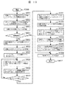
ミラーの状態取得の手順を、図10のフローチャートを用いて説明する。図10もボリューム仮想化プログラム1309の一部である。ステップ10001〜10006までは図7のステップ7001〜7005と同様である。ステップ10008〜10010で、各ディスクボリュームのミラーペアの状態を取得する。次に、これらの状態から仮想ボリュームのミラーペアの状態を作成する(ステップ10011)。例えば、ディスクボリュームのミラーペアの状態が初期化前の「無効」、初期化処理中である「初期化」、初期化が完了し主副が同じデータを持つ「同期」、ミラーを中断している「中断」、中断から再び同期状態に戻す処理中である「再同期」、障害が起きている「エラー」の6つの状態であるとすると、仮想ボリュームのミラーペアの状態は図11のように作成することができる。全てのディスクボリュームのミラーペアが一致した場合は、仮想ボリュームのミラーペアの状態もその状態になる。もし一致しない状態があれば、ディスクボリュームのミラーペアの状態の整合性が取れていないため、仮想ボリュームのミラーペアの状態は「エラー」となる。ただし、初期化処理および再同期処理では、全てのディスクボリュームのミラーペアが同時に処理を終えるとは限らないため、早く処理が終わったミラーペアの状態は「同期」となる可能性がある。その場合は不一致があっても仮想ボリュームのミラーペアの状態をエラーではなく、それぞれ「初期化」および「再同期」とする。
【0042】
仮想ボリュームのミラーペアの状態を作成したら、仮想ボリューム管理表の「処理中」の記録を削除し(ステップ10012)、ホストコンピュータにステータスを返す(ステップ10013)。このステータスとはSCSIプロトコルの一部として規格で定義されたもので、通常エラーがなければGood(バイトコード=00000)が返される。これにより、ホストコンピュータの仮想ボリューム機能制御プログラムは状態取得処理の完了を認識し、状態を読み出すために共通インタフェースにReadコマンドを送る。バーチャライゼーションサーバのボリューム仮想化プログラムは、ステップ10011で作成した仮想ボリュームのミラーペアの状態をReadコマンドに対するデータとして返送し(ステップ10015)、最後にステータスを返す(ステップ10016)。
【0043】
上述のように、図11は仮想ボリュームのミラー状態と、仮想ボリュームを構成する実際のディスクボリューム群のミラー状態の対応表である。図10のステップ10008〜10010で取得した実際のディスクボリューム群のミラー状態を図11に照らし合わせて仮想ボリュームのミラー状態を作成する(ステップ10011)。図11の対応表による変換がプロトコルの変換にあたる。
【0044】
上記の手順により、バーチャライゼーションサーバからホストコンピュータへ情報を渡す必要がある機能制御も実現することができる。
【0045】
(6) 効果
本実施形態により、異なる機能制御インタフェースを持つ複数のディスクアレイ装置が存在するストレージバーチャライゼーション環境において、仮想ボリューム単位でミラー機能などのストレージ機能を適用することができる。その際、構成する記憶領域が、どの装置に存在するかを意識することなく、共通の方法で機能制御を指示することができる。
【0046】
なお、本実施形態ではストレージバーチャライゼーションの基本機能と、機能制御の共通インタフェースが同じバーチャライゼーションサーバで提供されているが、それぞれの機能を個別の装置内で実現することも可能である。また、サーバに限らず、同様のストレージバーチャライゼーション機能を持つスイッチ装置等に適用することもできる。ここでは、これらを記憶装置の接続装置と呼ぶ。さらに、ディスクボリューム単位の制御に限らず、例えば、ディスクアレイをファイルサーバ、ファイバチャネルとSCSIプロトコルをLANとNFSプロトコル、バーチャライゼーションサーバ内の管理単位をファイルシステム、共通インタフェースをLANインタフェースとすることにより、ファイルシステム単位での機能制御にも適用することができる。
【0047】
第二の実施形態
本実施形態の構成は、図1の第一の実施形態とほぼ同様であるが、バーチャライゼーションサーバで複数の共通インタフェースを提供する。また、バーチャライゼーションサーバがディスクアレイ装置に制御を指示するときに、一部のディスクボリュームに対する指示が失敗した場合に、エラー処理を実行する手段を備える。以下、第一の実施形態と異なる点のみを説明する。
【0048】
(1) 複数の機能制御インタフェース
本実施形態では、バーチャライゼーションサーバが2つの共通インタフェースをホストコンピュータに提供する。第一の実施形態で説明した仮想ボリュームによるインタフェースに加え、図1のLANインタフェース1306を利用したLAN経由のインタフェースを提供する。共通インタフェース管理表1314は、図12の構成の表に加えて、図13の構成の表も持つ。図13の表に記録されたLANインタフェース(IPアドレス)とポート番号の組み合わせをあて先とする入力データは、機能制御ブロックとして解釈される。LANインタフェースで共通インタフェースを実現する場合、第一の実施形態でファイバチャネル上のSCSIコマンドおよびデータの送受信で実現したように、イーサネット(ゼロックス社の登録商標)上のデータ送受信で実現する。SCSIのステータスの代わりに、処理の終了を示すために確認のパケット(acknowledge)を返す。この第二の共通インタフェースを利用することにより、例えばファイルシステムを介さないところのファイバチャネルインタフェースへの入出力が不可能なホストコンピュータでは、LANインタフェースを利用した機能制御指示が可能となる。即ち、ファイバチャネルインタフェースの入出力がファイルシステム経由でのみ可能なホストコンピュータでは全ての入出力はファイル操作となるため、ユーザが入出力のアドレスやパケットのデータ構造を指定することが出来ず、共通インタフェースに制御パケットを送ることが出来ない。そのようなホストコンピュータでは、LANインタフェースを利用することで共通インタフェースに制御パケットを送ることが出来る。
【0049】
図1のホストコンピュータ1201上の仮想ボリューム機能制御プログラム1206は、LAN通信の機能を持ち、仮想ボリュームとして提供される第一の実施形態の共通インタフェースではなく、LANインタフェースを利用して実現された共通インタフェースにアクセスする機能を持つ。共通インタフェースのIPアドレスおよびポート番号は、第一の実施形態における共通インタフェースのWWNとLUNと同様に、管理者が仮想ボリューム機能制御プログラムに設定する。
【0050】
ディスクアレイ1401は、第一の実施形態で説明したLANインタフェースによる機能制御に加え、ディスクアレイ1501と同様にファイバチャネルインタフェース経由でのMode Select/Mode Senseコマンドによる機能制御方法を提供する。すなわち、バーチャライゼーションサーバ上のボリューム仮想化プログラムは、LAN経由もしくはファイバチャネル経由のどちらでもディスクアレイ1401に機能制御の指示を送ることが可能である。
【0051】
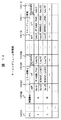
バーチャライゼーションサーバ内のボリューム管理表は、ディスクアレイ1401の複数の制御インタフェースに対応するために変更される。また、機能制御を指示したときにエラーが発生した場合の回復処理を定義するための項目が追加される。変更したディスクボリューム管理表を図14に示す。図14で14101から14106までの項目は、図3のボリューム識別子3101から装置識別子3106までの項目に対応し、変更はないので説明を省略する。14107は機能制御を指示する際に呼び出すAPIであるが、ディスクアレイ1401のように複数の制御インタフェースを持つ装置のディスクボリュームについては、それぞれのインタフェースに対応する複数のAPIを登録する。図14の例では、ディスクボリューム1を提供し、装置識別子Aで表されるディスクアレイは2つの制御インタフェースを持ち、ミラー初期化のAPIとしてそれぞれfunc1とfunc5を登録する。一方、装置識別子Bで表されるディスクアレイは制御インタフェースを1つしか持たないため、APIも1つ(func5のみ)を登録する。また、それぞれのAPIで利用する制御インタフェースを14108に記録する。
【0052】
14109のRecovery APIは、エラー処理を行う際に呼び出すAPIである。例えば、2つのディスクボリュームからなる仮想ボリュームを対象とする機能制御を指示し、一方のディスクボリュームに対する制御が成功し他方の制御が失敗した場合に、仮想ボリュームの状態を指示前の状態に戻すために、成功した方の指示を取り消すときに使用する。Recovery APIはAPIと同じ引数で呼び出され、APIと同様の方法で登録する。
(2) エラー処理
本実施形態における機能制御の指示の手順は、第一の実施形態とほぼ同様であるが、ディスクアレイが提供する複数の制御インタフェースと、あらかじめボリューム管理表に登録したRecovery APIを利用したエラー処理を行う点が異なる。以下、ミラー初期化指示の手順について第一の実施形態からの変更部分のみ説明する。ボリューム管理表のミラー初期化のRecovery APIには、ミラーの解消を指示するAPIがあらかじめ登録されているとする。
【0053】
図15は、図7のミラーの初期化処理の、ステップ7006とステップ7014の間の変更部分を示したものである。ステップ15001で制御指示を送る、ディスクボリュームのミラーペアを1つ選び、ボリューム管理表からそのディスクボリュームのミラー初期化指示に使用するAPIを1つ選ぶ(ステップ15002)。そのAPIを呼び出し(ステップ15002)、呼び出しが成功であれば全てのディスクボリュームのミラーペアについて同様の処理を繰り返す(ステップ15003、15004)。もしLANやファイバチャネルケーブルの切断などの理由でディスクアレイへの制御が指示できず、APIの呼び出しが失敗したら、別のAPIをボリューム管理表から選択し、リトライする(ステップ15005)。これはAPIが1つのディスクボリュームに対していくつかあるので、試していないAPIがあるかを判定するものである。失敗は、タイムアウトやディスクアレイからのエラーステータスの受信で認識できる。ボリューム管理表に登録されている全てのAPIで呼び出しが失敗したら、これまでにAPI呼び出しが成功したディスクボリュームのミラーペアについてRecovery APIを呼び出し、ミラーの解消を指示する(ステップ15006、15007)。このRecovery APIの呼び出しを、API呼び出しが成功した全てのディスクボリュームのミラーペアについて繰り返す(ステップ15008)。全てのAPI呼び出しが成功、もしくはエラー処理がすべて完了したら、ステップ7014以降の終了処理に進む。
【0054】
(3) 効果
本実施形態では、バーチャライゼーションサーバが複数の共通インタフェースを提供することにより、ホストコンピュータが使用する通信手段を選択することができる。そのため、各ホストコンピュータが制御指示を送るために利用できる通信手段が異なる場合にも、第一の実施形態と同様の効果が得られる。また、複数のディスクボリュームから構成される仮想ボリュームを対象とする機能を制御する場合、ディスクアレイに複数の制御指示を送り、その一部が失敗したときに、既に成功した指示を取り消し、仮想ボリュームを一貫性の取れた状態に戻すことができる。なお、本実施形態では各APIに対して単一のRecovery APIを定義したが、エラー状態毎に使用するRecovery APIを定義することもできる。言い換えれば、第三の実施形態では図14に示すように、ある1つのAPIによる処理を取り消すAPIとして1つのRecovery APIを定義している。しかし、1つのAPIに対して複数のRecovery APIを定義するような実装も考えられる。例えば、通信路障害によるエラー状態と、ストレージ装置のコントローラ障害によるエラー状態では別のRecovery APIを用いることが考えられる。このように複数のRecovery APIをエラーの種類によって使い分けることも出来る。また、本実施形態では、APIの呼び出しが成功した制御対象にはRecovery APIを使用しないが、必要に応じて、API呼び出しが成功した場合に使用するRecovery APIを定義することもできる。
【0055】
第三の実施形態
本実施形態は、本発明をファイバチャネルネットワークによるSAN環境に適用し、ディスクボリュームの機能制御に共通インタフェースを利用する例である。バーチャライゼーションサーバではなく、ファイバチャネルスイッチで共通インタフェースを提供する。さらに、機能制御のログを管理コンソールで記録し、ホストコンピュータから指示できる制御を制限するセキュリティ機能を提供する。本実施形態では、共通インタフェースとして、制御の対象となるボリュームへのMode SelectおよびMode Senseコマンドの送信により機能制御を指示する。
【0056】
(1) システムの構成
図16に本実施形態の全体構成を示す。
【0057】
ホストコンピュータ16101、16201およびディスクアレイ16401、16501の構成、動作は、第一の実施形態と同様であり、ファイバチャネルスイッチ16301に接続されている。ただし、ホストコンピュータ上の仮想ボリューム機能制御プログラムは、第一実施形態とは異なり、Read、Writeコマンドではなく、Mode Select、Mode Senseコマンドを送信する。それぞれのページコードには、あらかじめ機能制御用に定義したベンダユニークな番号を使用する。パラメータリストには、図17のような構造のデータを用いる。Mode SelectやMode Senseコマンドは、制御対象となるボリュームに送るため、制御対象をパラメータリスト内で指定する必要はない。ミラーペアの初期化のように、2つのボリュームを指定する必要がある制御では、パラメータリスト内で2つ目のボリュームを指定する。そのようなボリュームは、例えば、制御対象ボリュームに割り当てられているディスクアレイのポートのWWNとLUNをパラメータリストの一部として指定する。
【0058】
ファイバチャネルスイッチ16301について、通常のファイバチャネルスイッチと異なる点を説明する。ホストコンピュータやディスクアレイと接続するためのファイバチャネルポートを提供するポートモジュール16302は、ファイバチャネルインタフェース16310とインタフェース制御プロセッサ16311から構成される。インタフェース制御プロセッサ16311は、共通インタフェースへの制御指示を受け取ると、CPU16307に通知する。具体的には、ファイバチャネルインタフェースで受信されたSCSIコマンドのCDB(Command Descriptor Block)を解釈し、受信したコマンドが機能制御用として定義されたページコードを持つMode Select、Mode Senseコマンドであれば、共通インタフェースへのアクセスであると判断して、送信元ホストコンピュータのWWNと、送信先ボリュームのWWNおよびLUN、コマンドの内容をCPU16307に通知する。
【0059】
CPU16307はメモリ16308内のスイッチ制御プログラム16312を実行し、スイッチの動作を制御する。インタフェース対応表16313、ボリューム制御プログラムライブラリ16314、ボリューム管理表16315は第一の実施形態と同様の構成である。これらを用いてスイッチ制御プログラム16312がプロトコル変換を行う。詳細は第一、第二の実施形態と同じであるため省略する。本実施形態では、ストレージバーチャライゼーション機能はないため、仮想ボリューム管理表は持たない。また、制御対象となるディスクボリューム自体がホストコンピュータからの制御コマンドのあて先、すなわち共通インタフェースとなるため、共通インタフェース管理表も持たない。
【0060】
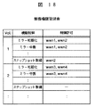
制御権限管理表16316は、図18のように構成され、各ディスクボリュームを対象とする機能制御について、制御を指示することのできるホストコンピュータをファイバチャネルインタフェースのWWNで指定する。図18の例では、ディスクボリューム1に対するミラー初期化および中断の制御は、wwn1およびwwn2のWWNを持つホストコンピュータが指示することができる。また、スナップショットの取得については、wwn2のホストコンピュータのみ指示できることを表している。これらの情報は、管理者が登録・変更する。
【0061】
スイッチ制御プログラム16312は、共通インタフェースを介した制御指示を受け取ると、LANインタフェース16309から、あらかじめ管理者により設定されたIPアドレスとポート番号で指定される管理コンソール16601に制御記録を通知する。通知内容には、時刻、制御の指示元、制御の許可および不許可、制御対象、制御内容、ディスクアレイへの指示に用いられたインタフェース、および制御の成功/失敗を識別する情報が含まれる。
【0062】
管理コンソール16601では、制御記録を蓄積するためのログ記録プログラム16605がCPU16602により実行されている。ログ記録プログラムは、ファイバチャネルスイッチからの制御記録がLANインタフェース16603に到着するのを待ち、それをログファイル16606に記録する。また、ログ記録プログラムは、管理者が記録された情報を閲覧するために、ログを表示する機能を持つ。
【0063】
(2) 共通インタフェースへの制御指示の制限とログの記録
本実施形態において、Mode Selectコマンドによりディスクボリュームの機能制御を指示するスイッチ制御プログラム16312の処理の流れを図19のフローチャートを用いて説明する。
【0064】
まず、ホストコンピュータ上の仮想ボリューム制御プログラムが、制御対象となるディスクボリュームにMode Selectコマンドを送る(ステップ19001)。Mode Selectのページコードには、機能制御用としてあらかじめ割り当てたコードを用い、図17に示す制御ブロックをパラメータリストとして送る。ファイバチャネルスイッチのポートモジュールは、通常はスイッチモジュールを介して他のポートモジュールにコマンドをフォワードするが、コマンドが機能制御用ページコードを持つMode Selectであることを検出すると、コマンドの内容とその送信元のWWNおよび送信先のWWNとLUNをCPUに通知する(ステップ19002)。スイッチのCPUは、ステップ19003で、機能制御が、指示の送信元に対して、許可されていることを確認する。まずディスクボリューム管理表を参照し、送信先ボリュームのWWNおよびLUNから制御対象のボリュームの識別子を求める。次に、制御権限管理表を参照し、そのボリュームを対象とする、制御ブロックで指定された制御機能が送信元のWWNに対して許可されていることを確認する。
【0065】
もし、制御を許可するWWNの一覧に、指示の送信元WWNが記録されていなければ制御が許可されていないので、LANインタフェースから管理コンソールのログ記録プログラムに指示を拒否したという記録を送信し(ステップ19004)、ステップ19010に進む。一方、制御が許可されていれば、第一の実施形態と同様に、ディスクボリューム管理表に登録されているAPIおよび制御インタフェースを用いて、ディスクアレイに対して機能制御を指示する(ステップ19006)。APIの呼び出し、すなわちディスクアレイの機能制御の成否を確認し(ステップ19007)、API呼び出しの成功あるいは失敗をそれぞれステップ19008、19009でログに記録する。最後に、指示の送信元ホストコンピュータにSCSIステータスを返して(ステップ19010)、処理を終了する。
【0066】
(3) 効果
本実施形態により、ストレージバーチャライゼーションを用いない通常のSAN環境において、共通インタフェースを用いたディスクボリュームの機能制御が可能となる。また、各ディスクボリュームの機能毎に制御を許可するホストコンピュータを指定し、制御権限を管理することができる。さらに、制御の履歴をログに記録することができる。なお、本実施形態では、制御権限をホストコンピュータ単位で管理したが、他の管理単位にも適用可能である。例えば、制御権限管理表の制御許可対象をユーザIDで管理し、ホストコンピュータからの制御指示にユーザIDを含めることにより、ユーザ単位での権限管理ができる。また、本実施形態では、ログ情報を直ちに外部の管理コンソールに送信するが、スイッチ内部の記憶領域に蓄積し、定期的に管理コンソールに送信、あるいは管理コンソールから取得することも可能である。
【0067】
以上述べたように、本発明の実施例によれば、各装置に固有のインタフェースは隠蔽され、ホストコンピュータは制御対象の装置の種類を意識することなく、共通のインタフェースを利用して機能を制御することが可能となる。これにより、制御指示を発行するプログラムの構成が簡単化される。
【0068】
複数の共通インタフェースを提供することにより、ホストコンピュータが使用する通信手段を選択することができる。そのため、制御指示を送るために利用できる通信手段が異なる装置が混在する環境にも対応することができる。また、複数のディスクボリュームを対象とする一連の機能制御を指示する場合、その一部が失敗したときのために、エラー処理の機能制御を定義できる。
【0069】
さらに、機能制御の種別および制御の対象毎に、制御を許可するコンピュータを管理することができる。また、制御の履歴をログに記録することができる。
【0070】
【発明の効果】
以上述べたように、本発明によれば、各装置に固有のインタフェースは隠蔽され、ホストコンピュータは制御対象の装置の種類を意識することなく、共通のインタフェースを利用して機能を制御することが可能となる。これにより、制御指示を発行するプログラムの構成が簡単化される。
【図面の簡単な説明】
【図1】本発明の第一実施形態の全体構成図。
【図2】本発明の第一実施形態における仮想ボリューム管理表の構成を示す図。
【図3】本発明の第一実施形態におけるディスクボリューム管理表の構成を示す図。
【図4】本発明の第一実施形態におけるインタフェース対応表の構成を示す図。
【図5】本発明の第一実施形態におけるディスクアレイの制御ブロックの構成を示す図。
【図6】本発明の第一実施形態における仮想ボリューム作成のフローチャート。
【図7】本発明の第一実施形態におけるミラーペア初期化のフローチャート。
【図8】本発明の第一実施形態における共通インタフェースの制御ブロックの構成を示す図。
【図9】本発明の第一実施形態における制御APIの引数データの構成を示す図。
【図10】本発明の第一実施形態における仮想ボリュームの情報取得のフローチャート。
【図11】本発明の第一実施形態におけるディスクボリュームと仮想ボリュームの状態の対応表。
【図12】本発明の第一実施形態における共通インタフェース管理表の構成を示す図。
【図13】本発明の第二実施形態における共通インタフェース管理表の追加部分の構成を示す図。
【図14】本発明の第二実施形態におけるボリューム管理表の構成を示す図。
【図15】本発明の第二実施形態におけるミラーペア初期化のフローチャート。
【図16】本発明の第三実施形態の全体構成図。
【図17】本発明の第三実施形態における共通インタフェースの制御ブロックの構成を示す図。
【図18】本発明の第三実施形態における制御権限管理表の構成を示す図。
【図19】本発明の第三実施形態におけるディスクボリュームの機能制御指示のフローチャート。
【符号の説明】
1101,1201 ホストコンピュータ
1301 バーチャライゼーションサーバ
1401,1501 ディスクアレイ
1106,1206 仮想ボリューム機能制御プログラム
1309 ボリューム仮想化プログラム
1310 インタフェース対応表
1311 機能制御プログラムライブラリ
1312ディスクボリューム管理表
1313 仮想ボリューム管理表
1314 共通インタフェース管理表
1404,1504 コントローラ
1405,1406,1505,1506 ディスクボリューム。[0001]
TECHNICAL FIELD OF THE INVENTION
The present invention relates to a technique for connecting a host computer to a plurality of storage devices, and more particularly to control of various functions provided to a user by a storage device such as a disk array.
[0002]
[Prior art]
In recent years, storage devices of computers represented by disk arrays have become more intelligent. For example, in a mirror function provided by a disk array device, when a host computer updates data in a storage area in the disk array device, the updated data is automatically written in another predetermined storage area. By instructing to stop the mirror, the stored data at that time can be saved and used for backup or the like. Since the writing of the update data to another area is executed by the controller in the disk array device, no load is imposed on the host computer, and high-speed input / output processing becomes possible (for example, see Patent Document 1).
[0003]
On the other hand, the number of storage devices in the system has increased, and different types of storage devices have been mixed. That is, storage devices having different protocols are mixed. Here, the function means mirroring or taking a snapshot of the storage device, and the function control means that the host computer controls the storage device to realize these functions.
[0004]
The host computer controls a function by accessing a function control interface provided by the disk array and sending an instruction to a predefined storage device using a protocol specific to the storage device. The function control interface can be realized in various forms such as an In-band SCSI command and TCP / IP communication via a LAN (for example, see Patent Document 2).
[0005]
In addition, a storage area network (SAN: Storage Area Network) that connects a plurality of host computers and storage devices via a network has been widely used. The SAN is a high-speed network dedicated to data input / output such as a fiber channel, and can improve the input / output performance of a computer. Further, various storage areas can be used, for example, a group of computers connected by a SAN can share one storage device, and conversely, one computer can access a plurality of storage devices. Recently, not only storage devices / storage areas are shared, but storage areas (disk volumes) provided by the storage apparatuses are combined or divided to provide virtual storage areas (virtual volumes) to host computers. Storage virtualization technology has also been introduced, and more flexible management of storage areas is possible.
[0006]
[Patent Document 1]
U.S. Pat. No. 5,845,295
[Patent Document 2]
U.S. Pat. No. 5,867,736
[0007]
[Problems to be solved by the invention]
In a computer system in which a plurality of different types of storage devices coexist, such as a SAN environment, when using the intelligent functions provided by the storage devices, the host computer identifies the type of disk array to be controlled and assigns each storage device It is necessary to send a function control instruction through a unique interface. Even for control of the same function, different control programs must be prepared in the host computer for each device and used separately, which complicates the control.
[0008]
In addition, in storage virtualization, it is conceivable to realize an intelligent function in units of virtual volumes using functions provided by a storage device.At this time, it is assumed that a virtual volume is configured from a plurality of disk volumes. It is necessary to instruct the control of the function for each disk volume. Therefore, the host computer needs to identify the device that provides the actual storage area of the virtual volume and use a control interface unique to each device, which complicates the control.
[0009]
SUMMARY OF THE INVENTION An object of the present invention is to provide a common control interface independent of a device type to control various functions of different types of storage devices, and to realize simplification of control.
[0010]
[Means for Solving the Problems]
The present invention provides a common interface for controlling the functions of a storage device in a virtualization server or a switch in a computer system, and provides a function control method independent of the type of the storage device. The host computer sends a function control instruction to the common interface using a predefined protocol regardless of the type of storage device to be controlled. The device that provides the common interface manages the correspondence between the storage area recognized by the host computer and the storage area provided by the storage device. The storage device further includes means for converting a protocol of the common interface into a protocol unique to each device, and means for implementing function control via an interface unique to each storage device.
[0011]
When the device that provides the common interface receives the instruction for function control, it interprets the storage area to be instructed and the storage device that provides it. For example, if the instruction is for a certain virtual volume, the disk volumes that make up the virtual volume are the targets of the instruction. The type of the storage device that provides the storage area to be instructed is identified, and the function control is instructed through a function control interface unique to the device. An interface unique to each device is hidden by the interface server, and the host computer can control functions using a common interface without being aware of the type of device to be controlled. The host computer is compatible with a plurality of interfaces, and there is no need to use each of them properly, so that control can be simplified.
[0012]
BEST MODE FOR CARRYING OUT THE INVENTION
First embodiment
This embodiment uses a mirror function of a disk array device in a storage virtualization environment in which a storage area provided by two disk array devices connected by Fiber Channel and having different function control interfaces is virtualized by a virtualization server. This is an example in which the realized mirror function of the virtual volume is controlled using a common interface provided by the virtualization server.
[0013]
(1) System configuration
FIG. 1 shows the overall configuration of the present embodiment.
[0014]
There are two
[0015]
A virtual volume
[0016]
In the
[0017]
The
[0018]
The
[0019]
(2) Description of function control of disk array device
The function control of the disk array will be described using the mirror function as an example. The mirror function is a function of duplicating data by treating one of two disk volumes as a main volume and the other as a secondary volume, and can perform five controls of initialization, suspension, resynchronization, cancellation, and status acquisition.
[0020]
For example, assuming that a
[0021]
In the
[0022]
The
[0023]
(3) Description of common interface
The common interface provided by the virtualization server can be realized by various methods in the same manner as the function control interface provided by the disk array device. However, in the present embodiment, the host computer recognizes the shared volume as a disk volume connected by a fiber channel. An example will be described in which the virtual volume is implemented as a virtual volume.
[0024]
The host computer recognizes the common interface as a readable and writable storage area like other virtual volumes, and exchanges control information by issuing Read and Write commands. However, a disk volume as an actual storage area is not allocated, and only the address space is provided by the
[0025]
When receiving the Write command for the first 512 bytes of the common interface, the
[0026]
The administrator sets the WWN and LUN of the fiber channel interface to be assigned to the common interface as parameters of the virtual volume function control program of the host computer. Alternatively, the virtual volume function control program on the host computer issues an Inquiry command to each LU connected to the Fiber Channel interface, and searches for an LU that returns a vendor ID and a product ID unique to a predefined common interface. The common interface can be specified automatically.
[0027]
To realize the common interface, the virtualization server has a virtual volume management table 1313, a disk volume management table 1312, an interface correspondence table 1310, a function
[0028]
The virtual volume management table 1313 has a configuration as shown in FIG. 2, and manages the correspondence between each virtual volume and the actual disk volume that configures it. Each virtual volume is assigned a unique serial number as an identifier (2101). Also, the WWN (World Wide Name) of the Fiber Channel port of the virtualization server and (2102) and the LUN (Logical Unit Number) of the virtual volume, which are allocated for the host computer to access the virtual volume, are recorded (2103). . Further, identifiers (serial numbers) of actual disk volumes constituting the virtual volume are recorded in 2104 to 2107 of the table. In the example of the
[0029]
The disk volumes are managed separately from the virtual volumes by a disk volume management table 1312 having a configuration as shown in FIG. Each disk volume has a unique serial number as an identifier (3101), and the WWN (3102) of the fiber channel port of the disk array device assigned to the disk volume, and the LUN (3103) and capacity (3104) of the disk volume are assigned. Be recorded. Further, the model (3105) and the device identifier of the disk array device that provides the disk volume are recorded (3106). The model information is information unique to the type of the device, such as a vendor ID and a product ID returned in response to the inquiry command. Generally, the protocol changes when the model changes. The device identifier is a unique serial number assigned to each disk array device.
[0030]
Each API is provided by the function
[0031]
Each entry in the disk volume management table in FIG. 3 is created by the virtualization server administrator when the virtualization server recognizes a new disk volume. However, some items can be automatically registered in the volume management table by the volume virtualization program without depending on the operation of the administrator. For example, it is possible to scan the LU connected to the fiber channel interface and detect its WWN and LUN, and obtain the capacity by issuing a SCSI Read Capacity command to each disk volume. For the model information, a SCSI Inquiry command is issued to the disk volume, and a vendor ID and a product ID can be acquired and recorded. In addition, each API installs the correspondence between the model information and the API to be used as an interface correspondence table 1310 as shown in FIG. 4 in advance, so that the necessary API is recorded in the disk volume management table according to the device identifier. be able to.
[0032]
(4) Mirror initialization using common interface
An example in which the function of the disk array device is controlled using the common interface will be described with reference to an example of mirror initialization of a virtual volume.
[0033]
Before describing the function control using the common interface, as a pre-stage, a procedure for creating a virtual volume in the present embodiment will be described with reference to the flowchart in FIG. 6 which is a part of the
[0034]
In FIG. 1, when the
[0035]
First, in
[0036]
Here, referring to the virtual volume management table, it is checked whether or not the target virtual volume is processing another function control (step 7012). If another process is already underway, the process proceeds to step 7010. If it is not being processed, “under processing” is recorded in the control processing item of the virtual volume management table (step 7013). Further, referring to the virtual volume management table, the disk volumes constituting each virtual volume are specified (step 7004). In the example of the virtual volume management table shown in FIG. 2, it can be seen that
[0037]
Next, in
[0038]
After confirming that the mirrors can be assembled, a mirror initialization instruction is sent to the disk array device for all combinations. For each pair, control data having the structure shown in FIG. 9 to be an argument when calling the control API is created (step 7007). From the disk volume management table, an API and an interface used for a control instruction for each disk volume are checked, and the API is called using the control data and the interface as arguments (step 7008). For example, for the pair of the
[0039]
As described above, the control block received from the host computer through the common interface in
[0040]
(5) Mirror status acquisition using common interface
When acquiring the mirror status of a virtual volume, the host computer sends an instruction to the common interface in the same procedure as the above-mentioned initialization of the mirror, and the virtualization server acquires the mirror status from the disk array device. Is called. However, in the case of status acquisition, the difference is that the virtualization server needs to convert the status of the mirror of the disk volume acquired from each disk array device into the status of the mirror of the virtual volume, and transmit it to the host computer.
[0041]
The procedure for acquiring the state of the mirror will be described with reference to the flowchart of FIG. FIG. 10 is also a part of the
[0042]
After the status of the mirror pair of the virtual volume is created, the record of “in process” in the virtual volume management table is deleted (step 10012), and the status is returned to the host computer (step 10013). This status is defined by the standard as a part of the SCSI protocol, and if there is no error, Good (byte code = 00000) is returned. As a result, the virtual volume function control program of the host computer recognizes the completion of the status acquisition processing and sends a Read command to the common interface to read the status. The volume virtualization program of the virtualization server returns the status of the mirror pair of the virtual volume created in
[0043]
As described above, FIG. 11 is a correspondence table of the mirror state of the virtual volume and the mirror state of the actual disk volume group constituting the virtual volume. The mirror state of the virtual volume is created by comparing the mirror state of the actual disk volume group acquired in
[0044]
According to the above procedure, it is also possible to realize a function control that requires information to be passed from the virtualization server to the host computer.
[0045]
(6) Effect
According to the present embodiment, in a storage virtualization environment in which a plurality of disk array devices having different function control interfaces exist, a storage function such as a mirror function can be applied for each virtual volume. At this time, the function control can be instructed by a common method without being aware of which device has the storage area to be configured.
[0046]
In the present embodiment, the basic function of storage virtualization and the common interface for function control are provided by the same virtualization server. However, it is also possible to realize each function in an individual device. Further, the present invention is not limited to a server, and can be applied to a switch device having a similar storage virtualization function. Here, these are called storage device connection devices. Further, the control is not limited to disk volume units. For example, a disk array may be a file server, a Fiber Channel and SCSI protocol may be a LAN and NFS protocol, a management unit in a virtualization server may be a file system, and a common interface may be a LAN interface. Also, the present invention can be applied to function control on a file system basis.
[0047]
Second embodiment
The configuration of this embodiment is almost the same as that of the first embodiment of FIG. 1, but a plurality of common interfaces are provided by a virtualization server. Further, the virtualization server includes means for executing error processing when an instruction for some disk volumes fails when the virtualization server instructs the disk array device to perform control. Hereinafter, only different points from the first embodiment will be described.
[0048]
(1) Multiple function control interfaces
In this embodiment, the virtualization server provides two common interfaces to the host computer. An interface via a LAN using the
[0049]
The virtual volume function control program 1206 on the
[0050]
The
[0051]
The volume management table in the virtualization server is changed to support a plurality of control interfaces of the
[0052]
The
(2) Error handling
The procedure of the function control instruction according to the present embodiment is almost the same as that of the first embodiment, except that a plurality of control interfaces provided by the disk array and error processing using the Recovery API registered in the volume management table in advance are performed. What they do is different. Hereinafter, the procedure of the mirror initialization instruction will be described with respect to only the changed part from the first embodiment. It is assumed that an API instructing mirror cancellation is registered in advance in the Recovery API for mirror initialization in the volume management table.
[0053]
FIG. 15 shows a changed portion between the
[0054]
(3) Effect
In the present embodiment, the virtualization server provides a plurality of common interfaces, so that the communication means used by the host computer can be selected. Therefore, the same effects as in the first embodiment can be obtained even when the communication means that can be used by each host computer to send a control instruction is different. Also, when controlling a function that targets a virtual volume composed of a plurality of disk volumes, a plurality of control instructions are sent to the disk array, and when some of them fail, the already successful instruction is canceled and the virtual volume is canceled. Can be returned to a consistent state. In this embodiment, a single Recovery API is defined for each API. However, a Recovery API to be used for each error state can be defined. In other words, in the third embodiment, as shown in FIG. 14, one Recovery API is defined as an API for canceling processing by one certain API. However, an implementation that defines a plurality of Recovery APIs for one API is also conceivable. For example, it is conceivable to use different Recovery APIs for an error state due to a communication path failure and an error state due to a controller failure of a storage device. In this way, a plurality of Recovery APIs can be properly used depending on the type of error. Further, in the present embodiment, the Recovery API is not used for the control target for which the API call has succeeded, but a Recovery API to be used when the API call has succeeded can be defined as necessary.
[0055]
Third embodiment
This embodiment is an example in which the present invention is applied to a SAN environment using a fiber channel network, and a common interface is used for function control of a disk volume. A common interface is provided by a Fiber Channel switch instead of a virtualization server. Further, a security function is provided in which a log of function control is recorded on the management console, and control which can be instructed from the host computer is restricted. In the present embodiment, as a common interface, function control is instructed by transmitting a Mode Select and a Mode Sense command to the volume to be controlled.
[0056]
(1) System configuration
FIG. 16 shows the overall configuration of the present embodiment.
[0057]
The configurations and operations of the
[0058]
A description will be given of a
[0059]
The
[0060]
The control authority management table 16316 is configured as shown in FIG. 18, and specifies the host computer capable of instructing the control of the function control for each disk volume by the WWN of the fiber channel interface. In the example of FIG. 18, control of mirror initialization and suspension for the
[0061]
When receiving the control instruction via the common interface, the switch control program 16312 notifies the control record from the
[0062]
In the
[0063]
(2) Restricting control instructions to the common interface and recording logs
In the present embodiment, the flow of processing of the switch control program 16312 for instructing the function control of a disk volume by a Mode Select command will be described with reference to the flowchart of FIG.
[0064]
First, the virtual volume control program on the host computer sends a Mode Select command to the disk volume to be controlled (Step 19001). As the page code of Mode Select, a code previously allocated for function control is used, and the control block shown in FIG. 17 is transmitted as a parameter list. The port module of the fiber channel switch normally forwards a command to another port module via the switch module. However, when detecting that the command is Mode Select having a page code for function control, the contents of the command and the transmission of the command are transmitted. The original WWN and the destination WWN and LUN are notified to the CPU (step 19002). In
[0065]
If the source WWN of the instruction is not recorded in the list of WWNs to which the control is permitted, control is not permitted, and a record indicating that the instruction is rejected is transmitted from the LAN interface to the log recording program of the management console ( Step 19004) and proceed to Step 19010. On the other hand, if the control is permitted, as in the first embodiment, the function control is instructed to the disk array using the API and control interface registered in the disk volume management table (step 19006). . The call of the API, that is, the success or failure of the function control of the disk array is confirmed (step 19007), and the success or failure of the API call is recorded in logs at
[0066]
(3) Effect
According to the present embodiment, in a normal SAN environment that does not use storage virtualization, it is possible to control the function of a disk volume using a common interface. In addition, it is possible to designate a host computer to which control is permitted for each function of each disk volume and manage control authority. Further, the control history can be recorded in a log. In the present embodiment, the control authority is managed on a host computer basis, but can be applied to other management units. For example, the control permission target in the control authority management table is managed by a user ID, and by including the user ID in a control instruction from the host computer, authority management can be performed on a user basis. In this embodiment, the log information is immediately transmitted to the external management console. However, the log information can be stored in a storage area inside the switch and transmitted to the management console periodically or acquired from the management console.
[0067]
As described above, according to the embodiment of the present invention, the interface unique to each device is hidden, and the host computer controls the function using the common interface without being conscious of the type of the device to be controlled. It is possible to do. This simplifies the configuration of the program that issues the control instruction.
[0068]
By providing a plurality of common interfaces, the communication means used by the host computer can be selected. Therefore, it is possible to cope with an environment in which devices having different communication means available for sending a control instruction are mixed. Further, when a series of function control for a plurality of disk volumes is instructed, function control of error processing can be defined in case a part of the control fails.
[0069]
Further, it is possible to manage the computer that permits the control for each type of function control and for each control target. Further, the control history can be recorded in a log.
[0070]
【The invention's effect】
As described above, according to the present invention, the interface unique to each device is hidden, and the host computer can control the functions using the common interface without being conscious of the type of the device to be controlled. It becomes possible. This simplifies the configuration of the program that issues the control instruction.
[Brief description of the drawings]
FIG. 1 is an overall configuration diagram of a first embodiment of the present invention.
FIG. 2 is a diagram showing a configuration of a virtual volume management table according to the first embodiment of the present invention.
FIG. 3 is a diagram showing a configuration of a disk volume management table according to the first embodiment of the present invention.
FIG. 4 is a diagram showing a configuration of an interface correspondence table according to the first embodiment of the present invention.
FIG. 5 is a diagram showing a configuration of a control block of the disk array according to the first embodiment of the present invention.
FIG. 6 is a flowchart of virtual volume creation in the first embodiment of the present invention.
FIG. 7 is a flowchart of mirror pair initialization in the first embodiment of the present invention.
FIG. 8 is a diagram showing a configuration of a control block of a common interface according to the first embodiment of the present invention.
FIG. 9 is a diagram showing a configuration of argument data of a control API according to the first embodiment of the present invention.
FIG. 10 is a flowchart of acquiring information of a virtual volume in the first embodiment of the present invention.
FIG. 11 is a correspondence table of states of disk volumes and virtual volumes according to the first embodiment of the present invention.
FIG. 12 is a diagram showing a configuration of a common interface management table in the first embodiment of the present invention.
FIG. 13 is a diagram showing a configuration of an additional portion of a common interface management table according to the second embodiment of the present invention.
FIG. 14 is a diagram showing a configuration of a volume management table according to the second embodiment of the present invention.
FIG. 15 is a flowchart of mirror pair initialization according to the second embodiment of the present invention.
FIG. 16 is an overall configuration diagram of a third embodiment of the present invention.
FIG. 17 is a diagram showing a configuration of a control block of a common interface according to the third embodiment of the present invention.
FIG. 18 is a diagram showing a configuration of a control authority management table according to the third embodiment of the present invention.
FIG. 19 is a flowchart of a disk volume function control instruction according to the third embodiment of the present invention.
[Explanation of symbols]
1101, 1201 Host computer
1301 Virtualization server
1401, 1501 disk array
1106, 1206 Virtual volume function control program
1309 Volume virtualization program
1310 Interface Correspondence Table
1311 Function control program library
1312 disk volume management table
1313 Virtual Volume Management Table
1314 Common interface management table
1404, 1504 Controller
1405, 1406, 1505, 1506 Disk volume.
Claims (14)
前記ホストコンピュータから前記外部記憶に関する機能を制御する指示を受信する第1の手段と、
受信した指示から、制御対象となる外部記憶装置を識別する第2の手段と、
受信した指示から、外部記憶装置に指示する内容を選択する第3の手段と、
識別した制御対象および選択した指示内容に応じて、外部記憶装置に指示を送る方法を選択する第4の手段と、
選択した方法により、外部記憶装置に指示を送る第5の手段と、
を備えることを特徴とする記憶装置の接続装置。A connection device for a storage device connected to one or more host computers and one or more external storage devices via a network,
First means for receiving an instruction for controlling a function related to the external storage from the host computer;
Second means for identifying an external storage device to be controlled from the received instruction;
Third means for selecting content to be instructed to the external storage device from the received instruction,
Fourth means for selecting a method of sending an instruction to the external storage device according to the identified control target and the selected instruction content;
A fifth means for sending an instruction to the external storage device according to the selected method;
A connection device for a storage device, comprising:
前記第3の手段に応じて受信した指示から、ホストコンピュータが指定した制御対象に対応する、外部記憶装置が提供する1つ以上の記憶領域を識別する第7の手段と、
を更に備えることを特徴とする請求項1記載の記憶装置の接続装置。Sixth means for storing a correspondence relationship between a storage area recognized by the host computer and a storage area provided by an external storage device, referred to by the second means;
A seventh means for identifying one or more storage areas provided by the external storage device corresponding to the control target specified by the host computer from the instruction received according to the third means;
The storage device connection device according to claim 1, further comprising:
外部記憶装置から取得した複数の状態情報から、ホストコンピュータが指定した制御対象の状態を作成する第9の手段と、
前記ホストコンピュータに前記状態情報を送信する第10の手段と、
を更に備えることを特徴とする請求項1記載の記憶装置の接続装置。Eighth means for acquiring status information from an external storage device;
Ninth means for creating a state of a control target designated by the host computer from a plurality of pieces of state information obtained from the external storage device;
Tenth means for transmitting the status information to the host computer;
The storage device connection device according to claim 1, further comprising:
を備えることを特徴とする請求項1記載の記憶装置の接続装置。2. The storage device connection device according to claim 1, further comprising a plurality of said first units having different protocols.
外部記憶装置への指示の失敗を識別する第12の手段と、
外部記憶装置への指示が失敗した場合に、指示を送る別の手段を選択する第13の手段と、
を更に備えることを特徴とする請求項1記載の記憶装置の接続装置。Eleventh means for storing a plurality of methods for sending an instruction to an external storage device according to a control target and control contents designated by a host computer,
A twelfth means for identifying the failure of the instruction to the external storage device;
A thirteenth means for selecting another means for sending the instruction when the instruction to the external storage device fails;
The storage device connection device according to claim 1, further comprising:
外部記憶装置への指示が失敗した場合に、エラー処理が必要な制御対象を識別する第15の手段と、
エラー処理が必要であると識別した制御対象に対するエラー処理を実行する第16の手段と、
を更に備えることを特徴とする請求項5記載の記憶装置の接続装置。Fourteenth means for, when an instruction to the external storage device fails, storing error processing contents corresponding to the instruction;
A fifteenth means for identifying a control target requiring error processing when an instruction to the external storage device has failed;
Sixteenth means for performing error processing on a control target identified as requiring error processing,
The storage device connection device according to claim 5, further comprising:
受信した指示の、通信プロトコルの送信元に関する情報に基づいて、制御が許可されているか判別する第18の手段と、
受信した指示が、許可された制御か判別する第19の手段と、
を更に備えることを特徴とする請求項1記載の記憶装置の接続装置。Seventeenth means for storing, for each control target, a target for which control is permitted;
An eighteenth means for determining whether or not control is permitted, based on the information on the source of the communication protocol in the received instruction;
Nineteenth means for determining whether the received instruction is a permitted control,
The storage device connection device according to claim 1, further comprising:
を備えることを特徴とする請求項7記載の記憶装置の接続装置。A twentieth means for determining whether or not control is permitted, based on an identifier of a transmission source included in the instruction content of the received instruction;
The storage device connection device according to claim 7, comprising:
ホストコンピュータから外部記憶に関する機能を制御する指示を受信する手段と、
受信した指示から、制御対象となる外部記憶装置を識別する手段と、
受信した指示から、外部記憶装置に指示する内容を選択する手段と、
識別した制御対象および選択した指示内容に応じて、外部記憶装置に指示を送る方法を選択する手段と、
選択した手段により、外部記憶装置に指示を送る手段と、
を備えることを特徴とするネットワークスイッチ。A network switch connected to one or more host computers and one or more external storage devices,
Means for receiving an instruction for controlling functions related to external storage from the host computer,
Means for identifying an external storage device to be controlled from the received instruction;
Means for selecting content to be instructed to the external storage device from the received instruction,
Means for selecting a method of sending an instruction to the external storage device according to the identified control target and the selected instruction content;
Means for sending an instruction to the external storage device by the selected means;
A network switch comprising:
前記ホストコンピュータから共通インタフェースに対し前記記憶装置の機能の制御を指示するものであり制御機能と制御対象である仮想ボリュームの情報を含む制御ブロックを受信し、
特定の機能制御であることを判別し、
制御対象となる仮想ボリュームを特定し、
仮想ボリュームを構成するディスクボリュームを特定し、
前記記憶装置のディスクボリュームに固有な制御APIを呼び出す際に引数となるAPIを含む制御ブロックを作成し、
前記記憶装置に固有なインタフェースと前記制御ブロックから機能を制御するAPIを呼び出して機能制御を指示することを特徴とする接続制御方法。A connection control method for a connection device of a storage device connected to a storage device group including two or more storage devices having different interfaces from one or more host computers,
A control block that instructs control of the function of the storage device from the host computer to a common interface and receives a control block including information on a control function and a virtual volume to be controlled,
Determine that it is a specific function control,
Identify the virtual volume to be controlled,
Identify the disk volumes that make up the virtual volume,
Creating a control block including an API that is an argument when calling a control API specific to the disk volume of the storage device;
A connection control method, wherein a function control is instructed by calling an interface for controlling a function from the interface unique to the storage device and the control block.
前記ホストコンピュータから共通インタフェースに対し前記記憶装置の機能の制御を指示するものであり制御機能と制御対象である仮想ボリュームの情報を含む制御ブロックを受信する手段、
特定の機能制御であることを判別する手段、
制御対象となる仮想ボリュームを特定する手段、
仮想ボリュームを構成するディスクボリュームを特定する手段、
前記記憶装置のディスクボリュームに固有な制御APIを呼び出す際に引数となるAPIを含む制御ブロックを作成する手段、および
前記記憶装置に固有なインタフェースと前記制御ブロックから機能を制御するAPIを呼び出して機能制御を指示する手段、
として機能させるための接続制御プログラム。The connection device for connection control of a connection device of a storage device connected to a storage device group including two or more storage devices having different interfaces with one or more host computers,
Means for instructing control of the function of the storage device from the host computer to a common interface, and receiving a control block including information of a control function and a virtual volume to be controlled;
Means for determining that the control is a specific function control,
Means for specifying a virtual volume to be controlled,
Means for identifying the disk volumes that make up the virtual volume,
Means for creating a control block including an API as an argument when calling a control API specific to the disk volume of the storage device, and a function for calling an API for controlling a function from the interface specific to the storage device and the control block Means for instructing control,
Connection control program to function as
Priority Applications (4)
| Application Number | Priority Date | Filing Date | Title |
|---|---|---|---|
| JP2002356477A JP2004192105A (en) | 2002-12-09 | 2002-12-09 | Connection device of storage device and computer system including it |
| US10/372,913 US7020734B2 (en) | 2002-12-09 | 2003-02-26 | Connecting device of storage device and computer system including the same connecting device |
| US11/281,475 US7392336B2 (en) | 2002-12-09 | 2005-11-18 | Connecting device of storage device and computer system including the same connecting device |
| US12/118,866 US7984227B2 (en) | 2002-12-09 | 2008-05-12 | Connecting device of storage device and computer system including the same connecting device |
Applications Claiming Priority (1)
| Application Number | Priority Date | Filing Date | Title |
|---|---|---|---|
| JP2002356477A JP2004192105A (en) | 2002-12-09 | 2002-12-09 | Connection device of storage device and computer system including it |
Publications (1)
| Publication Number | Publication Date |
|---|---|
| JP2004192105A true JP2004192105A (en) | 2004-07-08 |
Family
ID=32463411
Family Applications (1)
| Application Number | Title | Priority Date | Filing Date |
|---|---|---|---|
| JP2002356477A Pending JP2004192105A (en) | 2002-12-09 | 2002-12-09 | Connection device of storage device and computer system including it |
Country Status (2)
| Country | Link |
|---|---|
| US (3) | US7020734B2 (en) |
| JP (1) | JP2004192105A (en) |
Cited By (10)
| Publication number | Priority date | Publication date | Assignee | Title |
|---|---|---|---|---|
| JP2006113826A (en) * | 2004-10-15 | 2006-04-27 | Hitachi Ltd | Controller connected to external device |
| JP2006235775A (en) * | 2005-02-23 | 2006-09-07 | Hitachi Ltd | Area set setting method and network system |
| JP2006235843A (en) * | 2005-02-23 | 2006-09-07 | Hitachi Ltd | Storage control device, and its control method |
| JP2007174068A (en) * | 2005-12-20 | 2007-07-05 | Ricoh Co Ltd | Image forming apparatus |
| JP2007305161A (en) * | 2007-08-13 | 2007-11-22 | Hitachi Ltd | Storage system and storage controller |
| JP2008176674A (en) * | 2007-01-22 | 2008-07-31 | Kyocera Mita Corp | Electronic apparatus, service provision method and program |
| JP2009271834A (en) * | 2008-05-09 | 2009-11-19 | Fujitsu Ltd | Boot control method, computer system and boot control program |
| WO2015025358A1 (en) * | 2013-08-20 | 2015-02-26 | 株式会社日立製作所 | Storage system and control method for storage system |
| JP2015169998A (en) * | 2014-03-05 | 2015-09-28 | 三菱電機インフォメーションシステムズ株式会社 | Storage control device and storage control program |
| JP2019020801A (en) * | 2017-07-12 | 2019-02-07 | 富士通株式会社 | Information processing device and management program |
Families Citing this family (63)
| Publication number | Priority date | Publication date | Assignee | Title |
|---|---|---|---|---|
| JP2004110367A (en) * | 2002-09-18 | 2004-04-08 | Hitachi Ltd | Storage system control method, storage control device, and storage system |
| US7263593B2 (en) * | 2002-11-25 | 2007-08-28 | Hitachi, Ltd. | Virtualization controller and data transfer control method |
| JP2004192105A (en) | 2002-12-09 | 2004-07-08 | Hitachi Ltd | Connection device of storage device and computer system including it |
| US7069307B1 (en) | 2002-12-20 | 2006-06-27 | Network Appliance, Inc. | System and method for inband management of a virtual disk |
| JP2004220450A (en) * | 2003-01-16 | 2004-08-05 | Hitachi Ltd | Storage device, its introduction method and its introduction program |
| US20040221123A1 (en) * | 2003-05-02 | 2004-11-04 | Lam Wai Tung | Virtual data switch and method of use |
| US6823442B1 (en) * | 2003-05-12 | 2004-11-23 | 3Pardata, Inc. | Method of managing virtual volumes in a utility storage server system |
| JP2004348464A (en) * | 2003-05-22 | 2004-12-09 | Hitachi Ltd | Storage device and communication signal shaping circuit |
| JP4060235B2 (en) * | 2003-05-22 | 2008-03-12 | 株式会社日立製作所 | Disk array device and disk array device control method |
| JP4278445B2 (en) * | 2003-06-18 | 2009-06-17 | 株式会社日立製作所 | Network system and switch |
| JP2005018193A (en) * | 2003-06-24 | 2005-01-20 | Hitachi Ltd | Interface command control method for disk device, and computer system |
| JP2005031716A (en) * | 2003-07-07 | 2005-02-03 | Hitachi Ltd | Method and device for data backup |
| JP2005071196A (en) * | 2003-08-27 | 2005-03-17 | Hitachi Ltd | Disk array apparatus and control method of its fault information |
| JP4386694B2 (en) * | 2003-09-16 | 2009-12-16 | 株式会社日立製作所 | Storage system and storage control device |
| JP4307202B2 (en) * | 2003-09-29 | 2009-08-05 | 株式会社日立製作所 | Storage system and storage control device |
| US7441052B2 (en) * | 2003-09-29 | 2008-10-21 | Hitachi Data Systems Corporation | Methods and apparatuses for providing copies of stored data for disaster recovery and other uses |
| JP4307964B2 (en) | 2003-11-26 | 2009-08-05 | 株式会社日立製作所 | Access restriction information setting method and apparatus |
| JP4156499B2 (en) * | 2003-11-28 | 2008-09-24 | 株式会社日立製作所 | Disk array device |
| JP4497918B2 (en) * | 2003-12-25 | 2010-07-07 | 株式会社日立製作所 | Storage system |
| JP4333370B2 (en) * | 2004-01-08 | 2009-09-16 | 株式会社日立製作所 | Data processing system |
| JP2005202893A (en) * | 2004-01-19 | 2005-07-28 | Hitachi Ltd | Storage device controller, storage system, recording medium recording program, information processor, and method for controlling storage system |
| JP4634049B2 (en) | 2004-02-04 | 2011-02-16 | 株式会社日立製作所 | Error notification control in disk array system |
| JP4405277B2 (en) * | 2004-02-16 | 2010-01-27 | 株式会社日立製作所 | Disk controller |
| US7467238B2 (en) * | 2004-02-10 | 2008-12-16 | Hitachi, Ltd. | Disk controller and storage system |
| JP4441286B2 (en) * | 2004-02-10 | 2010-03-31 | 株式会社日立製作所 | Storage system |
| US7133988B2 (en) * | 2004-02-25 | 2006-11-07 | Hitachi, Ltd. | Method and apparatus for managing direct I/O to storage systems in virtualization |
| JP4391265B2 (en) | 2004-02-26 | 2009-12-24 | 株式会社日立製作所 | Storage subsystem and performance tuning method |
| US20050231846A1 (en) * | 2004-04-14 | 2005-10-20 | International Business Machines Corporation | Write-once read-many hard disk drive using a WORM pointer |
| US7546631B1 (en) * | 2004-04-30 | 2009-06-09 | Sun Microsystems, Inc. | Embedded management system for a physical device having virtual elements |
| JP2005346610A (en) * | 2004-06-07 | 2005-12-15 | Hitachi Ltd | Storage system and method for acquisition and use of snapshot |
| US7058731B2 (en) * | 2004-08-03 | 2006-06-06 | Hitachi, Ltd. | Failover and data migration using data replication |
| JP4646574B2 (en) | 2004-08-30 | 2011-03-09 | 株式会社日立製作所 | Data processing system |
| US7302537B2 (en) * | 2004-10-13 | 2007-11-27 | At&T Bls Intellectual Property, Inc. | Apparatus, systems and methods for backing-up information |
| JP2006127028A (en) | 2004-10-27 | 2006-05-18 | Hitachi Ltd | Memory system and storage controller |
| JP4806557B2 (en) | 2005-10-18 | 2011-11-02 | 株式会社日立製作所 | Storage device and computer system for managing logs |
| US8447898B2 (en) * | 2005-10-28 | 2013-05-21 | Microsoft Corporation | Task offload to a peripheral device |
| US7765365B2 (en) * | 2005-11-18 | 2010-07-27 | Lsi Corporation | Method of partioning storage in systems with both single and virtual target interfaces |
| US8087021B1 (en) * | 2005-11-29 | 2011-12-27 | Oracle America, Inc. | Automated activity processing |
| US9032164B2 (en) * | 2006-02-17 | 2015-05-12 | Emulex Corporation | Apparatus for performing storage virtualization |
| US20080126789A1 (en) * | 2006-08-28 | 2008-05-29 | Jones Carl E | Method and Apparatus for Generating an Optimal Number of Spare Devices Within a RAID Storage System Having Multiple Storage Device Technology Classes |
| US7734836B2 (en) * | 2006-10-11 | 2010-06-08 | Coatney Douglas W | Method and apparatus for dynamically qualifying mass storage devices |
| US7660978B2 (en) * | 2007-03-07 | 2010-02-09 | International Business Machines Corporation | System and method to provide device unique diagnostic support with a single generic command |
| JP4990066B2 (en) * | 2007-08-21 | 2012-08-01 | 株式会社日立製作所 | A storage system with a function to change the data storage method using a pair of logical volumes |
| US8099497B2 (en) * | 2008-02-19 | 2012-01-17 | Netapp, Inc. | Utilizing removable virtual volumes for sharing data on a storage area network |
| CA2727784C (en) * | 2008-07-28 | 2015-03-31 | Sony Corporation | Client device and associated methodology of accessing networked services |
| JP4701282B2 (en) * | 2008-11-27 | 2011-06-15 | 株式会社日立製作所 | Storage system and interface management method |
| US20120005307A1 (en) * | 2010-06-30 | 2012-01-05 | Abhik Das | Storage virtualization |
| US8832342B2 (en) * | 2011-10-28 | 2014-09-09 | Lg Cns Co., Ltd. | Traffic communication module and method of forming the same |
| US8914585B1 (en) | 2012-03-31 | 2014-12-16 | Emc Corporation | System and method for obtaining control of a logical unit number |
| US8914584B1 (en) * | 2012-03-31 | 2014-12-16 | Emc Corporation | System and method for improving cache performance upon detection of a LUN control event |
| US8874799B1 (en) | 2012-03-31 | 2014-10-28 | Emc Corporation | System and method for improving cache performance |
| US8832365B1 (en) | 2012-04-20 | 2014-09-09 | Kip Cr P1 Lp | System, method and computer program product for a self-describing tape that maintains metadata of a non-tape file system |
| US9563365B2 (en) | 2012-04-30 | 2017-02-07 | Kip Cr P1 Lp | System and method for using a memory buffer to stream data from a tape to multiple clients |
| US8977827B1 (en) | 2012-05-31 | 2015-03-10 | Kip Cr P1 Lp | System, method and computer program product for recovering stub files |
| US9141542B1 (en) * | 2012-06-22 | 2015-09-22 | Kip Cr P1 Lp | System, method and computer program product for host system LTFS auto-adaptation |
| US20140195747A1 (en) | 2013-01-08 | 2014-07-10 | Greentec-Usa, Inc. | Write Once Read Many Media Systems |
| US9195483B2 (en) | 2013-01-28 | 2015-11-24 | Dell Products L.P. | Systems and methods for mirroring virtual functions in a chassis configured to receive a plurality of modular information handling systems and a plurality of modular information handling resources |
| US9307011B2 (en) * | 2013-04-01 | 2016-04-05 | Netapp, Inc. | Synchronous mirroring of NVLog to multiple destinations (architecture level) |
| KR101491015B1 (en) * | 2013-06-07 | 2015-02-06 | 에스케이플래닛 주식회사 | System for managing cloud storages, method of managing cloud storages and apparatus for the same |
| CN103858091B (en) * | 2013-12-27 | 2017-03-29 | 华为技术有限公司 | A kind of management method and equipment of storage device |
| US9940073B1 (en) * | 2014-06-30 | 2018-04-10 | EMC IP Holding Company LLC | Method and apparatus for automated selection of a storage group for storage tiering |
| US10050935B2 (en) * | 2014-07-09 | 2018-08-14 | Shape Security, Inc. | Using individualized APIs to block automated attacks on native apps and/or purposely exposed APIs with forced user interaction |
| US11169727B1 (en) | 2017-03-10 | 2021-11-09 | Pure Storage, Inc. | Synchronous replication between storage systems with virtualized storage |
Family Cites Families (56)
| Publication number | Priority date | Publication date | Assignee | Title |
|---|---|---|---|---|
| US101257A (en) | 1870-03-29 | godwin | ||
| US4805090A (en) * | 1985-09-27 | 1989-02-14 | Unisys Corporation | Peripheral-controller for multiple disk drive modules having different protocols and operating conditions |
| US5249279A (en) * | 1989-11-03 | 1993-09-28 | Compaq Computer Corporation | Method for controlling disk array operations by receiving logical disk requests and translating the requests to multiple physical disk specific commands |
| US5333277A (en) * | 1992-01-10 | 1994-07-26 | Exportech Trading Company | Data buss interface and expansion system |
| US5357475A (en) * | 1992-10-30 | 1994-10-18 | Intel Corporation | Method for detaching sectors in a flash EEPROM memory array |
| US5659704A (en) * | 1994-12-02 | 1997-08-19 | Hewlett-Packard Company | Methods and system for reserving storage space for data migration in a redundant hierarchic data storage system by dynamically computing maximum storage space for mirror redundancy |
| US6098128A (en) * | 1995-09-18 | 2000-08-01 | Cyberstorage Systems Corporation | Universal storage management system |
| US5809285A (en) * | 1995-12-21 | 1998-09-15 | Compaq Computer Corporation | Computer system having a virtual drive array controller |
| US5867736A (en) | 1996-03-29 | 1999-02-02 | Lsi Logic Corporation | Methods for simplified integration of host based storage array control functions using read and write operations on a storage array control port |
| US5761705A (en) * | 1996-04-04 | 1998-06-02 | Symbios, Inc. | Methods and structure for maintaining cache consistency in a RAID controller having redundant caches |
| US5881311A (en) * | 1996-06-05 | 1999-03-09 | Fastor Technologies, Inc. | Data storage subsystem with block based data management |
| US5845295A (en) | 1996-08-27 | 1998-12-01 | Unisys Corporation | System for providing instantaneous access to a snapshot Op data stored on a storage medium for offline analysis |
| US5794013A (en) * | 1996-10-28 | 1998-08-11 | International Business Machines Corporation | System and method for testing computer components in development environments |
| JPH10145451A (en) | 1996-11-14 | 1998-05-29 | Nippon Telegr & Teleph Corp <Ntt> | Information request relay method and device therefor |
| US5941972A (en) * | 1997-12-31 | 1999-08-24 | Crossroads Systems, Inc. | Storage router and method for providing virtual local storage |
| US6105122A (en) * | 1998-02-06 | 2000-08-15 | Ncr Corporation | I/O protocol for highly configurable multi-node processing system |
| JP3184171B2 (en) | 1998-02-26 | 2001-07-09 | 日本電気株式会社 | DISK ARRAY DEVICE, ERROR CONTROL METHOD THEREOF, AND RECORDING MEDIUM RECORDING THE CONTROL PROGRAM |
| JP3726484B2 (en) | 1998-04-10 | 2005-12-14 | 株式会社日立製作所 | Storage subsystem |
| US6230240B1 (en) * | 1998-06-23 | 2001-05-08 | Hewlett-Packard Company | Storage management system and auto-RAID transaction manager for coherent memory map across hot plug interface |
| US6542961B1 (en) | 1998-12-22 | 2003-04-01 | Hitachi, Ltd. | Disk storage system including a switch |
| US6321298B1 (en) * | 1999-01-25 | 2001-11-20 | International Business Machines Corporation | Full cache coherency across multiple raid controllers |
| JP4294142B2 (en) * | 1999-02-02 | 2009-07-08 | 株式会社日立製作所 | Disk subsystem |
| US6553408B1 (en) | 1999-03-25 | 2003-04-22 | Dell Products L.P. | Virtual device architecture having memory for storing lists of driver modules |
| US6654830B1 (en) * | 1999-03-25 | 2003-11-25 | Dell Products L.P. | Method and system for managing data migration for a storage system |
| JP4080629B2 (en) | 1999-03-30 | 2008-04-23 | 株式会社東芝 | Access control device and computer-readable storage medium storing program |
| US6430645B1 (en) * | 1999-06-09 | 2002-08-06 | International Business Machines Corporation | Fibre channel and SCSI address mapping for multiple initiator support |
| US6636908B1 (en) | 1999-06-28 | 2003-10-21 | Sangate Systems, Inc. | I/O system supporting extended functions and method therefor |
| US6877044B2 (en) * | 2000-02-10 | 2005-04-05 | Vicom Systems, Inc. | Distributed storage management platform architecture |
| US6834324B1 (en) * | 2000-04-10 | 2004-12-21 | Storage Technology Corporation | System and method for virtual tape volumes |
| JP2001325207A (en) | 2000-05-17 | 2001-11-22 | Hitachi Ltd | Switch with built-in cache, computer system and switch control method for switch with built-in cache |
| US6862648B2 (en) * | 2000-10-30 | 2005-03-01 | Sun Microsystems, Inc. | Interface emulation for storage devices |
| US6594745B2 (en) | 2001-01-31 | 2003-07-15 | Hewlett-Packard Development Company, L.P. | Mirroring agent accessible to remote host computers, and accessing remote data-storage devices, via a communcations medium |
| JP3692946B2 (en) | 2001-02-14 | 2005-09-07 | 日本電気株式会社 | Information arrival notification system and information arrival notification method used therefor |
| US7401126B2 (en) * | 2001-03-23 | 2008-07-15 | Neteffect, Inc. | Transaction switch and network interface adapter incorporating same |
| JP4122724B2 (en) | 2001-04-17 | 2008-07-23 | 株式会社日立製作所 | Data replication method and information processing system |
| JP4087097B2 (en) | 2001-11-12 | 2008-05-14 | 株式会社日立製作所 | Data relocation method and data relocation method considering database management system information |
| US7548975B2 (en) * | 2002-01-09 | 2009-06-16 | Cisco Technology, Inc. | Methods and apparatus for implementing virtualization of storage within a storage area network through a virtual enclosure |
| US7499410B2 (en) * | 2001-12-26 | 2009-03-03 | Cisco Technology, Inc. | Fibre channel switch that enables end devices in different fabrics to communicate with one another while retaining their unique fibre channel domain—IDs |
| US7433948B2 (en) * | 2002-01-23 | 2008-10-07 | Cisco Technology, Inc. | Methods and apparatus for implementing virtualization of storage within a storage area network |
| US7007152B2 (en) | 2001-12-28 | 2006-02-28 | Storage Technology Corporation | Volume translation apparatus and method |
| US6934878B2 (en) * | 2002-03-22 | 2005-08-23 | Intel Corporation | Failure detection and failure handling in cluster controller networks |
| US6683883B1 (en) * | 2002-04-09 | 2004-01-27 | Sancastle Technologies Ltd. | ISCSI-FCP gateway |
| US6889309B1 (en) | 2002-04-15 | 2005-05-03 | Emc Corporation | Method and apparatus for implementing an enterprise virtual storage system |
| JP2003316616A (en) | 2002-04-24 | 2003-11-07 | Hitachi Ltd | Computer system |
| JP2003316522A (en) | 2002-04-26 | 2003-11-07 | Hitachi Ltd | Computer system and method for controlling the same system |
| US6973516B1 (en) * | 2002-05-20 | 2005-12-06 | Intransa, Inc. | Method and apparatus for a controller capable of supporting multiple protocols |
| US6934769B2 (en) * | 2002-07-29 | 2005-08-23 | Lsi Logic Corporation | Methods and structure for SCSI/IDE translation in a storage subsystem |
| US7263593B2 (en) * | 2002-11-25 | 2007-08-28 | Hitachi, Ltd. | Virtualization controller and data transfer control method |
| JP2004192105A (en) * | 2002-12-09 | 2004-07-08 | Hitachi Ltd | Connection device of storage device and computer system including it |
| US20040117522A1 (en) * | 2002-12-11 | 2004-06-17 | Dell Products L.P. | System and method for addressing protocol translation in a storage environment |
| JP4651913B2 (en) * | 2003-02-17 | 2011-03-16 | 株式会社日立製作所 | Storage system |
| US6965956B1 (en) * | 2003-02-28 | 2005-11-15 | 3Ware, Inc. | Disk array controller and system with automated detection and control of both ATA and SCSI disk drives |
| US7155546B2 (en) * | 2003-12-18 | 2006-12-26 | Intel Corporation | Multiple physical interfaces in a slot of a storage enclosure to support different storage interconnect architectures |
| US7363395B2 (en) * | 2003-12-31 | 2008-04-22 | Intel Corporation | Intermediate device capable of communicating using different communication protocols |
| US20060004935A1 (en) * | 2004-06-30 | 2006-01-05 | Pak-Lung Seto | Multi-protocol bridge |
| US20060036786A1 (en) * | 2004-08-13 | 2006-02-16 | Barrett Kreiner | Logical remapping of storage devices |
-
2002
- 2002-12-09 JP JP2002356477A patent/JP2004192105A/en active Pending
-
2003
- 2003-02-26 US US10/372,913 patent/US7020734B2/en not_active Expired - Fee Related
-
2005
- 2005-11-18 US US11/281,475 patent/US7392336B2/en not_active Expired - Fee Related
-
2008
- 2008-05-12 US US12/118,866 patent/US7984227B2/en not_active Expired - Fee Related
Cited By (15)
| Publication number | Priority date | Publication date | Assignee | Title |
|---|---|---|---|---|
| JP4640770B2 (en) * | 2004-10-15 | 2011-03-02 | 株式会社日立製作所 | Control device connected to external device |
| JP2006113826A (en) * | 2004-10-15 | 2006-04-27 | Hitachi Ltd | Controller connected to external device |
| JP2006235775A (en) * | 2005-02-23 | 2006-09-07 | Hitachi Ltd | Area set setting method and network system |
| JP2006235843A (en) * | 2005-02-23 | 2006-09-07 | Hitachi Ltd | Storage control device, and its control method |
| JP4555703B2 (en) * | 2005-02-23 | 2010-10-06 | 株式会社日立製作所 | Area set setting method and network system |
| JP2007174068A (en) * | 2005-12-20 | 2007-07-05 | Ricoh Co Ltd | Image forming apparatus |
| JP2008176674A (en) * | 2007-01-22 | 2008-07-31 | Kyocera Mita Corp | Electronic apparatus, service provision method and program |
| JP2007305161A (en) * | 2007-08-13 | 2007-11-22 | Hitachi Ltd | Storage system and storage controller |
| JP2009271834A (en) * | 2008-05-09 | 2009-11-19 | Fujitsu Ltd | Boot control method, computer system and boot control program |
| US8788636B2 (en) | 2008-05-09 | 2014-07-22 | Fujitsu Limited | Boot controlling method of managed computer |
| WO2015025358A1 (en) * | 2013-08-20 | 2015-02-26 | 株式会社日立製作所 | Storage system and control method for storage system |
| JP5948504B2 (en) * | 2013-08-20 | 2016-07-06 | 株式会社日立製作所 | Storage system and storage system control method |
| GB2549242B (en) * | 2013-08-20 | 2020-10-28 | Hitachi Ltd | Storage system and control method for storage system |
| JP2015169998A (en) * | 2014-03-05 | 2015-09-28 | 三菱電機インフォメーションシステムズ株式会社 | Storage control device and storage control program |
| JP2019020801A (en) * | 2017-07-12 | 2019-02-07 | 富士通株式会社 | Information processing device and management program |
Also Published As
| Publication number | Publication date |
|---|---|
| US7392336B2 (en) | 2008-06-24 |
| US7984227B2 (en) | 2011-07-19 |
| US7020734B2 (en) | 2006-03-28 |
| US20060095640A1 (en) | 2006-05-04 |
| US20080222356A1 (en) | 2008-09-11 |
| US20040111485A1 (en) | 2004-06-10 |
Similar Documents
| Publication | Publication Date | Title |
|---|---|---|
| JP2004192105A (en) | Connection device of storage device and computer system including it | |
| JP4252301B2 (en) | Storage system and data backup method thereof | |
| US7313636B2 (en) | Methods and structure for supporting persistent reservations in a multiple-path storage environment | |
| US7120673B2 (en) | Computer storage system providing virtualized storage | |
| US7209986B2 (en) | Method for controlling storage system, and storage control apparatus | |
| JP4718288B2 (en) | Diskless computer operation management system | |
| US6073209A (en) | Data storage controller providing multiple hosts with access to multiple storage subsystems | |
| US7849278B2 (en) | Logical partition conversion for migration between storage units | |
| US20030236945A1 (en) | Storage virtualization in a storage area network | |
| US20090187645A1 (en) | System for providing multi-path input/output in a clustered data storage network | |
| JP2010231807A (en) | Storage device system | |
| JP2005202495A (en) | Data transfer method | |
| US20060236060A1 (en) | Assuring performance of external storage systems | |
| WO2014061054A1 (en) | Storage system and method of controlling storage system | |
| US8024534B2 (en) | Replication engine communicating with a splitter to split writes between a storage controller and replication engine | |
| JP2007048323A (en) | Virtualization controller and data migration control method | |
| JP4433372B2 (en) | Data access system and method | |
| JP5272185B2 (en) | Computer system and storage system | |
| US20090254630A1 (en) | Storage control method for managing access environment enabling host to access data | |
| JP2007141264A (en) | Storage device system | |
| JP2005322254A (en) | Computer system, computer used for this computer system, and storage device | |
| EP1589412A2 (en) | Computer data migration system | |
| JP4723532B2 (en) | Computer system, and computer and storage device used in the computer system | |
| GUENDERT et al. | BROCADE MAINFRAME CONNECTIVITY SOLUTIONS | |
| JP2007293922A (en) | Computer system, computer used for this computer system, and storage device |
Legal Events
| Date | Code | Title | Description |
|---|---|---|---|
| A621 | Written request for application examination |
Free format text: JAPANESE INTERMEDIATE CODE: A621 Effective date: 20040727 |
|
| A977 | Report on retrieval |
Free format text: JAPANESE INTERMEDIATE CODE: A971007 Effective date: 20061214 |
|
| A131 | Notification of reasons for refusal |
Free format text: JAPANESE INTERMEDIATE CODE: A131 Effective date: 20070220 |
|
| A521 | Written amendment |
Free format text: JAPANESE INTERMEDIATE CODE: A523 Effective date: 20070423 |
|
| RD02 | Notification of acceptance of power of attorney |
Free format text: JAPANESE INTERMEDIATE CODE: A7422 Effective date: 20070423 |
|
| A131 | Notification of reasons for refusal |
Free format text: JAPANESE INTERMEDIATE CODE: A131 Effective date: 20071030 |
|
| A521 | Written amendment |
Free format text: JAPANESE INTERMEDIATE CODE: A523 Effective date: 20071226 |
|
| A131 | Notification of reasons for refusal |
Free format text: JAPANESE INTERMEDIATE CODE: A131 Effective date: 20080507 |
|
| A521 | Written amendment |
Free format text: JAPANESE INTERMEDIATE CODE: A523 Effective date: 20080707 |
|
| A02 | Decision of refusal |
Free format text: JAPANESE INTERMEDIATE CODE: A02 Effective date: 20081216 |