JP2004191361A - Bending durability prediction method of electric wire and bending protective member, its device and its program - Google Patents
Bending durability prediction method of electric wire and bending protective member, its device and its program Download PDFInfo
- Publication number
- JP2004191361A JP2004191361A JP2003364519A JP2003364519A JP2004191361A JP 2004191361 A JP2004191361 A JP 2004191361A JP 2003364519 A JP2003364519 A JP 2003364519A JP 2003364519 A JP2003364519 A JP 2003364519A JP 2004191361 A JP2004191361 A JP 2004191361A
- Authority
- JP
- Japan
- Prior art keywords
- bending
- protection member
- wires
- stress
- durability
- Prior art date
- Legal status (The legal status is an assumption and is not a legal conclusion. Google has not performed a legal analysis and makes no representation as to the accuracy of the status listed.)
- Granted
Links
- 238000005452 bending Methods 0.000 title claims abstract description 408
- 238000000034 method Methods 0.000 title claims abstract description 73
- 230000001681 protective effect Effects 0.000 title description 2
- 238000004364 calculation method Methods 0.000 claims description 23
- 238000003860 storage Methods 0.000 claims description 19
- 230000008569 process Effects 0.000 claims description 5
- 238000004904 shortening Methods 0.000 abstract description 3
- 238000012545 processing Methods 0.000 description 18
- 238000010586 diagram Methods 0.000 description 15
- 238000011161 development Methods 0.000 description 9
- 230000006872 improvement Effects 0.000 description 8
- 238000004891 communication Methods 0.000 description 5
- 230000008859 change Effects 0.000 description 4
- 230000009467 reduction Effects 0.000 description 4
- 239000000463 material Substances 0.000 description 3
- 238000012360 testing method Methods 0.000 description 2
- 235000002597 Solanum melongena Nutrition 0.000 description 1
- 244000061458 Solanum melongena Species 0.000 description 1
- 210000004556 brain Anatomy 0.000 description 1
- 239000003086 colorant Substances 0.000 description 1
- 238000005094 computer simulation Methods 0.000 description 1
- 238000013461 design Methods 0.000 description 1
- 238000009826 distribution Methods 0.000 description 1
- 230000014509 gene expression Effects 0.000 description 1
- 238000003780 insertion Methods 0.000 description 1
- 230000037431 insertion Effects 0.000 description 1
- 238000009434 installation Methods 0.000 description 1
- 230000002452 interceptive effect Effects 0.000 description 1
- 238000004519 manufacturing process Methods 0.000 description 1
- 239000011159 matrix material Substances 0.000 description 1
- 230000002093 peripheral effect Effects 0.000 description 1
- 238000000611 regression analysis Methods 0.000 description 1
- 238000004088 simulation Methods 0.000 description 1
Images


Classifications
-
- G—PHYSICS
- G06—COMPUTING; CALCULATING OR COUNTING
- G06F—ELECTRIC DIGITAL DATA PROCESSING
- G06F30/00—Computer-aided design [CAD]
- G06F30/20—Design optimisation, verification or simulation
- G06F30/23—Design optimisation, verification or simulation using finite element methods [FEM] or finite difference methods [FDM]
-
- G—PHYSICS
- G06—COMPUTING; CALCULATING OR COUNTING
- G06F—ELECTRIC DIGITAL DATA PROCESSING
- G06F2111/00—Details relating to CAD techniques
- G06F2111/08—Probabilistic or stochastic CAD
-
- G—PHYSICS
- G06—COMPUTING; CALCULATING OR COUNTING
- G06F—ELECTRIC DIGITAL DATA PROCESSING
- G06F2113/00—Details relating to the application field
- G06F2113/16—Cables, cable trees or wire harnesses
-
- G—PHYSICS
- G06—COMPUTING; CALCULATING OR COUNTING
- G06F—ELECTRIC DIGITAL DATA PROCESSING
- G06F2113/00—Details relating to the application field
- G06F2113/24—Sheet material
Landscapes
- Engineering & Computer Science (AREA)
- Physics & Mathematics (AREA)
- Theoretical Computer Science (AREA)
- Computer Hardware Design (AREA)
- Evolutionary Computation (AREA)
- Geometry (AREA)
- General Engineering & Computer Science (AREA)
- General Physics & Mathematics (AREA)
- Investigating Strength Of Materials By Application Of Mechanical Stress (AREA)
- Testing Resistance To Weather, Investigating Materials By Mechanical Methods (AREA)
- A Measuring Device Byusing Mechanical Method (AREA)
Abstract
Description
本発明は、所定の屈曲部に配策される複数の電線、及びこの屈曲部に取り付けられて複数の電線を保護する屈曲保護部材の屈曲耐久性を予測する方法、その装置、並びにそのプログラムに関する。 The present invention relates to a method for predicting the bending durability of a plurality of electric wires routed at a predetermined bent portion, a bending protection member attached to the bent portion and protecting the plurality of electric wires, a device therefor, and a program therefor. .
自動車等に用いられる電線は、例えば、自動車のドアの開閉部やスライドシートのスライド部等のように屈曲を受ける部位に配設される場合がある。例えば、ドア及びボディ内の電装部品を電気的に接続する複数の電線は、ドアとボディとのひんじ部に固定されるグロメットとよばれる屈曲保護部材内を貫通して、ドアとボディとの間に架け渡される。 Electric wires used in automobiles and the like may be provided in a portion that is bent, such as an opening and closing portion of a door of an automobile or a sliding portion of a slide sheet. For example, a plurality of electric wires that electrically connect electrical components in the door and the body penetrate through a bending protection member called a grommet fixed to the fork of the door and the body, and connect the door and the body. It is spanned between.
このようなグロメット及び複数の電線は、自動車のドアの開閉やスライドシートのスライド等により、繰り返し屈曲変形を受けるため、これらの屈曲耐久性又は屈曲寿命を予測することが重要となる。従来、このようなグロメットや電線の屈曲耐久性の予測は、設計、試作及び実際の屈曲試験を繰り返すことにより行われていた。その一方で、自動車の開発期間は、ますます短縮化される傾向にあると共に予測精度の向上も求められている。そこで、例えば、下記特許文献1のように、試作レスを目指し、コンピュータによるシミュレーションにより、屈曲耐久性を予測する手法が提案されている。
上記特許文献1の屈曲耐久性予測方法では、グロメット内を挿通する複数の電線を1本の電線束とみなしてモデル化し、このモデルに基づいて、電線束の寿命を予測するようにしている。しかしながら、通常、グロメット内を挿通する電線は、複数種及び複数本存在するため、この特許文献1の方法では、どの電線のどの位置が、最初に破損するのかを正確に把握することが困難であった。また、現実的に、屈曲部では、複数の電線及びグロメットが必ず組み合わされて使用されるにも拘わらず、特許文献1の方法では、電線束のみの寿命予測を行うようにしているため、個々の電線やグロメットの寿命予測を含めた総合的な寿命予測を行うためには、別途、そのための手法が必要であった。すなわち、開発期間短縮及び予測精度向上の要望に応えるためには、さらなる改善の余地があった。
In the bending durability prediction method of
よって本発明は、上述した現状に鑑み、より高精度の寿命予測や開発期間短縮の要望を満足させることのできる屈曲耐久性予測方法、その装置及びそのプログラムを提供することを課題としている。 SUMMARY OF THE INVENTION Accordingly, an object of the present invention is to provide a bending durability prediction method, a device and a program thereof, which can satisfy the demands for more accurate life prediction and development period reduction in view of the above-mentioned current situation.
上記課題を解決するためになされた請求項1記載の屈曲耐久性予測方法は、所定の屈曲部に配策される複数の電線、及び前記屈曲部に取り付けられて前記複数の電線を保護する屈曲保護部材の屈曲耐久性を、前記複数の電線及び前記屈曲保護部材にそれぞれ対応する、雰囲気温度、応力及び屈曲耐久回数の関係を示す各予測関数を参照しつつ、有限要素法を用いて予測する方法であって、前記複数の電線、前記屈曲保護部材、前記雰囲気温度、前記複数の電線及び前記屈曲保護部材の屈曲開始形状、並びに、前記複数の電線及び前記屈曲保護部材の屈曲終了形状を設定する設定工程と、前記屈曲保護部材及び前記複数の電線の各有限要素モデルを作成する有限要素モデル作成工程と、前記屈曲開始形状から前記屈曲終了形状までの間の屈曲動作にともなう前記有限要素モデルの各有限要素における各応力を計算する応力計算工程と、前記応力計算工程にて計算された前記各応力のうちから、前記複数の電線及び前記屈曲保護部材毎の最大応力をそれぞれ検索する最大応力検索工程と、前記設定工程にて設定された前記複数の電線、前記屈曲保護部材、及び前記雰囲気温度の予測関数をそれぞれ取得する予測関数取得工程と、前記予測関数取得工程にて取得された前記各予測関数を参照し、前記複数の電線及び前記屈曲保護部材毎の最大応力に対応する各屈曲耐久回数を取得し、このうちから最短屈曲耐久回数を求める屈曲耐久回数予測工程と、前記屈曲耐久回数取得工程にて求められた前記最短屈曲耐久回数を出力する出力工程と、を含むことを特徴とする。
The bending durability prediction method according to
また、上記課題を解決するためになされた請求項2記載の屈曲耐久性予測方法は、請求項1記載の屈曲耐久性予測方法において、前記最短屈曲耐久回数に対応する前記電線上又は前記屈曲保護部材上の位置を特定する特定工程を更に含み、前記出力工程では、前記特定工程にて特定された前記位置も出力される、ことを特徴とする。
Further, a bending durability prediction method according to
また、上記課題を解決するためになされた請求項3記載の屈曲耐久性予測方法は、請求項1記載の屈曲耐久性予測方法において、前記各予測関数を参照する替わりに、前記複数の電線及び前記屈曲保護部材がそれぞれ破損すると想定される最小応力を示す各応力テーブルを参照しつつ、前記複数の電線及び前記屈曲保護部材の屈曲耐久性を、有限要素法を用いて予測する方法であって、前記予測関数読出工程に替えて、前記設定工程にて設定された前記複数の電線、前記屈曲保護部材、及び前記雰囲気温度の応力テーブルをそれぞれ読み出す応力テーブル読出工程を含み、前記屈曲耐久回数取得工程に替えて、前記応力テーブル読出工程にて読み出された前記各応力テーブル、及び前記最大応力検索工程にて検索された前記複数の電線及び前記屈曲保護部材毎の最大応力を参照し、最初に破損する前記複数の電線又は前記屈曲保護部材を特定する破損部材特定工程を含み、前記出力工程では、前記最短屈曲耐久回数に替えて、最初に破損する前記複数の電線又は前記屈曲保護部材の特定情報が出力される、ことを特徴とする。
Further, a bending durability prediction method according to
また、上記課題を解決するためになされた請求項4記載の屈曲耐久性予測方法は、所定の屈曲部に配策される複数の電線、及び前記屈曲部に取り付けられて前記複数の電線を保護する屈曲保護部材の屈曲耐久性を、有限要素法を利用して予測する方法であって、前記複数の電線及び前記屈曲保護部材にそれぞれ対応する、雰囲気温度、応力、屈曲耐久回数の関係を示す各予測関数、或いは、前記複数の電線、前記屈曲保護部材がそれぞれ破損すると想定される最小応力を示す各応力テーブルの少なくともいずれかを予め格納しておき、前記複数の電線、前記屈曲保護部材、前記雰囲気温度、前記複数の電線及び前記屈曲保護部材の屈曲開始形状、並びに、前記複数の電線及び前記屈曲保護部材の屈曲終了形状を設定する設定工程と、前記屈曲保護部材及び前記複数の電線の各有限要素モデルを作成する有限要素モデル作成工程と、前記屈曲開始形状から前記屈曲終了形状までの間の屈曲動作にともなう前記有限要素モデルの各有限要素における各応力を計算する応力計算工程と、前記応力計算工程にて計算された前記各応力のうちから、前記複数の電線及び前記屈曲保護部材毎の最大応力をそれぞれ検索する最大応力検索工程と、前記設定工程にて設定された前記複数の電線、前記屈曲保護部材、及び前記雰囲気温度に対応する前記予測関数、或いは、前記応力テーブルの少なくともいずれかを読み出す読出工程と、前記読出工程にて読み出された前記予測関数を参照し、前記複数の電線及び前記屈曲保護部材毎の最大応力に対応する各屈曲耐久回数を取得し、このうちから最短屈曲耐久回数を求めるか、或いは、前記読出工程にて読み出された前記応力テーブル、及び前記最大応力検索工程にて検索された前記複数の電線及び前記屈曲保護部材毎の最大応力を参照し、最初に破損する前記複数の電線又は前記屈曲保護部材を特定した破損特定情報を求めるか、の少なくともいずれかを行う耐久性演算工程と、前記耐久性演算工程にて求められた前記最短屈曲耐久回数又は前記破損特定情報の少なくともいずれかを出力する出力工程と、を含むことを特徴とする。
Further, the bending durability prediction method according to
また、上記課題を解決するためになされた請求項5記載の屈曲耐久性予測方法は、請求項1〜4のいずれか一項に記載の屈曲耐久性予測方法において、前記予測関数として、前記複数の電線及び前記屈曲保護部材に対してそれぞれ、複数の代表的な前記雰囲気温度の下において取得された前記応力及び前記屈曲耐久回数に関するデータに基づいて、統計的に算出された母回帰関数に対する下側信頼区間を表す曲線が採用される、ことを特徴とする。
Further, a bending durability prediction method according to
また、上記課題を解決するためになされた請求項6記載の屈曲耐久性予測方法は、請求項1〜5のいずれか一項に記載の屈曲耐久性予測方法において、前記複数の電線のうちから、最も太い電線を最も屈曲内側に配置する電線配置工程、を更に含むことを特徴とする。
Further, a bending durability prediction method according to
また、上記課題を解決するためになされた請求項7記載の屈曲耐久性予測装置は、図1の基本構成図に示すように、所定の屈曲部に配策される複数の電線、及び前記屈曲部に取り付けられて前記複数の電線を保護する屈曲保護部材の屈曲耐久性を、前記複数の電線及び前記屈曲保護部材にそれぞれ対応する、雰囲気温度、応力及び屈曲耐久回数の関係を示す各予測関数を参照しつつ、有限要素法を用いて予測する装置であって、前記複数の電線及び前記屈曲保護部材にそれぞれ対応する、雰囲気温度、応力及び屈曲耐久回数の関係を示す各予測関数を格納する予測関数格納手段5Aと、前記複数の電線、前記屈曲保護部材、前記雰囲気温度、前記複数の電線及び前記屈曲保護部材の屈曲開始形状、並びに、前記複数の電線及び前記屈曲保護部材の屈曲終了形状を設定する設定手段5Bと、前記屈曲保護部材及び前記複数の電線の各有限要素モデルを作成する有限要素モデル作成手段5Cと、前記屈曲開始形状から前記屈曲終了形状までの間の屈曲動作にともなう前記有限要素モデルの各有限要素における各応力を計算する応力計算手段5Dと、前記応力計算手段5Dにて計算された前記各応力のうちから、前記複数の電線及び前記屈曲保護部材毎の最大応力をそれぞれ検索する最大応力検索手段5Eと、前記設定手段5Bにて設定された前記複数の電線、前記屈曲保護部材、及び前記雰囲気温度の予測関数をそれぞれ、前記予測関数格納手段5Aから読み出す予測関数読出手段5Gと、前記予測関数取得手段5Gにて読み出された前記各予測関数を参照し、前記複数の電線及び前記屈曲保護部材毎の最大応力に対応する各屈曲耐久回数を取得し、このうちから最短屈曲耐久回数を求める屈曲耐久回数予測手段5Hと、前記最短屈曲耐久回数に対応する前記電線上又は前記屈曲保護部材上の位置を特定する特定手段5Fと、前記最短屈曲耐久回数及び前記位置を出力する出力手段5Iと、を含むことを特徴とする。
In order to solve the above-mentioned problem, a bending durability predicting device according to
また、上記課題を解決するためになされた請求項8記載の屈曲耐久性予測プログラムは、所定の屈曲部に配策される複数の電線、及び前記屈曲部に取り付けられて前記複数の電線を保護する屈曲保護部材の屈曲耐久性を、前記複数の電線及び前記屈曲保護部材にそれぞれ対応する、雰囲気温度、応力及び屈曲耐久回数の関係を示す各予測関数を参照しつつ、有限要素法を用いて予測するために、コンピュータを、前記複数の電線及び前記屈曲保護部材にそれぞれ対応する、雰囲気温度、応力及び屈曲耐久回数の関係を示す各予測関数を格納する予測関数格納手段、前記複数の電線、前記屈曲保護部材、前記雰囲気温度、前記複数の電線及び前記屈曲保護部材の屈曲開始形状、並びに、前記複数の電線及び前記屈曲保護部材の屈曲終了形状を設定する設定手段、前記屈曲保護部材及び前記複数の電線の各有限要素モデルを作成する有限要素モデル作成手段、前記屈曲開始形状から前記屈曲終了形状までの間の屈曲動作にともなう前記有限要素モデルの各有限要素における各応力を計算する応力計算手段、前記応力計算手段にて計算された前記各応力のうちから、前記複数の電線及び前記屈曲保護部材毎の最大応力をそれぞれ検索する最大応力検索手段、前記設定手段にて設定された前記複数の電線、前記屈曲保護部材、及び前記雰囲気温度の予測関数をそれぞれ、前記予測関数格納手段から読み出す予測関数読出手段、前記予測関数取得手段にて読み出された前記各予測関数を参照し、前記複数の電線及び前記屈曲保護部材毎の最大応力に対応する各屈曲耐久回数を取得し、このうちから最短屈曲耐久回数を求める屈曲耐久回数予測手段、前記最短屈曲耐久回数を出力する出力手段、として機能させる、ことを特徴とする。
The bending durability prediction program according to
請求項1、請求項2、請求項7及び請求項8記載の発明によれば、所定の屈曲部に取り付けられる複数の電線、屈曲保護部材、及び雰囲気温度、屈曲開始形状及び屈曲終了形状が設定され、屈曲保護部材及び複数の電線の各有限要素モデルが作成される。また、屈曲開始形状から屈曲終了形状までの間の屈曲動作にともなう各有限要素における各応力が計算され、この計算された各応力のうちから複数の電線及び屈曲保護部材毎の最大応力がそれぞれ検索される。そして、必要な各予測関数、及び複数の電線及び屈曲保護部材毎の最大応力に対応する各屈曲耐久回数が取得され、これらを参照して最短屈曲耐久回数が求められて出力される。或いは、最短屈曲耐久回数に対応する位置も出力される。したがって、屈曲部における、屈曲保護部材を含めた複数の電線の総合的な屈曲耐久性予測が可能となる。或いは、対応する位置も予測可能となる。 According to the first, second, seventh, and eighth aspects of the present invention, a plurality of electric wires, a bending protection member, an ambient temperature, a bending start shape, and a bending end shape which are attached to a predetermined bending portion are set. Then, each finite element model of the bending protection member and the plurality of electric wires is created. Further, each stress in each finite element associated with the bending operation from the bending start shape to the bending end shape is calculated, and the maximum stress for each of the plurality of electric wires and the bending protection member is respectively searched from the calculated stresses. Is done. Then, the necessary prediction functions and the number of times of bending endurance corresponding to the maximum stress for each of the plurality of wires and the bending protection member are obtained, and the shortest number of times of bending endurance is obtained and output with reference to these. Alternatively, a position corresponding to the shortest bending endurance count is also output. Therefore, it is possible to predict the overall bending durability of a plurality of wires including the bending protection member at the bending portion. Alternatively, the corresponding position can also be predicted.
また、請求項3記載の発明によれば、予測関数を参照する替わりに、複数の電線及び屈曲保護部材がそれぞれ破損すると想定される最小応力を示す各応力テーブルが参照されて、最初に破損する複数の電線又は屈曲保護部材の破損特定情報が出力される。 According to the third aspect of the present invention, instead of referring to the prediction function, each of the plurality of electric wires and the bending protection member is referred to, and each of the stress tables indicating the minimum stress that is assumed to be damaged is referred to, and is broken first. Damage identification information of a plurality of electric wires or bending protection members is output.
また、請求項4記載の発明によれば、複数の電線及び屈曲保護部材にそれぞれ対応する、雰囲気温度、応力及び屈曲耐久回数の関係を示す予測関数、及び/又は、複数の電線及び屈曲保護部材がそれぞれ破損すると想定される最小応力を示す各応力テーブルが参照されて、電線及び屈曲保護部材の最短屈曲耐久回数、及び/又は、最初に破損する複数の電線又は屈曲保護部材の特定情報が出力される。 According to the fourth aspect of the present invention, a prediction function indicating the relationship between the ambient temperature, the stress, and the number of times of bending endurance, and / or the plurality of wires and the bending protection member respectively correspond to the plurality of wires and the bending protection member. Each stress table indicating the minimum stress that is assumed to be damaged is referred to, and the minimum number of times of bending endurance of the wire and the bending protection member and / or the specific information of the plurality of wires or the bending protection member to be damaged first is output. Is done.
また、請求項5記載の発明によれば、予測関数として、屈曲保護部材及び複数の電線に対してそれぞれ、複数の代表的な雰囲気温度の下において取得された応力及び屈曲耐久回数に関するデータに基づいて、統計的に算出された母回帰関数に対する下側信頼区間を表す曲線が採用されるので、統計的にもより厳しい条件下での寿命予測が行われる。勿論、予測関数について所定の統計的信頼性も維持されるうえ、この予測関数の計算処理も容易である。 According to the fifth aspect of the present invention, as the prediction function, the bending protection member and the plurality of electric wires are respectively based on the data on the stress and the number of times of bending endurance obtained under a plurality of representative atmospheric temperatures. Since the curve representing the lower confidence interval for the statistically calculated population regression function is adopted, the life expectancy under more severe conditions is statistically calculated. Of course, the predetermined statistical reliability of the prediction function is maintained, and the calculation processing of the prediction function is easy.
また、請求項6記載の発明によれば、複数の電線のうちから、最も太い電線が最も屈曲内側に配置されて、屈曲保護部材及び複数の電線の各有限要素モデルが作成される。したがって、より厳しい屈曲経路での屈曲耐久性予測が行われるようになるため、最短屈曲耐久性がより正確に予測される。 According to the sixth aspect of the present invention, the thickest wire among the plurality of wires is arranged at the innermost bend, and each finite element model of the bending protection member and the plurality of wires is created. Therefore, since bending durability prediction on a more severe bending path is performed, the shortest bending durability is more accurately predicted.
請求項1、請求項2、請求項7及び請求項8記載の発明によれば、所定の屈曲部に取り付けられる複数の電線、屈曲保護部材、及び雰囲気温度、屈曲開始形状及び屈曲終了形状が設定され、屈曲保護部材及び複数の電線の各有限要素モデルが作成される。また、屈曲開始形状から屈曲終了形状までの間の屈曲動作にともなう各有限要素における各応力が計算され、この計算された各応力のうちから複数の電線及び屈曲保護部材毎の最大応力がそれぞれ検索される。そして、必要な各予測関数、及び複数の電線及び屈曲保護部材毎の最大応力に対応する各屈曲耐久回数が取得され、これらを参照して最短屈曲耐久回数が求められて出力される。或いは、最短屈曲耐久回数に対応する位置も出力される。したがって、屈曲部における、屈曲保護部材を含めた複数の電線の総合的な屈曲耐久性予測が可能となる。或いは、対応する位置も予測可能となる。これらの結果、高精度の寿命予測や開発期間短縮の要望を満足させることができる。 According to the first, second, seventh, and eighth aspects of the present invention, a plurality of electric wires, a bending protection member, an ambient temperature, a bending start shape, and a bending end shape which are attached to a predetermined bending portion are set. Then, each finite element model of the bending protection member and the plurality of electric wires is created. Further, each stress in each finite element associated with the bending operation from the bending start shape to the bending end shape is calculated, and the maximum stress for each of the plurality of electric wires and the bending protection member is respectively searched from the calculated stresses. Is done. Then, the necessary prediction functions and the number of times of bending endurance corresponding to the maximum stress for each of the plurality of wires and the bending protection member are obtained, and the shortest number of times of bending endurance is obtained and output with reference to these. Alternatively, a position corresponding to the shortest bending endurance count is also output. Therefore, it is possible to predict the overall bending durability of a plurality of wires including the bending protection member at the bending portion. Alternatively, the corresponding position can also be predicted. As a result, it is possible to satisfy the demand for highly accurate life prediction and shortening the development period.
また、請求項3記載の発明によれば、予測関数を参照する替わりに、複数の電線及び屈曲保護部材がそれぞれ破損すると想定される最小応力を示す各応力テーブルが参照されて、最初に破損する複数の電線又は屈曲保護部材の特定情報が出力される。この結果、改善すべき部位の特定が容易になり、開発期間短縮の一助となる。 According to the third aspect of the present invention, instead of referring to the prediction function, each of the plurality of electric wires and the bending protection member is referred to, and each of the stress tables indicating the minimum stress that is assumed to be damaged is referred to, and is broken first. Specific information of a plurality of electric wires or bending protection members is output. As a result, it is easy to specify a part to be improved, which helps to shorten the development period.
また、請求項4記載の発明によれば、複数の電線及び屈曲保護部材にそれぞれ対応する、雰囲気温度、応力及び屈曲耐久回数の関係を示す予測関数、及び/又は、複数の電線及び屈曲保護部材がそれぞれ破損すると想定される最小応力を示す応力テーブルが参照されて、電線及び屈曲保護部材の最短屈曲耐久回数、及び/又は、最初に破損する複数の電線又は屈曲保護部材の破損特定情報が出力される。この結果、更に高精度の寿命予測や開発期間短縮の要望を満足させることのできる屈曲耐久性予測方法が提供される。 According to the fourth aspect of the present invention, a prediction function indicating the relationship between the ambient temperature, the stress, and the number of times of bending endurance corresponding to the plurality of electric wires and the bending protection member, and / or the plurality of electric wires and the bending protection member. With reference to the stress table indicating the minimum stress that is assumed to be damaged respectively, the minimum number of times of bending endurance of the electric wire and the bending protection member and / or the damage identification information of a plurality of wires or the bending protection member to be damaged first is output. Is done. As a result, there is provided a bending durability prediction method capable of satisfying the demand for more accurate life prediction and development period reduction.
また、請求項5記載の発明によれば、予測関数として、屈曲保護部材及び複数の電線に対してそれぞれ、複数の代表的な雰囲気温度の下において取得された応力及び屈曲耐久回数に関するデータに基づいて、統計的に算出された母回帰関数に対する下側信頼区間を表す曲線が採用されるので、統計的にもより厳しい条件下での寿命予測が行われる。勿論、予測関数について所定の統計的信頼性も維持されるうえ、この予測関数の計算処理も容易である。これらの結果、複雑な処理手順を付加することなく、よりシビアに屈曲耐久性予測が行われるようになり、より一層の品質向上や経路案改善に貢献できる。 According to the fifth aspect of the present invention, as the prediction function, the bending protection member and the plurality of electric wires are respectively based on the data on the stress and the number of times of bending endurance obtained under a plurality of representative atmospheric temperatures. Since the curve representing the lower confidence interval for the statistically calculated population regression function is adopted, the life expectancy under more severe conditions is statistically calculated. Of course, the predetermined statistical reliability of the prediction function is maintained, and the calculation processing of the prediction function is easy. As a result, the bending durability can be predicted more severely without adding a complicated processing procedure, and it is possible to further contribute to quality improvement and route plan improvement.
また、請求項6記載の発明によれば、複数の電線のうちから、最も太い電線が最も屈曲内側に配置されて、屈曲保護部材及び複数の電線の各有限要素モデルが作成される。したがって、より厳しい屈曲経路での屈曲耐久性予測が行われるようになるため、最短屈曲耐久性がより正確に予測される。この結果、より高精度の屈曲耐久性予測方法が提供される。 According to the sixth aspect of the present invention, the thickest wire among the plurality of wires is arranged at the innermost bend, and each finite element model of the bending protection member and the plurality of wires is created. Therefore, since bending durability prediction on a more severe bending path is performed, the shortest bending durability is more accurately predicted. As a result, a more accurate bending durability prediction method is provided.
以下、本発明の実施の形態を図面に基づいて説明する。図2(A)及び図2(B)はそれぞれ、ドアが閉じられたとき及びドアが開放されたときの電線及び屈曲保護部材の状態を示す図である。図2(A)に示すように、複数の電線1がその内部に貫通されたグロメット2は、車体側パネル3とドア側パネル4との間に取り付けられる。電線1は、周知のように、所定の芯線を絶縁内皮及び絶縁外皮で被覆されて構成される。グロメット2は、周知のように、筒状の可撓性材料からなり、車体側パネル3及びドア側パネル4のそれぞれの電線引出口3a及び4aにそれぞれ固定される固定部21及び22と、これら両固定部21及び22を連結する筒部23とから構成され、その内部に複数の電線が挿通される電線挿入孔24が形成されている。
Hereinafter, embodiments of the present invention will be described with reference to the drawings. FIGS. 2A and 2B are diagrams showing the state of the electric wires and the bending protection member when the door is closed and when the door is opened, respectively. As shown in FIG. 2A, a
固定部21及び22は、筒部23よりも大径であって、それぞれの外周部には環状溝21a及び21bが形成されている。これら環状溝21a及び21bにそれぞれ、電線引出口3a及び3bが嵌めこまれて、グロメット2は所定部位に取り付けられる。また、ここには図示しないが、筒部23の表面は、蛇腹状に形成されており、ドアの開閉にともなう筒部23の急激な折れ曲がりを回避するようになっている。
The fixing
図2(A)に示すように、ドアが開放されたときには、車体側パネル3とドア側パネル4とは、相互に略平行となり、筒部23も略平行に近い状態になっている。これにともなって複数の電線1も、真っ直ぐに伸ばされた状態に保持されている。一方、図2(B)に示すように、ドアが閉じられているときには、車体側パネル3とドア側パネル4とは、相互に略90度の角度をなして、筒部23は屈曲状態になる。これにともなって複数の電線1も、折れ曲がった状態に保持されている。
As shown in FIG. 2A, when the door is opened, the vehicle
このように、ドア開閉にともない、複数の電線1及びグロメット2に対して屈曲が繰り返されるうちに、電線1に断線等の破損が発生したり、グロメット2に亀裂等の破損が発生することになる。そこで、本発明では、電線1及びグロメット2の少なくともいずれかに破損が発生する最短の屈曲耐久回数、すなわち、屈曲耐久性が予測される。或いは、最初に破損が発生する電線1又はグロメット2が予測される。なお、上記グロメット2は、請求項の屈曲保護部材に対応し、上記車体側パネル3とドア側パネル4ととの間は、請求項の屈曲部に対応する。なお、グロメット2は、上記形状に限定されることはない。
As described above, while the
本発明では、上記屈曲耐久回数又は最初に破損する部材を予測するために、有限要素法を利用する。有限要素法は、周知のように、コンピュータを利用して、複雑な構造物の連続体の応力分布等を求めることを可能にするもので、解析対象となる構造体を、三角径や矩形の網目の有限要素に分割し、それぞれの有限要素に対して基礎微分方程式をたてると共に、各有限要素の解が隣接する有限要素との解との間に連続性を満足するように連立一次方程式をたて、この解を解くことにより、未知数として定義さている各有限要素における応力等を求める手法である。有限要素法については、例えば、上記非特許文献1及び非特許文献2等にも示されているので、ここでは、その説明は、省略する。
In the present invention, the finite element method is used in order to predict the number of times of bending endurance or the member to be damaged first. As is well known, the finite element method makes it possible to use a computer to determine the stress distribution and the like of a continuum of a complex structure. The mesh is divided into mesh finite elements, basic differential equations are established for each finite element, and simultaneous linear equations are set so that the solution of each finite element satisfies the continuity between the solution with the adjacent finite element. And solving this solution to obtain stress and the like at each finite element defined as an unknown. The finite element method is also described in, for example, the above-mentioned
図3(A)及び図3(B)はそれぞれ、電線及びグロメットに対する有限要素の割り当て方と応力計算点とを示す図である。本発明では、複数の電線に対しては、それぞれ3次元梁要素にモデル化し、図3(A)に示すように、梁要素の節点n1に一致するぞれぞれの断面における4点p1〜p4で応力を求める。各電線に対して、それぞれ3次元梁要素にモデル化する手法は、2002年9月25日に、本出願人にて出願された、特願2002−279502号と類似の手法が、各電線について適応可能である。また、グロメット2に対しては、図3(B)に示すように、複数の矩形の有限要素e1〜e3、…、に分割し、これら複数の有限要素における4点p1〜p4での応力をそれぞれ求めるようにする。
FIGS. 3A and 3B are diagrams showing how to assign finite elements to electric wires and grommets and stress calculation points, respectively. In the present invention, each of a plurality of electric wires is modeled as a three-dimensional beam element, and as shown in FIG. 3A, four points p1 to p1 in each cross section corresponding to a node n1 of the beam element. The stress is determined at p4. A method of modeling each electric wire into a three-dimensional beam element is a method similar to Japanese Patent Application No. 2002-279502, filed on Sep. 25, 2002, which was filed by the present applicant. Be adaptable. Further, as shown in FIG. 3B, the
次に、本発明の実施形態に係る処理手順を実現するハードウエア構成について説明する。図4は、本発明の実施形態に係るハードウエア構成を示すブロック構成図である。図5(A)及び5(B)は共に、図4の記憶装置に格納される寿命データファイルに係る図である。 Next, a hardware configuration for realizing the processing procedure according to the embodiment of the present invention will be described. FIG. 4 is a block diagram showing a hardware configuration according to the embodiment of the present invention. FIGS. 5A and 5B are diagrams relating to the life data file stored in the storage device of FIG.
図4に示すように、本発明では、マイクロコンピュータ51、入力装置52、表示装装置53、印字装置54、記憶装置55、通信インターフェース56及びリードライト装置57で基本構成される、例えば、パーソナルコンピュータが用いられる。マイクロコンピュータ51は、CPU51a(中央演算装置)、ブートプログラム等を記憶するROM51b、各種処理結果を一時的に記憶するRAM51cを含む。入力装置52は上記各値等を入力するキーボード、マウス等であり、表示装置53は処理結果を表示するLCDやCRT等であり、印字装置54は処理結果を印字するプリンタである。
As shown in FIG. 4, in the present invention, for example, a personal computer, which basically includes a
また、記憶装置55は例えばハードディスクドライブであり、通信インターフェース56は外部装置と、例えば、インターネットやLAN回線を用いてデータ通信を行うためのモデムボード等である。リードライト装置57は、CDやDVD等の記録媒体59に格納される本発明に係る屈曲耐久性予測プログラム59aを読み込んだり、結果ファイル55bを記録媒体59に書き込んだりする装置である。これらの各構成要素は、内部バス58を介して接続されている。
The
上記記憶装置55には、少なくとも、屈曲耐久性データファイル55a及び結果ファイル55bが格納される。屈曲耐久性データファイル55aは、図5(A)に示すように、各電線55a1、55a2及びグロメット55a3に対して、複数の代表的な雰囲気温度、例えば、−40℃、0℃、25℃の下において取得された応力及び屈曲耐久回数に関するデータに基づいて、統計的に算出された予測関数y1、y2及びy3の集合体である。詳しくは、グラフ中、横軸の応力は上記屈曲開始形状において、零、もしくは、所定の基準値となるようになっている。換言すれば、この横軸の応力は、屈曲開始形状を基準としてここからの応力変化量と考えてもよい。
The
この予測関数は、好ましくは、図5(B)に示すように、周知の回帰分析により求められた母回帰関数y21に対する上側信頼区間を表す曲線y22及び下側信頼区間を表す曲線y23のうちで、下側信頼区間を表す曲線y23が採用される。信頼区間は、例えば、95%とする。このような予測関数が、各電線及びグロメットにおける複数の雰囲気温度でそれぞれ予め求められている。したがって、統計的により厳しい条件下での寿命予測が行われる。勿論、予測関数について所定の統計的信頼性も維持されるうえ、この予測関数の計算処理も容易である。これらの結果、複雑な処理手順を付加することなく、よりシビアに屈曲耐久性予測が行われるようになり、より一層の品質向上や経路案改善に貢献できる。なお、母回帰関数を用いて、屈曲耐久回数を取得するようにしてもよい。 This prediction function is preferably, as shown in FIG. 5B, a curve y22 representing an upper confidence interval and a curve y23 representing a lower confidence interval for a population regression function y21 obtained by a well-known regression analysis. , A curve y23 representing the lower confidence interval is employed. The confidence interval is, for example, 95%. Such a prediction function is obtained in advance for each of the electric wires and the grommet at a plurality of ambient temperatures. Therefore, life expectancy under statistically more severe conditions is performed. Of course, the predetermined statistical reliability of the prediction function is maintained, and the calculation processing of the prediction function is easy. As a result, the bending durability can be predicted more severely without adding a complicated processing procedure, and it is possible to further contribute to quality improvement and route plan improvement. In addition, you may make it acquire a bending endurance frequency using a mother regression function.
或いは、ここでは図示しないが、屈曲耐久性データファイル55aは、上記予測関数に替えて、各電線55a1、55a2及びグロメット55a3がそれぞれ破損すると想定される最小応力を示す応力テーブルであってもよい(請求項3に対応する)。各応力テーブルもまた、複数の代表的な雰囲気温度毎に予め取得されている。 Alternatively, although not shown here, the bending durability data file 55a may be a stress table indicating the minimum stress at which each of the electric wires 55a1, 55a2 and the grommet 55a3 is assumed to be damaged, instead of the above-mentioned prediction function ( (Corresponding to claim 3). Each stress table is also acquired in advance for each of a plurality of representative ambient temperatures.
また、結果ファイル55bは、各電線及びグロメットのそれぞれの有限要素における上記4点について計算された全応力が、所定のステップ幅毎に記録されたものである。結果ファイル55bは、例えば、テキスト形式で保存されており、適宜出力することも可能である。なお、記憶装置55は、請求項の予測関数格納手段に対応する。
The result file 55b is a file in which the total stress calculated for the above four points in each finite element of each electric wire and grommet is recorded for each predetermined step width. The result file 55b is stored in a text format, for example, and can be output as appropriate. Note that the
このような構成において、マイクロコンピュータ51は、リードライト装置57にて読み込まれた屈曲耐久性予測プログラム59aを記憶装置55にインストールする。また、電源投入後、マイクロコンピュータ51は、ROM51bに記憶されるブートプログラムにしたがって起動され、インストールされている屈曲耐久性予測プログラム59aを立ちあげる。そして、マイクロコンピュータ51は、屈曲耐久性予測プログラム59aにしたがって、電線及びその屈曲部に取り付けられて電線を保護する屈曲保護部材の屈曲耐久性を予測したり、これらを表示装置53や印字装置54から出力させたり、その結果を記憶装置55に保存させたりする。屈曲耐久性予測プログラム59aは、上記基本構成を有する他のパーソナルコンピュータ等にもインストール可能であり、インストール後は、そのコンピュータを屈曲寿命予測装置(請求項7に対応)として機能させる。なお、記録媒体59に格納される屈曲耐久性予測プログラム59aは請求項8に相当する。屈曲耐久性予測プログラム59aは、記録媒体59のみならず、インターネットやLAN等の通信回線を経由して提供されたものであってもよい。
In such a configuration, the
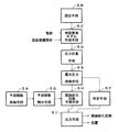
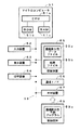
次に、図8〜図10の説明図を参照しつつ、図6及び図7のフローチャートを用いて、本発明の実施形態に係る処理手順について説明する。図6は、本発明の実施形態に係る主処理手順を示すフローチャートである。図7は、図6に示す応力計算処理手順を示すフローチャートである。図8は、本発明の実施形態に係る入力画面を示す図である。図9は、電線径と応力との関係を説明するための図である。図10は、本発明の実施形態に係る出力画面を示す図である。 Next, the processing procedure according to the embodiment of the present invention will be described with reference to the explanatory diagrams of FIGS. 8 to 10 and the flowcharts of FIGS. 6 and 7. FIG. 6 is a flowchart showing a main processing procedure according to the embodiment of the present invention. FIG. 7 is a flowchart showing the procedure of the stress calculation process shown in FIG. FIG. 8 is a diagram showing an input screen according to the embodiment of the present invention. FIG. 9 is a diagram for explaining the relationship between the wire diameter and the stress. FIG. 10 is a diagram showing an output screen according to the embodiment of the present invention.
図6に示すように、ステップS1においては、予測のための必要データが設定される。すなわち、少なくとも、屈曲動作の開始点及び終了点、電線の種類、雰囲気温度が設定される。これらを設定するために、例えば、上記表示装置53上に、図8に示すような入力画面が表示される。そして、入力装置52を用いて、この入力画面に必要な値が設定される。なお、通常、ひとつのグロメットにて保護される電線の数及び種類は複数存在するので、各電線に関しては上記入力画面を用いて繰り返し設定される。なお、入力画面は、ここに例示するものに限定されるものではない。
As shown in FIG. 6, in step S1, necessary data for prediction is set. That is, at least the starting point and the ending point of the bending operation, the type of the electric wire, and the ambient temperature are set. In order to set these, for example, an input screen as shown in FIG. 8 is displayed on the
屈曲動作の開始時点及び終了時点はそれぞれ、各電線及びグロメットの屈曲開始形状及び屈曲終了形状に対応するものである。ここには図示しないが、入力画面と共に開始時点及び終了時点に対応する各電線及びグロメットの屈曲形状をグラフィック表示させるようにしてもよい。そして、この表示を参照しつつ、開始時点及び終了時点を適宜調整することにより、正確に屈曲開始形状及び屈曲終了形状を設定することが可能である。各時点に対応する各電線及びグロメットの屈曲形状は、予め計算しておくことが可能である。 The start time and the end time of the bending operation correspond to the bending start shape and the bending end shape of each wire and grommet, respectively. Although not shown here, the bent shape of each wire and grommet corresponding to the start point and the end point may be graphically displayed together with the input screen. By appropriately adjusting the start time and the end time while referring to this display, it is possible to accurately set the bending start shape and the bending end shape. The bending shape of each wire and grommet corresponding to each time point can be calculated in advance.
なお、各電線及びグロメットの屈曲開始形状及び屈曲終了形状の設定方法は、このような設定方法に限定されず、例えば、表示装置53上に表示される各電線及びグロメットの屈曲形状を、マウス操作等により、屈曲開始形状及び屈曲終了形状にあうように、適宜設定できるようにしてもよい。屈曲開始形状から屈曲終了形状に至るまでに計算される応力は、屈曲開始形状からの応力変化量であるが、この応力変化量は、屈曲開始形状の応力を零と想定すると、応力の絶対値と等しくなるので、以降の説明では、単に、この応力変化量を応力と記載して説明する。
The method of setting the bending start shape and bending end shape of each wire and grommet is not limited to such a setting method. For example, the bending shape of each wire and grommet displayed on the
電線の種類は、文字通り、寿命予測されるべき各電線の種類である。各電線には、電線の種類に、形状特性や材料特性がリンクされて設定されている。例えば、形状特性は各電線やグロメットの長さや断面積等に関する情報であり、材料特性は2次モーメント、2次極モーメント、密度、縦弾性係数及び横弾性係数等である。これらは、予め試験等により取得しておくことが可能である。 The type of electric wire is literally the type of each electric wire whose life is to be predicted. For each electric wire, a shape characteristic and a material characteristic are linked and set to the type of the electric wire. For example, the shape characteristics are information on the length and cross-sectional area of each electric wire and grommet, and the material characteristics are a second moment, a second pole moment, a density, a modulus of longitudinal elasticity, a modulus of transverse elasticity, and the like. These can be obtained in advance by a test or the like.
雰囲気温度は、寿命予測される際の各電線及びグロメットの周囲温度であり、−40℃、0℃、25℃等の複数の代表的な値である。なお、各電線及びグロメットの取付位置に関する座標情報は、ここには図示しない、別の設定画面にて既に設定されているものとする。また、屈曲開始形状から屈曲終了形状に変形していく際の変形ステップ幅は、予めデフォルト値が設定されているものとし、このデフォルト値も、ここには図示しない、別の設定画面にて変更可能とする。このようなステップS1は、請求項の設定工程及び設定手段に対応する。 The ambient temperature is the ambient temperature of each electric wire and grommet when the life is predicted, and is a plurality of typical values such as -40C, 0C, and 25C. In addition, it is assumed that the coordinate information regarding the mounting position of each electric wire and the grommet is already set on another setting screen (not shown). In addition, it is assumed that a default value is set in advance for the deformation step width when deforming from the bending start shape to the bending end shape, and this default value is also changed on another setting screen (not shown). Make it possible. Such step S1 corresponds to a setting step and a setting unit in the claims.
次に、ステップS2においては、電線の配置が行われる。すなわち、上記設定された複数の電線うちから最も太い電線が選ばれて、この電線を最も屈曲内側に配置する。これについて、図9を用いて説明を加える。図9に示すように、真っ直ぐにのばされた電線(正確には電線被覆)1aを、矢印で示すように、屈曲半径Rにて屈曲させるものとする。 Next, in step S2, the electric wires are arranged. In other words, the thickest wire is selected from the plurality of wires set above, and this wire is arranged at the innermost bend. This will be described with reference to FIG. As shown in FIG. 9, it is assumed that a straightly stretched electric wire (more precisely, an electric wire covering) 1a is bent at a bending radius R as indicated by an arrow.
いま、電線の歪みをεとすると、
ε=ΔL/L…(1)
L=2πR2…(2)
ΔL=2πR1−2πR2…(3)
ここで、L:電線中心の長さ、ΔL:電線の伸び量、R1:電線外側の曲げ半
径、R2:電線中心の曲げ半径、を示す。
式(1)〜式(3)より、
ε=(2πR1−2πR2)/2πR2
=R1/R2−1
=(R+d)/(R+d/2)−1…(4)
と表すことができる。
ここで、R:電線の屈曲半径、d:電線径、を示す。
Now, assuming that the strain of the wire is ε,
ε = ΔL / L (1)
L = 2πR 2 (2)
ΔL = 2πR 1 -2πR 2 (3)
Here, L: the length of the center of the wire, ΔL: the amount of elongation of the wire, R 1 : the bending radius of the outside of the wire, and R 2 : the bending radius of the center of the wire.
From equations (1) to (3),
ε = (2πR 1 -2πR 2 ) / 2πR 2
= R 1 / R 2 -1
= (R + d) / (R + d / 2) -1 (4)
It can be expressed as.
Here, R: the bending radius of the electric wire, and d: the electric wire diameter.
一方、電線の応力をσとすると、
σ=Eε…(5)
と表すことができる。
On the other hand, if the stress of the electric wire is σ,
σ = Eε ... (5)
It can be expressed as.
したがって、式(4)及び式(5)から、電線径dが太い程、応力σも大きくなることがわかる。 Therefore, from Expressions (4) and (5), it is understood that the stress σ increases as the wire diameter d increases.
そこで、本発明では、できるだけ太い電線を最も屈曲内側に配置することにより、より厳しい屈曲経路を想定して、寿命予測精度を向上させる。詳しくは、グロメット内の複数の電線がL字型に屈曲される場合には、屈曲部位が一カ所であるので、最も太い電線を最も屈曲内側に配置すればよいが、グロメット内の複数の電線がZ字型に屈曲される場合には、ある屈曲点で最も屈曲内側に相当する部位が、他の屈曲点では最も屈曲外側に相当する部位になることもあるので、この点も考慮して、例えば、ワイヤーハーネス又はグロメット内の中心により細い電線を配置し、1番目及び2番目に太い電線を外側に配置することが好ましい。但し、いずれの場合にも、最も太い電線を、最も屈曲内側(複数の屈曲部がある場合にはそのうちのひとつ)に配置する。 Therefore, in the present invention, the life prediction accuracy is improved by assuming a more severe bending path by arranging the thickest possible electric wire inside the bending. Specifically, when a plurality of wires in the grommet are bent in an L-shape, since the bending portion is one, the thickest wire may be arranged at the innermost bend, but the plurality of wires in the grommet may be arranged. Is bent in a Z-shape, a portion corresponding to the innermost bend at a certain bending point may be a portion corresponding to the outermost bend at another bending point. For example, it is preferable to arrange a thinner electric wire at the center in the wire harness or grommet, and arrange the first and second thicker electric wires outside. However, in each case, the thickest electric wire is arranged on the innermost bend (if there are a plurality of bends, one of them).
このように配置することにより、より厳しい屈曲経路での屈曲耐久性予測が行われるようになるため、最短屈曲耐久性が正確に予測される。この最も太い電線の選択及び屈曲内側への配置は、ステップS1で設定された各電線の電線径を比較し、最も太い電線径を有する電線を選択し、この電線がグロメットの屈曲側の内壁に接するように、自動処理させることが可能である。或いは、入力装置52を用いて、手動で設定するようにすることも可能である。ステップS2は、請求項の電線配置工程に対応する。 By arranging in this manner, the bending durability on a more severe bending path can be predicted, so that the shortest bending durability can be accurately predicted. The selection of the thickest wire and the arrangement on the inside of the bend are performed by comparing the wire diameters of the respective wires set in step S1, selecting the wire having the largest wire diameter, and placing the wire on the inner wall on the bending side of the grommet. Automatic processing can be performed to make contact. Alternatively, it is also possible to manually set using the input device 52. Step S2 corresponds to an electric wire arranging step in the claims.
このような処理が終了すると、次に、ステップS3及びステップS4において、上記各電線及びグロメットの有限要素モデルが作成される。この有限要素モデルは、上述した通り、グロメットに対しては複数の矩形の有限要素に分割されたものとし、各電線に対してはそれぞれ3次元梁要素にモデル化されたものとする。このステップS3及びステップS4は、請求項の有限要素モデル作成工程及び有限要素モデル作成手段に対応する。 When such processing is completed, a finite element model of each electric wire and grommet is created in steps S3 and S4. This finite element model is, as described above, assumed that the grommet is divided into a plurality of rectangular finite elements, and that each electric wire is modeled as a three-dimensional beam element. Steps S3 and S4 correspond to the finite element model creation step and the finite element model creation means in the claims.
次に、ステップS5においては、各有限要素に対して、それぞれ応力が計算される。すなわち、この応力計算処理では、図7に示すように、ステップS501において、グロメットに対して、図3(A)に示すように、各有限要素における4点での応力がそれぞれ計算され、ステップS502において、各電線に対して、図3(B)に示すように、ぞれぞれの断面における4点で応力が計算される。次に、ステップS503において、これら計算された各応力を、その位置(有限要素)情報及び時点情報に関連づけて、結果ファイルに書き出し、ステップS504において、上記変形ステップ幅で規定されている分だけ、各電線及びグロメットが次の屈曲形状に変形される。このようなステップS501〜ステップS504の処理は、屈曲形状が、上記ステップS1で設定された最終形状に到達するまで繰り返され(ステップS505のN)、屈曲形状が最終形状に到達するとステップS6にもどる(ステップS505のY)。これらステップS5、ステップS501〜ステップS505は、請求項の応力計算工程及び応力計算手段に対応する。 Next, in step S5, stress is calculated for each finite element. That is, in this stress calculation process, as shown in FIG. 7, in step S501, stresses at four points in each finite element are calculated for the grommet as shown in FIG. , Stress is calculated for each electric wire at four points in each cross section, as shown in FIG. Next, in step S503, these calculated stresses are written into a result file in association with the position (finite element) information and the time point information, and in step S504, only the amount defined by the deformation step width is used. Each wire and grommet is deformed to the next bent shape. The processing in steps S501 to S504 is repeated until the bent shape reaches the final shape set in step S1 (N in step S505). When the bent shape reaches the final shape, the process returns to step S6. (Y in step S505). Step S5 and steps S501 to S505 correspond to a stress calculating step and a stress calculating unit in the claims.
次に、ステップS6においては、上記ステップS5にて計算されて結果ファイルに記録されている複数の応力のうちから、複数の電線及びグロメット毎の最大応力がそれぞれ検索される。ステップS6は請求項の最大応力検索工程に対応する。 Next, in step S6, from the plurality of stresses calculated in step S5 and recorded in the result file, the maximum stress for each of the plurality of wires and grommets is retrieved. Step S6 corresponds to the maximum stress search step in the claims.
次に、ステップS7においては、上記ステップS1にて設定された電線及びグロメットに対する予測関数が読み出される。すなわち、上述したように記憶装置55には、寿命データファイル55a格納されているので、このファイル55aから、対象となる電線又はグロメットに対応する予測関数が読み出される。この際、ステップS1にて設定された雰囲気温度に対応する予測関数が読み出されることはいうまでもない。ステップS7は、請求項の予測関数取得工程及び予測関数読出手段に対応する。
Next, in step S7, the prediction function for the electric wire and grommet set in step S1 is read. That is, as described above, since the life data file 55a is stored in the
次に、ステップS8において、上記ステップS7にて読み出された予測関数を参照しつつ、ステップS6にて検索された複数の電線及びグロメット毎の最大応力に対応する各屈曲耐久回数が取得され、更に、このうちから最短屈曲耐久回数が求められる。このように、予測関数を利用することにより、一度の屈曲動作だけで、正確に、最短屈曲耐久回数を予測することができる。ステップS8は、請求項の屈曲耐久回数予測工程及び屈曲耐久回数予測手段に対応する。 Next, in step S8, with reference to the prediction function read in step S7, the plurality of electric wires and each bending endurance number corresponding to the maximum stress for each grommet retrieved in step S6 are acquired, Further, the shortest number of times of bending endurance is determined from the above. Thus, by using the prediction function, it is possible to accurately predict the shortest number of times of bending endurance with only one bending operation. Step S8 corresponds to a bending endurance number prediction step and a bending endurance number prediction unit of the claims.
次に、ステップS9において、ステップS8にて求められた最短屈曲耐久回数に対応する電線上又はグロメット上の位置が特定される。詳しくは、最短屈曲耐久回数に対応する有限要素が特定可能なので、上記結果ファイルを参照して、対応する電線上又はグロメット上の位置も特定可能である。ステップS9は請求項の特定工程及び特定手段に対応する。 Next, in step S9, the position on the electric wire or grommet corresponding to the shortest number of times of bending obtained in step S8 is specified. Specifically, since the finite element corresponding to the shortest number of times of bending can be specified, the position on the corresponding electric wire or grommet can be specified with reference to the result file. Step S9 corresponds to the specifying step and specifying means in the claims.
次に、ステップS10において、上記最短屈曲耐久回数、及びステップS9にて特定された電線又はグロメット、並びにその位置が、表示装置53上に出力される。この出力画面は、例えば、図10に示すように、最短の屈曲耐久回数、最大応力、破損部材及び破損部位を含んで構成される。また、ここには図示しないが、出力画面と共に、破損部材及び破損部位をグラフィック表示させるようにしてもよい。更に、破損部位以外の各有限要の応力を色分け表示させるようにしてもよい。これにより、より正確に改善案を創出することが可能となる。勿論、破損部材以外を色分けされた応力と共にグラフィック表示させるようにしてもよい。ステップS10は、請求項の出力工程及び出力手段に対応する。
Next, in step S10, the shortest number of times of bending, the wire or grommet specified in step S9, and the position thereof are output on the
そして、ステップS11において結果ファイルの出力指令ありと判定されると、ステップS12において、結果ファイル55bの内容がテキスト形式で出力される。この出力は、表示装置53上にさせるようにしてもよいし、印字装置54にて紙上に印字させるようにしてもよい。また、出力すべき内容を入力装置52にて、指定できるようにしてもよい。また、この出力が不要であるときには、そのまま一連の処理を終了させるようにしてもよい(ステップS11のN)。
Then, when it is determined in step S11 that there is a result file output command, in step S12, the contents of the result file 55b are output in a text format. This output may be displayed on the
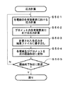
また、他の実施形態として、予測関数を参照する替わりに、上記応力テーブルを参照しつつ、複数の電線及びグロメットの屈曲耐久性を予測するようにしてもよい。この場合、上記ステップS7では、ステップS1にて設定された複数の電線、グロメット、及び雰囲気温度の応力テーブルがそれぞれ読み出される(請求項の応力テーブル読出工程に対応する)。また、上記ステップS9では、読み出された応力テーブル及び、ステップS6にて検索された電線及びグロメット毎の最大応力を参照し、最初に破損する電線又はグロメットが特定される(請求項の破損部材特定工程に対応する)。そして、ステップS10では、この最初に破損する電線又はグロメットの名称が出力される。これにより、改善すべき部位の特定が容易になり、開発期間短縮の一助となる。なお、この実施形態は、請求項3に対応する。 Further, as another embodiment, instead of referring to the prediction function, the bending durability of a plurality of wires and grommets may be predicted by referring to the stress table. In this case, in step S7, the plurality of wires, the grommet, and the stress table of the ambient temperature set in step S1 are read (corresponding to the stress table reading step in the claims). In step S9, the first broken wire or grommet is specified by referring to the read stress table and the maximum stress for each wire and grommet retrieved in step S6. Corresponding to a specific process). Then, in step S10, the name of the initially broken wire or grommet is output. This makes it easy to specify a part to be improved, which helps shorten the development period. This embodiment corresponds to claim 3.
また、更に他の実施形態として、複数の電線及びグロメットにそれぞれ対応する、雰囲気温度、応力及び屈曲耐久回数の関係を示す上記予測関数、及び/又は、複数の電線及びグロメットがそれぞれ破損すると想定される最小応力を示す上記応力テーブルを参照して、電線及びグロメットの最短屈曲耐久回数、及び/又は、最初に破損する複数の電線又は屈曲保護部材の破損特定情報を出力させるようにしてもよい。したがって、この実施形態によると、更に高精度の寿命予測や開発期間短縮の要望を満足させることのできる屈曲耐久性予測方法が提供される。なお、この実施形態は、請求項4に対応する。 Further, as still another embodiment, it is assumed that the above-described prediction function indicating the relationship between the ambient temperature, the stress, and the number of times of bending endurance respectively corresponding to the plurality of wires and the grommet, and / or the plurality of wires and the grommet are damaged. By referring to the stress table indicating the minimum stress of the wire and the grommet, the minimum number of times of bending endurance of the wire and the grommet, and / or the damage identification information of the plurality of wires or the bending protection member that breaks first may be output. Therefore, according to this embodiment, there is provided a bending durability prediction method capable of satisfying demands for more accurate life prediction and development period reduction. This embodiment corresponds to claim 4.
また、更に他の実施形態として、上述のようにしてワイヤーハーネスの耐久性を予測するときに、ワイヤーハーネスの形状データと共にボディ等に関するデータも入力しておくようにしてもよい。そうすると、最短寿命に相当する箇所の要因等を追跡しやすくなる。例えば、ワイヤーハーネスがボディと干渉しているときには、この干渉部に相当するワイヤーハーネスの一部に大きな応力が集中することが多いので、ボディ等に関するデータを入力しておくと、その部位が最短寿命となる要因がワイヤーハーネスとボディとの干渉であることを容易に突き止めることが可能となる。すなわち、ボディ等に関するデータも入力して耐久性を予測することにより、ボディ等へのワイヤーハーネスの干渉も検討することが可能となる。 Further, as still another embodiment, when estimating the durability of the wire harness as described above, data relating to the body and the like may be input together with the shape data of the wire harness. Then, it becomes easy to track factors and the like at locations corresponding to the shortest life. For example, when the wire harness is interfering with the body, large stress is often concentrated on a part of the wire harness corresponding to the interference portion. It is possible to easily find out that the cause of the life is the interference between the wire harness and the body. That is, by inputting data relating to the body and the like and predicting the durability, it is possible to examine the interference of the wire harness with the body and the like.
このように、本発明の実施形態によれば、より高精度の寿命予測や開発期間短縮の要望を満足させることのできる屈曲耐久性予測方法が提供される。また、より厳しい屈曲経路での屈曲耐久性予測が行われるため、最短屈曲耐久性が正確に予測される。更に、統計的にもより厳しい条件下での屈曲耐久性予測が行われるため、よりシビアに屈曲耐久性予測が行われるようになり、より一層の品質向上や経路案改善に貢献できる。 As described above, according to the embodiment of the present invention, there is provided a bending durability prediction method capable of satisfying a demand for more accurate life prediction and development period reduction. In addition, since bending durability prediction is performed on a more severe bending path, the shortest bending durability is accurately predicted. Furthermore, since the bending durability is statistically predicted under more severe conditions, the bending durability is more severely predicted, which contributes to further improvement of quality and improvement of a route plan.
なお、上記実施形態に本発明は限定されるものではない。例えば、屈曲部はドアのひんじ部に限定されるものではないし、本発明の適用範囲は自動車内に限定されるものでもない。また、グロメットの形状も実施形態に限定されるものではない。 The present invention is not limited to the above embodiment. For example, the bent portion is not limited to the hinge portion of the door, and the scope of the present invention is not limited to the inside of an automobile. Further, the shape of the grommet is not limited to the embodiment.
1 電線
2 グロメット
3 車体側パネル
4 ドア側パネル
51 マイクロコンピュータ
52 入力装置
53 表示装置
54 印字装置
55 記憶装置
56 通信インターフェース
57 リードライト装置
58 内部バス
59 記録媒体
DESCRIPTION OF
Claims (8)
前記複数の電線、前記屈曲保護部材、前記雰囲気温度、前記複数の電線及び前記屈曲保護部材の屈曲開始形状、並びに、前記複数の電線及び前記屈曲保護部材の屈曲終了形状を設定する設定工程と、
前記屈曲保護部材及び前記複数の電線の各有限要素モデルを作成する有限要素モデル作成工程と、
前記屈曲開始形状から前記屈曲終了形状までの間の屈曲動作にともなう前記有限要素モデルの各有限要素における各応力を計算する応力計算工程と、
前記応力計算工程にて計算された前記各応力のうちから、前記複数の電線及び前記屈曲保護部材毎の最大応力をそれぞれ検索する最大応力検索工程と、
前記設定工程にて設定された前記複数の電線、前記屈曲保護部材、及び前記雰囲気温度の予測関数をそれぞれ取得する予測関数取得工程と、
前記予測関数取得工程にて取得された前記各予測関数を参照し、前記複数の電線及び前記屈曲保護部材毎の最大応力に対応する各屈曲耐久回数を取得し、このうちから最短屈曲耐久回数を求める屈曲耐久回数予測工程と、
前記屈曲耐久回数取得工程にて求められた前記最短屈曲耐久回数を出力する出力工程と、
を含むことを特徴とする電線及び屈曲保護部材の屈曲耐久性予測方法。 A plurality of wires arranged in a predetermined bent portion, and a bending durability of a bending protection member attached to the bending portion and protecting the plurality of wires, respectively, corresponds to the plurality of wires and the bending protection member. A method of predicting using the finite element method, while referring to each prediction function showing the relationship between the ambient temperature, the stress and the number of times of bending endurance,
A setting step of setting a bending start shape of the plurality of wires, the bending protection member, the ambient temperature, the plurality of wires and the bending protection member, and a bending end shape of the plurality of wires and the bending protection member,
A finite element model creation step of creating each finite element model of the bending protection member and the plurality of electric wires,
A stress calculation step of calculating each stress in each finite element of the finite element model with the bending operation from the bending start shape to the bending end shape,
From among the stresses calculated in the stress calculation step, a maximum stress search step of searching for a maximum stress for each of the plurality of wires and the bending protection member,
The plurality of wires set in the setting step, the bending protection member, and a prediction function obtaining step of obtaining a prediction function of the ambient temperature,
With reference to the prediction functions obtained in the prediction function obtaining step, obtain the respective bending endurance times corresponding to the maximum stress for each of the plurality of wires and the bending protection member, and determine the shortest bending endurance number from among them. Required bending endurance frequency prediction process,
An output step of outputting the shortest number of times of bending endurance obtained in the bending endurance number obtaining step,
A method for predicting bending durability of an electric wire and a bending protection member, comprising:
前記最短屈曲耐久回数に対応する前記電線上又は前記屈曲保護部材上の位置を特定する特定工程を更に含み、
前記出力工程では、前記特定工程にて特定された前記位置も出力される、
ことを特徴とする電線及び屈曲保護部材の屈曲耐久性予測方法。 In the bending durability prediction method according to claim 1,
The method further includes a specifying step of specifying a position on the electric wire or the bending protection member corresponding to the shortest bending durability number,
In the output step, the position specified in the specifying step is also output,
A method for predicting the bending durability of an electric wire and a bending protection member.
前記各予測関数を参照する替わりに、前記複数の電線及び前記屈曲保護部材がそれぞれ破損すると想定される最小応力を示す各応力テーブルを参照しつつ、前記複数の電線及び前記屈曲保護部材の屈曲耐久性を、有限要素法を用いて予測する方法であって、
前記予測関数取得工程に替えて、前記設定工程にて設定された前記複数の電線、前記屈曲保護部材、及び前記雰囲気温度の応力テーブルをそれぞれ読み出す応力テーブル読出工程を含み、
前記屈曲耐久回数取得工程に替えて、前記応力テーブル読出工程にて読み出された前記各応力テーブル、及び前記最大応力検索工程にて検索された前記複数の電線及び前記屈曲保護部材毎の最大応力を参照し、最初に破損する前記複数の電線又は前記屈曲保護部材を特定する破損部材特定工程を含み、
前記出力工程では、前記最短屈曲耐久回数に替えて、最初に破損する前記複数の電線又は前記屈曲保護部材の特定情報が出力される、
ことを特徴とする電線及び屈曲保護部材の屈曲耐久性予測方法。 In the bending durability prediction method according to claim 1,
Instead of referring to each of the prediction functions, the endurance of the plurality of wires and the bending protection member is referred to while referring to each stress table indicating a minimum stress at which the plurality of wires and the bending protection member are assumed to be damaged. Is a method of predicting the property using a finite element method,
In place of the prediction function obtaining step, the plurality of wires set in the setting step, the bending protection member, and a stress table reading step of reading the stress table of the ambient temperature, respectively,
Each of the stress tables read in the stress table reading step, and the maximum stress for each of the plurality of electric wires and the bending protection member searched in the maximum stress searching step, instead of the bending endurance number obtaining step. Refer to, including a damaged member identification step of identifying the plurality of wires or the bending protection member to be broken first,
In the output step, in place of the shortest bending durability number, specific information of the plurality of wires or the bending protection member that is damaged first is output.
A method for predicting the bending durability of an electric wire and a bending protection member.
前記複数の電線及び前記屈曲保護部材にそれぞれ対応する、雰囲気温度、応力、屈曲耐久回数の関係を示す各予測関数、或いは、前記複数の電線、前記屈曲保護部材がそれぞれ破損すると想定される最小応力を示す各応力テーブルの少なくともいずれかを予め格納しておき、
前記複数の電線、前記屈曲保護部材、前記雰囲気温度、前記複数の電線及び前記屈曲保護部材の屈曲開始形状、並びに、前記複数の電線及び前記屈曲保護部材の屈曲終了形状を設定する設定工程と、
前記屈曲保護部材及び前記複数の電線の各有限要素モデルを作成する有限要素モデル作成工程と、
前記屈曲開始形状から前記屈曲終了形状までの間の屈曲動作にともなう前記有限要素モデルの各有限要素における各応力を計算する応力計算工程と、
前記応力計算工程にて計算された前記各応力のうちから、前記複数の電線及び前記屈曲保護部材毎の最大応力をそれぞれ検索する最大応力検索工程と、
前記設定工程にて設定された前記複数の電線、前記屈曲保護部材、及び前記雰囲気温度に対応する前記予測関数、或いは、前記応力テーブルの少なくともいずれかを読み出す読出工程と、
前記読出工程にて読み出された前記予測関数を参照し、前記複数の電線及び前記屈曲保護部材毎の最大応力に対応する各屈曲耐久回数を取得し、このうちから最短屈曲耐久回数を求めるか、或いは、前記読出工程にて読み出された前記応力テーブル、及び前記最大応力検索工程にて検索された前記複数の電線及び前記屈曲保護部材毎の最大応力を参照し、最初に破損する前記複数の電線又は前記屈曲保護部材を特定した破損特定情報を求めるか、の少なくともいずれかを行う耐久性演算工程と、
前記耐久性演算工程にて求められた前記最短屈曲耐久回数又は前記破損特定情報の少なくともいずれかを出力する出力工程と、
を含むことを特徴とする電線及び屈曲保護部材の屈曲耐久性予測方法。 A method of predicting, using a finite element method, a plurality of wires routed in a predetermined bent portion, and a bending durability of a bending protection member attached to the bent portion to protect the plurality of wires, using a finite element method. ,
The respective prediction functions indicating the relationship between the ambient temperature, the stress, and the number of times of bending endurance corresponding to the plurality of wires and the bending protection member, or the minimum stress at which the plurality of wires and the bending protection member are assumed to be damaged, respectively. Is stored in advance in at least one of the stress tables indicating
A setting step of setting a bending start shape of the plurality of wires, the bending protection member, the ambient temperature, the plurality of wires and the bending protection member, and a bending end shape of the plurality of wires and the bending protection member,
A finite element model creation step of creating each finite element model of the bending protection member and the plurality of electric wires,
A stress calculation step of calculating each stress in each finite element of the finite element model with the bending operation from the bending start shape to the bending end shape,
From among the stresses calculated in the stress calculation step, a maximum stress search step of searching for a maximum stress for each of the plurality of wires and the bending protection member,
The plurality of wires set in the setting step, the bending protection member, and the prediction function corresponding to the ambient temperature, or a reading step of reading at least one of the stress table,
With reference to the prediction function read in the reading step, obtain each bending endurance number corresponding to the maximum stress of each of the plurality of wires and the bending protection member, and determine the shortest bending endurance number from among them. Alternatively, referring to the stress table read in the reading step, and the maximum stress of each of the plurality of wires and the bending protection member searched in the maximum stress searching step, the plurality of the plurality of wires that are broken first. Whether to determine the damage identification information that specifies the wire or the bending protection member, or at least one of the durability calculation step,
An output step of outputting at least one of the shortest bending endurance count or the damage identification information determined in the durability calculation step,
A method for predicting bending durability of an electric wire and a bending protection member, comprising:
前記予測関数として、
前記複数の電線及び前記屈曲保護部材に対してそれぞれ、複数の代表的な前記雰囲気温度の下において取得された前記応力及び前記屈曲耐久回数に関するデータに基づいて、統計的に算出された母回帰関数に対する下側信頼区間を表す曲線が採用される、
ことを特徴とする電線及び屈曲保護部材の屈曲耐久性予測方法。 In the bending durability prediction method according to any one of claims 1 to 4,
As the prediction function,
For each of the plurality of wires and the bending protection member, based on data on the stress and the number of times of bending endurance obtained under a plurality of representative ambient temperatures, a statistically calculated mother regression function. A curve representing the lower confidence interval for
A method for predicting the bending durability of an electric wire and a bending protection member.
前記複数の電線のうちから、最も太い電線を最も屈曲内側に配置する電線配置工程、を更に含む
ことを特徴とする電線及び屈曲保護部材の屈曲耐久性予測方法。 In the bending durability prediction method according to any one of claims 1 to 5,
A wire arranging step of arranging the thickest wire at the innermost bend from the plurality of wires, the method for predicting the bending durability of the wire and the bending protection member.
前記複数の電線及び前記屈曲保護部材にそれぞれ対応する、雰囲気温度、応力及び屈曲耐久回数の関係を示す各予測関数を格納する予測関数格納手段と、
前記複数の電線、前記屈曲保護部材、前記雰囲気温度、前記複数の電線及び前記屈曲保護部材の屈曲開始形状、並びに、前記複数の電線及び前記屈曲保護部材の屈曲終了形状を設定する設定手段と、
前記屈曲保護部材及び前記複数の電線の各有限要素モデルを作成する有限要素モデル作成手段と、
前記屈曲開始形状から前記屈曲終了形状までの間の屈曲動作にともなう前記有限要素モデルの各有限要素における各応力を計算する応力計算手段と、
前記応力計算手段にて計算された前記各応力のうちから、前記複数の電線及び前記屈曲保護部材毎の最大応力をそれぞれ検索する最大応力検索手段と、
前記設定手段にて設定された前記複数の電線、前記屈曲保護部材、及び前記雰囲気温度の予測関数をそれぞれ、前記予測関数格納手段から読み出す予測関数読出手段と、
前記予測関数取得手段にて読み出された前記各予測関数を参照し、前記複数の電線及び前記屈曲保護部材毎の最大応力に対応する各屈曲耐久回数を取得し、このうちから最短屈曲耐久回数を求める屈曲耐久回数予測手段と、
前記最短屈曲耐久回数に対応する前記電線上又は前記屈曲保護部材上の位置を特定する特定手段と、
前記最短屈曲耐久回数及び前記位置を出力する出力手段と、
を含むことを特徴とする電線及び屈曲保護部材の屈曲耐久性予測装置。 A plurality of wires arranged in a predetermined bent portion, and a bending durability of a bending protection member attached to the bending portion and protecting the plurality of wires, respectively, corresponds to the plurality of wires and the bending protection member. An apparatus that predicts using the finite element method while referring to each prediction function indicating the relationship between the ambient temperature, the stress, and the number of times of bending endurance,
A prediction function storage unit that stores each prediction function indicating a relationship between the ambient temperature, the stress, and the number of times of bending endurance, respectively corresponding to the plurality of electric wires and the bending protection member,
The plurality of wires, the bending protection member, the ambient temperature, the bending start shape of the plurality of wires and the bending protection member, and setting means for setting the bending end shape of the plurality of wires and the bending protection member,
Finite element model creation means for creating each finite element model of the bending protection member and the plurality of electric wires,
Stress calculation means for calculating each stress in each finite element of the finite element model with the bending operation from the bending start shape to the bending end shape,
A maximum stress search unit that searches for a maximum stress for each of the plurality of wires and the bending protection member from among the stresses calculated by the stress calculation unit;
A prediction function reading unit that reads the plurality of electric wires, the bending protection member, and the ambient temperature prediction function set by the setting unit from the prediction function storage unit;
With reference to the prediction functions read out by the prediction function acquisition means, each bending endurance number corresponding to the maximum stress for each of the plurality of electric wires and the bending protection member is obtained, and the shortest bending endurance number is obtained from these. Means for predicting the number of times of bending endurance for obtaining
Specifying means for specifying a position on the electric wire or on the bending protection member corresponding to the shortest bending durability number,
Output means for outputting the shortest bending endurance count and the position,
An apparatus for predicting the bending durability of an electric wire and a bending protection member, comprising:
前記複数の電線及び前記屈曲保護部材にそれぞれ対応する、雰囲気温度、応力及び屈曲耐久回数の関係を示す各予測関数を格納する予測関数格納手段、
前記複数の電線、前記屈曲保護部材、前記雰囲気温度、前記複数の電線及び前記屈曲保護部材の屈曲開始形状、並びに、前記複数の電線及び前記屈曲保護部材の屈曲終了形状を設定する設定手段、
前記屈曲保護部材及び前記複数の電線の各有限要素モデルを作成する有限要素モデル作成手段、
前記屈曲開始形状から前記屈曲終了形状までの間の屈曲動作にともなう前記有限要素モデルの各有限要素における各応力を計算する応力計算手段、
前記応力計算手段にて計算された前記各応力のうちから、前記複数の電線及び前記屈曲保護部材毎の最大応力をそれぞれ検索する最大応力検索手段、
前記設定手段にて設定された前記複数の電線、前記屈曲保護部材、及び前記雰囲気温度の予測関数をそれぞれ、前記予測関数格納手段から読み出す予測関数読出手段、
前記予測関数取得手段にて読み出された前記各予測関数を参照し、前記複数の電線及び前記屈曲保護部材毎の最大応力に対応する各屈曲耐久回数を取得し、このうちから最短屈曲耐久回数を求める屈曲耐久回数予測手段、
前記最短屈曲耐久回数を出力する出力手段、として機能させる、
ことを特徴とする電線及び屈曲保護部材の屈曲耐久性予測プログラム。 A plurality of wires routed at a predetermined bent portion, and a bending durability of a bending protection member attached to the bending portion to protect the plurality of wires, respectively, corresponds to the plurality of wires and the bending protection member. In order to predict using the finite element method, while referring to each prediction function showing the relationship between the ambient temperature, stress and the number of times of bending endurance, a computer,
A prediction function storage unit that stores each prediction function indicating a relationship between the ambient temperature, the stress, and the number of times of bending endurance corresponding to the plurality of electric wires and the bending protection member, respectively.
Setting means for setting the plurality of wires, the bending protection member, the ambient temperature, the bending start shapes of the plurality of wires and the bending protection member, and the bending end shapes of the plurality of wires and the bending protection member,
Finite element model creation means for creating each finite element model of the bending protection member and the plurality of electric wires,
Stress calculation means for calculating each stress in each finite element of the finite element model according to the bending operation from the bending start shape to the bending end shape,
Maximum stress searching means for searching for the maximum stress for each of the plurality of electric wires and the bending protection member from among the stresses calculated by the stress calculating means,
A prediction function reading unit that reads the plurality of electric wires, the bending protection member, and the ambient temperature prediction function set by the setting unit from the prediction function storage unit,
With reference to the prediction functions read out by the prediction function acquisition means, each bending endurance number corresponding to the maximum stress for each of the plurality of electric wires and the bending protection member is obtained, and the shortest bending endurance number is obtained from these. Means for predicting the number of times of bending endurance,
Output means for outputting the shortest bending durability number,
A bending durability prediction program for an electric wire and a bending protection member.
Priority Applications (5)
| Application Number | Priority Date | Filing Date | Title |
|---|---|---|---|
| JP2003364519A JP4564251B2 (en) | 2002-11-28 | 2003-10-24 | Method for predicting bending durability of electric wire and bending protection member, apparatus thereof, and program thereof |
| US10/536,752 US7330805B2 (en) | 2002-11-28 | 2003-11-26 | Method for predicting bending durability of electric wire and bend protection member, and apparatus and recording medium storing program therefor |
| EP03775909A EP1570387A2 (en) | 2002-11-28 | 2003-11-26 | Method for predicting bending durability of electric wire and bend protection member, and apparatus and recording medium storing program therefor |
| PCT/JP2003/015103 WO2004048939A2 (en) | 2002-11-28 | 2003-11-26 | Method for predicting bending durability of electric wire and bend protection member, and apparatus and recording medium storing program therefor |
| KR1020057009719A KR100726502B1 (en) | 2002-11-28 | 2003-11-26 | Method for predicting bending durability of electric wire and bend protection member, and apparatus and recording medium storing program therefor |
Applications Claiming Priority (2)
| Application Number | Priority Date | Filing Date | Title |
|---|---|---|---|
| JP2002345219 | 2002-11-28 | ||
| JP2003364519A JP4564251B2 (en) | 2002-11-28 | 2003-10-24 | Method for predicting bending durability of electric wire and bending protection member, apparatus thereof, and program thereof |
Publications (2)
| Publication Number | Publication Date |
|---|---|
| JP2004191361A true JP2004191361A (en) | 2004-07-08 |
| JP4564251B2 JP4564251B2 (en) | 2010-10-20 |
Family
ID=32396286
Family Applications (1)
| Application Number | Title | Priority Date | Filing Date |
|---|---|---|---|
| JP2003364519A Expired - Fee Related JP4564251B2 (en) | 2002-11-28 | 2003-10-24 | Method for predicting bending durability of electric wire and bending protection member, apparatus thereof, and program thereof |
Country Status (5)
| Country | Link |
|---|---|
| US (1) | US7330805B2 (en) |
| EP (1) | EP1570387A2 (en) |
| JP (1) | JP4564251B2 (en) |
| KR (1) | KR100726502B1 (en) |
| WO (1) | WO2004048939A2 (en) |
Cited By (3)
| Publication number | Priority date | Publication date | Assignee | Title |
|---|---|---|---|---|
| JP2009266775A (en) * | 2008-04-30 | 2009-11-12 | Sumitomo Electric Ind Ltd | Bending-state visualizing method, bending-state visualization system, bending-state visualization program, cable-bending life estimation method, and cable-bending life estimation system for conductive wire |
| JP2014092512A (en) * | 2012-11-06 | 2014-05-19 | Hitachi Metals Ltd | Cable bending and cutting life prediction method and device |
| DE112020007008T5 (en) | 2020-03-30 | 2023-01-19 | Mitsubishi Electric Corporation | Elevator Door Control System |
Families Citing this family (4)
| Publication number | Priority date | Publication date | Assignee | Title |
|---|---|---|---|---|
| JP5897912B2 (en) * | 2012-01-19 | 2016-04-06 | 矢崎総業株式会社 | Wire harness analysis device, wire harness analysis method, and wire harness analysis program |
| CN112630065B (en) * | 2020-12-21 | 2022-06-21 | 深圳市信维通信股份有限公司 | Multi-data testing method for FPC bending fatigue life S-N curve |
| US11562078B2 (en) | 2021-04-16 | 2023-01-24 | OneTrust, LLC | Assessing and managing computational risk involved with integrating third party computing functionality within a computing system |
| CN116718495B (en) * | 2023-08-12 | 2023-10-27 | 深圳市丹宇电子有限公司 | Anti-fatigue detection method for bending-resistant flexible circuit board |
Citations (11)
| Publication number | Priority date | Publication date | Assignee | Title |
|---|---|---|---|---|
| JPH03108070A (en) * | 1989-09-21 | 1991-05-08 | Nissan Motor Co Ltd | Layout analysis cad system for linear object |
| JPH08166333A (en) * | 1994-10-11 | 1996-06-25 | Sumitomo Electric Ind Ltd | Estimation method of bend-resistant life of composite body and evaluation method of bend-resistant property of composite body |
| JP2001003459A (en) * | 1999-06-24 | 2001-01-09 | Sumitomo Metal Ind Ltd | Pipe joint for structural body |
| WO2001008172A1 (en) * | 1999-07-26 | 2001-02-01 | Sumitomo Wiring Systems, Ltd. | Method of predicting bending life of electric wire or electric wire bundle |
| JP2001251740A (en) * | 2000-03-02 | 2001-09-14 | Mazda Motor Corp | Apparatus and method for support of wiring design, and computer-readable storage medium |
| JP2001250438A (en) * | 2000-03-02 | 2001-09-14 | Mazda Motor Corp | Apparatus and method for assisting wiring design with wiring bar and computer readable storage medium |
| WO2002048923A1 (en) * | 2000-12-12 | 2002-06-20 | Chuo Hatsujo Kabushiki Kaisha | Method and apparatus for calculating wiring route of control cable |
| JP2002222219A (en) * | 2001-01-25 | 2002-08-09 | Honda Motor Co Ltd | Linear object shape analysis device |
| JP2002231074A (en) * | 2001-01-26 | 2002-08-16 | Furukawa Electric Co Ltd:The | Design method of wire harness and program to implement the method by computer |
| JP2002260460A (en) * | 2001-03-02 | 2002-09-13 | Sumitomo Wiring Syst Ltd | Bending life predicting method for wire bundle |
| JP2002260459A (en) * | 2001-03-02 | 2002-09-13 | Sumitomo Wiring Syst Ltd | Method for predicting bending life of electric wire and the like |
Family Cites Families (8)
| Publication number | Priority date | Publication date | Assignee | Title |
|---|---|---|---|---|
| US5291419A (en) * | 1989-04-10 | 1994-03-01 | Hitachi, Ltd. | Method for diagnosing the life of a solder connection |
| US5390127A (en) * | 1992-12-21 | 1995-02-14 | Ford Motor Company | Method and apparatus for predicting post-buckling deformation of sheet metal |
| US6374022B1 (en) * | 1998-12-23 | 2002-04-16 | Pirelli Cavi E Sistemi S.P.A. | Bend limiting device for cables |
| US6634236B2 (en) | 2000-08-31 | 2003-10-21 | Cooper Technology Services, Llc | Method and article of manufacture for estimating material failure due to crack formation and growth |
| EP1236989B1 (en) | 2001-03-02 | 2012-09-19 | Sumitomo Wiring Systems, Ltd. | Flexure life estimating method, wire harness designing method and program thereof |
| JP4720964B2 (en) * | 2001-05-31 | 2011-07-13 | 日本電気株式会社 | FEM analysis method, program, and system |
| FR2847693B1 (en) * | 2002-11-22 | 2005-02-25 | Bosch Gmbh Robert | METHOD FOR DESIGNING A COMPUTER-ASSISTED FORM AND METHOD FOR CONSTRUCTING A PART THUS DESIGNED |
| JP4250059B2 (en) * | 2002-11-28 | 2009-04-08 | 矢崎総業株式会社 | Method for predicting bending life of electric wire and / or electric wire protection member with vibration, apparatus thereof, and program thereof |
-
2003
- 2003-10-24 JP JP2003364519A patent/JP4564251B2/en not_active Expired - Fee Related
- 2003-11-26 WO PCT/JP2003/015103 patent/WO2004048939A2/en active Application Filing
- 2003-11-26 KR KR1020057009719A patent/KR100726502B1/en active IP Right Grant
- 2003-11-26 EP EP03775909A patent/EP1570387A2/en not_active Ceased
- 2003-11-26 US US10/536,752 patent/US7330805B2/en not_active Expired - Lifetime
Patent Citations (11)
| Publication number | Priority date | Publication date | Assignee | Title |
|---|---|---|---|---|
| JPH03108070A (en) * | 1989-09-21 | 1991-05-08 | Nissan Motor Co Ltd | Layout analysis cad system for linear object |
| JPH08166333A (en) * | 1994-10-11 | 1996-06-25 | Sumitomo Electric Ind Ltd | Estimation method of bend-resistant life of composite body and evaluation method of bend-resistant property of composite body |
| JP2001003459A (en) * | 1999-06-24 | 2001-01-09 | Sumitomo Metal Ind Ltd | Pipe joint for structural body |
| WO2001008172A1 (en) * | 1999-07-26 | 2001-02-01 | Sumitomo Wiring Systems, Ltd. | Method of predicting bending life of electric wire or electric wire bundle |
| JP2001251740A (en) * | 2000-03-02 | 2001-09-14 | Mazda Motor Corp | Apparatus and method for support of wiring design, and computer-readable storage medium |
| JP2001250438A (en) * | 2000-03-02 | 2001-09-14 | Mazda Motor Corp | Apparatus and method for assisting wiring design with wiring bar and computer readable storage medium |
| WO2002048923A1 (en) * | 2000-12-12 | 2002-06-20 | Chuo Hatsujo Kabushiki Kaisha | Method and apparatus for calculating wiring route of control cable |
| JP2002222219A (en) * | 2001-01-25 | 2002-08-09 | Honda Motor Co Ltd | Linear object shape analysis device |
| JP2002231074A (en) * | 2001-01-26 | 2002-08-16 | Furukawa Electric Co Ltd:The | Design method of wire harness and program to implement the method by computer |
| JP2002260460A (en) * | 2001-03-02 | 2002-09-13 | Sumitomo Wiring Syst Ltd | Bending life predicting method for wire bundle |
| JP2002260459A (en) * | 2001-03-02 | 2002-09-13 | Sumitomo Wiring Syst Ltd | Method for predicting bending life of electric wire and the like |
Non-Patent Citations (1)
| Title |
|---|
| 板倉耕一: ""バーチャルリアリティによるワイヤーハーネス組立検討"", IEレビュー 220号 VOL.42,NO.2, JPN6008065256, 1 May 2001 (2001-05-01), ISSN: 0001211895 * |
Cited By (3)
| Publication number | Priority date | Publication date | Assignee | Title |
|---|---|---|---|---|
| JP2009266775A (en) * | 2008-04-30 | 2009-11-12 | Sumitomo Electric Ind Ltd | Bending-state visualizing method, bending-state visualization system, bending-state visualization program, cable-bending life estimation method, and cable-bending life estimation system for conductive wire |
| JP2014092512A (en) * | 2012-11-06 | 2014-05-19 | Hitachi Metals Ltd | Cable bending and cutting life prediction method and device |
| DE112020007008T5 (en) | 2020-03-30 | 2023-01-19 | Mitsubishi Electric Corporation | Elevator Door Control System |
Also Published As
| Publication number | Publication date |
|---|---|
| KR20050084041A (en) | 2005-08-26 |
| WO2004048939A3 (en) | 2004-08-05 |
| US20060155416A1 (en) | 2006-07-13 |
| JP4564251B2 (en) | 2010-10-20 |
| KR100726502B1 (en) | 2007-06-11 |
| EP1570387A2 (en) | 2005-09-07 |
| US7330805B2 (en) | 2008-02-12 |
| WO2004048939A2 (en) | 2004-06-10 |
Similar Documents
| Publication | Publication Date | Title |
|---|---|---|
| JP6259228B2 (en) | Analysis device, analysis method, and program | |
| EP1236989B1 (en) | Flexure life estimating method, wire harness designing method and program thereof | |
| JP4250059B2 (en) | Method for predicting bending life of electric wire and / or electric wire protection member with vibration, apparatus thereof, and program thereof | |
| JP2004191361A (en) | Bending durability prediction method of electric wire and bending protective member, its device and its program | |
| KR100525843B1 (en) | Method of perdicting shape of wire-like structure, its apparatus and its program recording media | |
| JP4600912B2 (en) | Wiring design support method, apparatus and program for wire-like structure | |
| JP3954360B2 (en) | Wire harness design method | |
| JP2006024079A (en) | Wiring design support method for wire structure, device therefor and program therefor | |
| EP1525542B1 (en) | Method of calculating a wire packing diameter, apparatus therefor, and program thereof | |
| JP4392233B2 (en) | Wire packing calculation method, apparatus and program thereof | |
| JP4516303B2 (en) | WIRING DESIGN SUPPORT METHOD FOR LINE STRUCTURE, ITS DEVICE, AND ITS PROGRAM | |
| EP1117105B1 (en) | Method of predicting bending life of electric wire or electric wire bundle | |
| JP3647760B2 (en) | Bending life prediction method for wire bundles | |
| JP4157831B2 (en) | Wire packing calculation method, apparatus and program thereof | |
| US20160171129A1 (en) | Analysis device and program | |
| CN100487706C (en) | Method for predicting bending durability of electric wire and bend protection member, and apparatus therefor | |
| JP4600913B2 (en) | Wiring design support method, apparatus and program for wire-like structure | |
| JP4365719B2 (en) | Wire shape predicted shape calculation method, apparatus and program thereof | |
| JP6686403B2 (en) | Cable shape prediction method and device | |
| JP2004234962A (en) | Flex life prediction method of electric wire | |
| JP2004139568A (en) | Method of assisting wiring design of wiring structure, its apparatus and its program | |
| JP2005174753A (en) | Calculation method for reducing deviation in wire packing calculation, device for the same, and program for the same | |
| JP4319874B2 (en) | Method for automatically designing exterior parts, apparatus and program thereof | |
| JP6259229B2 (en) | Analysis apparatus and analysis method |
Legal Events
| Date | Code | Title | Description |
|---|---|---|---|
| A621 | Written request for application examination |
Free format text: JAPANESE INTERMEDIATE CODE: A621 Effective date: 20060221 |
|
| A131 | Notification of reasons for refusal |
Free format text: JAPANESE INTERMEDIATE CODE: A131 Effective date: 20090106 |
|
| A02 | Decision of refusal |
Free format text: JAPANESE INTERMEDIATE CODE: A02 Effective date: 20090428 |
|
| A521 | Request for written amendment filed |
Free format text: JAPANESE INTERMEDIATE CODE: A523 Effective date: 20090803 |
|
| A521 | Request for written amendment filed |
Free format text: JAPANESE INTERMEDIATE CODE: A523 Effective date: 20100329 |
|
| A01 | Written decision to grant a patent or to grant a registration (utility model) |
Free format text: JAPANESE INTERMEDIATE CODE: A01 |
|
| A61 | First payment of annual fees (during grant procedure) |
Free format text: JAPANESE INTERMEDIATE CODE: A61 Effective date: 20100730 |
|
| FPAY | Renewal fee payment (event date is renewal date of database) |
Free format text: PAYMENT UNTIL: 20130806 Year of fee payment: 3 |
|
| R150 | Certificate of patent or registration of utility model |
Ref document number: 4564251 Country of ref document: JP Free format text: JAPANESE INTERMEDIATE CODE: R150 Free format text: JAPANESE INTERMEDIATE CODE: R150 |
|
| R250 | Receipt of annual fees |
Free format text: JAPANESE INTERMEDIATE CODE: R250 |
|
| R250 | Receipt of annual fees |
Free format text: JAPANESE INTERMEDIATE CODE: R250 |
|
| R250 | Receipt of annual fees |
Free format text: JAPANESE INTERMEDIATE CODE: R250 |
|
| R250 | Receipt of annual fees |
Free format text: JAPANESE INTERMEDIATE CODE: R250 |
|
| R250 | Receipt of annual fees |
Free format text: JAPANESE INTERMEDIATE CODE: R250 |
|
| R250 | Receipt of annual fees |
Free format text: JAPANESE INTERMEDIATE CODE: R250 |
|
| R250 | Receipt of annual fees |
Free format text: JAPANESE INTERMEDIATE CODE: R250 |
|
| S531 | Written request for registration of change of domicile |
Free format text: JAPANESE INTERMEDIATE CODE: R313531 |
|
| R350 | Written notification of registration of transfer |
Free format text: JAPANESE INTERMEDIATE CODE: R350 |
|
| LAPS | Cancellation because of no payment of annual fees |