JP2004187108A - Multipoint conference method, terminal status monitoring server and terminal - Google Patents
Multipoint conference method, terminal status monitoring server and terminal Download PDFInfo
- Publication number
- JP2004187108A JP2004187108A JP2002353138A JP2002353138A JP2004187108A JP 2004187108 A JP2004187108 A JP 2004187108A JP 2002353138 A JP2002353138 A JP 2002353138A JP 2002353138 A JP2002353138 A JP 2002353138A JP 2004187108 A JP2004187108 A JP 2004187108A
- Authority
- JP
- Japan
- Prior art keywords
- terminal
- reception
- terminals
- monitoring server
- conference
- Prior art date
- Legal status (The legal status is an assumption and is not a legal conclusion. Google has not performed a legal analysis and makes no representation as to the accuracy of the status listed.)
- Pending
Links
Images


Abstract
Description
【0001】
【発明の属する技術分野】
本発明は、マルチキャスト機能を有するIPネットワーク等のネットワーク上で、複数チャネルの映像・音声等のデコーダと最低一つのエンコーダを有する複数の端末間で、各々の端末から送信された映像・音声等を会議に参加する全端末にIPマルチキャスト等の同報配信することによって多地点会議を実現する多地点会議方法、それに用いる端末状態監視サーバ及び端末に関する。
【0002】
【従来の技術】
従来、ネットワーク上に、多地点会議の発呼等の呼制御信号を制御する通信制御ユニットを有し、複数チャネルの映像・音声等のデコーダと最低一つのエンコーダを有する複数の端末の間で、各々の端末から送信された映像・音声等を会議に参加する全端末に同報配信することによつて多地点会議を実現する方式においては、端末のデコーダ数を越えた相手端末との多地点会議開催は困難であり、端末のデコーダ数を増やす以外に方法はなく、また、端末側のデコーダ数を増やす場合においても、映像・音声等のデータの高品質化に伴うデータ量の増加により、端末の処理負荷が増加し、デコーダ数を増やすことには限界があった。
【0003】
また、従来方式では、多地点会議の発呼等の制御信号は、多地点会議中にある特定の端末において、送信するチャネル、もしくは受信するチャネルに変更が生じるなど通信状態が変化した場合、通信制御ユニットは全端末に対して呼制御信号の通信を行う必要があり、多地点会議に参加する端末の数が増えるほど制御信号数が多くなることになり、その結果、制御信号の送受信にかかる時間が長くなり、円滑な会議運営が出来ないと共に、多地点間会議に同時に参加可能な端末数が限られていた。
【0004】
一方、マルチキャスト機能を有するIPネットワーク上で、呼制御にSIP
(Session Initiation Protocol)を用いた3rd Party Coll方式などの多地点間会議方法も提案されているが(例えば、非特許文献1参照)、1端末につき1回のINVITE処理は実際にはINVITE、200OK、ACKのメッセージからなるため、総メッセージ数はその3倍となり、多地点会議における受信のみを行う端末と、送信・受信を行う端末との切替えを短時間で行うには限界があった。
〔非特許文献〕
Internet Engineering Task Force Internet Draft
Draft−ietf−sipping−conferencing−models−01.txt July1,2002
(http://www.ietf.org/Internet−drafts/draft−ietf−sipping−conferencing−models−01.txt)
【0005】
【発明が解決しようとする課題】
本発明は、上記従来技術の問題を解決するためになされたもので、その目的は、ネットワーク上に、多地点会議の発呼等の呼制御信号を制御する通信制御ユニット、複数チャネルの映像・音声のデコーダと最低一つのエンコーダを有する複数の端末を接続し、複数の端末の間で、各端末からの映像・音声を会議に参加する全端末に同報配信することによって多地点会議を実現する場合に多地点会議における受信のみを行う端末と、送信・受信を行う端末との切替えを短時間で行うことを可能とすることにある。
【0006】
【課題を解決するための手段】
本発明は、通信制御ユニットと複数の端末が接続されたネットワーク上に、端末からの送信・受信ともに行うか受信のみを行うかの要求を受付ける機能と、受付けた要求を通信制御ユニットに通知する機能と、定期的に全端末に対して、各チャネルの通信者情報を通知する機能を持つ端末状態監視サーバを配置する。通信制御ユニットは、前記端末状態監視サーバからの通知を元に端末の呼制御信号を変更する。これにより、端末との総メッセージ数を最少限にすることができ、映像・音声等の発信と受信とも行う端末と、受信のみを行う端末の切替えを短時間で行うことが可能になる。
【0007】
また、本発明は、多地点会議開始時に予め全端末に搭載された映像・音声のデコーダ数の受信チャネルを割り当て、通信制御ユニットは、前記端末状態監視サーバからの通知を元に、送信・受信ともに行うか受信のみを行うかの要求を発した端末の呼制御信号を変更する。これにより、映像・音声等の発信と受信とも行う端末と、受信のみを行う端末の切替えをさらに短縮できる。
【0008】
また、本発明は、端末状態監視サーバは、端末からの送信・受信ともに行うか受信のみを行うかの要求を特定の端末に通知し、該特定の端末からどの端末を送信・受信共あるいは受信のみとするかの選択情報を受信して、該選択情報を前記通信制御ユニットに通知するようにする。
【0009】
また、本発明は、端末側においては、端末状態監視サーバから送信される各チャネルの送信者情報に応じて、端末側の表示画面を制御するGUI制御機能を保有し、受信した送信者情報に応じて、表示画面の制御を行うようにする。
【0010】
【発明の実施の形態】
以下、本発明の実施の形態について図面を用いて説明する。なお、以下の実施の形態では、マルチキャスト機能を有するIPネットワーク上で、SIPによる多地点会議を開催することを想定する。また、多地点会議としては、各SIP端末からの映像・音声メディアは各SIP端末間でIPマルチキャストにより相互に配信され、呼制御信号のみが通信制御ユニットを会し通信される多地点会議を想定する。
【0011】
ただし、本発明は、SIP固有のものに限定されるものではなく、例えばH.323(LAN上での音声、動画像、データ通信の送受信仕様と信号方式を規定したITU−T勧告)プロトコルなど、他の通信プロトコルにおいても利用することができる。
【0012】
〈実施例1〉
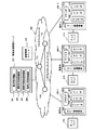
図1に本発明による多地点会議システムの第1の実施形態の構成図を示す。図1において、100は多段のマルチキャストルータ110によりマルチキャスト機能を備えたIPネットワーク(IPマルチネットワーク)であり、該IPネットワーク100上に、端末状態監視サーバ200、通信制御ユニット300、端末A400−1、端末B400−2、端末C400−3が接続されている。
【0013】
各端末400−1〜400−3は、2つもしくはそれ以上(本実施例では2つとする)の映像・音声等のデコーダ401と1つのエンコーダ、ブラウザ403、GUI制御機能404を有する。端末利用者は、端末状態監視サーバ200にアクセスする手段としてブラウザ403を使用する。例えば、利用者はブラウザ403により、端末状態監視サーバ200にアクセスし、送信・受信ともに行う端末か、受信のみを行う端末かを通知する。GUI制御機能404は、端末状態監視サーバ200より送信される送信者情報に応じて、ディスプレイ410の表示画面を制御する機能を有する。なお、各端末400−1〜400−3は、他にキーボードやマウス等を有するが、図1では省略してある。また、端末は勿論、3台に限らない。
【0014】
端末状態監視サーバ200は、任意の端末からの送信・受信ともに行うか、受信のみを行うかの要求を受け付け、それを会議を主催する端末へ通知する要求受付機能201と、会議を主催する端末からの端末選択状態(選択情報)を通信制御ユニット300に通知する選択状態通知機能202と、定期的に全端末に対して、各チャネルの通信者情報を通知する通信者情報通知機能203と、各端末の状態(送信・受信ともに行う端末か、受信のみを行う端末かなど)を管理する端末状態管理機能204を有する。
【0015】
通信制御ユニット300は、多地点会議の発呼等の呼制御信号を制御する機能を有する。この通信制御ユニット300は端末状態監視サーバ200からの選択情報を元に、端末の呼制御信号を変更する。
【0016】
会議を主催する端末(例えば、端末A400−1)は、ブラウザ403により端末状態監視サーバ200にアクセスし、GUI制御機能404により他の端末の通知状況を表示する。利用者がこの通知状況を元に、どの端末を送信・受信ともに行う端末にするか、どの端末を受信のみを行う端末にするかを選択することで、この会議を主催する端末は、ブラウザ403により端末状態監視サーバ200にアクセスし、端末の選択状態(選択情報)を通知する。端末状態監視サーバ200は、会議を主催する端末(例えば、端末A400−1)より受信した選択情報を通信制御ユニット300に通知し、通信制御ユニット300はその選択情報に基づき、全端末400−1〜400−3に対し、送信チャネル、受信チャネルの変更を通知し、発信要求のあった端末の音声・映像を全端末に配信する。
【0017】
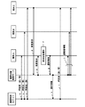
図2に、本実施例における端末状態監視サーバ200、通信制御ユニット300、各端末400−1〜400−3間の処理フローの一例を示す。
【0018】
図2において、会議開催時は400−1の端末Aが会議を主催する端末(講師)とし、400−2、400−3の端末B,Cからの映像・音声等を受信するとともに、端末B,Cに対して送信も行う端末とする。端末B,Cは端末Aからの映像・音声等を受信するのみの端末とする。以下では、会議中において、端末Cが受信のみを行う端末から送信・受信ともに行う端末へ変化する場合の例を説明する。
【0019】
まず、多地点会議開始時において、通信制御ユニット300は、SDP(Session Description Protocol、SIPで定義されているセッション記述プロトコル)を用いて、例えば、以下の情報を含む呼を各端末A、B、Cに設定する(ステップa、b、c)。
【0020】
端末A400−1には、
送信用チャネルとして
S=Session SDP
C=IN IP4 224.1.1.1
m=video 10000 RTP/AVP 33
a=rtpmap:33 MP2T/90000
a=sendonly
I=端末Aのユーザ名
また、受信用チャネルとして
S=Session SDP
C=IN IP4 224.1.1.1
m=video 10000 RTP/AVP 33
a=rtpmap:33 MP2T/90000
a=recvonly
I=端末Aのユーザ名
が設定されたINVITEをSDPで送信する(ステップa)。
【0021】
端末B400−2には、
受信用チャネルとして
S=Session SDP
C=IN IP4 224.1.1.1
m=video 10000 RTP/AVP 33
a=rtpmap:33 MP2T/90000
a=recvonly
I=端末Aのユーザ名
が設定されたINVITEをSDPで送信する(ステップb)。
【0022】
同様に、端末C400−3には、
受信用チャネルとして
S=Session SDP
C=IN IP4 224.1.1.1
m=video 10000 RTP/AVP 33
a=rtpmap:33 MP2T/90000
a=recvonly
I=端末Aのユーザ名
が設定されたINVITEをSDPで送信する(ステップc)。
【0023】
端末C400−3は、会議中において、ブラウザ403により端末状態監視サーバ200に対して、受信のみを行う端末から送信・受信ともに行う端末へと変わることを通知(発言要求)する(ステップd)。
【0024】
端末状態監視サーバ200は、要求受付機能201により端末C400−3からの通知(発言要求)を受け付け、会議を主催する端末A400−1に対し、端末C400−3が受信のみを行う端末から送信・受信ともに行う端末へと変わることを通知する(ステップe)。
【0025】
会議を主催する端末A400−1は、ブラウザ403により発言要求管理サーバ200からの通知(端末Cの発言要求)を受信し、GUI制御機能404により通知状況をディスプレイ410に表示する。そして、利用者が端末Cを受信のみを行う端末から送信・受信ともに行う端末へと変化することを許可すると、この会議を主催する端末A400−1は、改めてどの端末を送信・受信ともに行う端末にするか、どの端末を受信のみを行う端末にするかを選択し(ステップf)、この選択した状態(選択情報)をブラウザ403により端末状態監視サーバ200ヘ通知する(ステップg)。この例では、端末AとCが送信・受信とも行う端末、端末Bが受信のみ行う端末の選択情報が通知される。
【0026】
端末状態監視サーバ200は、会議を主催する端末A400−1から通知された情報(選択情報)を要求受付機能201により受信して、選択状態通知機能202により、この通知された情報を元に、どの端末を送信・受信ともに行う端末とし、どの端末を受信のみを行う端末とするかの情報を通信制御ユニット300に通知する(ステップh)。ここでは、端末AとCは送信・受信とも行う端末、端末Bは受信のみ行う端末の選択情報が通知される。
【0027】
通信制御ユニット300は、端末状態監視サーバ200から通知された情報を元に、全端末400−1〜400−3に対し、SDPで再びINVITEを送信する(ステップi、j、k)。
【0028】
例えば、端末A400−1に対しては、
送信用チャネルとして
S=Session SDP
C=IN IP4 224.1.1.1
m=video 10000 RTP/AVP 33
a=rtpmap:33 MP2T/90000
a=sendonly
I=端末Aのユーザ名
受信用チャネル1として
S=Session SDP
C=IN IP4 224.1.1.1
m=video 10000 RTP/AVP 33
a=rtpmap:33 MP2T/90000
a=recvonly
I=端末Aのユーザ名
受信用チャネル2として
S=Session SDP
C=IN IP4 224.1.1.2
m=video 10000 RTP/AVP 33
a=rtpmap:33 MP2T/90000
a=recvonly
I=端末Cのユーザ名
が設定されたINVITEをSDPで送信する(ステップi)。
【0029】
端末Bに対しては、
受信用チャネル1として
S=Session SDP
C=IN IP4 224.1.1.1
m=video 10000 RTP/AVP 33
a=rtpmap:33 MP2T/90000
a=recvonly
I=端末Aのユーザ名
受信用チャネル2として
S=Session SDP
C=IN IP4 224.1.1.2
m=video 10000 RTP/AVP 33
a=rtpmap:33 MP2T/90000
a=recvonly
I=端末Cのユーザ名
が設定されたINVITEをSDPで送信する(ステップj)。
【0030】
端末Cに対しては、
送信用チャネルとして
S=Session SDP
C=IN IP4 224.1.1.2
m=video 10000 RTP/AVP 33
a=rtpmap:33 MP2T/90000
a=sendonly
I=端末Aのユーザ名
受信用チャネル1として
S=Session SDP
C=IN IP4 224.1.1.1
m=video 10000 RTP/AVP 33
a=rtpmap:33 MP2T/90000
a=recvonly
I=端末Aのユーザ名
受信用チャネル2として
S=Session SDP
C=IN IP4 224.1.1.2
m=video 10000 RTP/AVP 33
a=rtpmap:33 MP2T/90000
a=recvonly
I=端末Cのユーザ名
が設定されたINVITEをSDPで送信する(ステップk)。
【0031】
一方、各端末400−1〜400−3における複数の受信チャネルと、受信チャネル毎の送信側端末との対応付けを可能とするため、端末状態監視サーバ200は、通信者情報通信機能203により定期的に、端末側にチャネル毎の端末識別信号として、最新の送信チャネル情報が設定されたSDPを含むINFOを全端末400−1〜400−3に送信する(ステップl)。
【0032】
送信情報としては、端末A,B,C全てに対し、例えば以下の情報のSDPを含むINFOが送られる。
受信用チャネル1として
S=Session SDP
C=IN IP4 224.1.1.1
I=端末Aのユーザ名
受信用チャネル2として
S=Session SDP
C=IN IP4 224.1.1.2
I=端末Cのユーザ名
これにより、空きチャネルであったマルチキャストIPアドレス224.1.1.2は端末Cが送信し始めたことを全端末400−1〜400−3で把握でき、受信チャネル毎の送信側端末との対応付けが可能となる。
【0033】
図3に、端末B400−2におけるGUI制御機能404による画面表示の切り替え例を示す。図2のステップlにおいて、端末状態監視サーバ200から送信された通信者情報(送信者情報)を受信した端末B400−2は、そのGUI制御機能404により、マルチキャストIPアドレス224.1.1.2は端末Cが送信し始め、受信チャネル数が増えたことにより、表示画面を図3(A)から(B)へと表示を切り替える制御を行う。
【0034】
〈実施例2〉
図4に本発明による多地点会議システムの第2の実施形態の構成図を示す。本実施例は、多地点会議開始時に予め全端末に搭載された映像・音声等のデコード数の受信チャネルを割り当てることで、映像・音声等の発信・受信をともに行う端末と、受信のみを行う端末の切替えを更に短時間で可能とするものである。
【0035】
図4において、システム全体の構成は基本的に図1と同様である。即ち、端末状態監視サーバ200、通信制御ユニット300、端末A400−1、端末B400−2,端末C400−3がマルチキャスト機能を有するIPネットワーク100により接続されている。
【0036】
各端末400−1〜400−3は、2つもしくはそれ以上(本実施例では2つ)の映像・音声等のデコーダ401と1つのエンコーダ402を有し、さらにブラウザ403、GUI制御機能404を有する。端末利用者は端末状態監視サーバ200にアクセスする手段としてブラウザ403を使用する。GUI制御機能404は端末状態監視サーバ200より送信される送信者情報に応じて、ディスプレイ410の表示画面を制御する機能を有する。なお、各端末400−1〜400−3は、他にキーボードやマウス等を有するが、図4でも省略する。また、端末は3台に限らない。
【0037】
端末状態監視サーバ200は、任意の端末からの送信・受信ともに行うか、受信のみを行うかの要求を受け付け、それを会議を主催する端末へ通知する要求受付機能201と、会議を主催する端末からの端末選択状態(選択情報)を通信制御ユニット300に通知する選択状態通知機能202と、定期的に全端末に対して、各チャネルの通信者情報を通知する通信者情報通知機能303と、各端末の状態(送信・受信ともに行う端末か、受信のみを行う端末かなど)を管理する端末状態管理機能204を有する。
【0038】
通信制御ユニット300は、多地点会議の発呼等の呼制御信号を制御する機能を有する。この通信制御ユニット300は端末状態監視サーバ200からの選択情報を元に、端末の呼制御信号を変更する。
【0039】
会議を主催する端末(例えば、端末A400−1)は、ブラウザ403により端末状態監視サーバ200にアクセスし、GUI制御機能404により他の端末の通知状況を表示する。利用者がこの通知状況を元に、どの端末を送信・受信ともに行う端末にするか、どの端末を受信のみを行う端末にするかを選択することで、会議を主催する端末は、ブラウザにより端末状態監視サーバ200にアクセスし、端末の選択状態(選択情報)を通知する。端末状態監視サーバ200は、会議を主催する端末より受信した選択情報を通信制御ユニット300に通知する。通信制御ユニット300はその選択情報に基づき、通信開始時に全端末に割り当てた受信チャネルの中より必要なチャネルを選択し、発信要求のあった端末の音声・映像を全端末に配信する。
【0040】
図5に、本実施例における端末状態監視サーバ200、通信制御ユニット300、各端末400−1〜400−3間の処理フローの一例を示す。
【0041】
図5においても、会議開催時において400−1の端末Aが会議を主催する端末(講師)とし、400−2、400−3の端末B,Cからの映像・音声等を受信するとともに、端末B,Cに対して送信も行う端末とする。端末B,Cは端末Aからの映像・音声等を受信するのみの端末とする。以下では、会議中において、端末Cが受信のみを行う端末から送信・受信ともに行う端末へ変化する場合の例を説明する。
【0042】
本実施例では、先の実施例1と異なり、会議開催時において、通信制御ユニット300は全端末400−1〜400−3に以下のような2つの受信チャネルの割り当てを行う。割り当てるチャネルについては、SDP(Session Description Protocol、SIPで定義されているセッション記述プロトコル)を用いて呼を設定する(ステップa、b、c)。
【0043】
例えば、端末A400−1には、
送信用チャネル1として
S=Session SDP
C=IN IP4 224.1.1.1
m=video 10000 RTP/AVP 33
a=rtpmap:33 MP2T/90000
a=sendonly
I=端末Aのユーザ名
また、受信用チャネル1として
S=Session SDP
C=IN IP4 224.1.1.1
m=video 10000 RTP/AVP 33
a=rtpmap:33 MP2T/90000
a=recvonly
I=端末Aのユーザ名
さらに受信用チャネル2として
S=Session SDP
C=IN IP4 224.1.1.2
m=video 10000 RTP/AVP 33
a=rtpmap:33 MP2T/90000
a=recvonly
I=空欄
が設定されたINVTEをSDPで送信する(ステップa)。
【0044】
端末B400−2には、 受信:ch1(i=A)、ch2
受信用チャネル1として
S=Session SDP
C=IN IP4 224.1.1.1
m=video 10000 RTP/AVP 33
a=rtpmap:33 MP2T/90000
a=recvonly
I=端末Aのユーザ名
また、受信用チャネル2として
S=Session SDP
C=IN IP4 224.1.1.2
m=video 10000 RTP/AVP 33
a=rtpmap:33 MP2T/90000
a=recvonly
I=空欄
が設定されたINVTEをSDPで送信する(ステップb)。
【0045】
同様に端末C400−3には、 受信:ch1(i=A)、ch2受信用チャネル1として
S=Session SDP
C=IN IP4 224.1.1.1
m=video 10000 RTP/AVP 33
a=rtpmap:33 MP2T/90000
a=recvonly
I=端末Aのユーザ名
また、受信用チャネル2として
S=Session SDP
C=IN IP4 224.1.1.2
m=video 10000 RTP/AVP 33
a=rtpmap:33 MP2T/90000
a=recvonly
I=空欄
が設定されたINVITEをSDPで送信する(ステップc)。
【0046】
このように、会議開催時、全端末400−1〜400−3に、その搭載されたデコーダ数の2つの受信チャネルの割り当てが行われ、そのうちの受信用チャネル2は空きチャネルとして設定される。
【0047】
端末C400−3は、会議中において、ブラウザ403により端末状態監視サーバ200に対して、受信のみを行う端末から送信・受信ともに行う端末へと変わることを通知(発言要求)する(ステップd)。
【0048】
端末状態監視サーバ200は、要求受付機能201により端末C400−3からの通知(発言要求)を受け付け、会議を主催する端末A400−1に対し、端末C400−3が受信のみを行う端末から送信・受信ともに行う端末へと変わることを通知する(ステップe)。
【0049】
会議を主催する端末A400−1は、ブラウザ403により端末状態監視サーバ200からの通知(端末Cの発言要求)を受信し、GUI制御機能404により通知状況をディスプレイ410に表示する。そして、利用者が端末Cを受信のみを行う端末から送信・受信ともに行う端末へと変化することを許可すると、この会議を主催する端末A400−1は、改めてどの端末を送信・受信ともに行う端末にするか(ここでは端末A,C)、どの端末を受信のみを行う端末にするか(ここでは端末B)を選択し(ステップf)、この選択した端末の状態(選択情報)を端末状態監視サーバ200ヘ通知する(ステップg)。
【0050】
端末状態監視サーバ200は、会議を主催する端末A400−1から通知された情報を要求受付機能201により受信して、選択状態通知機能202により、この通知された情報を元に、どの端末を送信・受信とともに行う端末とし、どの端末を受信のみを行う端末とするかの情報を通信制御ユニット300に通知する(ステップh)。ここでは、端末AとCは送信・受信とも行う端末、端末Bは受信のみ行う端末の選択情報が通知される。
【0051】
通知制御ユニット200は、受信のみを行う端末から送信・受信とも行う端末にかわった端末C400−3に対し、SDPで、例えば以下の情報が改定されたINVITEを送信する(ステップj)。
送信用チャネル1として
S=Session SDP
C=IN IP4 224.1.1.2
m=video 10000 RTP/AVP 33
a=rtpmap:33 MP2T/90000
a=sendonly
I=端末Cのユーザ名
受信用チャネル1として
S=Session SDP
C=IN IP4 224.1.1.1
m=video 10000 RTP/AVP 33
a=rtpmap:33 MP2T/90000
a=recvonly
I=端末Aのユーザ名
また、受信用チャネル2として
S=Session SDP
C=IN IP4 224.1.1.2
m=video 10000 RTP/AVP 33
a=rtpmap:33 MP2T/90000
a=recvonly
I=端末Cのユーザ名
各端末400−1〜400−3における複数の受信チャネルと、受信チャネル毎の送信側端末との対応付けを可能とするため、端末状態監視サーバ200は、通信者情報通信機能203により、定期的に、端末側にチャネル毎の端末識別信号として、最新の送信チャネル情報が設定されたSDPを含むINFOを全端末400−1〜400−3に送信する(ステップj)。
【0052】
送信情報としては、端末A、B、C全てに対し、例えば以下の情報のSDPを含むINFOが送られる。
受信用チャネル1として
S=Session SDP
C=IN IP4 224.1.1.1
I=端末Aのユーザ名
受信用チャネル2として
S=Session SDP
C=IN IP4 224.1.1.2
I=端末Cのユーザ名
これにより、空きチャネルであったマルチキャストIPアドレス224.1.2は端末C送信し始めたことを全端末400−1〜400−3で把握でき、受信チャネル毎の送信側端末との対応付けが可能なる。
【0053】
図6に、端末B400−2における、GUI制御機能404による画面表示の切り替え例を示す。
図5のステップjにおいて、端末状態監視サーバ200から送信された通信情報(送信情報)を受信した端末B400−2は、そのGUI制御機能404により、マルチキャストIPアドレス224.1.1.2は端末Cが送信し始め、受信チャネル数が増えたことにより、表示画面を図6(A)から(B)へと表示を切り替える制御を行う。
【0054】
以上、本発明の実施形態を説明したが、本発明はこれに限られるものではない。例えば、端末状態監視サーバ200は、ある端末からの送信・受信ともに行うか、受信のみを行うかの要求を受付けた場合、それを会議を主催する端末に問い合わせることなく通信制御ユニット300に通知することも可能である。また、IPネットワークは一般にネットワーク、マルチキャスト機能は同報配信等の上位概念とすることも可能である。
【0055】
【発明の効果】
以上説明したように、本発明によれば、多地点会議における送信のみを行う端末と、送信・受信を行う端末との切替えを短時間で行うことを可能とし、また送信者情報を受信した端末側においては、送信者情報を元に自由なGUI制御が可能となる。
【図面の簡単な説明】
【図1】本発明による多地点会議システムの第1の実施形態の全体構成図である。
【図2】本発明の第1の実施形態の処理フロー図である。
【図3】本発明の第1の実施形態のGUI制御例を示す図である。
【図4】本発明による多地点会議システムの第2の実施形態の全体構成図である。
【図5】本発明の第2の実施形態の処理フロー図である。
【図6】本発明の第2の実施形態のGUI制御例を示す図である。
【符号の説明】
100 IPマルチキャストネットワーク
200 端末状態監視サーバ
201 要求受付機能
202 選択状態通知機能
203 通信者情報通信機能
204 端末状態管理機能
300 通信制御ユニット
400−1〜400−3 端末
401 デコーダ
402 エンコーダ
403 ブラウザ
404 GUI制御機能
410 ディスプレイ[0001]
TECHNICAL FIELD OF THE INVENTION
The present invention relates to a method for transmitting video / audio transmitted from each terminal between a plurality of channels of video / audio decoders and a plurality of terminals having at least one encoder on a network such as an IP network having a multicast function. The present invention relates to a multipoint conferencing method for realizing a multipoint conference by broadcasting IP multicast or the like to all terminals participating in a conference, a terminal status monitoring server and a terminal used for the method.
[0002]
[Prior art]
Conventionally, on a network, having a communication control unit that controls a call control signal such as a call of a multipoint conference, between a plurality of terminals having a decoder of at least one encoder and video and audio decoder of a plurality of channels, In a system that realizes a multipoint conference by broadcasting video and audio transmitted from each terminal to all terminals participating in the conference, a multipoint conference with a partner terminal exceeding the number of decoders of the terminal is required. It is difficult to hold a conference, there is no other way but to increase the number of decoders on the terminal, and even when increasing the number of decoders on the terminal side, due to the increase in the amount of data accompanying the higher quality of data such as video and audio, The processing load on the terminal increases, and there is a limit to increasing the number of decoders.
[0003]
In the conventional method, a control signal such as a call for a multipoint conference is transmitted to a specific terminal during the multipoint conference when a communication state changes, such as a change in a transmission channel or a reception channel. The control unit needs to communicate call control signals to all terminals, and as the number of terminals participating in the multipoint conference increases, the number of control signals increases, and as a result, transmission and reception of control signals The time has been long, and it has not been possible to operate the conference smoothly, and the number of terminals that can simultaneously participate in the multipoint conference has been limited.
[0004]
On the other hand, on an IP network having a multicast function, SIP
Although a multipoint conference method such as a 3rd party call method using (Session Initiation Protocol) has been proposed (for example, see Non-Patent Document 1), one INVITE process per terminal is actually INVITE, 200OK. , ACK messages, the total number of messages is three times as large, and there is a limit to switching between a terminal that performs only reception in a multipoint conference and a terminal that performs transmission and reception in a short time.
(Non-patent literature)
Internet Engineering Task Force Internet Draft
Draft-ietf-sipping-conferencing-models-01. txt July1,2002
(Http://www.ietf.org/Internet-drafts/draft-iet-sipping-conferencing-models-01.txt)
[0005]
[Problems to be solved by the invention]
SUMMARY OF THE INVENTION The present invention has been made to solve the above-described problems of the related art, and an object of the present invention is to provide a communication control unit for controlling a call control signal such as a call for a multipoint conference on a network, and a video / multiple-channel video / video. A multipoint conference is realized by connecting an audio decoder and multiple terminals with at least one encoder, and broadcasting the video and audio from each terminal to all terminals participating in the conference among multiple terminals. In this case, it is possible to switch between a terminal that performs only reception in a multipoint conference and a terminal that performs transmission and reception in a short time.
[0006]
[Means for Solving the Problems]
The present invention provides a function of receiving a request to perform both transmission and reception or only reception from a terminal on a network in which the communication control unit and a plurality of terminals are connected, and notifies the communication control unit of the received request. A terminal status monitoring server having a function and a function of periodically notifying all terminals of the communication information of each channel is arranged. The communication control unit changes the call control signal of the terminal based on the notification from the terminal state monitoring server. As a result, the total number of messages with the terminal can be minimized, and switching between a terminal that performs both transmission and reception of video and audio and a terminal that performs only reception can be performed in a short time.
[0007]
In addition, the present invention allocates reception channels of the number of video / audio decoders mounted on all terminals in advance at the start of the multipoint conference, and the communication control unit performs transmission / reception based on a notification from the terminal status monitoring server. The call control signal of the terminal which has issued the request for performing both the reception and the reception only is changed. As a result, switching between a terminal that performs both transmission and reception of video and audio and a terminal that performs only reception can be further reduced.
[0008]
Further, according to the present invention, the terminal status monitoring server notifies a specific terminal of a request whether to perform both transmission and reception or only reception from the terminal, and which terminal transmits / receives or receives from the specific terminal. The communication control unit is configured to receive selection information as to whether the communication control unit is to be used only.
[0009]
Further, the present invention has a GUI control function for controlling a display screen on the terminal side according to the sender information of each channel transmitted from the terminal state monitoring server on the terminal side. The display screen is controlled accordingly.
[0010]
BEST MODE FOR CARRYING OUT THE INVENTION
Hereinafter, embodiments of the present invention will be described with reference to the drawings. In the following embodiment, it is assumed that a multipoint conference using SIP is held on an IP network having a multicast function. Also, as the multipoint conference, it is assumed that the video / audio media from each SIP terminal is mutually distributed between the SIP terminals by IP multicast, and only the call control signal meets the communication control unit and is communicated. I do.
[0011]
However, the present invention is not limited to SIP-specific ones. It can also be used in other communication protocols, such as the H.323 (ITU-T recommendation that specifies the transmission and reception specifications and signaling methods for voice, video, and data communication on the LAN).
[0012]
<Example 1>
FIG. 1 shows a configuration diagram of a first embodiment of a multipoint conference system according to the present invention. In FIG. 1,
[0013]
Each of the terminals 400-1 to 400-3 has two or more (in this embodiment, two)
[0014]
The terminal status monitoring server 200 receives a request to perform both transmission and reception or only reception from an arbitrary terminal, and a
[0015]
The
[0016]
The terminal hosting the conference (for example, terminal A400-1) accesses the terminal status monitoring server 200 using the
[0017]
FIG. 2 illustrates an example of a processing flow between the terminal status monitoring server 200, the
[0018]
In FIG. 2, at the time of holding a conference, the terminal A 400-1 is a terminal (instructor) for hosting the conference, receives video / audio from the terminals B and C 400-2 and 400-3, and receives the terminal B. , C. Terminals B and C are terminals that only receive video / audio from terminal A. Hereinafter, an example in which the terminal C changes from a terminal that performs only reception to a terminal that performs both transmission and reception during a conference will be described.
[0019]
First, at the start of the multipoint conference, the
[0020]
Terminal A400-1 includes:
As a transmission channel
S = Session SDP
C = IN IP4 224.1.1.1
m = video 10000 RTP / AVP 33
a = rtpmap: 33 MP2T / 90000
a = sendonly
I = user name of terminal A
Also, as a receiving channel
S = Session SDP
C = IN IP4 224.1.1.1
m = video 10000 RTP / AVP 33
a = rtpmap: 33 MP2T / 90000
a = recvonly
I = user name of terminal A
Is transmitted by SDP (step a).
[0021]
In the terminal B400-2,
As a receiving channel
S = Session SDP
C = IN IP4 224.1.1.1
m = video 10000 RTP / AVP 33
a = rtpmap: 33 MP2T / 90000
a = recvonly
I = user name of terminal A
Is transmitted by SDP (step b).
[0022]
Similarly, terminal C400-3 has
As a receiving channel
S = Session SDP
C = IN IP4 224.1.1.1
m = video 10000 RTP / AVP 33
a = rtpmap: 33 MP2T / 90000
a = recvonly
I = user name of terminal A
Is transmitted by SDP (step c).
[0023]
During the conference, the terminal C400-3 uses the
[0024]
The terminal status monitoring server 200 receives the notification (speech request) from the terminal C400-3 by the
[0025]
The terminal A 400-1 that hosts the conference receives the notification (speak request from the terminal C) from the statement request management server 200 via the
[0026]
The terminal status monitoring server 200 receives the information (selection information) notified from the terminal A 400-1 hosting the conference by the
[0027]
The
[0028]
For example, for terminal A400-1,
As a transmission channel
S = Session SDP
C = IN IP4 224.1.1.1
m = video 10000 RTP / AVP 33
a = rtpmap: 33 MP2T / 90000
a = sendonly
I = user name of terminal A
As channel 1 for reception
S = Session SDP
C = IN IP4 224.1.1.1
m = video 10000 RTP / AVP 33
a = rtpmap: 33 MP2T / 90000
a = recvonly
I = user name of terminal A
As reception channel 2
S = Session SDP
C = IN IP4 224.1.1.2
m = video 10000 RTP / AVP 33
a = rtpmap: 33 MP2T / 90000
a = recvonly
I = user name of terminal C
Is transmitted by SDP (step i).
[0029]
For terminal B,
As channel 1 for reception
S = Session SDP
C = IN IP4 224.1.1.1
m = video 10000 RTP / AVP 33
a = rtpmap: 33 MP2T / 90000
a = recvonly
I = user name of terminal A
As reception channel 2
S = Session SDP
C = IN IP4 224.1.1.2
m = video 10000 RTP / AVP 33
a = rtpmap: 33 MP2T / 90000
a = recvonly
I = user name of terminal C
Is transmitted by SDP (step j).
[0030]
For terminal C,
As a transmission channel
S = Session SDP
C = IN IP4 224.1.1.2
m = video 10000 RTP / AVP 33
a = rtpmap: 33 MP2T / 90000
a = sendonly
I = user name of terminal A
As channel 1 for reception
S = Session SDP
C = IN IP4 224.1.1.1
m = video 10000 RTP / AVP 33
a = rtpmap: 33 MP2T / 90000
a = recvonly
I = user name of terminal A
As reception channel 2
S = Session SDP
C = IN IP4 224.1.1.2
m = video 10000 RTP / AVP 33
a = rtpmap: 33 MP2T / 90000
a = recvonly
I = user name of terminal C
Is transmitted by SDP (step k).
[0031]
On the other hand, in order to enable a plurality of receiving channels in each of the terminals 400-1 to 400-3 to be associated with a transmitting terminal for each receiving channel, the terminal status monitoring server 200 Specifically, INFO including the SDP in which the latest transmission channel information is set is transmitted to all terminals 400-1 to 400-3 as a terminal identification signal for each channel (step l).
[0032]
As the transmission information, an INFO including, for example, the following information SDP is transmitted to all of the terminals A, B, and C.
As channel 1 for reception
S = Session SDP
C = IN IP4 224.1.1.1
I = user name of terminal A
As reception channel 2
S = Session SDP
C = IN IP4 224.1.1.2
I = user name of terminal C
As a result, the multicast IP address 224.1.1.2, which was an empty channel, can be grasped by all the terminals 400-1 to 400-3 that the terminal C has begun to transmit, and the multicast IP address 224.1.1.2 can be identified with the transmitting terminal for each receiving channel. Correspondence becomes possible.
[0033]
FIG. 3 shows an example of screen display switching by the
[0034]
<Example 2>
FIG. 4 shows a configuration diagram of a second embodiment of the multipoint conference system according to the present invention. In the present embodiment, at the start of the multipoint conference, by assigning a reception channel of the number of decodes of video / audio etc. mounted in advance to all terminals, a terminal that performs both transmission / reception of video / audio, and performs reception only The terminal can be switched in a shorter time.
[0035]
4, the configuration of the entire system is basically the same as that of FIG. That is, the terminal status monitoring server 200, the
[0036]
Each of the terminals 400-1 to 400-3 has two or more (two in this embodiment) video /
[0037]
The terminal status monitoring server 200 receives a request to perform both transmission and reception or only reception from an arbitrary terminal, and a
[0038]
The
[0039]
The terminal hosting the conference (for example, terminal A400-1) accesses the terminal status monitoring server 200 using the
[0040]
FIG. 5 illustrates an example of a processing flow among the terminal status monitoring server 200, the
[0041]
In FIG. 5 as well, at the time of holding the conference, the terminal A 400-1 serves as a terminal (instructor) for hosting the conference, receives video / audio from the terminals B and C 400-2 and 400-3, Terminals that also transmit to B and C. Terminals B and C are terminals that only receive video / audio from terminal A. Hereinafter, an example in which the terminal C changes from a terminal that performs only reception to a terminal that performs both transmission and reception during a conference will be described.
[0042]
In the present embodiment, unlike the first embodiment, at the time of holding a conference, the
[0043]
For example, terminal A400-1 has
As transmission channel 1
S = Session SDP
C = IN IP4 224.1.1.1
m = video 10000 RTP / AVP 33
a = rtpmap: 33 MP2T / 90000
a = sendonly
I = user name of terminal A
Also, as reception channel 1
S = Session SDP
C = IN IP4 224.1.1.1
m = video 10000 RTP / AVP 33
a = rtpmap: 33 MP2T / 90000
a = recvonly
I = user name of terminal A
Furthermore, as reception channel 2
S = Session SDP
C = IN IP4 224.1.1.2
m = video 10000 RTP / AVP 33
a = rtpmap: 33 MP2T / 90000
a = recvonly
I = blank
Is transmitted by SDP (step a).
[0044]
Terminal B400-2 receives: ch1 (i = A), ch2
As channel 1 for reception
S = Session SDP
C = IN IP4 224.1.1.1
m = video 10000 RTP / AVP 33
a = rtpmap: 33 MP2T / 90000
a = recvonly
I = user name of terminal A
Also, as reception channel 2
S = Session SDP
C = IN IP4 224.1.1.2
m = video 10000 RTP / AVP 33
a = rtpmap: 33 MP2T / 90000
a = recvonly
I = blank
Is transmitted by SDP (step b).
[0045]
Similarly, for terminal C400-3, reception: ch1 (i = A) and ch2 reception channel 1
S = Session SDP
C = IN IP4 224.1.1.1
m = video 10000 RTP / AVP 33
a = rtpmap: 33 MP2T / 90000
a = recvonly
I = user name of terminal A
Also, as reception channel 2
S = Session SDP
C = IN IP4 224.1.1.2
m = video 10000 RTP / AVP 33
a = rtpmap: 33 MP2T / 90000
a = recvonly
I = blank
Is transmitted by SDP (step c).
[0046]
As described above, at the time of holding a conference, two reception channels of the number of installed decoders are allocated to all the terminals 400-1 to 400-3, and the reception channel 2 of them is set as an idle channel.
[0047]
During the conference, the terminal C400-3 uses the
[0048]
The terminal status monitoring server 200 receives the notification (speech request) from the terminal C400-3 by the
[0049]
The terminal A 400-1 that hosts the conference receives the notification (request for speech from the terminal C) from the terminal status monitoring server 200 by the
[0050]
The terminal status monitoring server 200 receives the information notified from the terminal A 400-1 hosting the conference by the
[0051]
The notification control unit 200 transmits, for example, INVITE in which the following information has been revised by SDP from the terminal that performs only reception to the terminal C400-3 that has changed to the terminal that performs both transmission and reception (step j).
As transmission channel 1
S = Session SDP
C = IN IP4 224.1.1.2
m = video 10000 RTP / AVP 33
a = rtpmap: 33 MP2T / 90000
a = sendonly
I = user name of terminal C
As channel 1 for reception
S = Session SDP
C = IN IP4 224.1.1.1
m = video 10000 RTP / AVP 33
a = rtpmap: 33 MP2T / 90000
a = recvonly
I = user name of terminal A
Also, as reception channel 2
S = Session SDP
C = IN IP4 224.1.1.2
m = video 10000 RTP / AVP 33
a = rtpmap: 33 MP2T / 90000
a = recvonly
I = user name of terminal C
In order to enable a plurality of receiving channels in each of the terminals 400-1 to 400-3 to be associated with a transmitting terminal for each receiving channel, the terminal status monitoring server 200 periodically performs Next, an INFO including the SDP in which the latest transmission channel information is set is transmitted to all the terminals 400-1 to 400-3 as a terminal identification signal for each channel to the terminals (step j).
[0052]
As the transmission information, an INFO including, for example, the SDP of the following information is transmitted to all of the terminals A, B, and C.
As channel 1 for reception
S = Session SDP
C = IN IP4 224.1.1.1
I = user name of terminal A
As reception channel 2
S = Session SDP
C = IN IP4 224.1.1.2
I = user name of terminal C
This allows all the terminals 400-1 to 400-3 to know that the multicast IP address 224.1.2, which was an empty channel, has begun to be transmitted by the terminal C, and the reception channel is associated with the transmission side terminal for each reception channel. Possible.
[0053]
FIG. 6 illustrates an example of switching screen display by the
In step j of FIG. 5, the terminal B 400-2 having received the communication information (transmission information) transmitted from the terminal state monitoring server 200 uses the
[0054]
The embodiment of the present invention has been described above, but the present invention is not limited to this. For example, when the terminal status monitoring server 200 receives a request to perform both transmission and reception or only reception from a certain terminal, the terminal status monitoring server 200 notifies the
[0055]
【The invention's effect】
As described above, according to the present invention, a terminal that performs only transmission in a multipoint conference and a terminal that performs transmission and reception can be switched in a short time, and a terminal that receives sender information On the side, free GUI control is possible based on the sender information.
[Brief description of the drawings]
FIG. 1 is an overall configuration diagram of a first embodiment of a multipoint conference system according to the present invention.
FIG. 2 is a processing flowchart of the first embodiment of the present invention.
FIG. 3 is a diagram illustrating a GUI control example according to the first embodiment of the present invention.
FIG. 4 is an overall configuration diagram of a second embodiment of a multipoint conference system according to the present invention.
FIG. 5 is a processing flowchart according to a second embodiment of the present invention.
FIG. 6 is a diagram illustrating an example of GUI control according to the second embodiment of the present invention.
[Explanation of symbols]
100 IP multicast network
200 Terminal status monitoring server
201 Request reception function
202 Selection status notification function
203 Communication information function
204 Terminal status management function
300 Communication control unit
400-1 to 400-3 terminal
401 decoder
402 encoder
403 Browser
404 GUI control function
410 display
Claims (7)
通常は特定の端末の映像・音声を会議に参加する全端末に配信し、必要に応じ前記特定の端末以外の端末からの映像・音声の配信を可能とする多地点会議方法であって、
前記ネットワーク上に、端末からの送信・受信とも行うか受信のみを行うかの要求を受付ける機能と、受付けた要求を前記通信制御ユニットに通知する機能と、定期的に全端末に対して、各チャネルの通信者情報を通知する機能を持つ端末状態監視サーバを配置し、
前記通信制御ユニットは、前記端末状態監視サーバからの通知を元に端末の呼制御信号を変更し、
映像・音声の発信と受信とも行う端末と、受信のみを行う端末の切替えを可能とすることを特徴とする多地点会議方法。On the network, a communication control unit for controlling a call control signal such as a multipoint conference call, a plurality of terminals having a plurality of video / audio decoders and at least one encoder are connected, and the plurality of terminals are connected. In a multipoint conference method for realizing a multipoint conference by broadcasting video and audio from each terminal to all terminals participating in the conference,
Usually a video / audio of a specific terminal is distributed to all terminals participating in the conference, and a multi-point conference method that enables distribution of video / audio from a terminal other than the specific terminal as necessary,
On the network, a function of receiving a request whether to perform only transmission and reception or only reception from a terminal, a function of notifying the received request to the communication control unit, and periodically for all terminals, A terminal status monitoring server that has the function of notifying the communication information of the channel is located,
The communication control unit changes a call control signal of a terminal based on a notification from the terminal state monitoring server,
A multipoint conference method, wherein a terminal that performs both transmission and reception of video and audio and a terminal that performs only reception can be switched.
多地点会議開始時に予め全端末に搭載された映像・音声のデコーダ数の受信チャネルを割り当て、
前記通信制御ユニットは、前記端末状態監視サーバからの通知を元に、送信・受信とも行うか受信のみを行うかの要求を発した端末の呼制御信号を変更することを特徴とする多地点会議方法。The multipoint conference method according to claim 1,
At the start of the multipoint conference, the receiving channels of the number of video / audio decoders mounted on all terminals are allocated in advance,
The multipoint conference, wherein the communication control unit changes a call control signal of a terminal that has issued a request to perform both transmission and reception or only reception based on a notification from the terminal state monitoring server. Method.
前記端末状態監視サーバは、端末からの送信・受信とも行うか受信のみを行うかの要求を特定の端末に通知し、該特定の端末からどの端末を送信・受信共あるいは受信のみとするかの選択情報を受信して、該選択情報を前記通信制御ユニットに通知することを特徴とする多地点会議方法。The multipoint conference method according to claim 1 or 2,
The terminal status monitoring server notifies a specific terminal of a request to perform transmission / reception or only reception from a terminal, and determines which terminal is to be used for both transmission / reception or reception only from the specific terminal. A multipoint conference method, comprising receiving selection information and notifying the communication control unit of the selection information.
端末側は、前記端末状態監視サーバから送信される各チャネルの送信者情報に応じて、GUI制御を行うことを特徴とする多地点会議方法。The multipoint conference method according to any one of claims 1 to 3,
A multipoint conference method, wherein the terminal performs GUI control according to sender information of each channel transmitted from the terminal status monitoring server.
マルチキャスト機能を有するIPネットワーク上に、端末状態監視サーバ、通信制御ユニット、複数の端末を接続し、前記複数の端末の間で、各端末からの映像・音声を会議に参加する全端末にIPマルチキャストすることによって多地点会議を実現することを特徴とする多地点会議方法。In the multipoint conference method according to any one of claims 1 to 4,
A terminal status monitoring server, a communication control unit, and a plurality of terminals are connected on an IP network having a multicast function, and among the plurality of terminals, video / audio from each terminal is transmitted to all terminals participating in a conference by IP multicast. A multi-point conference method characterized by realizing a multi-point conference by performing a multi-point conference.
Priority Applications (1)
| Application Number | Priority Date | Filing Date | Title |
|---|---|---|---|
| JP2002353138A JP2004187108A (en) | 2002-12-04 | 2002-12-04 | Multipoint conference method, terminal status monitoring server and terminal |
Applications Claiming Priority (1)
| Application Number | Priority Date | Filing Date | Title |
|---|---|---|---|
| JP2002353138A JP2004187108A (en) | 2002-12-04 | 2002-12-04 | Multipoint conference method, terminal status monitoring server and terminal |
Publications (1)
| Publication Number | Publication Date |
|---|---|
| JP2004187108A true JP2004187108A (en) | 2004-07-02 |
Family
ID=32754499
Family Applications (1)
| Application Number | Title | Priority Date | Filing Date |
|---|---|---|---|
| JP2002353138A Pending JP2004187108A (en) | 2002-12-04 | 2002-12-04 | Multipoint conference method, terminal status monitoring server and terminal |
Country Status (1)
| Country | Link |
|---|---|
| JP (1) | JP2004187108A (en) |
Cited By (5)
| Publication number | Priority date | Publication date | Assignee | Title |
|---|---|---|---|---|
| GB2412536A (en) * | 2004-03-19 | 2005-09-28 | Nec Personal Products Ltd | Multipoint conferencing in an IP network |
| JP2006121316A (en) * | 2004-10-20 | 2006-05-11 | Mitsubishi Electric Corp | Monitor system |
| JP2007311983A (en) * | 2006-05-17 | 2007-11-29 | Nippon Telegr & Teleph Corp <Ntt> | Consulting support system and method therefor |
| JP2010504022A (en) * | 2006-09-14 | 2010-02-04 | タンドベルク・テレコム・エイ・エス | Method and apparatus for dynamic streaming storage configuration |
| US8229487B2 (en) | 2005-08-02 | 2012-07-24 | Nec Corporation | PTT server, gate apparatus, communication system, program and communication method |
-
2002
- 2002-12-04 JP JP2002353138A patent/JP2004187108A/en active Pending
Cited By (9)
| Publication number | Priority date | Publication date | Assignee | Title |
|---|---|---|---|---|
| GB2412536A (en) * | 2004-03-19 | 2005-09-28 | Nec Personal Products Ltd | Multipoint conferencing in an IP network |
| GB2412536B (en) * | 2004-03-19 | 2006-05-03 | Nec Personal Products Ltd | Multipoint conferencing system employing ip network and its configuration method |
| JP2006121316A (en) * | 2004-10-20 | 2006-05-11 | Mitsubishi Electric Corp | Monitor system |
| JP4704005B2 (en) * | 2004-10-20 | 2011-06-15 | 三菱電機株式会社 | Monitoring system |
| US8229487B2 (en) | 2005-08-02 | 2012-07-24 | Nec Corporation | PTT server, gate apparatus, communication system, program and communication method |
| JP2007311983A (en) * | 2006-05-17 | 2007-11-29 | Nippon Telegr & Teleph Corp <Ntt> | Consulting support system and method therefor |
| JP4565658B2 (en) * | 2006-05-17 | 2010-10-20 | 日本電信電話株式会社 | Consulting support system and method |
| JP2010504022A (en) * | 2006-09-14 | 2010-02-04 | タンドベルク・テレコム・エイ・エス | Method and apparatus for dynamic streaming storage configuration |
| US8260854B2 (en) | 2006-09-14 | 2012-09-04 | Cisco Technology, Inc. | Method and device for dynamic streaming archiving configuration |
Similar Documents
| Publication | Publication Date | Title |
|---|---|---|
| JP5579598B2 (en) | Computer-implemented method, memory and system | |
| US7257641B1 (en) | Multipoint processing unit | |
| EP2452487B1 (en) | Controlling multi-party communications | |
| EP1885111B1 (en) | Conference server | |
| EP1487149B1 (en) | VoIP system and method using multicast packet communication | |
| US20120134301A1 (en) | Wide area voice environment multi-channel communications system and method | |
| US20080137643A1 (en) | Accessing call control functions from an associated device | |
| US8073956B2 (en) | Multimedia communications using preferred devices | |
| US20130097333A1 (en) | Methods and apparatuses for unified streaming communication | |
| EP2011324A2 (en) | Network resource optimization in a video conference | |
| EP2130346B1 (en) | Media stream setup in a group communication system | |
| KR20050101506A (en) | System and method for monitoring push to talk over cellular simultaneous session | |
| CN101997866A (en) | Distributed media mixing and conferencing in IP networks | |
| US20100034201A1 (en) | Method and apparatus for unicast and multicast media processing | |
| US20110187813A1 (en) | Method of Connecting Mesh-Topology Video Sessions to a Standard Video Conference Mixer | |
| JP2013219777A (en) | System and method for providing phone related services to multiple devices using upnp on home network | |
| JP4958174B2 (en) | Media switching method, session management server, terminal and program in group communication | |
| CN110460603B (en) | Multimedia file transmission method, terminal, server, system and storage medium | |
| WO2016114967A1 (en) | Systems and methods for adaptive context-aware control of multimedia communication sessions | |
| WO2021017807A1 (en) | Call connection establishment method, first terminal, server, and storage medium | |
| JP2005311670A (en) | Terminal, system and method for television conference, and program therefor | |
| JP2004187108A (en) | Multipoint conference method, terminal status monitoring server and terminal | |
| CN101594623B (en) | Method and equipment for monitoring call made via voice over Internet protocol | |
| CN115842809A (en) | Data stream real-time transmission method and conference system |
Legal Events
| Date | Code | Title | Description |
|---|---|---|---|
| A621 | Written request for application examination |
Free format text: JAPANESE INTERMEDIATE CODE: A621 Effective date: 20050118 |
|
| A131 | Notification of reasons for refusal |
Free format text: JAPANESE INTERMEDIATE CODE: A131 Effective date: 20061108 |
|
| A02 | Decision of refusal |
Free format text: JAPANESE INTERMEDIATE CODE: A02 Effective date: 20070619 |