JP2004178791A - Hard disk drive memory system - Google Patents
Hard disk drive memory system Download PDFInfo
- Publication number
- JP2004178791A JP2004178791A JP2003386120A JP2003386120A JP2004178791A JP 2004178791 A JP2004178791 A JP 2004178791A JP 2003386120 A JP2003386120 A JP 2003386120A JP 2003386120 A JP2003386120 A JP 2003386120A JP 2004178791 A JP2004178791 A JP 2004178791A
- Authority
- JP
- Japan
- Prior art keywords
- hard disk
- disk drive
- connector
- storage system
- library
- Prior art date
- Legal status (The legal status is an assumption and is not a legal conclusion. Google has not performed a legal analysis and makes no representation as to the accuracy of the status listed.)
- Pending
Links
Images


Classifications
-
- G—PHYSICS
- G11—INFORMATION STORAGE
- G11B—INFORMATION STORAGE BASED ON RELATIVE MOVEMENT BETWEEN RECORD CARRIER AND TRANSDUCER
- G11B33/00—Constructional parts, details or accessories not provided for in the other groups of this subclass
- G11B33/12—Disposition of constructional parts in the apparatus, e.g. of power supply, of modules
- G11B33/125—Disposition of constructional parts in the apparatus, e.g. of power supply, of modules the apparatus comprising a plurality of recording/reproducing devices, e.g. modular arrangements, arrays of disc drives
- G11B33/126—Arrangements for providing electrical connections, e.g. connectors, cables, switches
-
- G—PHYSICS
- G11—INFORMATION STORAGE
- G11B—INFORMATION STORAGE BASED ON RELATIVE MOVEMENT BETWEEN RECORD CARRIER AND TRANSDUCER
- G11B17/00—Guiding record carriers not specifically of filamentary or web form, or of supports therefor
- G11B17/22—Guiding record carriers not specifically of filamentary or web form, or of supports therefor from random access magazine of disc records
- G11B17/225—Guiding record carriers not specifically of filamentary or web form, or of supports therefor from random access magazine of disc records wherein the disks are transferred from a fixed magazine to a fixed playing unit using a moving carriage
-
- G—PHYSICS
- G11—INFORMATION STORAGE
- G11B—INFORMATION STORAGE BASED ON RELATIVE MOVEMENT BETWEEN RECORD CARRIER AND TRANSDUCER
- G11B25/00—Apparatus characterised by the shape of record carrier employed but not specific to the method of recording or reproducing, e.g. dictating apparatus; Combinations of such apparatus
- G11B25/04—Apparatus characterised by the shape of record carrier employed but not specific to the method of recording or reproducing, e.g. dictating apparatus; Combinations of such apparatus using flat record carriers, e.g. disc, card
- G11B25/043—Apparatus characterised by the shape of record carrier employed but not specific to the method of recording or reproducing, e.g. dictating apparatus; Combinations of such apparatus using flat record carriers, e.g. disc, card using rotating discs
-
- G—PHYSICS
- G11—INFORMATION STORAGE
- G11B—INFORMATION STORAGE BASED ON RELATIVE MOVEMENT BETWEEN RECORD CARRIER AND TRANSDUCER
- G11B33/00—Constructional parts, details or accessories not provided for in the other groups of this subclass
- G11B33/12—Disposition of constructional parts in the apparatus, e.g. of power supply, of modules
- G11B33/125—Disposition of constructional parts in the apparatus, e.g. of power supply, of modules the apparatus comprising a plurality of recording/reproducing devices, e.g. modular arrangements, arrays of disc drives
- G11B33/127—Mounting arrangements of constructional parts onto a chassis
- G11B33/128—Mounting arrangements of constructional parts onto a chassis of the plurality of recording/reproducing devices, e.g. disk drives, onto a chassis
-
- G—PHYSICS
- G06—COMPUTING; CALCULATING OR COUNTING
- G06F—ELECTRIC DIGITAL DATA PROCESSING
- G06F3/00—Input arrangements for transferring data to be processed into a form capable of being handled by the computer; Output arrangements for transferring data from processing unit to output unit, e.g. interface arrangements
- G06F3/06—Digital input from, or digital output to, record carriers, e.g. RAID, emulated record carriers or networked record carriers
- G06F2003/0697—Digital input from, or digital output to, record carriers, e.g. RAID, emulated record carriers or networked record carriers device management, e.g. handlers, drivers, I/O schedulers
-
- G—PHYSICS
- G06—COMPUTING; CALCULATING OR COUNTING
- G06F—ELECTRIC DIGITAL DATA PROCESSING
- G06F3/00—Input arrangements for transferring data to be processed into a form capable of being handled by the computer; Output arrangements for transferring data from processing unit to output unit, e.g. interface arrangements
- G06F3/06—Digital input from, or digital output to, record carriers, e.g. RAID, emulated record carriers or networked record carriers
- G06F3/0601—Interfaces specially adapted for storage systems
Landscapes
- Automatic Disk Changers (AREA)
Abstract
Description
本発明は、包括的には記憶システムに関し、より詳細にはハードディスクドライブ記憶システムに関する。 The present invention relates generally to storage systems, and more particularly to hard disk drive storage systems.
記憶システム、すなわちオートチェンジャは、既知の場所にデータカートリッジを格納し、かつ所望のデータカートリッジを検索して、データカートリッジに対してデータの書き込みおよび/または読み出しを行うことができるようにするために一般に用いられる。したがって、大量のコンピュータ読み取り可能データは、多数のデータカートリッジに記憶され、記憶システムに(例えばネットワーク上で)接続された1つまたは複数のコンピュータによりアクセスされ得る。 Storage systems, or autochangers, are commonly used to store a data cartridge in a known location and retrieve the desired data cartridge so that data can be written to and / or read from the data cartridge. Used. Thus, large amounts of computer readable data may be stored on multiple data cartridges and accessed by one or more computers connected to the storage system (eg, over a network).
かかる記憶システムは、1つまたは複数の格納マガジンおよびカートリッジ読み取り/書き込みデバイスを含み得る。格納マガジンは、データカートリッジの格納場所としての役割を果たし、読み取り/書き込みデバイス(複数可)は、データカートリッジに記憶されたデータへのアクセスを可能にする。記憶システムは、ピッカアセンブリと連動するコントローラ、ならびに記憶システムに格納されたデータカートリッジ間でピッカアセンブリを移動させるための駆動システムも含み得る。 Such a storage system may include one or more storage magazines and cartridge read / write devices. The storage magazine serves as a storage location for the data cartridge, and the read / write device (s) provides access to data stored on the data cartridge. The storage system may also include a controller associated with the picker assembly, as well as a drive system for moving the picker assembly between data cartridges stored in the storage system.
例として、コントローラがある特定のデータカートリッジにアクセスせよとの命令を受け取った場合、コントローラは、駆動システムがピッカアセンブリを所望のデータカートリッジの場所まで移動させるようにする。次に、ピッカアセンブリはデータカートリッジを取り出し、それを読み取り/書き込みデバイスへ運ぶ。ピッカアセンブリは、読み取り/書き込み動作に続いて、格納マガジンへデータカートリッジを戻すように動作することもできる。 By way of example, if the controller receives an instruction to access a particular data cartridge, the controller causes the drive system to move the picker assembly to the desired data cartridge location. Next, the picker assembly removes the data cartridge and transports it to the read / write device. The picker assembly can also operate to return the data cartridge to the storage magazine following a read / write operation.
通常のデータカートリッジのアクセスタイミング(time)は比較的遅い。例えば、データカートリッジが読み取り/書き込みデバイスへ運ばれてしまうと、読み取り/書き込みヘッドを位置決めしてから読み取り/書き込み動作を開始できるまでに、さらに4〜6分かかる可能性がある。ハードディスクドライブのアクセスタイミングははるかに速い。例えば、通常のハードディスクドライブに設けられた読み取り/書き込みヘッドの位置決めでは、読み取り/書き込み動作が開始できるまでに約10〜15ミリ秒しかかからない。 The access timing (time) of a normal data cartridge is relatively slow. For example, if the data cartridge is transported to a read / write device, it may take another 4-6 minutes before the read / write operation can begin after the read / write head is positioned. Hard disk drive access timing is much faster. For example, in positioning a read / write head provided in a typical hard disk drive, it takes only about 10 to 15 milliseconds before a read / write operation can be started.
最近まで、ハードディスクドライブは一般に、データカートリッジよりも高価であった。しかし最近では、ハードディスクドライブのコストはデータカートリッジのコストに近づいてきているため、ハードディスクドライブは過去に比べて大容量ストレージソリューションとしてより一般的になりつつある。例えば、ハードディスクドライブは通常、RAID(すなわち、独立ディスクランダム配列(random array of independent disks))記憶システムに提供される。 Until recently, hard disk drives were generally more expensive than data cartridges. Recently, however, hard disk drives are becoming more popular as mass storage solutions than in the past, as the cost of hard disk drives is approaching the cost of data cartridges. For example, hard disk drives are typically provided in RAID (ie, random array of independent disks) storage systems.
RAID記憶システムで用いられるハードディスクドライブは、使用時でなくても常時接続されている。「常時接続」システムに設けられたハードディスクドライブは、損耗(例えば熱からの)、さらには永久的な損傷またはデータ損失(例えば電源サージ中の)を受けやすい。さらに、かかるシステムのハードディスクドライブのそれぞれを結合するために、多数のケーブル配線が必要である。 Hard disk drives used in RAID storage systems are always connected even when not in use. Hard disk drives provided in "always on" systems are susceptible to wear (eg, from heat) as well as permanent damage or data loss (eg, during power surges). In addition, multiple cabling is required to couple each of the hard disk drives in such a system.
本発明によると、ハードディスクドライブ記憶システムの一実施形態は、ライブラリ、ライブラリに取り付けられた少なくとも1つの格納デバイス、およびライブラリに取り付けられた少なくとも1つのコネクタを備える。少なくとも1つのハードディスクドライブは、少なくとも1つの格納デバイスに収納可能であり、かつ代替的に、少なくとも1つのコネクタに隣接して収納可能である。ピッカアセンブリは、ライブラリに移動可能に取り付けられ、少なくとも1つの記憶デバイスと少なくとも1つのコネクタとの間で少なくとも1つのハードディスクドライブを運ぶ。 According to the present invention, one embodiment of a hard disk drive storage system comprises a library, at least one storage device attached to the library, and at least one connector attached to the library. The at least one hard disk drive can be housed in at least one storage device, and, alternatively, can be housed adjacent to the at least one connector. The picker assembly is movably mounted to the library and carries at least one hard disk drive between at least one storage device and at least one connector.
記憶システムにおける複数のハードディスクドライブからのデータにアクセスする方法の一実施形態は、記憶システムに複数のハードディスクドライブを格納すること、記憶システムにおいて複数のハードディスクドライブの1つをコネクタに移送すること、移送されたハードディスクドライブをコネクタに接続することであって、それにより読み取り/書き込み動作を行う、接続すること、および読み取り/書き込み動作に続いて、接続されているハードディスクドライブをコネクタから外すこと、を含む。 One embodiment of a method of accessing data from a plurality of hard disk drives in a storage system includes storing the plurality of hard disk drives in a storage system, transferring one of the plurality of hard disk drives to a connector in the storage system, transferring the data. Connecting the connected hard disk drive to the connector, thereby performing and connecting the read / write operation, and, following the read / write operation, disconnecting the connected hard disk drive from the connector. .
本発明のハードディスクドライブ記憶システムにハードディスクドライブを使用することにより、ユーザは、ドライブのデータに高速アクセスすることができる。ハードディスクドライブは、使用時以外には物理的に外されることにより、ハードディスクドライブが常時接続されている場合に生じ得る損耗および/または永久的な損傷またはデータ損失を低減することもまた有利である。さらに、ハードディスクドライブ記憶システムに必要なケーブル配線は、「常時接続」システムよりも少なくなる。 By using a hard disk drive in the hard disk drive storage system of the present invention, a user can access the data of the drive at high speed. It is also advantageous that the hard disk drive be physically removed except when in use to reduce wear and / or permanent damage or data loss that may occur when the hard disk drive is permanently connected. . In addition, the hard disk drive storage system requires less cabling than an "always on" system.
本発明の例示的な目下好ましい実施形態を図面に示す。 Illustrative, presently preferred embodiments of the invention are illustrated in the drawings.
ハードディスクドライブ記憶システム10が、いくつかのハードディスクドライブ12に大量のコンピュータ読み取り可能データを記憶するために用いられ得るものとして、本発明の実施形態に従って本明細書中に図示および記載される。1人または複数人のユーザは、コンピュータ15から(例えば、ネットワーク上、直接接続等で)適当な制御回路(例えばコントローラ19)を介して記憶システム10(図1)と繋がることができる。ハードディスクドライブ記憶システム10は、いくつかの格納デバイス16(例えば格納マガジン)および少なくとも1つのデータアクセスデバイス18が内部に取り付けられたライブラリ14を含み得る。格納デバイス16およびデータアクセスデバイス18は、図1に示す略U字形の構成等の、任意の適当な構成で配置されてよい。
A hard disk
図1ではライブラリ14の格納デバイス16およびデータアクセスデバイス18は特定の構成で配置されて示されているが、他の適当な変更も本発明の範囲内にあると考えられることに留意されたい。さらに、ライブラリ14に設けられる格納デバイス16およびデータアクセスデバイス18の数は、設計に関する様々な考慮事項に応じて決めることができる。かかる考慮事項は、データにアクセスする際の周波数を含み得るが、これに限定されない。他の考慮事項としては、ライブラリ14の物理的な寸法が含まれ得る。
It should be noted that while FIG. 1 shows the
ライブラリ14には、ピッカアセンブリ28も設けられ得る。概して、ピッカアセンブリ28は、ハードディスクドライブ12の1つと係合して、ハードディスクドライブ12を(例えば格納デバイス16の1つから)引き出し、ライブラリ14内でハードディスクドライブ12を移送し、意図した目的位置(例えばデータアクセスデバイス18)でデータカートリッジを排出するようになっている。
ライブラリ14にはガイドシステム24を取り付けることができ、ガイドシステム24は、格納デバイス16およびデータアクセスデバイス18に隣接する移動経路26を画定する。一実施形態では、ガイドシステム24は、ギヤトラックが取り付けられたレールを含み得る。しかしながら、ガイドシステム24の他の実施形態もまた、本発明の範囲内にあるものと考えられ、本発明の教示を熟知した当業者であれば容易に提供することができる。
The
ピッカアセンブリ28は、ガイドシステム24と連動し、ライブラリ14のハードディスクドライブ12にアクセスするために移動経路26に沿って移動可能である。例えば、ピッカアセンブリ28は、ギヤアセンブリと連動する駆動モータを有するアクチュエータアセンブリ30を含み得る。ギヤアセンブリは、ガイドシステム24のギヤトラックと係合して、ライブラリ14においてガイドシステム24上でピッカアセンブリ28を移動させることができる。
適当なコントローラ19がピッカアセンブリ28と連動し、ライブラリ14内で、例えばデータアクセスデバイス18と格納デバイス16との間で、ハードディスクドライブ12を移送する。例示のために、ピッカアセンブリ28を図1において位置17、17’、および17’’で示す。ピッカアセンブリ28は、位置17および17’’で格納デバイス16に隣接して位置するように示され、位置17’でデータアクセスデバイス18に隣接して位置するように示される。
A
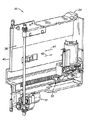
本発明の教示に従って用いられ得るピッカアセンブリ28の一実施形態は、図2においてより詳細に示され、図3において側部パネル32を取り外した状態でも示される。ピッカアセンブリ28は、ハードディスクドライブ12を収納するサイズであるキャビティ36を画定するハウジング34を含み得る。プランジ機構すなわち「サムアセンブリ(thumb assembly)」38がハウジング34に摺動可能に取り付けられていることにより、サムアセンブリ38をハウジング34のカートリッジアクセス端部40に対して、概ね矢印41および42でそれぞれ示す方向に進退移動させることができる。
One embodiment of a
現在既知であるかまたは将来開発され得る広範囲に及ぶ他のピッカアセンブリもまた、本発明の範囲内にあると考えられることに留意されたい。したがって、本発明は、本明細書中で図示および記載する特定のピッカアセンブリ28との使用に限定されるとみなされるべきではない。
Note that a wide range of other picker assemblies now known or that may be developed in the future are also considered to be within the scope of the present invention. Therefore, the present invention should not be considered limited to use with the
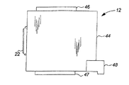
本発明のハードディスクドライブ記憶システム10と共に用いるように設けられ得るハードディスクドライブ12の1つの一実施形態は、図4(a)〜図4(c)においてより詳細に示される。ハードディスクドライブ12はハウジング44を含み得る。1つまたは複数のガイド部材46、47が、ハードディスクドライブ12のハウジング44に取り付けられ得るか、またはハウジング44と一体的に形成され得る。
One embodiment of a
ガイド部材46、47は、対応する格納デバイスガイド52(図5)と協働し、ガイド52は、ガイド52に対するハードディスクドライブ12の挿入および引き出しが行われている時にハードディスクドライブ12を位置合わせするために格納デバイス16に設けられ得る。これにより、ハードディスクドライブ12は、固定されることなくガイド52に対する挿入および引き出しが容易に行われ得る。
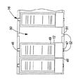
格納デバイス16の一実施形態を図5に示すが、ここでは格納デバイスは格納マガジンである。かかる実施形態によると、格納デバイス16は、いくつかの格納室50が内部に形成されたハウジング51を含むことができ、格納室50はそれぞれ、少なくとも1つのハードディスクドライブ12を収納するサイズである。好ましい一実施形態では、格納デバイス16はライブラリ14から取り外し可能である。かかる実施形態によると、格納デバイス16の1つを容易に取り外して、別の格納デバイス16と取り替えることができる。
One embodiment of the
上述のように、格納デバイス16はガイド52を含むことができ、ガイド52は、ガイド部材46、47と協働して、格納デバイス16内のハードディスクドライブ12を位置合わせする。一例では、ガイド52は、ハウジング51内に形成された凹部またはチャネルを含み得る。あるいは、ガイド52はレール(例えばシリンダまたはロッド)を含み得る。当然、ガイド52は、ハードディスクドライブ12に取り付けられたガイド部材46、47と協働するような任意の適当な形状であってよい。いずれにせよ、ガイド部材46、47はガイド52に沿って容易に摺動し、内部に形成された格納室50内にハードディスクドライブ12をガイドする。
As described above, the
ガイド部材46、47は、ハードディスクドライブ12の任意の適当な位置に取り付けることができる。例えば、ガイド部材46、47は、ハードディスクドライブ12の側部に設けてもよい。かかる実施形態では、対応するガイド52、56は、格納デバイス16およびデータアクセスデバイス18の側壁または隔壁に設けることができる。
The
ガイド部材46、47は、剛性材料(例えば硬質のプラスチックまたは金属)からできていることが好ましいが、任意の適当な材料から製造することができる。さらに、ガイド部材46、47は、任意の適当な形状であってよい。例えば、ガイド部材46、47は、図4(a)〜図4(c)に示すもののように、「フィン」または「ブレード」であってよい。しかしながら、本発明の教示を熟知した当業者には明らかとなるように、他の実施形態も本発明の範囲内にあると考えられる。例えば、他の実施形態では、ガイド部材46、47は、略「T字形」であってもよく、または、格納デバイス16およびデータアクセスデバイス18の円筒ガイドと協働する円形の開口を形成してもよい。
The
図4(a)および図4(b)に示すように、ハードディスクドライブ12は、ハウジング44に取り付けられた対応コネクタ22も含み得る。このコネクタ22は、ハードディスクドライブ12からデータアクセスデバイス18(例えば対応するコネクタ20)への結合を提供する。データアクセスデバイス18のコネクタ20は、コントローラ19に結合され得るか、またはユーザのコンピュータに直接(例えばネットワーク上で)結合され得る。したがって、ハードディスクドライブ12は、データアクセスデバイス18に接続されると、ユーザのコンピュータに結合され得る。
As shown in FIGS. 4A and 4B, the
コネクタ22は、任意の適当なコネクタであってよい。一実施形態では、コネクタ22は、データ転送、電源、および接地用のピンを含む、複数の接続部すなわちピンを含み得る。さらに、コネクタ22は、データアクセスデバイス18の電源を停止させる必要なくハードディスクドライブ12を容易に接続することができるように、「ホットスワップ可能」コネクタであり得る。例えば、コネクタ22は、RAID記憶システムで用いられるもののような、容易に入手可能なSCA(single connector attachment)であり得る。SCAコネクタは、単一の80ピンコネクタで、従来の68ピンのデータ接続、4ピンの電源接続、およびコンフィギュレーションジャンパを提供する。しかしながら、コネクタ22の他の実施形態も本発明の範囲内にあると考えられることを理解されたい。
ハードディスクドライブ12は、ハウジング44に取り付けられた(またはハウジング44の一部として一体的に形成された)ブラケット部材48も含み得る。ブラケット部材48がピッカアセンブリ28のサムアセンブリ38と協働することにより、サムアセンブリ38がブラケット部材と係合して、ハードディスクドライブ12をデータアクセスデバイス18および格納デバイス16から引き出す。しかしながら、他の実施形態も本発明の範囲内にあると考えられる。例えば、ブラケット部材48の代わりに、ピッカアセンブリ28のサムアセンブリ38と協働するハードディスクドライブ12のハウジング44内にノッチが形成されてもよい。ピッカアセンブリ28が代替的な取り出し機構を含む場合、その取り出し機構と協働するためにブラケット部材48の適当な代替物を設けることもできる。
任意に、ハードディスクドライブ12には、機械可読表示(indicia)49(例えばバーコードラベル)を設けることができる。機械可読表示49は任意の適当な表示を含むことができ、本明細書中に図示および記載されるバーコードラベルに限定されないことを理解されたい。例えば、機械可読表示49は、トランスポンダを含み得る。いずれにせよ、機械可読表示49は、適当な読み取り機および制御回路を用いて読み取ることができ、ライブラリ14のデータカートリッジ12を識別するのに用いることができる。例えば、機械可読表示49がバーコードラベルである場合、ピッカアセンブリ28がライブラリ14の移動経路26に沿って移動する時にハードディスクドライブ12からバーコードラベルを読み取ることができるように、バーコードスキャナがピッカアセンブリ28に設けられ得る。あるいは、機械可読表示がトランスポンダである場合、それぞれの格納デバイス16およびデータアクセスデバイス18においてトランスポンダに隣接して誘導式の読み取り機(inductive reader)を設けて、トランスポンダを作動させてそこから情報を読み取るようにしてもよい。
Optionally, the
データアクセスデバイス18の一実施形態を図6により詳細に示す。データアクセスデバイス18は、1つまたは複数のコネクタ20が取り付けられたバックプレーン58を含み得る。バックプレーンに取り付けられるコネクタ20の数は、設計に関する考慮事項に応じて変わり得る。例えば、バックプレーン58に設けられるコネクタ20が多いほど、同時にアクセスできるハードディスクドライブ12の数が多くなる。
One embodiment of the
コネクタ20はそれぞれ、電源(図示せず)に結合されており、電源は、ハードディスクドライブ12がデータアクセスデバイス18においてコネクタ20に結合されている場合、ハードディスクドライブ12に電力を供給する。コネクタ20はまた、ユーザ(複数可)により要求された読み取り/書き込み動作を実行するために用いることができるデータ転送接続を(例えば制御回路19を介して)提供する。
Each of the
データアクセスデバイス18は、ハウジング54も含み得る。ハウジング54は、格納デバイス16のハウジング51と同様に製造することができる。実際、いくつかの実施形態では、データアクセスデバイス18は、ライブラリ14から取り外し可能である(例えば、それによって容易に取り替えることができる)。
コネクタガイド56は、格納デバイス16におけるガイド52と同様に機能して、ハードディスクドライブ12がガイド56に挿入される時にハードディスクドライブ12を位置合わせするようにする。さらに、ガイド56は、ハードディスクドライブ12のコネクタ22をデータアクセスデバイス18のバックプレーン58に取り付けられたコネクタ20と位置合わせして、コネクタ20、22を互いに結合することができるようにする。ここでも、ガイド56は、ハードディスクドライブ12のガイド部材46、47と協働する任意の適当な形状であってよい。
The connector guide 56 functions similarly to the
本発明の一実施形態によると、ハードディスクドライブ記憶システム10は以下のように動作することができる。ハードディスクドライブ記憶システム10に(例えばネットワーク接続されたコンピュータを介して)接続されたユーザが読み取り/書き込み動作を要求すると、コントローラ(図示せず)がピッカアセンブリ28に、格納デバイス16の1つからハードディスクドライブ12の1つを取り出すように伝える。
According to one embodiment of the present invention, hard disk
ピッカアセンブリ28は、格納デバイス16の選択したデータデータカートリッジ12に隣接するように、位置決めレール24上で移動経路26に沿って移動する。データアクセスデバイス18を図7に示すが、格納デバイス16からハードディスクドライブ12の1つを取り出すというピッカアセンブリ28の動作は、例示のために同様である。ピッカアセンブリ28がライブラリ14内で適切に位置付けられると、プランジ機構38が、ハードディスクドライブ12と係合するまで矢印41の方向へ移動する。プランジ機構38の配置は、プランジ機構38がその完全伸長位置またはその付近にある場合に、ハードディスクドライブ12のブラケット部材48と係合するような配置である。
ハードディスクドライブ12がプランジ機構38により係合された後に、プランジ機構38は、図7において矢印42で概ね示すように方向を逆転する。これにより、係合したハードディスクドライブ12は格納デバイス16から引き出され、ピッカアセンブリ28のハウジング40により画定されるカートリッジ収納キャビティ36に収納される。ピッカアセンブリ28をライブラリ14内の別の場所へ移動させるのに十分な量だけハードディスクドライブ12がピッカアセンブリ28のカートリッジ収納キャビティ36内に収納されるまで、プランジ機構38は後退し続ける。
After the
ハードディスクドライブ12が取り出されると、ピッカアセンブリ28はデータアクセスデバイス18まで移動する。次に、ピッカアセンブリ28は、図7に示すように矢印41の方向にプランジ機構38を移動させることにより、ハードディスクドライブ12を排出する。ハードディスクドライブ12のガイド部材46、47は、データアクセスデバイス18に形成されたガイド56と協働して、ガイド56においてハードディスクドライブ12を位置合わせする。ハードディスクドライブ12のコネクタ22がデータアクセスデバイス18のバックプレーン58のコネクタ20と接触し、次いでコネクタ20と(例えば互いに押し付けることにより)結合して、それによりハードディスクドライブ12が読み取り/書き込み動作可能になるように、プランジ機構38は矢印41の方向に移動し続ける。
When the
読み取り/書き込み動作中に、ピッカアセンブリ28は、記憶システム10内で他のハードディスクドライブ12を取り出し、かつ/または戻すために用いることができる。読み取り/書き込み動作に続いて、ピッカアセンブリ28はデータアクセスデバイス18まで戻され、ハードディスクドライブ12に隣接して位置付けられ得る(すなわち、ライブラリ14の他の場所へ移動していた場合)。次に、ピッカアセンブリ28は、上述のように、データアクセスデバイス18からのハードディスクドライブ12と係合するように動作し得る。ハードディスクドライブ12がデータアクセスデバイス18から引き出されると、コネクタ20、22は互いから係脱する。ピッカアセンブリ28をライブラリ14内の別の場所へ移動させるのに十分な量だけハードディスクドライブ12がピッカアセンブリ28のカートリッジ収納キャビティ36内に収納されるまで、プランジ機構38は後退し続ける。次に、ピッカアセンブリ28は、ハードディスクドライブ12を格納デバイス16へ戻すように動作し得る。
During read / write operations, the
本発明のハードディスクドライブ記憶システム10に使用するハードディスクドライブ12により、ユーザは、ドライブのデータに高速アクセスすることができることは明白であろう。ハードディスクドライブ12は、使用時以外には物理的に外されることにより、ハードディスクドライブ12が常時接続されている場合に生じ得る損耗および/または永久的な損傷またはデータ損失を低減することもまた有利である。さらに、ハードディスクドライブ記憶システム10に必要なケーブル配線は、「常時接続」システムよりも少ない。
It will be apparent that the
10 ハードディスクドライブ記憶システム
12 ハードディスクドライブ
14 ライブラリ
16 格納デバイス
20、22 コネクタ
28 ピッカアセンブリ
46,47 ガイド部材
52 格納デバイスガイド
56 コネクタガイド
10 Hard Disk
Claims (10)
前記ライブラリに取り付けられた少なくとも1つの格納デバイスと、
前記ライブラリに取り付けられた少なくとも1つのコネクタと、
前記少なくとも1つの格納デバイスと前記少なくとも1つのコネクタの近傍に収納可能である、少なくとも1つのハードディスクドライブと、
前記ライブラリに移動可能に取り付けられ、前記少なくとも1つの格納デバイスと前記少なくとも1つのコネクタとの間で前記少なくとも1つのハードディスクドライブを運ぶ、ピッカアセンブリとを備えることを特徴とするハードディスクドライブ記憶システム。 Library and
At least one storage device attached to the library;
At least one connector attached to the library;
At least one hard disk drive stowable proximate the at least one storage device and the at least one connector;
A hard disk drive storage system movably mounted to the library and carrying the at least one hard disk drive between the at least one storage device and the at least one connector.
前記記憶システムに前記複数のハードディスクドライブを格納し、
前記記憶システムにおいて前記複数のハードディスクドライブの1つをコネクタに移送し、
読み取り/書き込み動作を行うために、移送された前記ハードディスクドライブを前記コネクタに接続し、
前記読み取り/書き込み動作に続いて、接続されている前記ハードディスクドライブを前記コネクタから外すことを特徴とする方法。 A method for accessing data from a plurality of hard disk drives in a storage system, comprising:
Storing the plurality of hard disk drives in the storage system;
Transferring one of the plurality of hard disk drives to a connector in the storage system;
Connecting the transferred hard disk drive to the connector to perform a read / write operation;
Disconnecting the connected hard disk drive from the connector following the read / write operation.
Applications Claiming Priority (1)
| Application Number | Priority Date | Filing Date | Title |
|---|---|---|---|
| US10/303,415 US6909570B2 (en) | 2002-11-25 | 2002-11-25 | Hard disk drive storage system |
Publications (1)
| Publication Number | Publication Date |
|---|---|
| JP2004178791A true JP2004178791A (en) | 2004-06-24 |
Family
ID=32229929
Family Applications (1)
| Application Number | Title | Priority Date | Filing Date |
|---|---|---|---|
| JP2003386120A Pending JP2004178791A (en) | 2002-11-25 | 2003-11-17 | Hard disk drive memory system |
Country Status (3)
| Country | Link |
|---|---|
| US (1) | US6909570B2 (en) |
| EP (1) | EP1422713A3 (en) |
| JP (1) | JP2004178791A (en) |
Families Citing this family (41)
| Publication number | Priority date | Publication date | Assignee | Title |
|---|---|---|---|---|
| US6957291B2 (en) * | 2001-03-29 | 2005-10-18 | Quantum Corporation | Removable disk storage array emulating tape library having backup and archive capability |
| US20050152061A1 (en) * | 2003-10-31 | 2005-07-14 | Havard Hoelsaeter | Configurable storage system with swappable tape magazines and hard-disk magazines |
| US7505261B2 (en) * | 2004-03-18 | 2009-03-17 | Hewlett-Packard Development Company, L.P. | Electrical-optical signal conversion for automated storage systems |
| US20060178186A1 (en) * | 2005-02-04 | 2006-08-10 | Multimedia Games, Inc. | Configurable gaming machine and method for configuring games in a gaming machine |
| US20080126214A1 (en) * | 2005-10-26 | 2008-05-29 | Ballard Curtis C | Ordering supplies from an operator control panel of storage apparatus |
| DE102007011714B4 (en) * | 2007-03-09 | 2009-01-08 | Fujitsu Siemens Computers Gmbh | Memory plug-in component for a server rack |
| US7996174B2 (en) * | 2007-12-18 | 2011-08-09 | Teradyne, Inc. | Disk drive testing |
| US8549912B2 (en) | 2007-12-18 | 2013-10-08 | Teradyne, Inc. | Disk drive transport, clamping and testing |
| US8041449B2 (en) | 2008-04-17 | 2011-10-18 | Teradyne, Inc. | Bulk feeding disk drives to disk drive testing systems |
| US20090262455A1 (en) | 2008-04-17 | 2009-10-22 | Teradyne, Inc. | Temperature Control Within Disk Drive Testing Systems |
| US7945424B2 (en) | 2008-04-17 | 2011-05-17 | Teradyne, Inc. | Disk drive emulator and method of use thereof |
| US8117480B2 (en) | 2008-04-17 | 2012-02-14 | Teradyne, Inc. | Dependent temperature control within disk drive testing systems |
| US7848106B2 (en) | 2008-04-17 | 2010-12-07 | Teradyne, Inc. | Temperature control within disk drive testing systems |
| US8102173B2 (en) | 2008-04-17 | 2012-01-24 | Teradyne, Inc. | Thermal control system for test slot of test rack for disk drive testing system with thermoelectric device and a cooling conduit |
| US8238099B2 (en) | 2008-04-17 | 2012-08-07 | Teradyne, Inc. | Enclosed operating area for disk drive testing systems |
| US8160739B2 (en) | 2008-04-17 | 2012-04-17 | Teradyne, Inc. | Transferring storage devices within storage device testing systems |
| US8095234B2 (en) | 2008-04-17 | 2012-01-10 | Teradyne, Inc. | Transferring disk drives within disk drive testing systems |
| US8305751B2 (en) | 2008-04-17 | 2012-11-06 | Teradyne, Inc. | Vibration isolation within disk drive testing systems |
| JP2011524060A (en) | 2008-06-03 | 2011-08-25 | テラダイン、 インコーポレイテッド | How to handle storage devices |
| US8687356B2 (en) | 2010-02-02 | 2014-04-01 | Teradyne, Inc. | Storage device testing system cooling |
| US8628239B2 (en) | 2009-07-15 | 2014-01-14 | Teradyne, Inc. | Storage device temperature sensing |
| US7995349B2 (en) | 2009-07-15 | 2011-08-09 | Teradyne, Inc. | Storage device temperature sensing |
| US7920380B2 (en) | 2009-07-15 | 2011-04-05 | Teradyne, Inc. | Test slot cooling system for a storage device testing system |
| US8466699B2 (en) | 2009-07-15 | 2013-06-18 | Teradyne, Inc. | Heating storage devices in a testing system |
| US8116079B2 (en) | 2009-07-15 | 2012-02-14 | Teradyne, Inc. | Storage device testing system cooling |
| US8547123B2 (en) | 2009-07-15 | 2013-10-01 | Teradyne, Inc. | Storage device testing system with a conductive heating assembly |
| US9779780B2 (en) | 2010-06-17 | 2017-10-03 | Teradyne, Inc. | Damping vibrations within storage device testing systems |
| US8687349B2 (en) | 2010-07-21 | 2014-04-01 | Teradyne, Inc. | Bulk transfer of storage devices using manual loading |
| US9001456B2 (en) | 2010-08-31 | 2015-04-07 | Teradyne, Inc. | Engaging test slots |
| US9459312B2 (en) | 2013-04-10 | 2016-10-04 | Teradyne, Inc. | Electronic assembly test system |
| US10845410B2 (en) | 2017-08-28 | 2020-11-24 | Teradyne, Inc. | Automated test system having orthogonal robots |
| US10725091B2 (en) | 2017-08-28 | 2020-07-28 | Teradyne, Inc. | Automated test system having multiple stages |
| US11226390B2 (en) | 2017-08-28 | 2022-01-18 | Teradyne, Inc. | Calibration process for an automated test system |
| US10948534B2 (en) | 2017-08-28 | 2021-03-16 | Teradyne, Inc. | Automated test system employing robotics |
| US10983145B2 (en) | 2018-04-24 | 2021-04-20 | Teradyne, Inc. | System for testing devices inside of carriers |
| US10775408B2 (en) | 2018-08-20 | 2020-09-15 | Teradyne, Inc. | System for testing devices inside of carriers |
| US11867749B2 (en) | 2020-10-22 | 2024-01-09 | Teradyne, Inc. | Vision system for an automated test system |
| US11754596B2 (en) | 2020-10-22 | 2023-09-12 | Teradyne, Inc. | Test site configuration in an automated test system |
| US11953519B2 (en) | 2020-10-22 | 2024-04-09 | Teradyne, Inc. | Modular automated test system |
| US11754622B2 (en) | 2020-10-22 | 2023-09-12 | Teradyne, Inc. | Thermal control system for an automated test system |
| US11899042B2 (en) | 2020-10-22 | 2024-02-13 | Teradyne, Inc. | Automated test system |
Family Cites Families (14)
| Publication number | Priority date | Publication date | Assignee | Title |
|---|---|---|---|---|
| US4453188A (en) * | 1981-04-10 | 1984-06-05 | Amlyn Corporation | Disk drive |
| US4685095A (en) * | 1984-07-11 | 1987-08-04 | Filenet Corporation | Optical storage and retrieval device |
| US5041924A (en) * | 1988-11-30 | 1991-08-20 | Quantum Corporation | Removable and transportable hard disk subsystem |
| US5235474A (en) * | 1991-10-28 | 1993-08-10 | Advanced Digital Information Corporation | Apparatus and method for automatic storage of computer data |
| US5576911A (en) * | 1994-10-25 | 1996-11-19 | Sony Corporation | Cartridge locking mechanism and interface |
| US6104693A (en) * | 1998-03-20 | 2000-08-15 | Hewlett-Packard Company | Mounting system for cartridge plunge mechanism |
| EP1026688A3 (en) * | 1999-02-02 | 2001-06-13 | Siemens Information and Communication Networks Inc. | Removable integrated multiple internal disk drive subsystem |
| US6480350B1 (en) * | 1999-09-24 | 2002-11-12 | Michael J. Malone | Hard disk drive selector |
| US6305959B1 (en) * | 1999-12-30 | 2001-10-23 | Iomega Corporation | Electrical connector with lock |
| EP1235222A2 (en) * | 2001-02-15 | 2002-08-28 | Plasmon LMS, Inc. | System for hard disk drive library |
| US6512962B2 (en) * | 2001-04-26 | 2003-01-28 | International Business Machines Corporation | Cabling picker in a library of stationary memory devices |
| US6754768B2 (en) * | 2001-04-26 | 2004-06-22 | International Business Machines Corporation | Library of hard disk drives with transparent emulating interface |
| US6711580B2 (en) * | 2001-10-01 | 2004-03-23 | International Business Machines Corporation | Data management system, apparatus, and method to use buffered file marks |
| EP1481325A4 (en) * | 2002-02-05 | 2008-02-20 | Asaca Corp | Data storage system |
-
2002
- 2002-11-25 US US10/303,415 patent/US6909570B2/en not_active Expired - Lifetime
-
2003
- 2003-06-10 EP EP03013055A patent/EP1422713A3/en not_active Withdrawn
- 2003-11-17 JP JP2003386120A patent/JP2004178791A/en active Pending
Also Published As
| Publication number | Publication date |
|---|---|
| US20040100716A1 (en) | 2004-05-27 |
| EP1422713A2 (en) | 2004-05-26 |
| EP1422713A3 (en) | 2005-12-28 |
| US6909570B2 (en) | 2005-06-21 |
Similar Documents
| Publication | Publication Date | Title |
|---|---|---|
| JP2004178791A (en) | Hard disk drive memory system | |
| US5377121A (en) | Automated storage library having inventory at picker level | |
| JP3565273B2 (en) | Storage library with horseshoe structure | |
| US5819309A (en) | Automated tape cartridge library with accelerated calibration | |
| EP0341038B1 (en) | A method of operating a storage and retrieval mechanism | |
| US8868866B2 (en) | Configurable tape loader with internal hard-disk | |
| JP5495308B2 (en) | Library device, method for taking out and storing data cartridge | |
| US9053741B2 (en) | Storage cartridge and cartridge drive | |
| JP2009043406A (en) | Virtual magnetic tape drive library system | |
| US20040088482A1 (en) | Systems for storing data | |
| JP2003085852A (en) | Apparatus for transporting data cartridge | |
| EP1531467A2 (en) | Configurable storage system with swappable tape magazines and hard-disk magazines | |
| EP1820189B1 (en) | Extendable virtual autoloader systems and methods | |
| US6985328B2 (en) | One and three quarters inch form factor tape cartridge autoloader | |
| US8488269B2 (en) | Library apparatus | |
| WO1997029484A2 (en) | Automated tape cartridge library | |
| US7212470B2 (en) | Method and apparatus to transfer information between a host computer and one or more hard disks disposed in a data storage and retrieval system | |
| US7230792B2 (en) | Media selection systems and methods having a coupler for slidably engaging a storage medium in a storage system | |
| JP5432018B2 (en) | Library device | |
| JP5710871B2 (en) | Cartridge transport device, library device, and library system | |
| JP2005093047A (en) | Inventory generation management device | |
| JP3503537B2 (en) | Information recording medium automatic loading device and magazine and casing used for the device | |
| CN107771347A (en) | Ejecting mechanism component for memory driver and the memory driver with ejecting mechanism component | |
| JPH05282847A (en) | Large capacity memory device | |
| JPH1139101A (en) | Disk device |
Legal Events
| Date | Code | Title | Description |
|---|---|---|---|
| A621 | Written request for application examination |
Free format text: JAPANESE INTERMEDIATE CODE: A621 Effective date: 20060901 |
|
| A977 | Report on retrieval |
Free format text: JAPANESE INTERMEDIATE CODE: A971007 Effective date: 20090210 |
|
| A131 | Notification of reasons for refusal |
Free format text: JAPANESE INTERMEDIATE CODE: A131 Effective date: 20090224 |
|
| A02 | Decision of refusal |
Free format text: JAPANESE INTERMEDIATE CODE: A02 Effective date: 20090818 |