【0001】
【発明の属する技術分野】
本発明は投影観察装置に関し、所定の位置に投影された映像、あるいは所定の位置に形成された映像を、同時に、異なる方向から観察することができる投影観察装置に関すものである。
【0002】
【従来の技術】
従来、特許文献1には、ダブルレンチキュラースクリーンを使って観察方向により異なる画像の表示を同一のスクリーン上で行う方法が示されている。また、特許文献2には、回帰性スクリーンと2つのプロジェクターにより立体映像を表示するシステムが開示されている。また、本出願人は、特許文献3において、2つの偏向鏡と偏心プリズムを組み合わせて両眼で観察可能な画像表示装置を提案している。また、特許文献4において、単一の2次元走査ミラーと偏心プリズムを組み合わせて小型の光走査装置を構成することを提案している。
【0003】
【特許文献1】
特開平6−230738号公報
【0004】
【特許文献2】
特開平10−115878号公報
【0005】
【特許文献3】
特開平11−84291号公報
【0006】
【特許文献4】
特開2001−281583号公報
【0007】
【特許文献5】
特開平9−127312号公報
【0008】
【特許文献6】
特開2000−171618号公報
【0009】
【特許文献7】
米国特許第6,124,989号明細書
【0010】
【特許文献8】
特開2000−66105号公報
【0011】
【特許文献9】
特開平9−258642号公報
【0012】
【発明が解決しようとする課題】
しかし、ダブルレンチキュラースクリーンを用い方法は、2つのレンチキュラースクリーンの位置合わせを厳密にする必要がある。また、プロジェクターの光を効率的に観察者に向けることができないために、明るい観察像を得るためには非常に高輝度の光源が必要になる。
【0013】
また、回帰性スクリーンを用いる方法では、プロジェクター(投影光学系)の射出瞳位置に光線が収束してしまうために、効率の良い明るい観察像を観察することができない。
【0014】
また、映像表示装置において、1つの表示面に見る角度により異なる映像を表示する技術として、レンチキュラーシートやパララックスバリア方式等が使われていたが、明るい観察像を解像度を下げることなく観察できるものはなかった。
【0015】
本発明は従来技術のこのような問題点に鑑みてなされたものであり、その目的は、所定の位置に投影された映像、あるいは所定の位置に形成された映像を、同時に、異なる方向から観察することができる投影観察装置を提供することである。また、簡単な構成でありながら、照明効率の良い投影観察装置を提供することである。
【0016】
【課題を解決するための手段】
上記目的を達成する本発明の第1の投影観察装置は、映像を表示する表示素子と、前記表示素子に表示された映像を拡大投影する投影光学系と、前記投影光学系で投影された像近傍に配置された拡散板と、前記投影光学系の射出瞳を観察者側に投影する接眼光学系とを備えており、前記拡散板の拡散角は、半値全幅で20°以下であることを特徴とするものである。
【0017】
本発明の第2の投影観察装置は、光源からの光束を偏向する走査手段と、前記走査手段からの光を所定の位置に集光する投影光学系と、前記所定の位置近傍に配置された拡散板と、前記投影光学系の射出瞳を観察者側に投影する接眼光学系とを備えており、前記拡散板の拡散角は、半値全幅で20°以下であることを特徴とするものである。
【0018】
本発明の第3の投影観察装置は、光源からの光束を偏向する少なくとも2つの走査手段と、前記走査手段各々からの光を所定の位置に集光する少なくとも2つの投影光学系と、前記所定の位置近傍に配置された拡散板と、前記投影光学系各々の射出瞳を観察者側に投影する共通の接眼光学系とを備えており、前記投影光学系の光軸の何れか一方が前記接眼光学系と交差し、交差する点における前記接眼光学系の垂線とその光軸とのなす角が10°以上であることを特徴とするものである。
【0019】
本発明は、光源からの光束を偏向する少なくとも2つの走査手段と、前記走査手段各々からの光を所定の位置に集光する少なくとも2つの投影光学系と、前記所定の位置近傍に配置された透過型ホログラムからなる拡散板と、前記投影光学系各々の射出瞳を観察者側に投影する共通の凹面鏡からなる接眼光学系とを備えており、前記投影光学系の光軸の何れか一方が前記接眼光学系と交差し、交差する点における前記接眼光学系の垂線とその光軸とのなす角が10°以上であることを特徴とする投影観察装置を含むものである。
【0020】
同様に、映像を表示する表示素子と、前記表示素子に表示された映像を拡大投影する投影光学系と、前記投影光学系で投影された像近傍に配置された透過型ホログラムからなる拡散板と、前記投影光学系の射出瞳を観察者側に投影する凹面鏡とを備えており、前記透過型ホログラムからなる拡散板の拡散角は、半値全幅で20°以下であることを特徴とする投影観察装置を含むものである。
【0021】
また、同様に、光源からの光束を偏向する走査手段と、前記走査手段からの光を所定の位置に集光する投影光学系と、前記所定の位置近傍に配置された透過型ホログラムからなる拡散板と、前記投影光学系の射出瞳を観察者側に投影する凹面鏡とを備えており、前記透過型ホログラムからなる拡散板の拡散角は、半値全幅で20°以下であることを特徴とする投影観察装置を含むものである。
【0022】
【発明の実施形態】
以下に、本発明において上記構成をとる理由とその作用について説明する。
【0023】
図1に、本発明の第1の投影観察装置の光学系の概念図を示す。本発明の投影観察装置は、映像を表示する表示素子1と、その表示素子1に表示された映像を拡大投影する投影光学系2と、投影光学系2で投影された映像3近傍に配置された拡散板5と、投影光学系2の射出瞳を観察者眼球E近傍に投影する接眼光学系4とを備えている。図1の場合は、1つの表示面(投影面)に左右の眼EL、ER用の映像を同時に表示する投影観察装置を図示してあるが、何れか一方だけでもよい。
【0024】
図1の場合は、左右の眼用の2つの表示素子1L、1Rが配置されている。この2つの表示素子1L、1Rには、同一の映像でも異なる映像でも表示することができる。また、同一の映像としては、左右視差のない映像でも左右視差のある映像でもよい。そして、2つの表示素子1L、1Rに対応して、2つの投影光学系2L、2Rが配置されている。よって、2つの表示素子1L、1Rに表示された映像は、2つの投影光学系2L、2Rによって所定の位置に投影される。この所定の位置は共通の表示面(投影面)であって、ここには単一の接眼光学系4が配置されている。よって、接眼光学系4は、2つの表示素子1L、1R、2つの投影光学系2L、2R及び投影された映像3L、3Rに関して共通の光学系になる。
【0025】
2つの投影光学系2L、2Rによって投影された映像3L、3R(以下、投影像3L、3Rとする。)は、図1に示すように完全に重なった状態で接眼光学系4近傍に投影される。この構成により、接眼光学系4が小さくても、左右異なる映像、左右同一の映像又は左右同一で視差のある映像を小さい表示面に表示することが可能となる。なお、投影像3L、3Rの重なりの度合いは、多少ずれていても構わない。
【0026】
この接眼光学系4は、投影光学系2L、2Rの射出瞳を観察者側に投影する。図1では、投影された投影光学系2L、2Rの射出瞳(以下、射出瞳像とする。)を6L、6Rで示している。この射出瞳像6L、6Rの位置には、観察者の眼球EL、ERが位置する。したがって、結果的に、接眼光学系4は投影光学系2L、2R各々の射出瞳を、観察者眼球EL、ER近傍に投影していることになる。このような接眼光学系4を備えることにより、投影光学系2L、2Rを射出した投影光線を効率良く観察者眼球EL、ERに集めることが可能となる。その結果、低出力の光源を用いて表示素子1L、1Rを照明しても明るい観察像を観察することが可能となる。
【0027】
さらに、本発明では、投影像3L、3Rの近傍に共通の単一の拡散板5を配置している。そして、その拡散板5に所定の拡散特性を持たせている。これにより、図1に示すように、射出瞳像6L、6Rの瞳径が小さい場合であっても、観察しやすい大きさの射出瞳像60L、60Rに拡大することが可能となる。この結果、観察者の眼EL、ERの位置が射出瞳像6L、6Rの位置から多少ずれても、投影像3L、3Rを観察像として観察することが可能になる。すなわち、観察しやすい投影観察装置を提供することが可能となる。
【0028】
なお、接眼光学系4と拡散板5は、何れも投影光学系2L、2Rにより投影された投影像3L、3R近傍に配置される。よって、接眼光学系4の少なくとも1面に、拡散作用をする拡散面を一体に設けて拡散板5としてもよい。あるいは、拡散板5を接眼光学系4とは別体のものとしてもよい。
【0029】
ここで、拡散板5の拡散角は、半値全幅で20°以下であることが好ましい。拡散板5の拡散角が半値全幅で20°を越えると、拡散角が大きくなりすぎる。この場合、観察視域は広がるが、観察像の明るさが暗くなり、観察物体を照明する照明装置が大掛かりになってしまう。図1のように、両眼EL、ERで左右同一な観察像を観察する場合には、上記のように拡散角は半値全幅で20°以下が好ましい。これ以上拡散角が大きいと、観察像が暗くなってしまう。
【0030】
さらに好ましくは、拡散板5の拡散角は、半値全幅で10°以上あるのが好ましい。このようにすると、両眼EL、ERで観察することが可能となり、見やすい投影観察装置になる。
【0031】
図2に、本発明の第2の投影観察装置の光学系の概念図を示す。この場合も、1つの表示面に左右の眼EL、ER用の投影像3L、3Rを同時に表示する投影観察装置として図示してあるが、何れか一方だけでもよい。
【0032】
図2の場合は、左右の眼用の2つの光源7L、7Rが用意されている。それら光源7L、7Rからの光束は、左右の走査手段8L、8Rに入射して偏向される。偏向された光束は投影光学系9L、9Rに入射し、所定の位置に集光する。この集光位置には走査パターンに応じた投影像3L、3Rが形成される。この場合も、投影像3L、3Rは左右異なる映像、左右同一の映像、あるいは左右同一で視差のある映像の何れであってもよい。投影像3L、3Rは完全に重ね合わさるように形成されるのが好ましいが、多少ずれていてもよい。なお、投影像3L、3Rの近傍には、接眼光学系4が配置されている。
【0033】
ここで、光源からの光束を2次元的に偏向する走査手段8L、8Rとしては、特許文献4に示されたような単一の2次元走査ミラー、すなわち、2次元方向に走査するジンバル構造の走査ミラーがある。あるいは、特許文献3に示されたような相互に直交する方向に光束を偏向する2つの偏向鏡の組み合わせ等がある。
【0034】
図2の構成でも、接眼光学系4は、投影光学系9L、9Rの射出瞳を観察者側に投影している。投影された投影光学系9L、9Rの射出瞳、すなわち射出瞳像は6L、6Rで示されている。この射出瞳像6L、6Rの位置には、観察者の眼球EL、ERが位置する。このように、結果的に、接眼光学系4は投影光学系9L、9R各々の射出瞳を、観察者眼球EL、ER近傍に投影していることになる。このような接眼光学系4を備えることにより、図2の構成においても走査手段8L、8Rを射出した投影光線を、効率良く観察者眼球EL、ERに集めることが可能となる。この結果、低出力の光源7L、7Rを用いても明るい観察像を観察することが可能となる。
【0035】
さらに、本発明でも投影像3L、3Rの近傍に、共通の単一の拡散板5を配置している。そして、その拡散板5に所定の拡散特性を持たせている。これにより、図2に示すように、射出瞳像6L、6Rの瞳径が小さい場合であっても、観察しやすい大きさの射出瞳像60L、60Rに拡大することが可能となる。lこの結果、観察者の眼EL、ERの位置が出瞳像6L、6Rの位置から多少ずれても、投影像3L、3Rを観察像として観察することが可能になる。すなわち、観察しやすい投影観察装置を提供することが可能となる。
【0036】
なお、接眼光学系4と拡散板5は、何れも走査手段8L、8Rにより形成された投影像3L、3R近傍に配置される。よって、接眼光学系4の少なくとも1面に、拡散作用をする拡散面を一体に設けて拡散板5としてもよい。あるいは、拡散板5を接眼光学系4とは別体のものとしてもよい。
【0037】
ここで、拡散板5の拡散角は、半値全幅で20°以下であることが好ましい。拡散板5の拡散角が半値全幅で20°を越えると、拡散角が大きくなりすぎる。この場合、観察視域は広がるが、観察像の明るさが暗くなり、観察物体を照明する照明装置が大掛かりになってしまう。図2のように、両眼EL、ERで左右同一な観察像を観察する場合には、上記のように拡散角は半値全幅で20°以下が好ましい。これ以上拡散角が大きいと、観察像が暗くなってしまう。
【0038】
さらに好ましくは、拡散板5の拡散角は、半値全幅で10°以上あるのが好ましい。このようにすると、両眼EL、ERで観察することが可能となり、見やすい投影観察装置になる。
【0039】
また、図1、図2の配置で、左右の投影像3L、3Rとして両眼視差のある映像を観察場合は、左右の眼で観察する映像が異なるために、拡散角が大きいとクロストークを起こす。この場合、立体像とは認識できず二重像として観察されてしまう。そのために、拡散板5の拡散角は半値全幅で8°以下であることが好ましい。
【0040】
また、拡散板5は、光強度が1/10になる全幅において, 拡散角が12°以下であることが好ましい。少なくとも12°以上に拡散する光線は観察者に届かないので、上記条件を満足することが照明光の効率的利用につながる。なお、半値全幅から急に拡散光強度が低下する特性であることが好ましい。
【0041】
次に、上記のような拡散角を得るための拡散板5の表面粗さについて説明する。
【0042】
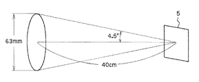
図3は拡散板5が透過型の場合である。透過型拡散板5から40cmの距離でφ63mmの大きさに光線を拡大しようとすると、光線の拡散角は半値幅で4.5°の拡散角を持つことが必要になる。拡散板5表面の微細な凹凸で光線を屈折させる場合、その凹凸の形状をsin波形状と仮定し、拡散面の屈折率を1.5とする。すると、図4に示すように、入射角をθ、屈折角をθ’とし、θ’−θ=4.5°とスネルの式から、入射角θは約8.86°の傾きを持つ必要があることが分かる。つまり、表面荒さの傾きの最大値は8.86°であることが必要である。ここで、面の形状は滑らかなsin波形状としていることから、その形状は、
y=a×sin(2πx/T)
で表される。ここで、aは振幅、Tは周期である。そして、その傾きは、
(傾き)=dy/dx=a×cos(2πx/T)×2π/T
となる。傾きが最大になるのは、x=2πm(mは整数)のときであるから、
(傾きの最大値)=a×2π/T
となり、これが8.86°になるときのa/Tを求めればよいことになる。
【0043】
(傾きの最大値)=a/T×2π=8.86/180×π=0.154
これからa/Tを求めると、
a/T=0.0246
となる。ここで、JIS B0601による算術平均荒さRaとaの関係は、形状が正弦波の場合は、
Ra/√2=a
となり、さらに凹凸の平均間隔Smと上記周期Tの関係は、
Sm=T
となる。これより、表面粗さに関しては以下の結果を得る。
【0044】
Sm=28.7Ra
の場合、拡散面の最大傾斜は8.83°となり、屈折率1.5の場合、光線の拡散半角4.5°、拡散全角で9°の拡散板が得られる。
【0045】
次に、図5は拡散板5が反射型の場合である。反射型拡散板5から40cmの距離でφ63mmの大きさに光線を拡大しようとすると、光線の拡散角は半値幅で4.5°の拡散角を持つことが必要になる。拡散板5表面の微細な凹凸で光線を反射させる場合、その凹凸の形状をsin波形状と仮定すると、図6に示すように、入射角、反射角をθとし、2θ=4.5°から、入射角θは4.5°の半分の約2.25°の傾きを持つ必要があることが分かる。つまり、表面荒さの傾きの最大値は2.25°であることが必要である。ここで、面の形状は滑らかなsin波形状としていることから、その形状は、
y=a×sin(2πx/T)
で表される。そして、その傾きは、
(傾き)=dy/dx=a×cos(2πx/T)×2π/T
となる。傾きが最大になるのは、x=2πm(mは整数)のときであるから、
(傾きの最大値)=a×2π/T
となり、これが2.25°になるときのa/Tを求めればよいことになる。
【0046】
(傾きの最大値)=a/T×2π=2.25/180×π=0.03927これからa/Tを求めると、
a/T=0.00625
となる。ここで、JIS B0601による算術平均荒さRaとaの関係は、形状が正弦波の場合は、
Ra/√2=a
となり、さらに凹凸の平均間隔Smと上記周期Tの関係は、
Sm=T
となる。これより、表面粗さに関しては以下の結果を得る。
【0047】
Sm=113.14Ra
の場合、拡散面の最大傾斜は2.25°となり、反射による拡散半角4.5°、拡散全角で9°の反射型拡散板5が得られる。
【0048】
これを、2回透過型拡散板、裏面鏡型拡散板についても検討すると、Sm/Raと拡散半角との関係は、拡散面の凹凸面をsin波形状に近似できる場合は、図7に示すようになる。
【0049】
以上のような知見から、拡散板5の表面粗さは、以下の条件を満足することが望ましい。
【0050】
5<(Sm/Ra)<1000 ・・・(1)
この条件は、拡散板5に好ましい拡散特性を持たせるために必要な条件であり、拡散特性を表面の微細な凹凸形状により与える場合である。光線を拡散させる方法に、拡散板5表面の微細な凹凸形状を用いると、拡散特性に波長依存性が非常に少なくなり好ましい。また、透過率も他の方法に比べて拡散板5表面でのフレネル反射のみになり、透過率の低下が少ない。さらに、AR(反射防止)コート等を行うことにより、さらに透過率を上げることが可能である。
【0051】
さらに好ましくは、
10<(Sm/Ra)<500 ・・・(1−1)
なる条件を満足することが好ましい。
【0052】
また、本発明の拡散板5の拡散面は、以下条件を満足するようなランダムな凹凸形状にするのがよい。これにより、広い射出瞳径で、ざらつき感のないクリアーで明るい観察像を得ることができる。
【0053】
1回透過型の拡散板では、
5<(Sm/Ra)×(Ep/400)<70 ・・・(2)
2回透過型の拡散板では、
10<(Sm/Ra)×(Ep/400)<80 ・・・(3)
表面反射型の拡散板では、
50<(Sm/Ra)×(Ep/400)<200 ・・・(4)
裏面反射型の拡散板では、
80<(Sm/Ra)×(Ep/400)<250 ・・・(5)
なる条件を満足することが好ましい。ここで、SmはJIS B0601による表面の凹凸の平均間隔(μm)、Raは表面の中心線平均粗さ(μm)、Epは拡散面から観察者の眼の位置までの距離(:アイポイント(mm))である。
【0054】
上記条件式(2)〜(5)の下限を下回ると、拡散角が小さくなりすぎ、広い瞳径を得るとこが難しくなる。また、上限を上回ると、拡散しすぎてしまい観察像が暗くなってしまう。
【0055】
なお、接眼光学系4にフレネルレンズを用いる場合には、拡散面の凹凸形状をランダムな配置にすることがより好ましい。凹凸形状に周期性があると、フレネルレンズのピッチと拡散面との間でモアレ縞が発生して観察像に重畳し、見にくい像となってしまう。
【0056】
上記条件式(2)〜(5)については、それぞれ以下のようにさらに限定することがより望ましい。
【0057】
1回透過型の拡散板では、
10<(Sm/Ra)×(Ep/400)<40 ・・・(2−1)
2回透過型の拡散板では、
15<(Sm/Ra)×(Ep/400)<60 ・・・(3−1)
表面反射型の拡散板では、
70<(Sm/Ra)×(Ep/400)<150 ・・・(4−1)
裏面反射型の拡散板では、
100<(Sm/Ra)×(Ep/400)<200 ・・・(5−1)
さらに好ましくは、拡散板の拡散面の表面の凹凸の平均間隔Smは、
Sm<200μm ・・・(6)
なる条件を満足することが好ましい。この条件(6)は、観察画面のザラザラ感に関係している。拡散面の凹凸が200μm以上だと、特に本発明のように投影光学系2、21 、22 からの光束が細い(NAが小さい)光線で拡散板4近傍に投影像を形成する投影観察装置においては、このSmが映像のザラザラ感(シンチレーション)に大きく影響する。そのため、条件(1)〜(5)を満足しながら、本条件(6)を満足するような拡散面であることが重要である。この条件(6)を満足しないで、Smが200μm以上になると、ひどいときは観察者の眼を移動した場合に画面全体が細かく瞬くように見えるシンチレーションが見えてしまう。また、そこまでひどくなくても、映像がすりガラスに投影された映像のように画像のクリア感がなくなり、鮮やかな映像を観察することができない。
【0058】
さらに好ましくは、
Sm<100μm ・・・(6−1)
なる条件を満足することが好ましい。
【0059】
さらに好ましくは、
Sm<50μm ・・・(6−2)
なる条件を満足することが望ましい。
【0060】
さて、以上のような条件を満足する本発明の拡散板5としては、本出願人による特願2001−370950の作製方法で作製した拡散板が使用可能である。その拡散板としては、以下のものがある。
(1)サンドブラスト法により粒径が制限された球形ビーズを吹き付けて形成されたランダム配置の凹面群あるいはその凹面群に相似的な凹面群、又は、これら凹面群に相補的な凸面群を有する拡散板。
(2)金属基板に球形ビーズを吹き付けて形成されたランダム配置の凹面群を型として透明基板に複製することにより作製された(1)の拡散板。
(3)金属基板上に形成した加工層に球形ビーズを吹き付けて形成されたランダム配置の凹面群を金属基板表面に相似的に転写して形成されたランダム配置の凹面群を型として透明基板に複製することにより作製された(1)の拡散板。
(4)前記球形ビーズの粒径が0.01mmから2mmのガラスビーズからなる(1)から(3)の拡散板。
(5)前記球形ビーズを吹き付ける空気圧が0.5〜3.0kg/cm2 である(4)の拡散板。
(6)前記金属基板が真鍮からなる(2)、(4)、(5)の拡散板。
(7)前記金属基板が前記球形ビーズより硬度の高い金属からなる(3)、(4)、(5)の拡散板。
(8)前記金属基板の表面に形成された凹面群を射出成形あるいはプレス成形により透明基板に複製した(2)〜(7)の拡散板。
(9)基板上に樹脂の液滴を噴霧して付着させることにより形成されたランダム配置の凸面群を基板表面に相似的に転写して形成されたランダム配置の凸面群、又は、その凸面群に相補的な凹面群を有する拡散板。
【0061】
さらに、特許文献5に記載されている拡散板を使うことができる。この拡散板は、透明基体の片面又は両面を粗面化して作製したものである。透明基体の片面又は両面を粗面化する方法としては、例えば以下の(1)〜(4)の方法がある。(1)透明基体の片面又は両面をエッチング処理する方法、(2)樹脂にフィラーを、必要に応じて、水や有機溶剤と共に分散した塗料又はインクをコーティングや印刷を行うことにより、透明基体の片面若しくは両面上に単層又は多層に分けて設ける方法、(3)樹脂やフィラー単体又はこの混合物からなる粉体を静電粉体コーティングや粉体電着コーティングにより、透明基体の片面又は両面に設ける方法、(4)有機又は無機のフィラーを樹脂と共に、熱と圧力を加えることにより溶融し、この溶融物を押し出し成形や射出成形等によりフィルム化して成形する方法。この場合に、この拡散板のHAZE値(JISK7105)が、10〜40の範囲にあることが好ましい。
【0062】
また、特許文献6で作製した拡散板を使うこともできる。この拡散板を作製する方法は、基体上に直接又は他の層を介して結着層を積層する工程と、フィラーを加圧媒体によって結着層に埋め込む工程と、その工程で得た積層体に付着した余剰フィラーを除去する工程とを具備している。
【0063】
接眼光学系4としては、前記したように、フレネルレンズやフレネル反射鏡のようにフレネル面により構成されていることが望ましい。また、接眼光学系4は、偏心フレネル反射面で構成するすることができる。接眼光学系4をフレネルレンズやフレネル反射鏡のようにフレネル面により構成することにより、接眼光学系4を薄く構成できる。その結果、投影観察装置を小型で折り畳みやすいものにすることができるまた、後記の実施例のように凹面鏡1枚から構成されていてもよい
また、接眼光学系4を反射光学系で構成することにより、観察者側に投影された投影光学系2L、2Rや9L、9Rの射出瞳(射出瞳像)における収差の発生が少なくなる。その結果、拡散板5の拡散性を上げなくても、観察視域が広くとれる。また、不要な方向に拡散する光が少なくなる分、照明の光量を増やさずに明るい観察像を観察できる。特に、本発明のように、接眼光学系4の光軸が偏心している光学系においては偏心収差の発生が大きい。しかも、接眼光学系4がシンプルな場合は、この偏心収差を補正する面を他に設けることが難しい。このような点から、元々偏心収差の発生が少ない反射光学系を使うことは好ましいといえる。
【0064】
また、接眼光学系4をフレネル面で構成すると、接眼光学系4を薄くすることが可能である。これは、フレネル面は略平面で構成するとが可能であることによる。また、反射型のフレネル面では、光学作用面である輪帯状の反射面の光軸に垂直な面に対してなす角度が小さくなることにより、フレネルレンズで問題となるフレネル端面(非作用面)でのゴースト光の発生が少なくなる。また、光線の透過効率も高くできる。また、走査手段81 、82 で決まる2つの光軸のなす角度を後記のように大きくとる場合には望ましいものとなる。
【0065】
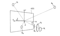
図8に、本発明の第3の投影観察装置の光学系の概念図を示す。本発明の第3の投影観察装置は、複数の観察者が異なる方向から、映像を同時に観察することができる投影観察装置である。図8に示す投影観察装置は、図2と同じように、2つの光源71 、72 と、2つの走査手段81 、82 、及び、2つの投影光学系91 、92 を有する。そして、接眼光学系4と拡散板5の近傍に投影像31 、32 を形成し、異なる観察者M1 、M2 の眼E1 、E2 に見2つの映像が投影されるように構成されている。また、図8では、接眼光学系4で投影された投影光学系91 、92 の射出瞳、すなわち射出瞳像を61 、62 で示している。また、拡散板5で拡大された射出瞳像を601 、602 で示してある。なお、図1のような2つの表示素子と2つの投影光学系を用いる投影観察装置についても、同様に構成できる。
【0066】
接眼光学系4近傍に形成される投影像31 、32 は、図8に示すように少なくとも一部が重なるように形成される。この構成により、接眼光学系4と拡散板5が構成する表示面が小さくても、異なる映像を小さい表示面に表示することが可能となる。
【0067】
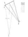
さて、図8の構成では、投影光学系91 、92 を介して走査手段81 、82 から接眼光学系4に至る光軸は接眼光学系4と交差する。そこで、何れか一方の光軸が交差する点における接眼光学系4の垂線とその光軸とのなす角は10°以上であることが望ましい。この点について、図9を用いて説明する。
【0068】
図9に示すように、走査手段81 、82 から投影光学系91 、92 を介して接眼光学系4に至る光軸は、拡散板5と接眼光学系4の略中心を通過して観察者M1 、M2 の眼球位置に到達する。なお、ここでは、拡散板5の拡散作用は考えないとしている。
【0069】
本発明の投影観察装置としては、1つの表示面に形成された映像を、少なくとも2人以上で異なる方向から観察する個人用ディスプレイとしての使用が考えられる。この場合、表示面と観察者の距離は40cm〜1m程度になる。一方、2人以上の観察者、ここでは2人の観察者M1 、M2 は顔を寄せて合って観察することはないので、両者の顔の中心間の距離は40cm以上離れると思われる。この場合、投影光学系91 の光軸と投影光学系92 の光軸とのなす角度は、53°〜22.6°になる。このように、お互いの顔が近づくことによる心理的ファクターを考えると、点Pにおける接眼光学系4の垂線Nと投影光学系91 、92 の光軸(投影光学系91 、92 を介して走査手段81 、82 から接眼光学系4に入射する光軸)の少なくとも何れ一方の光軸とのなす角αは10°以上であることが望ましい。ここで、点Pは、投影光学系91 、92 の光軸の少なくとも何れか一方が、接眼光学系4と交差する点である。また、接眼光学系4の垂線Nとは、接眼光学系4の主面に対する垂線であり、接眼光学系4をフレネルレンズやフレネル反射鏡で構成する場合は、そのレンズや反射鏡に対する垂線となる。
【0070】
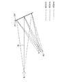
図9は2次元偏心的に走査手段81 、82 と投影光学系91 、92 を配置した場合であるが、3次元偏心的に配置する場合も同様のことが言える。図10は、走査手段81 、82 と投影光学系91 、92 を3次元偏心的に配置したときの模式図である。なお、図10では、一方の走査手段81 と投影光学系91 のみしか図示していない。また、投影光学系91 、92 の射出瞳をそれぞれ161 、162 で示し、それらの接眼光学系4による投影像である射出瞳像を61 、62 で示してある。図10に示すように、投影光学系91 、92 を3次元偏心的に配置する場合も、図9と同様に、点Pにおける垂線Nと投影光学系91 、92 の光軸とのなす角αを、10°以上にすることが望ましい。
【0071】
ところで、本発明の場合も、拡散板5の拡散角は半値全幅で20°以下であることが好ましい。拡散板5に上記条件の拡散特性を持たせることにより、観察者別に各々の投影像31 、32 を観察させることが可能となる。この条件の上限の20°を越えると、投影像31 、32 が異なる映像の場合、異なる映像がダブって見える「クロストーク」が発生する。このため、観察者は、表示内容を正しく観察することができなくなってしまう。また、上限の20°を越えると、拡散角が大きくなりすぎ観察像の明るさが暗くなる。そのため、必要な光量を確保しようとすると、光源71 、72 が大掛かりになってしまう。なお、投影像31 、32 が同一映像の場合、クロストークの問題は生じない。
【0072】
また、拡散板5は、10分の1全幅で拡散角が40°以下となる拡散特性を有することが好ましい。少なくとも40°以上に拡散する光線は観察者に届かない。よって、上記条件を満足することにより、無駄な照明光が減り、照明光の利用効率が向上する。その結果、光源71 、72 として小型で低出力のものを使うことが可能となる。なお、半値全幅から急に拡散光強度が低下する特性であることが好ましい。
【0073】
さらに、拡散板5は、10分の1全幅で拡散角が30°以下となる拡散特性を有することが好ましい。上記条件を満足することが照明の効率的利用につながる。少なくとも30°以上に拡散する光線は観察者にあまり届かないので、上記条件を満足することが照明の効率的利用につながる。なお、半値全幅から急に拡散光強度が低下する特性であることが好ましい。
【0074】
次に、図9、図10に示す構成では、接眼光学系4に対してい斜め方向から走査手段81 、82 で走査された映像を投影する配置となっている。このような配置で、投影光学系91 、92 を回転対称な光学系で構成すると、投影された像はアオリ像となって像歪みを発生する。この像歪みは、図10に示すように、走査手段81 、82 で走査されて形成された表示面と、投影光学系91 、92 の主面と、接眼光学系4の主面とを平行に配置し、投影光学系91 、92 を光軸に垂直にシフトした形態にすることにより補正できる。あるいは、シャイムフルクの法則を満たすようにこの三者を配置することにより、その像歪みを補正することができる。
【0075】
また、このような像歪みは、走査手段81 、82 により形成する像を、その像歪みをキャンセルするように予め歪ませて表示することにより、電気的に補正することもできる。さらに、上記の光学的な補正方法と電気的な補正方法の両方を用いることも可能なことは言うまでもない。
【0076】
また、投影光学系91 、92 としては偏心光学系を使うことが望ましい。その場合、投影光学系91 、92 は回転非対称面を有することが望ましい。なお、回転非対称な曲面形状としては、限定的でないが、自由曲面を用いることが望ましい。自由曲面は、例えば特許文献7(特許文献8)の(a)式により定義される自由曲面であり、その定義式のZ軸が自由曲面の軸となる。
【0077】
また、投影光学系91 、92 の少なくとも1つは、屈折率(n)が1よりも大きい(n>1)媒質で形成された偏心プリズムを1個以上備えた偏心プリズム光学系から構成する。その偏心プリズムは、走査手段あるいは表示素子から射出された光束をプリズム内に入射する入射面と、その光束をプリズム内で反射する少なくとも1つの反射面と、光束をプリズム外に射出する射出面とを有する。そして、その少なくとも1つの反射面が、光束にパワーを与える曲面形状を有し、その曲面形状が偏心によって発生する収差を補正する回転非対称な面形状にて構成されているものとするのが好ましい。これにより、像歪補正能力が格段に向上する。特に、少なくとも2つの投影光学系91 、92 の光軸の相互になす角が30°以上の場合には好ましい。
【0078】
なお、本発明において投影光学系91 、92 として用いる偏心プリズム光学系は、偏心プリズムを1個又は複数個用いてたものでもよい。あるいは、図11に模式的に示すように、回転対称なレンズ系と偏心プリズムを組み合わせたものを用いてもよい。
【0079】
偏心プリズムの1例としては、走査手段81 、82 からの光束をプリズム内に入射させる入射面と、その入射面からプリズム内に入射した光束をプリズム内で反射する第1反射面と、その第1反射面で反射された光束をプリズム内で反射する第2反射面と、その第2反射面で反射された光束をプリズム外に射出する射出面とを備え、その入射面から第1反射面へ向かう光束と第2反射面から射出面へ向かう光束とがプリズム内で交差する面配置を有し、入射面、第1反射面、第2反射面、射出面の少なくとも1面が非回転対称面からなる偏心プリズムがある。
【0080】
このような偏心プリズムを用いると、プリズム内の光路が交差光路になり、反射面(第1反射面と第2反射面)での入射角度が小さくなる。その結果、偏心収差の発生をすくなくすることができる。
【0081】
あるいは、投影光学系91 、92 に用いる偏心プリズムのもう1つの例としては、走査手段81 、82 からの光束をプリズム内に入射させる入射面と、その入射面からプリズム内に入射した光束をプリズム内で反射する第1反射面と、その第1反射面で反射された光束をプリズム内で反射する第2反射面と、その第2反射面で反射された光束をプリズム外に射出する射出面とを備え、その入射面と第2反射面とを1面で兼用した偏心プリズムがある。
【0082】
この第2反射面と入射面とを兼用するタイプの偏心プリズムは、第2反射面で光線を大きく屈曲させ、第1反射面は少ない屈曲角で光線を第2反射面へと反射するために、プリズム光学系の入射光線方向の厚さを薄くすることが可能なものである。
【0083】
さて、以上のように、投影光学系91 、92 を偏心プリズム光学系で構成すると、以下のような利点がある。それは、接眼光学系4に対して斜め方向から走査手段81 、82 で形成された映像を入射させる場合、偏心プリズム光学系を面対称形状に構成することにより、アオリ像の像歪みを補正することが容易になることである。すなわち、この斜め配置により発生する像歪みは、所定の方向から見た時に非対称な形状をしているが、投偏心プリズム光学系によって発生する非対称な像歪みの発生方向と一致する。そのため、偏心プリズム光学系の偏心収差によりその像歪みを補正することが可能となり、収差補正が容易になる。なお、所定の方向とは、投影光学系91 、92 の光軸が接眼光学系4と交差する点をPとし、この点Pを含む偏心プリズム光学系の対称面方向のことである。
【0084】
もちろん、この場合も、このような像歪みは、走査手段81 、82 で形成する像をその像歪みをキャンセルするように予め歪ませて表示することにより、電気的に補正することもできる。さらに、上記の光学的な補正方法と電気的な補正方法の両方を用いることも可能なことは言うまでもない。
【0085】
ところで、このように投影光学系91 、92 を面対称形状の偏心プリズム光学系で構成して用いる場合においても、点Pにおける接眼光学系4の垂線と投影光学系91 、92 の光軸(少なくとも一方)とのなす角を、上記の通り10°以上とする必要がある。
【0086】
次に偏心プリズムと走査手段の好ましい配置を図11を用いて説明する。図11において、点Pは偏心プリズム光学系91 の光軸と接眼光学系4との交点である。偏心プリズム光学系91 は対称面を有し、対称面が点Pを含むように偏心プリズム光学系91 が配置されている。また、偏心プリズム光学系91 の入射面側(物体面側)には、走査手段81 が配置されている。そして、走査手段81 によって映像が接眼光学系4近傍に形成されたたときに、映像を形成する光束が移動する方向、すなわち縦走査方向又は横走査方向が接眼光学系4の縦又は横方向と略一致するように、走査手段81 を光軸の周りで回転させて配置する。偏心プリズム光学系92 と走査手段82 についても同じように配置する。
【0087】
このような走査手段81 、82 の配置により、接眼光学系4に対する投影光学系91 、92 の斜め配置によって発生する回転非対称な像歪みを、面対称形状の偏心プリズム光学系で補正できる。それだけでなく、何れの投影光学系91 、92 の偏心プリズム光学系も、同一形状のものとして用意すれば良い。よって、例えば相互に面対称な形状のように、左右の投影光学系91 、92 を異なる形状に構成する場合に比べて、投影光学系91 、92 の製造コストを大幅に下げることが可能となる。
【0088】
なお、走査手段81 、82 として、特許文献4に示されたような2次元方向に走査するジンバル構造の走査ミラーを用いることができる。この場合には、投影光学系91 、92 は必ずしも用いる必要ない。
【0089】
ところで、以上の図1、図2、図8〜図11の構成の投影観察装置においては、拡散板5として、拡散特性に指向性のある微細な凹凸面又は粗面からなるものを主として想定していたが、拡散板5としてホログラムからなる拡散板をそれぞれの投影観察装置に用いてもよい。ホログラムからなる拡散板としては、透過型ホログラムと反射型ホログラムとが考えられる。ここで、体積型感光材料中に記録されたホログラムの場合、透過型ホログラムは波長選択性が低く、反射型ホログラムは波長選択性が高い。カラー像を表示する投影観察装置に用いる場合には、R(赤色)、G(緑色)、B(青色)3波長の光を拡散させるめに3つのホログラム干渉縞を多重記録する必要があるため、ホログラムとしては波長選択性が比較的低い透過型ホログラムを用いる方が望ましい。そして、投影観察装置を小型に構成するには、接眼光学系として凹面鏡(フレネル凹面反射鏡を含む)を用いてこのような透過型ホログラムからなる拡散板と組み合わせて構成することが望ましい。以下、このような透過型ホログラムからなる拡散板25と凹面鏡24からなる接眼光学系とを用いて構成する投影観察装置について説明するが、以後のこの構成の投影観察装置においては、表示素子、光源、走査手段の図示は省く。しかしながら、図1、図2等と同様に、これらは投影光学系2、9の入射側に配置される。また、以後のこの構成の投影観察装置において、左右あるいは複数の光学系の中、何れか1つだけを示し、他は省略して説明する。
【0090】
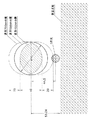
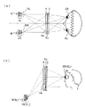
図12(a)に、本発明に基づき構成されたこのような投影観察装置の光学系の概念図を、また、図12(b)に、その投影観察装置の配置例を示す。なお、図12(b)において、凹面鏡24はフレネル凹面反射鏡で構成されている。上記のように、表示素子、光源、走査手段は図示を省かれている。図12(b)では、表示素子に表示された映像、あるいは、それら光源からの光束が走査手段で偏向されて形成された映像は、投影光学系2(9)で拡大投影される。そして、その投影像近傍には透過型ホログラムからなる拡散板25と、接眼光学系とが配置されている。接眼光学系は凹面鏡24からなり、投影光学系2(9)の射出瞳を所定の位置に形成する。この所定の位置は、観察者Mの眼球と略一致している。投影光学系2(9)の接眼光学系24により形成された射出瞳像6は、拡散板25によって観察しやすい大きさの射出瞳像60に拡大される。これにより、観察者Mの眼Eの位置が射出瞳像6の位置から多少ずれても、投影像を観察像として観察することが可能になる。この結果、図1等の場合と同様に、観察しやすい投影観察装置が得られる。
【0091】
ここで、本発明における特徴は、図12(a)に示すように、透過型ホログラムからなる拡散板25は接眼光学系の凹面鏡24の入射側に配置されるため、投影光学系2(9)から装置の射出瞳60の位置に至る光線は、透過型ホログラム25を往復で計2回透過する点にある。このような特徴を有するため、光は透過型ホログラム25で2度回折されることになる。このことを踏まえて、本発明では1回目(凹面鏡24に入射する前)の透過型ホログラム25を透過する角度と、2回目(凹面鏡24に入射した後)の透過型ホログラム25を透過する角度とを積極的に異ならせて、そのホログラムの角度選択性により何れか一方での回折を避けるようにしている。そのための配置については、後記する。
【0092】
そして、透過型ホログラムからなる拡散板25は上記の拡散板5と同様に、その拡散角が、同様の理由で半値全幅で20°以下であることが好ましい。さらに、拡散角は半値全幅で10°以上あるのが好ましい。
【0093】
また、その拡散板25は、10分の1全幅の拡散角が40°以下となる拡散特性を有することが好ましい。さらに、10分の1全幅で拡散角が30°以下となる拡散特性を有することが好ましい。
また、図1、図2の場合のように、立体像を観察する構成の場合は、透過型ホログラムからなる拡散板25の拡散角は半値全幅で8°以下であることが好ましい。また、10分の1全幅の拡散角が12°以下であることが好ましい。
【0094】
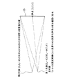
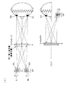
次に、透過型ホログラムからなる拡散板25の屈曲作用と波長分散の関係、接眼光学系の凹面鏡24と透過型ホログラムからなる拡散板25の配置関係について説明する。透過型ホログラムからなる拡散板25は、参照光と拡散光源(2次光源)からの物体光との干渉記録によって作製される。この時、参照光と物体光が同軸(インライン)配置での記録であると、図13(a)に示したように、投影光学系2(9)からの軸上主光線26は、拡散板25に1回目の入射をして拡散板25で屈曲されずに直通する。そして、拡散板25を直通した主光線は、凹面鏡24で反射されて方向を変え、拡散板25を裏面側から入射して拡散板25を直通する。この際、1回目の入射の際に入射光の入射角度が、透過型ホログラム(拡散板25)の再生光入射角度(回折効率がピーク近傍になる角度)を満足していれば、1回目の透過の際に直通する主光線の周りに回折による拡散光が分布し、2回目の透過の際にはその拡散光はほとんど直通する。一方、2回目の入射の際に入射光の入射角度が、再生光入射角度を満足していれば、1回目の透過の際には軸上主光線26は回折されずにほとんど直通し、2回目の透過の際に直通する主光線の周りに回折による拡散光が分布する。いずれの場合も、0次光270 と主光線271 は同じ方向に進む。図13(a)はこの様子を示したものであり、拡散光は図示していない。この図では、拡散板25で回折されない0次光270 と回折された拡散光中の主光線(中心光線)271 のみを図示してあり、0次光270 と主光線271 は同じ方向に進み、装置の射出瞳60の中心に達する。したがって、図13(a)に示すように、透過型ホログラムからなる拡散板25が拡散作用のみで、光路の屈曲作用を持たない場合は、拡散光だけでなく回折により拡散されない0次光270 が射出瞳60に達する。その結果、観察される映像中心に0次光270 のスポットが見えることになり望ましくない。
【0095】
そこで、透過型ホログラムからなる拡散板25として、参照光と物体光が相互に同軸でないオフライン配置の関係で記録したものを用いる。このようなオフライン配置で記録した拡散板25は、再生光入射角度を満足して回折する場合に光線の屈曲と共に波長分散が生じる。その屈曲方向によって図13(b)、(c)のような光路と、図14(a)、(b)のような光路とをとる。ただし、図13(b)、(c)は拡散板25の再生光入射角度条件が1回目の入射の際に満足する場合であり、図14(a)、(b)は2回目の入射の際に満足する場合である。図13(b)、図14(a)は、拡散板25の屈曲方向が法線に対する入射角に対して回折角が小さくなる方向の場合であり、図13(c)、図14(b)は、入射角に対して回折角が大きくなる方向の場合である。各図中、拡散光の図示は省き、拡散板25で回折して屈曲されたR、G、Bの波長の主光線(中心光線)をそれぞれ27R 、27G 、27B で示してある。各図から明らかなように、拡散板25のとして光線の屈曲作用を持つ透過型ホログラムを用いると、ホログラムで回折されない0次光270 を回折光27R 、27G 、27B から分離できる。その結果、装置の射出瞳60に入射しないように構成可能になる。具体的には、装置の射出瞳60の位置で、射出瞳60の中心からその瞳径の2分の1以上離れて0次光270 が入射するように構成することが望ましい。
【0096】
なお、透過型ホログラムでの屈曲角(偏角)を上記入射角と回折角の差の絶対値γで定義し、かつ、その屈曲角をd線(波長587.6nm)で測るとした場合、屈曲角γが小さすぎると、上記のように観察像中に0次光が入射する。逆に、大きすぎると、波長分散が大きくなりすぎて射出瞳60でR、G、Bの3波長が重なる範囲、すなわち色再現性良く観察できる射出瞳範囲が小さくなりすぎてしまう。
【0097】
したがって、透過型ホログラムからなる拡散板25のd線での屈曲角(偏角)γは、
γ>1° ・・・(7)
の関係を満たす必要がある。
【0098】
さらに好ましくは、
γ>2° ・・・(7−1)
なる条件を満足することが好ましい。
【0099】
さらに好ましくは、
γ>10° ・・・(7−2)
なる条件を満足することが望ましい。
【0100】
また、
γ<45° ・・・(8)
の関係を満たす必要がある。
【0101】
さらに好ましくは、
γ<20° ・・・(8−1)
なる条件を満足することが好ましい。
【0102】
上記の条件(7−2)と(8−1)を組み合わせると、次の条件(9)となる。
【0103】
10°<γ<20° ・・・(9)
この条件(9)についてさらに説明する。この条件の下限の10°を下回ると、0次光と表示像を観察可能にする正規観察光との分離が少なくなる。そのため、観察者が僅かに頭を動かすと、0次光が眼に入ってまぶしくなることが多くなる。また、この条件の上限の20°を越えると、透過型ホログラム25による色分散が大きくなり、その結果観察範囲が狭くなってしまう。
【0104】
さらに、Rを700nmの波長の光、Bを400nmの波長の光としたとき、回折光27R と27B の間の回折角の差は、小さい程望ましい。具体的には、18°以下であることが、上記のように色再現性良く観察できる射出瞳範囲が小さくなりすぎないために必要である。また、装置の射出瞳60の位置では、Rを700nmの波長の光、Bを400nmの波長の光としたとき、回折光27R と27B の間の入射位置の差も小さい程望ましい。具体的には、射出瞳60の瞳径の2分の1以下であるように構成することが望ましい。
【0105】
ところで、図13、図14においては、投影光学系2(9)からの軸上主光線26あるいは0次光270 は凹面鏡24に斜め(凹面鏡24の入射位置での法線に対して角度βをなす。)に入射することを考えていた。ここで、軸上主光線26あるいは0次光270 が凹面鏡24に略直角(β≒0°)に入射すると、拡散板25を2度通過した後にホログラムから射出する主光線27R 、27G 、27B は軸上主光線26と略反対方向に向かう。そのため、装置の射出瞳60の位置と投影光学系2(9)が干渉することになる。そこで、凹面鏡24に入射する投影光学系2(9)からの軸上主光線26又はその0次光270 の凹面鏡24への入射角βは、
0°<β<45° ・・・(10)
の関係を満たすことが望ましい。
【0106】
さらに好ましくは、
5°<β<20° ・・・(10−1)
なる条件を満足することが好ましい。
【0107】
この条件(10−1)についてさらに説明する。この条件の下限の5°を上回ると、凹面鏡24の偏心量が小さくなる。そのため、拡散板25で共役再生が起こり、表示像観察に利用可能な光量が低下する。また、この条件の上限の20°を越えると、凹面鏡24の偏心量が大きくなりすぎる。そのため、投影される瞳収差が大きくなり、均一な明るさの像を観察することが困難になってしまう。
【0108】
また、図13、図14においては、投影光学系2(9)からの軸上主光線26が透過型ホログラムからなる拡散板25及びその裏面側の凹面鏡24に入射する位置は、それぞれの略中心で、拡散板25と凹面鏡24の間には偏心はないものとした。その場合、図13、図14から明らかなように、拡散板25を2度通過した投影光(回折光)27R 、27G 、27B は拡散板25に対して角度をなしており、装置の射出瞳60は拡散板25の正面には位置せず斜め方向から投影された映像を見ることになり、観察される像はアオリ像となって像歪みが発生する。そこで、図15(a)〜(c)に示すように、凹面鏡24を拡散板25に対して偏心させて(何れの図も上方へ偏心させている。)、凹面鏡24で反射された主光線27R 、27G 、27B が拡散板25を2度目に通過して拡散板25に対して略直角をなすようにしている。なお、図15(a)〜(c)はそれぞれ図13(a)〜(c)に対応する場合である。
【0109】
なお、投影光学系2(9)からの拡散板25上に斜め方向から投影像を入射させるので、拡散板25上での投影像もアオリ像となって像歪みが発生する。そのため、投影光学系2(9)はこのようなアオリ像の像歪みを補正する機能を持ったものと使用するのが望ましい。
【0110】
また、装置の射出瞳60を拡散板25の正面に位置するようにし、かつ、投影光学系2(9)からの軸上主光線26あるいは0次光270 は凹面鏡24に斜めに入射するようにすることにより、拡散板25に入射する投影光学系2(9)からの投影光がその表面で反射してノイズ光になる表面正反射光を装置の射出瞳60に入射させないようにする効果も得られる。
【0111】
なお、上記の屈曲角(偏角)γと凹面鏡24への入射角βの比γ/βは、
0.01<γ/β<1000 ・・・(11)
の関係を満たすことが望ましい。
【0112】
さらに好ましくは、
0.5<γ/β<2 ・・・(11−1)
なる条件を満足することが好ましい。
【0113】
この条件(11−1)についてさらに説明する。この条件の下限の0.5を下回ると、透過型ホログラム25の屈曲角が小さくなる。そのため、透過型ホログラム25で回折しない0次光が装置の射出瞳60に入射してしまい、観察像にスポットフレアーがのることになる。また、上限の2を越えると、凹面鏡24の偏心量が比較的小さくなる。この場合、透過型ホログラム25に入射した後、凹面鏡24で反射してから、透過型ホログラム25の裏面で極僅かではあるがフレネル反射により反射され、再度凹面鏡24で反射する光線が存在する。そして、その光線が射出瞳60に入射してしまう。この光線もスポットフレアーとして観察されてしまうので、好ましくない。
【0114】
さらに好ましくは、
1<γ/β<1.5 ・・・(11−2)
なる条件を満足することが、スポットフレアーの点でより好ましい。
【0115】
ところで、透過型ホログラムからなる拡散板25を用いる場合は、表示素子1、1L、1Rを照明する光源、あるいは、走査手段8、8L、8R、81 、82 に入射させる光束を発生する光源7、7L、7R、71 、72 は、単色性の高いLEDやLDをRGB3色組み合わせてなる光源を用いることが望ましい。
【0116】
以下に、本発明の投影観察装置の光学系の実施例について説明する。
【0117】
まず、接眼光学系4の実施例について説明する。本発明の投影観察装置に用いる接眼光学系4の実施例は、実施例1ないし実施例3である。また、各実施例の光路図を図16〜図18に示す。各実施例において、光線追跡を面11(物体面)から面12(像面)までの逆光線追跡で行っている。ここで、面11は観察者瞳位置に相当し、面12は投影光学系9L、9R、91 、92 (図2〜図3、図9〜図11)の射出瞳161 、162 (図10)位置に相当する。なお、実際の投影観察装置では、接眼光学系近傍に拡散作用を有する拡散面、又は拡散作用を有する拡散板を配置してある。しかしながら、以下に示す実施例1乃至3においては、拡散板あるいは拡散面はないものとしている。
【0118】
また、各面は接眼光学系4を基準とし、そこからの偏心量で表しており、拡散作用を持つ拡散面は接眼光学系4の面近傍に配置する。
【0119】
画面(接眼光学系)の大きさは、何れも162.56×121.92mmの大きさである。
【0120】
実施例1は、図16に示すように、アナモルフィック反射鏡31を接眼光学系4とて構成した例である。
【0121】
実施例2は、図17に示すように、自由曲面を反射面32として接眼光学系4を構成した例である。
【0122】
実施例3は、図18に示すように、入射面34を平面、裏面35をフレネル反射面としたフレネル裏面反射鏡33で接眼光学系4を構成した例である。
【0123】
なお、以上の実施例1〜3の構成パラメータは後記する。
【0124】
次に、投影光学系9L、9R、91 、92 の実施例について説明する。本発明の投影観察装置に用いる投影光学系の実施例は、実施例4及び実施例5である。また、各実施例の光路図を図19乃至18に示す。実施例4及び5においては、順光線追跡を行っている。すなわち、光源7から走査面40に向かう順に、光線追跡を行っている。偏心の基準座標は、光源7を基準としそこからの偏心量で表してある。走査面40の大きさは、何れも162.56×121.92mmの大きさである。
【0125】
実施例4を図19と図20に示す。図19は、光学系の光源7から走査面40に至る全体のY−Z断面内の光路図である。また、図20は、その主要部のY−Z断面内の光路図である。
【0126】
光源7から出た光線は、照明光学系を構成する凸平正レンズ71を経て略平行光にされ、その光束は直交する2つの軸周りで回動する走査ミラー80に入射する。走査ミラー80で反射されて走査された光束は、投影光学系9を構成する自由曲面からなる偏心反射鏡91と92で順に反射された後、遠方に配置された走査面40上に走査線を形成する。ここで、凸平正レンズ71の第2面は非球面からなる。この実施例の走査ミラー80の直交する2軸(X軸、Y軸)回りの傾き角はX軸回りの傾き角±10.9886°、Y軸回りの傾き角±13.3719°である。
【0127】
実施例5を図21と図22に示す。図21は、光学系の光源7から走査面40に至る全体のY−Z断面内の光路図である。また、図22は、その主要部のY−Z断面内の光路図である。
【0128】
光源7から出た光線は、照明光学系を構成する光源7側に凹面を向けた正メニスカスレンズ72を経て略平行光にされ、その光束は直交する2つの軸周りで回動する走査ミラー80に入射する。走査ミラー80で反射されて走査された光束は、投影光学系9を構成する偏心プリズム90の第1面93からプリズム内に入射する。入射した光束は第2面94で反射し、次いで第3面95で反射して、その反射光はプリズム内で第1面93から第2面94に向かう光路と交差して、第4面96からプリズム外に射出する。そして、遠方に配置された走査面40上に走査線を形成する。ここで、正メニスカスレンズ72の第2面は非球面からなる。また、偏心プリズム90の第2面94、第3面95は自由曲面からなる。この実施例の走査ミラー80の直交する2軸(X軸、Y軸)回りの傾き角はX軸回りの傾き角±1.5924°、Y軸回りの傾き角±0.69452°である。
【0129】
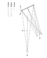
次に、投影光学系2(9)の射出瞳を拡大投影する凹面鏡24と透過型ホログラムからなる拡散板25の組み合わせ光学系の実施例6〜13について説明する。何れの実施例においても、凹面鏡24はフレネル凹面反射鏡24’から構成されている。また、各実施例において、光線追跡は、投影光学系2(9)の射出瞳16を物体面とし、装置の射出瞳(射出瞳16の拡大された射出瞳像)60を像面とし、投影光学系2(9)の射出瞳16の中心から装置の射出瞳60までの順光線追跡で行っている。
【0130】
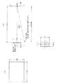
実施例6のY−Z断面内の光路図を図23に示す。また、図24にこの実施例の拡散板25に用いる透過型ホログラムの撮影配置を示す。そして、図25にこの実施例における射出瞳60位置での波長400nm、波長586nm、波長700nmでの射出瞳像の重なり具合と、0次光及び表面反射光の入射位置を示す。なお、図24、図25中の数字はmm単位である。
【0131】
実施例6は、図13(b)に対応して再生光入射角度条件が1回目の入射の際に満足し、2回目には回折せず、かつ、拡散板25の屈曲方向が法線に対する入射角に対して回折角が小さくなる方向の場合の例ある。また、フレネル凹面反射鏡24’はフレネル裏面鏡で構成されており、そのフレネル裏面鏡の偏心量をMY、軸上主光線10の透過型ホログラム25による偏角量をγ、フレネル凹面反射鏡24’への入射角をβとするとすると、
MY=89.27mm
γ=13.15°(屈折率1.49の硝材中で)
β=7.02°(屈折率1.49の硝材中で)
である。
【0132】
また、この実施例の透過型ホログラム25の露光条件は、図24中に示す通り、露光の際の座標系を透過型ホログラム25の面の軸上主光線10の入射点を原点にして、ホログラム面をX−Y面とし、投影光学系2(9)の射出瞳16から離れる方向をZ軸とするとき、露光のための第1光源位置(X1,Y1,Z1)は以下の通りであり、点光源とする。
【0133】
(X1,Y1,Z1)=(0,297.11,−578.12)
また、第2光源位置(X2,Y2,Z2)は以下の通りであり、光源位置を中心にφ82mmの面積を持つ拡散面光源とする。
【0134】
(X2,Y2,Z2)=(0,235.57,−605.67)
以上の露光条件で作製した透過型ホログラムを拡散板25として使用することにより、拡散板25により拡散された光束は、フレネル凹面反射鏡24’で反射された後、観察者瞳面でφ60の拡大瞳60となる。
【0135】
実施例7のY−Z断面内の光路図を図26に示す。また、図27にこの実施例の拡散板25に用いる透過型ホログラムの撮影配置を示す。そして、図28にこの実施例における射出瞳60位置での波長400nm、波長586nm、波長700nmでの射出瞳像の重なり具合と、0次光及び表面反射光の入射位置を示す。なお、図27、図28中の数字はmm単位である。
【0136】
実施例7は、図13(c)に対応して再生光入射角度条件が1回目の入射の際に満足し、2回目には回折せず、かつ、拡散板25の屈曲方向が法線に対する入射角に対して回折角が大きくなる方向の場合の例ある。また、フレネル凹面反射鏡24’はフレネル裏面鏡で構成されており、そのフレネル裏面鏡の偏心量をMY、軸上主光線10の透過型ホログラム25による偏角量をγ、フレネル凹面反射鏡24’への入射角をβとするとすると、
MY=130.46mm
γ=6.61°(屈折率1.49の硝材中で)
β=10.29°(屈折率1.49の硝材中で)
である。
【0137】
また、この実施例の透過型ホログラム25の露光条件は、図27中に示す通り、露光の際の座標系を透過型ホログラム25の面の軸上主光線10の入射点を原点にして、ホログラム面をX−Y面とし、投影光学系2(9)の射出瞳16から離れる方向をZ軸とするとき、露光のための第1光源位置(X1,Y1,Z1)は以下の通りであり、点光源とする。
【0138】
(X1,Y1,Z1)=(0,297.11,−578.12)
また、第2光源位置(X2,Y2,Z2)は以下の通りであり、光源位置を中心にφ82mmの面積を持つ拡散面光源とする。
【0139】
(X2,Y2,Z2)=(0,341.33,−553.14)
以上の露光条件で作製した透過型ホログラムを拡散板25として使用することにより、拡散板25により拡散された光束は、フレネル凹面反射鏡24’で反射された後、観察者瞳面でφ60の拡大瞳60となる。
【0140】
実施例8のY−Z断面内の光路図を図29に示す。また、図30にこの実施例の拡散板25に用いる透過型ホログラムの撮影配置を示す。そして、図31にこの実施例における射出瞳60位置での波長400nm、波長586nm、波長700nmでの射出瞳像の重なり具合と、0次光及び表面反射光の入射位置を示す。なお、図30、図31中の数字はmm単位である。
【0141】
実施例8は、図13(b)に対応して再生光入射角度条件が1回目の入射の際に満足し、2回目には回折せず、かつ、拡散板25の屈曲方向が法線に対する入射角に対して回折角が小さくなる方向の場合の例ある。また、フレネル凹面反射鏡24’はフレネル裏面鏡で構成されており、そのフレネル裏面鏡の偏心量をMY、軸上主光線10の透過型ホログラム25による偏角量をγ、フレネル凹面反射鏡24’への入射角をβとするとすると、
MY=90.64mm
γ=14.28°(屈折率1.62の硝材中で)
β=6.46°(屈折率1.62の硝材中で)
である。
【0142】
また、この実施例の透過型ホログラム25の露光条件は、図30中に示す通り、露光の際の座標系を透過型ホログラム25の面の軸上主光線10の入射点を原点にして、ホログラム面をX−Y面とし、投影光学系2(9)の射出瞳16から離れる方向をZ軸とするとき、露光のための第1光源位置(X1,Y1,Z1)は以下の通りであり、点光源とする。
【0143】
(X1,Y1,Z1)=(0,297.11,−578.12)
また、第2光源位置(X2,Y2,Z2)は以下の通りであり、光源位置を中心にφ82mmの面積を持つ拡散面光源とする。
【0144】
(X2,Y2,Z2)=(0,235.70,−605.76)
以上の露光条件で作製した透過型ホログラムを拡散板25として使用することにより、拡散板25により拡散された光束は、フレネル凹面反射鏡24’で反射された後、観察者瞳面でφ60の拡大瞳60となる。
【0145】
実施例9のY−Z断面内の光路図を図32に示す。また、図33にこの実施例の拡散板25に用いる透過型ホログラムの撮影配置を示す。そして、図34にこの実施例における射出瞳60位置での波長400nm、波長586nm、波長700nmでの射出瞳像の重なり具合と、0次光及び表面反射光の入射位置を示す。なお、図33、図34中の数字はmm単位である。
【0146】
実施例9は、図14(a)に対応して再生光入射角度条件が2回目の入射の際に満足し、1回目には回折せず、かつ、拡散板25の屈曲方向が法線に対する入射角に対して回折角が小さくなる方向の場合の例ある。また、フレネル凹面反射鏡24’はフレネル裏面鏡で構成されており、そのフレネル裏面鏡の偏心量をMY、軸上主光線10の透過型ホログラム25による偏角量をγ、フレネル凹面反射鏡24’への入射角をβとするとすると、
MY=89.27mm
γ=3.76°(屈折率1.49の硝材中で)
β=10.80°屈折率1.49の硝材中で)
である。
【0147】
また、この実施例の透過型ホログラム25の露光条件は、図33中に示す通り、露光の際の座標系を透過型ホログラム25の面の軸上主光線10の入射点を原点にして、ホログラム面をX−Y面とし、投影光学系2(9)の射出瞳16から離れる方向をZ軸とするとき、露光のための第1光源位置(X1,Y1,Z1)は以下の通りであり、点光源とする。
【0148】
(X1,Y1,Z1)=(0,0,−450)
また、第2光源位置(X2,Y2,Z2)は以下の通りであり、光源位置を中心にφ60mmの面積を持つ拡散面光源とする。
【0149】
(X2,Y2,Z2)=(0,−41.73,−424.62)
以上の露光条件で作製した透過型ホログラムを拡散板25として使用することにより、フレネル凹面反射鏡24’で反射された後、拡散板25により拡散された光束は、観察者瞳面でφ60の拡大瞳60となる。
【0150】
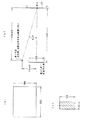
実施例10のY−Z断面内の光路図を図35に示す。また、図36にこの実施例の拡散板25に用いる透過型ホログラムの撮影配置を示す。そして、図37にこの実施例における射出瞳60位置での波長450nm、波長550nm、波長650nmでの射出瞳像の重なり具合と、0次光及び表面反射光の入射位置を示す。なお、図36、図37中の数字はmm単位である。
【0151】
実施例10は、図13(b)に対応して再生光入射角度条件が1回目の入射の際に満足し、2回目には回折せず、かつ、拡散板25の屈曲方向が法線に対する入射角に対して回折角が小さくなる方向の場合の例ある。また、フレネル凹面反射鏡24’はフレネル裏面鏡で構成されており、そのフレネル裏面鏡の偏心量をMY、軸上主光線10の透過型ホログラム25による偏角量をγ、フレネル凹面反射鏡24’への入射角をβとするとすると、
MY=43.23mm
γ=15.00°(屈折率1.4924の硝材中で)
β=3.36°(屈折率1.4924の硝材中で)
である。
【0152】
また、この実施例の透過型ホログラム25の露光条件は、図36(a)中に示す通り、露光の際の座標系を透過型ホログラム25の面の軸上主光線10の入射点を原点にして、ホログラム面をX−Y面とし、投影光学系2(9)の射出瞳16から離れる方向をZ軸とするとき、ホログラムの寸法を、図36(b)に示すように、縦×横を190mm×250mmのものを用い、露光のための第1光源位置(X1,Y1,Z1)は以下の通りであり、点光源とする。
【0153】
(X1,Y1,Z1)=(0,297.11,−578.12)
また、第2光源中心位置(X2,Y2,Z2)は以下の通りであり、図36(c)に示すように、縦×横が144.74mm×86.67mmの面積を持つ拡散面光源とする。
【0154】
(X2,Y2,Z2)=(0,136.36,−635.53)
以上の露光条件で作製した透過型ホログラムを拡散板25として使用することにより、拡散板25により拡散された光束は、フレネル凹面反射鏡24’で反射された後、図37に示すように、観察者瞳面で色再現性良く観察できる射出瞳範囲が縦×横が60mm×60mmの正方形の拡大瞳60となり、その中にφ60の円形瞳が可能になる。この実施例の瞳の色収差(波長450nmの射出瞳像と波長650nmの射出瞳像とのズレ)は40.2mmとなる。
【0155】
なお、本実施例のように、透過型ホログラム25を露光する際に用いる拡散面光源として長方形のものを用い、射出瞳60を正方形のものとすると、観察者が色再現性良く表示像を観察できる範囲が円形瞳の場合より広がるので好ましい。以下の、実施例11〜13の場合も同様。
【0156】
実施例11のY−Z断面内の光路図を図38に示す。また、図39にこの実施例の拡散板25に用いる透過型ホログラムの撮影配置を示す。そして、図40にこの実施例における射出瞳60位置での波長450nm、波長550nm、波長650nmでの射出瞳像の重なり具合と、0次光及び表面反射光の入射位置を示す。なお、図39、図40中の数字はmm単位である。
【0157】
実施例11は、図14(a)に対応して再生光入射角度条件が2回目の入射の際に満足し、1回目には回折せず、かつ、拡散板25の屈曲方向が法線に対する入射角に対して回折角が小さくなる方向の場合の例ある。また、フレネル凹面反射鏡24’はフレネル裏面鏡で構成されており、そのフレネル裏面鏡の偏心量をMY、軸上主光線10の透過型ホログラム25による偏角量をγ、フレネル凹面反射鏡24’への入射角をβとするとすると、
MY=49.77mm
γ=12.30°(屈折率1.4924の硝材中で)
β=12.60°(屈折率1.4924の硝材中で)
である。
【0158】
また、この実施例の透過型ホログラム25の露光条件は、図39(a)中に示す通り、露光の際の座標系を透過型ホログラム25の面の軸上主光線10の入射点を原点にして、ホログラム面をX−Y面とし、投影光学系2(9)の射出瞳16から離れる方向をZ軸とするとき、ホログラムの寸法を、図39(b)に示すように、縦×横を190mm×250mmのものを用い、露光のための第1光源位置(X1,Y1,Z1)は以下の通りであり、点光源とする。
【0159】
(X1,Y1,Z1)=(0,−96.13,−439.65)
また、第2光源中心位置(X2,Y2,Z2)は以下の通りであり、図39(c)に示すように、縦×横が112mm×60mmの面積を持つ拡散面光源とする。
【0160】
(X2,Y2,Z2)=(0,0,−450.00)
以上の露光条件で作製した透過型ホログラムを拡散板25として使用することにより、フレネル凹面反射鏡24’で反射された後、拡散板25により拡散された光束は、図40に示すように、観察者瞳面で色再現性良く観察できる射出瞳範囲が縦×横が60mm×60mmの正方形の拡大瞳60となり、その中にφ60の円形瞳が可能になる。この実施例の瞳の色収差(波長450nmの射出瞳像と波長650nmの射出瞳像とのズレ)は52mmとなる。
【0161】
実施例12のY−Z断面内の光路図を図41に示す。また、図42にこの実施例の拡散板25に用いる透過型ホログラムの撮影配置を示す。そして、図43にこの実施例における射出瞳60位置での波長450nm、波長550nm、波長650nmでの射出瞳像の重なり具合と、0次光及び表面反射光の入射位置を示す。なお、図42、図43中の数字はmm単位である。
【0162】
実施例12は、図13(c)に対応して再生光入射角度条件が1回目の入射の際に満足し、2回目には回折せず、かつ、拡散板25の屈曲方向が法線に対する入射角に対して回折角が大きくなる方向の場合の例ある。また、フレネル凹面反射鏡24’はフレネル裏面鏡で構成されており、そのフレネル裏面鏡の偏心量をMY、軸上主光線10の透過型ホログラム25による偏角量をγ、フレネル凹面反射鏡24’への入射角をβとするとすると、
MY=157.23mm
γ=15.00°(屈折率1.4924の硝材中で)
β=12.57°(屈折率1.4924の硝材中で)
である。
【0163】
また、この実施例の透過型ホログラム25の露光条件は、図42(a)中に示す通り、露光の際の座標系を透過型ホログラム25の面の軸上主光線10の入射点を原点にして、ホログラム面をX−Y面とし、投影光学系2(9)の射出瞳16から離れる方向をZ軸とするとき、ホログラムの寸法を、図42(b)に示すように、縦×横を190mm×250mmのものを用い、露光のための第1光源位置(X1,Y1,Z1)は以下の通りであり、点光源とする。
【0164】
(X1,Y1,Z1)=(0,297.11,−578.12)
また、第2光源中心位置(X2,Y2,Z2)は以下の通りであり、図42(c)に示すように、縦×横が144.44mm×86.67mmの面積を持つ拡散面光源とする。
【0165】
(X2,Y2,Z2)=(0,435.32,−482.72)
以上の露光条件で作製した透過型ホログラムを拡散板25として使用することにより、拡散板25により拡散された光束は、フレネル凹面反射鏡24’で反射された後、図43に示すように、観察者瞳面で色再現性良く観察できる射出瞳範囲が縦×横が60mm×60mmの正方形の拡大瞳60となり、その中にφ60の円形瞳が可能になる。この実施例の瞳の色収差(波長450nmの射出瞳像と波長650nmの射出瞳像とのズレ)は40mmとなる。
【0166】
実施例13のY−Z断面内の光路図を図44に示す。また、図45にこの実施例の拡散板25に用いる透過型ホログラムの撮影配置を示す。そして、図46にこの実施例における射出瞳60位置での波長450nm、波長550nm、波長650nmでの射出瞳像の重なり具合と、0次光及び表面反射光の入射位置を示す。なお、図45、図46中の数字はmm単位である。
【0167】
実施例13は、図14(b)に対応して再生光入射角度条件が2回目の入射の際に満足し、1回目には回折せず、かつ、拡散板25の屈曲方向が法線に対する入射角に対して大きくなる方向の場合の例ある。また、フレネル凹面反射鏡24’はフレネル裏面鏡で構成されており、そのフレネル裏面鏡の偏心量をMY、軸上主光線10の透過型ホログラム25による偏角量をγ、フレネル凹面反射鏡24’への入射角をβとするとすると、
MY=171.54mm
γ=15.00°(屈折率1.4924の硝材中で)
β=2.88°(屈折率1.4924の硝材中で)
である。
【0168】
また、この実施例の透過型ホログラム25の露光条件は、図45(a)中に示す通り、露光の際の座標系を透過型ホログラム25の面の軸上主光線10の入射点を原点にして、ホログラム面をX−Y面とし、投影光学系2(9)の射出瞳16から離れる方向をZ軸とするとき、ホログラムの寸法を、図45(b)に示すように、縦×横を190mm×250mmのものを用い、露光のための第1光源位置(X1,Y1,Z1)は以下の通りであり、点光源とする。
【0169】
(X1,Y1,Z1)=(0,116.62,−434.63)
また、第2光源中心位置(X2,Y2,Z2)は以下の通りであり、図39(c)に示すように、縦×横が128mm×60mmの面積を持つ拡散面光源とする。
【0170】
(X2,Y2,Z2)=(0,0,−450.00)
以上の露光条件で作製した透過型ホログラムを拡散板25として使用することにより、フレネル凹面反射鏡24’で反射された後、拡散板25により拡散された光束は、図46に示すように、観察者瞳面で色再現性良く観察できる射出瞳範囲が縦×横が60mm×60mmの正方形の拡大瞳60となり、その中にφ60の円形瞳が可能になる。この実施例の瞳の色収差(波長450nmの射出瞳像と波長650nmの射出瞳像とのズレ)は68mmとなる。
【0171】
図25、図28、図31、図34から明らかなように、実施例6〜9においては、装置の射出瞳60の位置で、波長700nmの光軸と波長400nmの光軸の入射位置の差が射出瞳の瞳径の2分の1以下であり、RGBの瞳が重なって色再現性良く観察できる射出瞳範囲が広くなっており、その範囲には0次光とホログラムでの表面反射光が入射していないことが分かる。
【0172】
また、図37、図40、図43、図46から明らかなように、実施例10〜13においては、装置の射出瞳60の位置で、波長650nmの光軸と波長650nmの光軸の入射位置の差(色収差)が射出瞳の瞳径の略2分の1以下であり、RGBの瞳が重なって色再現性良く観察できる射出瞳範囲が広くなっており(何れも縦×横が60mm×60mmの正方形の範囲)、その範囲には0次光とホログラムでの表面反射光が入射していないことが分かる。なお、実施例10〜13は、実施例6〜9に比べて、0次光の入射位置が拡大瞳60からより遠くなるように設定した実施例である。
【0173】
以下に、上記実施例1〜13の構成パラメータを示す。上記のように、実施例1〜3においては、軸上主光線10を、物体面11中心を出て絞り面(接眼光学系4の入射面位置に配置されている。)中心を通り像面12の中心に至る光線で定義する。また、実施例4〜5においては、軸上主光線10を、光源7中心を出て光学系の瞳を形成する走査ミラー80中心を通り走査面40に至る光線で定義する。実施例6〜13においては、軸上主光線10を、投影光学系2(9)の射出瞳16の中心を出て透過型ホログラムからなる拡散板25の中心通り装置の射出瞳60中心に至る光線で定義する。
【0174】
そして、実施例1〜3においては、逆光線追跡において、絞り面中心を原点とし、絞り面をX−Y面とし、絞り面に垂直な方向をZ軸方向とし、接眼光学系4の裏面に向かう方向をZ軸正方向としている。実施例4〜5においては、順光線追跡において、光源7の中心を原点とし、軸上主光線10の進行方向をZ軸正方向とし、投影光学系9の偏心面をY−Z面としている。実施例6〜13においては、順光線追跡において、投影光学系2(9)の射出瞳16の中心を原点とし、瞳面をX−Y面とし、瞳に垂直な軸上主光線10の進行方向をZ軸正方向としている。
【0175】
そして、偏心面については、光学系の原点からその面の面頂位置の偏心量(X軸方向、Y軸方向、Z軸方向をそれぞれX,Y,Z)と、その面の中心軸(自由曲面については、前記(a)式のZ軸、非球面については、下記(b)式のZ軸、アナモルフィック面については、下記(c)式のZ軸)のX軸、Y軸、Z軸それぞれを中心とする傾き角(それぞれα,β,γ(°))とが与えられている。その場合、αとβの正はそれぞれの軸の正方向に対して反時計回りを、γの正はZ軸の正方向に対して時計回りを意味する。なお、面の中心軸のα,β,γの回転のさせ方は、面の中心軸とそのXYZ直交座標系を、まずX軸の回りで反時計回りにα回転させ、次に、その回転した面の中心軸を新たな座標系のY軸の回りで反時計回りにβ回転させると共に1度回転した座標系もY軸の回りで反時計回りにβ回転させ、次いで、その2度回転した面の中心軸を新たな座標系の新たな座標系のZ軸の回りで時計回りにγ回転させるものである。
【0176】
また、本発明で用いられる自由曲面の面の形状は、例えば特許文献7(特許文献8)の(a)式により定義される自由曲面であり、その定義式のZ軸が自由曲面の軸となる。
【0177】
また、非球面は、以下の定義式で与えられる回転対称非球面である。
【0178】
ただし、Zを光の進行方向を正とした光軸(軸上主光線)とし、Yを光軸と垂直な方向にとる。ここで、Rは近軸曲率半径、Kは円錐定数、A、B、C、D、…はそれぞれ4次、6次、8次、10次の非球面係数である。この定義式のZ軸が回転対称非球面の軸となる。
【0179】
また、アナモルフィック面の形状は以下の式により定義する。面形状の原点を通り、光学面に垂直な直線がアナモルフィック面の軸となる。
【0180】
ここで、例としてn=4(4次項)を考えると、展開したとき、以下の式(c)で表すことができる。
【0181】
ただし、Zは面形状の原点に対する接平面からのズレ量、CxはX軸方向曲率、CyはY軸方向曲率、KxはX軸方向円錐係数、KyはY軸方向円錐係数、Rnは非球面項回転対称成分、Pnは非球面項回転非対称成分である。なお、X軸方向曲率半径Rx、Y軸方向曲率半径Ryと曲率Cx、Cyとの間には、
Rx=1/Cx,Ry=1/Cy
の関係にある。
【0182】
なお、データの記載されていない自由曲面に関する項は0である。屈折率については、d線(波長587.56nm)に対するものを表記してある。長さの単位はmmである。
【0183】
以下に、上記実施例1〜13の構成パラメータを示す。なお、以下の表中の“FFS”は自由曲面、“ASS”は非球面、“ANM”はアナモルフィック面、“FL”はフレネル面、“RE”は反射面、“SM”は走査ミラー、“HOE”は透過型ホログラム、“PIM”は画像投影面をそれぞれ示す。
【0184】
【0185】
【0186】
【0187】
【0188】
【0189】
【0190】
【0191】
【0192】
【0193】
【0194】
【0195】
【0196】
【0197】
次に、図1の構成の投影観察装置を例にとって、本発明の投影観察装置を立体観察装置として構成する実施例について説明する。
【0198】
図47は、図1に示した構成の投影観察装置を、立体観察装置とした場合の1例を示す図である。ここで、図47(a)は透過型立体観察装置の概略構成図、図47(b)は反射型立体観察装置の概略構成図である。なお、図47(b)では、便宜上右眼用の構成についてのみ示してあり、左眼用の構成は省略してある。
【0199】
図47(a)、(b)に示す立体観察装置は、表示素子1L、1Rと、投影光学系2L、2Rと、接眼光学系4と、拡散板5(図47においては、図示を省略)とを備えて構成されている。
【0200】
投影光学系2L、2Rは、表示素子1L、1Rに表示された映像を観察者側に投影する。この時、投影された映像が同一の表示面に投影するように、光学系が構成されている。接眼光学系4は同一の表示面近傍に配置されている。そして、投影光学系2L、2Rの射出瞳16L、16Rを観察者側に投影する。観察者は投影された射出瞳像の位置に瞳EL、ERを一致させることで、表示素子1L、1Rに表示された映像を観察することができる。拡散板5は、観察用の瞳を拡大する作用を有している。また、接眼光学系4と拡散板5は表示面位置に配置されている。
【0201】
表示面位置は、投影光学系2L、2Rで投影される表示素子1L、1Rの映像の結像位置となっている。そして、この結像位置に配置された接眼光学系4としては、透過型立体観察装置(図47(a))では、フレネルレンズが、反射型立体観察装置(図47(b))ではフレネルミラーが設けられている。
【0202】
フレネルミラー、フレネルレンズは、それぞれ2つの射出瞳16L、16Rの像を観察者側に結像するようになっている。これらのフレネル面は、表示面位置(あるいはその近傍)に配置されているため、投影された映像の画質が劣化しない。また、凹面鏡とは異なり、平板状に配置されている。
【0203】
図48は、上記立体観察装置において、射出瞳像(観察用の瞳)が拡大される原理を示す説明図である。なお、図48では、透過型の立体観察装置の構成を用いている。
【0204】
平面状の表示面位置又はその近傍には、接眼光学系4と共に拡散板5が配置されている。図48において、接眼光学系4は、左右の投影光学系2L、2Rの射出瞳16L、16Rの径φ0をφ0’の大きさで、観察者側の所定の位置に結像する作用を有している。この所定の位置は、観察者の眼球(瞳)瞳EL、ERが位置する所である。ここで、拡散板5は、その拡散作用により、本来φ0’の大きさで結像されるべき6L、6Rの瞳像(左右の投影光学系2L、2Rの射出瞳16L、16Rの像)をφ1の大きさに拡大するようになっている。なお、拡散板5により拡大された左右の射出瞳像60L、60Rは、クロストークの発生を防ぐため距離Lの観察位置では重なり合わないように設定されている。この拡散板5による拡散作用は、透過型立体観察装置では表示面位置に設けられた拡散板5を1回だけ透過するので1回だけ作用し、反射型立体観察装置(図48では不図示)では表示面位置に設けられた拡散光学系を2回透過するため2回作用する。
【0205】
図49は本発明による立体観察装置の1実施例を示す図である。図1(a)は、上方から見た概略構成図、図1(b)は図1(a)の側面図である。本実施例の立体観察装置は、透過型に構成されている。表示面位置には、接眼光学系4が配置されている。接眼光学系4は、投影光学系2L、2Rの射出瞳16L、16Rを、観察者側に投影する。この投影された位置に観察者の眼球(瞳)EL、ERを一致させることにより、観察者は映像の観察が行える。
【0206】
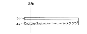
ここで、接眼光学系4としては、観察者側にフレネル面4aを向けたフレネルレンズが用いられている。このフレネルレンズ4の近傍には、瞳拡大のための拡散板5が配置されており、これらで透過型表示パネルを構成している。本実施例では、フレネルレンズ面4aは、投影光学系2L、2Rにより投影された投影像の結像位置に配置されている。このため、フレネルレンズ面4aによる画質の劣化はない。拡散板5の拡散面5aは、フレネルレンズ4のフレネルレンズ面4a側に設けられている。拡散面5aは、フレネルレンズ面4aに近づけて配置されており、ボケを少なくして画質劣化を少なく抑えている。
【0207】
また、本実施例では、透過型表示パネルは、偏心光学系で構成されている。すなわち、フレネルレンズ面4aが偏心フレネルレンズ面となっており、図49(b)に示すように、フレネルレンズ面4aの光軸が中心より下側に位置している。なお、フレネルレンズ面4aは正屈折力を有している。
【0208】
本実施例のように、透過型表示パネルを偏心光学系で構成すると、表示パネル面自体が厚くならずに済む。よって、表示パネルが邪魔にならない配置が可能となる。また、本実施例のように、表示面位置に拡散面5a及びフレネル面4aを極力近づけて配置した方が画質劣化が少ないので好ましい。
【0209】
図50は本発明による立体観察装置の他の実施例を示す説明図である。図50(a)は斜視図、図50(b)は側面図である。
【0210】
本実施例の立体観察装置は反射型に構成されている。そして、表示パネルは、接眼光学系4と瞳拡大のための拡散板5を備えている。接眼光学系4は、具体的にはフレネルミラー4である。接眼光学系4は、投影光学系2L、2Rの射出瞳16L、16Rを、観察者側に投影する。観察者は、この投影位置に瞳EL、ERを一致させることで映像観察ができる。
【0211】
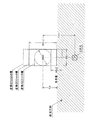
ところで、反射型立体観察装置の場合、投影光学系2L、2Rと観察者の顔とが干渉しないように各光学部材を配置する必要がある。また、観察者は表示パネルを正面から見た方が観察しやすい。そこで、本実施例では、表示パネルの中心へ入射する投影光の入射光軸と表示パネルの中心から出射する光線の出射光軸との間に角度θを持たせている。また、表示パネルの中心に対し、フレネルミラー4の光軸を上下方向(図50においては上方向)に偏心させている。
【0212】
図51は、図50の実施例をより具体化した例を示す側面図である。図51の実施例では、投影光学系2R(2L)に球面レンズ系を用いると共に、表示素子1R(1L)をレンズの光軸から偏心させた位置に配置している。このようにすることで、投影光学系2R(2L)と観察者の顔とが干渉しないようにしている。表示パネルは、観察者の眼及び投影光学系2R(2L)に対して垂直に配置されている。また、表示パネル面には非球面のフレネルミラーが用いられている。
【0213】
なお、上述のように、観察者が表示パネルを正面視する構成とした方が好ましいが、本実施例では、表示パネルは±30°傾けた位置からでも使用可能である。±15°程度の傾斜であれば、良好な映像が観察できるようになっている。
【0214】
図52は図51の実施例の変形例を示す図で、側方から見た概略構成図である。図52において、観察者の視線は水平方向に固定して示してある。本実施例では、表示パネルと観察者眼球(瞳)ER(EL)の位置関係が、次の2つの量で決まる。(1) 表示パネル面の傾斜角度。(2) 表示パネル面に設けられた偏心フレネルレンズ面の光軸の偏心量。これら2つの量を組み合せて調整することにより、最適な状態で観察できるようになっている。なお、投影光学系2R(2L)は、表示パネル面に対して垂直に配置されている。なお、図52中、符号17は支持アームであり、支持アーム17は2つの投影光学系2R(2L)と表示素子1R(1L)と表示パネルとを支持している。また、表示パネル面の傾斜角度αは、表示パネルの中心と観察者の瞳とを結ぶ線と表示パネルの中心からの垂線とのなす角度であり、±30°以下にするのが見やすさの点から好ましい。
【0215】
図52(a)の立体観察装置は、表示パネル面の傾斜角度αが0°になっている。また、図52(b)、(c)の立体観察装置は、表示パネル面の傾斜角度αが30°以下になっている。なお、図52の実施例においては、(c)の構成に比べてて(a)又は(b)の構成の方が、見やすさの自然な点と結像作用の偏心量が少ない点でより有利である。
【0216】
次に、本発明の立体観察装置に用いる表示パネルの具体的な構成例を説明する。
【0217】
図53は、本発明の反射型立体観察装置に適用可能な反射型表示パネルの実施例を示す図である。ここで、図53(a)は斜視図、図53(b)は側方からみた概略構成図である。本実施例の表示パネルは、フレネル面4aと、ランダムに凹面が配置された拡散面5aとを一体形成して構成されている。具体的には、例えば、フレネル面用の金型と散乱面用のランダム配置された凹面の金型とで、ポリカーボネイトやアクリルなどのプラスチック樹脂を両側からプレスして一体成形する。その後、フレネル面4aに反射膜としてアルミをコートし、さらにその上に防護膜として黒色塗料を付ける。
【0218】
表示パネルのフレネル面4aは、2つの投影光学系2L、2Rの射出瞳16L、16Rの像を結像する作用を有する。よって、観察者がこの結像位置に眼球(瞳)を一致させることで映像を観察することができる。また、拡散面5aが観察用の瞳を拡大する作用を有している。よって、観察者は、結像位置から眼球(瞳)を多少ずらしても。一致している状態と同じように映像を観察するすることができる。
【0219】
なお、図53に示す本実施例の表示パネルは、偏心フレネル裏面鏡として構成されている。ここで、表面鏡と裏面鏡とのフレネル面4aの曲率半径Rについて考える。
【0220】
裏面鏡として構成した場合の曲率半径Rは、
R=2n・f
表面鏡として構成した場合の曲率半径Rは、
R=2f
となる。ただし、nは屈折率、fは焦点距離である。
【0221】
このように、裏面鏡で構成した方がフレネル面の曲率半径Rを大きくとることができるので、瞳結像時の収差の発生が少なく有利である。
【0222】
さらに、本実施例の表示パネルでは、フレネル面4aが周辺程曲率半径が大きくなるような非球面フレネル面に構成されている。このように構成すると、観察用の瞳が結像時に発生する収差を非球面でさらに少なく抑えることができ、有利となる。
【0223】
図54は、反射型表示パネルの他の実施例を示す図である。ここで、図54(a)は側方からみた概略構成図、図54(b)は拡散手段の拡大図である。本実施例の表示パネルは、図53に示すようなランダムに凹面が配置された拡散面5aに代わって、図54(b)に示すように、拡散手段としてフレネル面4aに微小な凹面5bを一体形成して構成されている。なお、フレネル面4aには反射膜がコートされており、裏面フレネル反射鏡として構成されている。また、本実施例では、表示パネルの表面は平面であり、反射防止膜が容易にコーティングできるようになっている。
【0224】
このように、本実施例の反射型表示パネルによれば、結像作用をなすフレネル面4aと拡散作用をなす微小な凹面5bとが同一の裏面に形成されている。そのため、図53に示すような反射型表示パネルでは通常2回拡散面を通るのに対し、本実施例では投影光が1回だけしか拡散面を通過しないので、拡散作用は1回しか受けない。その結果、その分だけボケが生じ難く画質劣化を少なく抑えることができる。
【0225】
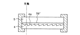
図55は、反射型表示パネルの他の実施例を示す図で、側方から見た概略構成図である。本実施例の表示パネルは、接眼光学系4をフレネル表面鏡で構成すると共に、拡散手段を拡散板5で構成している。そして、フレネル面4aと拡散板5の表面に形成された拡散性を有する凹凸面5b’とが対面し、近接配置されている。
【0226】
本実施例の表示パネルによれば、フレネルミラー面4aが表面に形成されており、拡散性を有する凹凸面5b’と極力密着させることができる。そのため、拡散面を2回通過することにより生じるボケを極力少なく抑えることができる。なお、本実施例の表示パネルは、表面フレネルミラー4と拡散板5とを密着させる構成の他に、拡散板の代わりに拡散性フィルムを表面フレネルミラーに張り合わせて構成してもよい。
【0227】
図56は、反射型表示パネルの他の実施例を示す図であって、側方からみた概略構成図である。本実施例の表示パネルは、図53の実施例で示した偏心フレネル裏面鏡の表面に微小な凹凸面を形成する代わりに、拡散性フィルム5cを貼り合わせて構成されている。なお、拡散性フィルム5cは、内部散乱式のもの、表面に形成された凹凸で散乱させる方式のものの何れのものを用いてもよい。
【0228】
次に、特に本発明の投影観察装置において用いる接眼光学系を凹面鏡、フレネルフレネル反射鏡等の反射型のものを用い、その前面に配置する拡散板として、凹凸面又は粗面からなるもの、あるいは、透過型ホログラムからなるものを用いた表示パネルに、図1あるいは図2のような配置で映像を投影して表示する場合の本発明の投影観察装置の種々の形態について例示する。以下の説明において、反射型の接眼光学系と拡散板との組み合わせを表示パネル100とする。また、投影装置101、101L、101Rは、図1のように、表示素子1とその表示素子1に表示された映像を拡大投影する投影光学系2とからなるもの、あるいは、図2のように、光源7から入射された光束を偏向する走査手段8と、偏向された光束を投影集光する投影光学系9とからなるものとする。
【0229】
図57は、上述の各実施例で示した構成を備えた本発明が適用可能な立体観察システムの実施例を示す概略構成図である。本実施例では、左右の投影装置101L、101Rは投影装置制御装置102に接続されている。投影装置制御装置102は、立体(3D)内視鏡や、立体(3D)顕微鏡等の立体(3D)画像入力装置に設けられている左右のカメラで撮像された画像を選択入力して、左右の投影装置101L、101Rにその選択した画像を送って表示させるように構成されている。また、本実施例では、投影装置制御装置102は、その他の選択入力可能な画像として、パソコンを介して作成された視差を有する立体(3D)画像も本実施例の表示パネル100への入力画像として入力して投影装置101L、101Rに表示させることができるように構成されている。
【0230】
次に、このように構成された本発明による立体観察システムを応用した製品の実施例について説明する。
【0231】
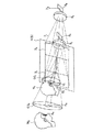
図58は、本発明による立体観察システムを応用した製品の1実施例を示す説明図である。本実施例の製品は、表示パネル100と左右の投影装置101L、101Rとを保持部材103に一体的に取り付けた反射型立体投影観察装置と、保持部103を支持する支持アーム104と、支持アーム104を支持するキャスター付き支持部本体105とで構成されている。反射型立体投影観察装置は、左右の投影装置101L、101Rから互いに視差のある映像を表示パネル100に投影し、表示パネル100で反射して観察者の左右の眼EL、ERにそれぞれ観察用の瞳を拡大させて映像を結像するように構成されている。
【0232】
保持部材103は支持アーム104との連結部104aを介して矢印方向に回動可能に連結されており、支持アーム104は支持部本体105に連結部104bを介して矢印方向に回動可能に連結されており、保持部材103、支持アーム104を所望方向に回動させることで、観察者の観察姿勢を変えることができるようになっている。また、保持部材103には操作部103aが設けられており、所望方向への回動がしやすくなっている。
【0233】
また、支持部本体105はキャスター105aが付いており、支持部本体105を移動させることで観察位置を変えることができようになっている。
【0234】
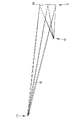
図59は、本発明による立体観察システムを応用した製品の他の実施例を示す説明図である。この実施例の製品は図58と同様の保持部材103に取り付けられた反射型立体投影観察装置を支持する支持アーム104を支持する支持部本体105を天井106に取り付けて構成されている。本実施例のように構成すれば、立体投影観察装置を置くスペースを省略することができる。
【0235】
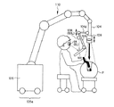
図60は、本発明による立体観察システムを応用した製品の他の実施例を示す説明図である。本実施例の製品は、支持アーム104を手術用の椅子107に取り付けて構成されている。表示パネル100は保持部材103bに取り付けられ、投影装置101L、101Rは保持部材103cに取り付けられている。そして、保持部材103bは、保持部材103cに回動可能に取り付けらており、表示パネル100の投影装置101L、101Rに対する向きを所定の方向に変えることができるようになっている。投影装置101L、101Rを取り付けた保持部材103cは、支持アーム104に連結部104cを介して360°回動可能に取り付けられており、表示パネル100及び投影装置101L、101Rの向きを所定方向に変えることができるようになっている。さらに、表不パネル100の左右側方には取っ手108が設けられており、表示パネル100に直接手を触れずに向きの調整操作がしやすくなっている。また、手術用の椅子107にはキャスター107aが設けられており、手術用椅子107を移動させることで観察位置を変えることができようになっている。
【0236】
図61は、本発明による立体観察システムを応用した製品の他の実施例を示す説明図である。本実施例の製品は、キャスター105a付き支持部本体105及び連結部104cを介して回動可能な支持アーム104を備えた手術用顧微鏡の画像入力部109に、投影装置101L、101Rと表示パネル100とが保持部材103に取り付けられた2台の立体投影観察装置を保持部材103を介して取り付けて構成されている。手術用顕微鏡の画像入力部109には2台のカメラが内蔵され、入力画像はそれぞれの立体投影観察装置の投影装置101L、101Rに送られるように構成されており、手術用顕微鏡での立体画像が複数の観察者に同時に観察できるようになっている。
【0237】
そして、図58〜図61に示した実施例の製品の立体観察システムは、手術用顕微鏡の表示装置、内視鏡の表示装置、医療関連の立体情報画像の表示装置、コンピュータを用いたゲーム機等の娯楽製品の表示装置、各種立体(3D)のCAD画像等の業務関連の立体(3D)画像の表示装置等に適用可能である。
【0238】
図62は、本発明の投影観察装置を用いた手術用立体観察システムの1実施例を示す説明図である。本実施例の製品は、キャスター105a付き支持部本体105に自在アーム110を介して3次元方向に移動自在で360°回転自在に支持アーム104が取り付けられ、その支持アーム104に連結部104dを介して同様に移動自在、回転自在に保持部材103が取り付けられ、その保持部材103に投影装置101L、101Rと表示パネル100とが取り付けられている。一方、支持アーム104先端には、手術用顕微鏡の画像入力部109が取り付けられ、その画像入力部109には2台のカメラが内蔵され、入力画像は立体投影観察装置の投影装置101L、101Rに送られるように構成されており、手術用顕微鏡で患者Pの患部の立体画像を観察しながら手術を行うことができるようになっている。
【0239】
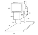
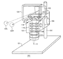
また、以上のような本発明の投影観察装置は、例えば図63に外観を、図64に光学系を透視図として示すような双眼実体顕微鏡として構成することができる。この例の場合、双眼実体顕微鏡130はステージ131に鏡柱132が立っており、その鏡柱132に鏡筒ボックス133が取り付けられている。鏡筒ボックス133は焦点合わせ用ねじ136によってステージ131からの高さが調整可能になっている。鏡筒ボックス133の下端には対物光学系鏡筒134が、その上端にはフード135が取り付けられている。そして、図64から明らかなように、これらの対物光学系鏡筒134、鏡筒ボックス133、フード135内には、対物光学系111、左右の結像光学系114L、114R、合計4枚の平面鏡からなる光路入れ替え作用と光路間隔拡大作用を持つ光学素子118、左右の投影光学系2L、2R、光軸を折り曲げるためのミラー116が配置されており、左右の投影光学系2L、2Rにより、物体Oの左眼用の拡大像と右眼用の拡大像とが表示パネル100上に拡大投影され、また、表示パネル100により拡大された左右の射出瞳60L、60Rが左右の眼のアイポイントとして形成される。この結果、物体Oは観察者の両眼により実体像(立体像)として拡大観察できるものとなる。
【0240】
また、上記のような本発明による反射型の接眼光学系と拡散板との組み合わせからなる反射型の表示パネル100は、立体画像の表示のみならず、単一画像を表示する投影観察装置としても利用可能である。そのような投影観察装置としての携帯電話の例を図65、図66に示す。図65、図66は携帯電話138に操作者自身や通話相手等の撮影像と電話番号等の情報を投影表示する本発明の投影観察装置を備え、そのために投影投影装置101と反射型の表示パネル100を設けてその射出瞳60の位置でその表示映像を無理なく観察できるようにしている。この携帯電話138には、操作者の声を情報として入力するマイク部139と、通話相手の声を出力するスピーカ部140と、通信電波の送信と受信を行うアンテナ141と、操作者が情報を入力する操作ボタン142と、上記の投影観察装置とが設けられている。図15は、表示パネル100を携帯電話138に対して開閉する機構を持っており、携帯時は折り畳んでポケット等に収納することが可能となる。また、図16は、表示パネル100は携帯電話138の本体内部に固定され、折り畳まずにそのままポケット等に収納するものである。
【0241】
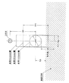
ところで、本発明の投影観察装置の接眼光学系4としてフレネルレンズやフレネル反射鏡を用いるとき、ゴースト光に注意しなければならない。ゴースト光はフレネルレンズの輪帯状の屈折作用面間にある非作用面、あるいはフレネル反射鏡の輪帯状の反射作用間にある非作用面で周囲の光等が反射されることにより生じる。このゴースト光は射出瞳60L、60R、601 、602 に入射して観察の邪魔になる。図67に示すように、非作用面43は、フレネルレンズ41のフレネル面を構成する輪帯状の屈折作用面42間に位置している。そこで、この非作用面43に、例えばガラスビーズ55をフレネルレンズ41の中心方向から斜めに吹き付けて擦り面にする。このようにすることで、本来この面で反射されてゴースト光▲2▼となる光を拡散させることができる。このようにしてゴースト光を防止するようにすることが望ましい。さらには、この擦り面に黒色塗料等を塗布して光吸収性にするとより望ましい。なお、図67中、▲1▼は正規の屈折光を示す。
【0242】
なお、図67に示した例では、フレネルレンズ41に直接ガラスビーズ55等を吹き付けて非作用面を擦り面にする方法であったが、これ以外の方法もある。例えば、図68に示すように、フレネルレンズ41を作成する型51において、非作用面43に対応する面53に、図67と同様にガラスビーズ55等を斜めに吹き付けて擦り面にする方法がある。そして、その擦り面をフレネルレンズ41転写するようにしてもよい。図68中、符号52の面はフレネルレンズ41の輪帯状の屈折作用面42に対応する面である。接眼光学系4をフレネル反射鏡で構成する場合も上記と同様にすることが望ましい。
【0243】
さて、本発明の実施例で使用する拡散板は、特願2001−370950の作製方法に基づき、以下のようにして作製した。まず、サンドブラスト法により粒径が制限された球形ビーズを、型となる金属板に吹き付けた。次に、この金属板に形成されたランダム配置の凹面群を透明樹脂板に転写し複製した。このようにして、透明樹脂板の1面にランダムな凹凸形状が形成された1回透過型拡散板を作製した。サンプルは11個作製した。それぞれのサンプル番号を#1〜#11としたとき、これら#1〜#11の拡散板の拡散光の角度分布は図69のようになった。#1〜#11の拡散板のSm/Raの値、その拡散角の半値全幅、10分の1全幅は次の通りである。この結果から、上記実施例の拡散板5としては、#11の拡散板を使用することが望ましい。
【0244】
サンプル Sm/Ra 拡散角半値全幅 拡散角10分の1全幅
#1 316.67 0.096 0.858
#2 206.25 0.104 0.980
#3 205.88 0.114 1.164
#4 163.64 0.144 1.510
#5 177.78 0.230 2.236
#6 223.53 0.108 1.062
#7 172.00 0.148 1.572
#8 174.07 0.156 1.632
#9 165.52 0.286 2.572
#10 160.61 1.368 3.470
#11 138.46 2.470 5.040 。
【0245】
以上の本発明の投影観察装置は例えば次のように構成することができる。
【0246】
〔1〕 映像を表示する表示素子と、前記表示素子に表示された映像を拡大投影する投影光学系と、前記投影光学系で投影された像近傍に配置された拡散板と、前記投影光学系の射出瞳を観察者側に投影する接眼光学系とを備えており、前記拡散板の拡散角は、半値全幅で20°以下であることを特徴とする投影観察装置。
【0247】
〔2〕 光源からの光束を偏向する走査手段と、前記走査手段からの光を所定の位置に集光する投影光学系と、前記所定の位置近傍に配置された拡散板と、前記投影光学系の射出瞳を観察者側に投影する接眼光学系とを備えており、前記拡散板の拡散角は、半値全幅で20°以下であることを特徴とする投影観察装置。
【0248】
〔3〕 前記拡散板が、光強度が1/10になる半値全幅で拡散角が全幅で40°以下であることを特徴とする上記1又は2記載の投影観察装置。
【0249】
〔4〕 前記拡散板の表面粗さは、以下の条件を満足することを特徴とする上記1から3の何れか1項記載の投影観察装置。
【0250】
5<(Sm/Ra)<1000 ・・・(1)
ただし、SmはJIS B0601による表面の凹凸の平均間隔(μm)、Raは表面の中心線平均粗さ(μm)である。
【0251】
〔5〕 以下の条件を満足することを特徴とする上記4記載の投影観察装置。
【0252】
1回透過型の拡散板では、
5<(Sm/Ra)×(Ep/400)<70 ・・・(2)
2回透過型の拡散板では、
10<(Sm/Ra)×(Ep/400)<80 ・・・(3)
表面反射型の拡散板では、
50<(Sm/Ra)×(Ep/400)<200 ・・・(4)
裏面反射型の拡散板では、
80<(Sm/Ra)×(Ep/400)<250 ・・・(5)
ただし、SmはJIS B0601による表面の凹凸の平均間隔(μm)、Raは表面の中心線平均粗さ(μm)、Epは拡散板の拡散面から観察者の眼の位置までの距離(mm)である。
【0253】
〔6〕 以下の条件を満足することを特徴とする上記4又は5記載の投影観察装置。
【0254】
Sm<200μm ・・・(6)
〔7〕 光源からの光束を偏向する少なくとも2つの走査手段と、前記走査手段各々からの光を所定の位置に集光する少なくとも2つの投影光学系と、前記所定の位置近傍に配置された拡散板と、前記投影光学系各々の射出瞳を観察者側に投影する共通の接眼光学系とを備えており、前記投影光学系の光軸の何れか一方が前記接眼光学系と交差し、交差する点における前記接眼光学系の垂線とその光軸とのなす角が10°以上であることを特徴とする投影観察装置。
【0255】
〔8〕 光源からの光束を偏向する少なくとも2つの走査手段と、前記走査手段各々からの光を所定の位置に集光する少なくとも2つの投影光学系と、前記所定の位置近傍に配置された透過型ホログラムからなる拡散板と、前記投影光学系各々の射出瞳を観察者側に投影する共通の凹面鏡からなる接眼光学系とを備えており、前記投影光学系の光軸の何れか一方が前記接眼光学系と交差し、交差する点における前記接眼光学系の垂線とその光軸とのなす角が10°以上であることを特徴とする投影観察装置。
【0256】
〔9〕 前記投影光学系の少なくとも1つは、屈折率(n)が1よりも大きい(n>1)媒質で形成された偏心プリズムを1個以上備えた偏心プリズム光学系からなり、前記偏心プリズムは、前記走査手段で走査された光束をプリズム内に入射する入射面と、その光束をプリズム内で反射する少なくとも1つの反射面と、光束をプリズム外に射出する射出面とを有し、その少なくとも1つの反射面が、光束にパワーを与える曲面形状を有し、その曲面形状が偏心によって発生する収差を補正する回転非対称な面形状にて構成され、かつ、前記偏心プリズム光学系は面対称形状に構成され、その投影光学系の光軸が前記接眼光学系と交差する点における前記接眼光学系の垂線とその光軸がなす角が10°以上であり、前記交差する点を略含むように前記偏心プリズム光学系の対称面が配置され、前記偏心プリズム光学系に対応する前記走査手段で形成される表示画面の縦又は横方向が前記接眼光学系近傍に投影されたときに、前記接眼光学系の縦又は横方向と略一致するように、前記偏心プリズム光学系の物体面に前記走査手段が配置されていることを特徴とする上記7又は8記載の投影観察装置。
【0257】
〔10〕 前記偏心プリズムの少なくとも1つが、前記走査手段からの光束をプリズム内に入射させる入射面と、その入射面からプリズム内に入射した光束をプリズム内で反射する第1反射面と、その第1反射面で反射された光束をプリズム内で反射する第2反射面と、その第2反射面で反射された光束をプリズム外に射出する射出面とを備え、その入射面から第1反射面へ向かう光束と第2反射面から射出面へ向かう光束とがプリズム内で交差する面配置の偏心プリズムからなることを特徴とする上記9記載の投影観察装置。
【0258】
〔11〕 前記偏心プリズムの少なくとも1つが、前記走査手段からの光束をプリズム内に入射させる入射面と、その入射面からプリズム内に入射した光束をプリズム内で反射する第1反射面と、その第1反射面で反射された光束をプリズム内で反射する第2反射面と、その第2反射面で反射された光束をプリズム外に射出する射出面とを備え、その入射面と第2反射面とを1面で兼用した偏心プリズムからなることを特徴とする上記9記載の投影観察装置。
【0259】
〔12〕 前記走査手段により形成される像を前記投影光学系による像歪みを補償するように歪ませて表示するように構成されていることを特徴とする上記2から11の何れか1項記載の投影観察装置。
【0260】
〔13〕 前記接眼光学系がフレネルレンズからなることを特徴とする上記1から7、9〜12何れか1項記載の投影観察装置。
【0261】
〔14〕 前記接眼光学系が反射面からなることを特徴とする上記1から7、9〜12の何れか1項記載の投影観察装置。
【0262】
〔15〕 前記接眼光学系がフレネル反射鏡からなることを特徴とする上記14記載の投影観察装置。
【0263】
〔16〕 前記接眼光学系がフレネル裏面反射鏡からなることを特徴とする上記14記載の投影観察装置。
【0264】
〔17〕 前記拡散面が前記接眼光学系の少なくとも1面に設けられていることを特徴とする上記12から16の何れか1項記載の投影観察装置。
【0265】
〔18〕 映像を表示する表示素子と、前記表示素子に表示された映像を拡大投影する投影光学系と、前記投影光学系で投影された像近傍に配置された透過型ホログラムからなる拡散板と、前記投影光学系の射出瞳を観察者側に投影する凹面鏡とを備えており、前記透過型ホログラムからなる拡散板の拡散角は、半値全幅で20°以下であることを特徴とする投影観察装置。
【0266】
〔19〕 映像を表示する少なくとも2つの表示素子と、前記表示素子各々からの光を所定の位置に集光する少なくとも2つの投影光学系とを備えていることを特徴とする上記18記載の投影観察装置。
【0267】
〔20〕 光源からの光束を偏向する走査手段と、前記走査手段からの光を所定の位置に集光する投影光学系と、前記所定の位置近傍に配置された透過型ホログラムからなる拡散板と、前記投影光学系の射出瞳を観察者側に投影する凹面鏡とを備えており、前記透過型ホログラムからなる拡散板の拡散角は、半値全幅で20°以下であることを特徴とする投影観察装置。
【0268】
〔21〕 光源からの光束を偏向する少なくとも2つの走査手段と、前記走査手段各々からの光を所定の位置に集光する少なくとも2つの投影光学系とを備えていることを特徴とする上記20記載の投影観察装置。
【0269】
〔22〕 前記凹面鏡がフレネル凹面反射鏡からなることを特徴とする上記8、18〜21の何れか1項記載の投影観察装置。
【0270】
〔23〕 前記投影光学系から装置の射出瞳に至る光線が前記透過型ホログラムからなる拡散板を2回透過する配置において、1回目に前記透過型ホログラムからなる拡散板を透過する角度と、2回目に前記透過型ホログラムからなる拡散板を透過する角度とが異なるように配置されていることを特徴とする上記8、18〜22の何れか1項記載の投影観察装置。
【0271】
〔24〕 前記透過型ホログラムからなる拡散板が、光強度が1/10になる半値全幅で拡散角が全幅で40°以下であることを特徴とする上記8、18〜23の何れか1項記載の投影観察装置。
【0272】
〔25〕 前記透過型ホログラムからなる拡散板の拡散角は、半値全幅で8°以下であることを特徴とする上記19又は21記載の投影観察装置。
【0273】
〔26〕 前記透過型ホログラムからなる拡散板が、光強度が1/10になる半値全幅で拡散角が全幅で12°以下であることを特徴とする上記19又は21記載の投影観察装置。
【0274】
〔27〕 前記投影光学系からの軸上主光線が前記凹面鏡に斜めに入射するように配置されていることを特徴とする上記8、18〜26の何れか1項記載の投影観察装置。
【0275】
〔28〕 前記透過型ホログラムの1回目及び2回目透過時に回折されてない0次光が装置の射出瞳に入射しないように構成されていることを特徴とする上記8、18〜27の何れか1項記載の投影観察装置。
【0276】
〔29〕 装置の射出瞳の位置で、前記透過型ホログラムの1回目及び2回目透過時に回折されてない0次光がその射出瞳の中心からその瞳径の2分の1以上離れて入射するように構成されていることを特徴とする上記8、18〜28の何れか1項記載の投影観察装置。
【0277】
〔30〕 前記透過型ホログラムからなる拡散板が、回折による屈曲作用を有することを特徴とする上記8、18〜27の何れか1項記載の投影観察装置。
【0278】
〔31〕 前記透過型ホログラムからなる拡散板によるd線の光軸の屈曲角をγとするとき、
γ>1° ・・・(7)
の条件を満足することを特徴とする上記30記載の投影観察装置。
【0279】
〔32〕 前記透過型ホログラムからなる拡散板によるd線の光軸の屈曲角をγとするとき、
γ<45° ・・・(8)
の条件を満足することを特徴とする上記30又は31記載の投影観察装置。
【0280】
〔33〕 前記透過型ホログラムからなる拡散板によるd線の光軸の屈曲角をγとするとき、
10°<γ<20° ・・・(9)
なる条件を満足することを特徴とする上記8、18〜30の何れか1項記載の投影観察装置。
【0281】
〔34〕 前記透過型ホログラムからなる拡散板による波長700nmの光と波長400nmの光の間の光軸の回折角の差が18°以下であることを特徴とする上記8、18〜33の何れか1項記載の投影観察装置。
【0282】
〔35〕 装置の射出瞳の位置で、波長700nmの光軸と波長400nmの光軸の入射位置の差が射出瞳の瞳径の2分の1以下であることを特徴とする上記8、18〜34の何れか1項記載の投影観察装置。
【0283】
〔36〕 前記凹面鏡へのd線の光軸の入射角をβとすると、
0°<β<45° ・・・(10)
の関係を満たすことを特徴とする上記8、18〜35の何れか1項記載の投影観察装置。
【0284】
〔37〕 前記凹面鏡へのd線の光軸の入射角をβとすると、
5°<β<20° ・・・(10−1)
の関係を満たすことを特徴とする上記8、18〜35の何れか1項記載の投影観察装置。
【0285】
〔38〕 前記投影光学系はアオリ像の像歪みを補正する機能を持ったものであることを特徴とする上記36又は37記載の投影観察装置。
【0286】
〔39〕 前記透過型ホログラムからなる拡散板によるd線の光軸の屈曲角をγ、前記凹面鏡へのd線の光軸の入射角をβとすると、
0.01<γ/β<1000 ・・・(11)
の関係を満たすことを特徴とする上記8、18〜38の何れか1項記載の投影観察装置。
【0287】
〔40〕 前記透過型ホログラムからなる拡散板によるd線の光軸の屈曲角をγ、前記凹面鏡へのd線の光軸の入射角をβとすると、
0.5<γ/β<2 ・・・(11−1)
の関係を満たすことを特徴とする上記8、18〜38の何れか1項記載の投影観察装置。
【0288】
〔41〕 光源としてLED又はLDを用いたことを特徴とする上記1〜40の何れか1項記載の投影観察装置。
【0289】
【発明の効果】
以上の説明から明らかなように、本発明によると、所定の位置に投影された映像、あるいは所定の位置に形成された映像を、同時に、異なる方向から観察することができる投影観察装置を提供することができる。また、簡単な構成でありながら、照明効率の良い投影観察装置を提供することである。また、左右同一又は左右視差のある明るい映像を小さい表示面に観察可能に表示することができる。
【図面の簡単な説明】
【図1】本発明の第1の投影観察装置の光学系の概念図である。
【図2】本発明の第2の投影観察装置の光学系の概念図である。
【図3】本発明における透過型拡散板の算術平均荒さRaと凹凸の平均間隔Smとの関係を求めるための図である。
【図4】透過型拡散板の拡散面での入射角と屈折角の関係を示す図である。
【図5】本発明における反射型拡散板の算術平均荒さRaと凹凸の平均間隔Smとの関係を求めるための図である。
【図6】反射型拡散板の拡散面での入射角と反射角の関係を示す図である。
【図7】本発明における拡散板のSm/Raと拡散半角との関係を示す図である。
【図8】本発明の第3の投影観察装置の光学系の概念図である。
【図9】2次元偏心的に投影光学系を配置した場合の投影光学系の光軸が接眼光学系の垂線となす角度を説明するための図である。
【図10】3次元偏心的に投影光学系を配置した場合の図9と同様の図である。
【図11】回転対称なレンズ系と偏心プリズムを組み合わせて投影光学系を構成した場合の光学系を模式的に示す図である。
【図12】本発明に基づき構成された投影観察装置の光学系の概念図と投影観察装置の配置例を示す図である。
【図13】1回目の通過で屈曲される透過型ホログラムからなる拡散板と接眼光学系の凹面鏡との組み合わせの光路図である。
【図14】2回目の通過で屈曲される透過型ホログラムからなる拡散板と接眼光学系の凹面鏡との組み合わせの光路図である。
【図15】接眼光学系の凹面鏡が偏心している場合の1回目の通過で屈曲される透過型ホログラムからなる拡散板と凹面鏡との組み合わせの光路図である。
【図16】本発明の実施例1の接眼光学系の光軸を含む光路図である。
【図17】本発明の実施例2の接眼光学系の光軸を含む光路図である。
【図18】本発明の実施例3の接眼光学系の光軸を含む光路図である。
【図19】本発明の実施例4の光学系の光源から走査面に至る全体のY−Z断面内の光路図である。
【図20】図19の主要部のY−Z断面内の光路図である。
【図21】本発明の実施例5の光学系の光源から走査面に至る全体のY−Z断面内の光路図である。
【図22】図21の主要部のY−Z断面内の光路図である。
【図23】本発明の実施例6のY−Z断面内の光路図である。
【図24】本発明の実施例6の拡散板に用いる透過型ホログラムの撮影配置を示す図である。
【図25】本発明の実施例6の射出瞳位置でのRGBの射出瞳像の重なり具合と0次光及び表面反射光の入射位置を示す図である。
【図26】本発明の実施例7のY−Z断面内の光路図である。
【図27】本発明の実施例7の拡散板に用いる透過型ホログラムの撮影配置を示す図である。
【図28】本発明の実施例7の射出瞳位置でのRGBの射出瞳像の重なり具合と0次光及び表面反射光の入射位置を示す図である。
【図29】本発明の実施例8のY−Z断面内の光路図である。
【図30】本発明の実施例8の拡散板に用いる透過型ホログラムの撮影配置を示す図である。
【図31】本発明の実施例8の射出瞳位置でのRGBの射出瞳像の重なり具合と0次光及び表面反射光の入射位置を示す図である。
【図32】本発明の実施例9のY−Z断面内の光路図である。
【図33】本発明の実施例9の拡散板に用いる透過型ホログラムの撮影配置を示す図である。
【図34】本発明の実施例9の射出瞳位置でのRGBの射出瞳像の重なり具合と0次光及び表面反射光の入射位置を示す図である。
【図35】本発明の実施例10のY−Z断面内の光路図である。
【図36】本発明の実施例10の拡散板に用いる透過型ホログラムの撮影配置を示す図である。
【図37】本発明の実施例10の射出瞳位置でのRGBの射出瞳像の重なり具合と0次光及び表面反射光の入射位置を示す図である。
【図38】本発明の実施例11のY−Z断面内の光路図である。
【図39】本発明の実施例11の拡散板に用いる透過型ホログラムの撮影配置を示す図である。
【図40】本発明の実施例11の射出瞳位置でのRGBの射出瞳像の重なり具合と0次光及び表面反射光の入射位置を示す図である。
【図41】本発明の実施例12のY−Z断面内の光路図である。
【図42】本発明の実施例12の拡散板に用いる透過型ホログラムの撮影配置を示す図である。
【図43】本発明の実施例12の射出瞳位置でのRGBの射出瞳像の重なり具合と0次光及び表面反射光の入射位置を示す図である。
【図44】本発明の実施例13のY−Z断面内の光路図である。
【図45】本発明の実施例13の拡散板に用いる透過型ホログラムの撮影配置を示す図である。
【図46】本発明の実施例13の射出瞳位置でのRGBの射出瞳像の重なり具合と0次光及び表面反射光の入射位置を示す図である。
【図47】図1に示した構成の投影観察装置を立体観察装置とした場合の1例を示す図である。
【図48】図47の立体観察装置による観察用の瞳が拡大する原理を示す説明図である。
【図49】本発明による立体観察装置の1実施例を示す図である。
【図50】本発明による立体観察装置のの他の実施例を示す説明図である。
【図51】図50の実施例をより具体化した例を示す側面図である。
【図52】図51の実施例の変形例を示す側方から見た概略構成図である。
【図53】本発明の反射型立体観察装置に適用可能な反射型表示パネルの1実施例を示す図である。
【図54】本発明の反射型立体観察装置に適用可能な反射型表示パネルの他の実施例を示す図である。
【図55】本発明の反射型立体観察装置に適用可能な反射型表示パネルの他の実施例を示す側方からみた概略構成図である。
【図56】本発明の反射型立体観察装置に適用可能な反射型表示パネルの他の実施例を示す側方からみた概略構成図である。
【図57】本発明による立体観察システムを応用した製品の1実施例を示す説明図である。
【図58】本発明による立体観察システムを応用した製品の他の実施例を示す説明図である。
【図59】本発明による立体観察システムを応用した製品の他の実施例を示す説明図である。
【図60】本発明による立体観察システムを応用した製品の他の実施例を示す説明図である。
【図61】本発明による立体観察システムを応用した製品の他の実施例を示す説明図である。
【図62】本発明の投影観察装置を用いた手術用立体観察システムの1実施例を示す説明図である。
【図63】本発明の投影観察装置を双眼実体顕微鏡として構成して場合の外観を示す斜視図である。
【図64】図63に光学系を加えた透視図である。
【図65】本発明の投影観察装置を携帯電話に適用した場合の斜視図である。
【図66】本発明の投影観察装置を携帯電話に適用した別の場合の斜視図である。
【図67】本発明において接眼光学系として使用するフレネルレンズのゴースト光を防止する構成の例を説明するための図である。
【図68】図67のようなフレネルレンズを成形するための型の作り方を説明するための図である。
【図69】本発明において使用可能ないくつかの例の1回透過型拡散板の拡散光の角度分布を示す図である。
【符号の説明】
E、EL、ER、E1 、E2 …観察者眼球
M、M1 、M2 …観察者
P…患者
O…物体
1、1L、1R…表示素子
2、2L、2R…投影光学系
3、3L、3R、31 、32 …映像
4…接眼光学系(フレネルレンズ、フレネルミラー)
4a…フレネルレンズ面(フレネル面)
5…拡散板
5a…拡散面
5b…微小な凹面
5b’…拡散性を有する凹凸面
5c…拡散性フィルム
6、6L、6R、61 、62 …接眼光学系で投影された投影光学系の射出瞳
7、7L、7R、71 、72 …光源
8、8L、8R、81 、82 …走査手段
9、9L、9R、91 、92 …投影光学系(補正光学系)
10…軸上主光線
11…観察者瞳位置に相当する面(物体面)
12…投影光学系(補正光学系)の射出瞳(像面)に相当する面
16、16L、16R…投影光学系の射出瞳
161 、162 …投影光学系(補正光学系)の射出瞳
17…支持アーム
24…凹面鏡(接眼光学系)
24’…フレネル凹面反射鏡
25…透過型ホログラムからなる拡散板
26…投影光学系からの軸上主光線
270 …0次光
271 …拡散光中の主光線(中心光線)
27R 、27G 、27B …透過型ホログラムからなる拡散板で回折して屈曲されたR、G、Bの波長の主光線(中心光線)
31…アナモルフィック反射鏡
32…自由曲面の反射面
33…フレネル裏面反射鏡
34…入射面
35…裏面
40…走査面
41…フレネルレンズ
42…屈折作用面
43…非作用面
51…フレネルレンズを作成する型
52…フレネルレンズの屈折作用面に対応する面
53…非作用面に対応する面
55…ガラスビーズ
60、60L、60R、601 、602 …拡大された射出瞳(装置の射出瞳)
71…凸平正レンズ
72…正メニスカスレンズ
80…走査ミラー
90…偏心プリズム
91、92…偏心反射鏡
93…偏心プリズムの第1面
94…偏心プリズムの第2面
95…偏心プリズムの第3面
96…偏心プリズムの第4面
100…表示パネル
101L、101R…投影装置
102…投影装置制御装置
103…保持部材
103a…操作部
103b、103c…保持部材
104…支持アーム
104a、104b、104c、104d…連結部
105…支持部本体
105a…キャスター
106…天井
107…手術用椅子
107a…キャスター
109…画像入力部
110…自在アーム
111…対物光学系
114L、114R…結像光学系
116…光軸を折り曲げるためのミラー
118…光路入れ替え作用と光路間隔拡大作用を持つ光学素子
130…双眼実体顕微鏡
131…ステージ
132…鏡柱
133…鏡筒ボックス
134…対物光学系鏡筒
135…フード
136…焦点合わせ用ねじ
138…携帯電話
139…マイク部
140…スピーカ部
141…アンテナ
142…操作ボタン[0001]
TECHNICAL FIELD OF THE INVENTION
The present invention relates to a projection observation device, and more particularly to a projection observation device capable of simultaneously observing an image projected at a predetermined position or an image formed at a predetermined position from different directions.
[0002]
[Prior art]
Conventionally, Patent Literature 1 discloses a method in which different images are displayed on the same screen depending on the viewing direction using a double lenticular screen. Patent Document 2 discloses a system that displays a stereoscopic image using a recursive screen and two projectors. In addition, the present applicant has proposed an image display device that can be observed with both eyes by combining two deflecting mirrors and an eccentric prism in Patent Document 3. Patent Document 4 proposes to configure a small optical scanning device by combining a single two-dimensional scanning mirror and an eccentric prism.
[0003]
[Patent Document 1]
JP-A-6-230738
[0004]
[Patent Document 2]
JP-A-10-11578
[0005]
[Patent Document 3]
JP-A-11-84291
[0006]
[Patent Document 4]
JP 2001-281585 A
[0007]
[Patent Document 5]
JP-A-9-12712
[0008]
[Patent Document 6]
JP 2000-171618 A
[0009]
[Patent Document 7]
U.S. Pat. No. 6,124,989
[0010]
[Patent Document 8]
JP-A-2000-66105
[0011]
[Patent Document 9]
JP-A-9-258624
[0012]
[Problems to be solved by the invention]
However, the method using a double lenticular screen requires strict alignment of the two lenticular screens. In addition, since the light from the projector cannot be efficiently directed to the observer, a very high-luminance light source is required to obtain a bright observation image.
[0013]
Further, in the method using the recursive screen, a light beam converges on the exit pupil position of the projector (projection optical system), so that an efficient bright observation image cannot be observed.
[0014]
In a video display device, a lenticular sheet or a parallax barrier method has been used as a technique for displaying different images on one display surface depending on a viewing angle, but a technique that can observe a bright observation image without lowering the resolution. There was no.
[0015]
The present invention has been made in view of such problems of the related art, and an object of the present invention is to simultaneously observe an image projected at a predetermined position or an image formed at a predetermined position from different directions. It is an object of the present invention to provide a projection observation device capable of performing the above. Another object of the present invention is to provide a projection observation apparatus having a simple configuration and high illumination efficiency.
[0016]
[Means for Solving the Problems]
To achieve the above object, a first projection observation apparatus according to the present invention includes a display element for displaying an image, a projection optical system for enlarging and projecting the image displayed on the display element, and an image projected by the projection optical system. A diffusion plate disposed in the vicinity, and an eyepiece optical system that projects an exit pupil of the projection optical system to the observer side, wherein a diffusion angle of the diffusion plate is equal to or less than 20 ° at a full width at half maximum. It is a feature.
[0017]
A second projection observation apparatus according to the present invention includes a scanning unit that deflects a light beam from a light source, a projection optical system that condenses light from the scanning unit at a predetermined position, and is disposed near the predetermined position. A diffusion plate, and an eyepiece optical system for projecting an exit pupil of the projection optical system to an observer side, wherein a diffusion angle of the diffusion plate is equal to or less than 20 ° in full width at half maximum. is there.
[0018]
A third projection observation apparatus according to the present invention includes: at least two scanning units for deflecting a light beam from a light source; at least two projection optical systems for condensing light from each of the scanning units at a predetermined position; A diffuser plate disposed in the vicinity of the position, and a common eyepiece optical system for projecting the exit pupil of each of the projection optical systems to the observer side, and one of the optical axes of the projection optical system is The optical system is characterized in that an angle between a perpendicular line of the eyepiece optical system and an optical axis at a point of intersection with the eyepiece optical system is 10 ° or more.
[0019]
According to the present invention, at least two scanning means for deflecting a light beam from a light source, at least two projection optical systems for condensing light from each of the scanning means at a predetermined position, and disposed near the predetermined position A diffusing plate composed of a transmission hologram, and an eyepiece optical system composed of a common concave mirror that projects the exit pupil of each of the projection optical systems toward the observer, and one of the optical axes of the projection optical system is provided. The projection observation apparatus is characterized in that an angle between a perpendicular line of the eyepiece optical system and an optical axis at a point of intersection with the eyepiece optical system is 10 ° or more.
[0020]
Similarly, a display element for displaying an image, a projection optical system for enlarging and projecting the image displayed on the display element, and a diffusion plate including a transmission hologram arranged near an image projected by the projection optical system, A projection mirror for projecting an exit pupil of the projection optical system to an observer side, wherein a diffusion angle of the diffusion plate made of the transmission hologram is not more than 20 ° in full width at half maximum. It includes a device.
[0021]
Similarly, a scanning unit for deflecting a light beam from a light source, a projection optical system for condensing light from the scanning unit at a predetermined position, and a diffusion unit including a transmission hologram disposed near the predetermined position. Plate, and a concave mirror that projects the exit pupil of the projection optical system to the observer side, wherein the diffusion angle of the diffusion plate composed of the transmission hologram is not more than 20 ° in full width at half maximum. It includes a projection observation device.
[0022]
DETAILED DESCRIPTION OF THE INVENTION
Hereinafter, the reason why the above configuration is employed in the present invention and the operation thereof will be described.
[0023]
FIG. 1 shows a conceptual diagram of an optical system of the first projection observation device of the present invention. The projection observation apparatus of the present invention is arranged near a display element 1 for displaying an image, a projection optical system 2 for enlarging and projecting the image displayed on the display element 1, and an image 3 projected by the projection optical system 2. And an eyepiece optical system 4 that projects the exit pupil of the projection optical system 2 near the observer's eyeball E. In the case of FIG. 1, a projection observation apparatus that simultaneously displays images for the left and right eyes EL and ER on one display surface (projection surface) is illustrated, but only one of them may be used.
[0024]
In the case of FIG. 1, two display elements 1L and 1R for the left and right eyes are arranged. The two display elements 1L and 1R can display the same image or different images. Further, the same video may be a video having no left-right parallax or a video having left-right parallax. Then, two projection optical systems 2L, 2R are arranged corresponding to the two display elements 1L, 1R. Therefore, the images displayed on the two display elements 1L and 1R are projected onto predetermined positions by the two projection optical systems 2L and 2R. This predetermined position is a common display surface (projection surface), where a single eyepiece optical system 4 is arranged. Therefore, the eyepiece optical system 4 is a common optical system for the two display elements 1L and 1R, the two projection optical systems 2L and 2R, and the projected images 3L and 3R.
[0025]
The images 3L and 3R projected by the two projection optical systems 2L and 2R (hereinafter, referred to as projection images 3L and 3R) are projected to the vicinity of the eyepiece optical system 4 in a state of being completely overlapped as shown in FIG. You. With this configuration, even if the eyepiece optical system 4 is small, it is possible to display different left and right images, the same left and right images, or the same left and right images with parallax on a small display surface. Note that the degree of overlap between the projected images 3L and 3R may be slightly different.
[0026]
The eyepiece optical system 4 projects the exit pupils of the projection optical systems 2L and 2R toward the observer. In FIG. 1, the projected exit pupils of the projection optical systems 2L and 2R (hereinafter, referred to as exit pupil images) are indicated by 6L and 6R. The observer's eyes EL and ER are located at the positions of the exit pupil images 6L and 6R. Therefore, as a result, the eyepiece optical system 4 projects the exit pupils of the projection optical systems 2L and 2R to the vicinity of the observer's eyes EL and ER. The provision of such an eyepiece optical system 4 makes it possible to efficiently collect the projection light beams emitted from the projection optical systems 2L and 2R to the observer's eyeballs EL and ER. As a result, a bright observation image can be observed even when the display elements 1L and 1R are illuminated using a low-output light source.
[0027]
Further, in the present invention, a single common diffusion plate 5 is arranged near the projected images 3L and 3R. The diffusion plate 5 has a predetermined diffusion characteristic. Thus, as shown in FIG. 1, even when the exit pupil images 6L and 6R have small pupil diameters, it is possible to enlarge the exit pupil images 60L and 60R to a size that is easy to observe. As a result, even if the positions of the observer's eyes EL and ER deviate slightly from the positions of the exit pupil images 6L and 6R, the projected images 3L and 3R can be observed as observation images. That is, it is possible to provide a projection observation device that is easy to observe.
[0028]
Note that the eyepiece optical system 4 and the diffusion plate 5 are both disposed near the projected images 3L and 3R projected by the projection optical systems 2L and 2R. Therefore, the diffusion plate 5 may be formed by integrally providing at least one surface of the eyepiece optical system 4 with a diffusion surface having a diffusion function. Alternatively, the diffusion plate 5 may be separate from the eyepiece optical system 4.
[0029]
Here, the diffusion angle of the diffusion plate 5 is preferably equal to or less than 20 ° in full width at half maximum. If the diffusion angle of the diffusion plate 5 exceeds 20 ° at the full width at half maximum, the diffusion angle becomes too large. In this case, the observation viewing area is widened, but the brightness of the observation image becomes dark, and the illumination device for illuminating the observation object becomes large. As shown in FIG. 1, when observing the same left and right observation images with both eyes EL and ER, the diffusion angle is preferably 20 ° or less in full width at half maximum as described above. If the diffusion angle is larger than this, the observation image becomes dark.
[0030]
More preferably, the diffusion angle of the diffusion plate 5 is preferably 10 ° or more in full width at half maximum. By doing so, it is possible to observe with both eyes EL and ER, and a projection observation device that is easy to see is provided.
[0031]
FIG. 2 shows a conceptual diagram of the optical system of the second projection observation apparatus according to the present invention. In this case as well, the projection observation apparatus for simultaneously displaying the projected images 3L and 3R for the left and right eyes EL and ER on one display surface is shown, but only one of them may be used.
[0032]
In the case of FIG. 2, two light sources 7L and 7R for the left and right eyes are prepared. Light beams from the light sources 7L and 7R are incident on the left and right scanning means 8L and 8R and are deflected. The deflected light beam enters the projection optical systems 9L and 9R, and is condensed at a predetermined position. Projected images 3L and 3R corresponding to the scanning pattern are formed at the light condensing positions. Also in this case, the projected images 3L and 3R may be any of left and right images, left and right images, or left and right images with parallax. The projected images 3L and 3R are preferably formed so as to be completely superimposed, but may be slightly shifted. The eyepiece optical system 4 is arranged near the projection images 3L and 3R.
[0033]
Here, as the scanning means 8L and 8R for two-dimensionally deflecting the light beam from the light source, a single two-dimensional scanning mirror as disclosed in Patent Document 4, that is, a gimbal structure for scanning in two-dimensional directions is used. There is a scanning mirror. Alternatively, there is a combination of two deflecting mirrors for deflecting a light beam in directions orthogonal to each other as shown in Patent Document 3.
[0034]
2, the eyepiece optical system 4 also projects the exit pupils of the projection optical systems 9L and 9R toward the observer. The projected exit pupils of the projection optical systems 9L and 9R, that is, exit pupil images are indicated by 6L and 6R. The observer's eyes EL and ER are located at the positions of the exit pupil images 6L and 6R. As described above, as a result, the eyepiece optical system 4 projects the exit pupils of the projection optical systems 9L and 9R to the vicinity of the observer's eyes EL and ER. The provision of such an eyepiece optical system 4 makes it possible to efficiently collect the projection rays emitted from the scanning means 8L and 8R to the observer's eyeballs EL and ER even in the configuration of FIG. As a result, a bright observation image can be observed even when the low-output light sources 7L and 7R are used.
[0035]
Further, also in the present invention, a single common diffusion plate 5 is arranged near the projected images 3L and 3R. The diffusion plate 5 has a predetermined diffusion characteristic. Thereby, as shown in FIG. 2, even when the exit pupil images 6L and 6R have small pupil diameters, it is possible to enlarge the exit pupil images 60L and 60R to a size that is easy to observe. l As a result, even if the positions of the observer's eyes EL and ER deviate slightly from the positions of the exit pupil images 6L and 6R, the projected images 3L and 3R can be observed as observation images. That is, it is possible to provide a projection observation device that is easy to observe.
[0036]
The eyepiece optical system 4 and the diffusion plate 5 are both arranged near the projected images 3L, 3R formed by the scanning means 8L, 8R. Therefore, the diffusion plate 5 may be formed by integrally providing at least one surface of the eyepiece optical system 4 with a diffusion surface having a diffusion function. Alternatively, the diffusion plate 5 may be separate from the eyepiece optical system 4.
[0037]
Here, the diffusion angle of the diffusion plate 5 is preferably equal to or less than 20 ° in full width at half maximum. If the diffusion angle of the diffusion plate 5 exceeds 20 ° at the full width at half maximum, the diffusion angle becomes too large. In this case, the observation viewing area is widened, but the brightness of the observation image becomes dark, and the illumination device for illuminating the observation object becomes large. As shown in FIG. 2, when observing the same left and right observation images with both eyes EL and ER, the diffusion angle is preferably 20 ° or less in full width at half maximum as described above. If the diffusion angle is larger than this, the observation image becomes dark.
[0038]
More preferably, the diffusion angle of the diffusion plate 5 is preferably 10 ° or more in full width at half maximum. By doing so, it is possible to observe with both eyes EL and ER, and a projection observation device that is easy to see is provided.
[0039]
In the arrangements of FIGS. 1 and 2, when observing images having binocular parallax as the left and right projected images 3 </ b> L and 3 </ b> R, crosstalk occurs when the diffusion angle is large because the images observed by the left and right eyes are different. Wake up. In this case, a three-dimensional image cannot be recognized and is observed as a double image. Therefore, it is preferable that the diffusion angle of the diffusion plate 5 is 8 ° or less in full width at half maximum.
[0040]
The diffusion plate 5 preferably has a diffusion angle of 12 ° or less over the entire width at which the light intensity becomes 1/10. Light rays diffused by at least 12 ° do not reach the observer, so that satisfying the above conditions leads to efficient use of illumination light. Note that it is preferable that the diffused light intensity suddenly decreases from the full width at half maximum.
[0041]
Next, the surface roughness of the diffusion plate 5 for obtaining the above diffusion angle will be described.
[0042]
FIG. 3 shows a case where the diffusion plate 5 is of a transmission type. In order to expand a light beam to a size of φ63 mm at a distance of 40 cm from the transmission diffusion plate 5, the light beam needs to have a diffusion angle of 4.5 ° in half width. When refracting a light beam with fine irregularities on the surface of the diffusion plate 5, the shape of the irregularities is assumed to be a sin wave shape, and the refractive index of the diffusion surface is set to 1.5. Then, as shown in FIG. 4, the incident angle is θ, the refraction angle is θ ′, and the incident angle θ needs to have a slope of about 8.86 ° according to the Snell formula of θ′−θ = 4.5 °. It turns out that there is. That is, the maximum value of the inclination of the surface roughness needs to be 8.86 °. Here, since the shape of the surface is a smooth sin wave shape, the shape is
y = a × sin (2πx / T)
Is represented by Here, a is the amplitude, and T is the period. And the slope is
(Slope) = dy / dx = a × cos (2πx / T) × 2π / T
It becomes. Since the inclination becomes maximum when x = 2πm (m is an integer),
(Maximum slope value) = a × 2π / T
Thus, a / T at which this becomes 8.86 ° may be obtained.
[0043]
(Maximum value of inclination) = a / T × 2π = 8.86 / 180 × π = 0.154
When a / T is calculated from this,
a / T = 0.0246
It becomes. Here, the relationship between the arithmetic average roughness Ra and a according to JIS B0601 is as follows when the shape is a sine wave.
Ra / √2 = a
Further, the relationship between the average interval Sm of irregularities and the above-described period T is
Sm = T
It becomes. Thus, the following results are obtained for the surface roughness.
[0044]
Sm = 28.7Ra
In the case of (1), the maximum inclination of the diffusing surface is 8.83 °, and in the case of a refractive index of 1.5, a diffusing plate having a light diffusion half angle of 4.5 ° and a diffusion angle of 9 ° is obtained.
[0045]
Next, FIG. 5 shows a case where the diffusion plate 5 is a reflection type. In order to expand a light beam to a size of φ63 mm at a distance of 40 cm from the reflective diffusion plate 5, the light beam needs to have a diffusion angle of 4.5 ° in half width. In the case where light rays are reflected by fine irregularities on the surface of the diffusion plate 5, assuming that the irregularities are sin wave shapes, as shown in FIG. 6, the incident angle and the reflection angle are θ, and 2θ = 4.5 °. It can be seen that the incident angle θ needs to have an inclination of about 2.25 °, which is half of 4.5 °. That is, the maximum value of the slope of the surface roughness needs to be 2.25 °. Here, since the shape of the surface is a smooth sin wave shape, the shape is
y = a × sin (2πx / T)
Is represented by And the slope is
(Slope) = dy / dx = a × cos (2πx / T) × 2π / T
It becomes. Since the inclination becomes maximum when x = 2πm (m is an integer),
(Maximum slope value) = a × 2π / T
Thus, it is sufficient to find a / T when this becomes 2.25 °.
[0046]
(Maximum value of slope) = a / T × 2π = 2.25 / 180 × π = 0.03927
a / T = 0.00625
It becomes. Here, the relationship between the arithmetic average roughness Ra and a according to JIS B0601 is as follows when the shape is a sine wave.
Ra / √2 = a
Further, the relationship between the average interval Sm of irregularities and the above-described period T is
Sm = T
It becomes. Thus, the following results are obtained for the surface roughness.
[0047]
Sm = 113.14Ra
In the case of (1), the maximum inclination of the diffusion surface is 2.25 °, and the reflection type diffusion plate 5 having a half angle of diffusion of 4.5 ° due to reflection and a full angle of diffusion of 9 ° is obtained.
[0048]
If this is also examined for a two-time transmission type diffusion plate and a back mirror type diffusion plate, the relationship between Sm / Ra and the half angle of diffusion is shown in FIG. 7 when the uneven surface of the diffusion surface can be approximated to a sin wave shape. Become like
[0049]
From the above findings, it is desirable that the surface roughness of the diffusion plate 5 satisfies the following conditions.
[0050]
5 <(Sm / Ra) <1000 (1)
This condition is a condition necessary for giving the diffusion plate 5 preferable diffusion characteristics, and is a case where the diffusion characteristics are given by a fine uneven shape on the surface. It is preferable to use a fine uneven shape on the surface of the diffusion plate 5 as a method for diffusing the light beam because the wavelength dependence of the diffusion characteristics is very small. In addition, the transmittance is only Fresnel reflection on the surface of the diffusion plate 5 as compared with other methods, and the transmittance is less reduced. Further, it is possible to further increase the transmittance by performing an AR (antireflection) coating or the like.
[0051]
More preferably,
10 <(Sm / Ra) <500 (1-1)
It is preferable to satisfy the following conditions.
[0052]
In addition, the diffusion surface of the diffusion plate 5 of the present invention is preferably formed in a random uneven shape that satisfies the following conditions. This makes it possible to obtain a clear and bright observation image with a wide exit pupil diameter and no roughness.
[0053]
In a single transmission type diffusion plate,
5 <(Sm / Ra) × (Ep / 400) <70 (2)
In the case of a two-pass diffusion plate,
10 <(Sm / Ra) × (Ep / 400) <80 (3)
In the surface reflection type diffuser,
50 <(Sm / Ra) × (Ep / 400) <200 (4)
In the back reflection type diffusion plate,
80 <(Sm / Ra) × (Ep / 400) <250 (5)
It is preferable to satisfy the following conditions. Here, Sm is the average interval (μm) of surface irregularities according to JIS B0601, Ra is the center line average roughness (μm) of the surface, Ep is the distance from the diffusing surface to the position of the observer's eye (: eye point ( mm)).
[0054]
If the lower limit of conditional expressions (2) to (5) is not reached, the diffusion angle becomes too small, and it becomes difficult to obtain a wide pupil diameter. If the upper limit is exceeded, too much diffusion will occur and the observed image will be dark.
[0055]
In the case where a Fresnel lens is used for the eyepiece optical system 4, it is more preferable that the irregularities of the diffusing surface are arranged at random. If the unevenness has a periodicity, moiré fringes occur between the pitch of the Fresnel lens and the diffusing surface and are superimposed on the observed image, making the image difficult to see.
[0056]
It is more desirable that the conditional expressions (2) to (5) be further limited as follows.
[0057]
In a single transmission type diffusion plate,
10 <(Sm / Ra) × (Ep / 400) <40 (2-1)
In the case of a two-pass diffusion plate,
15 <(Sm / Ra) × (Ep / 400) <60 (3-1)
In the surface reflection type diffuser,
70 <(Sm / Ra) × (Ep / 400) <150 (4-1)
In the back reflection type diffusion plate,
100 <(Sm / Ra) × (Ep / 400) <200 (5-1)
More preferably, the average interval Sm of the irregularities on the surface of the diffusion surface of the diffusion plate is:
Sm <200 μm (6)
It is preferable to satisfy the following conditions. The condition (6) is related to the roughness of the observation screen. When the unevenness of the diffusing surface is 200 μm or more, the projection optical systems 2 and 1 , 2 2 In a projection observation apparatus that forms a projection image near the diffusion plate 4 with a light beam having a small (small NA) light from the light source, this Sm greatly affects the grainy feeling (scintillation) of an image. Therefore, it is important that the diffusion surface satisfies the condition (6) while satisfying the conditions (1) to (5). If Sm is not less than 200 μm without satisfying the condition (6), scintillation in which the entire screen appears to blink finely when the observer's eyes are moved in severe cases. Further, even if it is not so bad, the sense of clearness of the image is lost as in the case of the image projected on the frosted glass, and a clear image cannot be observed.
[0058]
More preferably,
Sm <100 μm (6-1)
It is preferable to satisfy the following conditions.
[0059]
More preferably,
Sm <50 μm (6-2)
It is desirable to satisfy the following conditions.
[0060]
As the diffusion plate 5 of the present invention that satisfies the above conditions, a diffusion plate manufactured by the method of Japanese Patent Application No. 2001-370950 by the present applicant can be used. The diffusion plate includes the following.
(1) Diffusion having a randomly arranged concave group formed by spraying spherical beads having a particle diameter restricted by a sandblasting method, a concave group similar to the concave group, or a convex group complementary to these concave groups. Board.
(2) The diffusion plate according to (1), which is produced by replicating a group of randomly arranged concave surfaces formed by spraying spherical beads onto a metal substrate on a transparent substrate.
(3) A randomly arranged concave surface group formed by spraying spherical beads on a processing layer formed on a metal substrate is similarly transferred to the metal substrate surface, and the randomly arranged concave surface group formed on the transparent substrate is used as a mold. The diffusion plate of (1) produced by duplication.
(4) The diffusion plate according to (1) to (3), wherein the spherical beads are made of glass beads having a particle size of 0.01 mm to 2 mm.
(5) The air pressure for spraying the spherical beads is 0.5 to 3.0 kg / cm. 2 (4).
(6) The diffusion plate according to (2), (4) or (5), wherein the metal substrate is made of brass.
(7) The diffusion plate according to (3), (4) or (5), wherein the metal substrate is made of a metal having higher hardness than the spherical beads.
(8) The diffusion plate according to (2) to (7), wherein the group of concave surfaces formed on the surface of the metal substrate is duplicated on a transparent substrate by injection molding or press molding.
(9) Randomly arranged convex groups formed by spraying resin droplets onto the substrate by spraying and attaching the same to the substrate surface, or randomly arranged convex groups formed by similar transfer to the substrate surface. Diffuser plate having a concave surface group complementary to.
[0061]
Further, a diffusion plate described in Patent Document 5 can be used. This diffusion plate is manufactured by roughening one or both surfaces of a transparent substrate. Methods for roughening one or both surfaces of the transparent substrate include, for example, the following methods (1) to (4). (1) A method of etching one or both surfaces of a transparent substrate, (2) A method of coating or printing a resin or a filler, if necessary, with a paint or ink dispersed together with water or an organic solvent, to form a transparent substrate. A method of providing a single layer or multiple layers on one or both sides, (3) applying a powder consisting of a resin or a filler alone or a mixture thereof to one or both sides of a transparent substrate by electrostatic powder coating or powder electrodeposition coating; (4) A method in which an organic or inorganic filler is melted by applying heat and pressure together with a resin, and the melt is formed into a film by extrusion molding, injection molding, or the like. In this case, the diffusion plate preferably has a HAZE value (JIS K7105) in the range of 10 to 40.
[0062]
Further, a diffusion plate manufactured in Patent Document 6 can also be used. The method for producing this diffusion plate includes a step of laminating a binder layer directly or via another layer on a substrate, a step of embedding a filler in the binder layer by a pressurized medium, and a step of forming a laminate obtained in the step. Removing excess filler adhering to the substrate.
[0063]
As described above, it is desirable that the eyepiece optical system 4 be constituted by a Fresnel surface such as a Fresnel lens or a Fresnel reflector. Further, the eyepiece optical system 4 can be constituted by an eccentric Fresnel reflection surface. By configuring the eyepiece optical system 4 with a Fresnel surface like a Fresnel lens or a Fresnel reflector, the eyepiece optical system 4 can be made thin. As a result, the projection observation apparatus can be made compact and easy to fold, and may be constituted by one concave mirror as in the embodiment described later.
In addition, by configuring the eyepiece optical system 4 as a reflection optical system, the occurrence of aberrations in the exit pupils (exit pupil images) of the projection optical systems 2L, 2R, 9L, and 9R projected to the observer side is reduced. As a result, the observation viewing area can be widened without increasing the diffusivity of the diffusion plate 5. Further, since the amount of light diffused in unnecessary directions is reduced, a bright observation image can be observed without increasing the amount of illumination light. In particular, in an optical system in which the optical axis of the eyepiece optical system 4 is decentered as in the present invention, occurrence of decentering aberration is large. In addition, when the eyepiece optical system 4 is simple, it is difficult to provide another surface for correcting the eccentric aberration. From such a point, it can be said that it is preferable to use a reflection optical system which generates little decentering aberration.
[0064]
Further, when the eyepiece optical system 4 is constituted by a Fresnel surface, it is possible to make the eyepiece optical system 4 thin. This is because the Fresnel surface can be configured as a substantially flat surface. In addition, in the case of the reflection type Fresnel surface, the angle formed with respect to the surface perpendicular to the optical axis of the ring-shaped reflection surface, which is the optical working surface, becomes small, so that the Fresnel lens end surface (non-working surface) which becomes a problem in the Fresnel lens Ghost light is less likely to occur. Also, the light transmission efficiency can be increased. Scanning means 8 1 , 8 2 This is desirable in the case where the angle between the two optical axes determined by the above is made large as described later.
[0065]
FIG. 8 shows a conceptual diagram of the optical system of the third projection observation device of the present invention. The third projection observation device of the present invention is a projection observation device that allows a plurality of observers to simultaneously observe images from different directions. The projection observation apparatus shown in FIG. 8 has two light sources 7 as in FIG. 1 , 7 2 And two scanning means 8 1 , 8 2 , And two projection optical systems 9 1 , 9 2 Having. The projection image 3 is located near the eyepiece optical system 4 and the diffusion plate 5. 1 , 3 2 Form different observers M 1 , M 2 Eye E 1 , E 2 In this case, two images are projected. In FIG. 8, the projection optical system 9 projected by the eyepiece optical system 4 is shown. 1 , 9 2 Exit pupil, that is, the exit pupil image is 6 1 , 6 2 Indicated by. Also, the exit pupil image enlarged by the diffusion plate 5 is 1 , 60 2 Indicated by. Note that a projection observation apparatus using two display elements and two projection optical systems as shown in FIG. 1 can be similarly configured.
[0066]
Projection image 3 formed near eyepiece optical system 4 1 , 3 2 Are formed so as to at least partially overlap as shown in FIG. With this configuration, even if the display surface formed by the eyepiece optical system 4 and the diffusion plate 5 is small, different images can be displayed on the small display surface.
[0067]
By the way, in the configuration of FIG. 1 , 9 2 Scanning means 8 via 1 , 8 2 The optical axis extending from the optical system 4 to the eyepiece optical system 4 intersects the eyepiece optical system 4. Therefore, it is desirable that the angle between the perpendicular of the eyepiece optical system 4 and the optical axis at the point where one of the optical axes intersects is 10 ° or more. This will be described with reference to FIG.
[0068]
As shown in FIG. 1 , 8 2 From the projection optical system 9 1 , 9 2 The optical axis reaching the eyepiece optical system 4 through the optical axis 4 passes through the diffuser plate 5 and the approximate center of the eyepiece optical 1 , M 2 Reaches the eyeball position. Here, the diffusion action of the diffusion plate 5 is not considered.
[0069]
The projection observation apparatus according to the present invention may be used as a personal display that allows at least two or more persons to observe images formed on one display surface from different directions. In this case, the distance between the display surface and the observer is about 40 cm to 1 m. On the other hand, two or more observers, here two observers M 1 , M 2 Since the face is not observed with the faces brought close together, the distance between the centers of the faces is considered to be more than 40 cm apart. In this case, the projection optical system 9 1 Optical axis and projection optical system 9 2 Is 53 ° to 22.6 °. As described above, considering the psychological factor due to the mutual approach of the faces, the perpendicular N of the eyepiece optical system 4 at the point P and the projection optical system 9 1 , 9 2 Optical axis (projection optical system 9 1 , 9 2 Scanning means 8 via 1 , 8 2 Is preferably 10 ° or more with respect to at least one of the optical axes (the optical axis incident on the eyepiece optical system 4). Here, the point P corresponds to the projection optical system 9. 1 , 9 2 Is a point where at least one of the optical axes intersects with the eyepiece optical system 4. Further, the perpendicular N of the eyepiece optical system 4 is a perpendicular to the main surface of the eyepiece optical system 4, and when the eyepiece optical system 4 is composed of a Fresnel lens or a Fresnel reflector, it is perpendicular to the lens or the reflector. .
[0070]
FIG. 9 shows two-dimensionally eccentric scanning means 8. 1 , 8 2 And projection optical system 9 1 , 9 2 Is arranged, but the same can be said for the case of eccentric arrangement. FIG. 1 , 8 2 And projection optical system 9 1 , 9 2 FIG. 3 is a schematic diagram when the eccentrically arranged three-dimensionally. In FIG. 10, one of the scanning means 8 1 And projection optical system 9 1 Only one is shown. Further, the projection optical system 9 1 , 9 2 Exit pupils of 16 1 , 16 2 , The exit pupil image which is a projection image of the eyepiece optical system 4 1 , 6 2 Indicated by. As shown in FIG. 10, the projection optical system 9 1 , 9 2 Are also arranged three-dimensionally eccentrically, similarly to FIG. 9, the perpendicular N at the point P and the projection optical system 9. 1 , 9 2 Is preferably 10 ° or more.
[0071]
By the way, also in the case of the present invention, it is preferable that the diffusion angle of the diffusion plate 5 is equal to or less than 20 ° in full width at half maximum. By providing the diffusion plate 5 with the diffusion characteristics under the above conditions, each projected image 3 1 , 3 2 Can be observed. If the upper limit of 20 ° of this condition is exceeded, the projected image 3 1 , 3 2 In the case of different images, “crosstalk” occurs in which different images appear to be duplicated. For this reason, the observer cannot observe the displayed contents correctly. If the upper limit of 20 ° is exceeded, the diffusion angle becomes too large and the brightness of the observed image becomes dark. Therefore, when trying to secure a necessary light quantity, the light source 7 1 , 7 2 Becomes large. Note that the projected image 3 1 , 3 2 Are the same video, no crosstalk problem occurs.
[0072]
Further, it is preferable that the diffusion plate 5 has a diffusion characteristic in which the diffusion angle is 40 ° or less in one-tenth full width. Light rays that diffuse at least over 40 ° do not reach the observer. Therefore, by satisfying the above condition, useless illumination light is reduced, and the utilization efficiency of the illumination light is improved. As a result, the light source 7 1 , 7 2 It is possible to use a small and low-output device. Note that it is preferable that the diffused light intensity suddenly decreases from the full width at half maximum.
[0073]
Further, it is preferable that the diffusion plate 5 has a diffusion characteristic in which the diffusion angle is 30 ° or less in one-tenth full width. Satisfying the above conditions leads to efficient use of lighting. Since light rays diffusing at least 30 ° or more do not reach the observer much, satisfying the above conditions leads to efficient use of illumination. Note that it is preferable that the diffused light intensity suddenly decreases from the full width at half maximum.
[0074]
Next, in the configuration shown in FIG. 9 and FIG. 1 , 8 2 Are arranged so as to project the image scanned. In such an arrangement, the projection optical system 9 1 , 9 2 Is composed of a rotationally symmetric optical system, the projected image becomes a tilted image and generates image distortion. This image distortion is caused by the scanning unit 8 as shown in FIG. 1 , 8 2 Display surface formed by scanning with the projection optical system 9 1 , 9 2 And the main surface of the eyepiece optical system 4 are arranged in parallel, and the projection optical system 9 1 , 9 2 Is shifted vertically to the optical axis. Alternatively, the image distortion can be corrected by arranging the three members so as to satisfy Scheimpflug's law.
[0075]
Such image distortion is caused by the scanning unit 8. 1 , 8 2 Can be electrically corrected by distorting the image formed beforehand so as to cancel the image distortion. Further, it goes without saying that both the optical correction method and the electric correction method described above can be used.
[0076]
Further, the projection optical system 9 1 , 9 2 It is desirable to use a decentered optical system. In that case, the projection optical system 9 1 , 9 2 Preferably has a rotationally asymmetric surface. It should be noted that, although the rotationally asymmetric curved surface shape is not limited, it is preferable to use a free-form surface. The free-form surface is, for example, a free-form surface defined by Expression (a) of Patent Document 7 (Patent Document 8), and the Z axis of the definition expression is the axis of the free-form surface.
[0077]
Further, the projection optical system 9 1 , 9 2 At least one is composed of an eccentric prism optical system having at least one eccentric prism formed of a medium having a refractive index (n) larger than 1 (n> 1). The eccentric prism has an incident surface on which the light beam emitted from the scanning means or the display element enters the prism, at least one reflecting surface for reflecting the light beam in the prism, and an emission surface for emitting the light beam out of the prism. Having. It is preferable that the at least one reflecting surface has a curved surface shape that gives power to the light flux, and the curved surface shape is configured to be a rotationally asymmetric surface shape that corrects aberration generated by eccentricity. . As a result, the image distortion correction ability is significantly improved. In particular, at least two projection optics 9 1 , 9 2 It is preferable that the angles formed by the optical axes of each other be 30 ° or more.
[0078]
In the present invention, the projection optical system 9 is used. 1 , 9 2 The eccentric prism optical system used as the optical system may use one or a plurality of eccentric prisms. Alternatively, as schematically shown in FIG. 11, a combination of a rotationally symmetric lens system and an eccentric prism may be used.
[0079]
As an example of the eccentric prism, the scanning means 8 1 , 8 2 An incident surface on which the light beam from the lens enters the prism, a first reflecting surface for reflecting the light beam incident on the prism from the incident surface within the prism, and a light beam reflected on the first reflecting surface within the prism A second reflection surface, and an exit surface for emitting the light beam reflected by the second reflection surface to the outside of the prism, and a light beam traveling from the incident surface to the first reflection surface and traveling from the second reflection surface to the exit surface. There is an eccentric prism having a surface arrangement in which a light beam intersects in a prism, and at least one of an entrance surface, a first reflection surface, a second reflection surface, and an exit surface is a non-rotationally symmetric surface.
[0080]
When such an eccentric prism is used, the optical path in the prism becomes an intersecting optical path, and the angle of incidence on the reflection surface (the first reflection surface and the second reflection surface) is reduced. As a result, occurrence of decentering aberration can be reduced.
[0081]
Alternatively, the projection optical system 9 1 , 9 2 As another example of the eccentric prism used for the scanning, the scanning means 8 1 , 8 2 An incident surface on which the light beam from the lens enters the prism, a first reflecting surface for reflecting the light beam incident on the prism from the incident surface within the prism, and a light beam reflected on the first reflecting surface within the prism There is a decentered prism that includes a second reflecting surface that emits the light beam reflected by the second reflecting surface to the outside of the prism, and uses one incident surface and the second reflecting surface as one surface.
[0082]
An eccentric prism of the type that serves both as the second reflecting surface and the incident surface is used to largely bend the light beam at the second reflecting surface, and to reflect the light beam to the second reflecting surface with a small bending angle at the first reflecting surface. The thickness of the prism optical system in the incident light beam direction can be reduced.
[0083]
Now, as described above, the projection optical system 9 1 , 9 2 Is constituted by a decentered prism optical system, there are the following advantages. That is, the scanning means 8 is inclined with respect to the eyepiece optical system 4. 1 , 8 2 In the case where the image formed in step (1) is incident, it is easy to correct the image distortion of the tilt image by configuring the eccentric prism optical system to have a plane-symmetric shape. That is, the image distortion generated by the oblique arrangement has an asymmetric shape when viewed from a predetermined direction, but coincides with the direction of the asymmetric image distortion generated by the projection / eccentric prism optical system. Therefore, the image distortion can be corrected by the eccentric aberration of the eccentric prism optical system, and the aberration can be easily corrected. The predetermined direction is defined as the projection optical system 9. 1 , 9 2 A point at which the optical axis of the optical system intersects the eyepiece optical system 4 is defined as P, and the symmetrical plane direction of the decentered prism optical system including the point P.
[0084]
Of course, also in this case, such image distortion is caused by the scanning means 8. 1 , 8 2 By displaying the image formed in step (1) in advance by distorting the image so as to cancel the image distortion, the image can be electrically corrected. Further, it goes without saying that both the optical correction method and the electric correction method described above can be used.
[0085]
By the way, the projection optical system 9 1 , 9 2 Is composed of a plane-symmetric decentered prism optical system, the perpendicular of the eyepiece optical system 4 at the point P and the projection optical system 9 are also used. 1 , 9 2 Must be 10 ° or more as described above.
[0086]
Next, a preferred arrangement of the eccentric prism and the scanning means will be described with reference to FIG. In FIG. 11, a point P is an eccentric prism optical system 9. 1 Is the intersection of the optical axis of the eyepiece with the eyepiece optical system 4. Eccentric prism optical system 9 1 Has a plane of symmetry, and the decentered prism optical system 9 is set so that the plane of symmetry includes the point P. 1 Is arranged. The decentered prism optical system 9 1 Scanning means 8 on the incident surface side (object surface side) of 1 Is arranged. And scanning means 8 1 When an image is formed in the vicinity of the eyepiece optical system 4, the direction in which the light beam forming the image moves, that is, the vertical scanning direction or the horizontal scanning direction substantially matches the vertical or horizontal direction of the eyepiece optical system 4. Scanning means 8 1 Is rotated around the optical axis. Eccentric prism optical system 9 2 And scanning means 8 2 Are arranged in the same manner.
[0087]
Such scanning means 8 1 , 8 2 , The projection optical system 9 with respect to the eyepiece optical system 4 1 , 9 2 The rotationally asymmetric image distortion generated by the oblique arrangement can be corrected by the plane-symmetric decentered prism optical system. In addition, any projection optical system 9 1 , 9 2 The decentered prism optical system may be prepared as having the same shape. Therefore, the left and right projection optical systems 9 have, for example, a mutually symmetrical shape. 1 , 9 2 Is different from the case where the projection optical system 9 is configured in a different shape. 1 , 9 2 Can be significantly reduced in manufacturing cost.
[0088]
The scanning means 8 1 , 8 2 For example, a scanning mirror having a gimbal structure that scans in a two-dimensional direction as disclosed in Patent Document 4 can be used. In this case, the projection optical system 9 1 , 9 2 Is not necessarily used.
[0089]
By the way, in the projection observation apparatus having the configuration shown in FIGS. 1, 2 and 8 to 11, it is mainly assumed that the diffusion plate 5 is formed of a fine uneven surface or a rough surface having directivity in diffusion characteristics. However, a diffusion plate made of a hologram may be used for each projection observation device as the diffusion plate 5. Transmission type holograms and reflection type holograms are conceivable as diffusion plates formed of holograms. Here, in the case of a hologram recorded in a volume type photosensitive material, a transmission hologram has a low wavelength selectivity and a reflection hologram has a high wavelength selectivity. When used in a projection observation apparatus that displays a color image, it is necessary to multiplex and record three hologram interference fringes in order to diffuse light of three wavelengths of R (red), G (green), and B (blue). It is preferable to use a transmission hologram having relatively low wavelength selectivity as the hologram. In order to make the projection observation apparatus compact, it is desirable to use a concave mirror (including a Fresnel concave reflecting mirror) as an eyepiece optical system and combine it with a diffusion plate composed of such a transmission hologram. Hereinafter, a description will be given of a projection observation apparatus configured using such a diffusion plate 25 composed of a transmission hologram and an eyepiece optical system composed of a concave mirror 24. In the projection observation apparatus having this configuration, a display element and a light source will be described. The illustration of the scanning means is omitted. However, like FIGS. 1 and 2, they are arranged on the entrance side of the projection optical systems 2 and 9. In the projection observation apparatus having this configuration, only one of the left and right or a plurality of optical systems will be shown, and the other will be omitted.
[0090]
FIG. 12A shows a conceptual diagram of an optical system of such a projection observation device configured based on the present invention, and FIG. 12B shows an arrangement example of the projection observation device. In FIG. 12B, the concave mirror 24 is constituted by a Fresnel concave reflecting mirror. As described above, the display element, the light source, and the scanning unit are not illustrated. In FIG. 12B, an image displayed on the display element or an image formed by deflecting a light beam from the light source by the scanning unit is enlarged and projected by the projection optical system 2 (9). A diffusing plate 25 made of a transmission hologram and an eyepiece optical system are arranged near the projected image. The eyepiece optical system includes a concave mirror 24, and forms an exit pupil of the projection optical system 2 (9) at a predetermined position. This predetermined position substantially matches the eyeball of the observer M. The exit pupil image 6 formed by the eyepiece optical system 24 of the projection optical system 2 (9) is enlarged by the diffusion plate 25 to an exit pupil image 60 of a size that is easy to observe. Thus, even if the position of the eye E of the observer M is slightly shifted from the position of the exit pupil image 6, the projected image can be observed as the observation image. As a result, as in the case of FIG. 1 and the like, a projection observation device that is easy to observe is obtained.
[0091]
Here, the feature of the present invention is that, as shown in FIG. 12A, the diffusion plate 25 made of a transmission type hologram is arranged on the incident side of the concave mirror 24 of the eyepiece optical system, so that the projection optical system 2 (9) The light beam reaching the exit pupil 60 of the apparatus is transmitted through the transmission hologram 25 twice in total. Because of these features, light is diffracted twice by the transmission hologram 25. Based on this, in the present invention, the angle transmitted through the transmission hologram 25 for the first time (before entering the concave mirror 24) and the angle transmitted through the transmission hologram 25 for the second time (after entering the concave mirror 24) are determined. Are positively changed so as to avoid diffraction on one of the holograms due to the angle selectivity of the hologram. The arrangement for this will be described later.
[0092]
The diffusion angle of the diffusion plate 25 made of a transmission type hologram is preferably equal to or less than 20 ° in full width at half maximum for the same reason as in the case of the diffusion plate 5 described above. Further, the diffusion angle is preferably 10 ° or more in the full width at half maximum.
[0093]
Further, it is preferable that the diffusion plate 25 has a diffusion characteristic in which a diffusion angle of one tenth of a full width is 40 ° or less. Further, it is preferable to have a diffusion characteristic in which the diffusion angle is 30 ° or less in one-tenth full width.
In the case of a configuration for observing a three-dimensional image as in the case of FIGS. 1 and 2, it is preferable that the diffusion angle of the diffusion plate 25 made of a transmission hologram is 8 ° or less in full width at half maximum. Further, it is preferable that the diffusion angle of 1/10 of the full width is 12 ° or less.
[0094]
Next, the relationship between the bending action and the wavelength dispersion of the diffusion plate 25 made of a transmission hologram, and the positional relationship between the concave mirror 24 of the eyepiece optical system and the diffusion plate 25 made of a transmission hologram will be described. The diffusion plate 25 made of a transmission hologram is produced by interference recording between reference light and object light from a diffusion light source (secondary light source). At this time, if the reference light and the object light are recorded in the coaxial (in-line) arrangement, as shown in FIG. 13A, the axial chief ray 26 from the projection optical system 2 (9) is The light is incident on the light diffuser 25 for the first time and directly passes through the diffusion plate 25 without being bent. Then, the principal ray that has passed directly through the diffusion plate 25 is reflected by the concave mirror 24 and changes direction, enters the diffusion plate 25 from the back side, and passes directly through the diffusion plate 25. At this time, if the incident angle of the incident light at the time of the first incidence satisfies the incident angle of the reproduction light of the transmission hologram (diffusion plate 25) (the angle at which the diffraction efficiency becomes near the peak), the first time Diffuse light due to diffraction is distributed around a principal ray that passes directly at the time of transmission, and the diffuse light almost directly passes at the time of the second transmission. On the other hand, if the incident angle of the incident light at the time of the second incidence satisfies the incident angle of the reproduction light, the axial principal ray 26 is almost not directly diffracted at the time of the first transmission. Diffuse light due to diffraction is distributed around the principal ray that passes directly at the time of the second transmission. In each case, the zero-order light 27 0 And chief ray 27 1 Goes in the same direction. FIG. 13A shows this state, and diffused light is not shown. In this figure, the zero-order light 27 not diffracted by the diffusion plate 25 0 Chief ray (center ray) 27 in the diffused light diffracted 1 Only the zero-order light 27 is shown. 0 And chief ray 27 1 Travel in the same direction and reach the center of the exit pupil 60 of the device. Therefore, as shown in FIG. 13 (a), when the diffusion plate 25 made of a transmission hologram has only a diffusion function and does not have a bending effect on the optical path, not only the diffused light but also the zero-order light 27 which is not diffused by diffraction. 0 Reaches the exit pupil 60. As a result, the zero-order light 27 0 Spots are undesirably visible.
[0095]
Therefore, as the diffusion plate 25 composed of a transmission type hologram, a recording plate in which the reference light and the object light are recorded in an off-line arrangement that is not coaxial with each other is used. When the diffusing plate 25 recorded in such an off-line arrangement is diffracted so as to satisfy the incident angle of the reproduction light, the wavelength dispersion occurs along with the bending of the light beam. Depending on the bending direction, an optical path as shown in FIGS. 13B and 13C and an optical path as shown in FIGS. 14A and 14B are taken. 13 (b) and 13 (c) show the case where the incident angle condition of the reproduction light of the diffusion plate 25 is satisfied at the first incidence, and FIGS. 14 (a) and 14 (b) show the case of the second incidence. This is when you are satisfied. FIGS. 13B and 14A show the case where the bending direction of the diffusion plate 25 is a direction in which the diffraction angle becomes smaller with respect to the incident angle with respect to the normal, and FIGS. 13C and 14B. Is a case where the diffraction angle becomes larger with respect to the incident angle. In each drawing, the illustration of the diffused light is omitted, and the principal rays (center rays) of the R, G, and B wavelengths diffracted and bent by the diffuser plate 25 are respectively shown. R , 27 G , 27 B Indicated by. As is apparent from each of the drawings, when a transmission hologram having a bending function of a light beam is used as the diffusion plate 25, the zero-order light 27 that is not diffracted by the hologram is used. 0 The diffracted light 27 R , 27 G , 27 B Can be separated from As a result, it is possible to configure so as not to enter the exit pupil 60 of the device. Specifically, at the position of the exit pupil 60 of the apparatus, the zero-order light 27 is separated from the center of the exit pupil 60 by at least half of the pupil diameter. 0 Is desirably configured to be incident.
[0096]
Here, when the bending angle (declination angle) in the transmission hologram is defined by the absolute value γ of the difference between the incident angle and the diffraction angle, and the bending angle is measured by d-line (wavelength 587.6 nm), If the bending angle γ is too small, zero-order light enters the observation image as described above. Conversely, if it is too large, the wavelength dispersion becomes too large, and the range where the three wavelengths of R, G, and B overlap at the exit pupil 60, that is, the exit pupil range that can be observed with good color reproducibility, becomes too small.
[0097]
Therefore, the bending angle (deflection angle) γ at the d-line of the diffusion plate 25 made of a transmission hologram is
γ> 1 ° (7)
Need to satisfy the relationship.
[0098]
More preferably,
γ> 2 ° (7-1)
It is preferable to satisfy the following conditions.
[0099]
More preferably,
γ> 10 ° (7-2)
It is desirable to satisfy the following conditions.
[0100]
Also,
γ <45 ° (8)
Need to satisfy the relationship.
[0101]
More preferably,
γ <20 ° (8-1)
It is preferable to satisfy the following conditions.
[0102]
When the above conditions (7-2) and (8-1) are combined, the following condition (9) is obtained.
[0103]
10 ° <γ <20 ° (9)
The condition (9) will be further described. Below the lower limit of 10 ° of this condition, the separation between the 0th-order light and the regular observation light that allows the display image to be observed is reduced. Therefore, when the observer slightly moves his or her head, the 0th-order light often enters the eyes and causes glare. If the upper limit of 20 ° is exceeded, the chromatic dispersion of the transmission hologram 25 increases, resulting in a narrow observation range.
[0104]
Further, when R is light having a wavelength of 700 nm and B is light having a wavelength of 400 nm, diffraction light 27 R And 27 B It is desirable that the difference in the diffraction angle between the two is small. Specifically, it is necessary that the angle is 18 ° or less so that the exit pupil range that can be observed with good color reproducibility does not become too small as described above. At the position of the exit pupil 60 of the device, when R is light having a wavelength of 700 nm and B is light having a wavelength of 400 nm, the diffracted light 27 R And 27 B It is desirable that the difference in the incident position between the two is small. Specifically, it is desirable that the diameter of the exit pupil 60 is set to be equal to or less than half of the pupil diameter.
[0105]
13 and 14, the axial chief ray 26 or the zero-order light 27 from the projection optical system 2 (9) 0 Was considered to enter the concave mirror 24 obliquely (form an angle β with respect to the normal at the incident position of the concave mirror 24). Here, the axial principal ray 26 or the zero-order light 27 0 Is incident on the concave mirror 24 at a substantially right angle (β ≒ 0 °), the chief ray 27 emitted from the hologram after passing through the diffusing plate 25 twice R , 27 G , 27 B Goes in a direction substantially opposite to the axial chief ray 26. Therefore, the position of the exit pupil 60 of the apparatus and the projection optical system 2 (9) interfere with each other. Therefore, the axial chief ray 26 from the projection optical system 2 (9) incident on the concave mirror 24 or its zero-order light 27 0 Is incident on the concave mirror 24 at an angle β
0 ° <β <45 ° (10)
It is desirable to satisfy the relationship
[0106]
More preferably,
5 ° <β <20 ° (10-1)
It is preferable to satisfy the following conditions.
[0107]
The condition (10-1) will be further described. When the lower limit of 5 ° of this condition is exceeded, the amount of eccentricity of the concave mirror 24 decreases. Therefore, conjugate reproduction occurs in the diffusion plate 25, and the amount of light available for display image observation decreases. If the upper limit of 20 ° is exceeded, the amount of eccentricity of the concave mirror 24 becomes too large. Therefore, the projected pupil aberration becomes large, and it becomes difficult to observe an image with uniform brightness.
[0108]
In FIGS. 13 and 14, the positions at which the axial principal ray 26 from the projection optical system 2 (9) enters the diffusion plate 25 formed of a transmission hologram and the concave mirror 24 on the back side thereof are substantially at the respective centers. Therefore, there is no eccentricity between the diffusion plate 25 and the concave mirror 24. In this case, as is clear from FIGS. 13 and 14, the projection light (diffraction light) 27 that has passed through the diffusion plate 25 twice. R , 27 G , 27 B Is angled with respect to the diffusion plate 25, and the exit pupil 60 of the apparatus is not located in front of the diffusion plate 25, but sees an image projected from an oblique direction. Image distortion occurs. Therefore, as shown in FIGS. 15A to 15C, the concave mirror 24 is decentered with respect to the diffusing plate 25 (in all figures, the main mirror is reflected off the concave mirror 24). 27 R , 27 G , 27 B Passes through the diffusion plate 25 for the second time and is substantially perpendicular to the diffusion plate 25. FIGS. 15A to 15C show cases corresponding to FIGS. 13A to 13C, respectively.
[0109]
Since the projected image from the projection optical system 2 (9) is incident on the diffusing plate 25 from an oblique direction, the projected image on the diffusing plate 25 also becomes a tilt image and image distortion occurs. Therefore, it is desirable to use the projection optical system 2 (9) having a function of correcting such image distortion of the tilt image.
[0110]
In addition, the exit pupil 60 of the apparatus is positioned in front of the diffusion plate 25, and the axial chief ray 26 or the zero-order light 27 from the projection optical system 2 (9). 0 Is made obliquely incident on the concave mirror 24 so that the projection light from the projection optical system 2 (9) incident on the diffusion plate 25 is reflected on its surface to generate specularly reflected light that becomes noise light. The effect of preventing the light from entering the pupil 60 is also obtained.
[0111]
The ratio γ / β between the bending angle (declination angle) γ and the angle of incidence β on the concave mirror 24 is
0.01 <γ / β <1000 (11)
It is desirable to satisfy the relationship
[0112]
More preferably,
0.5 <γ / β <2 (11-1)
It is preferable to satisfy the following conditions.
[0113]
The condition (11-1) will be further described. When the value goes below the lower limit of 0.5 of this condition, the bending angle of the transmission hologram 25 becomes small. Therefore, zero-order light that is not diffracted by the transmission hologram 25 enters the exit pupil 60 of the apparatus, and spot flare appears on the observed image. When the value exceeds the upper limit of 2, the amount of eccentricity of the concave mirror 24 becomes relatively small. In this case, after being incident on the transmission type hologram 25, the light is reflected by the concave mirror 24, then reflected on the back surface of the transmission type hologram 25 by the Fresnel reflection, though slightly, and reflected again by the concave mirror 24. Then, the light beam enters the exit pupil 60. This light beam is also not preferable because it is observed as a spot flare.
[0114]
More preferably,
1 <γ / β <1.5 (11-2)
It is more preferable to satisfy the following conditions in terms of spot flare.
[0115]
By the way, when the diffusion plate 25 made of a transmission hologram is used, a light source for illuminating the display elements 1, 1L, 1R or the scanning means 8, 8L, 8R, 8 1 , 8 2 , 7L, 7R, 7 for generating light beams to be incident on 1 , 7 2 It is desirable to use a light source formed by combining LEDs and LDs having high monochromaticity with three colors of RGB.
[0116]
Hereinafter, embodiments of the optical system of the projection observation apparatus according to the present invention will be described.
[0117]
First, an embodiment of the eyepiece optical system 4 will be described. Embodiments of the eyepiece optical system 4 used in the projection observation apparatus of the present invention are Embodiments 1 to 3. 16 to 18 show optical path diagrams of each embodiment. In each embodiment, ray tracing is performed by reverse ray tracing from the surface 11 (object surface) to the surface 12 (image surface). Here, the surface 11 corresponds to the observer pupil position, and the surface 12 corresponds to the projection optical systems 9L, 9R, 9 1 , 9 2 Exit pupil 16 of FIGS. 2 to 3 and FIGS. 9 to 11. 1 , 16 2 (FIG. 10). In an actual projection observation apparatus, a diffusing surface having a diffusing function or a diffusing plate having a diffusing function is arranged near the eyepiece optical system. However, in Examples 1 to 3 described below, it is assumed that there is no diffusion plate or diffusion surface.
[0118]
In addition, each surface is represented by an eccentric amount from the eyepiece optical system 4 as a reference, and a diffusing surface having a diffusing action is arranged near the surface of the eyepiece optical system 4.
[0119]
The size of each screen (eyepiece optical system) is 162.56 × 121.92 mm.
[0120]
The first embodiment is an example in which the anamorphic reflecting mirror 31 is configured as the eyepiece optical system 4 as shown in FIG.
[0121]
Example 2 is an example in which the eyepiece optical system 4 is configured by using a free-form surface as the reflection surface 32 as shown in FIG.
[0122]
Third Embodiment As shown in FIG. 18, the third embodiment is an example in which the eyepiece optical system 4 is configured by a Fresnel back surface reflection mirror 33 having a plane of incidence 34 and a back surface 35 of a Fresnel reflection surface.
[0123]
The configuration parameters of the first to third embodiments will be described later.
[0124]
Next, the projection optical systems 9L, 9R, 9 1 , 9 2 An example will be described. Fourth and fifth embodiments of the projection optical system used in the projection observation apparatus of the present invention are described. 19 to 18 show optical path diagrams of the respective embodiments. In Embodiments 4 and 5, forward ray tracing is performed. That is, ray tracing is performed in order from the light source 7 toward the scanning surface 40. The eccentric reference coordinates are represented by the amount of eccentricity from the light source 7 as a reference. Each of the scanning surfaces 40 has a size of 162.56 × 121.92 mm.
[0125]
Embodiment 4 is shown in FIGS. 19 and 20. FIG. FIG. 19 is an optical path diagram in the entire YZ section from the light source 7 of the optical system to the scanning surface 40. FIG. 20 is an optical path diagram in a YZ section of the main part.
[0126]
A light beam emitted from the light source 7 is converted into substantially parallel light through a convex flat lens 71 constituting an illumination optical system, and the light beam enters a scanning mirror 80 that rotates about two orthogonal axes. The luminous flux reflected and scanned by the scanning mirror 80 is sequentially reflected by eccentric reflecting mirrors 91 and 92 each having a free-form surface constituting the projection optical system 9, and then a scanning line is formed on a scanning surface 40 disposed at a distance. Form. Here, the second surface of the convex flat lens 71 is an aspheric surface. The inclination angles of the scanning mirror 80 of this embodiment around two orthogonal axes (X axis and Y axis) are ± 10.9886 ° around the X axis and ± 13.3719 ° around the Y axis.
[0127]
Example 5 is shown in FIG. 21 and FIG. FIG. 21 is an optical path diagram in the entire YZ section from the light source 7 of the optical system to the scanning surface 40. FIG. 22 is an optical path diagram in a YZ section of the main part.
[0128]
The light beam emitted from the light source 7 is converted into substantially parallel light through a positive meniscus lens 72 having a concave surface facing the light source 7 constituting the illumination optical system, and the light beam is scanned by a scanning mirror 80 rotating about two orthogonal axes. Incident on. The light beam reflected and scanned by the scanning mirror 80 enters the prism from the first surface 93 of the eccentric prism 90 constituting the projection optical system 9. The incident light flux is reflected by the second surface 94 and then reflected by the third surface 95, and the reflected light intersects the optical path from the first surface 93 to the second surface 94 in the prism, and the fourth surface 96 From outside the prism. Then, a scanning line is formed on the scanning surface 40 which is arranged far away. Here, the second surface of the positive meniscus lens 72 is an aspheric surface. Further, the second surface 94 and the third surface 95 of the eccentric prism 90 are free-form surfaces. The tilt angles of the scanning mirror 80 in this embodiment about two orthogonal axes (X axis and Y axis) are ± 1.5924 ° about the X axis and ± 0.69452 ° about the Y axis.
[0129]
Next, Embodiments 6 to 13 of the combination optical system of the concave mirror 24 for enlarging and projecting the exit pupil of the projection optical system 2 (9) and the diffusion plate 25 composed of a transmission hologram will be described. In either embodiment, the concave mirror 24 comprises a Fresnel concave reflecting mirror 24 '. In each embodiment, the ray tracing is performed by using the exit pupil 16 of the projection optical system 2 (9) as the object plane, and using the exit pupil (the enlarged exit pupil image of the exit pupil 16) 60 of the apparatus as the image plane. The forward ray tracing is performed from the center of the exit pupil 16 of the optical system 2 (9) to the exit pupil 60 of the apparatus.
[0130]
FIG. 23 shows an optical path diagram in the YZ section of the sixth embodiment. FIG. 24 shows a photographing arrangement of a transmission hologram used for the diffusion plate 25 of this embodiment. FIG. 25 shows the overlapping state of the exit pupil images at the wavelength of 400 nm, 586 nm, and 700 nm at the position of the exit pupil 60 in this embodiment, and the incident positions of the zero-order light and the surface reflected light. 24 and 25 are in mm units.
[0131]
In the sixth embodiment, the reproduction light incident angle condition is satisfied at the first incidence, does not diffract at the second time, and the bending direction of the diffusion plate 25 is perpendicular to the normal line, corresponding to FIG. There is an example of a case where the diffraction angle becomes smaller with respect to the incident angle. The Fresnel concave reflecting mirror 24 'is composed of a Fresnel back mirror, the eccentric amount of the Fresnel back mirror is MY, the eccentric amount of the axial principal ray 10 by the transmission hologram 25 is γ, and the Fresnel concave reflecting mirror 24' is If the angle of incidence to 'is β,
MY = 89.27 mm
γ = 13.15 ° (in a glass material with a refractive index of 1.49)
β = 7.02 ° (in a glass material with a refractive index of 1.49)
It is.
[0132]
Further, as shown in FIG. 24, the exposure condition of the transmission type hologram 25 of this embodiment is such that the coordinate system at the time of exposure is the origin of the incident point of the axial principal ray 10 on the surface of the transmission type hologram 25. When the plane is an XY plane and the direction away from the exit pupil 16 of the projection optical system 2 (9) is the Z axis, the first light source position (X1, Y1, Z1) for exposure is as follows. , A point light source.
[0133]
(X1, Y1, Z1) = (0, 297.11, -578.12)
Further, the second light source positions (X2, Y2, Z2) are as follows, and a diffusion surface light source having an area of φ82 mm centering on the light source position is assumed.
[0134]
(X2, Y2, Z2) = (0, 235.57, −605.67)
By using the transmission type hologram prepared under the above exposure conditions as the diffusion plate 25, the light beam diffused by the diffusion plate 25 is reflected by the Fresnel concave reflecting mirror 24 'and then expanded by φ60 on the observer pupil plane. It becomes the pupil 60.
[0135]
FIG. 26 shows an optical path diagram in the YZ section of the seventh embodiment. FIG. 27 shows an imaging arrangement of a transmission hologram used for the diffusion plate 25 of this embodiment. FIG. 28 shows the overlapping state of the exit pupil images at the wavelength of 400 nm, 586 nm, and 700 nm at the position of the exit pupil 60 in this embodiment, and the incident positions of the zero-order light and the surface reflected light. The numbers in FIGS. 27 and 28 are in units of mm.
[0136]
In the seventh embodiment, the reproducing light incident angle condition is satisfied at the first incidence, corresponding to FIG. 13C, does not diffract at the second time, and the bending direction of the diffusion plate 25 is perpendicular to the normal line. There is an example of a case in which the diffraction angle becomes larger with respect to the incident angle. The Fresnel concave reflecting mirror 24 'is composed of a Fresnel back mirror, the eccentric amount of the Fresnel back mirror is MY, the eccentric amount of the axial principal ray 10 by the transmission hologram 25 is γ, and the Fresnel concave reflecting mirror 24' is If the angle of incidence on 'is β,
MY = 130.46 mm
γ = 6.61 ° (in a glass material with a refractive index of 1.49)
β = 10.29 ° (in a glass material with a refractive index of 1.49)
It is.
[0137]
Further, as shown in FIG. 27, the exposure condition of the transmission type hologram 25 of this embodiment is such that the coordinate system at the time of exposure is the origin of the incident point of the axial principal ray 10 on the surface of the transmission type hologram 25. When the plane is an XY plane and the direction away from the exit pupil 16 of the projection optical system 2 (9) is the Z axis, the first light source position (X1, Y1, Z1) for exposure is as follows. , A point light source.
[0138]
(X1, Y1, Z1) = (0, 297.11, -578.12)
Further, the second light source positions (X2, Y2, Z2) are as follows, and a diffusion surface light source having an area of φ82 mm centering on the light source position is assumed.
[0139]
(X2, Y2, Z2) = (0, 341.33, -553.14)
By using the transmission type hologram prepared under the above exposure conditions as the diffusion plate 25, the light beam diffused by the diffusion plate 25 is reflected by the Fresnel concave reflecting mirror 24 'and then expanded by φ60 on the observer pupil plane. It becomes the pupil 60.
[0140]
FIG. 29 shows an optical path diagram in the YZ section of the eighth embodiment. FIG. 30 shows a photographing arrangement of a transmission hologram used for the diffusion plate 25 of this embodiment. FIG. 31 shows the overlapping state of the exit pupil images at the wavelength of 400 nm, 586 nm and 700 nm at the position of the exit pupil 60 in this embodiment, and the incident positions of the zero-order light and the surface reflected light. The numbers in FIGS. 30 and 31 are in mm units.
[0141]
Example 8 corresponds to FIG. 13B, where the reproducing light incident angle condition is satisfied at the first incidence, does not diffract at the second time, and the bending direction of the diffusion plate 25 is perpendicular to the normal. There is an example of a case where the diffraction angle becomes smaller with respect to the incident angle. The Fresnel concave reflecting mirror 24 'is composed of a Fresnel back mirror, the eccentric amount of the Fresnel back mirror is MY, the eccentric amount of the axial principal ray 10 by the transmission hologram 25 is γ, and the Fresnel concave reflecting mirror 24' is If the angle of incidence on 'is β,
MY = 90.64 mm
γ = 14.28 ° (in a glass material with a refractive index of 1.62)
β = 6.46 ° (in a glass material with a refractive index of 1.62)
It is.
[0142]
Further, as shown in FIG. 30, the exposure condition of the transmission type hologram 25 of this embodiment is such that the coordinate system at the time of exposure is the origin of the incident point of the axial principal ray 10 on the surface of the transmission type hologram 25. When the plane is an XY plane and the direction away from the exit pupil 16 of the projection optical system 2 (9) is the Z axis, the first light source position (X1, Y1, Z1) for exposure is as follows. , A point light source.
[0143]
(X1, Y1, Z1) = (0, 297.11, -578.12)
Further, the second light source positions (X2, Y2, Z2) are as follows, and a diffusion surface light source having an area of φ82 mm centering on the light source position is assumed.
[0144]
(X2, Y2, Z2) = (0, 235.70, -605.76)
By using the transmission type hologram prepared under the above exposure conditions as the diffusion plate 25, the light beam diffused by the diffusion plate 25 is reflected by the Fresnel concave reflecting mirror 24 'and then expanded by φ60 on the observer pupil plane. It becomes the pupil 60.
[0145]
FIG. 32 shows an optical path diagram in the YZ section of the ninth embodiment. FIG. 33 shows an imaging arrangement of a transmission hologram used for the diffusion plate 25 of this embodiment. FIG. 34 shows the overlapping state of the exit pupil images at the wavelength of 400 nm, 586 nm, and 700 nm at the position of the exit pupil 60 in this embodiment, and the incident positions of the zero-order light and the surface reflected light. The numbers in FIGS. 33 and 34 are in units of mm.
[0146]
In the ninth embodiment, the reproducing light incident angle condition is satisfied at the second incidence, corresponding to FIG. 14A, does not diffract at the first time, and the bending direction of the diffusion plate 25 is perpendicular to the normal line. There is an example of a case where the diffraction angle becomes smaller with respect to the incident angle. The Fresnel concave reflecting mirror 24 'is composed of a Fresnel back mirror, the eccentric amount of the Fresnel back mirror is MY, the eccentric amount of the axial principal ray 10 by the transmission hologram 25 is γ, and the Fresnel concave reflecting mirror 24' is If the angle of incidence on 'is β,
MY = 89.27 mm
γ = 3.76 ° (in a glass material with a refractive index of 1.49)
β = 10.80 ° in a glass material with a refractive index of 1.49)
It is.
[0147]
Further, as shown in FIG. 33, the exposure condition of the transmission type hologram 25 of this embodiment is such that the coordinate system at the time of exposure is the origin of the incident point of the axial principal ray 10 on the surface of the transmission type hologram 25. When the plane is an XY plane and the direction away from the exit pupil 16 of the projection optical system 2 (9) is the Z axis, the first light source position (X1, Y1, Z1) for exposure is as follows. , A point light source.
[0148]
(X1, Y1, Z1) = (0, 0, -450)
The second light source positions (X2, Y2, Z2) are as follows, and a diffused surface light source having an area of φ60 mm centering on the light source position is assumed.
[0149]
(X2, Y2, Z2) = (0, -41.73, -424.62)
By using the transmission type hologram prepared under the above exposure conditions as the diffusion plate 25, the light flux reflected by the Fresnel concave reflecting mirror 24 'and then diffused by the diffusion plate 25 is enlarged by φ60 on the observer pupil plane. It becomes the pupil 60.
[0150]
FIG. 35 shows an optical path diagram in the YZ section of the tenth embodiment. FIG. 36 shows a photographing arrangement of a transmission hologram used for the diffusion plate 25 of this embodiment. FIG. 37 shows the degree of overlap of the exit pupil images at the wavelength of 450 nm, 550 nm, and 650 nm at the position of the exit pupil 60 in this embodiment, and the incident positions of the zero-order light and the surface reflected light. The numbers in FIGS. 36 and 37 are in units of mm.
[0151]
In Example 10, the reproduction light incident angle condition is satisfied at the first incidence, corresponding to FIG. 13B, is not diffracted at the second time, and the bending direction of the diffusion plate 25 is perpendicular to the normal line. There is an example of a case where the diffraction angle becomes smaller with respect to the incident angle. The Fresnel concave reflecting mirror 24 'is composed of a Fresnel back mirror, the eccentric amount of the Fresnel back mirror is MY, the eccentric amount of the axial principal ray 10 by the transmission hologram 25 is γ, and the Fresnel concave reflecting mirror 24' is If the angle of incidence on 'is β,
MY = 43.23 mm
γ = 15.00 ° (in a glass material having a refractive index of 1.4924)
β = 3.36 ° (in a glass material with a refractive index of 1.4924)
It is.
[0152]
Further, as shown in FIG. 36A, the exposure condition of the transmission type hologram 25 of this embodiment is such that the coordinate system at the time of exposure is set such that the incident point of the axial principal ray 10 on the surface of the transmission type hologram 25 is the origin. When the hologram plane is an XY plane and the direction away from the exit pupil 16 of the projection optical system 2 (9) is the Z axis, the dimensions of the hologram are set to vertical x horizontal as shown in FIG. And a first light source position (X1, Y1, Z1) for exposure is as follows, and is a point light source.
[0153]
(X1, Y1, Z1) = (0, 297.11, -578.12)
The second light source center position (X2, Y2, Z2) is as follows. As shown in FIG. 36C, a diffusion surface light source having an area of 144.74 mm × 86.67 mm in length × width is used. I do.
[0154]
(X2, Y2, Z2) = (0, 136.36, -635.53)
By using the transmission type hologram prepared under the above exposure conditions as the diffusion plate 25, the light beam diffused by the diffusion plate 25 is reflected by the Fresnel concave reflecting mirror 24 'and then observed as shown in FIG. The exit pupil range that can be observed with good color reproducibility on the pupil plane is a square enlarged pupil 60 of 60 mm × 60 mm in length and width, and a circular pupil of φ60 can be formed therein. In this embodiment, the pupil chromatic aberration (the difference between the exit pupil image having a wavelength of 450 nm and the exit pupil image having a wavelength of 650 nm) is 40.2 mm.
[0155]
As in the present embodiment, when a rectangular light source is used as the diffusion surface light source used when exposing the transmission hologram 25 and the exit pupil 60 is a square light source, the observer can observe a display image with good color reproducibility. This is preferable because the possible range is wider than that of a circular pupil. The same applies to the following Examples 11 to 13.
[0156]
FIG. 38 shows an optical path diagram in the YZ section of the eleventh embodiment. FIG. 39 shows an imaging arrangement of a transmission hologram used for the diffusion plate 25 of this embodiment. FIG. 40 shows the overlapping state of the exit pupil images at the wavelength of 450 nm, 550 nm, and 650 nm at the position of the exit pupil 60 in this embodiment, and the incident positions of the zero-order light and the surface reflected light. The numbers in FIGS. 39 and 40 are in units of mm.
[0157]
In the eleventh embodiment, the reproduction light incident angle condition is satisfied at the second incidence, corresponding to FIG. 14A, does not diffract at the first time, and the bending direction of the diffusion plate 25 is perpendicular to the normal line. There is an example of a case where the diffraction angle becomes smaller with respect to the incident angle. The Fresnel concave reflecting mirror 24 'is composed of a Fresnel back mirror, the eccentric amount of the Fresnel back mirror is MY, the eccentric amount of the axial principal ray 10 by the transmission hologram 25 is γ, and the Fresnel concave reflecting mirror 24' is If the angle of incidence on 'is β,
MY = 49.77 mm
γ = 12.30 ° (in a glass material with a refractive index of 1.4924)
β = 12.60 ° (in a glass material with a refractive index of 1.4924)
It is.
[0158]
Further, as shown in FIG. 39A, the exposure condition of the transmission hologram 25 of this embodiment is such that the coordinate system at the time of exposure is set such that the incident point of the axial principal ray 10 on the surface of the transmission hologram 25 is the origin. When the hologram plane is the XY plane and the direction away from the exit pupil 16 of the projection optical system 2 (9) is the Z axis, the dimensions of the hologram are set to vertical x horizontal as shown in FIG. And a first light source position (X1, Y1, Z1) for exposure is as follows, and is a point light source.
[0159]
(X1, Y1, Z1) = (0, -96.13, -439.65)
The second light source center position (X2, Y2, Z2) is as follows, and as shown in FIG. 39 (c), a diffusion surface light source having an area of 112 mm × 60 mm in length × width is assumed.
[0160]
(X2, Y2, Z2) = (0, 0, -450.00)
By using the transmission hologram produced under the above exposure conditions as the diffusion plate 25, the light flux reflected by the Fresnel concave reflecting mirror 24 'and then diffused by the diffusion plate 25 is observed as shown in FIG. The exit pupil range that can be observed with good color reproducibility on the pupil plane is a square enlarged pupil 60 of 60 mm × 60 mm in length and width, and a circular pupil of φ60 can be formed therein. In this embodiment, the pupil chromatic aberration (the difference between the exit pupil image having a wavelength of 450 nm and the exit pupil image having a wavelength of 650 nm) is 52 mm.
[0161]
FIG. 41 shows an optical path diagram in the YZ section of the twelfth embodiment. FIG. 42 shows a photographing arrangement of a transmission hologram used for the diffusion plate 25 of this embodiment. FIG. 43 shows the overlapping state of the exit pupil images at the wavelength of 450 nm, 550 nm, and 650 nm at the position of the exit pupil 60 in this embodiment, and the incident positions of the zero-order light and the surface reflected light. 42 and 43 are in mm units.
[0162]
In the twelfth embodiment, the reproduction light incident angle condition is satisfied at the first incidence, corresponding to FIG. 13C, does not diffract at the second time, and the bending direction of the diffusion plate 25 is perpendicular to the normal line. There is an example in the case where the diffraction angle becomes larger with respect to the incident angle. The Fresnel concave reflecting mirror 24 'is composed of a Fresnel back mirror, the eccentric amount of the Fresnel back mirror is MY, the eccentric amount of the axial principal ray 10 by the transmission hologram 25 is γ, and the Fresnel concave reflecting mirror 24' is If the angle of incidence on 'is β,
MY = 157.23 mm
γ = 15.00 ° (in a glass material having a refractive index of 1.4924)
β = 12.57 ° (in a glass material with a refractive index of 1.4924)
It is.
[0163]
Further, as shown in FIG. 42A, the exposure condition of the transmission hologram 25 of this embodiment is such that the coordinate system at the time of exposure is based on the incident point of the axial principal ray 10 on the surface of the transmission hologram 25 as the origin. When the hologram surface is an XY plane and the direction away from the exit pupil 16 of the projection optical system 2 (9) is the Z axis, the dimensions of the hologram are set to vertical x horizontal as shown in FIG. And a first light source position (X1, Y1, Z1) for exposure is as follows, and is a point light source.
[0164]
(X1, Y1, Z1) = (0, 297.11, -578.12)
Further, the second light source center positions (X2, Y2, Z2) are as follows, and as shown in FIG. 42 (c), a diffusion surface light source having an area of 144.44 mm × 86.67 mm in length × width. I do.
[0165]
(X2, Y2, Z2) = (0, 435.32, -482.72)
By using the transmission type hologram prepared under the above exposure conditions as the diffusion plate 25, the light beam diffused by the diffusion plate 25 is reflected by the Fresnel concave reflecting mirror 24 'and then observed as shown in FIG. The exit pupil range that can be observed with good color reproducibility on the pupil plane is a square enlarged pupil 60 of 60 mm × 60 mm in length and width, and a circular pupil of φ60 can be formed therein. The chromatic aberration of the pupil of this embodiment (the deviation between the exit pupil image having a wavelength of 450 nm and the exit pupil image having a wavelength of 650 nm) is 40 mm.
[0166]
FIG. 44 shows an optical path diagram in the YZ section of the thirteenth embodiment. FIG. 45 shows a photographing arrangement of a transmission hologram used for the diffusion plate 25 of this embodiment. FIG. 46 shows the overlapping state of the exit pupil images at the wavelength of 450 nm, 550 nm, and 650 nm at the position of the exit pupil 60 in this embodiment, and the incident positions of the zero-order light and the surface reflected light. The numbers in FIGS. 45 and 46 are in units of mm.
[0167]
In the thirteenth embodiment, the reproduction light incident angle condition is satisfied at the second incidence, corresponding to FIG. 14B, does not diffract at the first time, and the bending direction of the diffusion plate 25 is perpendicular to the normal line. There is an example of a case where the direction becomes larger with respect to the incident angle. The Fresnel concave reflecting mirror 24 'is composed of a Fresnel back mirror, the eccentric amount of the Fresnel back mirror is MY, the eccentric amount of the axial principal ray 10 by the transmission hologram 25 is γ, and the Fresnel concave reflecting mirror 24' is If the angle of incidence on 'is β,
MY = 171.54 mm
γ = 15.00 ° (in a glass material having a refractive index of 1.4924)
β = 2.88 ° (in a glass material with a refractive index of 1.4924)
It is.
[0168]
Further, as shown in FIG. 45A, the exposure condition of the transmission hologram 25 of this embodiment is such that the coordinate system at the time of exposure is set such that the incident point of the axial principal ray 10 on the surface of the transmission hologram 25 is the origin. When the hologram surface is the XY plane and the direction away from the exit pupil 16 of the projection optical system 2 (9) is the Z axis, the dimensions of the hologram are defined as vertical and horizontal as shown in FIG. And a first light source position (X1, Y1, Z1) for exposure is as follows, and is a point light source.
[0169]
(X1, Y1, Z1) = (0, 116.62, -434.63)
The second light source center position (X2, Y2, Z2) is as follows. As shown in FIG. 39 (c), a diffused surface light source having an area of 128 mm × 60 mm in length × width is assumed.
[0170]
(X2, Y2, Z2) = (0, 0, -450.00)
By using the transmission type hologram produced under the above exposure conditions as the diffusion plate 25, the light flux reflected by the Fresnel concave reflecting mirror 24 'and then diffused by the diffusion plate 25 is observed as shown in FIG. The exit pupil range that can be observed with good color reproducibility on the pupil plane is a square enlarged pupil 60 of 60 mm × 60 mm in length and width, and a circular pupil of φ60 can be formed therein. In this embodiment, the pupil chromatic aberration (the difference between the exit pupil image having a wavelength of 450 nm and the exit pupil image having a wavelength of 650 nm) is 68 mm.
[0171]
As is clear from FIGS. 25, 28, 31, and 34, in Examples 6 to 9, at the position of the exit pupil 60 of the apparatus, the difference between the incident position of the optical axis of 700 nm wavelength and the incident position of the optical axis of 400 nm wavelength. Is less than half the pupil diameter of the exit pupil, and the pupil of RGB overlaps and the exit pupil range that can be observed with good color reproducibility is wide, and the range includes the zero-order light and the surface reflected light by the hologram. Is not incident.
[0172]
As is clear from FIGS. 37, 40, 43, and 46, in Examples 10 to 13, at the position of the exit pupil 60 of the apparatus, the optical axis at a wavelength of 650 nm and the incident position of the optical axis at a wavelength of 650 nm (Chromatic aberration) is about half or less of the pupil diameter of the exit pupil, and the pupil of RGB overlaps, and the exit pupil range which can be observed with good color reproducibility is wide (both vertical and horizontal are 60 mm × It can be seen that the zero-order light and the light reflected on the surface of the hologram are not incident on the area. Examples 10 to 13 are examples in which the incident position of the zero-order light is set to be farther from the magnifying pupil 60 than in Examples 6 to 9.
[0173]
Hereinafter, the configuration parameters of Examples 1 to 13 will be described. As described above, in the first to third embodiments, the axial principal ray 10 passes through the center of the aperture plane (disposed at the position of the entrance plane of the eyepiece optical system 4) from the center of the object plane 11 and the image plane. Twelve rays are defined. In the fourth and fifth embodiments, the axial principal ray 10 is defined as a ray that goes out of the center of the light source 7 and passes through the center of the scanning mirror 80 forming the pupil of the optical system and reaches the scanning surface 40. In the sixth to thirteenth embodiments, the axial principal ray 10 exits the center of the exit pupil 16 of the projection optical system 2 (9) and passes through the center of the diffusion plate 25 formed of a transmission hologram to reach the center of the exit pupil 60 of the apparatus. Defined by rays.
[0174]
In the first to third embodiments, in the reverse ray tracing, the center of the stop surface is set as the origin, the stop surface is set as the XY plane, the direction perpendicular to the stop surface is set as the Z-axis direction, and heads toward the back surface of the eyepiece optical system 4. The direction is the Z-axis positive direction. In the fourth and fifth embodiments, in the forward ray tracing, the center of the light source 7 is set as the origin, the traveling direction of the axial principal ray 10 is set as the positive direction of the Z axis, and the eccentric plane of the projection optical system 9 is set as the YZ plane. . In the sixth to thirteenth embodiments, in the forward ray tracing, the center of the exit pupil 16 of the projection optical system 2 (9) is set as the origin, the pupil plane is set as the XY plane, and the axial principal ray 10 perpendicular to the pupil is advanced. The direction is the Z-axis positive direction.
[0175]
For the eccentric surface, the amount of eccentricity (X, Y, and Z in the X-axis direction, Y-axis direction, and Z-axis direction, respectively) from the origin of the optical system to the top of the surface, and the center axis of the surface (free) For the curved surface, the Z axis of the above formula (a), for the aspherical surface, the Z axis of the following formula (b), for the anamorphic surface, the X axis and the Y axis of the following (c) formula) The tilt angles (α, β, γ (°), respectively) about the respective Z axes are given. In this case, the positive α and β mean counterclockwise with respect to the positive direction of each axis, and the positive γ means clockwise with respect to the positive direction of the Z axis. The rotation of the central axes α, β, and γ of the surface is performed by first rotating the central axis of the surface and its XYZ orthogonal coordinate system α counterclockwise around the X axis, and then rotating the surface. The center axis of the surface is rotated β counterclockwise around the Y axis of the new coordinate system, and the coordinate system rotated once is also rotated β counterclockwise around the Y axis, and then rotated twice. The center axis of the set surface is rotated γ clockwise around the Z axis of the new coordinate system in the new coordinate system.
[0176]
The shape of the surface of the free-form surface used in the present invention is, for example, a free-form surface defined by the expression (a) in Patent Document 7 (Patent Document 8), and the Z axis of the definition expression is the axis of the free-form surface. Become.
[0177]
The aspherical surface is a rotationally symmetric aspherical surface given by the following definition expression.
[0178]
However, Z is an optical axis (on-axis principal ray) where the traveling direction of light is positive, and Y is a direction perpendicular to the optical axis. Here, R is a paraxial radius of curvature, K is a conic constant, and A, B, C, D,... Are fourth-order, sixth-order, eighth-order, and tenth-order aspherical coefficients, respectively. The Z axis of this definition expression is the axis of the rotationally symmetric aspherical surface.
[0179]
The shape of the anamorphic surface is defined by the following equation. A straight line passing through the origin of the surface shape and perpendicular to the optical surface is the axis of the anamorphic surface.
[0180]
Here, when n = 4 (fourth-order term) is considered as an example, when expanded, it can be expressed by the following equation (c).
[0181]
Here, Z is the amount of deviation from the tangent plane to the origin of the surface shape, Cx is the curvature in the X-axis direction, Cy is the curvature in the Y-axis direction, Kx is the cone coefficient in the X-axis direction, Ky is the cone coefficient in the Y-axis direction, and Rn is the aspherical surface. The term rotationally symmetric component, Pn, is the aspheric term rotationally asymmetric component. Note that between the curvature radius Rx in the X-axis direction and the curvature radius Ry in the Y-axis direction and the curvatures Cx and Cy,
Rx = 1 / Cx, Ry = 1 / Cy
In a relationship.
[0182]
The term relating to a free-form surface on which no data is described is zero. The refractive index for d-line (wavelength 587.56 nm) is shown. The unit of the length is mm.
[0183]
Hereinafter, the configuration parameters of Examples 1 to 13 will be described. In the following table, "FFS" is a free-form surface, "ASS" is an aspheric surface, "ANM" is an anamorphic surface, "FL" is a Fresnel surface, "RE" is a reflective surface, and "SM" is a scanning mirror. , “HOE” indicates a transmission hologram, and “PIM” indicates an image projection plane.
[0184]
[0185]
[0186]
[0187]
[0188]
[0189]
[0190]
[0191]
[0192]
[0193]
[0194]
[0195]
[0196]
[0197]
Next, a description will be given of an embodiment in which the projection observation apparatus of the present invention is configured as a stereoscopic observation apparatus, taking the projection observation apparatus having the configuration of FIG. 1 as an example.
[0198]
FIG. 47 is a diagram illustrating an example of a case where the projection observation device having the configuration illustrated in FIG. 1 is a stereoscopic observation device. Here, FIG. 47A is a schematic configuration diagram of a transmission stereoscopic observation device, and FIG. 47B is a schematic configuration diagram of a reflection stereoscopic observation device. In FIG. 47B, only the configuration for the right eye is shown for convenience, and the configuration for the left eye is omitted.
[0199]
The stereoscopic observation apparatus shown in FIGS. 47A and 47B has a display element 1L, 1R, a projection optical system 2L, 2R, an eyepiece optical system 4, and a diffusing plate 5 (not shown in FIG. 47). It is comprised including.
[0200]
The projection optical systems 2L and 2R project the images displayed on the display elements 1L and 1R toward the observer. At this time, the optical system is configured so that the projected image is projected on the same display surface. The eyepiece optical system 4 is arranged near the same display surface. Then, the exit pupils 16L and 16R of the projection optical systems 2L and 2R are projected on the observer side. The observer can observe the image displayed on the display elements 1L and 1R by matching the pupils EL and ER with the position of the projected exit pupil image. The diffusion plate 5 has an action of enlarging the observation pupil. Further, the eyepiece optical system 4 and the diffusion plate 5 are arranged at the display surface position.
[0201]
The display surface position is an image forming position of an image of the display elements 1L and 1R projected by the projection optical systems 2L and 2R. As the eyepiece optical system 4 arranged at this imaging position, a Fresnel lens is used in a transmission stereoscopic observation device (FIG. 47A), and a Fresnel mirror is used in a reflection stereoscopic observation device (FIG. 47B). Is provided.
[0202]
The Fresnel mirror and the Fresnel lens form images of the two exit pupils 16L and 16R on the observer side, respectively. Since these Fresnel surfaces are arranged at the display surface position (or in the vicinity thereof), the image quality of the projected image does not deteriorate. Also, unlike a concave mirror, it is arranged in a flat plate shape.
[0203]
FIG. 48 is an explanatory diagram showing the principle of expanding the exit pupil image (pupil for observation) in the stereoscopic observation apparatus. In FIG. 48, the configuration of a transmission type stereoscopic observation apparatus is used.
[0204]
A diffusing plate 5 is arranged together with the eyepiece optical system 4 at or near a flat display surface position. In FIG. 48, the eyepiece optical system 4 has an operation of forming an image at a predetermined position on the observer side with the diameter φ0 of the exit pupils 16L and 16R of the left and right projection optical systems 2L and 2R at the size of φ0 ′. ing. This predetermined position is where the eyeball (pupil) pupils EL and ER of the observer are located. Here, the diffusing plate 5 causes the 6L and 6R pupil images (the images of the exit pupils 16L and 16R of the left and right projection optical systems 2L and 2R) to be originally formed with the size of φ0 ′ due to the diffusion action. It expands to the size of φ1. The left and right exit pupil images 60L and 60R enlarged by the diffusion plate 5 are set so as not to overlap at the observation position at the distance L in order to prevent the occurrence of crosstalk. In the transmission type stereoscopic observation device, the diffusion effect by the diffusion plate 5 is transmitted only once through the diffusion plate 5 provided at the display surface position, and thus acts only once, and the reflection type stereoscopic observation device (not shown in FIG. 48). In this case, the light is transmitted twice through the diffusing optical system provided at the display surface position, so that it acts twice.
[0205]
FIG. 49 is a view showing one embodiment of the stereoscopic observation apparatus according to the present invention. FIG. 1A is a schematic configuration diagram viewed from above, and FIG. 1B is a side view of FIG. 1A. The stereoscopic observation apparatus of the present embodiment is of a transmission type. An eyepiece optical system 4 is arranged at the display surface position. The eyepiece optical system 4 projects the exit pupils 16L and 16R of the projection optical systems 2L and 2R toward the observer. By matching the eyeballs (pupils) EL and ER of the observer to the projected position, the observer can observe the image.
[0206]
Here, as the eyepiece optical system 4, a Fresnel lens with the Fresnel surface 4a facing the observer is used. In the vicinity of the Fresnel lens 4, a diffusion plate 5 for pupil enlargement is arranged, and these constitute a transmission display panel. In the present embodiment, the Fresnel lens surface 4a is disposed at an image forming position of a projected image projected by the projection optical systems 2L and 2R. Therefore, there is no deterioration in image quality due to the Fresnel lens surface 4a. The diffusion surface 5 a of the diffusion plate 5 is provided on the Fresnel lens surface 4 a side of the Fresnel lens 4. The diffusing surface 5a is arranged close to the Fresnel lens surface 4a to reduce blur and suppress image quality deterioration.
[0207]
Further, in this embodiment, the transmission type display panel is constituted by an eccentric optical system. That is, the Fresnel lens surface 4a is an eccentric Fresnel lens surface, and as shown in FIG. 49B, the optical axis of the Fresnel lens surface 4a is located below the center. The Fresnel lens surface 4a has a positive refractive power.
[0208]
When the transmissive display panel is constituted by the decentered optical system as in this embodiment, the display panel surface itself does not need to be thick. Therefore, an arrangement in which the display panel does not get in the way is possible. Further, as in the present embodiment, it is preferable to dispose the diffusion surface 5a and the Fresnel surface 4a as close as possible to the display surface position because the image quality is less deteriorated.
[0209]
FIG. 50 is an explanatory view showing another embodiment of the stereoscopic observation apparatus according to the present invention. FIG. 50A is a perspective view, and FIG. 50B is a side view.
[0210]
The stereoscopic observation apparatus of this embodiment is of a reflection type. The display panel includes an eyepiece optical system 4 and a diffusion plate 5 for enlarging a pupil. The eyepiece optical system 4 is specifically a Fresnel mirror 4. The eyepiece optical system 4 projects the exit pupils 16L and 16R of the projection optical systems 2L and 2R toward the observer. The observer can observe an image by matching the pupils EL and ER to the projection position.
[0211]
By the way, in the case of the reflection type stereoscopic observation device, it is necessary to arrange each optical member so that the projection optical systems 2L and 2R do not interfere with the observer's face. In addition, it is easier for the observer to look at the display panel from the front. Therefore, in the present embodiment, an angle θ is provided between the incident optical axis of the projection light entering the center of the display panel and the emission optical axis of the light beam emitted from the center of the display panel. The optical axis of the Fresnel mirror 4 is decentered in the vertical direction (upward in FIG. 50) with respect to the center of the display panel.
[0212]
FIG. 51 is a side view showing a more specific example of the embodiment of FIG. In the embodiment of FIG. 51, a spherical lens system is used for the projection optical system 2R (2L), and the display element 1R (1L) is arranged at a position decentered from the optical axis of the lens. This prevents the projection optical system 2R (2L) from interfering with the observer's face. The display panel is arranged perpendicular to the observer's eyes and the projection optical system 2R (2L). An aspherical Fresnel mirror is used for the display panel surface.
[0213]
As described above, it is preferable that the display panel is viewed from the front by the observer. However, in this embodiment, the display panel can be used even from a position inclined by ± 30 °. If the inclination is about ± 15 °, a good image can be observed.
[0214]
FIG. 52 is a view showing a modification of the embodiment of FIG. 51, and is a schematic configuration diagram viewed from the side. In FIG. 52, the line of sight of the observer is shown fixed in the horizontal direction. In this embodiment, the positional relationship between the display panel and the observer's eyeball (pupil) ER (EL) is determined by the following two quantities. (1) The inclination angle of the display panel surface. (2) The amount of eccentricity of the optical axis of the eccentric Fresnel lens surface provided on the display panel surface. By adjusting these two amounts in combination, it is possible to observe in an optimal state. The projection optical system 2R (2L) is arranged perpendicular to the display panel surface. In FIG. 52, reference numeral 17 denotes a support arm, and the support arm 17 supports the two projection optical systems 2R (2L), the display element 1R (1L), and the display panel. The inclination angle α of the display panel surface is an angle formed between a line connecting the center of the display panel and the pupil of the observer and a perpendicular line from the center of the display panel. Preferred from the point.
[0215]
In the stereoscopic observation apparatus of FIG. 52A, the inclination angle α of the display panel surface is 0 °. In the stereoscopic observation apparatuses of FIGS. 52B and 52C, the inclination angle α of the display panel surface is 30 ° or less. In the embodiment of FIG. 52, the configuration of (a) or (b) is more natural than the configuration of (c) in terms of natural viewability and less eccentricity of the imaging action. It is advantageous.
[0216]
Next, a specific configuration example of a display panel used in the stereoscopic observation device of the present invention will be described.
[0219]
FIG. 53 is a diagram showing an embodiment of a reflective display panel applicable to the reflective stereoscopic observation apparatus of the present invention. Here, FIG. 53 (a) is a perspective view, and FIG. 53 (b) is a schematic configuration diagram viewed from the side. The display panel of this embodiment is configured by integrally forming a Fresnel surface 4a and a diffusion surface 5a on which concave surfaces are randomly arranged. Specifically, for example, a plastic resin such as polycarbonate or acrylic is pressed and molded integrally from both sides using a mold for the Fresnel surface and a mold with a randomly arranged concave surface for the scattering surface. Thereafter, the Fresnel surface 4a is coated with aluminum as a reflective film, and a black paint is further applied thereon as a protective film.
[0218]
The Fresnel surface 4a of the display panel has an action of forming images of the exit pupils 16L and 16R of the two projection optical systems 2L and 2R. Therefore, an observer can observe an image by matching his or her eyeball (pupil) to the image formation position. Further, the diffusion surface 5a has an action of enlarging the observation pupil. Therefore, even if the observer slightly shifts the eyeball (pupil) from the imaging position. The image can be observed in the same manner as in the case of the coincidence.
[0219]
The display panel of this embodiment shown in FIG. 53 is configured as an eccentric Fresnel back mirror. Here, the radius of curvature R of the Fresnel surface 4a between the front mirror and the rear mirror will be considered.
[0220]
The radius of curvature R when configured as a back mirror is
R = 2n · f
The radius of curvature R when configured as a surface mirror is
R = 2f
It becomes. Here, n is a refractive index, and f is a focal length.
[0221]
As described above, the back mirror can advantageously increase the radius of curvature R of the Fresnel surface, so that aberrations are less likely to occur during pupil imaging.
[0222]
Further, in the display panel of the present embodiment, the Fresnel surface 4a is formed as an aspherical Fresnel surface such that the radius of curvature becomes larger toward the periphery. With this configuration, the aberration generated when the observation pupil is formed on the image can be further reduced by the aspherical surface, which is advantageous.
[0223]
FIG. 54 is a diagram showing another embodiment of the reflective display panel. Here, FIG. 54A is a schematic configuration diagram viewed from the side, and FIG. 54B is an enlarged view of the diffusion means. In the display panel of this embodiment, as shown in FIG. 54B, a minute concave surface 5b is provided on the Fresnel surface 4a as a diffusing means, instead of the diffusing surface 5a in which concave surfaces are randomly arranged as shown in FIG. It is formed integrally. The Fresnel surface 4a is coated with a reflection film, and is configured as a back Fresnel reflection mirror. Further, in this embodiment, the surface of the display panel is flat, so that the antireflection film can be easily coated.
[0224]
As described above, according to the reflective display panel of the present embodiment, the Fresnel surface 4a that forms an image and the minute concave surface 5b that forms a diffusion are formed on the same back surface. Therefore, in the reflection type display panel as shown in FIG. 53, the light passes through the diffusion surface twice, whereas in this embodiment, the projection light passes through the diffusion surface only once, so that the diffusion effect is received only once. . As a result, blur is less likely to occur, and image quality degradation can be suppressed to a small extent.
[0225]
FIG. 55 is a diagram showing another embodiment of the reflection type display panel, and is a schematic configuration diagram viewed from the side. In the display panel of the present embodiment, the eyepiece optical system 4 is constituted by a Fresnel surface mirror, and the diffusing means is constituted by a diffusing plate 5. The Fresnel surface 4a and the uneven surface 5b 'having diffusivity formed on the surface of the diffusion plate 5 face each other and are arranged close to each other.
[0226]
According to the display panel of this embodiment, the Fresnel mirror surface 4a is formed on the surface, and can be brought into close contact with the uneven surface 5b 'having diffusivity. For this reason, it is possible to minimize blurring caused by passing through the diffusion surface twice. The display panel of the present embodiment may be configured such that a diffusible film is stuck to the surface Fresnel mirror instead of the diffusion plate in addition to the structure in which the surface Fresnel mirror 4 and the diffusion plate 5 are in close contact with each other.
[0227]
FIG. 56 is a diagram showing another embodiment of the reflection type display panel, and is a schematic configuration diagram viewed from the side. The display panel of this embodiment is configured by bonding a diffusive film 5c instead of forming minute uneven surfaces on the surface of the eccentric Fresnel back mirror shown in the embodiment of FIG. As the diffusive film 5c, any of an internal scattering type and a type in which scattering is performed by unevenness formed on the surface may be used.
[0228]
Next, in particular, the eyepiece optical system used in the projection observation apparatus of the present invention uses a concave mirror, a reflection type such as a Fresnel Fresnel reflector, and a diffusing plate disposed on the front surface thereof, one having an uneven surface or a rough surface, or Various embodiments of the projection observation apparatus of the present invention in the case of projecting and displaying an image on a display panel using a transmission hologram in an arrangement as shown in FIG. 1 or FIG. 2 will be described. In the following description, a combination of a reflection type eyepiece optical system and a diffusion plate is referred to as a display panel 100. The projection devices 101, 101L, and 101R each include a display element 1 and a projection optical system 2 that enlarges and projects an image displayed on the display element 1 as shown in FIG. 1 or, as shown in FIG. And a projection optical system 9 for deflecting the light beam incident from the light source 7 and projecting and condensing the deflected light beam.
[0229]
FIG. 57 is a schematic configuration diagram showing an embodiment of a stereoscopic observation system to which the present invention can be applied, having the configuration shown in each of the above embodiments. In this embodiment, the left and right projection devices 101L and 101R are connected to the projection device control device 102. The projection device control device 102 selectively inputs images captured by left and right cameras provided in a three-dimensional (3D) image input device such as a three-dimensional (3D) endoscope or a three-dimensional (3D) microscope. The selected images are sent to and displayed on the projection devices 101L and 101R. In the present embodiment, the projection device control apparatus 102 also outputs a stereoscopic (3D) image having parallax created via a personal computer as an input image to the display panel 100 of the present embodiment as another selectable input image. And displayed on the projection devices 101L and 101R.
[0230]
Next, an embodiment of a product to which the stereoscopic observation system according to the present invention thus configured is applied will be described.
[0231]
FIG. 58 is an explanatory diagram showing one embodiment of a product to which the stereoscopic observation system according to the present invention is applied. The product of this embodiment includes a reflection type stereoscopic projection observation apparatus in which a display panel 100 and left and right projection apparatuses 101L and 101R are integrally attached to a holding member 103, a support arm 104 that supports the holding section 103, and a support arm. And a supporting section main body 105 with casters for supporting the supporting section 104. The reflection type stereoscopic projection observation device projects images having parallax from the left and right projection devices 101L and 101R on the display panel 100, reflects the light on the display panel 100, and applies the images to the left and right eyes EL and ER of the observer for observation. The pupil is enlarged to form an image.
[0232]
The holding member 103 is rotatably connected in the direction of the arrow via a connecting portion 104a with the supporting arm 104, and the supporting arm 104 is connected to the supporting portion main body 105 so as to be rotatable in the direction of the arrow via the connecting portion 104b. The observation posture of the observer can be changed by rotating the holding member 103 and the support arm 104 in desired directions. Further, the holding member 103 is provided with an operation section 103a, which makes it easy to rotate in a desired direction.
[0233]
The support body 105 is provided with a caster 105a, and the observation position can be changed by moving the support body 105.
[0234]
FIG. 59 is an explanatory diagram showing another embodiment of a product to which the stereoscopic observation system according to the present invention is applied. The product of this embodiment is configured such that a support section main body 105 that supports a support arm 104 that supports a reflection type stereoscopic projection observation apparatus attached to a holding member 103 similar to that of FIG. With the configuration as in the present embodiment, the space for placing the stereoscopic projection observation apparatus can be omitted.
[0235]
FIG. 60 is an explanatory diagram showing another embodiment of a product to which the stereoscopic observation system according to the present invention is applied. The product of the present embodiment is configured by attaching a support arm 104 to a surgical chair 107. The display panel 100 is attached to the holding member 103b, and the projection devices 101L and 101R are attached to the holding member 103c. The holding member 103b is rotatably attached to the holding member 103c so that the direction of the display panel 100 with respect to the projection devices 101L and 101R can be changed to a predetermined direction. The holding member 103c to which the projection devices 101L and 101R are attached is rotatably attached to the support arm 104 through a connecting portion 104c by 360 °, and changes the directions of the display panel 100 and the projection devices 101L and 101R in a predetermined direction. You can do it. Further, handles 108 are provided on the left and right sides of the front panel 100, so that the orientation can be easily adjusted without directly touching the display panel 100. The operation chair 107 is provided with casters 107a, and the observation position can be changed by moving the operation chair 107.
[0236]
FIG. 61 is an explanatory view showing another embodiment of a product to which the stereoscopic observation system according to the present invention is applied. The products of this embodiment are displayed as projection devices 101L and 101R on an image input unit 109 of a surgical microscope having a support arm 104 rotatable via a support unit main body 105 with casters 105a and a connection unit 104c. The panel 100 is configured by attaching two stereoscopic projection observation apparatuses attached to the holding member 103 via the holding member 103. Two cameras are built in the image input unit 109 of the surgical microscope, and the input images are configured to be sent to the projection devices 101L and 101R of the respective stereoscopic projection observation devices. Can be simultaneously observed by a plurality of observers.
[0237]
The stereoscopic observation system of the product of the embodiment shown in FIGS. 58 to 61 includes a display device of an operating microscope, a display device of an endoscope, a display device of a medical-related stereoscopic information image, and a game machine using a computer. The present invention can be applied to display devices for entertainment products such as the above, display devices for business-related three-dimensional (3D) images such as various three-dimensional (3D) CAD images, and the like.
[0238]
FIG. 62 is an explanatory diagram showing one embodiment of a surgical stereoscopic observation system using the projection observation device of the present invention. In the product of this embodiment, the support arm 104 is attached to the support portion main body 105 with the casters 105a via the free arm 110 so as to be movable in three dimensions and to be rotatable 360 °, and the support arm 104 is connected to the support arm 104 via the connecting portion 104d. Similarly, the holding member 103 is attached so as to be movable and rotatable, and the projection devices 101L and 101R and the display panel 100 are attached to the holding member 103. On the other hand, an image input unit 109 of a surgical microscope is attached to the tip of the support arm 104, and two cameras are built in the image input unit 109, and the input images are transmitted to projection devices 101L and 101R of a stereoscopic projection observation device. The operation is performed while observing a stereoscopic image of the affected part of the patient P with an operating microscope.
[0239]
Further, the projection observation apparatus of the present invention as described above can be configured as a binocular stereomicroscope whose external appearance is shown in FIG. 63 and whose optical system is shown in a perspective view in FIG. 64, for example. In this example, the binocular stereomicroscope 130 has a lens column 132 standing on a stage 131, and a lens barrel box 133 is attached to the lens column 132. The height of the lens barrel box 133 from the stage 131 can be adjusted by a focusing screw 136. An objective optical system lens barrel 134 is attached to a lower end of the lens barrel box 133, and a hood 135 is attached to an upper end thereof. As is apparent from FIG. 64, the objective optical system 111, the left and right imaging optical systems 114L and 114R, a total of four plane mirrors, are provided in the objective optical system lens barrel 134, the lens barrel box 133, and the hood 135. An optical element 118 having an optical path switching action and an optical path interval expanding action, left and right projection optical systems 2L and 2R, and a mirror 116 for bending the optical axis are arranged. The enlarged image for the left eye and the enlarged image for the right eye of O are enlarged and projected on the display panel 100, and the left and right exit pupils 60L and 60R enlarged by the display panel 100 are used as eye points of the left and right eyes. It is formed. As a result, the object O can be magnified and observed as a real image (stereoscopic image) by both eyes of the observer.
[0240]
Further, the reflective display panel 100 including the combination of the reflective eyepiece optical system and the diffuser according to the present invention as described above can be used not only for displaying a stereoscopic image but also as a projection observation device for displaying a single image. Available. Examples of a mobile phone as such a projection observation device are shown in FIGS. 65 and 66 are provided with the projection observation apparatus of the present invention for projecting and displaying a photographed image of the operator himself / herself and the other party and information such as a telephone number on the mobile phone 138. Therefore, the projection projection apparatus 101 and the reflection type display are provided. A panel 100 is provided so that the displayed image can be easily observed at the position of the exit pupil 60. The mobile phone 138 has a microphone unit 139 for inputting the voice of the operator as information, a speaker unit 140 for outputting the voice of the other party, an antenna 141 for transmitting and receiving communication radio waves, and An operation button 142 for inputting and the above-described projection observation device are provided. FIG. 15 has a mechanism for opening and closing the display panel 100 with respect to the mobile phone 138. When the mobile phone is carried, the display panel 100 can be folded and stored in a pocket or the like. In FIG. 16, the display panel 100 is fixed inside the main body of the mobile phone 138, and is stored in a pocket or the like without being folded.
[0241]
When a Fresnel lens or a Fresnel reflector is used as the eyepiece optical system 4 of the projection observation apparatus of the present invention, attention must be paid to ghost light. The ghost light is generated by reflection of ambient light or the like on a non-working surface between the ring-shaped refraction surfaces of the Fresnel lens or a non-working surface between the ring-shaped reflections of the Fresnel reflector. The ghost light is emitted from the exit pupils 60L, 60R, 60R. 1 , 60 2 Incident on the screen and hinder observation. As shown in FIG. 67, the non-working surface 43 is located between the annular refraction working surfaces 42 constituting the Fresnel surface of the Fresnel lens 41. Therefore, for example, glass beads 55 are sprayed obliquely from the center of the Fresnel lens 41 to the non-working surface 43 to form a rubbing surface. By doing so, light that is originally reflected on this surface and becomes ghost light (2) can be diffused. It is desirable to prevent ghost light in this way. Further, it is more desirable to apply a black paint or the like to the rubbed surface to make it light-absorbing. In FIG. 67, (1) indicates regular refracted light.
[0242]
Note that, in the example shown in FIG. 67, the method in which the glass beads 55 or the like are directly sprayed on the Fresnel lens 41 to make the non-working surface a rubbing surface, but there are other methods. For example, as shown in FIG. 68, in a mold 51 for producing a Fresnel lens 41, a method of obliquely blowing glass beads 55 or the like onto a surface 53 corresponding to the non-working surface 43 as in FIG. is there. Then, the rubbed surface may be transferred to the Fresnel lens 41. In FIG. 68, the surface denoted by reference numeral 52 is a surface corresponding to the ring-shaped refraction action surface 42 of the Fresnel lens 41. When the eyepiece optical system 4 is configured by a Fresnel reflecting mirror, it is desirable to perform the same operation as described above.
[0243]
The diffusion plate used in the examples of the present invention was manufactured as follows based on the manufacturing method of Japanese Patent Application No. 2001-370950. First, spherical beads having a particle size restricted by a sandblast method were sprayed on a metal plate serving as a mold. Next, the randomly arranged concave surface groups formed on the metal plate were transferred and duplicated on a transparent resin plate. In this way, a one-time transmission type diffusion plate in which random irregularities were formed on one surface of the transparent resin plate was produced. Eleven samples were produced. Assuming that the sample numbers are # 1 to # 11, the angular distribution of the diffused light from the diffusers # 1 to # 11 is as shown in FIG. The values of Sm / Ra of the diffusion plates # 1 to # 11, the full width at half maximum of the diffusion angle, and the 1/10 full width are as follows. From these results, it is desirable to use the diffusion plate # 11 as the diffusion plate 5 in the above embodiment.
[0244]
Sample Sm / Ra Diffusion angle full width at half maximum Diffusion angle 1/10 full width
# 1 316.67 0.096 0.858
# 2 206.25 0.104 0.980
# 3 205.88 0.114 1.164
# 4 163.64 0.144 1.510
# 5 177.78 0.230 2.236
# 6 223.53 0.108 1.062
# 7 172.00 0.148 1.572
# 8 174.07 0.156 1.632.
# 9 165.52 0.286 2.572
# 10 160.61 1.368 3.470
# 11 138.46 2.470 5.040.
[0245]
The above-described projection observation apparatus of the present invention can be configured, for example, as follows.
[0246]
[1] A display element for displaying an image, a projection optical system for enlarging and projecting the image displayed on the display element, a diffusion plate arranged near an image projected by the projection optical system, and the projection optical system An eyepiece optical system for projecting the exit pupil to the observer side, wherein the diffusion angle of the diffuser plate is 20 ° or less in full width at half maximum.
[0247]
[2] Scanning means for deflecting a light beam from a light source, a projection optical system for condensing light from the scanning means at a predetermined position, a diffusing plate arranged near the predetermined position, and the projection optical system An eyepiece optical system for projecting the exit pupil to the observer side, wherein the diffusion angle of the diffuser plate is 20 ° or less in full width at half maximum.
[0248]
[3] The projection observation apparatus according to [1] or [2], wherein the diffusion plate has a full width at half maximum where the light intensity is 1/10 and a diffusion angle is 40 ° or less in full width.
[0249]
[4] The projection observation apparatus according to any one of the above items 1 to 3, wherein the surface roughness of the diffusion plate satisfies the following condition.
[0250]
5 <(Sm / Ra) <1000 (1)
Here, Sm is an average interval (μm) of surface irregularities according to JIS B0601, and Ra is a center line average roughness (μm) of the surface.
[0251]
[5] The projection observation apparatus according to the above item 4, wherein the following conditions are satisfied.
[0252]
In a single transmission type diffusion plate,
5 <(Sm / Ra) × (Ep / 400) <70 (2)
In the case of a two-pass diffusion plate,
10 <(Sm / Ra) × (Ep / 400) <80 (3)
In the surface reflection type diffuser,
50 <(Sm / Ra) × (Ep / 400) <200 (4)
In the back reflection type diffusion plate,
80 <(Sm / Ra) × (Ep / 400) <250 (5)
Here, Sm is the average distance (μm) between the surface irregularities according to JIS B0601, Ra is the center line average roughness (μm), Ep is the distance (mm) from the diffusion surface of the diffusion plate to the position of the observer's eye. It is.
[0253]
[6] The projection observation apparatus according to the above item 4 or 5, wherein the following conditions are satisfied.
[0254]
Sm <200 μm (6)
[7] At least two scanning means for deflecting a light beam from the light source, at least two projection optical systems for condensing light from each of the scanning means at a predetermined position, and a diffusion arranged near the predetermined position Plate, and a common eyepiece optical system that projects the exit pupil of each of the projection optical systems to the observer side, and one of the optical axes of the projection optical system intersects with the eyepiece optical system, and An angle between a perpendicular of the eyepiece optical system and an optical axis at a point where the angle is formed is 10 ° or more.
[0255]
[8] At least two scanning means for deflecting a light beam from a light source, at least two projection optical systems for condensing light from each of the scanning means at a predetermined position, and a transmission arranged near the predetermined position A diffusion plate made of a shaped hologram, and an eyepiece optical system made up of a common concave mirror that projects the exit pupil of each of the projection optical systems toward the observer, and one of the optical axes of the projection optical system is A projection observation apparatus, wherein an angle between a perpendicular line of the eyepiece optical system and an optical axis at a point of intersection with the eyepiece optical system is 10 ° or more.
[0256]
[9] At least one of the projection optical systems includes an eccentric prism optical system including at least one eccentric prism formed of a medium having a refractive index (n) greater than 1 (n> 1). The prism has an incident surface on which the light beam scanned by the scanning unit is incident into the prism, at least one reflection surface for reflecting the light beam in the prism, and an exit surface for emitting the light beam out of the prism. The at least one reflecting surface has a curved surface shape that gives power to the light beam, the curved surface shape is configured to be a rotationally asymmetric surface shape that corrects aberration caused by eccentricity, and the eccentric prism optical system has a surface shape. An angle formed by a perpendicular line of the eyepiece optical system and its optical axis at a point where the optical axis of the projection optical system intersects with the eyepiece optical system is 10 ° or more and substantially includes the intersection point. Like When the symmetric plane of the eccentric prism optical system is arranged, and the vertical or horizontal direction of the display screen formed by the scanning unit corresponding to the eccentric prism optical system is projected near the eyepiece optical system, the eyepiece optical system 9. The projection observation apparatus according to the above item 7 or 8, wherein the scanning means is arranged on the object plane of the eccentric prism optical system so as to substantially coincide with the vertical or horizontal direction of the system.
[0257]
[10] At least one of the eccentric prisms has an incident surface on which a light beam from the scanning unit is incident on the prism, a first reflection surface for reflecting the light beam incident on the prism from the incident surface in the prism, and A second reflecting surface for reflecting the light beam reflected by the first reflecting surface in the prism; and an emitting surface for emitting the light beam reflected by the second reflecting surface to the outside of the prism. 10. The projection observation apparatus according to the above item 9, wherein the luminous flux heading to the surface and the luminous flux heading from the second reflecting surface to the exit surface are constituted by eccentric prisms arranged in a plane where they intersect in the prism.
[0258]
[11] At least one of the eccentric prisms has an incident surface on which a light beam from the scanning unit is incident on the prism, a first reflection surface for reflecting the light beam incident on the prism from the incident surface within the prism, and A second reflecting surface for reflecting the light beam reflected by the first reflecting surface in the prism; and an emission surface for emitting the light beam reflected by the second reflecting surface to the outside of the prism. 10. The projection observation apparatus according to the above item 9, comprising a decentered prism having a single plane.
[0259]
[12] The apparatus according to any one of [2] to [11], wherein an image formed by the scanning unit is displayed so as to be distorted so as to compensate for image distortion caused by the projection optical system. Projection observation device.
[0260]
[13] The projection observation apparatus according to any one of [1] to [7] and [9] to [12], wherein the eyepiece optical system includes a Fresnel lens.
[0261]
[14] The projection observation apparatus according to any one of [1] to [7] and [9] to [12], wherein the eyepiece optical system includes a reflective surface.
[0262]
[15] The projection observation apparatus according to the above item 14, wherein the eyepiece optical system comprises a Fresnel reflector.
[0263]
[16] The projection observation apparatus according to the above item 14, wherein the eyepiece optical system comprises a Fresnel back reflector.
[0264]
[17] The projection observation apparatus according to any one of the above items 12 to 16, wherein the diffusing surface is provided on at least one surface of the eyepiece optical system.
[0265]
[18] A display element for displaying an image, a projection optical system for enlarging and projecting the image displayed on the display element, and a diffusion plate including a transmission hologram disposed near an image projected by the projection optical system A projection mirror for projecting an exit pupil of the projection optical system to an observer side, wherein a diffusion angle of the diffusion plate made of the transmission hologram is not more than 20 ° in full width at half maximum. apparatus.
[0266]
[19] The projection according to the above item 18, comprising at least two display elements for displaying an image, and at least two projection optical systems for condensing light from each of the display elements at a predetermined position. Observation device.
[0267]
[20] Scanning means for deflecting a light beam from a light source, a projection optical system for condensing light from the scanning means at a predetermined position, and a diffusion plate comprising a transmission hologram arranged near the predetermined position A projection mirror for projecting an exit pupil of the projection optical system to an observer side, wherein a diffusion angle of the diffusion plate made of the transmission hologram is not more than 20 ° in full width at half maximum. apparatus.
[0268]
[21] The apparatus according to the above item 20, comprising at least two scanning means for deflecting a light beam from a light source, and at least two projection optical systems for condensing light from each of the scanning means at a predetermined position. The projection observation apparatus according to any one of the preceding claims.
[0269]
[22] The projection observation apparatus according to any one of the above items 8, 18 to 21, wherein the concave mirror is a Fresnel concave reflecting mirror.
[0270]
[23] In an arrangement in which a light beam from the projection optical system to the exit pupil of the apparatus is transmitted twice through the diffusion plate made of the transmission hologram, an angle at which the light passes through the diffusion plate made of the transmission hologram for the first time is 2 23. The projection observation apparatus according to any one of the above items 8, 18 to 22, characterized in that the projection observation apparatus is arranged so that an angle at which the light passes through a diffusion plate made of the transmission hologram is different from the first time.
[0271]
[24] Any one of the above items 8, 18 to 23, wherein the diffusion plate made of the transmission hologram has a diffusion angle of 40 ° or less at a full width at half maximum where the light intensity is 1/10. The projection observation apparatus according to any one of the preceding claims.
[0272]
[25] The projection observation apparatus according to the above item 19 or 21, wherein the diffusion angle of the diffusion plate made of the transmission hologram is 8 ° or less in full width at half maximum.
[0273]
[26] The projection observation apparatus according to the above item 19 or 21, wherein the diffusion plate composed of the transmission type hologram has a full width at half maximum where the light intensity is 1/10 and a diffusion angle is 12 ° or less.
[0274]
[27] The projection observation apparatus according to any one of the above items 8, 18 to 26, wherein an axial chief ray from the projection optical system is arranged so as to be obliquely incident on the concave mirror.
[0275]
[28] Any of the above items 8, 18 to 27, wherein the zero-order light which is not diffracted at the first and second transmissions of the transmission hologram is configured not to enter the exit pupil of the apparatus. 2. The projection observation apparatus according to claim 1.
[0276]
[29] At the position of the exit pupil of the apparatus, the 0th-order light that is not diffracted during the first and second transmissions of the transmission hologram is incident at a distance of at least half the diameter of the pupil from the center of the exit pupil. 29. The projection observation apparatus according to any one of the items 8, 18 to 28, wherein the projection observation apparatus is configured as described above.
[0277]
[30] The projection observation apparatus according to any one of the above items 8, 18 to 27, wherein the diffusion plate made of the transmission hologram has a bending action by diffraction.
[0278]
[31] When the bending angle of the optical axis of the d-line by the diffusion plate composed of the transmission hologram is γ,
γ> 1 ° (7)
31. The projection observation apparatus according to the above item 30, wherein the following condition is satisfied.
[0279]
[32] When the bending angle of the optical axis of the d-line by the diffusion plate made of the transmission hologram is γ,
γ <45 ° (8)
32. The projection observation apparatus according to the above item 30 or 31, wherein the following condition is satisfied.
[0280]
[33] When the bending angle of the optical axis of the d-line by the diffusion plate composed of the transmission hologram is γ,
10 ° <γ <20 ° (9)
31. The projection observation apparatus according to any one of the above items 8, 18 to 30, wherein the following condition is satisfied.
[0281]
[34] Any of the above-mentioned items 8, 18 to 33, wherein the difference in the diffraction angle of the optical axis between the light having a wavelength of 700 nm and the light having a wavelength of 400 nm by the diffusion plate made of the transmission hologram is 18 ° or less. The projection observation apparatus according to claim 1.
[0282]
[35] At the position of the exit pupil of the apparatus, the difference between the incident position of the optical axis having a wavelength of 700 nm and the incident position of the optical axis having a wavelength of 400 nm is not more than half of the pupil diameter of the exit pupil. 35. The projection observation device according to any one of items 34 to 34.
[0283]
[36] Assuming that the incident angle of the optical axis of the d-line to the concave mirror is β,
0 ° <β <45 ° (10)
36. The projection observation apparatus according to any one of the above items 8, 18 to 35, wherein the following relationship is satisfied.
[0284]
[37] When the incident angle of the optical axis of the d-line to the concave mirror is β,
5 ° <β <20 ° (10-1)
36. The projection observation apparatus according to any one of the above items 8, 18 to 35, wherein the following relationship is satisfied.
[0285]
[38] The projection observation apparatus according to the above item 36 or 37, wherein the projection optical system has a function of correcting image distortion of the tilt image.
[0286]
[39] Assuming that the bending angle of the optical axis of the d-line by the diffusion plate made of the transmission hologram is γ, and the incident angle of the optical axis of the d-line to the concave mirror is β,
0.01 <γ / β <1000 (11)
39. The projection observation apparatus according to any one of the above items 8, 18 to 38, wherein the following relationship is satisfied.
[0287]
[40] Assuming that the bending angle of the optical axis of the d-line by the diffusion plate composed of the transmission hologram is γ, and the incident angle of the optical axis of the d-line to the concave mirror is β,
0.5 <γ / β <2 (11-1)
39. The projection observation apparatus according to any one of the above items 8, 18 to 38, wherein the following relationship is satisfied.
[0288]
[41] The projection observation apparatus according to any one of [1] to [40], wherein an LED or an LD is used as a light source.
[0289]
【The invention's effect】
As apparent from the above description, according to the present invention, there is provided a projection observation apparatus capable of simultaneously observing an image projected at a predetermined position or an image formed at a predetermined position from different directions. be able to. Another object of the present invention is to provide a projection observation apparatus having a simple configuration and high illumination efficiency. Also, a bright image having the same left or right parallax can be displayed on a small display surface so as to be observable.
[Brief description of the drawings]
FIG. 1 is a conceptual diagram of an optical system of a first projection observation device according to the present invention.
FIG. 2 is a conceptual diagram of an optical system of a second projection observation device according to the present invention.
FIG. 3 is a diagram for determining a relationship between an arithmetic average roughness Ra of a transmission type diffusion plate and an average interval Sm of irregularities in the present invention.
FIG. 4 is a diagram showing a relationship between an incident angle and a refraction angle on a diffusion surface of a transmission type diffusion plate.
FIG. 5 is a diagram for determining the relationship between the arithmetic average roughness Ra of the reflection type diffusion plate and the average interval Sm of unevenness in the present invention.
FIG. 6 is a diagram showing a relationship between an incident angle and a reflection angle on a diffusion surface of a reflection type diffusion plate.
FIG. 7 is a diagram showing the relationship between Sm / Ra of the diffusion plate and the half angle of diffusion in the present invention.
FIG. 8 is a conceptual diagram of an optical system of a third projection observation device according to the present invention.
FIG. 9 is a diagram for explaining an angle between an optical axis of the projection optical system and a perpendicular to the eyepiece optical system when the projection optical system is arranged two-dimensionally eccentrically.
FIG. 10 is a view similar to FIG. 9 when the projection optical system is arranged three-dimensionally eccentrically.
FIG. 11 is a diagram schematically showing an optical system when a projection optical system is configured by combining a rotationally symmetric lens system and an eccentric prism.
FIG. 12 is a conceptual diagram of an optical system of a projection observation device configured based on the present invention and a diagram showing an example of arrangement of the projection observation device.
FIG. 13 is an optical path diagram of a combination of a diffusion plate formed of a transmission hologram bent at the first passage and a concave mirror of an eyepiece optical system.
FIG. 14 is an optical path diagram of a combination of a diffusion plate formed of a transmission hologram bent in a second pass and a concave mirror of an eyepiece optical system.
FIG. 15 is an optical path diagram of a combination of a diffuser plate formed of a transmission hologram bent in the first pass and a concave mirror when the concave mirror of the eyepiece optical system is decentered.
FIG. 16 is an optical path diagram including an optical axis of the eyepiece optical system according to the first embodiment of the present invention.
FIG. 17 is an optical path diagram including an optical axis of an eyepiece optical system according to a second embodiment of the present invention.
FIG. 18 is an optical path diagram including an optical axis of an eyepiece optical system according to a third embodiment of the present invention.
FIG. 19 is an optical path diagram in the entire YZ section from the light source of the optical system according to the fourth embodiment of the present invention to the scanning surface.
20 is an optical path diagram in a YZ section of a main part of FIG. 19;
FIG. 21 is an optical path diagram in the entire YZ section from the light source of the optical system according to the fifth embodiment of the present invention to the scanning surface.
FIG. 22 is an optical path diagram in a YZ section of a main part in FIG. 21;
FIG. 23 is an optical path diagram in a YZ section of Example 6 of the present invention.
FIG. 24 is a diagram showing an imaging arrangement of a transmission hologram used for a diffusion plate according to a sixth embodiment of the present invention.
FIG. 25 is a diagram illustrating an overlapping state of RGB exit pupil images at the exit pupil position and incident positions of zero-order light and surface reflected light at the exit pupil position according to the sixth embodiment of the present invention.
FIG. 26 is an optical path diagram in a YZ section of Example 7 of the present invention.
FIG. 27 is a diagram showing an imaging arrangement of a transmission hologram used for a diffusion plate according to a seventh embodiment of the present invention.
FIG. 28 is a diagram illustrating how the RGB exit pupil images overlap at the exit pupil position and the incident positions of the zero-order light and the surface reflected light at the exit pupil position according to the seventh embodiment of the present invention.
FIG. 29 is an optical path diagram in a YZ section of Example 8 of the present invention.
FIG. 30 is a diagram showing an imaging arrangement of a transmission hologram used for a diffusion plate according to an eighth embodiment of the present invention.
FIG. 31 is a diagram illustrating an overlapping state of RGB exit pupil images at the exit pupil position and incident positions of zero-order light and surface reflected light at the exit pupil position according to the eighth embodiment of the present invention.
FIG. 32 is an optical path diagram in a YZ section of Example 9 of the present invention.
FIG. 33 is a diagram showing an imaging arrangement of a transmission hologram used for a diffusion plate according to a ninth embodiment of the present invention.
FIG. 34 is a diagram illustrating an overlapping state of RGB exit pupil images at the exit pupil position and incident positions of zero-order light and surface reflected light at the exit pupil position according to the ninth embodiment of the present invention.
FIG. 35 is an optical path diagram in a YZ section of Example 10 of the present invention;
FIG. 36 is a diagram showing an imaging arrangement of a transmission hologram used for a diffusion plate according to a tenth embodiment of the present invention.
FIG. 37 is a diagram illustrating an overlapping state of RGB exit pupil images at the exit pupil position and incident positions of zero-order light and surface reflected light at the exit pupil position according to the tenth embodiment of the present invention.
FIG. 38 is an optical path diagram in a YZ section of Example 11 of the present invention;
FIG. 39 is a diagram showing a shooting arrangement of a transmission hologram used for a diffusion plate according to an eleventh embodiment of the present invention.
FIG. 40 is a diagram illustrating an overlapping state of RGB exit pupil images at the exit pupil position and incident positions of zero-order light and surface reflected light at the exit pupil position according to Embodiment 11 of the present invention.
FIG. 41 is an optical path diagram in a YZ section of Example 12 of the present invention;
FIG. 42 is a diagram showing an imaging arrangement of a transmission hologram used for a diffusion plate according to a twelfth embodiment of the present invention.
FIG. 43 is a diagram illustrating an overlapping state of RGB exit pupil images and exit positions of zero-order light and surface reflected light at the exit pupil position according to the twelfth embodiment of the present invention.
FIG. 44 is an optical path diagram in a YZ section of Embodiment 13 of the present invention;
FIG. 45 is a diagram illustrating an imaging arrangement of a transmission hologram used for a diffusion plate according to a thirteenth embodiment of the present invention.
FIG. 46 is a diagram illustrating an overlapping state of RGB exit pupil images at exit pupil positions and incident positions of zero-order light and surface reflected light at the exit pupil position according to Embodiment 13 of the present invention.
FIG. 47 is a diagram showing an example in which the projection observation device having the configuration shown in FIG. 1 is a stereoscopic observation device.
FIG. 48 is an explanatory diagram showing a principle of enlarging an observation pupil by the stereoscopic observation apparatus in FIG. 47.
FIG. 49 is a diagram showing one embodiment of a stereoscopic observation apparatus according to the present invention.
FIG. 50 is an explanatory view showing another embodiment of the stereoscopic observation apparatus according to the present invention.
FIG. 51 is a side view showing a more specific example of the embodiment of FIG. 50;
FIG. 52 is a schematic configuration diagram showing a modification of the embodiment of FIG. 51 as viewed from the side.
FIG. 53 is a diagram showing one embodiment of a reflective display panel applicable to the reflective stereoscopic observation apparatus of the present invention.
FIG. 54 is a diagram showing another embodiment of the reflective display panel applicable to the reflective stereoscopic observation apparatus of the present invention.
FIG. 55 is a schematic side view showing another embodiment of the reflective display panel applicable to the reflective stereoscopic observation apparatus of the present invention.
FIG. 56 is a schematic side view showing another embodiment of the reflective display panel applicable to the reflective stereoscopic observation apparatus of the present invention.
FIG. 57 is an explanatory diagram showing one embodiment of a product to which the stereoscopic observation system according to the present invention is applied.
FIG. 58 is an explanatory view showing another embodiment of a product to which the stereoscopic observation system according to the present invention is applied.
FIG. 59 is an explanatory view showing another embodiment of a product to which the stereoscopic observation system according to the present invention is applied.
FIG. 60 is an explanatory view showing another embodiment of a product to which the stereoscopic observation system according to the present invention is applied.
FIG. 61 is an explanatory view showing another embodiment of a product to which the stereoscopic observation system according to the present invention is applied.
FIG. 62 is an explanatory view showing one embodiment of a surgical stereoscopic observation system using the projection observation apparatus of the present invention.
FIG. 63 is a perspective view showing the appearance when the projection observation apparatus of the present invention is configured as a binocular stereomicroscope.
FIG. 64 is a perspective view in which an optical system is added to FIG. 63;
FIG. 65 is a perspective view when the projection observation apparatus of the present invention is applied to a mobile phone.
FIG. 66 is a perspective view of another case in which the projection observation device of the present invention is applied to a mobile phone.
FIG. 67 is a diagram illustrating an example of a configuration for preventing ghost light of a Fresnel lens used as an eyepiece optical system in the present invention.
FIG. 68 is a view for explaining how to make a mold for forming a Fresnel lens as shown in FIG. 67;
FIG. 69 is a diagram showing an angular distribution of diffused light of some examples of a single transmission type diffusion plate that can be used in the present invention.
[Explanation of symbols]
E, EL, ER, E 1 , E 2 … Observer eyeball
M, M 1 , M 2 … Observer
P… Patient
O… object
1, 1L, 1R ... display element
2, 2L, 2R ... projection optical system
3, 3L, 3R, 3 1 , 3 2 ... video
4: Eyepiece optical system (Fresnel lens, Fresnel mirror)
4a: Fresnel lens surface (Fresnel surface)
5 ... Diffusion plate
5a: Diffusing surface
5b: minute concave surface
5b ': uneven surface having diffusivity
5c: Diffusive film
6, 6L, 6R, 6 1 , 6 2 ... Exit pupil of the projection optical system projected by the eyepiece optical system
7, 7L, 7R, 7 1 , 7 2 …light source
8, 8L, 8R, 8 1 , 8 2 ... Scanning means
9, 9L, 9R, 9 1 , 9 2 ... Projection optical system (correction optical system)
10 ... axial chief ray
11: Surface corresponding to observer's pupil position (object surface)
12: Surface equivalent to the exit pupil (image surface) of the projection optical system (correction optical system)
16, 16L, 16R: Exit pupil of the projection optical system
16 1 , 16 2 ... Emission pupil of projection optical system (correction optical system)
17 ... Support arm
24 ... concave mirror (eyepiece optical system)
24 '... Fresnel concave reflector
25: Diffuser made of transmission hologram
26: On-axis chief ray from projection optical system
27 0 ... 0th order light
27 1 … Principal ray (center ray) in diffused light
27 R , 27 G , 27 B ... Principal rays (center rays) of R, G, and B wavelengths diffracted and bent by a diffusion plate composed of a transmission hologram
31… Anamorphic reflector
32: Reflective surface of free-form surface
33 ... Fresnel back reflector
34 ... incident surface
35 ... Back
40 ... scanning surface
41 ... Fresnel lens
42 ... refractive surface
43 ... non-working surface
51… Mold for making Fresnel lens
52: Surface corresponding to the refraction action surface of the Fresnel lens
53: Surface corresponding to the non-working surface
55… Glass beads
60, 60L, 60R, 60 1 , 60 2 … Enlarged exit pupil (exit pupil of device)
71 ... Convex positive lens
72 ... Positive meniscus lens
80 scanning mirror
90 ... Eccentric prism
91, 92 ... eccentric reflector
93: First surface of eccentric prism
94: Second surface of eccentric prism
95: Third surface of eccentric prism
96 4th surface of eccentric prism
100 Display panel
101L, 101R ... Projection device
102: Projection device control device
103 ... holding member
103a ... operation unit
103b, 103c ... holding member
104 ... Support arm
104a, 104b, 104c, 104d ... connecting portion
105: Support part body
105a ... caster
106 ... ceiling
107 ... Surgical chair
107a ... Caster
109 ... Image input unit
110 ... Free arm
111 ... Objective optical system
114L, 114R ... imaging optical system
116: mirror for bending the optical axis
118 ... Optical element having optical path changing action and optical path interval enlarging action
130 ... binocular stereo microscope
131 ... Stage
132 ... Mirror column
133 ... Barrel box
134 Objective optical system lens barrel
135 ... Food
136: Focusing screw
138… mobile phone
139… Microphone part
140… Speaker part
141 ... antenna
142 ... operation buttons