JP2004170639A - Image display controlling apparatus and method, imaging apparatus, and viewfinder device - Google Patents
Image display controlling apparatus and method, imaging apparatus, and viewfinder device Download PDFInfo
- Publication number
- JP2004170639A JP2004170639A JP2002335582A JP2002335582A JP2004170639A JP 2004170639 A JP2004170639 A JP 2004170639A JP 2002335582 A JP2002335582 A JP 2002335582A JP 2002335582 A JP2002335582 A JP 2002335582A JP 2004170639 A JP2004170639 A JP 2004170639A
- Authority
- JP
- Japan
- Prior art keywords
- signal
- image
- control
- luminance
- illumination
- Prior art date
- Legal status (The legal status is an assumption and is not a legal conclusion. Google has not performed a legal analysis and makes no representation as to the accuracy of the status listed.)
- Abandoned
Links
Images


Classifications
-
- H—ELECTRICITY
- H04—ELECTRIC COMMUNICATION TECHNIQUE
- H04N—PICTORIAL COMMUNICATION, e.g. TELEVISION
- H04N23/00—Cameras or camera modules comprising electronic image sensors; Control thereof
- H04N23/60—Control of cameras or camera modules
- H04N23/63—Control of cameras or camera modules by using electronic viewfinders
Landscapes
- Engineering & Computer Science (AREA)
- Multimedia (AREA)
- Signal Processing (AREA)
- Liquid Crystal Display Device Control (AREA)
- Studio Devices (AREA)
- Control Of Indicators Other Than Cathode Ray Tubes (AREA)
- Transforming Electric Information Into Light Information (AREA)
- Liquid Crystal (AREA)
- Controls And Circuits For Display Device (AREA)
Abstract
Description
【0001】
【発明の属する技術分野】
本発明は、入力画像信号や撮影画像信号に基づき、液晶表示面を介して表示する画像を制御する画像表示制御装置及び方法、撮像装置及び方法に関し、特にコントラストを調整するのに好適な画像表示制御装置及び方法、撮像装置及び方法に関するものである。
【0002】
【従来の技術】
例えばビデオカメラに代表される撮像装置では、液晶表示素子等の光変調素子を用いて構成された電子ビューファインダの画面上に撮影画像が表示される。この電子ビューファインダの背面には、例えば平面蛍光管等のバックライトが取り付けられ、これを発光させることにより液晶表示素子を背面から照明し、視認性を向上させることができる。
【0003】
このようなバックライトを発光させるためには、先ず入力される画像信号から水平同期信号を分離し、当該分離した水平同期信号に応じてパルス信号を生成して、これをバックライトの駆動回路に供給することにより実現する。図4は、水平周波数fHの周期で連続的に発生させられたパルス信号を示している。このような水平ブランキング期間を設けることにより、バックライトの発光周期と画像の表示状態とを同期させることが可能となり、表示画像のちらつき等を防止することができる。
【0004】
また、バックライトの照明輝度を変化させることにより、電子ビューファインダの画像のコントラストを調整することも可能となる。すなわち、バックライトの駆動回路に供給する図4に示すパルス信号のパルス幅PWを変化させることにより、照明輝度を示す平均電流値IEを制御することができる。バックライトの照明輝度を低く抑えるときには、パルス信号のパルス幅PWを狭くし、照明輝度を向上させる場合には、パルス幅PWを広げることでこれを実現することができる。このようにパルス幅PWを変化させることにより実現する平均電流値IEの制御は、従来においてパルス幅変調回路(PWM回路)を用いることにより実現されている(例えば、特許文献1参照。)。このPWM回路では、通常、パルス信号をON/OFFする期間を制御することにより、上述したパルス幅PWを変化させる。
【0005】
ところで、入力される画像信号の信号レベルが非常に小さい場合に、上述の如くPWM回路を用いてパルス信号をON/OFFしてバックライトのスイッチングを実行すると、それがノイズとなるため、表示画像が著しく乱れてしまう。
【0006】
このため、例えば図5に示すように、昇圧交流電圧の振幅を制御することによりバックライト130の発光輝度を制御する調光システム140が提案されている(例えば、特許文献2参照。)。
【0007】
この調光システム140は、直流電源Baと、調光制御IC回路141と、調光スイッチングトランジスタ142と、インダクタ143と、ロイヤー発振部150とを備えている。
【0008】
調光制御IC回路141は、その入力端子141aにて、バックライト130の輝度を制御する制御信号を受け、当該制御信号のレベルに応じてパルス出力する。調光スイッチングトランジスタ142は、調光制御IC回路141からのパルスに基づきデューティ制御されて直流電源Baからのインダクタ143への供給を断続する。インダクタ143は、調光スイッチングトランジスタ142により断続的に供給される直流電圧をロイヤー発振部150に供給する。ロイヤー発振部150は、インダクタ143から供給される直流電圧に基づき、昇圧交流電圧を発生させる。この昇圧交流電圧は、図示しないコンデンサを介してバックライト130に供給されて、蛍光管に電流を流す。これにより調光システム140は、バックライト130を調光点灯させることができる。
【0009】
すなわち、この調光システム140では、直流電源Baから供給される直流電圧の値により、昇圧交流電圧の振幅を変化させることができ、平均電流値IEを制御することができる。
【0010】
【特許文献1】
特開2000−195695号公報
【特許文献2】
特開平11−273891号公報
【0011】
【発明が解決しようとする課題】
しかしながら、上記従来の調光システム140において、平均電流値IEの最小値は、バックライトの放電安定電流を維持する観点から制限される。従って画面全体が明るくなる結果、特に黒レベルの画像信号が入力された場合に黒色が浮いて表示され、さらにはコントラストの可変範囲が狭くなってしまうという問題点が生じる。特に従来のバックライトの照明輝度は、表示画像の輝度信号レベルと独立して制御されていたため、実際に表示される画像のコントラストを、入力される画像信号に対して柔軟に調整することができなかった。
【0012】
そこで本発明は上述した問題点に鑑みて案出されたものであり、その目的とするところは、入力される画像信号に対してコントラストを柔軟に調整することができる画像表示制御装置及び方法、撮像装置及び方法を提供することを目的とする。
【0013】
【課題を解決するための手段】
本発明者は、上述した問題点を解決するために、入力される画像信号に応じて、表示画像のコントラストを制御するための制御信号を生成し、生成した制御信号に基づき、入力される画像信号の輝度信号レベルの調整と連関して、液晶表示面に対する照明輝度を制御する画像表示制御装置及び方法を発明した。
【0014】
すなわち、本発明を適用した画像表示制御装置は、入力される画像信号に応じて、表示画像のコントラストを制御するための制御信号を生成する制御信号生成手段と、制御信号生成手段より供給される制御信号に基づき、入力される画像信号の輝度信号レベルを調整するレベル調整手段と、レベル調整手段により調整された輝度信号レベルに応じて、液晶表示面を介して表示するための表示画像を作り出す画像生成手段と、液晶表示面を照明する照明手段と、制御信号生成手段より供給される制御信号に基づき、レベル調整手段と連関して、照明手段による照明輝度を制御する照明制御手段とを備える。
【0015】
また、本発明を適用した画像表示制御方法は、入力される画像信号に応じて、表示画像のコントラストを制御するための制御信号を生成し、生成した制御信号に基づき、入力される画像信号の輝度信号レベルを調整し、調整した輝度信号レベルに応じて、液晶表示面を介して表示するための表示画像を作り出し、生成した制御信号に基づき、輝度信号レベルの調整と連関して、液晶表示面に対する照明輝度を制御する。
【0016】
本発明者は、上述した問題点を解決するために、被写体を撮影して画像信号を生成し、生成した画像信号に応じて、表示画像のコントラストを制御するための制御信号を生成し、生成した制御信号に基づき、入力される画像信号の輝度信号レベルの調整と連関して、液晶表示面に対する照明輝度を制御する撮像装置を発明した。
【0017】
すなわち、本発明を適用した撮像装置は、被写体を撮影して画像信号を生成する画像信号生成手段と、画像信号に応じて、表示画像のコントラストを制御するための制御信号を生成する制御信号生成手段と、制御信号生成手段より供給される制御信号に基づき、入力される画像信号の輝度信号レベルを調整するレベル調整手段と、レベル調整手段により調整された輝度信号レベルに応じて、液晶表示面を介して表示するための表示画像を作り出す画像生成手段と、液晶表示面を照明する照明手段と、制御信号生成手段より供給される制御信号に基づき、レベル調整手段と連関して、照明手段による照明輝度を制御する照明制御手段とを備える。
【0018】
本発明者は、上述した問題点を解決するために、撮像装置から供給される画像信号に応じて、表示画像のコントラストを制御するための制御信号を生成し、生成した制御信号に基づき、入力される画像信号の輝度信号レベルの調整と連関して、液晶表示面に対する照明輝度を制御する画像表示制御装置及び方法を発明した。
【0019】
すなわち、本発明を適用したビューファインダ装置は、撮像装置から供給されるモニタ用の画像信号による画像を液晶表示面を介して表示するビューファインダ装置において、供給される画像信号に応じて、表示画像のコントラストを制御するための制御信号を生成する制御信号生成手段と、制御信号生成手段より供給される制御信号に基づき、入力される画像信号の輝度信号レベルを調整するレベル調整手段と、レベル調整手段により調整された輝度信号レベルに応じて、液晶表示面を介して表示するための表示画像を作り出す画像生成手段と、液晶表示面を照明する照明手段と、制御信号生成手段より供給される制御信号に基づき、レベル調整手段と連関して、照明手段による照明輝度を制御する照明制御手段とを備える。
【0020】
【発明の実施の形態】
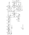
以下、本発明の実施の形態について、図を参照して詳細に説明する。本発明は、例えば図1に示すような構成のビデオカメラ100に適用される。
【0021】
このビデオカメラ100は、撮像レンズ系を介して撮像光が入射される撮像部12、当該ビデオカメラ100に接続される機器に応じた形式の撮像出力信号CMoutを上記撮像部12による撮像信号Spaから生成して出力する本線系ブロック11、上記本線系ブロック11により得られる画像信号Dqからモニタ用の撮像出力信号MToutを生成して 出力するモニタ系ブロック30、モニタ系ブロック30から供給される撮像出力信号MToutによる画像を液晶表示面を介して表示するビューファインダ300、上記本線系ブロック11、モニタ系ブロック30及びビューファインダ300の動作を制御する制御部50、上記制御部50にユーザ操作に応じた操作信号PSを供給するための操作部51等からなる。
【0022】
このビデオカメラ100において、撮像レンズ系10を通じて入射された光は、本線系ブロック11を構成する撮像部12に入射されて、撮像面上に被写体画像が結像される。撮像部12は、固体撮像素子例えばCCDイメージセンサを用いて構成されており、光電変換によって被写体画像に応じた三原色の撮像信号Spaを生成してCDS(Corelated Double Sampling)/AGC(Auto Gain Control)13に供給する。
【0023】
CDS/AGC13では、相関二重サンプリング処理を行い、撮像信号Spaからノイズ成分を除去する。さらにノイズ成分を除去した信号を所定の信号レベルに増幅して撮像信号Spbとして低域フィルタ(LPF)14に供給する。低減フィルタ14では、CDS/AGC13から供給された撮像信号Spbから、原信号スペクトル成分を取り出して撮像信号Spcとしてアンプ15に供給する。アンプ15では、供給された撮像信号Spcを増幅して撮像信号SpdとしてA/D変換器16に供給する。A/D変換器16では、供給された撮像信号Spdをディジタルの撮像信号Dpに変換してカメラ信号処理部20に供給する。
【0024】
カメラ信号処理部20では、良好な撮像画像を得ることができるように、供給された撮像信号Dpに対して信号処理を行う。例えば、シェーディング補正やマスキング補正、ニー補正、γ補正、輪郭補償等の信号処理を行い、撮像信号Dpから画像信号Dqを生成してセレクタ25とモニタ系ブロック30の画像表示部31に供給する。
【0025】
画像表示制御部31では、撮影画像の輝度を判別するための基準となる輝度基準画像の画像信号Drを生成すると共に、この画像信号Drとカメラ信号処理部20から供給された画像信号Dqを用いて、調整された画像信号を生成する。さらに生成された画像信号に対して信号処理、例えば輝度やコントラスト調整等の処理を行い、得られた画像信号Duをモニタ出力処理部35と本線系ブロック11のセレクタ25に供給する。なお、この画像表示制御部の詳細については、後に詳細に説明をする。
【0026】
セレクタ25では後述する制御部50からの制御信号に基づき、カメラ信号処理部20から供給された画像信号Dq、或いは画像表示制御部31から供給された画像信号Duのいずれかを選択してカメラ出力処理部28に供給する。
【0027】
カメラ出力処理部28では、セレクタ25から供給された画像信号Dq或いは画像信号Duを、ビデオカメラに接続される機器に応じた信号CMoutに変換して出力する。例えば、コンポーネント信号に対応した機器やコンポジット信号に対応した機器が接続される場合には、それぞれの機器に応じた信号CMoutに変換して出力する。またSMPTE259Mとして規格化されているシリアルディジタルインターフェース等を介して画像信号を伝送する場合には、セレクタ25から供給された画像信号を用いてインタフェース規格に応じた伝送データを生成して信号CMoutとして出力する。
【0028】
モニタ出力処理部35では、画像表示制御部31から供給された画像信号Duを、液晶表示部37に応じた信号MToutに変換して出力する。例えば液晶表示部37がアナログ信号を用いるものであるときには、画像信号Duをアナログ信号に変換して信号MToutとして出力する。
【0029】
例えば電子ビューファインダに代表される液晶表示部37は、多数の液晶表示素子等からなり、ユーザに対して情報を表示するディスプレイを構成する。この液晶表示部37は、モニタ出力処理部35から入力される信号MToutに基づき、液晶表示素子を光変調させてユーザに表示する画像を作り出す。
【0030】
スイッチング(SW)レギュレータ36では、画像表示制御部31或いは制御部50から供給された制御信号CTbcに基づいて、直流信号Cf生成し、これをロイヤー発振部38へ出力する。
【0031】
ロイヤー発振部38は、SWレギュレータ36から直流信号Cfが入力されると、自励式に発振して交流信号Chを発生させる。このロイヤー発振部38により発生させられた交流信号Chの振幅は、入力される直流信号の電圧値により支配される。交流信号Chは、バックライト39へ連続的に印加される。すなわち、この入力される直流信号の電圧値を制御することにより、バックライト39の照明輝度を変化させることができ、ひいては液晶表示部37に表示される画像のコントラストを調整することも可能となる。
【0032】
バックライト39は、液晶表示部37を構成する液晶表示素子の背面から照明光を照射することにより、上記液晶ディスプレイの視認性を確保するための蛍光管である。このバックライト39により照射される照明光の照明輝度は、印加された交流信号Chに基づく。
【0033】
制御部50には、操作部51が接続されており、かかる操作部51のユーザによる操作に応じて操作信号PSが制御部50に供給される。制御部50では、この操作信号PSに基づき各種の制御信号CTを生成して、ビデオカメラの本線系ブロック11やモニタ系ブロック30に供給することで、ユーザ操作に応じてビデオカメラを動作させる。また、制御部50には、画像表示制御部31から後述する判別信号Haが供給されており、この判別信号Haや操作信号PSに基づき制御信号CTbcを生成してモニタ系ブロック30に供給する。
【0034】
次に画像表示制御部31の詳細について説明をする。図2は、画像表示制御部31の構成を示している。
【0035】
カメラ信号処理部20から供給された画像信号Dqは、判別回路311と輝度/コントラスト調整回路314に供給される。判別回路311では、画像信号Dqの信号判別を行う。この信号判別では、画像信号Dqの信号フォーマットや画像信号Dqに基づく撮影画像の明るさ、色彩等の判別を行い、当該判別結果を示す判別信号Haを生成して制御部50に供給する。
【0036】
輝度/コントラスト調整回路314では、所望の輝度及びコントラストの画像信号を得ることができるように、制御部50から供給された制御信号CTbcに基づいて、カメラ信号処理部20から供給された画像信号Dqのゲインをコントロールすることにより輝度信号レベルを調整する。この輝度/コントラスト調整回路314で信号レベルの調整が行われた画像信号Dqは、画像信号Duとしてモニタ出力処理部35へ供給される。
【0037】
次に、このビデオカメラ100における画像表示制御部31、ビューファインダ300の動作について説明する。
【0038】
先ず画像表示制御部31において、カメラ信号処理部20からモニタ用の画像信号Dqが供給される。この供給された画像信号Dqは、それぞれ画像表示制御部31内の判別回路311並びに輝度/コントラスト調整回路314へ送信される。判別回路311において、受信した画像信号Dqに基づき上述した判別を実行した後、判別信号Haを制御部50へ供給する。
【0039】
制御部50は、供給された判別信号Haから、明るさ、色彩等の各画像情報の識別を行う。そしてこの制御部50は、識別結果に応じた設定値Rを含む制御信号CTbcを生成し、これを輝度/コントラスト調整回路314並びにSWレギュレータ36へ供給する。
【0040】
制御信号CTbcを受信した輝度/コントラスト調整回路314では、制御信号CTbcに含まれる設定値Rに応じて画像信号Dqの輝度信号レベルを上げるように調整し、或いは当該輝度信号レベルを下げるように調整して、画像信号Duを生成する。同様に、制御信号CTbcを受信したSWコントローラ36は、制御信号CTbcに含まれる設定値Rに応じてバックライト39の照明輝度を上げるように直流信号Cfの電圧値を上昇させ、或いは照明輝度を下げるように直流信号Cfの電圧値を減少させつつ、これをロイヤー発振部38へ供給する。
【0041】
なお、輝度/コントラスト調整回路314並びにSWレギュレータ36は、互いに連関して画像信号Du、直流信号Cfをそれぞれ生成することができる。すなわち、液晶表示部37に表示される画像のコントラストは、画像信号Duとして出力される輝度信号レベルと、バックライト39により照射される照明光の照明輝度との双方で連関して制御されていることになる。ちなみに、バックライト39により照射される照明光の照明輝度は随時SWレギュレータ36へ通知されるため、SWレギュレータ36は、かかる通知に基づいて直流信号Cfの電圧値をフィードバック制御することが可能となる。
【0042】
ちなみに、輝度/コントラスト調整回路314並びにSWレギュレータ36は、それぞれ制御信号CTbcに含まれる設定値Rにより、上述の如く互いに連関して制御される。例えば、輝度/コントラスト調整回路314により調整される輝度信号レベル、並びにSWレギュレータ36により制御される電圧値が、それぞれ設定値Rに応じて一義的に決まるものであれば、輝度/コントラスト調整回路314並びにSWレギュレータ36側において、設定値Rに対する輝度信号レベル並びに直流信号Cfの電圧値を予め決定しておくことにより、単一の設定値Rを供給することでこれを実現することができる。
【0043】
なお、バックライト39の照明輝度の最小値は、放電安定電流を維持する観点から制限される。換言すれば、バックライト39の照明輝度の最小値は、放電安定電流に応じて決まるため、SWレギュレータ36によるコントラスト可変範囲は一定範囲内に制限されることになる。しかしながら、画像信号Duに含まれる輝度信号レベル並びに直流信号Cfに含まれる電圧値を連関して制御することができる本発明では、かかるSWレギュレータ36のコントラスト可変範囲を超える場合であっても、それに応じて輝度信号レベルを変化させることにより、所望のコントラスト画像を液晶表示部37を介して表示させることができる。
【0044】
例えば黒レベルの画像信号Dqが入力された場合において、設定値Rを受信したSWレギュレータ36は、自身のコントラスト可変範囲内において照明輝度を下げるべく、直流信号Cfの電圧値を下げる。また輝度/コントラスト調整回路314は、SWレギュレータ36のコントラスト可変範囲を超える部分につき、輝度信号レベルを下げるように調整して、画像信号Duを生成する。これにより、黒レベルの画像信号が入力された場合においても、バックライト39の照明輝度と、表示画像の輝度信号レベルを互いに下げることができるため、従来技術の如く黒レベルが浮いて表示されることがなくなり、表示される画像全体の視認性を向上させることが可能となる。
【0045】
すなわち、本発明では、画像信号Duに含まれる輝度信号レベルと、直流信号Cfに含まれる電圧値とを連関して制御することにより、実際に液晶表示部37を介して表示される画像のコントラストを柔軟に調整することができる。ユーザにより視認される表示画像の輝度は、バックライト39の照明輝度と輝度信号レベルの積で表される。このため、黒レベル以外の画像信号が入力された場合であっても、輝度信号レベルと、照明輝度とを連関して制御することにより、液晶表示部37に表示される画像につき所望のコントラストを得ることができる。
【0046】
なお、本発明は上述した実施の形態に限定されるものではない。輝度/コントラスト調整回路314並びにSWレギュレータ36の連関制御は、制御信号CTbcに含まれる設定値Rを介して行う場合のみならず、例えば、両者間において互いに連絡を取り合うことにより実現してもよい。
【0047】
また本発明は、撮像部12を備えるビデオカメラ100に適用される場合のみならず、他の撮像装置で撮像された画像信号等が入力され、当該入力された画像信号のコントラストを調整して液晶表示面に表示する画像表示制御装置に適用してもよい。
【0048】
さらに本発明は、図3に示す構成のビューファインダ装置300Aに適用することもできる。
【0049】
この図3に示すビューファインダ装置300Aは、ビデオカメラ100A側のカメラ信号処理部20から供給される画像信号Dqにつき、輝度やコントラストの調整を施す輝度/コントラスト調整回路214と、この輝度/コントラスト調整回路214から供給される画像信号Duを液晶表示部37に応じた信号MToutに変換して出力するモニタ出力処理部235と、モニタ出力処理部35から入力される信号MToutに基づき、液晶表示素子を光変調させてユーザに表示する画像を作り出す液晶表示部237と、ビューファインダ装置300Aの各部を制御する制御部250と、ユーザによる操作に応じて操作信号PSを制御部に供給する操作部251と、制御部250から供給された制御信号CTbcに基づいて、直流信号Cfを生成するSWレギュレータ236と、入力された直流信号Cfに応じて自励式に発振して交流信号Chを発生させるロイヤー発振部238と、バックライト239とを備えている。このビューファインダ装置300Aの各部分の詳細は、ビデオカメラ100における同一の部材、要素の説明を引用して、説明を省略する。
【0050】
このビューファインダ装置300Aにおいて、制御部250は、ビデオカメラ100A側の制御部50と制御情報の授受を行うための例えばI2Cバスによる通信機能を備えている。そして、上記制御部250は、上記通信機能によりビデオカメラ100A側に対して、輝度信号レベルを制御する機能、及び/又はバックライト239の照明輝度を制御する機能の有無を問い合わせる。その結果、ビデオカメラ100A側に、かかる輝度信号レベルを制御する機能、及び/又はバックライト239の照明輝度を制御する機能が搭載されている場合に、制御部250は、制御部50に対してコントラストの調整するための信号(CTbc)の送信を促す。一方、ビデオカメラ100A側から何ら応答がない場合には、制御部250は、コントラストを調整する制御機能が何ら搭載されていないものと判断して、当該ビューファインダ装置300A自身によりコントラストを調整すべく制御信号CTbcを作り出す。
【0051】
このようなビューファインダ装置300Aによれば、ビデオカメラ100Aの性能如何にかかわらず、実際に液晶表示部を介して表示される画像のコントラストを柔軟に調整することができる。
【0052】
【発明の効果】
以上詳細に説明したように、本発明を適用した画像表示制御装置及び方法は、入力される画像信号に応じて、表示画像のコントラストを制御するための制御信号を生成し、生成した制御信号に基づき、入力される画像信号の輝度信号レベルの調整と連関して、液晶表示面に対する照明輝度を制御する。このため、本発明では、実際に液晶表示部を介して表示される画像のコントラストを柔軟に調整することができる。
【0053】
また、本発明を適用した撮像装置は、被写体を撮影して画像信号を生成し、生成した画像信号に応じて、表示画像のコントラストを制御するための制御信号を生成し、生成した制御信号に基づき、入力される画像信号の輝度信号レベルの調整と連関して、液晶表示面に対する照明輝度を制御する。このため、本発明では、撮像した被写体についても、実際に液晶表示部を介して表示される画像のコントラストを柔軟に調整することができる。
【0054】
さらに、本発明を適用したビューファインダ装置は、撮像装置から供給される画像信号に応じて、表示画像のコントラストを制御するための制御信号を生成し、生成した制御信号に基づき、入力される画像信号の輝度信号レベルの調整と連関して、液晶表示面に対する照明輝度を制御する。このため、本発明では、撮像装置の性能如何にかかわらず、実際に液晶表示部を介して表示される画像のコントラストを柔軟に調整することができる。
【図面の簡単な説明】
【図1】本発明を適用したビデオカメラの構成を示すブロック図である。
【図2】画像表示制御部の構成を示すブロック図である。
【図3】ビューファインダ装置の構成を示すブロック図である。
【図4】バックライトの駆動回路に供給するパルス信号の波形図である。
【図5】バックライトの発光輝度を制御する調光システムの例を示す図である。
【符号の説明】
10 撮像レンズ系、11 本線系ブロック、12 撮像部、13 CDS/AGC、14 低減フィルタ、15 アンプ、16 A/D変換器、20 カメラ信号処理部、25 セレクタ、28 カメラ出力処理部、30 モニタ系ブロック、31 画像表示制御部、35 モニタ出力処理部、36 SWレギュレータ、37 液晶表示部、38 ロイヤー発振部、39 バックライト、50 制御部、51 操作部、100,100A ビデオカメラ、300,300A ビューファインダ装置、311 判別回路、314 輝度/コントラスト調整回路[0001]
TECHNICAL FIELD OF THE INVENTION
The present invention relates to an image display control apparatus and method for controlling an image to be displayed via a liquid crystal display surface based on an input image signal and a captured image signal, and an imaging apparatus and method, and particularly to an image display suitable for adjusting contrast. The present invention relates to a control device and method, an imaging device and method.
[0002]
[Prior art]
For example, in an imaging device represented by a video camera, a captured image is displayed on a screen of an electronic viewfinder configured using a light modulation element such as a liquid crystal display element. A backlight, such as a flat fluorescent tube, is attached to the back of the electronic viewfinder, and by illuminating the backlight, the liquid crystal display element is illuminated from the back to improve visibility.
[0003]
In order to emit such a backlight, first, a horizontal synchronization signal is separated from an input image signal, a pulse signal is generated in accordance with the separated horizontal synchronization signal, and the pulse signal is generated by a backlight driving circuit. It is realized by supplying. Figure 4 shows a pulse signal which is continuously generated in the period of the horizontal frequency f H. By providing such a horizontal blanking period, it is possible to synchronize the light emission cycle of the backlight and the display state of the image, and it is possible to prevent flickering of the displayed image.
[0004]
Also, by changing the illumination luminance of the backlight, it is possible to adjust the contrast of the image on the electronic viewfinder. That is, by changing the pulse width PW of the pulse signal shown in FIG. 4 to be supplied to the backlight driving circuit, the average current value IE indicating the illumination luminance can be controlled. This can be realized by narrowing the pulse width P W of the pulse signal when suppressing the illumination luminance of the backlight, and widening the pulse width P W when improving the illumination luminance. As described above, the control of the average current value IE realized by changing the pulse width PW is conventionally realized by using a pulse width modulation circuit (PWM circuit) (for example, see Patent Document 1). . In this PWM circuit, the above-described pulse width PW is usually changed by controlling a period during which a pulse signal is turned on / off.
[0005]
By the way, when the signal level of the input image signal is very small, if the switching of the backlight is performed by turning on / off the pulse signal by using the PWM circuit as described above, it becomes noise, so that the displayed image becomes noise. Is significantly disturbed.
[0006]
For this reason, as shown in FIG. 5, for example, a
[0007]
The
[0008]
The dimming
[0009]
That is, in the
[0010]
[Patent Document 1]
Japanese Patent Application Laid-Open No. 2000-195695 [Patent Document 2]
JP-A-11-273891
[Problems to be solved by the invention]
However, in the above-described
[0012]
Therefore, the present invention has been devised in view of the above-described problems, and an object thereof is to provide an image display control apparatus and method capable of flexibly adjusting contrast with respect to an input image signal, It is an object to provide an imaging device and a method.
[0013]
[Means for Solving the Problems]
In order to solve the above-described problem, the present inventor generates a control signal for controlling the contrast of a display image in accordance with an input image signal, and based on the generated control signal, an input image. The present invention has invented an image display control apparatus and method for controlling the illumination luminance on the liquid crystal display surface in connection with the adjustment of the luminance signal level of the signal.
[0014]
That is, the image display control device to which the present invention is applied is supplied from a control signal generation unit that generates a control signal for controlling the contrast of a display image in accordance with an input image signal, and from the control signal generation unit. A level adjusting means for adjusting a luminance signal level of an input image signal based on the control signal; and a display image to be displayed via a liquid crystal display surface according to the luminance signal level adjusted by the level adjusting means. An image generating means, an illuminating means for illuminating the liquid crystal display surface, and an illumination control means for controlling an illumination luminance by the illuminating means based on a control signal supplied from the control signal generating means in association with the level adjusting means .
[0015]
Further, the image display control method to which the present invention is applied generates a control signal for controlling the contrast of a display image in accordance with an input image signal, and generates a control signal of the input image signal based on the generated control signal. Adjusts the luminance signal level, creates a display image to be displayed via the liquid crystal display surface according to the adjusted luminance signal level, and, based on the generated control signal, links the adjustment of the luminance signal level to the liquid crystal display. Controls the illumination brightness for the surface.
[0016]
In order to solve the above-described problems, the inventor generates an image signal by photographing a subject, generates a control signal for controlling contrast of a display image according to the generated image signal, and generates the control signal. Invented is an imaging device that controls the illumination luminance on the liquid crystal display surface in association with the adjustment of the luminance signal level of the input image signal based on the control signal.
[0017]
That is, an imaging apparatus to which the present invention is applied includes: an image signal generation unit configured to capture an object to generate an image signal; and a control signal generation unit configured to generate a control signal for controlling a contrast of a display image according to the image signal. Means, a level adjusting means for adjusting a luminance signal level of an input image signal based on a control signal supplied from the control signal generating means, and a liquid crystal display surface in accordance with the luminance signal level adjusted by the level adjusting means. An image generating means for generating a display image for display via the illuminating means, an illuminating means for illuminating the liquid crystal display surface, and a level adjusting means based on a control signal supplied from the control signal generating means. Lighting control means for controlling lighting brightness.
[0018]
The present inventor, in order to solve the above-described problem, generates a control signal for controlling the contrast of a display image in accordance with an image signal supplied from an imaging device, and based on the generated control signal, In connection with the adjustment of the luminance signal level of the image signal to be performed, an image display control device and method for controlling the illumination luminance on the liquid crystal display surface have been invented.
[0019]
That is, in a viewfinder device to which the present invention is applied, in a viewfinder device that displays an image based on a monitor image signal supplied from an imaging device through a liquid crystal display surface, a display image is displayed in accordance with the supplied image signal. Control signal generation means for generating a control signal for controlling the contrast of the image signal, level adjustment means for adjusting a luminance signal level of an input image signal based on a control signal supplied from the control signal generation means, and level adjustment Image generating means for generating a display image to be displayed via the liquid crystal display surface in accordance with the luminance signal level adjusted by the means, illuminating means for illuminating the liquid crystal display surface, and control supplied from the control signal generating means An illumination control unit that controls the illumination brightness of the illumination unit in association with the level adjustment unit based on the signal.
[0020]
BEST MODE FOR CARRYING OUT THE INVENTION
Hereinafter, embodiments of the present invention will be described in detail with reference to the drawings. The present invention is applied to, for example, a video camera 100 having a configuration as shown in FIG.
[0021]
The video camera 100 includes an
[0022]
In the video camera 100, light incident through an
[0023]
The CDS /
[0024]
The camera
[0025]
The image
[0026]
The
[0027]
The camera
[0028]
The monitor
[0029]
For example, a liquid
[0030]
The switching (SW)
[0031]
When the DC signal Cf is input from the
[0032]
The
[0033]
An
[0034]
Next, details of the image
[0035]
The image signal Dq supplied from the camera
[0036]
In the luminance /
[0037]
Next, operations of the image
[0038]
First, in the image
[0039]
The
[0040]
The luminance /
[0041]
The brightness /
[0042]
Incidentally, the brightness /
[0043]
Note that the minimum value of the illumination luminance of the
[0044]
For example, when the black-level image signal Dq is input, the
[0045]
That is, in the present invention, by controlling the luminance signal level included in the image signal Du and the voltage value included in the DC signal Cf in association with each other, the contrast of the image actually displayed via the liquid
[0046]
Note that the present invention is not limited to the above embodiment. The association control of the brightness /
[0047]
In addition, the present invention is applied not only to the video camera 100 including the
[0048]
Further, the present invention can be applied to the
[0049]
The
[0050]
In the
[0051]
According to such a
[0052]
【The invention's effect】
As described above in detail, the image display control device and method to which the present invention is applied generate a control signal for controlling the contrast of a display image in accordance with an input image signal, and generate the control signal based on the generated control signal. In accordance with the adjustment of the luminance signal level of the input image signal, the luminance of the liquid crystal display surface is controlled. Therefore, according to the present invention, the contrast of an image actually displayed via the liquid crystal display unit can be flexibly adjusted.
[0053]
Further, the imaging apparatus to which the present invention is applied captures a subject, generates an image signal, generates a control signal for controlling the contrast of a display image according to the generated image signal, and generates a control signal based on the generated control signal. In accordance with the adjustment of the luminance signal level of the input image signal, the luminance of the liquid crystal display surface is controlled. For this reason, in the present invention, the contrast of the image actually displayed via the liquid crystal display unit can be flexibly adjusted even for a captured subject.
[0054]
Further, the viewfinder device to which the present invention is applied generates a control signal for controlling the contrast of a display image in accordance with an image signal supplied from the imaging device, and based on the generated control signal, an input image. In connection with the adjustment of the luminance signal level of the signal, the illumination luminance on the liquid crystal display surface is controlled. Therefore, according to the present invention, the contrast of an image actually displayed via the liquid crystal display unit can be flexibly adjusted regardless of the performance of the imaging device.
[Brief description of the drawings]
FIG. 1 is a block diagram illustrating a configuration of a video camera to which the present invention has been applied.
FIG. 2 is a block diagram illustrating a configuration of an image display control unit.
FIG. 3 is a block diagram illustrating a configuration of a viewfinder device.
FIG. 4 is a waveform diagram of a pulse signal supplied to a backlight driving circuit.
FIG. 5 is a diagram illustrating an example of a dimming system that controls light emission luminance of a backlight.
[Explanation of symbols]
Claims (11)
上記制御信号生成手段より供給される制御信号に基づき、上記入力される画像信号の輝度信号レベルを調整するレベル調整手段と、
上記レベル調整手段により調整された輝度信号レベルに応じて、液晶表示面を介して表示するための表示画像を作り出す画像生成手段と、
上記液晶表示面を照明する照明手段と、
上記制御信号生成手段より供給される制御信号に基づき、上記レベル調整手段と連関して、上記照明手段による照明輝度を制御する照明制御手段とを備えること
を特徴とする画像表示制御装置。Control signal generating means for generating a control signal for controlling the contrast of the display image according to the input image signal;
Level adjusting means for adjusting a luminance signal level of the input image signal based on a control signal supplied from the control signal generating means;
Image generation means for creating a display image for display via a liquid crystal display surface according to the luminance signal level adjusted by the level adjustment means;
Lighting means for illuminating the liquid crystal display surface;
An image display control device, comprising: an illumination control unit that controls an illumination luminance of the illumination unit in association with the level adjustment unit based on a control signal supplied from the control signal generation unit.
を特徴とする請求項1記載の画像表示制御装置。2. The image display control device according to claim 1, wherein the level adjustment unit adjusts the luminance signal level to be lower when the control to the low illumination luminance is executed by the illumination control unit.
を特徴とする請求項1記載の画像表示制御装置。2. The image display control device according to claim 1, wherein the illumination control means determines a lower limit of the illumination luminance in accordance with a stable discharge current value on the liquid crystal display surface.
を特徴とする請求項3記載の画像表示制御装置。4. The image display control device according to claim 3, wherein said level adjustment means adjusts the luminance signal level to be lower when the illumination control means controls the illumination luminance to a lower limit.
上記生成した制御信号に基づき、上記入力される画像信号の輝度信号レベルを調整し、
上記調整した輝度信号レベルに応じて、液晶表示面を介して表示するための表示画像を作り出し、
上記生成した制御信号に基づき、上記輝度信号レベルの調整と連関して、上記液晶表示面に対する照明輝度を制御すること
を特徴とする画像表示制御方法。Generate a control signal for controlling the contrast of the display image according to the input image signal,
Based on the generated control signal, adjust the luminance signal level of the input image signal,
According to the adjusted luminance signal level, a display image to be displayed via the liquid crystal display surface is created,
An image display control method, comprising: controlling the illumination luminance on the liquid crystal display surface in association with the adjustment of the luminance signal level based on the generated control signal.
を特徴とする請求項4記載の画像表示制御方法。5. The image display control method according to claim 4, wherein said level adjusting means adjusts the luminance signal level to be lower when the control to the low illumination luminance is executed.
を特徴とする請求項4記載の画像表示制御方法。The image display control method according to claim 4, wherein the lower limit of the illumination luminance is determined according to a stable discharge current value on the liquid crystal display surface.
を特徴とする請求項7記載の画像表示制御方法。8. The image display control method according to claim 7, wherein when the illumination brightness is controlled to the lower limit, the brightness signal level is adjusted to be reduced.
上記画像信号に応じて、表示画像のコントラストを制御するための制御信号を生成する制御信号生成手段と、
上記制御信号生成手段より供給される制御信号に基づき、上記入力される画像信号の輝度信号レベルを調整するレベル調整手段と、
上記レベル調整手段により調整された輝度信号レベルに応じて、液晶表示面を介して表示するための表示画像を作り出す画像生成手段と、
上記液晶表示面を照明する照明手段と、
上記制御信号生成手段より供給される制御信号に基づき、上記レベル調整手段と連関して、上記照明手段による照明輝度を制御する照明制御手段とを備えること
を特徴とする撮像装置。Image signal generating means for generating an image signal by photographing a subject;
Control signal generating means for generating a control signal for controlling the contrast of a display image according to the image signal;
Level adjusting means for adjusting a luminance signal level of the input image signal based on a control signal supplied from the control signal generating means;
Image generation means for creating a display image for display via a liquid crystal display surface according to the luminance signal level adjusted by the level adjustment means;
Lighting means for illuminating the liquid crystal display surface;
An image pickup apparatus comprising: an illumination control unit configured to control an illumination luminance of the illumination unit in association with the level adjustment unit based on a control signal supplied from the control signal generation unit.
供給される画像信号に応じて、表示画像のコントラストを制御するための制御信号を生成する制御信号生成手段と、
上記制御信号生成手段より供給される制御信号に基づき、上記入力される画像信号の輝度信号レベルを調整するレベル調整手段と、
上記レベル調整手段により調整された輝度信号レベルに応じて、上記液晶表示面を介して表示するための表示画像を作り出す画像生成手段と、
上記液晶表示面を照明する照明手段と、
上記制御信号生成手段より供給される制御信号に基づき、上記レベル調整手段と連関して、上記照明手段による照明輝度を制御する照明制御手段とを備えること
を特徴とするビューファインダ装置。In a viewfinder device that displays an image based on a monitor image signal supplied from an imaging device through a liquid crystal display surface,
Control signal generating means for generating a control signal for controlling the contrast of a display image according to the supplied image signal;
Level adjusting means for adjusting a luminance signal level of the input image signal based on a control signal supplied from the control signal generating means;
Image generation means for creating a display image for display via the liquid crystal display surface, according to the luminance signal level adjusted by the level adjustment means,
Lighting means for illuminating the liquid crystal display surface;
A viewfinder device comprising: an illumination control unit that controls illumination luminance of the illumination unit in association with the level adjustment unit based on a control signal supplied from the control signal generation unit.
上記通信機能により、上記撮像装置側に表示画像のコントラストを制御する機能、及び/又は当該コントラストを制御する機能と連関して上記照明手段による照明輝度を制御する機能、の有無を問い合わせること
を特徴とする請求項10記載のビューファインダ装置。The control means has a communication function of exchanging control information with the imaging device,
The communication function inquires of the imaging device whether or not there is a function of controlling the contrast of the display image and / or a function of controlling the illumination luminance by the illumination unit in association with the function of controlling the contrast. The viewfinder device according to claim 10, wherein
Priority Applications (4)
| Application Number | Priority Date | Filing Date | Title |
|---|---|---|---|
| JP2002335582A JP2004170639A (en) | 2002-11-19 | 2002-11-19 | Image display controlling apparatus and method, imaging apparatus, and viewfinder device |
| US10/700,416 US7372474B2 (en) | 2002-11-19 | 2003-11-04 | Image display controlling apparatus and method, imaging apparatus and viewfinder device |
| DE60305416T DE60305416T2 (en) | 2002-11-19 | 2003-11-19 | Image reproduction control method and image viewer |
| EP03257322A EP1422934B1 (en) | 2002-11-19 | 2003-11-19 | Image display controlling method and viewfinder device |
Applications Claiming Priority (1)
| Application Number | Priority Date | Filing Date | Title |
|---|---|---|---|
| JP2002335582A JP2004170639A (en) | 2002-11-19 | 2002-11-19 | Image display controlling apparatus and method, imaging apparatus, and viewfinder device |
Publications (1)
| Publication Number | Publication Date |
|---|---|
| JP2004170639A true JP2004170639A (en) | 2004-06-17 |
Family
ID=32212070
Family Applications (1)
| Application Number | Title | Priority Date | Filing Date |
|---|---|---|---|
| JP2002335582A Abandoned JP2004170639A (en) | 2002-11-19 | 2002-11-19 | Image display controlling apparatus and method, imaging apparatus, and viewfinder device |
Country Status (4)
| Country | Link |
|---|---|
| US (1) | US7372474B2 (en) |
| EP (1) | EP1422934B1 (en) |
| JP (1) | JP2004170639A (en) |
| DE (1) | DE60305416T2 (en) |
Cited By (1)
| Publication number | Priority date | Publication date | Assignee | Title |
|---|---|---|---|---|
| CN113223465A (en) * | 2021-04-16 | 2021-08-06 | 深圳创维-Rgb电子有限公司 | Regional backlight demonstration method, device and storage medium |
Families Citing this family (4)
| Publication number | Priority date | Publication date | Assignee | Title |
|---|---|---|---|---|
| JP3968587B2 (en) * | 2004-03-30 | 2007-08-29 | 船井電機株式会社 | Liquid crystal television, backlight control device, and backlight control method |
| KR101305973B1 (en) * | 2006-11-15 | 2013-09-12 | 삼성디스플레이 주식회사 | Back light assembly and method of driving the same |
| WO2011154997A1 (en) * | 2010-06-09 | 2011-12-15 | 三菱電機株式会社 | Imaging system, imaging device and display device |
| CN111739452B (en) * | 2020-06-16 | 2022-06-07 | 深圳市华星光电半导体显示技术有限公司 | Method and device for debugging dark state voltage of liquid crystal display panel and storage medium |
Family Cites Families (11)
| Publication number | Priority date | Publication date | Assignee | Title |
|---|---|---|---|---|
| US5184117A (en) | 1989-06-28 | 1993-02-02 | Zenith Data Systems Corporation | Fluorescent backlight flicker control in an LCD display |
| JPH05292364A (en) | 1992-04-14 | 1993-11-05 | Sony Corp | Display device |
| US5699115A (en) | 1994-05-10 | 1997-12-16 | Sony Corporation | Electronic viewfinder having means for turning off a display device |
| JPH08191408A (en) | 1995-01-10 | 1996-07-23 | Hitachi Ltd | Camcorder with liquid crystal display device |
| JP2771499B2 (en) * | 1995-12-19 | 1998-07-02 | 静岡日本電気株式会社 | Individually selected call receiver with display |
| US6411306B1 (en) * | 1997-11-14 | 2002-06-25 | Eastman Kodak Company | Automatic luminance and contrast adustment for display device |
| JP4099552B2 (en) | 1998-08-03 | 2008-06-11 | ソニー株式会社 | IMAGING DISPLAY DEVICE AND IMAGING DISPLAY DEVICE CONTROL METHOD |
| JP2000195695A (en) | 1998-12-28 | 2000-07-14 | Sony Corp | Back light driving method, back light driving circuit and electronic apparatus |
| TWI285872B (en) | 1999-05-10 | 2007-08-21 | Matsushita Electric Ind Co Ltd | Image display device and method for displaying image |
| JP2001305637A (en) | 2000-04-26 | 2001-11-02 | Kyocera Corp | Camera with electronic viewfinder |
| US7119786B2 (en) * | 2001-06-28 | 2006-10-10 | Intel Corporation | Method and apparatus for enabling power management of a flat panel display |
-
2002
- 2002-11-19 JP JP2002335582A patent/JP2004170639A/en not_active Abandoned
-
2003
- 2003-11-04 US US10/700,416 patent/US7372474B2/en not_active Expired - Fee Related
- 2003-11-19 DE DE60305416T patent/DE60305416T2/en not_active Expired - Fee Related
- 2003-11-19 EP EP03257322A patent/EP1422934B1/en not_active Expired - Fee Related
Cited By (1)
| Publication number | Priority date | Publication date | Assignee | Title |
|---|---|---|---|---|
| CN113223465A (en) * | 2021-04-16 | 2021-08-06 | 深圳创维-Rgb电子有限公司 | Regional backlight demonstration method, device and storage medium |
Also Published As
| Publication number | Publication date |
|---|---|
| US7372474B2 (en) | 2008-05-13 |
| DE60305416T2 (en) | 2007-05-03 |
| EP1422934A1 (en) | 2004-05-26 |
| EP1422934B1 (en) | 2006-05-24 |
| US20040095363A1 (en) | 2004-05-20 |
| DE60305416D1 (en) | 2006-06-29 |
Similar Documents
| Publication | Publication Date | Title |
|---|---|---|
| JP4927311B2 (en) | VIDEO DISPLAY DEVICE, DISPLAY UNIT DRIVE CIRCUIT USED FOR THE SAME | |
| JP4117074B2 (en) | Liquid crystal display | |
| US6466196B1 (en) | Method of driving backlight, circuit for driving backlight, and electronic apparatus | |
| JP3968587B2 (en) | Liquid crystal television, backlight control device, and backlight control method | |
| JP3375557B2 (en) | Video signal processing device | |
| JP2003283930A (en) | Exposure controlling method, exposure controlling circuit, imaging device, program, storage medium | |
| JP2003177727A (en) | Image display device and light quantity adjusting method | |
| JP2006317757A (en) | Liquid crystal display device, portable terminal device provided with the same, and liquid crystal display method | |
| JP2008286832A (en) | Liquid crystal display apparatus and liquid crystal television | |
| US6404145B1 (en) | Apparatus for and method of controlling backlight for liquid crystal display | |
| US9961270B2 (en) | Imaging system and processing device | |
| JP2004170639A (en) | Image display controlling apparatus and method, imaging apparatus, and viewfinder device | |
| JP2009192853A (en) | Automatic dimming system | |
| JP4221593B2 (en) | Liquid crystal television, backlight control device, and backlight control method | |
| JP4300810B2 (en) | Discharge lamp lighting device | |
| US6456317B1 (en) | Endoscopic apparatus | |
| JP4083952B2 (en) | Backlight control device and method for liquid crystal display device | |
| JP4440562B2 (en) | Video signal processing device | |
| JP2001203910A (en) | Video signal processor | |
| US8638360B2 (en) | Process of real time adjustment of the sensitivity of a video image sensor of a videoendoscopic probe | |
| JP4033565B2 (en) | Endoscope device | |
| JP2000032352A (en) | Video camera device | |
| KR100467592B1 (en) | Apparatus and method for display | |
| JP2003348497A (en) | Display apparatus and imaging apparatus | |
| KR0133695Y1 (en) | Endoscope system |
Legal Events
| Date | Code | Title | Description |
|---|---|---|---|
| A621 | Written request for application examination |
Free format text: JAPANESE INTERMEDIATE CODE: A621 Effective date: 20050715 |
|
| A977 | Report on retrieval |
Free format text: JAPANESE INTERMEDIATE CODE: A971007 Effective date: 20081210 |
|
| A131 | Notification of reasons for refusal |
Free format text: JAPANESE INTERMEDIATE CODE: A131 Effective date: 20081224 |
|
| A521 | Request for written amendment filed |
Free format text: JAPANESE INTERMEDIATE CODE: A523 Effective date: 20090223 |
|
| A762 | Written abandonment of application |
Free format text: JAPANESE INTERMEDIATE CODE: A762 Effective date: 20090824 |